EP3217048A1 - Mechanical sealing device - Google Patents
Mechanical sealing device Download PDFInfo
- Publication number
- EP3217048A1 EP3217048A1 EP15857687.6A EP15857687A EP3217048A1 EP 3217048 A1 EP3217048 A1 EP 3217048A1 EP 15857687 A EP15857687 A EP 15857687A EP 3217048 A1 EP3217048 A1 EP 3217048A1
- Authority
- EP
- European Patent Office
- Prior art keywords
- diameter
- seal cover
- side seal
- seal
- cover
- Prior art date
- Legal status (The legal status is an assumption and is not a legal conclusion. Google has not performed a legal analysis and makes no representation as to the accuracy of the status listed.)
- Granted
Links
Images

Classifications
-
- F—MECHANICAL ENGINEERING; LIGHTING; HEATING; WEAPONS; BLASTING
- F16—ENGINEERING ELEMENTS AND UNITS; GENERAL MEASURES FOR PRODUCING AND MAINTAINING EFFECTIVE FUNCTIONING OF MACHINES OR INSTALLATIONS; THERMAL INSULATION IN GENERAL
- F16J—PISTONS; CYLINDERS; SEALINGS
- F16J15/00—Sealings
- F16J15/16—Sealings between relatively-moving surfaces
- F16J15/34—Sealings between relatively-moving surfaces with slip-ring pressed against a more or less radial face on one member
- F16J15/3464—Mounting of the seal
Definitions
- the present invention relates to a mechanical seal device used as an axial seal for rotating equipment in chemical, food, general industry and other applications.
- a traditional bellows-type mechanical seal device has a seal ring held on a retainer which is fixed to a bellows, and an opposing mating ring that slidably contacts the seal ring, wherein the seal ring is supported on a seal cover via the retainer, bellows, and an adapter, and the mating ring is supported on a rotating shaft and rotates with the rotating shaft (refer to Patent Literature 1, for example).
- Patent Literature 1 International Patent Laid-open No. 2010/116844 (Paragraph 0016, FIG. 1 )
- the retainer, bellows, adapter, and seal cover constituting the fixed-side seal assembly are fixed to each other by means of welding, etc. And, the seal cover is fixed to an equipment main body via bolts and nuts.
- the bolts and nuts fixing the seal cover to the equipment main body must be unfastened and the fixed-side seal assembly must be removed in the axial direction together with the seal cover before the maintenance can be performed.
- the seal cover removed at the time of maintenance is structured in such a way that it covers the seal ring or other seal element in the radial direction and axial direction of the rotating shaft and is therefore considerably large in the radial direction and axial direction and heavy, which gives rise to the problem of difficulty handling the seal ring, etc., during maintenance as it is connected to the seal cover via the bellows, etc. This problem is particularly noticeable with mechanical seal devices used for large equipment.
- the present invention was conceived from recognizing this problem, and its object is to provide a mechanical seal device with improved seal cover structure that achieves excellent ease of handling the seal ring or other seal element during maintenance.
- the mechanical seal device proposed by the present invention has:
- the seal ring is connected to the inner-diameter-side seal cover in a securely following manner, and the inner-diameter-side seal cover is detachably connected to the outer-diameter-side seal cover, so by removing the seal ring from the outer-diameter-side seal cover together with the inner-diameter-side seal cover, maintenance of the seal ring, etc., can be performed on the connection piece which has a small outer shape, is lightweight, and offers excellent ease of handling.
- the seal cover is a three-part split structure comprising at least the inner-diameter-side seal cover, outer-diameter-side seal cover, and an axial-direction seal cover, the inner-diameter-side seal cover, outer-diameter-side seal cover, and axial-direction seal cover are each detachably connected, and a feed hole is provided in the axial-direction seal cover through which fluid is fed from the outside into the space where the seal ring is placed.
- a flange is formed on the inner-diameter-side seal cover, and the inner-diameter-side seal cover is fixed to the outer-diameter-side seal cover by a fixing means in a state where this flange is abutting the inner side of the outer-diameter-side seal cover in the axial direction.
- the pressure acting upon the inner-diameter-side seal cover from the inner side of the mechanical seal device is primarily received by the outer-diameter-side seal cover via the flange of the inner-diameter-side seal cover, which effectively prevents the inner-diameter-side seal cover from separating from the outer-diameter-side seal cover.
- the fixing means is a coupling bolt with head which is installed on the inner-diameter-side seal cover, from the outer side in the axial direction, at a position on the inner diameter side of the outer-diameter-side seal cover, and a part of the head of the coupling bolt abuts the outer-side seal cover.
- the fixing means provides fixing in which the flange of the inner-diameter-side seal cover is sandwiched between the outer-diameter-side seal cover and axial-direction seal cover in the axial direction.
- the inner-diameter-side seal cover is sandwiched between the outer-diameter-side seal cover and axial-direction seal cover in the axial direction and this improves the fixed strength of the inner-diameter-side seal cover.
- the mechanical seal device pertaining to Example 1 is explained by referring to FIGS. 1 to 3 .
- the top and bottom of FIG. 1 represent the top and bottom of the mechanical seal device, while the inner side and atmosphere side of the mechanical seal device represent the inner side and outer side, respectively.
- a mechanical seal device 4 is of the so-called tandem type, where a primary-side mechanical seal 20 and secondary-side mechanical seal 30 are used to axially seal between a rotating shaft 1 extending in the vertical direction and a seal cover 5 enclosing the rotating shaft 1.
- a pump impeller (not illustrated) housed in an equipment main body 2 is fixed to the bottom of the rotating shaft 1.
- the seal cover 5 is fixed to the equipment main body 2 by a bolt 9 and nut 10 and encloses the rotating shaft 1 in the axial direction and radial direction.
- the seal cover 5 is formed by an axial-direction seal cover 6 which is fixed to the equipment main body 2 with the bolt 9 and nut 10 via a gasket 6a, and an outer-diameter-side seal cover 7 and inner-diameter-side seal cover 8 which are connected to the end of the axial-direction seal cover 6 and seal in the radial direction.
- These seal covers 6, 7, 8 are formed by stainless steel, aluminum alloy, or other metal.
- the outer-diameter-side seal cover 7 has a circular cutout at the bottom on the inner diameter side, and also has a circular projection 7a formed at the top which projects toward the inner diameter side.
- the inner-diameter-side seal cover 8 has a circular cutout at the top on the outer diameter side, and also has a circular projection 8a (flange) formed at the bottom which projects toward the outer diameter side.
- the circular sleeve 13a is restrained by a split ring 13c from moving outward in the axial direction.
- a sleeve collar 14 presses a gasket 14a against the end face of the sleeve 12 to seal along the rotating shaft 1.
- the primary-side mechanical seal 20 comprises: a mating ring 21 which is closely fitted and fixed via a retainer to the bottom outer periphery of the sleeve 12 and rotates with the rotating shaft 1; a fixed-side seal ring 23 that slidably contacts the mating ring 21; a retainer 24 that holds the seal ring 23 in place; a bellows 25 which is welded and fixed to the retainer 24 and adds bias force in the axial direction; and an adapter 26 whose one end is welded and fixed to the bellows 25 and other end is fixed by a bolt 27 to the bottom surface of the circular projection projecting toward the inner diameter side of the axial-direction seal cover 6. It should be noted that the seal ring 23, retainer 24, bellows 25, and adapter 26 constitute a fixed-side seal assembly 22.
- the secondary-side mechanical seal 30 comprises: a mating ring 31 which is closely fitted and fixed to the center outer periphery of the sleeve 12 and rotates with the rotating shaft 10; a fixed-side seal ring 33 that slidably contacts the mating ring 31; a retainer 34 that holds the seal ring 33 in place; a bellows 35 which is welded and fixed to the retainer 34 and adds bias force in the axial direction; and an adapter 36 whose one end is welded and fixed to the bellows 35 and other end is welded and fixed, along its outer periphery, to the inner periphery of the inner-diameter-side seal cover 8.
- seal ring 33, retainer 34, bellows 35, and adapter 36 constitute a fixed-side seal assembly 32.
- the fixed-side seal assembly 32 is connected to the inner-diameter-side seal cover 8 in a securely following manner.
- the primary-side mechanical seal 20 seals a liquid or gas 3 in the pump chamber (not illustrated) present below it, and this liquid or gas 3 is partly transferred to an outer periphery space C of the primary-side mechanical seal 20 and circulated back therefrom toward the pump chamber side through a flushing drain hole 6c (feed hole) in the axial-direction seal cover 6 for flushing. This way, the sealed sliding surface of the primary-side mechanical seal 20 is lubricated/cooled.
- external liquid 37 is sealed in an interim chamber B between the primary-side mechanical seal 20 and secondary-side mechanical seal 30, filling the chamber to its top.
- an inlet hole (not illustrated) which connects to the interim chamber B housing the primary-side mechanical seal 20 and through which the external liquid 37 flows in from the outside, while provided upward of it is an outlet hole 6d (feed hole) which connects to the interim chamber B housing the secondary-side mechanical seal 30 and through which the external liquid 37 flows out to the outside, and the external liquid 37 keeps the interim chamber B at a desired pressure.
- the external liquid 37 is circulated by an impeller formed on the sleeve 12.
- Step 1 As a preparation, the liquid or gas 3 in the pump chamber is drained and the external liquid 37 in the interim chamber B is drained from a drain port (not illustrated). With a set plate (not illustrated) engaging with a concave part 13b of the circular sleeve 13a, the set plate is installed to the outer-diameter-side seal cover 7 by a set plate bolt (not illustrated), after which the setscrew 13 and nut 10 are removed and the mechanical seal device 4 is removed from the equipment main body 2.
- Step 2 The set plate bolt is loosened and the set plate is removed, and the split ring 13c and sleeve collar 14 are removed, as well.
- Step 3 The nut 10 and bolt (not illustrated) are removed, and while holding the outer-diameter-side seal cover 7, the outer-diameter-side seal cover 7, inner-diameter-side seal cover 8 and fixed-side seal assembly 32 are pulled out upward in the axial direction (toward atmosphere A).
- FIG. 2 shows the state after these have been pulled out.
- Step 4 The coupling bolt 11 is loosened and the outer-diameter-side seal cover 7 is removed from the inner-diameter-side seal cover 8.
- FIG. 3 shows the state after the seal cover has been removed.
- Step 5 Maintenance of the fixed-side seal assembly 32 is performed, such as repairing the seal ring 33.
- Step 6 Steps 1 to 5 above are performed in the reverse order to restore the original state.
- the outer-diameter-side seal cover 7 can be removed from the inner-diameter-side seal cover 8 to which the seal ring 31 is connected. Because of this, the fixed-side seal assembly 32 having the seal ring 33 connected to the inner-diameter-side seal cover 8 via the bellows 35 becomes smaller in outer shape and lighter in weight, resulting in excellent ease of handling the seal ring 33, etc., during maintenance. Furthermore, if a need arises to replace the fixed-side seal assembly 32, the outer-diameter-side seal cover 7 can be removed from the assembly shown in FIG. 2 and this eliminates the need to replace the outer-diameter-side seal cover 7, and because all that is needed is to replace the fixed-side seal assembly 32 and inner-diameter-side seal cover 32, excellent economy is achieved.
- outer-diameter-side seal cover 7 and inner-diameter-side seal cover 8 have no feed hole for external liquid or other fluid, which eliminates the need to elongate the outer-diameter-side seal cover 7 and inner-diameter-side seal cover 8 in the axial direction so that they can be made small/lightweight as a result, and this leads to excellent ease of handling the outer-diameter-side seal cover and inner-diameter-side seal cover when they are removed from the axial-direction seal cover together.
- the coupling bolt 11 can be fastened to the inner-diameter-side seal cover 8 without causing the projection 7a of the outer-diameter-side seal cover 7 to penetrate through, which allows the inner-diameter-side seal cover 8 to be constituted shorter in the axial direction and lighter.
- the fastening force by the coupling bolt 11 can be low. Furthermore, since the inner-diameter-side seal cover 8 is sandwiched between the outer-diameter-side seal cover 7 and axial-direction seal cover 6 in the axial direction besides being fixed by a connecting member which is the coupling bolt 11, the connecting member 11 to be used can be one of low fastening force.
- the inner-diameter-side seal cover 8 and outer-diameter-side seal cover 7 can be made shorter in the axial direction (made thinner), the axial-direction seal cover 6 can be extended higher (formed longer in the axial direction), which in rotate increases the degree of freedom of selecting the location of the outlet hole 6d in the axial-direction seal cover 6.
- the outlet hole 6d can be placed even higher to keep gas from collecting above the interim chamber B.
- Example 2 differs from Example 1 in the shapes of the outer-diameter-side seal cover and inner-diameter-side seal cover and their connection structure, and these items different from Example 1 are explained below.
- an outer-diameter-side seal cover 7' has a circular cutout at the top on the inner diameter side, and also has a circular projection 7a' formed at the bottom which projects toward the inner diameter side.
- An inner-diameter-side seal cover 8' has a circular cutout at the bottom on the outer diameter side, and also has a circular projection 8a' (flange) formed at the top which projects toward the inner diameter side.
- the coupling bolt 11' can be fastened to the outer-diameter-side seal cover 7' without causing the projection 8a' of the inner-diameter-side seal cover 8' to penetrate through, which allows the outer-diameter-side seal cover 7' to be constituted shorter in the axial direction and lighter, while also achieving excellent ease of maintenance because the inner-diameter-side seal cover 8' can be removed without removing the outer-diameter-side seal cover 7'.
- the mechanical seal device pertaining to Example 3 is explained by referring to FIGS. 5 to 7 .
- the top and bottom of FIG. 5 represent the top and bottom of the mechanical seal device, while the inner side and atmosphere side of the mechanical seal device represent the inner side and outer side, respectively.
- a mechanical seal device 104 is of the so-called back-to-back double type, where a primary-side mechanical seal 120 and secondary-side mechanical seal 130 are used to axially seal between a rotating shaft 101 extending in the vertical direction and a seal cover 105 enclosing the rotating shaft 101.
- a pump impeller housed in an equipment main body 102 is fixed to the bottom of the rotating shaft 101.
- the seal cover 105 is fixed to the equipment main body 102 by a bolt 109 and nut 110 and encloses the rotating shaft 101 in the axial direction and radial direction.
- the seal cover 105 is formed by an axial-direction seal cover 106 which is fixed to the equipment main body 102 with the bolt 109 and nut 110 via a gasket 106a, and an outer-diameter-side seal cover 107 and inner-diameter-side seal cover 108 which are connected to the end of the axial-direction seal cover 106 and seal in the radial direction.
- These seal covers 106, 107, 108 are formed by stainless steel, aluminum alloy, or other metal.
- the outer-diameter-side seal cover 107 has a circular cutout at the top on the inner diameter side (end face side on the atmosphere A side), and also has a circular projection 107a formed below the cutout and projecting toward the inner diameter side.
- the inner-diameter-side seal cover 108 has a circular cutout at the bottom on the outer diameter side, and also has a circular projection 108a (flange) formed above the cutout and projecting toward the outer diameter side, and a counter bore 108d to accommodate a head 111b of a coupling bolt 111 (fixing means) is formed in the circular projection 108a.
- the projection 107a of the outer-diameter-side seal cover 107 is aligned in position with the cutout in the inner-diameter-side seal cover and then the coupling bolt 111 is guided from above through a through hole 108b provided in the projection 108a and through hole in the gasket 108e to cause a male thread 111a of the coupling bolt 111 to be screwed to a female thread 107c of the projection 107a, so that the inner-diameter-side seal cover 108 is fixed to the outer-diameter-side seal cover 107 as a result.
- the outer-diameter-side seal cover 107 is fixed to the axial-direction seal cover 106 by fastening a bolt (not illustrated).
- the outer-diameter-side seal cover 107 and axial-direction seal cover 106 are sealed by a gasket 107d.
- the circular sleeve 113a is restrained by a split ring 113c from moving outward in the axial direction.
- a sleeve collar 114 presses a gasket 114a against the end face of the sleeve 112 to seal along the rotating shaft 101.
- the primary-side mechanical seal 120 comprises: a mating ring 121 which is closely fitted and fixed to the bottom of a circular projection 112a of the sleeve 112 and rotates with the rotating shaft 101; a fixed-side seal ring 123 that slidably contacts the mating ring 121; a retainer 124 that holds the seal ring 123 in place; a bellows 125 which is welded and fixed to the retainer 124 and adds bias force in the axial direction; and an adapter 126 whose one end is welded and fixed to the bellows 125 and other end is fixed by a bolt 127 to the inner periphery of the axial-direction seal cover 106. It should be noted that the seal ring 123, retainer 124, bellows 125, and adapter 126 constitute a fixed-side seal assembly 122.
- the secondary-side mechanical seal 130 comprises: a mating ring 131 which is closely fitted and fixed to the top of the circular projection 112a of the sleeve 112 and rotates with the rotating shaft 101; a fixed-side seal ring 133 that slidably contacts the mating ring 131; a retainer 134 that holds the seal ring 133 in place; a bellows 135 which is welded and fixed to the retainer 134 and adds bias force in the axial direction; and an adapter 136 whose one end is welded and fixed to the bellows 135 and other end is welded and fixed, along its outer periphery, to the inner periphery of the inner-diameter-side seal cover 108.
- seal ring 133, retainer 134, bellows 135, and adapter 136 constitute a fixed-side seal assembly 132.
- the fixed-side seal assembly 132 is connected to the inner-diameter-side seal cover 108 in a securely following manner.
- external liquid 137 is sealed in an interim chamber B between the primary-side mechanical seal 120 and secondary-side mechanical seal 130, filling the chamber to its top.
- an inlet hole 106b feed hole
- an outlet hole 107b which connects to the interim chamber B housing the secondary-side mechanical seal 130 and through which the external liquid 137 flows out to the outside, and the external liquid 137 keeps the interim chamber B at a desired pressure.
- the external liquid 137 is circulated by an impeller 112b provided on the sleeve 112.
- Step 1 As a preparation, a liquid or gas 103 in the pump chamber is drained and the external liquid 137 in the interim chamber B is drained from a drain port (not illustrated). With a set plate (not illustrated) engaging with a concave part 113b of the circular sleeve 113a, the set plate is installed to the outer-diameter-side seal cover 107 by a set plate bolt (not illustrated), after which the setscrew 113 and nut 110 are removed and the mechanical seal device 104 is removed from the equipment main body 102.
- Step 2 The set plate bolt is loosened and the set plate is removed, and the split ring 113c and sleeve collar 114 are removed, as well.
- Step 3 The coupling bolt 111 is loosened and the outer-diameter-side seal cover 107 is removed from the inner-diameter-side seal cover 108.
- Step 7 shows the state after the seal cover has been removed.
- Step 4 Maintenance of the fixed-side seal assembly 132 is performed, such as repairing the seal ring 133.
- Step 5 Steps 1 to 4 above are performed in the reverse order to restore the original state.
- the outer-diameter-side seal cover 107 can be removed from the inner-diameter-side seal cover 108 to which the seal ring 131 is connected.
- the fixed-side seal assembly 132 having the seal ring 133 connected to the inner-diameter-side seal cover 108 via the bellows 135 becomes smaller in outer shape and lighter in weight, resulting in excellent ease of handling the seal ring 133, etc., during maintenance.
- the outer-diameter-side seal cover 107 can be removed from the assembly shown in FIG. 6 and this eliminates the need to replace the outer-diameter-side seal cover 107, and because all that is needed is to replace the fixed-side seal assembly 132 and inner-diameter-side seal cover 108, excellent economy is achieved.
- the inner-diameter-side seal cover 108 has no feed hole for external liquid or other fluid and the outlet hole 107b is provided in the outer-diameter-side seal cover 107 extending to the top, which increases the degree of freedom of selecting the location of the outlet hole 107b.
- the outlet hole 107b can be placed even higher to keep gas from collecting above the interim chamber B.
- the inner-diameter-side seal cover 108 and fixed-side seal assembly 132 can be removed simply by loosening the coupling bolt 111, without loosening the nut 110 in step 3 above, or specifically with the outer-diameter-side seal cover 107 still fixed to the axial-direction seal cover 106.
- FIG. 7 shows the state after these have been removed.
- any fixed-side seal assembly may be used so long as it has at least a seal ring.
- any fixed-side seal assembly may be used so long as a seal ring is connected to its inner-diameter-side seal cover.
- the outer-diameter-side seal cover 7, 7' or 107 is made of stainless steel known for its excellent rigidity and corrosion resistance
- the inner-diameter-side seal cover 8, 8' or 108 can have relatively lower rigidity and therefore it suffices that this seal cover is constituted by a material offering excellent corrosion resistance, such as a resin molding or a metal other than stainless steel with corrosion-resistant coating applied to it.
Landscapes
- Engineering & Computer Science (AREA)
- General Engineering & Computer Science (AREA)
- Mechanical Engineering (AREA)
- Mechanical Sealing (AREA)
Abstract
Description
- The present invention relates to a mechanical seal device used as an axial seal for rotating equipment in chemical, food, general industry and other applications.
- A traditional bellows-type mechanical seal device has a seal ring held on a retainer which is fixed to a bellows, and an opposing mating ring that slidably contacts the seal ring, wherein the seal ring is supported on a seal cover via the retainer, bellows, and an adapter, and the mating ring is supported on a rotating shaft and rotates with the rotating shaft (refer to
Patent Literature 1, for example). - Patent Literature 1: International Patent Laid-open No.
2010/116844 (Paragraph 0016,FIG. 1 ) - With the mechanical seal device described in
Patent Literature 1, the retainer, bellows, adapter, and seal cover constituting the fixed-side seal assembly are fixed to each other by means of welding, etc. And, the seal cover is fixed to an equipment main body via bolts and nuts. When correcting the sliding contact surface of the seal ring or performing other maintenance, therefore, the bolts and nuts fixing the seal cover to the equipment main body must be unfastened and the fixed-side seal assembly must be removed in the axial direction together with the seal cover before the maintenance can be performed. - However, the seal cover removed at the time of maintenance is structured in such a way that it covers the seal ring or other seal element in the radial direction and axial direction of the rotating shaft and is therefore considerably large in the radial direction and axial direction and heavy, which gives rise to the problem of difficulty handling the seal ring, etc., during maintenance as it is connected to the seal cover via the bellows, etc. This problem is particularly noticeable with mechanical seal devices used for large equipment.
- The present invention was conceived from recognizing this problem, and its object is to provide a mechanical seal device with improved seal cover structure that achieves excellent ease of handling the seal ring or other seal element during maintenance.
- To achieve the aforementioned object, the mechanical seal device proposed by the present invention has:
- a mating ring that rotates with a rotating shaft, as well as an opposing seal ring that slidably contacts the mating ring, so as to seal between the rotating shaft and a seal cover fixed to an equipment main body;
- wherein such mechanical seal device is characterized in that the seal cover is a split structure comprising at least an inner-diameter-side seal cover and an outer-diameter-side seal cover, the inner-diameter-side seal cover is detachably connected to the outer-diameter-side seal cover, and the seal ring is connected to the inner-diameter-side seal cover in a securely following manner.
- According to this characteristic, the seal ring is connected to the inner-diameter-side seal cover in a securely following manner, and the inner-diameter-side seal cover is detachably connected to the outer-diameter-side seal cover, so by removing the seal ring from the outer-diameter-side seal cover together with the inner-diameter-side seal cover, maintenance of the seal ring, etc., can be performed on the connection piece which has a small outer shape, is lightweight, and offers excellent ease of handling.
- Another characteristic is that the seal cover is a three-part split structure comprising at least the inner-diameter-side seal cover, outer-diameter-side seal cover, and an axial-direction seal cover, the inner-diameter-side seal cover, outer-diameter-side seal cover, and axial-direction seal cover are each detachably connected, and a feed hole is provided in the axial-direction seal cover through which fluid is fed from the outside into the space where the seal ring is placed.
- According to this characteristic, there is no need to form a feed hole in the inner-diameter-side seal cover or in the outer-diameter-side seal cover, which makes it possible to form the outer-diameter-side seal cover and inner-diameter-side seal cover small and lightweight, resulting in greater ease of handling the seal covers during maintenance.
- Another characteristic is that a flange is formed on the inner-diameter-side seal cover, and the inner-diameter-side seal cover is fixed to the outer-diameter-side seal cover by a fixing means in a state where this flange is abutting the inner side of the outer-diameter-side seal cover in the axial direction.
- According to this characteristic, the pressure acting upon the inner-diameter-side seal cover from the inner side of the mechanical seal device is primarily received by the outer-diameter-side seal cover via the flange of the inner-diameter-side seal cover, which effectively prevents the inner-diameter-side seal cover from separating from the outer-diameter-side seal cover.
- Another characteristic is that the fixing means is a coupling bolt with head which is installed on the inner-diameter-side seal cover, from the outer side in the axial direction, at a position on the inner diameter side of the outer-diameter-side seal cover, and a part of the head of the coupling bolt abuts the outer-side seal cover.
- According to this characteristic, there is no need for a hole, etc., in the outer-diameter-side seal cover through which to connect the coupling bolt, which simplifies the structure of the fixing means.
- Another characteristic is that the fixing means provides fixing in which the flange of the inner-diameter-side seal cover is sandwiched between the outer-diameter-side seal cover and axial-direction seal cover in the axial direction.
- According to this characteristic, the inner-diameter-side seal cover is sandwiched between the outer-diameter-side seal cover and axial-direction seal cover in the axial direction and this improves the fixed strength of the inner-diameter-side seal cover.
-
- [
FIG. 1 ] Section view of the mechanical seal device in Example 1. - [
FIG. 2 ] Section view of the mechanical seal device inFIG. 1 , showing a state where the outer-diameter-side and inner-diameter-side seal covers are removed. - [
FIG. 3 ] Section view of the seal cover inFIG. 2 , showing a state where the inner-diameter-side seal cover is removed. - [
FIG. 4 ] Section view of the mechanical seal device in Example 2. - [
FIG. 5 ] Section view of the mechanical seal device in Example 3. - [
FIG. 6 ] Section view of the mechanical seal device inFIG. 5 , showing a state where the outer-diameter-side and inner-diameter-side seal covers are removed. - [
FIG. 7 ] Section view of the seal cover inFIG. 5 , showing a state where the inner-diameter-side seal cover is removed. - Modes for carrying out a mechanical seal device pertaining to the present invention are explained below based on examples.
- The mechanical seal device pertaining to Example 1 is explained by referring to
FIGS. 1 to 3 . In the explanations below, the top and bottom ofFIG. 1 represent the top and bottom of the mechanical seal device, while the inner side and atmosphere side of the mechanical seal device represent the inner side and outer side, respectively. - A
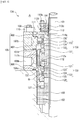
mechanical seal device 4 is of the so-called tandem type, where a primary-sidemechanical seal 20 and secondary-sidemechanical seal 30 are used to axially seal between a rotatingshaft 1 extending in the vertical direction and aseal cover 5 enclosing therotating shaft 1. A pump impeller (not illustrated) housed in an equipmentmain body 2 is fixed to the bottom of the rotatingshaft 1. Theseal cover 5 is fixed to the equipmentmain body 2 by abolt 9 andnut 10 and encloses the rotatingshaft 1 in the axial direction and radial direction. - The
seal cover 5 is formed by an axial-direction seal cover 6 which is fixed to the equipmentmain body 2 with thebolt 9 andnut 10 via agasket 6a, and an outer-diameter-side seal cover 7 and inner-diameter-side seal cover 8 which are connected to the end of the axial-direction seal cover 6 and seal in the radial direction. These seal covers 6, 7, 8 are formed by stainless steel, aluminum alloy, or other metal. - As shown in
FIG. 2 , the outer-diameter-side seal cover 7 has a circular cutout at the bottom on the inner diameter side, and also has acircular projection 7a formed at the top which projects toward the inner diameter side. The inner-diameter-side seal cover 8 has a circular cutout at the top on the outer diameter side, and also has acircular projection 8a (flange) formed at the bottom which projects toward the outer diameter side. When theprojection 7a of the outer-diameter-side seal cover 7 is aligned in position with the cutout in the inner-diameter-side seal cover 7, the outer-side surface of the outer-diameter-side seal cover 7 becomes roughly flush with that of the inner-diameter-side seal cover 8. When amale thread 11a of a coupling bolt 11 (fixing means) is caused to be screwed to afemale thread 8b of the inner-diameter-side seal cover 8, theprojection 7a is sandwiched between ahead 11b of thecoupling bolt 11 and theprojection 8a and is thus fixed in place. - When a bolt (not illustrated) is fastened via a
gasket 6b in a state where the outer-diameter-side seal cover 7 and inner-diameter-side seal cover 8 are coupled as one piece by thecoupling bolt 11, the outer-diameter-side seal cover 7 and inner-diameter-side seal cover 8 are fixed to the axial-direction seal cover 6. The inner-diameter-side seal cover 8 is sandwiched between theprojection 7a of the outer-diameter-side seal cover 7 and the top of the axial-direction seal cover 6. - A
setscrew 13 screwed with the female thread of acircular sleeve 13a fitting to asleeve 12, so that the tip of thesetscrew 13 abuts the outer periphery surface of the rotatingshaft 1 and thesleeve 12 does not rotate but remains fixed. Thecircular sleeve 13a is restrained by asplit ring 13c from moving outward in the axial direction. Asleeve collar 14 presses agasket 14a against the end face of thesleeve 12 to seal along the rotatingshaft 1. The primary-sidemechanical seal 20 comprises: amating ring 21 which is closely fitted and fixed via a retainer to the bottom outer periphery of thesleeve 12 and rotates with the rotatingshaft 1; a fixed-side seal ring 23 that slidably contacts themating ring 21; aretainer 24 that holds theseal ring 23 in place; abellows 25 which is welded and fixed to theretainer 24 and adds bias force in the axial direction; and anadapter 26 whose one end is welded and fixed to thebellows 25 and other end is fixed by abolt 27 to the bottom surface of the circular projection projecting toward the inner diameter side of the axial-direction seal cover 6. It should be noted that theseal ring 23,retainer 24,bellows 25, andadapter 26 constitute a fixed-side seal assembly 22. - The secondary-side
mechanical seal 30 comprises: amating ring 31 which is closely fitted and fixed to the center outer periphery of thesleeve 12 and rotates with the rotatingshaft 10; a fixed-side seal ring 33 that slidably contacts themating ring 31; aretainer 34 that holds theseal ring 33 in place; abellows 35 which is welded and fixed to theretainer 34 and adds bias force in the axial direction; and anadapter 36 whose one end is welded and fixed to thebellows 35 and other end is welded and fixed, along its outer periphery, to the inner periphery of the inner-diameter-side seal cover 8. It should be noted that theseal ring 33,retainer 34,bellows 35, andadapter 36 constitute a fixed-side seal assembly 32. In other words, the fixed-side seal assembly 32 is connected to the inner-diameter-side seal cover 8 in a securely following manner. - The primary-side
mechanical seal 20 seals a liquid orgas 3 in the pump chamber (not illustrated) present below it, and this liquid orgas 3 is partly transferred to an outer periphery space C of the primary-sidemechanical seal 20 and circulated back therefrom toward the pump chamber side through a flushingdrain hole 6c (feed hole) in the axial-direction seal cover 6 for flushing. This way, the sealed sliding surface of the primary-sidemechanical seal 20 is lubricated/cooled. - Also,
external liquid 37 is sealed in an interim chamber B between the primary-sidemechanical seal 20 and secondary-sidemechanical seal 30, filling the chamber to its top. Provided downward of the axial-direction seal cover 6 is an inlet hole (not illustrated) which connects to the interim chamber B housing the primary-sidemechanical seal 20 and through which theexternal liquid 37 flows in from the outside, while provided upward of it is anoutlet hole 6d (feed hole) which connects to the interim chamber B housing the secondary-sidemechanical seal 30 and through which theexternal liquid 37 flows out to the outside, and theexternal liquid 37 keeps the interim chamber B at a desired pressure. Also, theexternal liquid 37 is circulated by an impeller formed on thesleeve 12. - Next, maintenance of the
seal ring 33, etc., is explained.
(Step 1) As a preparation, the liquid orgas 3 in the pump chamber is drained and theexternal liquid 37 in the interim chamber B is drained from a drain port (not illustrated). With a set plate (not illustrated) engaging with aconcave part 13b of thecircular sleeve 13a, the set plate is installed to the outer-diameter-side seal cover 7 by a set plate bolt (not illustrated), after which thesetscrew 13 andnut 10 are removed and themechanical seal device 4 is removed from the equipmentmain body 2. - It should be noted that, by installing the set plate, the outer-diameter-
side seal cover 7 is fixed to thesleeve 12 via thecircular sleeve 13a and splitring 13c, and the primary-sidemechanical seal 20 and secondary-sidemechanical seal 30 can now be assembled into a cartridge structure having the same mode for use as that shown inFIG. 1 .
(Step 2) The set plate bolt is loosened and the set plate is removed, and thesplit ring 13c andsleeve collar 14 are removed, as well.
(Step 3) Thenut 10 and bolt (not illustrated) are removed, and while holding the outer-diameter-side seal cover 7, the outer-diameter-side seal cover 7, inner-diameter-side seal cover 8 and fixed-side seal assembly 32 are pulled out upward in the axial direction (toward atmosphere A).FIG. 2 shows the state after these have been pulled out.
(Step 4) Thecoupling bolt 11 is loosened and the outer-diameter-side seal cover 7 is removed from the inner-diameter-side seal cover 8.FIG. 3 shows the state after the seal cover has been removed.
(Step 5) Maintenance of the fixed-side seal assembly 32 is performed, such as repairing theseal ring 33.
(Step 6) Steps 1 to 5 above are performed in the reverse order to restore the original state. - Since the inner-diameter-
side seal cover 8 is detachably connected to the outer-diameter-side seal cover 7 as described above, the outer-diameter-side seal cover 7 can be removed from the inner-diameter-side seal cover 8 to which theseal ring 31 is connected. Because of this, the fixed-side seal assembly 32 having theseal ring 33 connected to the inner-diameter-side seal cover 8 via thebellows 35 becomes smaller in outer shape and lighter in weight, resulting in excellent ease of handling theseal ring 33, etc., during maintenance. Furthermore, if a need arises to replace the fixed-side seal assembly 32, the outer-diameter-side seal cover 7 can be removed from the assembly shown inFIG. 2 and this eliminates the need to replace the outer-diameter-side seal cover 7, and because all that is needed is to replace the fixed-side seal assembly 32 and inner-diameter-side seal cover 32, excellent economy is achieved. - Also, the outer-diameter-
side seal cover 7 and inner-diameter-side seal cover 8 have no feed hole for external liquid or other fluid, which eliminates the need to elongate the outer-diameter-side seal cover 7 and inner-diameter-side seal cover 8 in the axial direction so that they can be made small/lightweight as a result, and this leads to excellent ease of handling the outer-diameter-side seal cover and inner-diameter-side seal cover when they are removed from the axial-direction seal cover together. - In addition, because the outer-diameter-
side seal cover 7 and inner-diameter-side seal cover 8 are connected/arranged by the so-called half-lap joining method, and also because thecircular projection 7a of the outer-diameter-side seal cover 7 is sandwiched between thecircular projection 8a of the inner-diameter-side seal cover and thehead 11b of thecoupling bolt 11 fastened to the exterior side of the inner-diameter-side seal cover 8 and thereby fixed in place, thecoupling bolt 11 can be fastened to the inner-diameter-side seal cover 8 without causing theprojection 7a of the outer-diameter-side seal cover 7 to penetrate through, which allows the inner-diameter-side seal cover 8 to be constituted shorter in the axial direction and lighter. Moreover, because the internal pressure exerted by theexternal liquid 37 onto the inner-diameter-side seal cover 8 is primarily received by theprojection 7a of the outer-diameter-side seal cover 8, the fastening force by thecoupling bolt 11 can be low. Furthermore, since the inner-diameter-side seal cover 8 is sandwiched between the outer-diameter-side seal cover 7 and axial-direction seal cover 6 in the axial direction besides being fixed by a connecting member which is thecoupling bolt 11, the connectingmember 11 to be used can be one of low fastening force. - Furthermore, because the inner-diameter-
side seal cover 8 and outer-diameter-side seal cover 7 can be made shorter in the axial direction (made thinner), the axial-direction seal cover 6 can be extended higher (formed longer in the axial direction), which in rotate increases the degree of freedom of selecting the location of theoutlet hole 6d in the axial-direction seal cover 6. When a longitudinal pump is used, theoutlet hole 6d can be placed even higher to keep gas from collecting above the interim chamber B. - The mechanical seal pertaining to Example 2 is explained by referring to
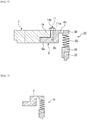
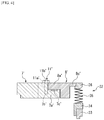
FIG. 4 which corresponds toFIG. 2 in Example 1. Example 2 differs from Example 1 in the shapes of the outer-diameter-side seal cover and inner-diameter-side seal cover and their connection structure, and these items different from Example 1 are explained below. - As shown in
FIG. 4 , an outer-diameter-side seal cover 7' has a circular cutout at the top on the inner diameter side, and also has acircular projection 7a' formed at the bottom which projects toward the inner diameter side. An inner-diameter-side seal cover 8' has a circular cutout at the bottom on the outer diameter side, and also has acircular projection 8a' (flange) formed at the top which projects toward the inner diameter side. When theprojection 7a' of the outer-diameter-side seal cover 7' is aligned in position with the cutout in the inner-diameter-side seal cover, the outer-side surface of the outer-diameter-side seal cover 7' becomes roughly flush with that of the inner-diameter-side seal cover 8'. When agasket 7c' (replacing thegasket 6b in Example 1) is placed between theprojection 7a' of the outer-diameter-side seal cover 7' and the cutout in the inner-diameter-side seal cover and amale thread 11a' of a coupling bolt 11' (fixing means) is caused to be screwed to afemale thread 7b' of the outer-diameter-side seal cover 7', theprojection 8a' is sandwiched between a head 11b' of the coupling bolt 11' and theprojection 7a' and thus fixed in place. - Because the outer-diameter-side seal cover 7' and inner-diameter-side seal cover 8' are connected/arranged by the so-called half-lap joining method, and also because the
circular projection 8a' of the inner-diameter-side seal cover 8' is sandwiched between thecircular projection 7a' of the outer-diameter-side seal cover 7' and thehead 11b' of the coupling bolt 11' fastened to the exterior side of the outer-diameter-side seal cover 7' and thereby fixed in place, as described above, the coupling bolt 11' can be fastened to the outer-diameter-side seal cover 7' without causing theprojection 8a' of the inner-diameter-side seal cover 8' to penetrate through, which allows the outer-diameter-side seal cover 7' to be constituted shorter in the axial direction and lighter, while also achieving excellent ease of maintenance because the inner-diameter-side seal cover 8' can be removed without removing the outer-diameter-side seal cover 7'. - The mechanical seal device pertaining to Example 3 is explained by referring to
FIGS. 5 to 7 . In the explanations below, the top and bottom ofFIG. 5 represent the top and bottom of the mechanical seal device, while the inner side and atmosphere side of the mechanical seal device represent the inner side and outer side, respectively. - A
mechanical seal device 104 is of the so-called back-to-back double type, where a primary-sidemechanical seal 120 and secondary-sidemechanical seal 130 are used to axially seal between arotating shaft 101 extending in the vertical direction and aseal cover 105 enclosing therotating shaft 101. A pump impeller housed in an equipmentmain body 102 is fixed to the bottom of therotating shaft 101. Theseal cover 105 is fixed to the equipmentmain body 102 by abolt 109 andnut 110 and encloses therotating shaft 101 in the axial direction and radial direction. - The
seal cover 105 is formed by an axial-direction seal cover 106 which is fixed to the equipmentmain body 102 with thebolt 109 andnut 110 via agasket 106a, and an outer-diameter-side seal cover 107 and inner-diameter-side seal cover 108 which are connected to the end of the axial-direction seal cover 106 and seal in the radial direction. These seal covers 106, 107, 108 are formed by stainless steel, aluminum alloy, or other metal. - As shown in
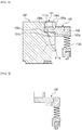
FIG. 6 , the outer-diameter-side seal cover 107 has a circular cutout at the top on the inner diameter side (end face side on the atmosphere A side), and also has acircular projection 107a formed below the cutout and projecting toward the inner diameter side. The inner-diameter-side seal cover 108 has a circular cutout at the bottom on the outer diameter side, and also has acircular projection 108a (flange) formed above the cutout and projecting toward the outer diameter side, and acounter bore 108d to accommodate ahead 111b of a coupling bolt 111 (fixing means) is formed in thecircular projection 108a. With acircular gasket 108e placed between the side faces of theprojections projection 107a of the outer-diameter-side seal cover 107 is aligned in position with the cutout in the inner-diameter-side seal cover and then thecoupling bolt 111 is guided from above through a throughhole 108b provided in theprojection 108a and through hole in thegasket 108e to cause amale thread 111a of thecoupling bolt 111 to be screwed to afemale thread 107c of theprojection 107a, so that the inner-diameter-side seal cover 108 is fixed to the outer-diameter-side seal cover 107 as a result. - The outer-diameter-
side seal cover 107 is fixed to the axial-direction seal cover 106 by fastening a bolt (not illustrated). The outer-diameter-side seal cover 107 and axial-direction seal cover 106 are sealed by agasket 107d. - A
setscrew 113 screwed with the female thread of acircular sleeve 113a fitting to asleeve 112, so that the tip of thesetscrew 113 abuts the outer periphery surface of therotating shaft 101 and thesleeve 112 does not rotate but remains fixed. Thecircular sleeve 113a is restrained by asplit ring 113c from moving outward in the axial direction. Also, asleeve collar 114 presses agasket 114a against the end face of thesleeve 112 to seal along therotating shaft 101. The primary-sidemechanical seal 120 comprises: amating ring 121 which is closely fitted and fixed to the bottom of acircular projection 112a of thesleeve 112 and rotates with therotating shaft 101; a fixed-side seal ring 123 that slidably contacts themating ring 121; aretainer 124 that holds theseal ring 123 in place; abellows 125 which is welded and fixed to theretainer 124 and adds bias force in the axial direction; and anadapter 126 whose one end is welded and fixed to thebellows 125 and other end is fixed by abolt 127 to the inner periphery of the axial-direction seal cover 106. It should be noted that theseal ring 123,retainer 124, bellows 125, andadapter 126 constitute a fixed-side seal assembly 122. - The secondary-side
mechanical seal 130 comprises: amating ring 131 which is closely fitted and fixed to the top of thecircular projection 112a of thesleeve 112 and rotates with therotating shaft 101; a fixed-side seal ring 133 that slidably contacts themating ring 131; aretainer 134 that holds theseal ring 133 in place; abellows 135 which is welded and fixed to theretainer 134 and adds bias force in the axial direction; and anadapter 136 whose one end is welded and fixed to thebellows 135 and other end is welded and fixed, along its outer periphery, to the inner periphery of the inner-diameter-side seal cover 108. It should be noted that theseal ring 133,retainer 134, bellows 135, andadapter 136 constitute a fixed-side seal assembly 132. In other words, the fixed-side seal assembly 132 is connected to the inner-diameter-side seal cover 108 in a securely following manner. - Also,
external liquid 137 is sealed in an interim chamber B between the primary-sidemechanical seal 120 and secondary-sidemechanical seal 130, filling the chamber to its top. Provided downward of the axial-direction seal cover 106 is aninlet hole 106b (feed hole) which connects to the interim chamber B housing the primary-sidemechanical seal 120 and through which theexternal liquid 137 flows in from the outside, while provided roughly at the center of the outer-diameter-side seal cover 107 in the vertical direction is anoutlet hole 107b which connects to the interim chamber B housing the secondary-sidemechanical seal 130 and through which theexternal liquid 137 flows out to the outside, and theexternal liquid 137 keeps the interim chamber B at a desired pressure. Also, theexternal liquid 137 is circulated by animpeller 112b provided on thesleeve 112. - Next, maintenance of the
seal ring 133, etc., is explained.
(Step 1) As a preparation, a liquid orgas 103 in the pump chamber is drained and theexternal liquid 137 in the interim chamber B is drained from a drain port (not illustrated). With a set plate (not illustrated) engaging with aconcave part 113b of thecircular sleeve 113a, the set plate is installed to the outer-diameter-side seal cover 107 by a set plate bolt (not illustrated), after which thesetscrew 113 andnut 110 are removed and themechanical seal device 104 is removed from the equipmentmain body 102. - It should be noted that, by installing the set plate, the outer-diameter-
side seal cover 107 is fixed to thesleeve 112 via thecircular sleeve 113a and splitring 113c, and the primary-sidemechanical seal 120 and secondary-sidemechanical seal 130 can now be assembled into a cartridge structure having the same mode for use as that shown inFIG. 1 .
(Step 2) The set plate bolt is loosened and the set plate is removed, and thesplit ring 113c andsleeve collar 114 are removed, as well.
(Step 3) Thecoupling bolt 111 is loosened and the outer-diameter-side seal cover 107 is removed from the inner-diameter-side seal cover 108.FIG. 7 shows the state after the seal cover has been removed.
(Step 4) Maintenance of the fixed-side seal assembly 132 is performed, such as repairing theseal ring 133.
(Step 5) Steps 1 to 4 above are performed in the reverse order to restore the original state. - Since the inner-diameter-
side seal cover 108 is detachably connected to the outer-diameter-side seal cover 107 as described above, the outer-diameter-side seal cover 107 can be removed from the inner-diameter-side seal cover 108 to which theseal ring 131 is connected. The fixed-side seal assembly 132 having theseal ring 133 connected to the inner-diameter-side seal cover 108 via thebellows 135 becomes smaller in outer shape and lighter in weight, resulting in excellent ease of handling theseal ring 133, etc., during maintenance. Furthermore, if a need arises to replace the fixed-side seal assembly 132, the outer-diameter-side seal cover 107 can be removed from the assembly shown inFIG. 6 and this eliminates the need to replace the outer-diameter-side seal cover 107, and because all that is needed is to replace the fixed-side seal assembly 132 and inner-diameter-side seal cover 108, excellent economy is achieved. - Also, the inner-diameter-
side seal cover 108 has no feed hole for external liquid or other fluid and theoutlet hole 107b is provided in the outer-diameter-side seal cover 107 extending to the top, which increases the degree of freedom of selecting the location of theoutlet hole 107b. When a longitudinal pump is used, theoutlet hole 107b can be placed even higher to keep gas from collecting above the interim chamber B. - Furthermore, because the
circular projection 108a of the inner-diameter-side seal cover 108 is provided above (on the atmosphere A side of) thecircular projection 107a of the outer-diameter-side seal cover 107, the inner-diameter-side seal cover 108 and fixed-side seal assembly 132 can be removed simply by loosening thecoupling bolt 111, without loosening thenut 110 instep 3 above, or specifically with the outer-diameter-side seal cover 107 still fixed to the axial-direction seal cover 106.FIG. 7 shows the state after these have been removed. - The foregoing explained the examples of the present invention using the drawings; however, specific constitutions are not limited to these examples and other modifications and additions are also included in the scope of the present invention so long as they do not deviate from the main points of the present invention.
- For example, the foregoing explained a fixed-side seal assembly having a seal ring, retainer, bellows, and adapter; however, any fixed-side seal assembly may be used so long as it has at least a seal ring. In other words, any fixed-side seal assembly may be used so long as a seal ring is connected to its inner-diameter-side seal cover.
- In addition, while desirably the outer-diameter-
side seal cover side seal cover - Also, while the foregoing explained mechanical seal devices of the tandem type and double type, other types of mechanical seal devices are also supported.
-
- 1
- Rotating shaft
- 2
- Equipment main body
- 4
- Mechanical seal device
- 5
- Seal cover
- 6
- Axial-direction seal cover
- 6c
- Flushing drain hole (feed hole)
- 6d
- Outlet hole (feed hole)
- 7, 7'
- Outer-diameter-side seal cover
- 7a, 7a'
- Circular projection
- 8, 8'
- Inner-diameter-side seal cover
- 8a, 8a'
- Circular projection (flange)
- 11, 11'
- Coupling bolt (fixing means)
- 11b, 11b'
- Head
- 20
- Primary-side mechanical seal
- 21
- Mating ring
- 22
- Fixed-side seal assembly
- 23
- Seal ring
- 25
- Bellows
- 30
- Secondary-side mechanical seal
- 31
- Mating ring
- 32
- Fixed-side seal assembly
- 33
- Seal ring
- 35
- Bellows
- 101
- Rotating shaft
- 102
- Equipment main body
- 104
- Mechanical seal device
- 105
- Seal cover
- 106
- Axial-direction seal cover
- 106b
- Inlet hole (feed hole)
- 107
- Outer-diameter-side seal cover
- 107a
- Circular projection
- 108
- Inner-diameter-side seal cover
- 108a
- Circular projection (flange)
- 111
- Coupling bolt (fixing means)
- 111b
- Head
- 120
- Primary-side mechanical seal
- 121
- Mating ring
- 122
- Fixed-side seal assembly
- 123
- Seal ring
- 125
- Bellows
- 130
- Secondary-side mechanical seal
- 131
- Mating ring
- 132
- Fixed-side seal assembly
- 133
- Seal ring
- 135
- Bellows
Claims (5)
- A mechanical seal device having a mating ring that rotates with a rotating shaft, as well as a seal ring that slidably contacts the mating ring, so as to seal between the rotating shaft and a seal cover fixed to an equipment main body;
the mechanical seal device characterized in that the seal cover is a split structure comprising at least an inner-diameter-side seal cover and an outer-diameter-side seal cover, the inner-diameter-side seal cover is detachably connected to the outer-diameter-side seal cover, and the seal ring is connected to the inner-diameter-side seal cover in a securely following manner. - A mechanical seal device according to Claim 1, characterized in that the seal cover is a three-part split structure comprising at least the inner-diameter-side seal cover, outer-diameter-side seal cover, and an axial-direction seal cover, wherein the inner-diameter-side seal cover, outer-diameter-side seal cover, and axial-direction seal cover are each detachably connected, and a feed hole is provided in the axial-direction seal cover through which fluid is fed from outside into a space where the seal ring is placed.
- A mechanical seal device according to Claim 1 or 2, characterized in that a flange is formed on the inner-diameter-side seal cover, and the inner-diameter-side seal cover is fixed to the outer-diameter-side seal cover by a fixing means in a state where the flange is abutting an inner side of the outer-diameter-side seal cover in an axial direction.
- A mechanical seal device according to Claim 3, characterized in that the fixing means is a coupling bolt with head which is installed on the inner-diameter-side seal cover, from an outer side in the axial direction, at a position on an inner diameter side of the outer-diameter-side seal cover, and a part of the head of the coupling bolt contacts the outer-side seal cover.
- A mechanical seal device according to Claim 3 or 4, characterized in that the fixing means provides fixing in which the flange of the inner-diameter-side seal cover is sandwiched between the outer-diameter-side seal cover and axial-direction seal cover in the axial direction.
Applications Claiming Priority (2)
| Application Number | Priority Date | Filing Date | Title |
|---|---|---|---|
| JP2014224147 | 2014-11-04 | ||
| PCT/JP2015/080219 WO2016072318A1 (en) | 2014-11-04 | 2015-10-27 | Mechanical sealing device |
Publications (3)
| Publication Number | Publication Date |
|---|---|
| EP3217048A1 true EP3217048A1 (en) | 2017-09-13 |
| EP3217048A4 EP3217048A4 (en) | 2018-07-18 |
| EP3217048B1 EP3217048B1 (en) | 2020-09-16 |
Family
ID=55909044
Family Applications (1)
| Application Number | Title | Priority Date | Filing Date |
|---|---|---|---|
| EP15857687.6A Active EP3217048B1 (en) | 2014-11-04 | 2015-10-27 | Mechanical sealing device |
Country Status (5)
| Country | Link |
|---|---|
| US (1) | US10145475B2 (en) |
| EP (1) | EP3217048B1 (en) |
| JP (1) | JP6537524B2 (en) |
| CN (1) | CN107076307B (en) |
| WO (1) | WO2016072318A1 (en) |
Family Cites Families (41)
| Publication number | Priority date | Publication date | Assignee | Title |
|---|---|---|---|---|
| US3526408A (en) * | 1969-01-02 | 1970-09-01 | Borg Warner | Mechanical seal construction |
| US3746349A (en) | 1970-08-26 | 1973-07-17 | F Robson | Mechanical seals and or thrust bearings |
| JPS5642538Y2 (en) * | 1976-05-21 | 1981-10-05 | ||
| GB2123098B (en) * | 1982-07-01 | 1985-12-18 | Aes Eng Ltd | Mechanical shaft seals |
| US5067733A (en) * | 1987-07-31 | 1991-11-26 | Tanken Seiko Kabushiki Kaisha | Mechanical seal including a split seal ring |
| JPH0636364Y2 (en) * | 1989-12-26 | 1994-09-21 | イーグル工業株式会社 | Quenching mechanism of slurry seal |
| JPH0659668A (en) | 1992-08-07 | 1994-03-04 | Brother Ind Ltd | Automatic transcription device for rhythm instruments |
| DE29600707U1 (en) | 1996-01-17 | 1996-03-07 | Feodor Burgmann Dichtungswerke GmbH & Co, 82515 Wolfratshausen | Sealing arrangement |
| US5658127A (en) | 1996-01-26 | 1997-08-19 | Sundstrand Corporation | Seal element cooling in high speed mechanical face seals |
| GB9707754D0 (en) * | 1997-04-17 | 1997-06-04 | Aes Eng Ltd | Mechanical seal |
| EP1031775A1 (en) * | 1999-02-25 | 2000-08-30 | Dresser Rand S.A | Shaft seal |
| US6325382B1 (en) | 1999-05-21 | 2001-12-04 | Nippon Pillar Packing Co., Ltd. | Non-contact type mechanical seal |
| AUPQ135799A0 (en) * | 1999-07-01 | 1999-07-22 | M.I.M. Holdings Limited | Mechanical shaft to housing seal |
| US6685191B2 (en) | 2000-02-11 | 2004-02-03 | A. W. Chesterton Company | Mechanical seal for rotating shaft |
| JP4111698B2 (en) * | 2001-08-31 | 2008-07-02 | イーグル工業株式会社 | Mechanical seal device |
| AU2002365995A1 (en) | 2001-11-22 | 2003-06-10 | Mitsubishi Chemical Corporation | Method and device for feeding polymerization liquid |
| JP3792205B2 (en) | 2003-03-03 | 2006-07-05 | 日本ピラー工業株式会社 | mechanical seal |
| US7987312B2 (en) * | 2004-07-30 | 2011-07-26 | Via Technologies, Inc. | Method and apparatus for dynamically determining bit configuration |
| GB0423087D0 (en) * | 2004-10-18 | 2004-11-17 | Aes Eng Ltd | Close coupled mechanical seal |
| JP5225675B2 (en) | 2005-04-28 | 2013-07-03 | イーグル工業株式会社 | Mechanical seal device |
| FI117300B (en) * | 2005-04-29 | 2006-08-31 | Sulzer Pumpen Ag | Flow Machine, Slip Ring Gasket, Slip Gasket Body and Method for Attaching Slip Ring Gasket to Flow Machine |
| SE531613C2 (en) | 2005-06-27 | 2009-06-09 | Huhnseal Ab | sealing device |
| EP1950475B1 (en) | 2005-11-17 | 2013-01-09 | Eagle Industry Co., Ltd. | Mechanical seal device |
| WO2008013147A1 (en) | 2006-07-25 | 2008-01-31 | Eagle Industry Co., Ltd. | Mechanical seal device |
| DE102007002644A1 (en) | 2007-01-12 | 2008-07-17 | Aumüller, Hermann | Stern tube seal, has housing fastened at stern tube and surrounding drive shaft, and sliding ring consisting softer material lying in holder and held in holder in removable manner by retaining units i.e. 0-rings |
| DE202008009842U1 (en) * | 2008-07-22 | 2008-09-18 | Burgmann Industries Gmbh & Co. Kg | Mechanical seal arrangement with filter element |
| KR20100103015A (en) * | 2009-03-12 | 2010-09-27 | 엘지이노텍 주식회사 | Lead frame and method for manufacturing the same |
| AU2010225452B2 (en) * | 2009-03-16 | 2016-06-09 | Vulco S.A. | Mechanical seal |
| EP2416037B1 (en) | 2009-03-30 | 2013-09-04 | Eagle Industry Co., Ltd. | Bellows type mechanical seal |
| US8517388B2 (en) * | 2009-03-31 | 2013-08-27 | Eagle Industry Co., Ltd. | Bellows type mechanical seal |
| WO2010123025A1 (en) | 2009-04-23 | 2010-10-28 | イーグル工業株式会社 | Mechanical seal device |
| TW201043814A (en) * | 2009-06-05 | 2010-12-16 | Scenic Precise Element Inc | Shaft seal |
| JP5153731B2 (en) * | 2009-07-08 | 2013-02-27 | 日本ピラー工業株式会社 | mechanical seal |
| CN102112785B (en) | 2009-09-24 | 2014-12-03 | 伊格尔工业股份有限公司 | Mechanical seal |
| JP5396615B2 (en) | 2009-10-02 | 2014-01-22 | イーグル工業株式会社 | Mechanical seal device |
| CN102472393B (en) * | 2009-10-30 | 2015-01-07 | 伊格尔工业股份有限公司 | Mechanical seal |
| WO2011122256A1 (en) * | 2010-03-31 | 2011-10-06 | イーグル工業株式会社 | Pipe connection mechanism for a sealing device, and mechanical sealing device |
| US20130223782A1 (en) | 2010-07-26 | 2013-08-29 | Aktiebolaget Skf | Mechanical face seal assembly for bearings |
| JP6124901B2 (en) * | 2012-08-29 | 2017-05-10 | イーグル工業株式会社 | mechanical seal |
| CN103821942A (en) | 2013-07-03 | 2014-05-28 | 东营海森密封技术有限责任公司 | Double mechanical sealing method and double mechanical sealing device for kettle gas films |
| CN203770641U (en) * | 2013-12-26 | 2014-08-13 | 东莞市华汇精密机械有限公司 | Double-end-face corrugated-pipe sealing device for ball mill |
-
2015
- 2015-10-27 US US15/521,610 patent/US10145475B2/en active Active
- 2015-10-27 EP EP15857687.6A patent/EP3217048B1/en active Active
- 2015-10-27 JP JP2016557721A patent/JP6537524B2/en active Active
- 2015-10-27 CN CN201580058486.7A patent/CN107076307B/en active Active
- 2015-10-27 WO PCT/JP2015/080219 patent/WO2016072318A1/en not_active Ceased
Also Published As
| Publication number | Publication date |
|---|---|
| JPWO2016072318A1 (en) | 2017-08-17 |
| EP3217048A4 (en) | 2018-07-18 |
| US10145475B2 (en) | 2018-12-04 |
| WO2016072318A1 (en) | 2016-05-12 |
| CN107076307A (en) | 2017-08-18 |
| CN107076307B (en) | 2019-06-21 |
| US20170241548A1 (en) | 2017-08-24 |
| EP3217048B1 (en) | 2020-09-16 |
| JP6537524B2 (en) | 2019-07-03 |
Similar Documents
| Publication | Publication Date | Title |
|---|---|---|
| US20240167592A1 (en) | Adapter Coupling | |
| US9534715B2 (en) | Coupling gasket with multiple sealing surfaces | |
| EP3217047A1 (en) | Mechanical seal device | |
| CN107461556A (en) | Flange connecting assembly and its handling method, pipeline connecting device and cooler unit | |
| CN102418821A (en) | hose connecting sleeve | |
| GB2506148A (en) | Flange assembly | |
| US20040160055A1 (en) | Pipe seal | |
| US10145475B2 (en) | Mechanical seal device | |
| JP2006153180A (en) | Fluid gasket | |
| JP2006226476A (en) | Man-hole sealing structure for pressure vessel | |
| JP2006083972A (en) | Connection structure of mutual flange pipes and connection construction of flange pipe and fluid apparatus | |
| KR101889235B1 (en) | Sealing device | |
| US9261210B2 (en) | Pipe connector | |
| CN113217723B (en) | Flange connection sealing structure | |
| JP5208686B2 (en) | Desorption device for pipe connecting member | |
| CN202048257U (en) | Stainless steel male end ball valve | |
| WO2017030182A1 (en) | Turbo device | |
| JP2016095029A (en) | Method for fastening seal washer and fluid pipe flange | |
| KR102918614B1 (en) | A rotor assembly of a gas turbine engine | |
| JP5914028B2 (en) | Detachment prevention device | |
| AU2018353673A1 (en) | Pump, pump device, and method of disassembling pump device | |
| JP2019007527A (en) | Tubular structure | |
| KR20130082295A (en) | Nozzle and mounting method thereof | |
| CN104048120A (en) | Pressure binding type pipe joint | |
| JP5208687B2 (en) | Desorption device for pipe connecting member |
Legal Events
| Date | Code | Title | Description |
|---|---|---|---|
| STAA | Information on the status of an ep patent application or granted ep patent |
Free format text: STATUS: THE INTERNATIONAL PUBLICATION HAS BEEN MADE |
|
| PUAI | Public reference made under article 153(3) epc to a published international application that has entered the european phase |
Free format text: ORIGINAL CODE: 0009012 |
|
| STAA | Information on the status of an ep patent application or granted ep patent |
Free format text: STATUS: REQUEST FOR EXAMINATION WAS MADE |
|
| 17P | Request for examination filed |
Effective date: 20170605 |
|
| AK | Designated contracting states |
Kind code of ref document: A1 Designated state(s): AL AT BE BG CH CY CZ DE DK EE ES FI FR GB GR HR HU IE IS IT LI LT LU LV MC MK MT NL NO PL PT RO RS SE SI SK SM TR |
|
| AX | Request for extension of the european patent |
Extension state: BA ME |
|
| DAV | Request for validation of the european patent (deleted) | ||
| DAX | Request for extension of the european patent (deleted) | ||
| A4 | Supplementary search report drawn up and despatched |
Effective date: 20180619 |
|
| RIC1 | Information provided on ipc code assigned before grant |
Ipc: F16J 15/34 20060101AFI20180613BHEP |
|
| GRAP | Despatch of communication of intention to grant a patent |
Free format text: ORIGINAL CODE: EPIDOSNIGR1 |
|
| STAA | Information on the status of an ep patent application or granted ep patent |
Free format text: STATUS: GRANT OF PATENT IS INTENDED |
|
| INTG | Intention to grant announced |
Effective date: 20200527 |
|
| GRAS | Grant fee paid |
Free format text: ORIGINAL CODE: EPIDOSNIGR3 |
|
| GRAA | (expected) grant |
Free format text: ORIGINAL CODE: 0009210 |
|
| STAA | Information on the status of an ep patent application or granted ep patent |
Free format text: STATUS: THE PATENT HAS BEEN GRANTED |
|
| AK | Designated contracting states |
Kind code of ref document: B1 Designated state(s): AL AT BE BG CH CY CZ DE DK EE ES FI FR GB GR HR HU IE IS IT LI LT LU LV MC MK MT NL NO PL PT RO RS SE SI SK SM TR |
|
| REG | Reference to a national code |
Ref country code: GB Ref legal event code: FG4D |
|
| REG | Reference to a national code |
Ref country code: CH Ref legal event code: EP |
|
| REG | Reference to a national code |
Ref country code: DE Ref legal event code: R096 Ref document number: 602015059322 Country of ref document: DE |
|
| REG | Reference to a national code |
Ref country code: IE Ref legal event code: FG4D |
|
| REG | Reference to a national code |
Ref country code: AT Ref legal event code: REF Ref document number: 1314455 Country of ref document: AT Kind code of ref document: T Effective date: 20201015 |
|
| PG25 | Lapsed in a contracting state [announced via postgrant information from national office to epo] |
Ref country code: BG Free format text: LAPSE BECAUSE OF FAILURE TO SUBMIT A TRANSLATION OF THE DESCRIPTION OR TO PAY THE FEE WITHIN THE PRESCRIBED TIME-LIMIT Effective date: 20201216 Ref country code: HR Free format text: LAPSE BECAUSE OF FAILURE TO SUBMIT A TRANSLATION OF THE DESCRIPTION OR TO PAY THE FEE WITHIN THE PRESCRIBED TIME-LIMIT Effective date: 20200916 Ref country code: SE Free format text: LAPSE BECAUSE OF FAILURE TO SUBMIT A TRANSLATION OF THE DESCRIPTION OR TO PAY THE FEE WITHIN THE PRESCRIBED TIME-LIMIT Effective date: 20200916 Ref country code: FI Free format text: LAPSE BECAUSE OF FAILURE TO SUBMIT A TRANSLATION OF THE DESCRIPTION OR TO PAY THE FEE WITHIN THE PRESCRIBED TIME-LIMIT Effective date: 20200916 Ref country code: GR Free format text: LAPSE BECAUSE OF FAILURE TO SUBMIT A TRANSLATION OF THE DESCRIPTION OR TO PAY THE FEE WITHIN THE PRESCRIBED TIME-LIMIT Effective date: 20201217 Ref country code: NO Free format text: LAPSE BECAUSE OF FAILURE TO SUBMIT A TRANSLATION OF THE DESCRIPTION OR TO PAY THE FEE WITHIN THE PRESCRIBED TIME-LIMIT Effective date: 20201216 |
|
| REG | Reference to a national code |
Ref country code: AT Ref legal event code: MK05 Ref document number: 1314455 Country of ref document: AT Kind code of ref document: T Effective date: 20200916 |
|
| REG | Reference to a national code |
Ref country code: NL Ref legal event code: MP Effective date: 20200916 |
|
| PG25 | Lapsed in a contracting state [announced via postgrant information from national office to epo] |
Ref country code: LV Free format text: LAPSE BECAUSE OF FAILURE TO SUBMIT A TRANSLATION OF THE DESCRIPTION OR TO PAY THE FEE WITHIN THE PRESCRIBED TIME-LIMIT Effective date: 20200916 Ref country code: RS Free format text: LAPSE BECAUSE OF FAILURE TO SUBMIT A TRANSLATION OF THE DESCRIPTION OR TO PAY THE FEE WITHIN THE PRESCRIBED TIME-LIMIT Effective date: 20200916 |
|
| REG | Reference to a national code |
Ref country code: LT Ref legal event code: MG4D |
|
| PG25 | Lapsed in a contracting state [announced via postgrant information from national office to epo] |
Ref country code: EE Free format text: LAPSE BECAUSE OF FAILURE TO SUBMIT A TRANSLATION OF THE DESCRIPTION OR TO PAY THE FEE WITHIN THE PRESCRIBED TIME-LIMIT Effective date: 20200916 Ref country code: RO Free format text: LAPSE BECAUSE OF FAILURE TO SUBMIT A TRANSLATION OF THE DESCRIPTION OR TO PAY THE FEE WITHIN THE PRESCRIBED TIME-LIMIT Effective date: 20200916 Ref country code: SM Free format text: LAPSE BECAUSE OF FAILURE TO SUBMIT A TRANSLATION OF THE DESCRIPTION OR TO PAY THE FEE WITHIN THE PRESCRIBED TIME-LIMIT Effective date: 20200916 Ref country code: PT Free format text: LAPSE BECAUSE OF FAILURE TO SUBMIT A TRANSLATION OF THE DESCRIPTION OR TO PAY THE FEE WITHIN THE PRESCRIBED TIME-LIMIT Effective date: 20210118 Ref country code: LT Free format text: LAPSE BECAUSE OF FAILURE TO SUBMIT A TRANSLATION OF THE DESCRIPTION OR TO PAY THE FEE WITHIN THE PRESCRIBED TIME-LIMIT Effective date: 20200916 Ref country code: CZ Free format text: LAPSE BECAUSE OF FAILURE TO SUBMIT A TRANSLATION OF THE DESCRIPTION OR TO PAY THE FEE WITHIN THE PRESCRIBED TIME-LIMIT Effective date: 20200916 |
|
| PG25 | Lapsed in a contracting state [announced via postgrant information from national office to epo] |
Ref country code: AL Free format text: LAPSE BECAUSE OF FAILURE TO SUBMIT A TRANSLATION OF THE DESCRIPTION OR TO PAY THE FEE WITHIN THE PRESCRIBED TIME-LIMIT Effective date: 20200916 Ref country code: AT Free format text: LAPSE BECAUSE OF FAILURE TO SUBMIT A TRANSLATION OF THE DESCRIPTION OR TO PAY THE FEE WITHIN THE PRESCRIBED TIME-LIMIT Effective date: 20200916 Ref country code: ES Free format text: LAPSE BECAUSE OF FAILURE TO SUBMIT A TRANSLATION OF THE DESCRIPTION OR TO PAY THE FEE WITHIN THE PRESCRIBED TIME-LIMIT Effective date: 20200916 Ref country code: PL Free format text: LAPSE BECAUSE OF FAILURE TO SUBMIT A TRANSLATION OF THE DESCRIPTION OR TO PAY THE FEE WITHIN THE PRESCRIBED TIME-LIMIT Effective date: 20200916 Ref country code: IS Free format text: LAPSE BECAUSE OF FAILURE TO SUBMIT A TRANSLATION OF THE DESCRIPTION OR TO PAY THE FEE WITHIN THE PRESCRIBED TIME-LIMIT Effective date: 20210116 |
|
| REG | Reference to a national code |
Ref country code: CH Ref legal event code: PL |
|
| REG | Reference to a national code |
Ref country code: DE Ref legal event code: R097 Ref document number: 602015059322 Country of ref document: DE |
|
| PG25 | Lapsed in a contracting state [announced via postgrant information from national office to epo] |
Ref country code: SK Free format text: LAPSE BECAUSE OF FAILURE TO SUBMIT A TRANSLATION OF THE DESCRIPTION OR TO PAY THE FEE WITHIN THE PRESCRIBED TIME-LIMIT Effective date: 20200916 Ref country code: LU Free format text: LAPSE BECAUSE OF NON-PAYMENT OF DUE FEES Effective date: 20201027 Ref country code: MC Free format text: LAPSE BECAUSE OF FAILURE TO SUBMIT A TRANSLATION OF THE DESCRIPTION OR TO PAY THE FEE WITHIN THE PRESCRIBED TIME-LIMIT Effective date: 20200916 |
|
| REG | Reference to a national code |
Ref country code: BE Ref legal event code: MM Effective date: 20201031 |
|
| PLBE | No opposition filed within time limit |
Free format text: ORIGINAL CODE: 0009261 |
|
| STAA | Information on the status of an ep patent application or granted ep patent |
Free format text: STATUS: NO OPPOSITION FILED WITHIN TIME LIMIT |
|
| 26N | No opposition filed |
Effective date: 20210617 |
|
| GBPC | Gb: european patent ceased through non-payment of renewal fee |
Effective date: 20201216 |
|
| PG25 | Lapsed in a contracting state [announced via postgrant information from national office to epo] |
Ref country code: LI Free format text: LAPSE BECAUSE OF NON-PAYMENT OF DUE FEES Effective date: 20201031 Ref country code: SI Free format text: LAPSE BECAUSE OF FAILURE TO SUBMIT A TRANSLATION OF THE DESCRIPTION OR TO PAY THE FEE WITHIN THE PRESCRIBED TIME-LIMIT Effective date: 20200916 Ref country code: BE Free format text: LAPSE BECAUSE OF NON-PAYMENT OF DUE FEES Effective date: 20201031 Ref country code: DK Free format text: LAPSE BECAUSE OF FAILURE TO SUBMIT A TRANSLATION OF THE DESCRIPTION OR TO PAY THE FEE WITHIN THE PRESCRIBED TIME-LIMIT Effective date: 20200916 Ref country code: CH Free format text: LAPSE BECAUSE OF NON-PAYMENT OF DUE FEES Effective date: 20201031 |
|
| PG25 | Lapsed in a contracting state [announced via postgrant information from national office to epo] |
Ref country code: FR Free format text: LAPSE BECAUSE OF NON-PAYMENT OF DUE FEES Effective date: 20201116 Ref country code: IE Free format text: LAPSE BECAUSE OF NON-PAYMENT OF DUE FEES Effective date: 20201027 Ref country code: IT Free format text: LAPSE BECAUSE OF FAILURE TO SUBMIT A TRANSLATION OF THE DESCRIPTION OR TO PAY THE FEE WITHIN THE PRESCRIBED TIME-LIMIT Effective date: 20200916 |
|
| PG25 | Lapsed in a contracting state [announced via postgrant information from national office to epo] |
Ref country code: GB Free format text: LAPSE BECAUSE OF NON-PAYMENT OF DUE FEES Effective date: 20201216 |
|
| PG25 | Lapsed in a contracting state [announced via postgrant information from national office to epo] |
Ref country code: IS Free format text: LAPSE BECAUSE OF FAILURE TO SUBMIT A TRANSLATION OF THE DESCRIPTION OR TO PAY THE FEE WITHIN THE PRESCRIBED TIME-LIMIT Effective date: 20210116 Ref country code: TR Free format text: LAPSE BECAUSE OF FAILURE TO SUBMIT A TRANSLATION OF THE DESCRIPTION OR TO PAY THE FEE WITHIN THE PRESCRIBED TIME-LIMIT Effective date: 20200916 Ref country code: MT Free format text: LAPSE BECAUSE OF FAILURE TO SUBMIT A TRANSLATION OF THE DESCRIPTION OR TO PAY THE FEE WITHIN THE PRESCRIBED TIME-LIMIT Effective date: 20200916 Ref country code: CY Free format text: LAPSE BECAUSE OF FAILURE TO SUBMIT A TRANSLATION OF THE DESCRIPTION OR TO PAY THE FEE WITHIN THE PRESCRIBED TIME-LIMIT Effective date: 20200916 |
|
| PG25 | Lapsed in a contracting state [announced via postgrant information from national office to epo] |
Ref country code: MK Free format text: LAPSE BECAUSE OF FAILURE TO SUBMIT A TRANSLATION OF THE DESCRIPTION OR TO PAY THE FEE WITHIN THE PRESCRIBED TIME-LIMIT Effective date: 20200916 |
|
| PG25 | Lapsed in a contracting state [announced via postgrant information from national office to epo] |
Ref country code: NL Free format text: LAPSE BECAUSE OF NON-PAYMENT OF DUE FEES Effective date: 20200923 |
|
| PGFP | Annual fee paid to national office [announced via postgrant information from national office to epo] |
Ref country code: DE Payment date: 20250902 Year of fee payment: 11 |