EP1031775A1 - Shaft seal - Google Patents
Shaft seal Download PDFInfo
- Publication number
- EP1031775A1 EP1031775A1 EP99400460A EP99400460A EP1031775A1 EP 1031775 A1 EP1031775 A1 EP 1031775A1 EP 99400460 A EP99400460 A EP 99400460A EP 99400460 A EP99400460 A EP 99400460A EP 1031775 A1 EP1031775 A1 EP 1031775A1
- Authority
- EP
- European Patent Office
- Prior art keywords
- seal
- sleeve
- sealing
- pressure
- sealing element
- Prior art date
- Legal status (The legal status is an assumption and is not a legal conclusion. Google has not performed a legal analysis and makes no representation as to the accuracy of the status listed.)
- Withdrawn
Links
- 238000007789 sealing Methods 0.000 claims abstract description 142
- 239000012530 fluid Substances 0.000 claims abstract description 36
- 238000004891 communication Methods 0.000 claims abstract description 4
- 239000007789 gas Substances 0.000 description 14
- 239000000463 material Substances 0.000 description 10
- 238000000926 separation method Methods 0.000 description 9
- 239000011324 bead Substances 0.000 description 7
- 238000013461 design Methods 0.000 description 7
- 230000000694 effects Effects 0.000 description 6
- 230000004048 modification Effects 0.000 description 6
- 238000012986 modification Methods 0.000 description 6
- 230000009471 action Effects 0.000 description 3
- 230000006835 compression Effects 0.000 description 2
- 238000007906 compression Methods 0.000 description 2
- 238000010276 construction Methods 0.000 description 2
- 238000005461 lubrication Methods 0.000 description 2
- VNWKTOKETHGBQD-UHFFFAOYSA-N methane Chemical compound C VNWKTOKETHGBQD-UHFFFAOYSA-N 0.000 description 2
- 230000009467 reduction Effects 0.000 description 2
- 238000013022 venting Methods 0.000 description 2
- OKTJSMMVPCPJKN-UHFFFAOYSA-N Carbon Chemical compound [C] OKTJSMMVPCPJKN-UHFFFAOYSA-N 0.000 description 1
- 239000003570 air Substances 0.000 description 1
- 230000005540 biological transmission Effects 0.000 description 1
- 229910052799 carbon Inorganic materials 0.000 description 1
- 230000008859 change Effects 0.000 description 1
- 230000007423 decrease Effects 0.000 description 1
- 230000001419 dependent effect Effects 0.000 description 1
- 238000006073 displacement reaction Methods 0.000 description 1
- 238000005516 engineering process Methods 0.000 description 1
- 238000001125 extrusion Methods 0.000 description 1
- 230000020169 heat generation Effects 0.000 description 1
- 229910052739 hydrogen Inorganic materials 0.000 description 1
- 239000001257 hydrogen Substances 0.000 description 1
- 125000004435 hydrogen atom Chemical class [H]* 0.000 description 1
- 239000002184 metal Substances 0.000 description 1
- 239000003345 natural gas Substances 0.000 description 1
- 229920000642 polymer Polymers 0.000 description 1
- 230000000750 progressive effect Effects 0.000 description 1
Images


Classifications
-
- F—MECHANICAL ENGINEERING; LIGHTING; HEATING; WEAPONS; BLASTING
- F16—ENGINEERING ELEMENTS AND UNITS; GENERAL MEASURES FOR PRODUCING AND MAINTAINING EFFECTIVE FUNCTIONING OF MACHINES OR INSTALLATIONS; THERMAL INSULATION IN GENERAL
- F16J—PISTONS; CYLINDERS; SEALINGS
- F16J15/00—Sealings
- F16J15/16—Sealings between relatively-moving surfaces
- F16J15/34—Sealings between relatively-moving surfaces with slip-ring pressed against a more or less radial face on one member
- F16J15/3464—Mounting of the seal
Definitions
- the invention relates to a shaft seal for rotating shafts in turbo-machines or other pressurized machine.
- the present invention in common with WO-A-96/33357 provides a shaft seal comprising a sealing element, a rotary sealing part mounted coaxially with the sealing element and forming therewith a contactless primary seal between opposed faces of the sealing element and rotary sealing part to substantially prevent fluid flow across the primary seal from a high pressure radial side to a low-pressure radial side, a seal housing, a pusher sleeve disposed, between the seal housing and the sealing element, coaxially with and in contact with the sealing element, biasing means urging the pusher sleeve away from the seal housing and against the sealing element to urge the sealing element axially towards the rotary sealing part, and a first sealing member disposed about the pusher sleeve and located, in a channel, in communication with the high-pressure radial side to provide a secondary seal for the pusher sleeve between the high-pressure and
- Non-contacting shaft seals are often used with machinery for the compression or expansion of gas (hydrogen, natural gas, air, etc.) where the transmission of gas along the shaft needs to be prevented. Due to the high-pressure, high-speed machinery which is normally used, the shaft seals are chosen to be of non-contact type, in order to reduce heat build up in the seals and the wear of the sealing parts and/or in order to avoid the complexity of oil seals and their associated systems.
- Non-contacting operation avoids this undesirable face contact when the shaft is rotating above a certain minimum speed, which is often called a lift-off speed.
- Non-contacting shaft seals provide advantages over seals where the sealing surfaces contact one another, due to reduction in wear and the lower heat generation.
- Articles entitled “Fundamentals of Spiral Groove Non-contacting Face Seals” by Gabriel, Ralph P. (Journal of American Society of Lubrication Engineers Volume 35, 7, pages 367-375), and “Improved Performance of Film-Riding Gas Seals Through Enhancement of Hydrodynamic Effects” by Sedy, Joseph (Transaction of the American Society of Lubrication Engineers, Volume 23, 1 pages 35-44) describe non-contacting seal technology and design criteria and are incorporated herein by reference.
- a non-contacting face seal consists of two principal sealing elements. At least one of the sealing elements is provided with shallow surface recesses.
- both sealing elements in the form of rings, are positioned adjacent to each other with the sealing surfaces in contact at conditions of zero pressure differential and zero speed of rotation.
- One of the rings is normally fixed to the rotatable shaft by means of a shaft sleeve, the other being located within the seal housing structure and allowed to move axially.
- the shaft seal is designed to enable axial movement of the sealing ring and yet prevent or substantially minimize leakage of the sealed fluid. For this reason, a sealing member is placed between the ring and the housing.
- one of the two sealing surfaces is provided with shallow surface recesses, which act to generate pressure fields that force the two sealing surfaces apart.
- shallow surface recesses act to generate pressure fields that force the two sealing surfaces apart.
- the character of the separation forces is such that their magnitude decreases with the increase of face separation.
- Opposing or closing forces depend on sealed pressure level and as such are independent of face separation. They result from the sealed pressure and the spring force acting on the back surface of the axially movable sealing ring. Since the separation or opening force depends on the separation distance between sealing surfaces, during the operation of the seal or on imposition of sufficient pressure, differential equilibrium separation between both surfaces will establish itself. This occurs when closing and opening forces are in equilibrium and equal to each other. Equilibrium separation constantly changes within the range of gaps. The goal is to have the low limit of this range above zero.
- Fig. 1 is a partial longitudinal sectional view through the shaft seal showing the relevant structural elements of a non-contacting shaft seal of the type described above.
- the shaft seal is incorporated in a turbo-machine (not shown), such as a compressor in this example.
- a shaft seal 1 having a (non-rotating) sealing element or ring 2 mounted coaxially with the shaft axis (denoted by reference numeral 3), and a rotary sealing part or ring 4 located coaxially with the sealing ring 2, and therefore also with the shaft axis 3.
- the vertical sectional view of Figure 1 shows only the portion of the shaft seal located above the shaft axis.
- the sealing ring 4 is mounted on an inner sleeve 5 having a radial flange 5a against which the sealing ring 4 abuts, the sleeve 5 being mounted on the shaft 6 such that the shaft 6, inner sleeve 5 and rotary sealing ring 4 co-rotate as a single rotary element.
- a locating sleeve 7 is bolted to inner sleeve 5. The assembly comprising components 4, 5 and 7 is prevented from displacement in one axial direction by a locating ring 21 and in the opposite axial direction by the high pressure acting inside the compressor.
- the shaft seal also has a seal housing 8 and a pusher sleeve 9 disposed between a radially inward flange 8b of the seal housing 8 and sealing ring 2.
- the pusher sleeve has a radial flange 9b against which a plurality of biasing springs (one of which, 10, is shown in Figure 1,) located at the same axial position in respective blind holes 11 in radially inward flange 8b and distributed about the shaft axis, act to urge the pusher sleeve 9 against the sealing ring 2.
- the (non-rotary) sealing ring 2 and rotary sealing ring 4 together form a contactless primary seal when the turbo-machine (or pressurized machine) is in operation, which substantially prevents fluid flow between the sealing faces of the primary seal, from the high pressure radially outer side to the low pressure radially inner side.
- the sealing face of sealing ring 2 has shallow grooves cut into its front surface to generate the required separation between the sealing faces of sealing rings 2, 4. Alternatively, the grooves could be formed in the rotary sealing ring 4.
- the sealing element 2 is normally made from carbon or other suitable material.
- the sealing element 2 is afforded limited axial movement against the biasing force of the springs 10.
- These springs provide a relatively small net biasing force so that when the shaft is rotating at normal speed, the generated separating forces cause the sealing ring 4 to separate from the sealing ring 2.
- the gap between these rings adjusts itself such that the generated opening forces on the one hand and the sum of the generated closing forces and the spring biasing force on the other hand are equal to one another.
- the springs act to move the sealing ring 2 into contact with the rotary sealing ring 4.
- a high-pressure gas is supplied to the radially outer edge of the seal rings 2, 4. Normally, this gas would be derived from the working fluid of the machine. However, it could instead be a clean gas suitable for venting into the atmosphere. In that event, the vented gas can be a combustible gas which is piped to burn (flare).
- the high pressure at the high-pressure radial side acts around the rear face of sealing element 2 down to a so-called equilibrium balance diameter.
- Secondary seals 12, 13 are provided to prevent the high pressure venting around the rear face of sealing element 2 to the low-pressure radial side (atmospheric pressure).
- the balance diameter is determined essentially by the contact line of secondary seal 12 with the housing 8.
- the first secondary seal 12 is provided between the pusher sleeve 9 and the radially inward flange 8b of the seal housing 8.
- This seal can be of any suitable form, such as a conventional O-ring, or, as shown, a spring-energised U-seal. Other forms of seal are possible and the precise form selected is not material.
- the first secondary seal 12, as shown in Figures 1, la, is located in a channel 14 formed in the main axially-extending sleeve portion 9a of the pusher sleeve 9. This secondary seal presses sealingly against the bottom of the channel 14 formed in the main axially-extending sleeve portion 9a. It also presses sealingly against the axially-extending inner radial face of the radially inward flange 8b, thereby defining the equilibrium balance diameter for the shaft seal when operating in its equilibrium mode.
- the further secondary seal 13 is provided between the rear face of sealing ring 2 and the radial flange 9b of pusher sleeve 9.
- this secondary seal can take the form of an O-ring or, as shown, a spring-energised U-seal or Y-seal.
- the secondary seal 13 is located in a channel 15 formed in pusher sleeve 9. Alternatively, the channel 15 could be formed in sealing element 2.
- the high-pressure working fluid of the compressor is admitted to the high-pressure radial side of the primary seal.
- This pressure acts on an outer annular region of the front face of the radial flange 9a of pusher sleeve 9, the outer annular region having an inner diameter defined by the line of sealing of the secondary seal 13 against the sealing ring 2 and the radially outer diameter of radial flange 9a.
- the high-pressure fluid also acts against the rear face of pusher sleeve 9 and down to the balance diameter.
- the secondary seals 12, 13 seal the applied high-pressure from the low-pressure radial side, which is at atmospheric pressure where a single shaft seal is used or, if multiple shaft seals are provided in cascade, at a lower pressure than the pressure to be sealed. Because of the pressure differential acting on the area of the rear face of radial flange 9a from the sealing diameter of the seal 13 down to the balance diameter, there is a net closing force (to the left in Figure 1) acting on the pusher sleeve 9, against the sealing ring 2 at all times. This closing force is supplemented by the action of the biasing springs 10, and these closing forces are applied in the closing direction against sealing ring 2.
- the high pressure fluid acting on the front faces of sealing ring 2 produces an opening force
- the high pressure fluid acting on the rear faces down to the sealing diameter of secondary seal 13 produces a closing force
- the taper-shaped surface recesses or grooves cut in the front face of sealing ring 2 (or rear face of sealing ring 4) generate separating pressure fields acting between the sealing rings 2, 4, the magnitude of the pressure fields depending on the rotational speed of the compressor shaft.
- the high pressure to be sealed, the depths of the recesses or grooves and the size of the gap between the sealing rings 2, 4 also influence the magnitude of the pressure fields. Whether the sealing rings 2, 4 of the shaft seal are in contact or separated depends on the magnitudes of the generated opening and closing forces, and the net spring biasing force.
- the primary seal When the compressor is started up, as the rotational speed of the shaft 6 initially starts to build up, the primary seal maintains a substantially fluid-tight seal between the high-pressure and low-pressure radial sides, by virtue of sealing contact between the sealing rings 2, 4. Under these conditions, the net separating force generated by the primary seal is insufficient to overcome the sum of the spring biasing forces and the net closing force acting on the primary seal due to the applied high-pressure.
- the channel 14 instead of being formed in the pusher sleeve 9, is formed in the seal housing 8.
- Such arrangements are disclosed in EP-A-0591586 of Nippon Pillar Packing Co. Ltd. and US-A-5421593 belonging to the same proprietor.
- Shaft seals of the type described above with reference to Figures 1 and 2 operate satisfactorily at typical sealing pressures of compressors that have been manufactured in the past.
- compressors typically have been manufactured for compressing gases at pressures of typically from about 200 bar to about 500 bar.
- the industry is now demanding compressors to compress gas from 300 bar or more to 800 bar or more.
- existing shaft seal designs are not adequate to withstand such inlet-pressure values, for the reasons now to be described with reference to Figures 1a and 2a.
- the bead 12b continues to grow, an increasingly unstable situation can develop whereby the sealing ability of the secondary seal 12 is progressively lessened due to the continuing extrusion, until eventually an unstable situation is reached in which the seal 12 is expelled or blown out through the gap, resulting in failure of the shaft seal. It is noted that the bead 12b does not normally form around the entire rear circumferential region of the secondary seal 12 but generally only at a single angular position about the seal circumference.
- Another potential solution which has been considered is to use harder materials for forming the sealing parts of the secondary seal 12, or to use back-up rings of harder material than the sealing parts themselves of the secondary seal.
- harder materials for forming the sealing parts of the secondary seal 12, or to use back-up rings of harder material than the sealing parts themselves of the secondary seal.
- harder materials are less effective to provide the required sealing effect and they also increase the friction forces generated.
- the present invention seeks to provide a shaft seal which is improved in the above respects and can withstand high operating pressures, in the range from zero bar to 300 bar or more. It relates to a shaft seal as initially defined and is characterised by an auxiliary sleeve disposed around the pusher sleeve coaxially therewith and maintained in sealing contact with the pusher sleeve by the first sealing member, the auxiliary sleeve being arranged to be urged in an axial direction by fluid pressure acting at the high pressure radial side to form a tertiary seal.
- the function of the tertiary seal is merely to maintain sealing contact between the seal housing and auxiliary sleeve.
- the geometry, material and design of the auxiliary sleeve is such that the distortion of the auxiliary sleeve substantially matches that of the pusher sleeve under fluid pressure, so that the gap between these two elements remains substantially the same irrespective of the fluid pressure acting, thereby avoiding or minimising the risk of a bead forming on the first sealing member.
- said channel in which said first sealing member is located is formed in the pusher sleeve. This maximises the closing force acting on the pusher sleeve when operating under high fluid pressure, because then the seal provided by the first sealing member against the pusher sleeve is located at a radially inward location.
- said channel in which said first sealing member is located may be formed in the auxiliary sleeve.
- the biasing means acts between the pusher sleeve and the auxiliary sleeve.
- This arrangement guarantees that the sealing effect of the tertiary seal is kept integral at all times, so that when the fluid pressure is applied it is prevented from passing unrestrictedly past the auxiliary sleeve to the low-pressure radial side.
- the biasing means it is alternatively possible for the biasing means to act between the seal housing and the pusher sleeve, because it is considered that when the high fluid pressure is applied at the high-pressure radial side, the auxiliary sleeve will, as a result of the location of the tertiary seal, be urged in the axial direction, ensuring that the tertiary seal performs its required sealing function.
- the tertiary seal is provided by face-to-face contact between transverse faces of the auxiliary sleeve and seal housing, when the shaft seal is in use.
- a separate tertiary seal is provided, for greater sealing integrity.
- the tertiary seal comprises an O-ring located in a channel formed in the transverse end face of the auxiliary sleeve.
- the tertiary seal comprises an O-ring located in a channel formed in the transverse end face of the seal housing.
- it can comprise a spring-energised U-seal or Y-seal.
- the pusher sleeve will comprise a main axially-extending portion with a radial flange at one end in contact face-to-face with the sealing element.
- This design for the pusher sleeve is preferred because then the main axially-extending portion can serve to provide for accommodating the required limited axial movement of the pusher sleeve while the first sealing member maintains sealing contact with the auxiliary sleeve, and the radial flange conveniently serves to receive the bias force of the biasing means and apply it against the sealing element.
- the flange substantially resists radially inward distortion of the pusher sleeve at the one axial end of the pusher sleeve.
- the auxiliary sleeve preferably similarly comprises a main axially-extending portion with a radial flange at one end facing the flange of the pusher sleeve. This arrangement for the auxiliary sleeve helps to ensure that its distortion under pressure closely conforms with that of the pusher sleeve.
- the pusher sleeve is of the same construction, but the auxiliary sleeve is in the form of a sleeve over its entire length. Then, when the shaft seal is in use, the high fluid pressure acting on the outside of the low-pressure axial end portion of the auxiliary seal beyond the sealing location of the first sealing member will deflect that end portion inwardly, again reducing the likelihood of the first sealing member being blown out of the shaft seal.
- the shaft seal may be incorporated in a turbo-machine or other pressurized machine, though for convenience the description which follows relates to the specific case of a compressor, as in the prior art examples described with reference to Figures 1, 1a and 2, 2a.
- the shaft seal 1 additionally comprises an auxiliary sleeve 20 disposed around the pusher sleeve 9 co-axially therewith, with a small gap radially separating the two sleeves 9, 20 and located within a recess 17 within the radially inner flange 8b.
- the auxiliary sleeve comprises a main axially-extending sleeve portion 20a having at one end a radial flange 20b facing the rear face of the radial flange 9a of the pusher sleeve 9.
- a tertiary seal 16 provides a substantially fluid-type seal between the transverse rear-facing end face of the sleeve portion 20a and an adjacent forwardly-facing, transverse annular face 19 of the seal housing. As shown, this seal is preferably in the form of a spring energised Y-seal.
- the first secondary sealing member 12 provides a substantially fluid-tight seal between the auxiliary sleeve and the pusher sleeve 9.
- Figure 4 is an exploded view of the shaft seal, giving a clear indication of the geometry of the respective elements of the shaft seal.
- This Figure also shows the modification in which the taper shaped grooves are formed in the sealing face of rotary sealing ring 4, rather than of the non-rotating sealing ring 2.
- the high pressure fluid acting at the high-pressure fluid side of the primary seal acts, just as in the case of the known shaft seals according to Figures 1, 1a and 2, 2a, against the pusher sleeve 9 to cause the axially-extending sleeve portion to deflect radially inwardly.
- the distortion of the axially extending sleeve portion is progressive from the axial location of secondary seal 12 along the length of the pusher sleeve, because of the pressure differential between the inside and outside pressures acting on main sleeve portion 20a.
- the flange 9a substantially resists distortion of the pusher sleeve in the region of that end. The maximum inward radial distortion occurs at the other end.
- the high fluid pressure acting on the auxiliary sleeve in particular around its external surface, similarly distorts the auxiliary sleeve 20. Therefore, the small gap existing between the outer surface of the pusher sleeve 9 and the inner surface of the auxiliary sleeve 20 does not change much, thereby avoiding or at least minimising the possibility of the high-pressure acting on the secondary seal 12 from causing the seal to be extruded into the gap. Therefore, even when operating under higher pressures e.g. upwards of 300 bar, the secondary seal 12 will not start to offer high frictional resistance to the sliding action of the pusher sleeve, nor be expelled or blown out of the channel 14 in the pusher sleeve 9.
- auxiliary sleeve 20 it is preferred to design the auxiliary sleeve 20 such that the gap between it and the pusher sleeve 9 remains substantially constant irrespective of the pressure which is acting at the high pressure radial side.
- This result can be achieved by appropriate choice of the geometry and relative dimensions of the auxiliary sleeve 20 and pusher sleeve 9, and by suitable choice of the materials from which these two components are made.
- the radial and toroidal stiffnesses of the auxiliary sleeve 20 are the same as those of the pusher sleeve 9. It is also preferred that the materials from which the auxiliary sleeve 20 and pusher sleeve 9 are made are the same, so that the gap between those two components remains substantially invariant, irrespective of temperature changes.
- the first modification merely involves accommodating the secondary sealing member 12 in a channel 14 formed in the auxiliary sleeve 20, rather than in the pusher sleeve 9.
- the second modification is that the springs 10 do not act at one end against the auxiliary sleeve 20, but merely function to urge the pusher sleeve 9 against the sealing ring 2. Nevertheless, it is still considered with this arrangement that adequate sealing performance is provided by the tertiary seal 16, because, when the high pressure fluid is acting at the high-pressure radial side, it will produce a net axial force acting to urge the auxiliary sleeve 20 against the radially inward flange 8b of the seal housing 8, due to the locations of the secondary seal 12 and the tertiary seal 16 on the auxiliary sleeve.
- the auxiliary sleeve 20 does not have any end flange as in the Figures 3 and 4 embodiment, but is in the form of a sleeve over its entire axial extent. Because of the sealing function of the secondary seal 12, the internal and external forces acting on the axial portion of the auxiliary sleeve at the high pressure axial side of the secondary seal 12 balance each other, whereas there is a net inward radial force acting on the portion of the auxiliary sleeve at the low-pressure axial side of the secondary seal 12, which distorts the auxiliary seal inwardly towards the axially extending sleeve portion of pusher sleeve 9. This distortion produces the effect of minimising the gap between the pusher and auxiliary sleeves on the low-pressure fluid side of seal 12, thereby minimising the likelihood of the seal 12 being expelled.
- a wave spring for example in the form of a single annulus of suitable sheet material, e.g. metal, (or several stacked together) may be deformed so as to form successive undulations at different angular positions about the axis of the annulus.
- the deformed annulus is compressed between the primary sealing ring 2 and the auxiliary sleeve 20 or radially inward flange 8b (as the case may be), thereby providing the required biasing action in the manner of a leaf spring.
- the source of the high-pressure fluid is the working fluid of the compressor, whose pressure accordingly increases with increasing compressor operating speed.
- a separate source of high-pressure fluid from the working fluid is used, its pressure will normally be held at a given delivery pressure.
- the net force acting on the primary seal is preferably a closing force, maintaining the sealing ring 2 against the sealing ring 4.
- the separating force generated by the tapered grooves or recesses in the one sealing ring or the other of the primary seal is sufficient to separate the two rings. Therefore, the operation is essentially the same as in the case where the working fluid of the compressor is the source of the high-pressure fluid.
- the sealing ring 2 is held against the sealing ring 4 when the compressor is at rest, it is possible for the shaft seal to be slightly open under rest conditions, since the essential requirement is merely that the shaft seal provides contactless operation when the compressor is operating at normal operational speed.
Abstract
A shaft seal is disclosed comprising a sealing element
(2), a rotary sealing part (4) mounted coaxially with the
sealing element and forming therewith a contactless primary
seal between opposed faces of the sealing element (2) and
rotary sealing part (4) to substantially prevent fluid flow
across the primary seal from a high pressure radial side to
a low-pressure radial side, a seal housing (8), a pusher
sleeve (9) disposed, between the seal housing and the
sealing element, coaxially with and in contact with the
sealing element (2), biasing means (10) urging the pusher
sleeve (9) away from the seal housing (8) and against the
sealing element (2) to urge the sealing element axially
towards the rotary sealing member (14), and a first sealing
member (12) disposed about the pusher sleeve (9) and
located, in a channel (14), in communication with the high-pressure
radial side to provide a secondary seal for the
pusher sleeve (9) between the high-pressure and low-pressure
radial sides. An auxiliary sleeve (20) is disposed around
the pusher sleeve (9) coaxially therewith and maintained in
sealing contact with the pusher sleeve (9) by the first
sealing member (12). A tertiary seal (16) is provided in
communication with the high-pressure radial side and formed
between transverse and faces of the auxiliary sleeve (20)
and seal housing (8). The auxiliary sleeve (20) becomes
deformed under high operating fluid pressures in a manner
conforming with that of the pusher sleeve (9), thereby
reducing the risk of the sealing member (12) being blown out
(Fig. 3a).
Description
- The invention relates to a shaft seal for rotating shafts in turbo-machines or other pressurized machine. In particular, the present invention, in common with WO-A-96/33357 provides a shaft seal comprising a sealing element, a rotary sealing part mounted coaxially with the sealing element and forming therewith a contactless primary seal between opposed faces of the sealing element and rotary sealing part to substantially prevent fluid flow across the primary seal from a high pressure radial side to a low-pressure radial side, a seal housing, a pusher sleeve disposed, between the seal housing and the sealing element, coaxially with and in contact with the sealing element, biasing means urging the pusher sleeve away from the seal housing and against the sealing element to urge the sealing element axially towards the rotary sealing part, and a first sealing member disposed about the pusher sleeve and located, in a channel, in communication with the high-pressure radial side to provide a secondary seal for the pusher sleeve between the high-pressure and low-pressure radial sides. Such a shaft seal is disclosed in WO-A-96/33357.
- Non-contacting shaft seals are often used with machinery for the compression or expansion of gas (hydrogen, natural gas, air, etc.) where the transmission of gas along the shaft needs to be prevented. Due to the high-pressure, high-speed machinery which is normally used, the shaft seals are chosen to be of non-contact type, in order to reduce heat build up in the seals and the wear of the sealing parts and/or in order to avoid the complexity of oil seals and their associated systems.
- Non-contacting operation avoids this undesirable face contact when the shaft is rotating above a certain minimum speed, which is often called a lift-off speed.
- Non-contacting shaft seals provide advantages over seals where the sealing surfaces contact one another, due to reduction in wear and the lower heat generation. Articles entitled "Fundamentals of Spiral Groove Non-contacting Face Seals" by Gabriel, Ralph P. (Journal of American Society of Lubrication Engineers
Volume 35, 7, pages 367-375), and "Improved Performance of Film-Riding Gas Seals Through Enhancement of Hydrodynamic Effects" by Sedy, Joseph (Transaction of the American Society of Lubrication Engineers,Volume 23, 1 pages 35-44) describe non-contacting seal technology and design criteria and are incorporated herein by reference. - As with ordinary mechanical seals, a non-contacting face seal consists of two principal sealing elements. At least one of the sealing elements is provided with shallow surface recesses.
- These recesses are taper-shaped perpendicular to and concentric with the axis of rotation, the tapering being in the direction opposite to the direction of rotation of the shaft. In known contactless face seals, both sealing elements, in the form of rings, are positioned adjacent to each other with the sealing surfaces in contact at conditions of zero pressure differential and zero speed of rotation. One of the rings is normally fixed to the rotatable shaft by means of a shaft sleeve, the other being located within the seal housing structure and allowed to move axially. The shaft seal is designed to enable axial movement of the sealing ring and yet prevent or substantially minimize leakage of the sealed fluid. For this reason, a sealing member is placed between the ring and the housing.
- As mentioned above, to achieve non-contacting operation of the seal, one of the two sealing surfaces is provided with shallow surface recesses, which act to generate pressure fields that force the two sealing surfaces apart. When the magnitude of the forces resulting from these pressure fields is large enough to overcome the forces that urge the seal faces closed, the sealing surfaces will separate and form a clearance, resulting in non-contacting operation.
- As explained in detail in the above-referenced articles, the character of the separation forces is such that their magnitude decreases with the increase of face separation. Opposing or closing forces, on the other hand, depend on sealed pressure level and as such are independent of face separation. They result from the sealed pressure and the spring force acting on the back surface of the axially movable sealing ring. Since the separation or opening force depends on the separation distance between sealing surfaces, during the operation of the seal or on imposition of sufficient pressure, differential equilibrium separation between both surfaces will establish itself. This occurs when closing and opening forces are in equilibrium and equal to each other. Equilibrium separation constantly changes within the range of gaps. The goal is to have the low limit of this range above zero. Another goal is to make this range as narrow as possible, because on its high end the separation between the faces will lead to increased seal leakage. Since non-contacting seals operate by definition with a clearance between sealing surfaces, their leakage will be higher than that of a contacting seal of similar geometry. Yet, the absence of contact will mean zero wear on the sealing surfaces and therefore a relatively low amount of heat generated between them. It is this low generated heat and lack of wear that enables the application of non-contacting seals to high-speed turbo machinery and other pressure machines, where the sealed fluid is gas. Turbo compressors are used to compress this fluid and since gas has a relatively low mass, they normally operate at very high speeds and with a number of compression stages in series.
- As explained in the above-referenced articles, the effectiveness of the seal is largely dependent upon the so-called balance diameter of the seal. This is also true for contact seals.
- When pressure is applied from the outside diameter of the seal, reduction of the balance diameter results in a greater force pushing the two sealing faces together and so a smaller gap between the faces. Thus, less gas is leaked from the system.
- Known compressors have been used for compressing gas at inlet pressures of some 200 bar to delivery pressures of some 500 bar. Contactless shaft seals of the kind described above are typically used to seal against the compressor inlet pressure. The trend in compressor requirements nowadays is towards higher inlet and delivery pressures. However, such pressure levels give rise to a problem with the contactless shaft seals described above, as is now explained with reference to Figures 1, 1a and 2, 2a.
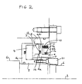
- Fig. 1 is a partial longitudinal sectional view through the shaft seal showing the relevant structural elements of a non-contacting shaft seal of the type described above. The shaft seal is incorporated in a turbo-machine (not shown), such as a compressor in this example. There is shown a
shaft seal 1 having a (non-rotating) sealing element orring 2 mounted coaxially with the shaft axis (denoted by reference numeral 3), and a rotary sealing part orring 4 located coaxially with thesealing ring 2, and therefore also with theshaft axis 3. It will be appreciated that the vertical sectional view of Figure 1, for simplicity, shows only the portion of the shaft seal located above the shaft axis. The sealingring 4 is mounted on aninner sleeve 5 having aradial flange 5a against which the sealingring 4 abuts, thesleeve 5 being mounted on theshaft 6 such that theshaft 6,inner sleeve 5 androtary sealing ring 4 co-rotate as a single rotary element. In addition, a locatingsleeve 7 is bolted toinner sleeve 5. Theassembly comprising components ring 21 and in the opposite axial direction by the high pressure acting inside the compressor. - The shaft seal also has a
seal housing 8 and apusher sleeve 9 disposed between a radiallyinward flange 8b of theseal housing 8 and sealingring 2. The pusher sleeve has a radial flange 9b against which a plurality of biasing springs (one of which, 10, is shown in Figure 1,) located at the same axial position in respectiveblind holes 11 in radiallyinward flange 8b and distributed about the shaft axis, act to urge thepusher sleeve 9 against the sealingring 2. The (non-rotary)sealing ring 2 androtary sealing ring 4 together form a contactless primary seal when the turbo-machine (or pressurized machine) is in operation, which substantially prevents fluid flow between the sealing faces of the primary seal, from the high pressure radially outer side to the low pressure radially inner side. The sealing face of sealingring 2 has shallow grooves cut into its front surface to generate the required separation between the sealing faces ofsealing rings rotary sealing ring 4. - Preferred designs for the grooves are given in more detail in Publish International Application WO-A-96/15397 of Dresser-Rand Company and the preferred designs for the groove are incorporated herein by reference. The sealing
element 2 is normally made from carbon or other suitable material. - As shown in Figure 1, the
sealing element 2 is afforded limited axial movement against the biasing force of thesprings 10. These springs provide a relatively small net biasing force so that when the shaft is rotating at normal speed, the generated separating forces cause thesealing ring 4 to separate from the sealingring 2. The gap between these rings adjusts itself such that the generated opening forces on the one hand and the sum of the generated closing forces and the spring biasing force on the other hand are equal to one another. However, when the shaft is at rest the springs act to move the sealingring 2 into contact with therotary sealing ring 4. - A high-pressure gas is supplied to the radially outer edge of the
seal rings - The high pressure at the high-pressure radial side acts around the rear face of sealing
element 2 down to a so-called equilibrium balance diameter.Secondary seals element 2 to the low-pressure radial side (atmospheric pressure). The balance diameter is determined essentially by the contact line ofsecondary seal 12 with thehousing 8. - The first
secondary seal 12 is provided between thepusher sleeve 9 and the radiallyinward flange 8b of theseal housing 8. This seal can be of any suitable form, such as a conventional O-ring, or, as shown, a spring-energised U-seal. Other forms of seal are possible and the precise form selected is not material. The firstsecondary seal 12, as shown in Figures 1, la, is located in achannel 14 formed in the main axially-extending sleeve portion 9a of thepusher sleeve 9. This secondary seal presses sealingly against the bottom of thechannel 14 formed in the main axially-extending sleeve portion 9a. It also presses sealingly against the axially-extending inner radial face of the radiallyinward flange 8b, thereby defining the equilibrium balance diameter for the shaft seal when operating in its equilibrium mode. - The further
secondary seal 13 is provided between the rear face of sealingring 2 and the radial flange 9b ofpusher sleeve 9. Again, this secondary seal can take the form of an O-ring or, as shown, a spring-energised U-seal or Y-seal. Thesecondary seal 13 is located in achannel 15 formed inpusher sleeve 9. Alternatively, thechannel 15 could be formed in sealingelement 2. - In use of the
shaft seal 1, the high-pressure working fluid of the compressor is admitted to the high-pressure radial side of the primary seal. This pressure acts on an outer annular region of the front face of the radial flange 9a ofpusher sleeve 9, the outer annular region having an inner diameter defined by the line of sealing of thesecondary seal 13 against the sealingring 2 and the radially outer diameter of radial flange 9a. The high-pressure fluid also acts against the rear face ofpusher sleeve 9 and down to the balance diameter. The secondary seals 12, 13 seal the applied high-pressure from the low-pressure radial side, which is at atmospheric pressure where a single shaft seal is used or, if multiple shaft seals are provided in cascade, at a lower pressure than the pressure to be sealed. Because of the pressure differential acting on the area of the rear face of radial flange 9a from the sealing diameter of theseal 13 down to the balance diameter, there is a net closing force (to the left in Figure 1) acting on thepusher sleeve 9, against the sealingring 2 at all times. This closing force is supplemented by the action of the biasing springs 10, and these closing forces are applied in the closing direction against sealingring 2. In addition, the high pressure fluid acting on the front faces of sealingring 2 produces an opening force, while the high pressure fluid acting on the rear faces down to the sealing diameter ofsecondary seal 13 produces a closing force. Still further, the taper-shaped surface recesses or grooves cut in the front face of sealing ring 2 (or rear face of sealing ring 4) generate separating pressure fields acting between the sealing rings 2, 4, the magnitude of the pressure fields depending on the rotational speed of the compressor shaft. The high pressure to be sealed, the depths of the recesses or grooves and the size of the gap between the sealing rings 2, 4 also influence the magnitude of the pressure fields. Whether the sealing rings 2, 4 of the shaft seal are in contact or separated depends on the magnitudes of the generated opening and closing forces, and the net spring biasing force. - When the compressor is started up, as the rotational speed of the
shaft 6 initially starts to build up, the primary seal maintains a substantially fluid-tight seal between the high-pressure and low-pressure radial sides, by virtue of sealing contact between the sealing rings 2, 4. Under these conditions, the net separating force generated by the primary seal is insufficient to overcome the sum of the spring biasing forces and the net closing force acting on the primary seal due to the applied high-pressure. - However, when the compressor shaft speed reaches a sufficient value such that the applied fluid pressure is adequate to generate a separating force that overcomes the net closing force acting on the
sealing ring 2, this sealing ring will start to move away from the sealingring 4 into an equilibrium position in which it maintains a contactless seal between therotating sealing ring 2 and thenon-rotating sealing ring 4. As described above, thesecondary seals ring 2 and thepusher sleeve 9. - An example of a shaft seal as described above is disclosed in WO-A-96/33358, belonging to the present Applicant's affiliated Company Dresser-Rand Company.
- According to a known modification shown in Figure 2, the
channel 14, instead of being formed in thepusher sleeve 9, is formed in theseal housing 8. Such arrangements (but only as such) are disclosed in EP-A-0591586 of Nippon Pillar Packing Co. Ltd. and US-A-5421593 belonging to the same proprietor. - Shaft seals of the type described above with reference to Figures 1 and 2 operate satisfactorily at typical sealing pressures of compressors that have been manufactured in the past. Typically, such compressors have been manufactured for compressing gases at pressures of typically from about 200 bar to about 500 bar. However, the industry is now demanding compressors to compress gas from 300 bar or more to 800 bar or more. On the other hand, it has been found that existing shaft seal designs are not adequate to withstand such inlet-pressure values, for the reasons now to be described with reference to Figures 1a and 2a.
- These Figures show, in deliberately exaggerated manner for the purposes of illustration, the effect of operating under such high-pressure values. As shown in these Figures, the high-pressure acting on the outer face of the axially-extending main sleeve portion 9a of the
pusher sleeve 9 between theseal 12 and the junction with the rear face of the radial portion 9b deforms the main axially-extending portion inwardly with a deflection increasing with increasing axial distance in the axial direction away from the junction between the main axially-extending portion and the radial flange 9a. This torsional deformation is indicated by letter A in Figure la. Correspondingly, the high pressure acting against the inside (front) face of radiallyinner flange 8b torsionally deforms that flange rearwardly, as indicated by arrow B. The consequence is that, as shown in Figures 1a, 2a, the very small gap normally existing between the inner face of the radiallyinward flange 8b of theseal housing 8 and the outer face of the main axially-extending sleeve portion 9a of thepusher sleeve 9 is enlarged. With increasing high-pressure acting against thesecondary seal 12 and widening the gap between theflange 8b and main sleeve portion of thepusher sleeve 9, a bead 12b starts to form as thesecondary seal 12 starts to be extruded through the widening gap. When there is no such bead on thesecondary seal 12, this seal offers little frictional resistance to the rearward axial sliding of thepusher sleeve 9. However, when the bead 12b starts to form, the frictional resistance increases, potentially significantly and even to the point where the pusher sleeve can become united with thehousing 8. Furthermore, as the bead 12b continues to grow, an increasingly unstable situation can develop whereby the sealing ability of thesecondary seal 12 is progressively lessened due to the continuing extrusion, until eventually an unstable situation is reached in which theseal 12 is expelled or blown out through the gap, resulting in failure of the shaft seal. It is noted that the bead 12b does not normally form around the entire rear circumferential region of thesecondary seal 12 but generally only at a single angular position about the seal circumference. - One possible solution to this problem that has been considered is to minimise the gap existing between the
radial flange 8b and thepusher sleeve 9 when the shaft seal is not in use, but there is a limit to how much this gap can be. reduced because thepusher sleeve 9 must be free to undergo limited axial movement when the shaft seal is not in operation. Furthermore, radially inward deflection of the main sleeve portion of thepusher sleeve 9 is inevitable, yet this sleeve must not be allowed to come into contact with the (rotating) shaftinner sleeve 5 under full operating pressure. - Another potential solution which has been considered is to use harder materials for forming the sealing parts of the
secondary seal 12, or to use back-up rings of harder material than the sealing parts themselves of the secondary seal. However, there is a limit to how hard the selected materials can be, particularly since harder materials are less effective to provide the required sealing effect and they also increase the friction forces generated. - Spring energised polymer seals have been proposed. However, the operating pressure at which beads start to form on such seals is about 200-250 bar.
- The present invention seeks to provide a shaft seal which is improved in the above respects and can withstand high operating pressures, in the range from zero bar to 300 bar or more. It relates to a shaft seal as initially defined and is characterised by an auxiliary sleeve disposed around the pusher sleeve coaxially therewith and maintained in sealing contact with the pusher sleeve by the first sealing member, the auxiliary sleeve being arranged to be urged in an axial direction by fluid pressure acting at the high pressure radial side to form a tertiary seal.
- Because the fluid high-pressure acting on the auxiliary sleeve produces a net radially inwards force, it can be arranged that the small gap existing between the pusher and auxiliary sleeves when no fluid pressure is applied to the shaft seal will not enlarge to the extent that occurs in the prior art shaft seals disclosed with reference to Figures 1, 1a and 2, 2a. Therefore, there is a reduced tendency for appreciable frictional resistance to develop between the first sealing member and the seal housing, or for the first sealing member to be expelled under high-pressure operation.
- The function of the tertiary seal is merely to maintain sealing contact between the seal housing and auxiliary sleeve. Ideally, the geometry, material and design of the auxiliary sleeve is such that the distortion of the auxiliary sleeve substantially matches that of the pusher sleeve under fluid pressure, so that the gap between these two elements remains substantially the same irrespective of the fluid pressure acting, thereby avoiding or minimising the risk of a bead forming on the first sealing member.
- Preferably, said channel in which said first sealing member is located is formed in the pusher sleeve. This maximises the closing force acting on the pusher sleeve when operating under high fluid pressure, because then the seal provided by the first sealing member against the pusher sleeve is located at a radially inward location. Alternatively, said channel in which said first sealing member is located may be formed in the auxiliary sleeve.
- Preferably, the biasing means acts between the pusher sleeve and the auxiliary sleeve. This arrangement guarantees that the sealing effect of the tertiary seal is kept integral at all times, so that when the fluid pressure is applied it is prevented from passing unrestrictedly past the auxiliary sleeve to the low-pressure radial side. However, it is alternatively possible for the biasing means to act between the seal housing and the pusher sleeve, because it is considered that when the high fluid pressure is applied at the high-pressure radial side, the auxiliary sleeve will, as a result of the location of the tertiary seal, be urged in the axial direction, ensuring that the tertiary seal performs its required sealing function. In its simplest form, the tertiary seal is provided by face-to-face contact between transverse faces of the auxiliary sleeve and seal housing, when the shaft seal is in use. However, it is preferred that a separate tertiary seal is provided, for greater sealing integrity.
- Suitably, the tertiary seal comprises an O-ring located in a channel formed in the transverse end face of the auxiliary sleeve. In accordance with a modification, the tertiary seal comprises an O-ring located in a channel formed in the transverse end face of the seal housing. Alternatively, it can comprise a spring-energised U-seal or Y-seal.
- Normally, the pusher sleeve will comprise a main axially-extending portion with a radial flange at one end in contact face-to-face with the sealing element. This design for the pusher sleeve is preferred because then the main axially-extending portion can serve to provide for accommodating the required limited axial movement of the pusher sleeve while the first sealing member maintains sealing contact with the auxiliary sleeve, and the radial flange conveniently serves to receive the bias force of the biasing means and apply it against the sealing element. Furthermore, the flange substantially resists radially inward distortion of the pusher sleeve at the one axial end of the pusher sleeve. When the pusher sleeve has this preferred form, the auxiliary sleeve preferably similarly comprises a main axially-extending portion with a radial flange at one end facing the flange of the pusher sleeve. This arrangement for the auxiliary sleeve helps to ensure that its distortion under pressure closely conforms with that of the pusher sleeve.
- In another arrangement, the pusher sleeve is of the same construction, but the auxiliary sleeve is in the form of a sleeve over its entire length. Then, when the shaft seal is in use, the high fluid pressure acting on the outside of the low-pressure axial end portion of the auxiliary seal beyond the sealing location of the first sealing member will deflect that end portion inwardly, again reducing the likelihood of the first sealing member being blown out of the shaft seal.
- The shaft seal may be incorporated in a turbo-machine or other pressurized machine, though for convenience the description which follows relates to the specific case of a compressor, as in the prior art examples described with reference to Figures 1, 1a and 2, 2a.
- For a better understanding of the invention and to show how the same may be carried into effect, reference will now be made, by way of example, to the accompanying drawings in which:-
- Figure 1 is a partial longitudinal sectional view through a first known shaft seal showing the relevant structural elements of the seal;
- Figure 1a is an enlarged view of part of the seal, showing the distortion of certain structural elements in an exaggerated manner for illustrative purposes;
- Figures 2, 2a are corresponding views to Figures 1, 1a for a modified known arrangement;
- Figures 3, 3a are corresponding views to Figures 1, 1a, respectively, of a first embodiment of the invention;
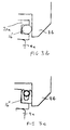
- Figures 3b, 3c respectively show, on an enlarged scale, alternative forms of tertiary seal to that incorporated in the embodiment according to Figures 3, 3a;
- Figure 4 is an exploded view of the shaft seal according to the first embodiment; and
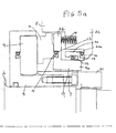
- Figures 5, 5a are corresponding views to Figures 3, 3a, respectively, of a second embodiment of the invention.
-
- The shaft seal illustrated in Figures 3 and 4 is identical to that described above with reference to Figure 1, except in the respects described below. To the extent that the construction is the same, this is indicated by the use of identical reference numerals.
- The
shaft seal 1 additionally comprises anauxiliary sleeve 20 disposed around thepusher sleeve 9 co-axially therewith, with a small gap radially separating the twosleeves recess 17 within the radiallyinner flange 8b. The auxiliary sleeve comprises a main axially-extendingsleeve portion 20a having at one end a radial flange 20b facing the rear face of the radial flange 9a of thepusher sleeve 9. The biasing springs 10 act between the flanges of 9b, 20b of thepusher sleeve 9 andauxiliary sleeve 20, thereby urging the auxiliary sleeve further into therecess 17 in theseal housing 8. Atertiary seal 16 provides a substantially fluid-type seal between the transverse rear-facing end face of thesleeve portion 20a and an adjacent forwardly-facing, transverseannular face 19 of the seal housing. As shown, this seal is preferably in the form of a spring energised Y-seal. Alternatively, it can be an O-ring 16' located in a channel formed in thesleeve portion 20a (see Figure 3b) or in the radiallyinward flange 8b of the seal housing, or a spring energised U-seal 16" (see Figure 3c) or a spring-energised Y-seal. The first secondary sealingmember 12 provides a substantially fluid-tight seal between the auxiliary sleeve and thepusher sleeve 9. - Figure 4 is an exploded view of the shaft seal, giving a clear indication of the geometry of the respective elements of the shaft seal. This Figure also shows the modification in which the taper shaped grooves are formed in the sealing face of
rotary sealing ring 4, rather than of thenon-rotating sealing ring 2. - In use of the shaft seal, the high pressure fluid acting at the high-pressure fluid side of the primary seal acts, just as in the case of the known shaft seals according to Figures 1, 1a and 2, 2a, against the
pusher sleeve 9 to cause the axially-extending sleeve portion to deflect radially inwardly. The distortion of the axially extending sleeve portion is progressive from the axial location ofsecondary seal 12 along the length of the pusher sleeve, because of the pressure differential between the inside and outside pressures acting onmain sleeve portion 20a. The flange 9a substantially resists distortion of the pusher sleeve in the region of that end. The maximum inward radial distortion occurs at the other end. - However, in the present embodiment, as shown in Figure 3b, the high fluid pressure acting on the auxiliary sleeve, in particular around its external surface, similarly distorts the
auxiliary sleeve 20. Therefore, the small gap existing between the outer surface of thepusher sleeve 9 and the inner surface of theauxiliary sleeve 20 does not change much, thereby avoiding or at least minimising the possibility of the high-pressure acting on thesecondary seal 12 from causing the seal to be extruded into the gap. Therefore, even when operating under higher pressures e.g. upwards of 300 bar, thesecondary seal 12 will not start to offer high frictional resistance to the sliding action of the pusher sleeve, nor be expelled or blown out of thechannel 14 in thepusher sleeve 9. - It is preferred to design the
auxiliary sleeve 20 such that the gap between it and thepusher sleeve 9 remains substantially constant irrespective of the pressure which is acting at the high pressure radial side. This result can be achieved by appropriate choice of the geometry and relative dimensions of theauxiliary sleeve 20 andpusher sleeve 9, and by suitable choice of the materials from which these two components are made. Preferably, the radial and toroidal stiffnesses of theauxiliary sleeve 20 are the same as those of thepusher sleeve 9. It is also preferred that the materials from which theauxiliary sleeve 20 andpusher sleeve 9 are made are the same, so that the gap between those two components remains substantially invariant, irrespective of temperature changes. - The embodiment according to Figure 5 shows two possible modifications which may be adopted singly or in combination.
- The first modification, merely involves accommodating the secondary sealing
member 12 in achannel 14 formed in theauxiliary sleeve 20, rather than in thepusher sleeve 9. - The second modification is that the
springs 10 do not act at one end against theauxiliary sleeve 20, but merely function to urge thepusher sleeve 9 against the sealingring 2. Nevertheless, it is still considered with this arrangement that adequate sealing performance is provided by thetertiary seal 16, because, when the high pressure fluid is acting at the high-pressure radial side, it will produce a net axial force acting to urge theauxiliary sleeve 20 against the radiallyinward flange 8b of theseal housing 8, due to the locations of thesecondary seal 12 and thetertiary seal 16 on the auxiliary sleeve. - It is pointed out that in the embodiment according to Figure 5, the
auxiliary sleeve 20 does not have any end flange as in the Figures 3 and 4 embodiment, but is in the form of a sleeve over its entire axial extent. Because of the sealing function of thesecondary seal 12, the internal and external forces acting on the axial portion of the auxiliary sleeve at the high pressure axial side of thesecondary seal 12 balance each other, whereas there is a net inward radial force acting on the portion of the auxiliary sleeve at the low-pressure axial side of thesecondary seal 12, which distorts the auxiliary seal inwardly towards the axially extending sleeve portion ofpusher sleeve 9. This distortion produces the effect of minimising the gap between the pusher and auxiliary sleeves on the low-pressure fluid side ofseal 12, thereby minimising the likelihood of theseal 12 being expelled. - As an alternative to the biasing
spring 10, a wave spring for example in the form of a single annulus of suitable sheet material, e.g. metal, (or several stacked together) may be deformed so as to form successive undulations at different angular positions about the axis of the annulus. The deformed annulus is compressed between theprimary sealing ring 2 and theauxiliary sleeve 20 or radiallyinward flange 8b (as the case may be), thereby providing the required biasing action in the manner of a leaf spring. - In the described embodiments, the source of the high-pressure fluid is the working fluid of the compressor, whose pressure accordingly increases with increasing compressor operating speed. Where a separate source of high-pressure fluid from the working fluid is used, its pressure will normally be held at a given delivery pressure. When the compressor is at rest, the net force acting on the primary seal is preferably a closing force, maintaining the sealing
ring 2 against the sealingring 4. However, when the compressor has speeded up sufficiently, the separating force generated by the tapered grooves or recesses in the one sealing ring or the other of the primary seal is sufficient to separate the two rings. Therefore, the operation is essentially the same as in the case where the working fluid of the compressor is the source of the high-pressure fluid. Although it is preferred in this embodiment that the sealingring 2 is held against the sealingring 4 when the compressor is at rest, it is possible for the shaft seal to be slightly open under rest conditions, since the essential requirement is merely that the shaft seal provides contactless operation when the compressor is operating at normal operational speed.
Claims (13)
- A shaft seal comprising a sealing element (2), a rotary sealing part (4) mounted coaxially with the sealing element and forming therewith a contactless primary seal between opposed faces of the sealing element (2) and rotary sealing part (4) to substantially prevent fluid flow across the primary seal from a high pressure radial side to a low-pressure radial side, a seal housing (8), a pusher sleeve (9) disposed, between the seal housing and the sealing element, coaxially with and in contact with the sealing element (2), biasing means (10) urging the pusher sleeve (9) away from the seal housing (8) and against the sealing element (2) to urge the sealing element axially towards the rotary sealing part (4), and a first sealing member (12) disposed about the pusher sleeve (9) and located, in a channel (14), in communication with the high-pressure radial side to provide a secondary seal for the pusher sleeve (9) between the high-pressure and low-pressure radial sides, characterised by an auxiliary sleeve (20) disposed around the pusher sleeve (9) coaxially therewith and maintained in sealing contact with the pusher sleeve (9) by the first sealing member (12), the auxiliary sleeve being arranged to be urged in an axial direction by fluid pressure acting at the high-pressure radial side to form a tertiary seal (16) between the auxiliary sleeve (20) and seal housing (8).
- A shaft seal according to claim 1, wherein said channel (14) in which said first sealing member (12) is located is formed in the pusher sleeve (9).
- A shaft seal according to claim 1, wherein said channel (14) in which said first sealing member (12) is located is formed in the auxiliary sleeve (20).
- A shaft seal according to any preceding claim, wherein the biasing means (10) acts between the pusher sleeve (9) and the auxiliary sleeve (20).
- A shaft seal according to any one of claims 1 to 3, wherein the biasing means (10) acts between the seal housing (8) and the pusher sleeve (9).
- A shaft seal according to any preceding claim, wherein the tertiary seal (16) is provided by face-to-face contact between transverse faces of the auxiliary sleeve and seal housing, when the shaft seal is in use.
- A shaft seal according to any one of claims 1 to 5, wherein the tertiary seal (16) comprises an O-ring (17) located in a channel (18) formed in the transverse end face of the auxiliary sleeve (9).
- A shaft seal according to any one of claims 1 to 5, wherein the tertiary seal (16) comprises an O-ring (17) located in a channel (18) formed in the transverse end face of the seal housing (8).
- A shaft seal according to any one of claims 1 to 5, wherein the tertiary seal (16) comprises a spring-energised U-seal.
- A shaft seal according to any one of claims, 1 to 5, wherein the tertiary seal (16) is a spring-energised Y-seal.
- A shaft seal according to any preceding claim, wherein the pusher sleeve (9) comprises a main axially extending portion (9a) with a radial flange (9b) at one end in face-to-face contact with the sealing element (2) and the auxiliary sleeve (20) also comprises a main axially extending portion with a radial flange (20b) at one end facing the flange (9a) of the pusher sleeve (9).
- A shaft seal according to any one of claims 1 to 10, wherein the pusher sleeve (9) comprises a main axially extending portion (9a) with a radial flange (9b) at one end in face-to-face contact with the sealing element (2) and the auxiliary sleeve (20) is in the form of a sleeve over its entire length.
- A turbo-machine or other pressurized machine incorporating a shaft seal according to any preceding claim.
Priority Applications (9)
| Application Number | Priority Date | Filing Date | Title |
|---|---|---|---|
| EP99400460A EP1031775A1 (en) | 1999-02-25 | 1999-02-25 | Shaft seal |
| AU35530/00A AU3553000A (en) | 1999-02-25 | 2000-02-25 | Shaft seal |
| EP00914089A EP1153233B1 (en) | 1999-02-25 | 2000-02-25 | Shaft seal |
| DE60007513T DE60007513T2 (en) | 1999-02-25 | 2000-02-25 | SHAFT SEAL |
| PCT/EP2000/001579 WO2000050789A1 (en) | 1999-02-25 | 2000-02-25 | Shaft seal |
| JP2000601348A JP4684420B2 (en) | 1999-02-25 | 2000-02-25 | Shaft seal |
| CA002362182A CA2362182A1 (en) | 1999-02-25 | 2000-02-25 | Shaft seal |
| US09/938,175 US6601854B2 (en) | 1999-02-25 | 2001-08-23 | Shaft seal |
| US10/345,569 US6916022B2 (en) | 1999-02-25 | 2003-01-16 | Shaft seal |
Applications Claiming Priority (1)
| Application Number | Priority Date | Filing Date | Title |
|---|---|---|---|
| EP99400460A EP1031775A1 (en) | 1999-02-25 | 1999-02-25 | Shaft seal |
Publications (1)
| Publication Number | Publication Date |
|---|---|
| EP1031775A1 true EP1031775A1 (en) | 2000-08-30 |
Family
ID=8241890
Family Applications (2)
| Application Number | Title | Priority Date | Filing Date |
|---|---|---|---|
| EP99400460A Withdrawn EP1031775A1 (en) | 1999-02-25 | 1999-02-25 | Shaft seal |
| EP00914089A Expired - Lifetime EP1153233B1 (en) | 1999-02-25 | 2000-02-25 | Shaft seal |
Family Applications After (1)
| Application Number | Title | Priority Date | Filing Date |
|---|---|---|---|
| EP00914089A Expired - Lifetime EP1153233B1 (en) | 1999-02-25 | 2000-02-25 | Shaft seal |
Country Status (7)
| Country | Link |
|---|---|
| US (2) | US6601854B2 (en) |
| EP (2) | EP1031775A1 (en) |
| JP (1) | JP4684420B2 (en) |
| AU (1) | AU3553000A (en) |
| CA (1) | CA2362182A1 (en) |
| DE (1) | DE60007513T2 (en) |
| WO (1) | WO2000050789A1 (en) |
Cited By (1)
| Publication number | Priority date | Publication date | Assignee | Title |
|---|---|---|---|---|
| WO2007107690A1 (en) * | 2006-03-18 | 2007-09-27 | John Crane Uk Limited | High pressure gas seals |
Families Citing this family (23)
| Publication number | Priority date | Publication date | Assignee | Title |
|---|---|---|---|---|
| JP3933469B2 (en) * | 2001-12-28 | 2007-06-20 | イーグル工業株式会社 | Mechanical seal device |
| GB0317055D0 (en) * | 2003-07-22 | 2003-08-27 | Cross Mfg Co 1938 Ltd | Improvements relating to aspirating face seals and thrust bearings |
| US20050242515A1 (en) * | 2004-04-28 | 2005-11-03 | Brooks Melvin D | Dry gas seal and method for making the same |
| ZA200507096B (en) * | 2004-09-07 | 2006-06-28 | Crane John Inc | Sealing system for slurry pump |
| US20060188381A1 (en) * | 2005-02-24 | 2006-08-24 | Honeywell International, Inc. | Seal assembly for hydraulic pump output shaft |
| DE202005011137U1 (en) * | 2005-07-14 | 2005-09-29 | Burgmann Industries Gmbh & Co. Kg | Rotating mechanical seal arrangement has each slide ring on side facing away from sealing face axially supported on support component via annular contact face between support component and adjacent end face of slide ring |
| GB0806253D0 (en) * | 2008-04-07 | 2008-05-14 | Cross Mfg 1938 Company Ltd | Non-contacting face seals and thrust bearings |
| US20090252595A1 (en) * | 2008-04-07 | 2009-10-08 | Cross Manufacturing Co. )1983) Ltd. | Non-contacting face seals and thrust bearings |
| PL2409056T3 (en) * | 2009-03-16 | 2016-03-31 | Vulco Sa | Mechanical seal |
| AU2013204370B2 (en) * | 2009-03-16 | 2016-11-17 | Vulco S.A. | Mechanical seal |
| US20100253005A1 (en) * | 2009-04-03 | 2010-10-07 | Liarakos Nicholas P | Seal for oil-free rotary displacement compressor |
| DE102010024291B4 (en) * | 2010-04-23 | 2013-04-18 | Carl Freudenberg Kg | Mechanical seal with rotating counter ring with precisely defined clamping |
| GB201013844D0 (en) * | 2010-08-19 | 2010-09-29 | Rolls Royce Plc | Intershaft seal |
| US8814547B2 (en) * | 2011-02-25 | 2014-08-26 | Hamilton Sundstrand Corporation | Seal retaining sleeve for gear pump |
| JP5712067B2 (en) * | 2011-06-27 | 2015-05-07 | 株式会社日立製作所 | High temperature fluid shaft seal device |
| US9190312B2 (en) | 2011-07-27 | 2015-11-17 | Advanced Ion Beam Technology, Inc. | Extremely low temperature rotary union |
| KR102002562B1 (en) | 2012-11-28 | 2019-07-22 | 한화파워시스템 주식회사 | Gas seal assembly |
| CN107076308B (en) | 2014-11-04 | 2019-12-06 | 伊格尔工业股份有限公司 | Mechanical sealing device |
| CN107076307B (en) * | 2014-11-04 | 2019-06-21 | 伊格尔工业股份有限公司 | Mechanically-sealing apparatus |
| US10234036B2 (en) | 2015-01-12 | 2019-03-19 | Rolls-Royce Corporation | Wide differential pressure range air riding carbon seal |
| CA3011057A1 (en) * | 2016-01-13 | 2017-07-20 | Ball Corporation | System and method for orienting the rolling direction of an end shell in a metal container manufacturing process |
| KR101695255B1 (en) * | 2016-03-07 | 2017-01-12 | 한화테크윈 주식회사 | Gas seal assembly |
| JP6853817B2 (en) * | 2016-04-27 | 2021-03-31 | イーグル工業株式会社 | mechanical seal |
Citations (8)
| Publication number | Priority date | Publication date | Assignee | Title |
|---|---|---|---|---|
| US4095806A (en) * | 1977-07-05 | 1978-06-20 | The Babcock & Wilcox Company | Seal arrangement |
| DE3942408A1 (en) * | 1989-11-06 | 1991-05-08 | Escher Wyss Ag | Shaft dry gas seal - has flexible sealing ring between seal body and socket on shaft |
| EP0591586A1 (en) | 1992-09-03 | 1994-04-13 | Nippon Pillar Packing Co., Ltd. | Seal for a rotating member |
| US5421593A (en) | 1993-08-05 | 1995-06-06 | Nippon Pillar Packing Co., Ltd. | Shaft seal device |
| WO1996015397A1 (en) | 1994-11-16 | 1996-05-23 | Dresser-Rand Company | A shaft seal |
| US5558342A (en) * | 1994-08-05 | 1996-09-24 | Durametallic Corporation | Mechanical seal with spring drive |
| WO1996033358A1 (en) | 1995-04-20 | 1996-10-24 | Dresser-Rand Company | A shaft seal |
| WO1996033357A1 (en) | 1995-04-20 | 1996-10-24 | Dresser-Rand Company | A shaft seal |
Family Cites Families (21)
| Publication number | Priority date | Publication date | Assignee | Title |
|---|---|---|---|---|
| US3515394A (en) * | 1964-06-05 | 1970-06-02 | Sealol | Vibration damping means for resilient convoluted members |
| US3580587A (en) * | 1967-07-22 | 1971-05-25 | Klein Schanzlin & Becker Ag | Contact-free hydrostatic seal |
| US3475033A (en) * | 1967-12-01 | 1969-10-28 | Continental Illinois National | Liquid sensing seal for rotating shaft |
| JPS5712305Y2 (en) * | 1976-07-23 | 1982-03-11 | ||
| US4212475A (en) * | 1979-01-15 | 1980-07-15 | Crane Packing Co. | Self aligning spiral groove face seal |
| US4191386A (en) * | 1978-01-16 | 1980-03-04 | Durametallic Corporation | Self-cooled mechanical seal |
| JPS6051360A (en) * | 1983-08-31 | 1985-03-22 | Canon Inc | Image forming device |
| US5244215A (en) * | 1985-05-10 | 1993-09-14 | Chicago Rawhide Manufacturing Company | Rotary shaft seal with retractable excluder lip |
| US4872517A (en) * | 1988-02-08 | 1989-10-10 | Shaw Daniel G | Rotatable fluid conductor for well apparatus |
| JP2648816B2 (en) * | 1988-05-10 | 1997-09-03 | イーグル工業株式会社 | Cylindrical face seal |
| US5224714A (en) * | 1990-07-18 | 1993-07-06 | Ebara Corporation | Noncontacting face seal |
| US5503407A (en) * | 1994-04-18 | 1996-04-02 | Stein Seal Company | Windbacks for rotating shafts |
| JP2790063B2 (en) * | 1994-11-29 | 1998-08-27 | 日本ジョン・クレーン株式会社 | mechanical seal |
| US5954341A (en) * | 1996-07-30 | 1999-09-21 | John Crane Sealol Inc. | Bellows seal with drive collar for reverse pressure capability |
| US5938206A (en) * | 1996-11-01 | 1999-08-17 | John Crane Inc. | Pressure responsive primary ring for a non-contacting mechanical end face seal |
| US5681047A (en) * | 1996-11-01 | 1997-10-28 | John Crane Inc. | Pressure responsive primary ring geometry for a non-contacting mechanical end face seal |
| US5924697A (en) * | 1997-03-03 | 1999-07-20 | Durametallic Corporation | Double gas seal with bellows supported by backing and support rings |
| US6267382B1 (en) * | 1998-02-23 | 2001-07-31 | Dresser-Rand Company | Fail safe L-shaped spring carrier for gas seals |
| JP3650954B2 (en) * | 1998-09-18 | 2005-05-25 | イーグル工業株式会社 | Non-contact mechanical seal for high speed |
| US6182971B1 (en) * | 1998-12-09 | 2001-02-06 | Flowserve Management Company | Gas seal for pumps |
| US6293555B1 (en) * | 2000-02-01 | 2001-09-25 | Josef Sedy | Secondary seal for non-contacting face seals |
-
1999
- 1999-02-25 EP EP99400460A patent/EP1031775A1/en not_active Withdrawn
-
2000
- 2000-02-25 AU AU35530/00A patent/AU3553000A/en not_active Abandoned
- 2000-02-25 CA CA002362182A patent/CA2362182A1/en not_active Abandoned
- 2000-02-25 EP EP00914089A patent/EP1153233B1/en not_active Expired - Lifetime
- 2000-02-25 WO PCT/EP2000/001579 patent/WO2000050789A1/en active IP Right Grant
- 2000-02-25 JP JP2000601348A patent/JP4684420B2/en not_active Expired - Lifetime
- 2000-02-25 DE DE60007513T patent/DE60007513T2/en not_active Expired - Lifetime
-
2001
- 2001-08-23 US US09/938,175 patent/US6601854B2/en not_active Expired - Lifetime
-
2003
- 2003-01-16 US US10/345,569 patent/US6916022B2/en not_active Expired - Lifetime
Patent Citations (8)
| Publication number | Priority date | Publication date | Assignee | Title |
|---|---|---|---|---|
| US4095806A (en) * | 1977-07-05 | 1978-06-20 | The Babcock & Wilcox Company | Seal arrangement |
| DE3942408A1 (en) * | 1989-11-06 | 1991-05-08 | Escher Wyss Ag | Shaft dry gas seal - has flexible sealing ring between seal body and socket on shaft |
| EP0591586A1 (en) | 1992-09-03 | 1994-04-13 | Nippon Pillar Packing Co., Ltd. | Seal for a rotating member |
| US5421593A (en) | 1993-08-05 | 1995-06-06 | Nippon Pillar Packing Co., Ltd. | Shaft seal device |
| US5558342A (en) * | 1994-08-05 | 1996-09-24 | Durametallic Corporation | Mechanical seal with spring drive |
| WO1996015397A1 (en) | 1994-11-16 | 1996-05-23 | Dresser-Rand Company | A shaft seal |
| WO1996033358A1 (en) | 1995-04-20 | 1996-10-24 | Dresser-Rand Company | A shaft seal |
| WO1996033357A1 (en) | 1995-04-20 | 1996-10-24 | Dresser-Rand Company | A shaft seal |
Non-Patent Citations (2)
| Title |
|---|
| GABRIEL, RALPH P: "journal of american society of lubrication engineers", vol. 35, part 7 article "fundamentals of spiral groove non-contacting face seals", pages: 367 - 375 |
| SEDY, JOSEPH: "transaction of the american society of lubrication engineers", vol. 23, part 1 article "improved performance of film-riding gas seals through enhancement of hydrodynamic effect", pages: 35 - 44 |
Cited By (1)
| Publication number | Priority date | Publication date | Assignee | Title |
|---|---|---|---|---|
| WO2007107690A1 (en) * | 2006-03-18 | 2007-09-27 | John Crane Uk Limited | High pressure gas seals |
Also Published As
| Publication number | Publication date |
|---|---|
| DE60007513T2 (en) | 2004-11-11 |
| JP2002538384A (en) | 2002-11-12 |
| AU3553000A (en) | 2000-09-14 |
| US20020047239A1 (en) | 2002-04-25 |
| EP1153233B1 (en) | 2004-01-02 |
| DE60007513D1 (en) | 2004-02-05 |
| JP4684420B2 (en) | 2011-05-18 |
| WO2000050789A1 (en) | 2000-08-31 |
| US20030107179A1 (en) | 2003-06-12 |
| EP1153233A1 (en) | 2001-11-14 |
| US6601854B2 (en) | 2003-08-05 |
| CA2362182A1 (en) | 2000-08-31 |
| US6916022B2 (en) | 2005-07-12 |
Similar Documents
| Publication | Publication Date | Title |
|---|---|---|
| EP1153233B1 (en) | Shaft seal | |
| EP1163463B1 (en) | Shaft seal | |
| EP0578377B1 (en) | Seals | |
| US7726660B2 (en) | Non-contacting seal for rotating surfaces | |
| US6347800B1 (en) | Fail safe L-shaped spring carrier for gas seals | |
| US5938206A (en) | Pressure responsive primary ring for a non-contacting mechanical end face seal | |
| US4659092A (en) | Mechanical seals | |
| EP2318738B1 (en) | Leaf seal | |
| US5681047A (en) | Pressure responsive primary ring geometry for a non-contacting mechanical end face seal | |
| US6267382B1 (en) | Fail safe L-shaped spring carrier for gas seals | |
| US6131913A (en) | Anti-rotation and axial locking arrangement of a gas seal on its sleeve | |
| US5192083A (en) | Single ring sector seal | |
| US11287043B2 (en) | High clearance seal assembly | |
| EP0404358A2 (en) | Mechanical face seals | |
| CN112334689B (en) | Mechanical seal with high pressure high temperature auxiliary seal |
Legal Events
| Date | Code | Title | Description |
|---|---|---|---|
| PUAI | Public reference made under article 153(3) epc to a published international application that has entered the european phase |
Free format text: ORIGINAL CODE: 0009012 |
|
| AK | Designated contracting states |
Kind code of ref document: A1 Designated state(s): AT BE CH CY DE DK ES FI FR GB GR IE IT LI LU MC NL PT SE |
|
| AX | Request for extension of the european patent |
Free format text: AL;LT;LV;MK;RO;SI |
|
| STAA | Information on the status of an ep patent application or granted ep patent |
Free format text: STATUS: THE APPLICATION HAS BEEN WITHDRAWN |
|
| 18W | Application withdrawn |
Withdrawal date: 20010306 |