EP3216992B1 - Mischer - Google Patents
Mischer Download PDFInfo
- Publication number
- EP3216992B1 EP3216992B1 EP17159284.3A EP17159284A EP3216992B1 EP 3216992 B1 EP3216992 B1 EP 3216992B1 EP 17159284 A EP17159284 A EP 17159284A EP 3216992 B1 EP3216992 B1 EP 3216992B1
- Authority
- EP
- European Patent Office
- Prior art keywords
- exhaust gas
- mixer
- duct
- area
- reactant
- Prior art date
- Legal status (The legal status is an assumption and is not a legal conclusion. Google has not performed a legal analysis and makes no representation as to the accuracy of the status listed.)
- Active
Links
Images


Classifications
-
- F—MECHANICAL ENGINEERING; LIGHTING; HEATING; WEAPONS; BLASTING
- F01—MACHINES OR ENGINES IN GENERAL; ENGINE PLANTS IN GENERAL; STEAM ENGINES
- F01N—GAS-FLOW SILENCERS OR EXHAUST APPARATUS FOR MACHINES OR ENGINES IN GENERAL; GAS-FLOW SILENCERS OR EXHAUST APPARATUS FOR INTERNAL-COMBUSTION ENGINES
- F01N3/00—Exhaust or silencing apparatus having means for purifying, rendering innocuous, or otherwise treating exhaust
- F01N3/08—Exhaust or silencing apparatus having means for purifying, rendering innocuous, or otherwise treating exhaust for rendering innocuous
- F01N3/10—Exhaust or silencing apparatus having means for purifying, rendering innocuous, or otherwise treating exhaust for rendering innocuous by thermal or catalytic conversion of noxious components of exhaust
- F01N3/24—Exhaust or silencing apparatus having means for purifying, rendering innocuous, or otherwise treating exhaust for rendering innocuous by thermal or catalytic conversion of noxious components of exhaust characterised by constructional aspects of converting apparatus
- F01N3/28—Construction of catalytic reactors
- F01N3/2892—Exhaust flow directors or the like, e.g. upstream of catalytic device
-
- F—MECHANICAL ENGINEERING; LIGHTING; HEATING; WEAPONS; BLASTING
- F01—MACHINES OR ENGINES IN GENERAL; ENGINE PLANTS IN GENERAL; STEAM ENGINES
- F01N—GAS-FLOW SILENCERS OR EXHAUST APPARATUS FOR MACHINES OR ENGINES IN GENERAL; GAS-FLOW SILENCERS OR EXHAUST APPARATUS FOR INTERNAL-COMBUSTION ENGINES
- F01N3/00—Exhaust or silencing apparatus having means for purifying, rendering innocuous, or otherwise treating exhaust
- F01N3/08—Exhaust or silencing apparatus having means for purifying, rendering innocuous, or otherwise treating exhaust for rendering innocuous
- F01N3/10—Exhaust or silencing apparatus having means for purifying, rendering innocuous, or otherwise treating exhaust for rendering innocuous by thermal or catalytic conversion of noxious components of exhaust
-
- B—PERFORMING OPERATIONS; TRANSPORTING
- B01—PHYSICAL OR CHEMICAL PROCESSES OR APPARATUS IN GENERAL
- B01F—MIXING, e.g. DISSOLVING, EMULSIFYING OR DISPERSING
- B01F23/00—Mixing according to the phases to be mixed, e.g. dispersing or emulsifying
- B01F23/20—Mixing gases with liquids
-
- B—PERFORMING OPERATIONS; TRANSPORTING
- B01—PHYSICAL OR CHEMICAL PROCESSES OR APPARATUS IN GENERAL
- B01F—MIXING, e.g. DISSOLVING, EMULSIFYING OR DISPERSING
- B01F23/00—Mixing according to the phases to be mixed, e.g. dispersing or emulsifying
- B01F23/20—Mixing gases with liquids
- B01F23/21—Mixing gases with liquids by introducing liquids into gaseous media
- B01F23/213—Mixing gases with liquids by introducing liquids into gaseous media by spraying or atomising of the liquids
- B01F23/2132—Mixing gases with liquids by introducing liquids into gaseous media by spraying or atomising of the liquids using nozzles
-
- B—PERFORMING OPERATIONS; TRANSPORTING
- B01—PHYSICAL OR CHEMICAL PROCESSES OR APPARATUS IN GENERAL
- B01F—MIXING, e.g. DISSOLVING, EMULSIFYING OR DISPERSING
- B01F25/00—Flow mixers; Mixers for falling materials, e.g. solid particles
- B01F25/20—Jet mixers, i.e. mixers using high-speed fluid streams
- B01F25/27—Mixing by jetting components into a conduit for agitating its contents
-
- B—PERFORMING OPERATIONS; TRANSPORTING
- B01—PHYSICAL OR CHEMICAL PROCESSES OR APPARATUS IN GENERAL
- B01F—MIXING, e.g. DISSOLVING, EMULSIFYING OR DISPERSING
- B01F25/00—Flow mixers; Mixers for falling materials, e.g. solid particles
- B01F25/30—Injector mixers
- B01F25/31—Injector mixers in conduits or tubes through which the main component flows
- B01F25/314—Injector mixers in conduits or tubes through which the main component flows wherein additional components are introduced at the circumference of the conduit
- B01F25/3141—Injector mixers in conduits or tubes through which the main component flows wherein additional components are introduced at the circumference of the conduit with additional mixing means other than injector mixers
-
- B—PERFORMING OPERATIONS; TRANSPORTING
- B01—PHYSICAL OR CHEMICAL PROCESSES OR APPARATUS IN GENERAL
- B01F—MIXING, e.g. DISSOLVING, EMULSIFYING OR DISPERSING
- B01F25/00—Flow mixers; Mixers for falling materials, e.g. solid particles
- B01F25/40—Static mixers
- B01F25/42—Static mixers in which the mixing is affected by moving the components jointly in changing directions, e.g. in tubes provided with baffles or obstructions
- B01F25/421—Static mixers in which the mixing is affected by moving the components jointly in changing directions, e.g. in tubes provided with baffles or obstructions by moving the components in a convoluted or labyrinthine path
- B01F25/423—Static mixers in which the mixing is affected by moving the components jointly in changing directions, e.g. in tubes provided with baffles or obstructions by moving the components in a convoluted or labyrinthine path by means of elements placed in the receptacle for moving or guiding the components
- B01F25/4231—Static mixers in which the mixing is affected by moving the components jointly in changing directions, e.g. in tubes provided with baffles or obstructions by moving the components in a convoluted or labyrinthine path by means of elements placed in the receptacle for moving or guiding the components using baffles
-
- B—PERFORMING OPERATIONS; TRANSPORTING
- B01—PHYSICAL OR CHEMICAL PROCESSES OR APPARATUS IN GENERAL
- B01F—MIXING, e.g. DISSOLVING, EMULSIFYING OR DISPERSING
- B01F25/00—Flow mixers; Mixers for falling materials, e.g. solid particles
- B01F25/40—Static mixers
- B01F25/45—Mixers in which the materials to be mixed are pressed together through orifices or interstitial spaces, e.g. between beads
- B01F25/452—Mixers in which the materials to be mixed are pressed together through orifices or interstitial spaces, e.g. between beads characterised by elements provided with orifices or interstitial spaces
- B01F25/4521—Mixers in which the materials to be mixed are pressed together through orifices or interstitial spaces, e.g. between beads characterised by elements provided with orifices or interstitial spaces the components being pressed through orifices in elements, e.g. flat plates or cylinders, which obstruct the whole diameter of the tube
-
- F—MECHANICAL ENGINEERING; LIGHTING; HEATING; WEAPONS; BLASTING
- F01—MACHINES OR ENGINES IN GENERAL; ENGINE PLANTS IN GENERAL; STEAM ENGINES
- F01N—GAS-FLOW SILENCERS OR EXHAUST APPARATUS FOR MACHINES OR ENGINES IN GENERAL; GAS-FLOW SILENCERS OR EXHAUST APPARATUS FOR INTERNAL-COMBUSTION ENGINES
- F01N13/00—Exhaust or silencing apparatus characterised by constructional features
- F01N13/18—Construction facilitating manufacture, assembly, or disassembly
- F01N13/1872—Construction facilitating manufacture, assembly, or disassembly the assembly using stamp-formed parts or otherwise deformed sheet-metal
-
- F—MECHANICAL ENGINEERING; LIGHTING; HEATING; WEAPONS; BLASTING
- F01—MACHINES OR ENGINES IN GENERAL; ENGINE PLANTS IN GENERAL; STEAM ENGINES
- F01N—GAS-FLOW SILENCERS OR EXHAUST APPARATUS FOR MACHINES OR ENGINES IN GENERAL; GAS-FLOW SILENCERS OR EXHAUST APPARATUS FOR INTERNAL-COMBUSTION ENGINES
- F01N3/00—Exhaust or silencing apparatus having means for purifying, rendering innocuous, or otherwise treating exhaust
- F01N3/02—Exhaust or silencing apparatus having means for purifying, rendering innocuous, or otherwise treating exhaust for cooling, or for removing solid constituents of, exhaust
- F01N3/021—Exhaust or silencing apparatus having means for purifying, rendering innocuous, or otherwise treating exhaust for cooling, or for removing solid constituents of, exhaust by means of filters
-
- F—MECHANICAL ENGINEERING; LIGHTING; HEATING; WEAPONS; BLASTING
- F01—MACHINES OR ENGINES IN GENERAL; ENGINE PLANTS IN GENERAL; STEAM ENGINES
- F01N—GAS-FLOW SILENCERS OR EXHAUST APPARATUS FOR MACHINES OR ENGINES IN GENERAL; GAS-FLOW SILENCERS OR EXHAUST APPARATUS FOR INTERNAL-COMBUSTION ENGINES
- F01N3/00—Exhaust or silencing apparatus having means for purifying, rendering innocuous, or otherwise treating exhaust
- F01N3/08—Exhaust or silencing apparatus having means for purifying, rendering innocuous, or otherwise treating exhaust for rendering innocuous
- F01N3/10—Exhaust or silencing apparatus having means for purifying, rendering innocuous, or otherwise treating exhaust for rendering innocuous by thermal or catalytic conversion of noxious components of exhaust
- F01N3/103—Oxidation catalysts for HC and CO only
-
- F—MECHANICAL ENGINEERING; LIGHTING; HEATING; WEAPONS; BLASTING
- F01—MACHINES OR ENGINES IN GENERAL; ENGINE PLANTS IN GENERAL; STEAM ENGINES
- F01N—GAS-FLOW SILENCERS OR EXHAUST APPARATUS FOR MACHINES OR ENGINES IN GENERAL; GAS-FLOW SILENCERS OR EXHAUST APPARATUS FOR INTERNAL-COMBUSTION ENGINES
- F01N3/00—Exhaust or silencing apparatus having means for purifying, rendering innocuous, or otherwise treating exhaust
- F01N3/08—Exhaust or silencing apparatus having means for purifying, rendering innocuous, or otherwise treating exhaust for rendering innocuous
- F01N3/10—Exhaust or silencing apparatus having means for purifying, rendering innocuous, or otherwise treating exhaust for rendering innocuous by thermal or catalytic conversion of noxious components of exhaust
- F01N3/18—Exhaust or silencing apparatus having means for purifying, rendering innocuous, or otherwise treating exhaust for rendering innocuous by thermal or catalytic conversion of noxious components of exhaust characterised by methods of operation; Control
- F01N3/20—Exhaust or silencing apparatus having means for purifying, rendering innocuous, or otherwise treating exhaust for rendering innocuous by thermal or catalytic conversion of noxious components of exhaust characterised by methods of operation; Control specially adapted for catalytic conversion
- F01N3/206—Adding periodically or continuously substances to exhaust gases for promoting purification, e.g. catalytic material in liquid form, NOx reducing agents
- F01N3/2066—Selective catalytic reduction [SCR]
-
- F—MECHANICAL ENGINEERING; LIGHTING; HEATING; WEAPONS; BLASTING
- F01—MACHINES OR ENGINES IN GENERAL; ENGINE PLANTS IN GENERAL; STEAM ENGINES
- F01N—GAS-FLOW SILENCERS OR EXHAUST APPARATUS FOR MACHINES OR ENGINES IN GENERAL; GAS-FLOW SILENCERS OR EXHAUST APPARATUS FOR INTERNAL-COMBUSTION ENGINES
- F01N3/00—Exhaust or silencing apparatus having means for purifying, rendering innocuous, or otherwise treating exhaust
- F01N3/08—Exhaust or silencing apparatus having means for purifying, rendering innocuous, or otherwise treating exhaust for rendering innocuous
- F01N3/10—Exhaust or silencing apparatus having means for purifying, rendering innocuous, or otherwise treating exhaust for rendering innocuous by thermal or catalytic conversion of noxious components of exhaust
- F01N3/24—Exhaust or silencing apparatus having means for purifying, rendering innocuous, or otherwise treating exhaust for rendering innocuous by thermal or catalytic conversion of noxious components of exhaust characterised by constructional aspects of converting apparatus
- F01N3/36—Arrangements for supply of additional fuel
-
- B—PERFORMING OPERATIONS; TRANSPORTING
- B01—PHYSICAL OR CHEMICAL PROCESSES OR APPARATUS IN GENERAL
- B01F—MIXING, e.g. DISSOLVING, EMULSIFYING OR DISPERSING
- B01F25/00—Flow mixers; Mixers for falling materials, e.g. solid particles
- B01F2025/93—Arrangements, nature or configuration of flow guiding elements
- B01F2025/931—Flow guiding elements surrounding feed openings, e.g. jet nozzles
-
- B—PERFORMING OPERATIONS; TRANSPORTING
- B01—PHYSICAL OR CHEMICAL PROCESSES OR APPARATUS IN GENERAL
- B01F—MIXING, e.g. DISSOLVING, EMULSIFYING OR DISPERSING
- B01F2101/00—Mixing characterised by the nature of the mixed materials or by the application field
- B01F2101/25—Mixing waste with other ingredients
-
- F—MECHANICAL ENGINEERING; LIGHTING; HEATING; WEAPONS; BLASTING
- F01—MACHINES OR ENGINES IN GENERAL; ENGINE PLANTS IN GENERAL; STEAM ENGINES
- F01N—GAS-FLOW SILENCERS OR EXHAUST APPARATUS FOR MACHINES OR ENGINES IN GENERAL; GAS-FLOW SILENCERS OR EXHAUST APPARATUS FOR INTERNAL-COMBUSTION ENGINES
- F01N13/00—Exhaust or silencing apparatus characterised by constructional features
- F01N13/009—Exhaust or silencing apparatus characterised by constructional features having two or more separate purifying devices arranged in series
-
- F—MECHANICAL ENGINEERING; LIGHTING; HEATING; WEAPONS; BLASTING
- F01—MACHINES OR ENGINES IN GENERAL; ENGINE PLANTS IN GENERAL; STEAM ENGINES
- F01N—GAS-FLOW SILENCERS OR EXHAUST APPARATUS FOR MACHINES OR ENGINES IN GENERAL; GAS-FLOW SILENCERS OR EXHAUST APPARATUS FOR INTERNAL-COMBUSTION ENGINES
- F01N2240/00—Combination or association of two or more different exhaust treating devices, or of at least one such device with an auxiliary device, not covered by indexing codes F01N2230/00 or F01N2250/00, one of the devices being
- F01N2240/20—Combination or association of two or more different exhaust treating devices, or of at least one such device with an auxiliary device, not covered by indexing codes F01N2230/00 or F01N2250/00, one of the devices being a flow director or deflector
-
- F—MECHANICAL ENGINEERING; LIGHTING; HEATING; WEAPONS; BLASTING
- F01—MACHINES OR ENGINES IN GENERAL; ENGINE PLANTS IN GENERAL; STEAM ENGINES
- F01N—GAS-FLOW SILENCERS OR EXHAUST APPARATUS FOR MACHINES OR ENGINES IN GENERAL; GAS-FLOW SILENCERS OR EXHAUST APPARATUS FOR INTERNAL-COMBUSTION ENGINES
- F01N2610/00—Adding substances to exhaust gases
- F01N2610/02—Adding substances to exhaust gases the substance being ammonia or urea
-
- F—MECHANICAL ENGINEERING; LIGHTING; HEATING; WEAPONS; BLASTING
- F01—MACHINES OR ENGINES IN GENERAL; ENGINE PLANTS IN GENERAL; STEAM ENGINES
- F01N—GAS-FLOW SILENCERS OR EXHAUST APPARATUS FOR MACHINES OR ENGINES IN GENERAL; GAS-FLOW SILENCERS OR EXHAUST APPARATUS FOR INTERNAL-COMBUSTION ENGINES
- F01N2610/00—Adding substances to exhaust gases
- F01N2610/14—Arrangements for the supply of substances, e.g. conduits
- F01N2610/1453—Sprayers or atomisers; Arrangement thereof in the exhaust apparatus
-
- Y—GENERAL TAGGING OF NEW TECHNOLOGICAL DEVELOPMENTS; GENERAL TAGGING OF CROSS-SECTIONAL TECHNOLOGIES SPANNING OVER SEVERAL SECTIONS OF THE IPC; TECHNICAL SUBJECTS COVERED BY FORMER USPC CROSS-REFERENCE ART COLLECTIONS [XRACs] AND DIGESTS
- Y02—TECHNOLOGIES OR APPLICATIONS FOR MITIGATION OR ADAPTATION AGAINST CLIMATE CHANGE
- Y02T—CLIMATE CHANGE MITIGATION TECHNOLOGIES RELATED TO TRANSPORTATION
- Y02T10/00—Road transport of goods or passengers
- Y02T10/10—Internal combustion engine [ICE] based vehicles
- Y02T10/12—Improving ICE efficiencies
Definitions
- the present invention relates to a mixer for mixing exhaust gas flowing in an exhaust passage of an internal combustion engine with reactant injected into the exhaust passage according to the preamble of claim 1.
- a reactant for example a urea / water solution
- a reactant injection assembly also referred to as an injector
- the baffles of such a mixer heated by the exhaust gas assist the heating and vaporization of the reaction medium impinging thereon in droplet form and injected into the exhaust gas.
- a mixer according to the preamble of claim 1 is known from DE 10 2013 223 033 A1 known.
- This mixer comprises three in a tubular housing in the exhaust gas flow direction successively spaced apart plate-like mixer body parts.
- an injector for discharging reactant is provided substantially in the space area formed between these two blender body parts.
- the reactant and the exhaust gas flowing into this space through openings in the most upstream positioned mixer body portion flow through Openings in the middle mixer body part in a space area formed between this and the most downstream positioned Mischer emotionsteil.
- a mixer in which in a Abgasströmungsweg a partially curved baffle formed with a plurality of openings for the exhaust gas is provided.
- the FR 2 966 197 A1 discloses a mixer for an exhaust system in which a ring-like flow space is formed between two plate-like mixer body parts. Exhaust enters the annular flow space through openings in the upstream positioned mixer body portion. Reactant is injected into a peripheral portion of the annular flow space. In another peripheral region, the mixture of exhaust gas and reactant leaves the flow space.
- the US 2014/0196441 A1 discloses a mixing device for an exhaust system in which an injector injects reactant into a space bounded by a substantially cylindrical wall having a plurality of apertures formed therein.
- the mixer constructed according to the invention comprises in the mixer body, provided by the reaction agent receiving channel and the at least one discharge channel leading away therefrom, an internal volume region in which on the one hand the reaction agent is injected, namely into the reaction agent receiving channel, and in which on the other hand via the Abgaseintrittsö Maschinensan instrument that in an exhaust gas duct an exhaust system flowing exhaust gas enters. Both when entering and when flowing through the reaction agent receiving channel and the at least one discharge channel, the flow direction of the exhaust gas is deflected several times, so that an efficient mixing of the reaction medium with the exhaust gas is forced by this flow deflection as it flows through the reagent receiving channel and the at least one discharge channel.
- the reagent receiving channel may have a reagent receiving end portion into which the reactant discharged through a reagent injection assembly may be injected.
- the reactant flows in the reagent receiving channel to a discharge end portion thereof. From this discharge end portion of the reagent receiving channel, the at least one discharge channel leads away.
- the discharge end region there be a flow deflection region for deflecting in the reaction medium receiving channel the discharge end region is provided to the flowing reaction medium and / or exhaust gas in the at least one discharge channel. If, in this case, the flow deflection region is arranged substantially between the two delivery channels, these can be decoupled from one another on the one hand on the one hand, and, on the other hand, the flow deflection region can be used for flow diversion in association with the two delivery channels.
- an outlet opening arrangement with a plurality of from the reagent receiving channel and / or the at least one discharge channel leading out the outlet openings is provided.
- provision can be made, for example, for a first group of outlet openings to be provided in the transition area from the reaction-agent receiving channel to one of the outlet channels, and for a second group of outlet openings to be provided in the transition area from the reaction-agent receiving channel to the other of the outlet channels.
- the exhaust gas inlet opening arrangement in a first wall region of the mixer body defining the reaction agent receiving channel a first group having at least one first exhaust gas inlet opening and in a second wall region of the mixer body defining the reaction medium receiving channel second group comprising at least a second exhaust gas inlet opening.
- a plurality of third exhaust gas inlet openings may be provided in a third wall region lying between the first wall region and the second wall region and bounding the reaction medium receiving channel.
- the largest amount of the exhaust gas entering the interior of the mixer body via the first group and the second group at two preferably substantially opposite wall regions, namely the first wall region and the second wall region it is proposed that at least one, preferably each first exhaust gas inlet opening and / or at least one, preferably each second exhaust gas inlet opening has a larger opening cross-sectional area than at least one, preferably every third exhaust gas inlet opening.
- the exhaust gas inlet opening arrangement has at least one, preferably a plurality of fourth, exhaust gas inlet openings in association with at least one preferably each discharge channel.
- the provided in association with at least one discharge channel at least a fourth exhaust gas inlet opening in the region of the discharge channel opening of this discharge channel leads to the discharge channel.
- the mixer body has a substantially plate-like first mixer body part and a substantially plate-like second mixer body part connected to the first mixer body part includes.
- the first mixer body part comprises a first bulging region delimiting the reagent receiving channel and on both sides of the first bulging region a plate region connected to the second mixer body part and optionally defining a dispensing channel.
- the second mixer body portion may include a second bulge area defining the reagent receiving channel and a third bulging area bounding the at least one dispensing channel.
- the first bulge region may provide the first wall region and the second wall region, which may be arranged substantially opposite one another, and may provide the third wall region, which is arranged between the first and the second wall region connecting them.
- the exhaust gas inlet opening arrangement may be provided in the first mixer body part, which is thus a mixer body part oriented substantially in the upstream direction.
- the outlet opening arrangement may be provided in the second mixer body part, which is thus to be positioned substantially in the downstream direction in an exhaust gas guide channel.
- the present invention further relates to an exhaust system for an internal combustion engine comprising an exhaust gas duct, a mixer constructed according to the invention, and a reactant injection arrangement for injecting reactant into the reactant receiving channel of the mixer.
- the mixer in the exhaust duct substantially covers the entire flow cross-sectional area of the exhaust duct, so that substantially all of the exhaust duct passing through the exhaust gas through the exhaust gas in the mixer body, either into the interior of the mixer body or through the mixer body through must flow and substantially no flow around the mixer is allowed at its outer peripheral region.
- the mixer is preferably positioned in the exhaust gas duct so that the reaction medium receiving channel and / or the at least one discharge channel extends substantially orthogonal to an exhaust gas flow direction in the exhaust gas duct. Especially with such orientation of the Reactant receiving channel, it is particularly advantageous if the reagent injection assembly injects reagent substantially orthogonal to the exhaust gas flow direction in the exhaust gas duct.
- a Dieseloxidationskatalysatoran Aunt Downstream of the mixer may be arranged a catalyst arrangement, by means of which a selective reduction is also carried out under the effect of the reaction mixture admixed with the exhaust gas. Also, a particulate filter assembly may be positioned downstream of the mixer.
- the exhaust system according to the invention can be constructed such that an exhaust gas flow direction in the catalyst assembly and / or the particulate filter assembly and an exhaust gas flow direction in the diesel oxidation catalyst arrangement are substantially equal to each other or are substantially orthogonal to each other or substantially opposite each other are directed.
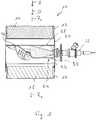
- the Fig. 1 shows a portion of an exhaust system generally designated 10 of a vehicle internal combustion engine.
- an upstream pipe section 12 of the Exhaust system 10 is in the in Fig. 1 illustrated embodiment, a diagrammatically shown only Dieseloxidationskatalysator 14 arranged.
- a catalyst assembly 18 is arranged to perform a selective reduction.
- a pipe section 20 is provided, in which a portion of a generally designated 22 exhaust duct of the exhaust system 10 is arranged.
- the exhaust gas A flowing in the exhaust system 10 and in the exhaust passage 22 flows substantially in the longitudinal direction of the pipe sections 12, 16 and 20 in an exhaust gas flow direction D.
- the exhaust gas flow direction represents a main flow direction of the exhaust gas A in the exhaust gas guide channel 22, which, caused by turbulence or flow deflections described below, can be superposed locally on other flow direction components.
- a reaction injector assembly also referred to as an injector, generally designated 26, which may be fixed to the pipe section 20, for example, and emits reactant R substantially orthogonal to the exhaust gas flow direction D.
- the reactant R admixed with the exhaust gas through the reagent injection assembly 26 may be, for example, a urea / water solution.
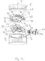
- the mixer 24 comprises a mixer body 32 constructed with two plate-like mixer parts 28, 30.
- the outer peripheral contour of the mixer body 32 is adapted to the cross-sectional contour of the exhaust gas guide channel 22, thus having a circular geometry, for example in adaptation to the internal cross-sectional geometry of the pipe section 20.
- the mixer 24 is positioned in the pipe section 20 such that the mixer body 32 covers substantially the entire inner cross-sectional area of the pipe section 20, but preferably at the outer peripheral region of the mixer body 32 leaves gap-like space to the inner surface of the pipe section 20 and there is flow around exhaust gas.
- the mixer body 32 may be fixed in the pipe section 20 by welding, for which purpose the two mixer body parts 28, 30, which are likewise to be fixed to one another, for example, by welding, are provided as sheet metal formed parts.
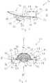
- the first mixer body part 28 oriented in the direction of the upstream of the exhaust gas guide channel 22, that is to say to be positioned oriented toward the diesel oxidation catalytic converter 14, has a first bulging region 34 that extends substantially past it. On both sides of this first bulge region 34, two substantially flat plate regions 36, 38 are provided.
- the first bulge region 34 is constructed with two first and second wall regions 40, 42 leading out of the plane defined by the plate regions 36, 38 and a third wall region 44 connecting them.
- the height of the first and second wall regions 40, 42 and thus also the height of the first bulge region 34 can vary across the first mixer body part 28 substantially transversely to the exhaust gas flow direction A.
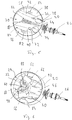
- a second bulge region 46 is provided in the second mixer body part 28.
- These two bulge regions 34, 46 together define a reagent receiving channel 48 which extends in the mixer body 32 of a in the Fig. 3 at the right-side reaction-receiving end region 50 to one in the Fig. 3 extending further left discharge end 52 extends.
- two third bulge regions 54, 56 are provided oriented substantially transversely to the second bulge region 50. Between the two third bulge regions 54, 56, a bulge region 60 providing a flow deflection region 58 is formed.
- a discharge channel 62 is limited, which is open via a discharge opening 64 to the outside.
- a dispensing channel 66 is bounded, which is open to the outside via a dispensing opening 68.
- the two discharge channels 62, 66 thus lead away from the reaction agent receiving channel 48 or its discharge end region 52 substantially transversely to a longitudinal direction of the reaction agent receiving channel between the Christsffenabilityend Scheme 50 and its discharge end 52 and are substantially separated from each other by the Strömungsumsch Scheme 58 or the Einwölbungs Scheme 60 providing ,
- the reaction agent receiving channel 48 extends from its adjoining the pipe section 20 positioned Christsstoffabilityend Scheme 50 substantially orthogonal to the exhaust gas flow direction D in the exhaust gas passage 22.
- the two extend from the reaction agent receiving channel 48 substantially transversely and in opposite directions extending discharge channels 62, 66 substantially orthogonal to the exhaust gas flow direction D in the exhaust gas guide channel 22.
- the reagent injection assembly 26 injects the reagent R in the form of an in Fig. 1 indicated spray cone with a direction of the exhaust gas flow direction D substantially orthogonal reagent flow direction in the reagent receiving channel 48 in the direction of the discharge end 52 to a.
- a first mixer body portion 28 to be provided upstream is provided formed generally 70 designated Abgaseintrittsö Stammsan eleven.
- the exhaust gas inlet opening arrangement 70 comprises a first group having two first exhaust gas inlet openings 72, 74, of which, for example, the larger first exhaust gas inlet opening lying closer to the reaction agent receiving end region 50 74 can extend into the third wall portion 44 into it.
- a second group with two second exhaust gas inlet openings 76, 78 is provided in the second wall region 42 substantially opposite the first wall region 40, wherein the configuration of the second exhaust gas inlet openings 76, 78 can be substantially symmetrical to the design of the first exhaust gas inlet openings 72, 74.
- the larger second exhaust gas inlet opening 78 can therefore extend into the region of the third wall region 44.
- the exhaust gas inlet opening arrangement 70 may further include a plurality of third exhaust gas inlet openings 80 in the third wall region 44, that is to say the wall area of the first bulge region 34 which delimits the reaction agent receiving channel 48 substantially in the direction upstream. These may extend distributed over the entire length of the reaction agent receiving channel 48 and generally have a significantly smaller opening cross-sectional area than the first exhaust gas inlet openings 72, 74 and the second exhaust gas inlet openings 76, 78th
- a plurality of fourth exhaust gas inlet openings 82, 84 are provided in association with the two discharge channels 62, 66 or their discharge openings 64, 68.
- the exhaust gas inlet openings 82 provided in association with the discharge channel 62 lie substantially in the region of the discharge opening 64 thereof, may still be partially positioned in the portion of the plate region 36 delimiting the discharge channel 62, but may also be partially positioned outside the discharge channel 62.
- exit opening arrangement 86 is provided in the second mixer body part 30 .
- This comprises at Einwölbungs Scheme 60 each associated with the discharge channel 62 and in association with the discharge channel 66 a plurality of outlet openings 88, 90 and includes in the Reactant receiving channel 48 in the direction of downstream limiting second bulge region 46 outlet openings 92nd
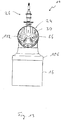
- the exhaust gas A to be flowed from upstream in the exhaust gas flow direction D on the mixer 24 may bypass the mixer body 32 at its outer peripheral portion due to the fitting of the mixer 24 into the pipe portion 20. Nevertheless, a large part of the exhaust gas A to be flowed initially to the mixer 24 in the exhaust gas flow direction D will enter the reagent receiving channel 48 through the first exhaust gas inlet openings 72, 74 and the second exhaust gas inlet openings 76, 78, ie substantially close to the reaction agent receiving end region 50 of the reaction agent receiving channel 48.
- the exhaust gas A as in Fig. 2 indicated by flow arrows P 1 , deflected.
- the exhaust gas A carries the reactant R injected in substantially the same flow direction from the reactant injection assembly 26 into the reactant receiving channel 48.
- the exhaust gas A carrying the reactant R impinges on the flow deflection region 58 and, as indicated by flow arrows P 2 in FIG Fig. 2 illustrated, deflected toward the two delivery channels 62, 66.
- the mixture of exhaust gas A and reagent R exits at the two oppositely oriented discharge ports 64, 68 from the discharge channels 62, 66 and, as indicated by flow arrows P 3 in Fig. 2 illustrated, initially further vortexed before it flows again substantially in the exhaust gas flow direction A to the catalyst assembly 18 to.
- a portion of the exhaust gas A enters via the third exhaust gas inlet openings 80 in the reaction agent receiving channel 48, which leads to an increased turbulence of the already flowing therein mixture of exhaust gas A and reagent R. Accordingly, this also leads via the fourth exhaust gas inlet openings 82, 84 in A portion of this mixture can also through the outlet openings 88, 90 at the Strömungsumsch Scheme 58 and the outlet openings 92 at the second bulge region 46 emerge.
- the mixer 24 shown in the figures and described above in detail can be varied in various areas without departing from the principles of the present invention.
- the dispensing channels 62,66 could be provided solely by such formations of the first mixer body part 28 and limited by substantially flat plate portions of the second mixer body part 30.
- the number of openings of the inlet opening arrangement 70 or the outlet opening arrangement 86 may differ from the number shown in the figures.
- no inlet openings could be formed in the third wall region 44.
- no outlet openings could be provided in the second bulge region 46.
- FIG. 7-15 Alternative embodiments of an exhaust system 10 designed with a mixer 24 constructed according to the invention are shown. While at the in Fig. 1 illustrated embodiment of an exhaust system 10, the exhaust gas flow direction R 1 upstream of the mixer 24, so z. For example, if the exhaust flow direction substantially in the diesel oxidation catalyst 14 is substantially rectified to an exhaust flow direction R 2 downstream of the mixer 24, these two system regions are flowed through by the exhaust gas in substantially the same main flow direction Fig. 8-11 illustrated embodiment of an exhaust system 10, these two flow direction in R 1 , R 2 directed to each other substantially opposite. Between the two pipe sections 12,16 may be provided generally designated 100 connecting housing, which connects to the mixer 24 containing pipe section 20 or at least partially also provides.
- the mixer 24 waste gas leaving A is deflected with respect to the exhaust gas flow direction R 1 approximately 90 °, passes through the connector housing and is deflected on entering the pipe section 16 again by approximately 90 ° so that in the pipe section 16, the exhaust gas flow direction R 2 of the exhaust gas flow direction R 1 in the pipe section 12 is directed approximately opposite. This results in a substantially folded overall structure of the exhaust system 10.
- FIGS. 12-15 show a structure in which the exhaust gas flow directions R 1 , R 2 are substantially orthogonal to each other upstream of the mixer 24 and upstream of the mixer 24 to each other.
- a connecting housing 102 which also provides, for example, the pipe section 20 containing the mixer 24 has connection areas 104, 106 for the pipe sections 12 and 16, respectively.
- the exhaust gas leaving the mixer 24 is approximately 90 ° deflected in the connection housing 102 with respect to the exhaust gas flow direction R and also enters the pipe section 16 in this direction. This results in a substantially angle-like overall structure of the exhaust system 10.
Landscapes
- Chemical & Material Sciences (AREA)
- Engineering & Computer Science (AREA)
- Chemical Kinetics & Catalysis (AREA)
- Combustion & Propulsion (AREA)
- Mechanical Engineering (AREA)
- General Engineering & Computer Science (AREA)
- Health & Medical Sciences (AREA)
- Toxicology (AREA)
- Dispersion Chemistry (AREA)
- Materials Engineering (AREA)
- Exhaust Gas After Treatment (AREA)
Description
- Die vorliegende Erfindung betrifft einen Mischer zur Durchmischung von in einem Abgaskanal einer Brennkraftmaschine strömenden Abgas mit in den Abgaskanal eingespritztem Reaktionsmittel gemäß dem Oberbegriff des Anspruchs 1.
- Um in Fahrzeugen mit Dieselantrieb den Schadstoffausstoß zu mindern, wird dem in einem Abgasführungskanal einer Abgasanlage strömenden Abgas ein Reaktionsmittel, beispielsweise eine Harnstoff/Wasser-Lösung, beigemischt. Um eine gute Durchmischung des durch eine Reaktionsmitteleinspritzanordnung, allgemein auch als Injektor bezeichnet, eingespritzten Reaktionsmittels mit dem Abgas zu erlangen, ist es bekannt, im Abgasführungskanal stromabwärts des Einspritzortes einen Mischer anzuordnen, welcher im Allgemeinen eine Mehrzahl von zur Abgasströmungsrichtung geneigt angeordneten Ablenkflächen aufweist, das Abgas und das Reaktionsmittel treffen auf diese Ablenkflächen auf und werden dort umgelenkt, so dass durch die dabei entstehende Verwirbelung eine verbesserte Vermischung erreicht wird. Gleichzeitig unterstützen die durch das Abgas erwärmten Ablenkflächen eines derartigen Mischers die Erwärmung und die Verdampfung des darauf auftreffenden, in Tröpfchenform in das Abgas eingespritzten Reaktionsmittels.
- Ein Mischer gemäß dem Oberbegriff des Anspruchs 1 ist aus der
DE 10 2013 223 033 A1 bekannt. Dieser Mischer umfasst drei in einem rohrartigen Gehäuse in Abgasströmungsrichtung aufeinanderfolgend mit Abstand zueinander angeordnete plattenartige Mischerkörperteile. In einem Bereich zwischen dem am weitesten stromaufwärts positionierten Mischerkörperteil und dem mittleren Mischerkörperteil ist ein Injektor zur Abgabe von Reaktionsmittel im Wesentlichen in den zwischen diesen beiden Mischerkörperteilen gebildeten Raumbereich vorgesehen. Das Reaktionsmittel und das in diesen Raumbereich durch Öffnungen im am weitesten stromaufwärts positionierten Mischerkörperteil einströmende Abgas strömen durch Öffnungen im mittleren Mischerkörperteil in einen zwischen diesem und dem am weitesten stromabwärts positionierten Mischerkörperteil gebildeten Raumbereich. - Aus der
WO 2015/187128 A1 ist ein Mischer bekannt, bei welchem in einem Abgasströmungsweg eine bereichsweise gewölbt ausgebildete Ablenkplatte mit einer Mehrzahl von Durchtrittsöffnungen für das Abgas vorgesehen ist. - Die
FR 2 966 197 A1 - Die
US 2014/0196441 A1 offenbart eine Mischeinrichtung für eine Abgasanlage, bei welcher ein Injektor Reaktionsmittel in einen von einer im Wesentlichen zylindrischen Wandung mit einer Vielzahl von darin ausgebildeten Öffnungen umgrenzten Raumbereich eingespritzt. - Es ist die Aufgabe der vorliegenden Erfindung, einen Mischer zur Durchmischung von in einem Abgaskanal einer Brennkraftmaschine strömendem Abgas mit in den Abgaskanal eingespritztem Reaktionsmittel vorzusehen, welcher eine effizientere Durchmischung des Reaktionsmittels mit dem Abgas herbeiführt.
- Erfindungsgemäß wird diese Aufgabe gelöst durch einen Mischer zur Durchmischung von in einem Abgasführungskanal einer Brennkraftmaschine strömendem Abgas mit in den Abgasführungskanal eingespritztem Reaktionsmittel gemäß Anspruch 1. Dieser Mischer umfasst einen Mischerkörper mit
- einem Reaktionsmittelaufnahmekanal,
- einer Abgaseintrittsöffnungsanordnung mit einer Mehrzahl von zu dem Reaktionsmittelaufnahmekanal führenden Abgaseintrittsöffnungen,
- wenigstens einem von dem Reaktionsmittelaufnahmekanal wegführenden Abgabekanal mit einer Abgabekanalöffnung zur Abgabe eines Reaktionsmittel/Abgas-Gemisches aus dem Mischerkörper.
- Der erfindungsgemäß aufgebaute Mischer weist in dem Mischerkörper, bereitgestellt durch den Reaktionsmittelaufnahmekanal und den wenigstens einen von diesem weg führenden Abgabekanal, einen Innenvolumenbereich auf, in welchen einerseits das Reaktionsmitteleingespritzt wird, nämlich in den Reaktionsmittelaufnahmekanal, und in welchen andererseits über die Abgaseintrittsöffnungsanordnung das in einem Abgasführungskanal einer Abgasanlage strömende Abgas eintritt. Sowohl beim Eintritt in den als auch beim Strömen durch den Reaktionsmittelaufnahmekanal und den wenigstens einen Abgabekanal wird die Strömungsrichtung des Abgases mehrfach umgelenkt, so dass durch diese Strömungsumlenkung beim Durchströmen des Reaktionsmittelaufnahmekanals und des wenigstens einen Abgabekanals eine effiziente Durchmischung des Reaktionsmittels mit dem Abgas erzwungen wird.
- Um dabei eine möglichst gleichmäßige Abgabe des in dem Mischerkörper generierten Gemisches aus Reaktionsmittel und Abgas in den stromabwärts folgenden Teil eines Abgasführungskanals zu erreichen, wird vorgeschlagen, dass von dem Reaktionsmittelaufnahmekanal zwei Abgabekanäle vorzugsweise in im Wesentlichen entgegengesetzten Richtungen wegführen.
- Der Reaktionsmittelaufnahmekanal kann einen Reaktionsmittelaufnahmeendbereich aufweisen, in welchen das durch eine Reaktionsmitteleinspritzanordnung abgegebene Reaktionsmittel eingespritzt werden kann. Das Reaktionsmittel strömt im Reaktionsmittelaufnahmekanal auf einen Abgabeendbereich desselben zu. Von diesem Abgabeendbereich des Reaktionsmittelaufnahmekanals führt der wenigstens eine Abgabekanal weg.
- Um im Übergang von dem Reaktionsmittelaufnahmekanal zu dem wenigstens einen Abgabekanal durch Strömungsumlenkung für eine effiziente Durchmischung sorgen zu können, wird vorgeschlagen, dass im Abgabeendbereich ein Strömungsumlenkbereich zum Umlenken von im Reaktionsmittelaufnahmekanal auf den Abgabeendbereich zu strömendem Reaktionsmittel oder/und Abgas in den wenigstens einen Abgabekanal vorgesehen ist. Wenn dabei der Strömungsumlenkbereich im Wesentlichen zwischen den beiden Abgabekanälen angeordnet ist, können diese einerseits strömungstechnisch voneinander entkoppelt werden, andererseits kann der Strömungsumlenkbereich zur Strömungsumlenkung in Zuordnung zu beiden Abgabekanälen genutzt werden.
- Um neben dem Austritt des Gemisches aus Reaktionsmittel und Abgas im Bereich der Abgabeöffnung des wenigstens einen Abgabekanals auch an anderen Orten einen Austritt dieses Gemisches aus dem Innenvolumenbereich des Mischerkörpers zu ermöglichen, wird vorgeschlagen, dass eine Austrittsöffnungsanordnung mit einer Mehrzahl von aus dem Reaktionsmittelaufnahmekanal oder/und dem wenigstens einen Abgabekanal herausführenden Austrittsöffnungen vorgesehen ist. Dabei kann beispielsweise vorgesehen sein, dass im Übergangsbereich von dem Reaktionsmittelaufnahmekanal zu einem der Abgabekanäle eine erste Gruppe von Austrittsöffnungen vorgesehen ist und im Übergangsbereich von dem Reaktionsmittelaufnahmekanal zu dem anderen der Abgabekanäle eine zweite Gruppe von Austrittsöffnungen vorgesehen ist.
- Um auch den Eintritt von Abgas in den Innenraum des Mischerkörpers an mehreren Positionen zu ermöglichen, wird vorgeschlagen, die Abgaseintrittsöffnungsanordnung in einem den Reaktionsmittelaufnahmekanal begrenzenden ersten Wandungsbereich des Mischerkörpers eine erste Gruppe mit wenigstens einer ersten Abgaseintrittsöffnung und in einem den Reaktionsmittelaufnahmekanal begrenzenden zweiten Wandungsbereich des Mischerkörpers eine zweite Gruppe mit wenigstens einer zweiten Abgaseintrittsöffnung umfasst. In einem zwischen dem ersten Wandungsbereich und dem zweiten Wandungsbereich liegenden und den Reaktionsmittelaufnahmekanal begrenzenden dritten Wandungsbereich kann beispielsweise eine Mehrzahl von dritten Abgaseintrittsöffnungen vorgesehen sein.
- Um dabei die größte Menge des in dem Innenraum des Mischerkörpers eintretenden Abgases über die erste Gruppe und die zweite Gruppe an zwei einander vorzugsweise im Wesentlichen gegenüberliegenden Wandungsbereichen, nämlich dem ersten Wandungsbereich und dem zweiten Wandungsbereich, erreichen zu können, wird vorgeschlagen, dass wenigstens eine, vorzugsweise jede erste Abgaseintrittsöffnung oder/und wenigstens eine, vorzugsweise jede zweite Abgaseintrittsöffnung eine größere Öffnungsquerschnittsfläche aufweist als wenigstens eine, vorzugsweise jede dritte Abgaseintrittsöffnung.
- Für eine weiter verbesserte Durchmischung des Abgases mit dem Reaktionsmittel kann vorgesehen sein, dass die Abgaseintrittsöffnungsanordnung in Zuordnung zu wenigstens einem vorzugsweise jedem Abgabekanal wenigstens eine, vorzugsweise eine Mehrzahl von vierten Abgaseintrittsöffnungen aufweist. Vorzugsweise ist dabei vorgesehen, dass die in Zuordnung zu wenigstens einem Abgabekanal vorgesehene wenigstens eine vierte Abgaseintrittsöffnung im Bereich der Abgabekanalöffnung dieses Abgabekanals zu dem Abgabekanal führt.
- Um den Mischerkörper mit dem darin vorzusehenden Innenvolumenbereich zur Bereitstellung des Reaktionsmittelaufnahmekanals und des wenigstens einen Abgabekanals in einfacher Weise aufbauen zu können, ist erfindungsgemäß vorgesehen, dass der Mischerkörper ein im Wesentlichen plattenartiges erstes Mischerkörperteil und ein mit den ersten Mischerkörperteil verbundenes, im Wesentlichen plattenartiges zweites Mischerkörperteil umfasst.
- Zur Bereitstellung des Innenvolumenbereichs umfasst das erste Mischerkörperteil einen den Reaktionsmittelaufnahmekanal begrenzenden ersten Auswölbungsbereich und beidseits des ersten Auswölbungsbereichs einen mit dem zweiten Mischerkörperteil verbundenen und optional einen Abgabekanal begrenzenden Plattenbereich. Das zweite Mischerkörperteil kann einen den Reaktionsmittelaufnahmekanal begrenzenden zweiten Auswölbungsbereich und einen den wenigstens einen Abgabekanal begrenzenden dritten Auswölbungsbereich umfassen.
- Der erste Auswölbungsbereich kann den ersten Wandungsbereich und den zweiten Wandungsbereich bereitstellen, welche einander im Wesentlichen gegenüberliegend angeordnet sein können, und kann den dritten Wandungsbereich bereitstellen, welcher zwischen dem ersten und dem zweiten Wandungsbereich diese verbindend angeordnet ist.
- Die Abgaseintrittsöffnungsanordnung kann im ersten Mischerkörperteil vorgesehen sein, welches somit ein im Wesentlichen in Richtung stromaufwärts orientiert zu positionierendes Mischerkörperteil ist. Die Austrittsöffnungsanordnung kann im zweiten Mischerkörperteil vorgesehen sein, welches somit im Wesentlichen in Richtung stromabwärts orientiert in einem Abgasführungskanal zu positionieren ist.
- Zur Bereitstellung des Strömungsumlenkbereichs zwischen dem Reaktionsmittelaufnahmekanal und dem wenigstens einen Abgabekanal kann im zweiten Mischerkörperteil ein Einwölbungsbereich vorgesehen sein.
- Die vorliegende Erfindung betrifft ferner eine Abgasanlage für eine Brennkraftmaschine, umfassend einen Abgasführungskanal, einen erfindungsgemäß aufgebauten Mischer und eine Reaktionsmitteleinspritzanordnung zum Einspritzen von Reaktionsmittel in den Reaktionsmittelaufnahmekanal des Mischers.
- Dabei ist vorzugsweise vorgesehen, dass der Mischer in dem Abgasführungskanal im Wesentlichen die gesamte Strömungsquerschnittsfläche des Abgasführungskanals bedeckt, so dass im Wesentlichen das gesamte den Abgasführungskanal durchströmende Abgas durch die in dem Mischerkörper gebildeten Abgaseintrittsöffnungen, entweder in den Innenraum des Mischerkörpers hinein oder durch den Mischerkörper hindurch strömen muss und im Wesentlichen keine Umströmung des Mischers an dessen Außenumfangsbereich ermöglicht ist.
- Der Mischer ist dabei vorzugsweise im Abgasführungskanal derart positioniert, dass der Reaktionsmittelaufnahmekanal oder/und der wenigstens eine Abgabekanal sich im Wesentlichen orthogonal zu einer Abgasströmungsrichtung im Abgasführungskanal erstreckt. Insbesondere bei derartiger Orientierung des Reaktionsmittelaufnahmekanals ist es besonders vorteilhaft, wenn die Reaktionsmitteleinspritzanordnung Reaktionsmittel im Wesentlichen orthogonal zur Abgasströmungsrichtung im Abgasführungskanal einspritzt.
- Bei der erfindungsgemäßen Abgasanlage kann stromaufwärts des Mischers eine Dieseloxidationskatalysatoranordnung vorgesehen sein. Stromabwärts des Mischers kann eine Katalysatoranordnung angeordnet sein, vermittels welcher auch unter der Wirkung des dem Abgas beigemischten Reaktionsmittels eine selektive Reduktion durchgeführt wird. Auch eine Partikelfilteranordnung kann stromabwärts des Mischers positioniert sein.
- Abhängig von der Einbaulage in ein Fahrzeug kann die erfindungsgemäße Abgasanlage dabei derart aufgebaut sein, dass eine Abgasströmungsrichtung in der Katalysatoranordnung oder/und der Partikelfilteranordnung und eine Abgasströmungsrichtung in der Dieseloxidationskatalysatoranordnung zueinander im Wesentlichen gleich gerichtet sind oder zueinander im Wesentlichen orthogonal sind oder einander im Wesentlichen entgegengesetzt gerichtet sind.
- Die vorliegende Erfindung wird nachfolgend mit Bezug auf die beiliegenden Figuren detailliert beschrieben. Es zeigt:
- Fig. 1
- eine schematische Längsschnittdarstellung eines Abschnitts eines in einer Abgasanlage gebildeten Abgasführungskanals mit einem Mischer und einer Reaktionsmittel in den Mischer einspritzenden Reaktionsmitteleinspritzanordnung;
- Fig. 2
- die Komponenten einer Abgasanlage gemäß
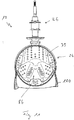
Fig. 1 in explosionsartiger Darstellung; - Fig. 3
- eine Seitenansicht des Mischers der Abgasanlage der
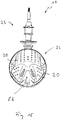
Fig. 1 , betrachtet in Blickrichtung III inFig. 4 ; - Fig. 4
- eine Seitenansicht des Mischers der Abgasanlage der
Fig. 1 , betrachtet in Blickrichtung IV inFig. 3 ; - Fig. 5
- eine perspektivische Ansicht eines in einem Abgasführungskanal positionierten Mischers, betrachtet in Blickrichtung V in
Fig. 4 ; - Fig. 6
- eine der
Fig. 5 entsprechende Ansicht bei Betrachtung des Mischers in Blickrichtung VI inFig. 4 ; - Fig.7
- eine Seitenansicht einer Abgasanlage;
- Fig. 8
- eine Draufsicht auf die Abgasanlage der
Fig. 7 , betrachtet in Blickrichtung VIII inFig. 7 ; - Fig. 9
- eine vergrößerte Detailansicht der Abgasanlage der
Fig. 7 , teilweise aufgeschnitten dargestellt; - Fig. 10
- eine Ansicht des Details der
Fig. 9 in Blickrichtung X inFig. 9 ; - Fig. 11
- eine Ansicht des Details der
Fig. 9 in Blickrichtung XI inFig. 9 ; - Fig. 12
- eine der
Fig. 7 entsprechende Ansicht einer alternativen Ausgestaltungsart einer Abgasanlage; - Fig. 13
- eine Ansicht der Abgasanlage der
Fig. 12 in Blickrichtung XIII inFig. 12 ; - Fig. 14
- eine Ansicht der Abgasanlage der
Fig. 12 in Blickrichtung XIV inFig. 12 ; - Fig. 15
- eine weitere Ansicht der Abgasanlage der
Fig. 12 in Blickrichtung XIII inFig. 12 . - Die
Fig. 1 zeigt einen Abschnitt einer allgemein mit 10 bezeichneten Abgasanlage einer Fahrzeugbrennkraftmaschine. In einem stromaufwärtigen Rohrabschnitt 12 der Abgasanlage 10 ist in dem inFig. 1 dargestellten Ausgestaltungsbeispiel ein nur schematisch dargestellter Dieseloxidationskatalysator 14 angeordnet. In einem stromabwärtigen Rohrabschnitt 16 der Abgasanlage 10 ist eine Katalysatoranordnung 18 zur Durchführung einer selektiven Reduktion angeordnet. - Zwischen den beiden Rohrabschnitten 12, 16 ist ein Rohrabschnitt 20 vorgesehen, in welchem ein Abschnitt eines allgemein mit 22 bezeichneten Abgasführungskanals der Abgasanlage 10 angeordnet ist. Das in der Abgasanlage 10 bzw. im Abgasführungskanal 22 strömende Abgas A strömt im Wesentlichen in der Längsrichtung der Rohrabschnitte 12, 16 und 20 in einer Abgasströmungsrichtung D. Es ist darauf hinzuweisen, dass die Abgasströmungsrichtung die eine Hauptströmungsrichtung des Abgases A im Abgasführungskanal 22 repräsentiert, welcher, hervorgerufen durch Turbulenzen oder nachfolgend beschriebene Strömungsumlenkungen, lokal andere Strömungsrichtungskomponente überlagert sein können.
- Im Rohrabschnitt 20 der Abgasanlage 10 ist ein allgemein mit 24 bezeichneter und nachfolgend mit Bezug auf die
Fig. 2 bis 6 detailliert beschriebener Mischer angeordnet. In Zuordnung zu dem Mischer 24 ist eine allgemein mit 26 bezeichnete Reaktionsmitteleinspritzanordnung, auch als Injektor bezeichnet, vorgesehen, welche beispielsweise an dem Rohrabschnitt 20 festgelegt sein kann und Reaktionsmittel R im Wesentlichen orthogonal zur Abgasströmungsrichtung D abgibt. Das durch die Reaktionsmitteleinspritzanordnung 26 dem Abgas beigemischte Reaktionsmittel R kann beispielsweise eine Harnstoff/Wasser-Lösung sein. - Der Mischer 24 umfasst einen mit zwei plattenartigen Mischerteilen 28, 30 aufgebauten Mischerkörper 32. Die Außenumfangskontur des Mischerkörpers 32 ist an die Querschnittskontur des Abgasführungskanals 22 angepasst, weist also beispielsweise in Anpassung an die Innenquerschnittsgeometrie des Rohrabschnitts 20 eine kreisrunde Geometrie auf. Wie die
Fig. 1 ,5 und 6 dies zeigen, ist der Mischer 24 im Rohrabschnitt 20 derart positioniert, dass der Mischerkörper 32 im Wesentlichen die gesamte Innenquerschnittsfläche des Rohrabschnitts 20 bedeckt, am Außenumfangsbereich der Mischerkörper 32 vorzugsweise jedoch einen spaltartigen Zwischenraum zur Innenoberfläche des Rohrabschnitts 20 belässt und dort von Abgas umströmbar ist. Beispielsweise kann der Mischerkörper 32 in dem Rohrabschnitt 20 durch Verschweißung festgelegt sein, wozu vorteilhafterweise die beiden beispielsweise ebenfalls durch Verschweißung aneinander festzulegenden Mischerkörperteile 28, 30 als Blechumformteile bereitgestellt sind. - Das im Abgasführungskanal 22 in Richtung stromaufwärts orientiert, also dem Dieseloxidationskatalysator 14 zugewandt orientiert zu positionierende erste Mischerkörperteil 28 weist einen im Wesentlichen über dieses sich hinweg erstreckenden ersten Auswölbungsbereich 34 auf. Beidseits dieses ersten Auswölbungsbereichs 34 sind zwei im Wesentlichen ebene Plattenbereiche 36, 38 vorgesehen. Der erste Auswölbungsbereich 34 ist mit zwei einander im Wesentlichen gegenüberliegenden und aus der durch die Plattenbereiche 36, 38 aufgespannten Ebene heraus führenden ersten und zweiten Wandungsbereichen 40, 42 und einem diese verbindenden dritten Wandungsbereich 44 aufgebaut. Die Höhe der ersten und zweiten Wandungsbereiche 40, 42 und somit auch die Höhe des ersten Auswölbungsbereichs 34 kann über das erste Mischerkörperteil 28 hinweg im Wesentlichen quer zur Abgasströmungsrichtung A variieren.
- In Zuordnung zu dem ersten Auswölbungsbereich 44 ist im zweiten Mischerkörperteil 28 ein zweiter Auswölbungsbereich 46 vorgesehen. Diese beiden Auswölbungsbereiche 34, 46 umgrenzen zusammen einen Reaktionsmittelaufnahmekanal 48, welcher sich in dem Mischerkörper 32 von einem in der
Fig. 3 rechts liegenden Reaktionsmittelaufnahmeendbereich 50 zu einem in derFig. 3 weiter links liegenden Abgabeendbereich 52 erstreckt. - Im zweiten Mischerkörperteil 30 sind im Wesentlichen quer zum zweiten Auswölbungsbereich 50 orientiert zwei dritte Auswölbungsbereiche 54, 56 vorgesehen. Zwischen den beiden dritten Auswölbungsbereichen 54, 56 ist ein einen Strömungsumlenkbereich 58 bereitstellender Einwölbungsbereich 60 gebildet.
- Zwischen dem dritten Auswölbungsbereich 54 des zweiten Mischerkörperteils 30 und dem Plattenbereich 36 des ersten Mischerkörperteils 28 ist ein Abgabekanal 62 begrenzt, der über eine Abgabeöffnung 64 nach außen offen ist. In entsprechender Weise ist zwischen dem dritten Auswölbungsbereich 56 des zweiten Mischerkörperteils 30 und dem Plattenbereich 38 des ersten Mischerkörperteils 28 ein Abgabekanal 66 begrenzt, der über eine Abgabeöffnung 68 nach außen offen ist. Die beiden Abgabekanäle 62, 66 führen also vom Reaktionsmittelaufnahmekanal 48 bzw. dessen Abgabeendbereich 52 im Wesentlichen quer zu einer Längserstreckungsrichtung des Reaktionsmittelaufnahmekanals zwischen dessen Reaktionsmittelaufnahmeendbereich 50 und dessen Abgabeendbereich 52 weg und sind durch den Strömungsumlenkbereich 58 bzw. den diesen bereitstellenden Einwölbungsbereich 60 im Wesentlichen voneinander getrennt. Bei Positionierung des Mischers 24 im Rohrabschnitt 20 in der in
Fig. 5 und inFig. 6 dargestellten Art und Weise erstreckt sich der Reaktionsmittelaufnahmekanal 48 ausgehend von seinem angrenzend an den Rohrabschnitt 20 positionierten Reaktionsmittelaufnahmeendbereich 50 im Wesentlichen orthogonal zur Abgasströmungsrichtung D im Abgasführungskanal 22. Entsprechend erstrecken sich auch die beiden vom Reaktionsmittelaufnahmekanal 48 im Wesentlichen quer und in zueinander entgegengesetzten Richtung weg erstreckenden Abgabekanäle 62, 66 im Wesentlichen orthogonal zur Abgasströmungsrichtung D im Abgasführungskanal 22. Die Reaktionsmitteleinspritzanordnung 26 spritzt das Reaktionsmittel R in Form eines inFig. 1 angedeuteten Sprühkegels mit einer zur Abgasströmungsrichtung D im Wesentlichen orthogonalen Reaktionsmittelströmungsrichtung in den Reaktionsmittelaufnahmekanal 48 in Richtung auf den Abgabeendbereich 52 zu ein. - Um den Eintritt von auf den Mischer 24 in der Abgasströmungsrichtung D zu strömendem Abgas A in den im Wesentlichen den Reaktionsmittelaufnahmekanal 48 und die beiden Abgabekanäle 54, 56 umfassenden Innenraum des Mischerkörpers 32 zu ermöglichen, ist an dem in Richtung stromaufwärts orientiert vorzusehenden ersten Mischerkörperteil 28 eine allgemein mit 70 bezeichnete Abgaseintrittsöffnungsanordnung ausgebildet. Die Abgaseintrittsöffnungsanordnung 70 umfasst im ersten Wandungsbereich 40 eine erste Gruppe mit zwei ersten Abgaseintrittsöffnungen 72, 74, von welchen beispielsweise die näher am Reaktionsmittelaufnahmeendbereich 50 liegende größere erste Abgaseintrittsöffnung 74 sich bis in den dritten Wandungsbereich 44 hinein erstrecken kann. In dem dem ersten Wandungsbereich 40 im Wesentlichen gegenüberliegenden zweiten Wandungsbereich 42 ist eine zweite Gruppe mit zwei zweiten Abgaseintrittsöffnungen 76, 78 vorgesehen, wobei die Ausgestaltung der zweiten Abgaseintrittsöffnungen 76, 78 im Wesentlichen symmetrisch zur Ausgestaltung der ersten Abgaseintrittsöffnungen 72, 74 sein kann. Auch hier kann sich also die größere zweite Abgaseintrittsöffnung 78 bis in den Bereich des dritten Wandungsbereichs 44 erstrecken.
- Die Abgaseintrittsöffnungsanordnung 70 kann ferner im dritten Wandungsbereich 44, also dem den Reaktionsmittelaufnahmekanal 48 im Wesentlichen in Richtung stromaufwärts begrenzenden Wandungsbereich des ersten Auswölbungsbereichs 34, eine Mehrzahl dritter Abgaseintrittsöffnungen 80 umfassen. Diese können sich über die gesamte Länge des Reaktionsmittelaufnahmekanals 48 verteilt erstrecken und weisen im Allgemeinen eine deutlich kleinere Öffnungsquerschnittsfläche auf, als die ersten Abgaseintrittsöffnungen 72, 74 und die zweiten Abgaseintrittsöffnungen 76, 78.
- Beidseits des ersten Auswölbungsbereichs 34, also im Wesentlichen in den Plattenbereichen 36, 38, sind in Zuordnung zu den beiden Abgabekanälen 62, 66 bzw. deren Abgabeöffnungen 64, 68 jeweils mehrere vierte Abgaseintrittsöffnungen 82, 84 vorgesehen. Die in Zuordnung zum Abgabekanal 62 vorgesehenen Abgaseintrittsöffnungen 82 liegen im Wesentlichen im Bereich der Abgabeöffnung 64 desselben, können zum Teil noch in dem den Abgabekanal 62 begrenzenden Abschnitt des Plattenbereichs 36 positioniert sein, können zum Teil aber auch außerhalb des Abgabekanals 62 positioniert sein. Entsprechendes gilt für die in Zuordnung zu dem Abgabekanal 66 vorgesehenen vierten Abgaseintrittsöffnungen 84.
- Im zweiten Mischerkörperteil 30 ist eine in
Fig. 6 deutlich sichtbare Austrittsöffnungsanordnung 86 vorgesehen. Diese umfasst am Einwölbungsbereich 60 jeweils in Zuordnung zum Abgabekanal 62 und in Zuordnung zum Abgabekanal 66 mehrere Austrittsöffnungen 88, 90 und umfasst in dem den Reaktionsmittelaufnahmekanal 48 in Richtung stromabwärts begrenzenden zweiten Auswölbungsbereich 46 Austrittsöffnungen 92. - Das von stromaufwärts in der Abgasströmungsrichtung D auf dem Mischer 24 zu strömende Abgas A kann aufgrund der Einpassung des Mischers 24 in den Rohrabschnitt 20 den Mischerkörper 32 an seinem Außenumfangsbereich umströmen. Gleichwohl wird ein Großteil des zunächst in der Abgasströmungsrichtung D auf den Mischer 24 zu strömenden Abgases A durch die ersten Abgaseintrittsöffnungen 72, 74 und die zweiten Abgaseintrittsöffnungen 76, 78, also im Wesentlichen nahe am Reaktionsmittelaufnahmeendbereich 50 des Reaktionsmittelaufnahmekanals 48 in den Reaktionsmittelaufnahmekanal 48 eintreten. Dazu wird das Abgas A, so wie in
Fig. 2 durch Strömungspfeile P1 angedeutet, umgelenkt. Das in den Reaktionsmittelaufnahmekanal 48 nahe dessen Reaktionsmittelaufnahmeendbereich 50 eintretende Abgas A durchströmt den Reaktionsmittelaufnahmekanal 48 in Richtung vom Reaktionsmittelaufnahmeendbereich 50 auf den Abgabeendbereich 52 bzw. den dort vorgesehenen Strömungsumlenkbereich 58 zu. Dabei nimmt das Abgas A das im Wesentlichen in der gleichen Strömungsrichtung von der Reaktionsmitteleinspritzanordnung 26 in den Reaktionsmittelaufnahmekanal 48 eingespritzte Reaktionsmittel R mit. Am Abgabeendbereich 52 trifft das das Reaktionsmittel R mitführende Abgas A auf den Strömungsumlenkbereich 58 auf und wird, wie durch Strömungspfeile P2 inFig. 2 veranschaulicht, in Richtung zu den beiden Abgabekanälen 62, 66 abgelenkt. Das Gemisch aus Abgas A und Reaktionsmittel R tritt an den beiden einander entgegengesetzt orientierten Abgabeöffnungen 64, 68 aus den Abgabekanälen 62, 66 aus und wird, wie durch Strömungspfeile P3 inFig. 2 veranschaulicht, zunächst noch weiter verwirbelt, bevor es im Wesentlichen wieder in der Abgasströmungsrichtung A auf die Katalysatoranordnung 18 zu strömt. - Ein Teil des Abgases A tritt über die dritten Abgaseintrittsöffnungen 80 in den Reaktionsmittelaufnahmekanal 48 ein, was zu einer verstärkten Verwirbelung des darin bereits strömenden Gemisches aus Abgas A und Reaktionsmittel R führt. Entsprechend führt auch das über die vierten Abgaseintrittsöffnungen 82, 84 im Bereich der Abgabeöffnungen 64, 68 das erste Mischerkörperteil 28 durchströmende Abgas A zu einer verstärkten Verwirbelung bzw. Strömungsumlenkung des aus den Abgabeöffnungen 64, 68 austretenden Gemisches aus Reaktionsmittel R und Abgas A. Ein Teil dieses Gemisches kann auch durch die Austrittsöffnungen 88, 90 am Strömungsumlenkbereich 58 bzw. die Austrittsöffnungen 92 am zweiten Auswölbungsbereich 46 austreten.
- Der in den Figuren dargestellte und vorangehend detailliert beschriebene Mischer 24 kann, ohne von den Prinzipien der vorliegenden Erfindung abzuweichen, in verschiedensten Bereichen variiert werden. So könnten beispielsweise die beiden Plattenbereiche 36, 38 dort, wo sie die Abgabekanäle 62, 66 mit begrenzen, Auswölbungsbereiche aufweisen, um den Strömungsquerschnitt der Abgabekanäle 62, 66 zu vergrößern. Auch könnten die Abgabekanäle 62,66 ausschließlich durch solche Ausformungen des ersten Mischerkörperteils 28 bereitgestellt und durch im Wesentlichen ebene Plattenbereiche des zweiten Mischerkörperteils 30 begrenzt sein. Die Anzahl der Öffnungen der Eintrittsöffnungsanordnung 70 bzw. der Austrittsöffnungsanordnung 86 kann von der in den Figuren dargestellten Anzahl abweichen. Auch könnten beispielsweise im dritten Wandungsbereich 44 keine Eintrittsöffnungen ausgebildet sein. Ebenso könnten im zweiten Auswölbungsbereich 46 keine Austrittsöffnungen vorgesehen sein.
- In den
Fig. 7-15 sind alternative Ausgestaltungen einer mit einem erfindungsgemäß aufgebauten Mischer 24 ausgebildeten Abgasanlage 10 dargestellt. Während bei der inFig. 1 dargestellten Ausgestaltung einer Abgasanlage 10 die Abgasströmungsrichtung R1 stromaufwärts des Mischers 24, also z. B. die im Wesentlichen im Dieseloxidationskatalysator 14 sich einstellende Abgasströmungsrichtung, zu einer stromabwärts des Mischers 24 sich einstellenden Abgasströmungsrichtung R2 im Wesentlichen gleichgerichtet ist, diese beiden Systembereiche vom Abgas also im Wesentlichen der gleichen Hauptströmungsrichtung durchströmt werden, sind in dem in denFig. 8-11 dargestellten Ausgestaltungsbeispiel einer Abgasanlage 10 diese beiden Strömungsrichtung in R1, R2 zueinander im Wesentlichen entgegengesetzt gerichtet. Zwischen den beiden Rohrabschnitten 12,16 kann ein allgemein mit 100 bezeichnetes Verbindungsgehäuse vorgesehen sein, welches an den den Mischer 24 enthaltenden Rohrabschnitt 20 anschließt oder diesen zumindest teilweise auch bereitstellt. Das den Mischer 24 verlassende Abgas A wird bezüglich der Abgasströmungsrichtung R1 näherungsweise um 90° umgelenkt, durchströmt das Verbindungsgehäuse und wird beim Eintritt in den Rohrabschnitt 16 erneut um näherungsweise 90° umgelenkt, so dass im Rohrabschnitt 16 die Abgasströmungsrichtung R2 der Abgasströmungsrichtung R1 im Rohrabschnitt 12 näherungsweise entgegengesetzt gerichtet ist. Es ergibt sich somit eine im Wesentlichen gefaltete Gesamtstruktur der Abgasanlage 10. - Die
Figuren 12-15 zeigen einen Aufbau, bei welchem die Abgasströmungsrichtungen R1, R2 stromaufwärts des Mischers 24 und stromaufwärts des Mischers 24 zueinander im Wesentlichen orthogonal stehen. Ein beispielsweise auch den den Mischer 24 enthaltenden Rohrabschnitt 20 bereitstellendes Verbindungsgehäuse 102 weist Anschlussbereiche 104, 106 für die Rohrabschnitte 12 bzw. 16 auf. - Das den Mischer 24 verlassende Abgas wird im Verbindungsgehäuse 102 bezüglich der Abgasströmungsrichtung R näherungsweise um 90° umgelenkt und tritt in dieser Richtung auch in den Rohrabschnitt 16 ein. Es ergibt sich somit eine im Wesentlichen winkelartige Gesamtstruktur der Abgasanlage 10.
- Es ist abschließend darauf hinzuweisen, dass die vorangehend angesprochenen Abgasströmungsrichtungen R1, R2 jeweils die in einem angesprochenen Systembereich sich einstellenden Hauptströmungsrichtungen bezeichnen. Dies schließt nicht aus, dass in diesen Systembereichen lokal von diesen Hauptströmungsrichtungen abweichende Strömungsrichtungen auftreten können.
Claims (19)
- Mischer zur Durchmischung von in einem Abgasführungskanal einer Brennkraftmaschine strömendem Abgas (A) mit in den Abgasführungskanal eingespritztem Reaktionsmittel (R), umfassend einen Mischerkörper (32) mit- einem Reaktionsmittelaufnahmekanal (48),- einer Abgaseintrittsöffnungsanordnung (70) mit einer Mehrzahl von zu dem Reaktionsmittelaufnahmekanal führenden Abgaseintrittsöffnungen (72, 74, 76, 78, 80),- wenigstens einem von dem Reaktionsmittelaufnahmekanal (48) wegführenden Abgabekanal (62, 66) mit einer Abgabekanalöffnung (64, 68) zur Abgabe eines Reaktionsmittel/Abgas-Gemisches aus dem Mischerkörper (32)wobei der Mischerkörper (32) ein plattenartiges erstes Mischerkörperteil (28) und ein plattenartiges zweites Mischerkörperteil (30) umfasst,
dadurch gekennzeichnet, dass das erste Mischerkörperteil (28) einen den Reaktionsmittelaufnahmekanal (48) begrenzenden ersten Auswölbungsbereich (34) und beidseits des ersten Auswölbungsbereichs (34) einen mit dem zweiten Mischerkörperteil (30) verbundenen Plattenbereich (36, 38) umfasst, und dass das zweite Mischerkörperteil (30) einen den Reaktionsmittelaufnahmekanal (48) begrenzenden zweiten Auswölbungsbereich (46) und einen den wenigstens einen Abgabekanal (62, 66) begrenzenden dritten Auswölbungsbereich (54, 56) umfasst. - Mischer nach Anspruch 1, dadurch gekennzeichnet, dass von dem Reaktionsmittelaufnahmekanal (48) zwei Abgabekanäle (62, 66) vorzugsweise in im Wesentlichen entgegengesetzten Richtungen wegführen.
- Mischer noch Anspruch 1 oder 2, dadurch gekennzeichnet, dass der Reaktionsmittelaufnahmekanal (48) einen Reaktionsmittelaufnahmeendbereich (50) und einen Abgabeendbereich (52) aufweist, wobei der wenigstens eine Abgabekanal (62, 66) von dem Reaktionsmittelaufnahmekanal (48) im Abgabeendbereich (52) wegführt.
- Mischer nach Anspruch 3, dadurch gekennzeichnet, dass im Abgabeendbereich (52) ein Strömungsumlenkbereich (58) zum Umlenken von im Reaktionsmittelaufnahmekanal (48) auf den Abgabeendbereich (52) zu strömendem Reaktionsmittel (R) oder/und Abgas (A) in den wenigstens einen Abgabekanal (62, 66) vorgesehen ist.
- Mischer nach Anspruch 2 und Anspruch 4 dadurch gekennzeichnet, dass der Strömungsumlenkbereich (58) im Wesentlichen zwischen den beiden Abgabekanälen (62, 66) angeordnet ist.
- Mischer nach einem der Ansprüche 1-5, dadurch gekennzeichnet, dass eine Austrittsöffnungsanordnung (86) mit einer Mehrzahl von aus dem Reaktionsmittelaufnahmekanal (48) oder/und dem wenigstens einen Abgabekanal (62, 66) herausführenden Austrittsöffnungen (88, 90, 92) vorgesehen ist.
- Mischer nach Anspruch 2 und Anspruch 6, dadurch gekennzeichnet, dass im Übergangsbereich von dem Reaktionsmittelaufnahmekanal (48) zu einem der Abgabekanäle (62, 66) eine erste Gruppe von Austrittsöffnungen (88) vorgesehen ist und im Übergangsbereich von dem Reaktionsmittelaufnahmekanal (48) zu dem anderen der Abgabekanäle (62, 66) eine zweite Gruppe von Austrittsöffnungen (90) vorgesehen ist.
- Mischer nach einem der Ansprüche 1-7, dadurch gekennzeichnet, dass die Abgaseintrittsöffnungsanordnung (70) in einem den Reaktionsmittelaufnahmekanal (48) begrenzenden ersten Wandungsbereich (40) des Mischerkörpers (32) eine erste Gruppe mit wenigstens einer ersten Abgaseintrittsöffnung (72, 74) und in einem den Reaktionsmittelaufnahmekanal (48) begrenzenden zweiten Wandungsbereich (42) des Mischerkörpers (32) eine zweite Gruppe mit wenigstens einer zweiten Abgaseintrittsöffnung (76, 78) umfasst, wobei vorzugsweise die Abgaseintrittsöffnungsanordnung (70) in einem zwischen dem ersten Wandungsbereich (40) und dem zweiten Wandungsbereich (42) liegenden und den Reaktionsmittelaufnahmekanal (48) begrenzenden dritten Wandungsbereich (44) dritte Abgaseintrittsöffnungen (80) umfasst.
- Mischer nach Anspruch 8, dadurch gekennzeichnet, dass wenigstens eine, vorzugsweise jede erste Abgaseintrittsöffnung (72, 74) oder/und wenigstens eine, vorzugsweise jede zweite Abgaseintrittsöffnung (76, 78) eine größere Öffnungsquerschnittsfläche aufweist als wenigstens eine, vorzugsweise jede dritte Abgaseintrittsöffnung (80).
- Mischer nach einem der Ansprüche 1-9, dadurch gekennzeichnet, dass die Abgaseintrittsöffnungsanordnung (70) in Zuordnung zu wenigstens einem vorzugsweise jedem Abgabekanal (62, 66) wenigstens eine, vorzugsweise eine Mehrzahl von vierten Abgaseintrittsöffnungen (82, 84) aufweist.
- Mischer nach Anspruch 10, dadurch gekennzeichnet, dass die in Zuordnung zu wenigstens einem Abgabekanal (62, 66) vorgesehene wenigstens eine vierte Abgaseintrittsöffnung (82, 84) im Bereich der Abgabekanalöffnung (64, 68) dieses Abgabekanals (62, 66) zu dem Abgabekanal (62, 66) führt.
- Mischer nach einem der Ansprüche 1-11, dadurch gekennzeichnet, dass der Plattenbereich (36, 38) einen Abgabekanal (62, 66) begrenzt.
- Mischer nach Anspruch 8 und Anspruch 12, dadurch gekennzeichnet, dass der erste Auswölbungsbereich (34) den ersten Wandungsbereich (40), den zweiten Wandungsbereich (42) und den dritten Wandungsbereich (44) bereitstellt.
- Mischer nach einem der Ansprüche 1-13, dadurch gekennzeichnet, dass die Abgaseintrittsöffnungsanordnung (70) im ersten Mischerkörperteil (28) vorgesehen ist, oder/und dass die Austrittsöffnungsanordnung (86) im zweiten Mischerkörperteil (30) vorgesehen ist.
- Mischer nach Anspruch 4 und einem der Ansprüche 5-14, dadurch gekennzeichnet, dass im zweiten Mischerkörperteil (30) ein den Strömungsumlenkbereich (58) bereitstellender Einwölbungsbereich (60) vorgesehen ist.
- Abgasanlage für eine Brennkraftmaschine, umfassend einen Abgasführungskanal (22), einen Mischer (24) nach einem der vorangehenden Ansprüche und eine Reaktionsmitteleinspritzanordnung (26) zum Einspritzen von Reaktionsmittel (R) in den Reaktionsmittelaufnahmekanal (48) des Mischers (24).
- Abgasanlage nach Anspruch 16, dadurch gekennzeichnet, dass der Mischer (24) in dem Abgasführungskanal (22) im Wesentlichen die gesamte Strömungsquerschnittfläche des Abgasführungskanals (22) bedeckt, oder/und dass der Reaktionsmittelaufnahmekanal (48) oder/und der wenigstens eine Abgabekanal (62, 66) sich im Wesentlichen orthogonal zu einer Abgasströmungsrichtung (D) im Abgasführungskanal (22) erstreckt, oder/und dass die Reaktionsmitteleinspritzanordnung (26) Reaktionsmittel (R) im Wesentlichen orthogonal zu der Abgasströmungsrichtung (D) im Abgasführungskanal (22) einspritzt.
- Abgasanlage nach Anspruch 16 oder 17, dadurch gekennzeichnet, dass stromaufwärts des Mischers (24) eine Dieseloxidationskatalysatoranordnung (14) vorgesehen, oder/und dass stromabwärts des Mischers (24) eine Katalysatoranordnung (18) zur selektiven Reduktion oder/und eine Partikelfilteranordnung vorgesehen ist.
- Abgasanlage nach Anspruch 18, dadurch gekennzeichnet, dass eine Abgasströmungsrichtung (R2) in der Katalysatoranordnung (18) oder/und der Partikelfilteranordnung und eine Abgasströmungsrichtung (R1) in der Dieseloxidationskatalysatoranordnung (14) zueinander im Wesentlichen gleich gerichtet sind oder zueinander im Wesentlichen orthogonal sind oder einander im Wesentlichen entgegengesetzt gerichtet sind.
Applications Claiming Priority (1)
| Application Number | Priority Date | Filing Date | Title |
|---|---|---|---|
| DE102016104361.3A DE102016104361A1 (de) | 2016-03-10 | 2016-03-10 | Mischer |
Publications (3)
| Publication Number | Publication Date |
|---|---|
| EP3216992A1 EP3216992A1 (de) | 2017-09-13 |
| EP3216992B1 true EP3216992B1 (de) | 2018-10-31 |
| EP3216992B2 EP3216992B2 (de) | 2026-04-08 |
Family
ID=58261530
Family Applications (1)
| Application Number | Title | Priority Date | Filing Date |
|---|---|---|---|
| EP17159284.3A Active EP3216992B2 (de) | 2016-03-10 | 2017-03-06 | Mischer |
Country Status (4)
| Country | Link |
|---|---|
| US (1) | US10215076B2 (de) |
| EP (1) | EP3216992B2 (de) |
| CN (1) | CN107178406B (de) |
| DE (1) | DE102016104361A1 (de) |
Families Citing this family (22)
| Publication number | Priority date | Publication date | Assignee | Title |
|---|---|---|---|---|
| US10179315B2 (en) | 2015-06-12 | 2019-01-15 | Donaldson Company, Inc. | Exhaust treatment device |
| EP3492718B1 (de) * | 2017-11-30 | 2020-06-10 | Katcon Global S.A. | Abgasleitung für ein fahrzeug |
| DE102018101253A1 (de) * | 2018-01-22 | 2019-07-25 | Eberspächer Exhaust Technology GmbH & Co. KG | Mischer |
| DE102018114755A1 (de) | 2018-06-20 | 2019-12-24 | Eberspächer Exhaust Technology GmbH & Co. KG | Mischer |
| DE102018119578A1 (de) | 2018-08-13 | 2020-02-13 | Eberspächer Exhaust Technology GmbH & Co. KG | Mischer |
| DE102018130716A1 (de) * | 2018-12-03 | 2020-06-04 | Friedrich Boysen Gmbh & Co. Kg | Vorrichtung zum Einbringen und Verteilen eines fließfähigen Zusatzstoffs in einen Abgasstrom |
| DE102019104772A1 (de) | 2019-01-08 | 2020-07-09 | Eberspächer Exhaust Technology GmbH & Co. KG | Abgasanlage |
| EP3680462B1 (de) | 2019-01-08 | 2023-12-13 | Purem GmbH | Abgasanlage |
| DE102019101678A1 (de) * | 2019-01-24 | 2020-07-30 | Eberspächer Exhaust Technology GmbH & Co. KG | Mischer |
| DE102019109983A1 (de) * | 2019-04-16 | 2020-10-22 | Eberspächer Exhaust Technology GmbH & Co. KG | Mischer |
| EP3760846A1 (de) * | 2019-07-04 | 2021-01-06 | Donaldson Company, Inc. | System zum mischen eines flüssigsprays in einen gasförmigen strom und abgasnachbehandlungsvorrichtung damit |
| US11840952B2 (en) | 2019-07-11 | 2023-12-12 | Donaldson Company, Inc. | Dosing conduit arrangements for exhaust aftertreatment system |
| EP3792462A1 (de) | 2019-09-13 | 2021-03-17 | Donaldson Company, Inc. | Dosier- und mischanordnungen für ein abgasnachbehandlungssystem |
| DE102019127882A1 (de) * | 2019-10-16 | 2021-04-22 | Eberspächer Exhaust Technology GmbH | Mischeranordnung |
| EP3812557B1 (de) | 2019-10-22 | 2023-01-25 | Purem GmbH | Mischer |
| JP7152385B2 (ja) * | 2019-12-27 | 2022-10-12 | フタバ産業株式会社 | 排気ガス浄化装置及び旋回流発生部材 |
| DE102020101134A1 (de) * | 2020-01-20 | 2021-07-22 | Eberspächer Exhaust Technology GmbH | Gas/Gas-Mischer zum Einleiten von Gas in den Abgasstrom einer Brennkraftmaschine |
| FR3111384B1 (fr) * | 2020-06-12 | 2022-08-05 | Faurecia Systemes Dechappement | Mélangeur de réducteur pour gaz d’échappement |
| US11585255B2 (en) * | 2020-11-23 | 2023-02-21 | Faurecia Emissions Control Technologies, Usa, Llc | Crowned inlet baffle for high efficiency mixer |
| WO2022178231A1 (en) | 2021-02-19 | 2022-08-25 | Purem Novi, Inc. | Exhaust aftertreatment apparatus |
| DE102021105724A1 (de) * | 2021-03-10 | 2022-09-15 | Purem GmbH | Abgas/Reaktionsmittel-Mischanordnung |
| JP2025171357A (ja) * | 2024-05-09 | 2025-11-20 | いすゞ自動車株式会社 | 排気処理装置 |
Citations (17)
| Publication number | Priority date | Publication date | Assignee | Title |
|---|---|---|---|---|
| DE19820990A1 (de) | 1998-05-11 | 1999-11-18 | Babcock Anlagen Gmbh | Vorrichtung in einer Anlage zur Reduktion von Stickoxiden |
| US20100083643A1 (en) | 2007-03-12 | 2010-04-08 | Miwa Hayashi | Exhaust gas purification apparatus for internal combustion engine |
| FR2947003A1 (fr) | 2009-06-19 | 2010-12-24 | Faurecia Sys Echappement | Ligne d'echappement avec systeme d'injection |
| US8033104B2 (en) | 2008-07-09 | 2011-10-11 | Ford Global Technologies, Llc | Selective catalytic reduction (SCR) catalyst injection systems |
| FR2966197A1 (fr) | 2010-10-18 | 2012-04-20 | Faurecia Sys Echappement | Ligne d'echappement pour vehicule automobile. |
| WO2012080585A1 (fr) | 2010-12-15 | 2012-06-21 | Faurecia Systemes D'echappement | Ligne d'échappement avec dispositif d'injection de réactif gazeux |
| EP2670016A2 (de) | 2012-05-29 | 2013-12-04 | LSIS Co., Ltd. | Vorrichtung zur photovoltaischen Energieerzeugung und Verfahren dafür |
| US20140196441A1 (en) | 2013-01-17 | 2014-07-17 | Komatsu Ltd. | Reductant aqueous solution mixing device and exhaust aftertreatment device provided with the same |
| WO2015012829A1 (en) | 2013-07-25 | 2015-01-29 | Faurecia Emissions Control Technologies, Usa, Llc | Mixer with swirl box for a vehicle exhaust system |
| US20150110681A1 (en) | 2013-10-22 | 2015-04-23 | Eberspacher Exhaust Technology GmbH & Co. KG | Catalytic converter device with injection section |
| DE102013223033A1 (de) | 2013-11-12 | 2015-05-13 | Eberspächer Exhaust Technology GmbH & Co. KG | Katalysatoranordnung mit Injektionsabschnitt |
| DE112012006960T5 (de) | 2012-09-28 | 2015-07-02 | Faurecia Emissions Control Technologies, Usa, Llc | Abgasanlage-Mischeinrichtung mit Impaktor |
| FR3020835A1 (fr) | 2014-05-07 | 2015-11-13 | Faurecia Sys Echappement | Ensemble de purification de gaz d'echappement et ligne d'echappement comprenant un tel ensemble |
| WO2015187128A1 (en) | 2014-06-03 | 2015-12-10 | Faurecia Emissions Control Technologies, Usa, Llc | Mixer and doser cone assembly |
| EP3018311A1 (de) | 2014-11-06 | 2016-05-11 | Eberspächer Exhaust Technology GmbH & Co. KG | Injektionsabschnitt für eine abgasnachbehandlungseinrichtung |
| WO2016176076A1 (en) | 2015-04-30 | 2016-11-03 | Faurecia Emissions Control Technologies, Usa, Llc | Full rotation mixer |
| WO2016201441A2 (en) | 2015-06-12 | 2016-12-15 | Donaldson Company, Inc. | Exhaust treatment device |
Family Cites Families (9)
| Publication number | Priority date | Publication date | Assignee | Title |
|---|---|---|---|---|
| US7278389B2 (en) | 2005-04-19 | 2007-10-09 | Murat Kirakosyan | Automobile intake air flow plenum and plenum diverter |
| DE102008028625B4 (de) | 2008-04-21 | 2011-12-15 | Tenneco Gmbh | Verfahren zum Vermischen eines Abgasstromes |
| DE102010034705A1 (de) * | 2010-08-18 | 2012-02-23 | Emitec Gesellschaft Für Emissionstechnologie Mbh | Kompakte Abgasbehandlungseinheit mit Reaktionsmittelzugabe |
| FR3010137B1 (fr) | 2013-08-30 | 2016-08-26 | Faurecia Systemes D'echappement | Dispositif de purification de gaz d'echappement de moteur a combustion interne |
| DE102014205158A1 (de) * | 2014-03-19 | 2015-09-24 | Eberspächer Exhaust Technology GmbH & Co. KG | Mischer für eine Abgasanlage |
| US9828897B2 (en) * | 2015-04-30 | 2017-11-28 | Faurecia Emissions Control Technologies Usa, Llc | Mixer for a vehicle exhaust system |
| US10040028B2 (en) * | 2015-11-04 | 2018-08-07 | Ford Global Technologies, Llc | Methods and systems for a mixer |
| US10035102B2 (en) * | 2015-11-18 | 2018-07-31 | Ford Global Technologies, Llc | System for a urea mixer |
| US9932875B2 (en) * | 2016-03-02 | 2018-04-03 | Ford Global Technologies, Llc | Mixer for mixing exhaust gas |
-
2016
- 2016-03-10 DE DE102016104361.3A patent/DE102016104361A1/de active Pending
-
2017
- 2017-03-06 CN CN201710126242.9A patent/CN107178406B/zh active Active
- 2017-03-06 EP EP17159284.3A patent/EP3216992B2/de active Active
- 2017-03-09 US US15/454,215 patent/US10215076B2/en active Active
Patent Citations (19)
| Publication number | Priority date | Publication date | Assignee | Title |
|---|---|---|---|---|
| DE19820990A1 (de) | 1998-05-11 | 1999-11-18 | Babcock Anlagen Gmbh | Vorrichtung in einer Anlage zur Reduktion von Stickoxiden |
| US20100083643A1 (en) | 2007-03-12 | 2010-04-08 | Miwa Hayashi | Exhaust gas purification apparatus for internal combustion engine |
| US8033104B2 (en) | 2008-07-09 | 2011-10-11 | Ford Global Technologies, Llc | Selective catalytic reduction (SCR) catalyst injection systems |
| FR2947003A1 (fr) | 2009-06-19 | 2010-12-24 | Faurecia Sys Echappement | Ligne d'echappement avec systeme d'injection |
| DE112010002589T5 (de) | 2009-06-19 | 2012-11-29 | Faurecia Systemes D'echappement | Abgasstrang mit Einspritzsystem |
| FR2966197A1 (fr) | 2010-10-18 | 2012-04-20 | Faurecia Sys Echappement | Ligne d'echappement pour vehicule automobile. |
| WO2012080585A1 (fr) | 2010-12-15 | 2012-06-21 | Faurecia Systemes D'echappement | Ligne d'échappement avec dispositif d'injection de réactif gazeux |
| EP2670016A2 (de) | 2012-05-29 | 2013-12-04 | LSIS Co., Ltd. | Vorrichtung zur photovoltaischen Energieerzeugung und Verfahren dafür |
| DE112012006960T5 (de) | 2012-09-28 | 2015-07-02 | Faurecia Emissions Control Technologies, Usa, Llc | Abgasanlage-Mischeinrichtung mit Impaktor |
| US20150240689A1 (en) | 2012-09-28 | 2015-08-27 | Faurecia Emissions Control Technologies, Usa, Llc | Exhaust system mixer with impactor |
| US20140196441A1 (en) | 2013-01-17 | 2014-07-17 | Komatsu Ltd. | Reductant aqueous solution mixing device and exhaust aftertreatment device provided with the same |
| WO2015012829A1 (en) | 2013-07-25 | 2015-01-29 | Faurecia Emissions Control Technologies, Usa, Llc | Mixer with swirl box for a vehicle exhaust system |
| US20150110681A1 (en) | 2013-10-22 | 2015-04-23 | Eberspacher Exhaust Technology GmbH & Co. KG | Catalytic converter device with injection section |
| DE102013223033A1 (de) | 2013-11-12 | 2015-05-13 | Eberspächer Exhaust Technology GmbH & Co. KG | Katalysatoranordnung mit Injektionsabschnitt |
| FR3020835A1 (fr) | 2014-05-07 | 2015-11-13 | Faurecia Sys Echappement | Ensemble de purification de gaz d'echappement et ligne d'echappement comprenant un tel ensemble |
| WO2015187128A1 (en) | 2014-06-03 | 2015-12-10 | Faurecia Emissions Control Technologies, Usa, Llc | Mixer and doser cone assembly |
| EP3018311A1 (de) | 2014-11-06 | 2016-05-11 | Eberspächer Exhaust Technology GmbH & Co. KG | Injektionsabschnitt für eine abgasnachbehandlungseinrichtung |
| WO2016176076A1 (en) | 2015-04-30 | 2016-11-03 | Faurecia Emissions Control Technologies, Usa, Llc | Full rotation mixer |
| WO2016201441A2 (en) | 2015-06-12 | 2016-12-15 | Donaldson Company, Inc. | Exhaust treatment device |
Also Published As
| Publication number | Publication date |
|---|---|
| EP3216992B2 (de) | 2026-04-08 |
| DE102016104361A1 (de) | 2017-09-14 |
| US10215076B2 (en) | 2019-02-26 |
| EP3216992A1 (de) | 2017-09-13 |
| CN107178406B (zh) | 2019-10-01 |
| US20170260888A1 (en) | 2017-09-14 |
| CN107178406A (zh) | 2017-09-19 |
Similar Documents
| Publication | Publication Date | Title |
|---|---|---|
| EP3216992B1 (de) | Mischer | |
| EP1151184B1 (de) | Abgassystem mit wenigstens einer leitfläche | |
| EP2233709B1 (de) | Abgasbehandlungseinrichtung | |
| DE102020124106A1 (de) | Kraftfahrzeugabgasnachbehandlungssystem | |
| DE102019120994A1 (de) | Strömungsumleiter mit internem kasten für eine mischerbaugruppe eines fahrzeugauspuffsystems | |
| EP2610457B1 (de) | Abgasbehandlungsvorrichtung | |
| DE112017007996T5 (de) | Einspritzdüsenkegel nach Art einer Venturidüse | |
| DE102011108237A1 (de) | Anordnung zum Einbringen eines Zusatzstoffes in einen Gasstrom | |
| EP3757364B1 (de) | Mischer für eine scr-abgasbehandlungsanlage | |
| DE102011013335A1 (de) | Abgasanlage einer Brennkraftmaschine | |
| DE102007002981B4 (de) | Statischer Mischer für eine Abgasanlage eines brennkraftmaschinenbetriebenen Fahrzeugs, insbesondere Kraftfahrzeugs | |
| EP4086439A1 (de) | Abgasbehandlungsmodul | |
| EP3611354B1 (de) | Mischer | |
| EP4382730B1 (de) | Abgasbehandlungsanordnung | |
| WO2015022187A1 (de) | Abgasbehandlungseinheit mit strömungsteilenden und -mischenden leitelementen | |
| EP3851646B1 (de) | Gas/gas-mischer zum einleiten von gas in den abgasstrom einer brennkraftmaschine | |
| DE102019104772A1 (de) | Abgasanlage | |
| DE102011120221A1 (de) | Mischer für eine Abgasanlage und Abgasanlage | |
| EP4080025B1 (de) | Abgas/reaktionsmittel-mischanordnung | |
| DE102016014966A1 (de) | Abgasnachbehandlungseinrichtung für einen Kraftwagen | |
| EP3812557B1 (de) | Mischer | |
| DE102022132126A1 (de) | Abgasbehandlungsanordnung | |
| EP4166225B1 (de) | Mischer | |
| EP3680462B1 (de) | Abgasanlage | |
| EP4390068B1 (de) | Mischsektion für eine abgasanlage einer brennkraftmaschine |
Legal Events
| Date | Code | Title | Description |
|---|---|---|---|
| PUAI | Public reference made under article 153(3) epc to a published international application that has entered the european phase |
Free format text: ORIGINAL CODE: 0009012 |
|
| STAA | Information on the status of an ep patent application or granted ep patent |
Free format text: STATUS: THE APPLICATION HAS BEEN PUBLISHED |
|
| AK | Designated contracting states |
Kind code of ref document: A1 Designated state(s): AL AT BE BG CH CY CZ DE DK EE ES FI FR GB GR HR HU IE IS IT LI LT LU LV MC MK MT NL NO PL PT RO RS SE SI SK SM TR |
|
| AX | Request for extension of the european patent |
Extension state: BA ME |
|
| STAA | Information on the status of an ep patent application or granted ep patent |
Free format text: STATUS: REQUEST FOR EXAMINATION WAS MADE |
|
| 17P | Request for examination filed |
Effective date: 20180112 |
|
| RBV | Designated contracting states (corrected) |
Designated state(s): AL AT BE BG CH CY CZ DE DK EE ES FI FR GB GR HR HU IE IS IT LI LT LU LV MC MK MT NL NO PL PT RO RS SE SI SK SM TR |
|
| REG | Reference to a national code |
Ref country code: DE Ref legal event code: R079 Ref document number: 502017000295 Country of ref document: DE Free format text: PREVIOUS MAIN CLASS: F01N0003200000 Ipc: F01N0003021000 |
|
| RIC1 | Information provided on ipc code assigned before grant |
Ipc: F01N 3/10 20060101ALI20180507BHEP Ipc: B01F 5/04 20060101ALI20180507BHEP Ipc: F01N 3/021 20060101AFI20180507BHEP Ipc: B01F 5/00 20060101ALI20180507BHEP Ipc: F01N 3/20 20060101ALI20180507BHEP Ipc: F01N 3/28 20060101ALI20180507BHEP Ipc: B01F 3/04 20060101ALI20180507BHEP Ipc: B01F 5/06 20060101ALI20180507BHEP Ipc: F01N 13/18 20100101ALI20180507BHEP |
|
| GRAP | Despatch of communication of intention to grant a patent |
Free format text: ORIGINAL CODE: EPIDOSNIGR1 |
|
| STAA | Information on the status of an ep patent application or granted ep patent |
Free format text: STATUS: GRANT OF PATENT IS INTENDED |
|
| INTG | Intention to grant announced |
Effective date: 20180622 |
|
| GRAS | Grant fee paid |
Free format text: ORIGINAL CODE: EPIDOSNIGR3 |
|
| GRAA | (expected) grant |
Free format text: ORIGINAL CODE: 0009210 |
|
| STAA | Information on the status of an ep patent application or granted ep patent |
Free format text: STATUS: THE PATENT HAS BEEN GRANTED |
|
| AK | Designated contracting states |
Kind code of ref document: B1 Designated state(s): AL AT BE BG CH CY CZ DE DK EE ES FI FR GB GR HR HU IE IS IT LI LT LU LV MC MK MT NL NO PL PT RO RS SE SI SK SM TR |
|
| REG | Reference to a national code |
Ref country code: GB Ref legal event code: FG4D Free format text: NOT ENGLISH Ref country code: CH Ref legal event code: EP |
|
| REG | Reference to a national code |
Ref country code: AT Ref legal event code: REF Ref document number: 1059673 Country of ref document: AT Kind code of ref document: T Effective date: 20181115 |
|
| REG | Reference to a national code |
Ref country code: IE Ref legal event code: FG4D Free format text: LANGUAGE OF EP DOCUMENT: GERMAN |
|
| REG | Reference to a national code |
Ref country code: DE Ref legal event code: R096 Ref document number: 502017000295 Country of ref document: DE |
|
| REG | Reference to a national code |
Ref country code: SE Ref legal event code: TRGR |
|
| REG | Reference to a national code |
Ref country code: NL Ref legal event code: MP Effective date: 20181031 |
|
| REG | Reference to a national code |
Ref country code: LT Ref legal event code: MG4D |
|
| PG25 | Lapsed in a contracting state [announced via postgrant information from national office to epo] |
Ref country code: NO Free format text: LAPSE BECAUSE OF FAILURE TO SUBMIT A TRANSLATION OF THE DESCRIPTION OR TO PAY THE FEE WITHIN THE PRESCRIBED TIME-LIMIT Effective date: 20190131 Ref country code: LV Free format text: LAPSE BECAUSE OF FAILURE TO SUBMIT A TRANSLATION OF THE DESCRIPTION OR TO PAY THE FEE WITHIN THE PRESCRIBED TIME-LIMIT Effective date: 20181031 Ref country code: IS Free format text: LAPSE BECAUSE OF FAILURE TO SUBMIT A TRANSLATION OF THE DESCRIPTION OR TO PAY THE FEE WITHIN THE PRESCRIBED TIME-LIMIT Effective date: 20190228 Ref country code: BG Free format text: LAPSE BECAUSE OF FAILURE TO SUBMIT A TRANSLATION OF THE DESCRIPTION OR TO PAY THE FEE WITHIN THE PRESCRIBED TIME-LIMIT Effective date: 20190131 Ref country code: ES Free format text: LAPSE BECAUSE OF FAILURE TO SUBMIT A TRANSLATION OF THE DESCRIPTION OR TO PAY THE FEE WITHIN THE PRESCRIBED TIME-LIMIT Effective date: 20181031 Ref country code: HR Free format text: LAPSE BECAUSE OF FAILURE TO SUBMIT A TRANSLATION OF THE DESCRIPTION OR TO PAY THE FEE WITHIN THE PRESCRIBED TIME-LIMIT Effective date: 20181031 Ref country code: LT Free format text: LAPSE BECAUSE OF FAILURE TO SUBMIT A TRANSLATION OF THE DESCRIPTION OR TO PAY THE FEE WITHIN THE PRESCRIBED TIME-LIMIT Effective date: 20181031 Ref country code: PL Free format text: LAPSE BECAUSE OF FAILURE TO SUBMIT A TRANSLATION OF THE DESCRIPTION OR TO PAY THE FEE WITHIN THE PRESCRIBED TIME-LIMIT Effective date: 20181031 Ref country code: FI Free format text: LAPSE BECAUSE OF FAILURE TO SUBMIT A TRANSLATION OF THE DESCRIPTION OR TO PAY THE FEE WITHIN THE PRESCRIBED TIME-LIMIT Effective date: 20181031 |
|
| PG25 | Lapsed in a contracting state [announced via postgrant information from national office to epo] |
Ref country code: GR Free format text: LAPSE BECAUSE OF FAILURE TO SUBMIT A TRANSLATION OF THE DESCRIPTION OR TO PAY THE FEE WITHIN THE PRESCRIBED TIME-LIMIT Effective date: 20190201 Ref country code: NL Free format text: LAPSE BECAUSE OF FAILURE TO SUBMIT A TRANSLATION OF THE DESCRIPTION OR TO PAY THE FEE WITHIN THE PRESCRIBED TIME-LIMIT Effective date: 20181031 Ref country code: PT Free format text: LAPSE BECAUSE OF FAILURE TO SUBMIT A TRANSLATION OF THE DESCRIPTION OR TO PAY THE FEE WITHIN THE PRESCRIBED TIME-LIMIT Effective date: 20190301 Ref country code: RS Free format text: LAPSE BECAUSE OF FAILURE TO SUBMIT A TRANSLATION OF THE DESCRIPTION OR TO PAY THE FEE WITHIN THE PRESCRIBED TIME-LIMIT Effective date: 20181031 Ref country code: AL Free format text: LAPSE BECAUSE OF FAILURE TO SUBMIT A TRANSLATION OF THE DESCRIPTION OR TO PAY THE FEE WITHIN THE PRESCRIBED TIME-LIMIT Effective date: 20181031 |
|
| REG | Reference to a national code |
Ref country code: DE Ref legal event code: R026 Ref document number: 502017000295 Country of ref document: DE |
|
| PG25 | Lapsed in a contracting state [announced via postgrant information from national office to epo] |
Ref country code: DK Free format text: LAPSE BECAUSE OF FAILURE TO SUBMIT A TRANSLATION OF THE DESCRIPTION OR TO PAY THE FEE WITHIN THE PRESCRIBED TIME-LIMIT Effective date: 20181031 Ref country code: CZ Free format text: LAPSE BECAUSE OF FAILURE TO SUBMIT A TRANSLATION OF THE DESCRIPTION OR TO PAY THE FEE WITHIN THE PRESCRIBED TIME-LIMIT Effective date: 20181031 |
|
| PLBI | Opposition filed |
Free format text: ORIGINAL CODE: 0009260 |
|
| PLAX | Notice of opposition and request to file observation + time limit sent |
Free format text: ORIGINAL CODE: EPIDOSNOBS2 |
|
| PG25 | Lapsed in a contracting state [announced via postgrant information from national office to epo] |
Ref country code: SM Free format text: LAPSE BECAUSE OF FAILURE TO SUBMIT A TRANSLATION OF THE DESCRIPTION OR TO PAY THE FEE WITHIN THE PRESCRIBED TIME-LIMIT Effective date: 20181031 Ref country code: EE Free format text: LAPSE BECAUSE OF FAILURE TO SUBMIT A TRANSLATION OF THE DESCRIPTION OR TO PAY THE FEE WITHIN THE PRESCRIBED TIME-LIMIT Effective date: 20181031 Ref country code: RO Free format text: LAPSE BECAUSE OF FAILURE TO SUBMIT A TRANSLATION OF THE DESCRIPTION OR TO PAY THE FEE WITHIN THE PRESCRIBED TIME-LIMIT Effective date: 20181031 Ref country code: SK Free format text: LAPSE BECAUSE OF FAILURE TO SUBMIT A TRANSLATION OF THE DESCRIPTION OR TO PAY THE FEE WITHIN THE PRESCRIBED TIME-LIMIT Effective date: 20181031 |
|
| 26 | Opposition filed |
Opponent name: TENNECO GMBH Effective date: 20190730 Opponent name: FAURECIA SYSTEMES D'ECHAPPEMENT Effective date: 20190730 |
|
| PLBB | Reply of patent proprietor to notice(s) of opposition received |
Free format text: ORIGINAL CODE: EPIDOSNOBS3 |
|
| PG25 | Lapsed in a contracting state [announced via postgrant information from national office to epo] |
Ref country code: MC Free format text: LAPSE BECAUSE OF FAILURE TO SUBMIT A TRANSLATION OF THE DESCRIPTION OR TO PAY THE FEE WITHIN THE PRESCRIBED TIME-LIMIT Effective date: 20181031 Ref country code: SI Free format text: LAPSE BECAUSE OF FAILURE TO SUBMIT A TRANSLATION OF THE DESCRIPTION OR TO PAY THE FEE WITHIN THE PRESCRIBED TIME-LIMIT Effective date: 20181031 |
|
| PG25 | Lapsed in a contracting state [announced via postgrant information from national office to epo] |
Ref country code: LU Free format text: LAPSE BECAUSE OF NON-PAYMENT OF DUE FEES Effective date: 20190306 |
|
| REG | Reference to a national code |
Ref country code: BE Ref legal event code: MM Effective date: 20190331 |
|
| PG25 | Lapsed in a contracting state [announced via postgrant information from national office to epo] |
Ref country code: IE Free format text: LAPSE BECAUSE OF NON-PAYMENT OF DUE FEES Effective date: 20190306 |
|
| PG25 | Lapsed in a contracting state [announced via postgrant information from national office to epo] |
Ref country code: BE Free format text: LAPSE BECAUSE OF NON-PAYMENT OF DUE FEES Effective date: 20190331 |
|
| PG25 | Lapsed in a contracting state [announced via postgrant information from national office to epo] |
Ref country code: TR Free format text: LAPSE BECAUSE OF FAILURE TO SUBMIT A TRANSLATION OF THE DESCRIPTION OR TO PAY THE FEE WITHIN THE PRESCRIBED TIME-LIMIT Effective date: 20181031 |
|
| PG25 | Lapsed in a contracting state [announced via postgrant information from national office to epo] |
Ref country code: MT Free format text: LAPSE BECAUSE OF FAILURE TO SUBMIT A TRANSLATION OF THE DESCRIPTION OR TO PAY THE FEE WITHIN THE PRESCRIBED TIME-LIMIT Effective date: 20181031 |
|
| REG | Reference to a national code |
Ref country code: CH Ref legal event code: PL |
|
| PG25 | Lapsed in a contracting state [announced via postgrant information from national office to epo] |
Ref country code: LI Free format text: LAPSE BECAUSE OF NON-PAYMENT OF DUE FEES Effective date: 20200331 Ref country code: CH Free format text: LAPSE BECAUSE OF NON-PAYMENT OF DUE FEES Effective date: 20200331 |
|
| PG25 | Lapsed in a contracting state [announced via postgrant information from national office to epo] |
Ref country code: CY Free format text: LAPSE BECAUSE OF FAILURE TO SUBMIT A TRANSLATION OF THE DESCRIPTION OR TO PAY THE FEE WITHIN THE PRESCRIBED TIME-LIMIT Effective date: 20181031 |
|
| REG | Reference to a national code |
Ref country code: DE Ref legal event code: R082 Ref document number: 502017000295 Country of ref document: DE Representative=s name: RUTTENSPERGER LACHNIT TROSSIN GOMOLL, PATENT- , DE Ref country code: DE Ref legal event code: R081 Ref document number: 502017000295 Country of ref document: DE Owner name: PUREM GMBH, DE Free format text: FORMER OWNER: EBERSPAECHER EXHAUST TECHNOLOGY GMBH & CO. KG, 66539 NEUNKIRCHEN, DE |
|
| PG25 | Lapsed in a contracting state [announced via postgrant information from national office to epo] |
Ref country code: HU Free format text: LAPSE BECAUSE OF FAILURE TO SUBMIT A TRANSLATION OF THE DESCRIPTION OR TO PAY THE FEE WITHIN THE PRESCRIBED TIME-LIMIT; INVALID AB INITIO Effective date: 20170306 |
|
| RAP2 | Party data changed (patent owner data changed or rights of a patent transferred) |
Owner name: PUREM GMBH |
|
| REG | Reference to a national code |
Ref country code: GB Ref legal event code: 732E Free format text: REGISTERED BETWEEN 20210902 AND 20210908 |
|
| RDAF | Communication despatched that patent is revoked |
Free format text: ORIGINAL CODE: EPIDOSNREV1 |
|
| APAH | Appeal reference modified |
Free format text: ORIGINAL CODE: EPIDOSCREFNO |
|
| APBM | Appeal reference recorded |
Free format text: ORIGINAL CODE: EPIDOSNREFNO |
|
| APBP | Date of receipt of notice of appeal recorded |
Free format text: ORIGINAL CODE: EPIDOSNNOA2O |
|
| APBQ | Date of receipt of statement of grounds of appeal recorded |
Free format text: ORIGINAL CODE: EPIDOSNNOA3O |
|
| PG25 | Lapsed in a contracting state [announced via postgrant information from national office to epo] |
Ref country code: MK Free format text: LAPSE BECAUSE OF FAILURE TO SUBMIT A TRANSLATION OF THE DESCRIPTION OR TO PAY THE FEE WITHIN THE PRESCRIBED TIME-LIMIT Effective date: 20181031 |
|
| REG | Reference to a national code |
Ref country code: AT Ref legal event code: MM01 Ref document number: 1059673 Country of ref document: AT Kind code of ref document: T Effective date: 20220306 |
|
| APAH | Appeal reference modified |
Free format text: ORIGINAL CODE: EPIDOSCREFNO |
|
| PG25 | Lapsed in a contracting state [announced via postgrant information from national office to epo] |
Ref country code: AT Free format text: LAPSE BECAUSE OF NON-PAYMENT OF DUE FEES Effective date: 20220306 |
|
| PLAB | Opposition data, opponent's data or that of the opponent's representative modified |
Free format text: ORIGINAL CODE: 0009299OPPO |
|
| APBU | Appeal procedure closed |
Free format text: ORIGINAL CODE: EPIDOSNNOA9O |
|
| R26 | Opposition filed (corrected) |
Opponent name: TENNECO GMBH Effective date: 20190730 |
|
| PGFP | Annual fee paid to national office [announced via postgrant information from national office to epo] |
Ref country code: IT Payment date: 20250331 Year of fee payment: 9 |
|
| APAH | Appeal reference modified |
Free format text: ORIGINAL CODE: EPIDOSCREFNO |
|
| APBP | Date of receipt of notice of appeal recorded |
Free format text: ORIGINAL CODE: EPIDOSNNOA2O |
|
| APBU | Appeal procedure closed |
Free format text: ORIGINAL CODE: EPIDOSNNOA9O |
|
| PUAH | Patent maintained in amended form |
Free format text: ORIGINAL CODE: 0009272 |
|
| STAA | Information on the status of an ep patent application or granted ep patent |
Free format text: STATUS: PATENT MAINTAINED AS AMENDED |
|
| REG | Reference to a national code |
Ref country code: CH Ref legal event code: M12 Free format text: ST27 STATUS EVENT CODE: U-0-0-M10-M12 (AS PROVIDED BY THE NATIONAL OFFICE) Effective date: 20260311 |
|
| PGFP | Annual fee paid to national office [announced via postgrant information from national office to epo] |
Ref country code: SE Payment date: 20260323 Year of fee payment: 10 |
|
| 27A | Patent maintained in amended form |
Effective date: 20260408 |
|
| AK | Designated contracting states |
Kind code of ref document: B2 Designated state(s): AL AT BE BG CH CY CZ DE DK EE ES FI FR GB GR HR HU IE IS IT LI LT LU LV MC MK MT NL NO PL PT RO RS SE SI SK SM TR |
|
| REG | Reference to a national code |
Ref country code: DE Ref legal event code: R102 Ref document number: 502017000295 Country of ref document: DE |
|
| PGFP | Annual fee paid to national office [announced via postgrant information from national office to epo] |
Ref country code: GB Payment date: 20260324 Year of fee payment: 10 |
|
| PGFP | Annual fee paid to national office [announced via postgrant information from national office to epo] |
Ref country code: DE Payment date: 20260320 Year of fee payment: 10 |
|
| PGFP | Annual fee paid to national office [announced via postgrant information from national office to epo] |
Ref country code: FR Payment date: 20260324 Year of fee payment: 10 |