EP3216425A1 - Articulation - Google Patents
Articulation Download PDFInfo
- Publication number
- EP3216425A1 EP3216425A1 EP16159418.9A EP16159418A EP3216425A1 EP 3216425 A1 EP3216425 A1 EP 3216425A1 EP 16159418 A EP16159418 A EP 16159418A EP 3216425 A1 EP3216425 A1 EP 3216425A1
- Authority
- EP
- European Patent Office
- Prior art keywords
- joint
- locking
- hinge
- receiving
- component
- Prior art date
- Legal status (The legal status is an assumption and is not a legal conclusion. Google has not performed a legal analysis and makes no representation as to the accuracy of the status listed.)
- Granted
Links
- 238000000034 method Methods 0.000 claims description 18
- 210000000988 bone and bone Anatomy 0.000 description 10
- 238000003780 insertion Methods 0.000 description 9
- 230000037431 insertion Effects 0.000 description 9
- 210000000629 knee joint Anatomy 0.000 description 7
- 208000037873 arthrodesis Diseases 0.000 description 6
- 206010061218 Inflammation Diseases 0.000 description 4
- 238000010276 construction Methods 0.000 description 4
- 230000004054 inflammatory process Effects 0.000 description 4
- 230000007794 irritation Effects 0.000 description 4
- 210000001519 tissue Anatomy 0.000 description 4
- 230000000295 complement effect Effects 0.000 description 3
- 239000007943 implant Substances 0.000 description 3
- 210000002310 elbow joint Anatomy 0.000 description 2
- 238000002513 implantation Methods 0.000 description 2
- 210000001503 joint Anatomy 0.000 description 2
- 239000002245 particle Substances 0.000 description 2
- 230000035515 penetration Effects 0.000 description 2
- 238000000926 separation method Methods 0.000 description 2
- 239000013589 supplement Substances 0.000 description 2
- 241001465754 Metazoa Species 0.000 description 1
- 230000009286 beneficial effect Effects 0.000 description 1
- 230000001419 dependent effect Effects 0.000 description 1
- 230000000694 effects Effects 0.000 description 1
- 210000003414 extremity Anatomy 0.000 description 1
- 230000035876 healing Effects 0.000 description 1
- 208000015181 infectious disease Diseases 0.000 description 1
- 210000003127 knee Anatomy 0.000 description 1
- 210000003041 ligament Anatomy 0.000 description 1
- 238000003801 milling Methods 0.000 description 1
- 238000002324 minimally invasive surgery Methods 0.000 description 1
- 238000009420 retrofitting Methods 0.000 description 1
- 210000004872 soft tissue Anatomy 0.000 description 1
- 230000003313 weakening effect Effects 0.000 description 1
Images


Classifications
-
- A—HUMAN NECESSITIES
- A61—MEDICAL OR VETERINARY SCIENCE; HYGIENE
- A61F—FILTERS IMPLANTABLE INTO BLOOD VESSELS; PROSTHESES; DEVICES PROVIDING PATENCY TO, OR PREVENTING COLLAPSING OF, TUBULAR STRUCTURES OF THE BODY, e.g. STENTS; ORTHOPAEDIC, NURSING OR CONTRACEPTIVE DEVICES; FOMENTATION; TREATMENT OR PROTECTION OF EYES OR EARS; BANDAGES, DRESSINGS OR ABSORBENT PADS; FIRST-AID KITS
- A61F2/00—Filters implantable into blood vessels; Prostheses, i.e. artificial substitutes or replacements for parts of the body; Appliances for connecting them with the body; Devices providing patency to, or preventing collapsing of, tubular structures of the body, e.g. stents
- A61F2/02—Prostheses implantable into the body
- A61F2/30—Joints
- A61F2/38—Joints for elbows or knees
- A61F2/3836—Special connection between upper and lower leg, e.g. constrained
- A61F2/384—Special connection between upper and lower leg, e.g. constrained hinged, i.e. with transverse axle restricting the movement
- A61F2/385—Special connection between upper and lower leg, e.g. constrained hinged, i.e. with transverse axle restricting the movement also provided with condylar bearing surfaces
-
- A—HUMAN NECESSITIES
- A61—MEDICAL OR VETERINARY SCIENCE; HYGIENE
- A61F—FILTERS IMPLANTABLE INTO BLOOD VESSELS; PROSTHESES; DEVICES PROVIDING PATENCY TO, OR PREVENTING COLLAPSING OF, TUBULAR STRUCTURES OF THE BODY, e.g. STENTS; ORTHOPAEDIC, NURSING OR CONTRACEPTIVE DEVICES; FOMENTATION; TREATMENT OR PROTECTION OF EYES OR EARS; BANDAGES, DRESSINGS OR ABSORBENT PADS; FIRST-AID KITS
- A61F2/00—Filters implantable into blood vessels; Prostheses, i.e. artificial substitutes or replacements for parts of the body; Appliances for connecting them with the body; Devices providing patency to, or preventing collapsing of, tubular structures of the body, e.g. stents
- A61F2/02—Prostheses implantable into the body
- A61F2/30—Joints
- A61F2002/30001—Additional features of subject-matter classified in A61F2/28, A61F2/30 and subgroups thereof
- A61F2002/30316—The prosthesis having different structural features at different locations within the same prosthesis; Connections between prosthetic parts; Special structural features of bone or joint prostheses not otherwise provided for
- A61F2002/30329—Connections or couplings between prosthetic parts, e.g. between modular parts; Connecting elements
- A61F2002/30331—Connections or couplings between prosthetic parts, e.g. between modular parts; Connecting elements made by longitudinally pushing a protrusion into a complementarily-shaped recess, e.g. held by friction fit
- A61F2002/30362—Connections or couplings between prosthetic parts, e.g. between modular parts; Connecting elements made by longitudinally pushing a protrusion into a complementarily-shaped recess, e.g. held by friction fit with possibility of relative movement between the protrusion and the recess
- A61F2002/30364—Rotation about the common longitudinal axis
- A61F2002/30367—Rotation about the common longitudinal axis with additional means for preventing said rotation
-
- A—HUMAN NECESSITIES
- A61—MEDICAL OR VETERINARY SCIENCE; HYGIENE
- A61F—FILTERS IMPLANTABLE INTO BLOOD VESSELS; PROSTHESES; DEVICES PROVIDING PATENCY TO, OR PREVENTING COLLAPSING OF, TUBULAR STRUCTURES OF THE BODY, e.g. STENTS; ORTHOPAEDIC, NURSING OR CONTRACEPTIVE DEVICES; FOMENTATION; TREATMENT OR PROTECTION OF EYES OR EARS; BANDAGES, DRESSINGS OR ABSORBENT PADS; FIRST-AID KITS
- A61F2/00—Filters implantable into blood vessels; Prostheses, i.e. artificial substitutes or replacements for parts of the body; Appliances for connecting them with the body; Devices providing patency to, or preventing collapsing of, tubular structures of the body, e.g. stents
- A61F2/02—Prostheses implantable into the body
- A61F2/30—Joints
- A61F2002/30001—Additional features of subject-matter classified in A61F2/28, A61F2/30 and subgroups thereof
- A61F2002/30316—The prosthesis having different structural features at different locations within the same prosthesis; Connections between prosthetic parts; Special structural features of bone or joint prostheses not otherwise provided for
- A61F2002/30329—Connections or couplings between prosthetic parts, e.g. between modular parts; Connecting elements
- A61F2002/30383—Connections or couplings between prosthetic parts, e.g. between modular parts; Connecting elements made by laterally inserting a protrusion, e.g. a rib into a complementarily-shaped groove
- A61F2002/30387—Dovetail connection
-
- A—HUMAN NECESSITIES
- A61—MEDICAL OR VETERINARY SCIENCE; HYGIENE
- A61F—FILTERS IMPLANTABLE INTO BLOOD VESSELS; PROSTHESES; DEVICES PROVIDING PATENCY TO, OR PREVENTING COLLAPSING OF, TUBULAR STRUCTURES OF THE BODY, e.g. STENTS; ORTHOPAEDIC, NURSING OR CONTRACEPTIVE DEVICES; FOMENTATION; TREATMENT OR PROTECTION OF EYES OR EARS; BANDAGES, DRESSINGS OR ABSORBENT PADS; FIRST-AID KITS
- A61F2/00—Filters implantable into blood vessels; Prostheses, i.e. artificial substitutes or replacements for parts of the body; Appliances for connecting them with the body; Devices providing patency to, or preventing collapsing of, tubular structures of the body, e.g. stents
- A61F2/02—Prostheses implantable into the body
- A61F2/30—Joints
- A61F2002/30001—Additional features of subject-matter classified in A61F2/28, A61F2/30 and subgroups thereof
- A61F2002/30316—The prosthesis having different structural features at different locations within the same prosthesis; Connections between prosthetic parts; Special structural features of bone or joint prostheses not otherwise provided for
- A61F2002/30329—Connections or couplings between prosthetic parts, e.g. between modular parts; Connecting elements
- A61F2002/30433—Connections or couplings between prosthetic parts, e.g. between modular parts; Connecting elements using additional screws, bolts, dowels, rivets or washers e.g. connecting screws
-
- A—HUMAN NECESSITIES
- A61—MEDICAL OR VETERINARY SCIENCE; HYGIENE
- A61F—FILTERS IMPLANTABLE INTO BLOOD VESSELS; PROSTHESES; DEVICES PROVIDING PATENCY TO, OR PREVENTING COLLAPSING OF, TUBULAR STRUCTURES OF THE BODY, e.g. STENTS; ORTHOPAEDIC, NURSING OR CONTRACEPTIVE DEVICES; FOMENTATION; TREATMENT OR PROTECTION OF EYES OR EARS; BANDAGES, DRESSINGS OR ABSORBENT PADS; FIRST-AID KITS
- A61F2/00—Filters implantable into blood vessels; Prostheses, i.e. artificial substitutes or replacements for parts of the body; Appliances for connecting them with the body; Devices providing patency to, or preventing collapsing of, tubular structures of the body, e.g. stents
- A61F2/02—Prostheses implantable into the body
- A61F2/30—Joints
- A61F2002/30001—Additional features of subject-matter classified in A61F2/28, A61F2/30 and subgroups thereof
- A61F2002/30316—The prosthesis having different structural features at different locations within the same prosthesis; Connections between prosthetic parts; Special structural features of bone or joint prostheses not otherwise provided for
- A61F2002/30329—Connections or couplings between prosthetic parts, e.g. between modular parts; Connecting elements
- A61F2002/30476—Connections or couplings between prosthetic parts, e.g. between modular parts; Connecting elements locked by an additional locking mechanism
- A61F2002/30492—Connections or couplings between prosthetic parts, e.g. between modular parts; Connecting elements locked by an additional locking mechanism using a locking pin
-
- A—HUMAN NECESSITIES
- A61—MEDICAL OR VETERINARY SCIENCE; HYGIENE
- A61F—FILTERS IMPLANTABLE INTO BLOOD VESSELS; PROSTHESES; DEVICES PROVIDING PATENCY TO, OR PREVENTING COLLAPSING OF, TUBULAR STRUCTURES OF THE BODY, e.g. STENTS; ORTHOPAEDIC, NURSING OR CONTRACEPTIVE DEVICES; FOMENTATION; TREATMENT OR PROTECTION OF EYES OR EARS; BANDAGES, DRESSINGS OR ABSORBENT PADS; FIRST-AID KITS
- A61F2/00—Filters implantable into blood vessels; Prostheses, i.e. artificial substitutes or replacements for parts of the body; Appliances for connecting them with the body; Devices providing patency to, or preventing collapsing of, tubular structures of the body, e.g. stents
- A61F2/02—Prostheses implantable into the body
- A61F2/30—Joints
- A61F2002/30001—Additional features of subject-matter classified in A61F2/28, A61F2/30 and subgroups thereof
- A61F2002/30316—The prosthesis having different structural features at different locations within the same prosthesis; Connections between prosthetic parts; Special structural features of bone or joint prostheses not otherwise provided for
- A61F2002/30535—Special structural features of bone or joint prostheses not otherwise provided for
- A61F2002/30604—Special structural features of bone or joint prostheses not otherwise provided for modular
- A61F2002/30607—Kits of prosthetic parts to be assembled in various combinations for forming different prostheses
-
- A—HUMAN NECESSITIES
- A61—MEDICAL OR VETERINARY SCIENCE; HYGIENE
- A61F—FILTERS IMPLANTABLE INTO BLOOD VESSELS; PROSTHESES; DEVICES PROVIDING PATENCY TO, OR PREVENTING COLLAPSING OF, TUBULAR STRUCTURES OF THE BODY, e.g. STENTS; ORTHOPAEDIC, NURSING OR CONTRACEPTIVE DEVICES; FOMENTATION; TREATMENT OR PROTECTION OF EYES OR EARS; BANDAGES, DRESSINGS OR ABSORBENT PADS; FIRST-AID KITS
- A61F2/00—Filters implantable into blood vessels; Prostheses, i.e. artificial substitutes or replacements for parts of the body; Appliances for connecting them with the body; Devices providing patency to, or preventing collapsing of, tubular structures of the body, e.g. stents
- A61F2/02—Prostheses implantable into the body
- A61F2/30—Joints
- A61F2002/30001—Additional features of subject-matter classified in A61F2/28, A61F2/30 and subgroups thereof
- A61F2002/30316—The prosthesis having different structural features at different locations within the same prosthesis; Connections between prosthetic parts; Special structural features of bone or joint prostheses not otherwise provided for
- A61F2002/30535—Special structural features of bone or joint prostheses not otherwise provided for
- A61F2002/30604—Special structural features of bone or joint prostheses not otherwise provided for modular
- A61F2002/30616—Sets comprising a plurality of prosthetic parts of different sizes or orientations
-
- A—HUMAN NECESSITIES
- A61—MEDICAL OR VETERINARY SCIENCE; HYGIENE
- A61F—FILTERS IMPLANTABLE INTO BLOOD VESSELS; PROSTHESES; DEVICES PROVIDING PATENCY TO, OR PREVENTING COLLAPSING OF, TUBULAR STRUCTURES OF THE BODY, e.g. STENTS; ORTHOPAEDIC, NURSING OR CONTRACEPTIVE DEVICES; FOMENTATION; TREATMENT OR PROTECTION OF EYES OR EARS; BANDAGES, DRESSINGS OR ABSORBENT PADS; FIRST-AID KITS
- A61F2/00—Filters implantable into blood vessels; Prostheses, i.e. artificial substitutes or replacements for parts of the body; Appliances for connecting them with the body; Devices providing patency to, or preventing collapsing of, tubular structures of the body, e.g. stents
- A61F2/02—Prostheses implantable into the body
- A61F2/30—Joints
- A61F2002/30001—Additional features of subject-matter classified in A61F2/28, A61F2/30 and subgroups thereof
- A61F2002/30621—Features concerning the anatomical functioning or articulation of the prosthetic joint
- A61F2002/30624—Hinged joint, e.g. with transverse axle restricting the movement
- A61F2002/30632—Hinged joint, e.g. with transverse axle restricting the movement with rotation-limiting stops, e.g. projections or recesses
-
- A—HUMAN NECESSITIES
- A61—MEDICAL OR VETERINARY SCIENCE; HYGIENE
- A61F—FILTERS IMPLANTABLE INTO BLOOD VESSELS; PROSTHESES; DEVICES PROVIDING PATENCY TO, OR PREVENTING COLLAPSING OF, TUBULAR STRUCTURES OF THE BODY, e.g. STENTS; ORTHOPAEDIC, NURSING OR CONTRACEPTIVE DEVICES; FOMENTATION; TREATMENT OR PROTECTION OF EYES OR EARS; BANDAGES, DRESSINGS OR ABSORBENT PADS; FIRST-AID KITS
- A61F2/00—Filters implantable into blood vessels; Prostheses, i.e. artificial substitutes or replacements for parts of the body; Appliances for connecting them with the body; Devices providing patency to, or preventing collapsing of, tubular structures of the body, e.g. stents
- A61F2/02—Prostheses implantable into the body
- A61F2/30—Joints
- A61F2002/30001—Additional features of subject-matter classified in A61F2/28, A61F2/30 and subgroups thereof
- A61F2002/30667—Features concerning an interaction with the environment or a particular use of the prosthesis
- A61F2002/30672—Features concerning an interaction with the environment or a particular use of the prosthesis temporary
Definitions
- the present invention relates to a joint structure for a joint joint forming a joint endoprosthesis and a method for locking it.
- Indications for this which require such immobilization of a joint are, for example, inflammation in the area of the joint, weakening or irritation of the ligamentous apparatus surrounding the joint, or a fracture of the bone tissue.
- An immobilization of a joint can also be advantageous in connection with an artificial joint that is already implanted or yet to be implanted.
- an inflammation in the joint area which can be caused for example by a worn native joint, also raises the problem that inflamed tissue must be removed, but still no joint replacement should be implanted because its mobility results in further irritation of the surrounding tissue Has.
- an arthrodesis nail is at least partially implanted, which blocks the affected joint by bridging it.
- the arthrodesis nail can be removed again in a new procedure and replaced with joint replacement.
- the arthrodesis nail must be removed again, resulting in further stress on the patient Has.
- two major procedures are needed to treat the patient.
- initial immobilization of the new artificial joint may promote healing because the weakened ligament apparatus and bone tissue may recover from the procedure.
- minor irritations and infections may occur which do not require revision but which can be better treated by temporary immobilization.
- the joint structure of the present invention for a joint joint forming a joint endoprosthesis in this case has a joint receptacle with a joint receiving surface and a receiving locking structure and a joint body which is receivable in the joint receptacle and in turn has a joint body surface and a body locking structure.
- the hinge receiving surface and the hinge body surface are movable relative to each other to a position in which the receiving lock structure and the body locking structure assume a locking position in which they are engageable for a locked state between the hinge socket and the hinge body.
- the joint endoprosthesis can be immobilized and accordingly has the effect of an arthrodesis nail in the locked state. This prevents the hinge joint from rotating. In addition, this blockade of the joint structure and thus the joint endoprosthesis can be reversed by loosening the lock. As a result, irritation or inflammation of the affected joint is treated without requiring revision of the joint endoprosthesis.
- the articulation structure has the particular advantage that locking of the hinge joint is possible through a small incision in the tissue of the patient, which makes the body locking structure and the receiving locking structure accessible. Such a minimally invasive procedure minimizes the burden on the patient.
- the blockage of the joint also prevents pain that might otherwise be caused by the normal mobility of the joint. This is one Patient able to travel short distances himself, without needing outside help.
- the joint body forms the axis of the hinge joint and the hinge mount forms the bearing for that axis.
- Such hinged joints occur in animals and in humans, for example, the knee joint or the elbow joint. Accordingly, the use of the term patient should not be construed as limiting to humans.
- the female locking structure abuts the hinge receiving surface and the body locking structure adjacent the hinge body surface.
- Such an arrangement of the receiving locking structure and the body locking structure has the advantage that the locking takes place in the immediate vicinity of the running surface of the hinge joint and thus a particularly low clearance in the locked state is achieved, since the locking takes place where the joint on the treads gets its mobility , Consequently, the movement of the joint is precisely prevented where it arises. By thus allowing smaller game is also a possible failure of the lock prevented.
- the receiving locking structure is formed as a recess in the joint receiving surface and / or the body locking structure as a recess in the joint body surface.
- body locking structure and the receiving locking structure are designed to be complementary to one another, locking takes place by a direct positive connection between the two locking structures.
- the receiving locking structure and the body locking structure are engageable with a locking element, wherein the locking element is preferably insertable into the receiving locking structure and the body locking structure in the locking position.
- the female locking structure and the body locking structure are indirectly engaged with each other.
- the locking element has the advantage that it does not remain in the hinge assembly when no locking of the hinge assembly is desired. In other words, it is a separate locking element. This on the one hand simplifies the construction of the joint structure and on the other hand prevents the possibility that the locking element does not lock the joint unintentionally. In this embodiment, the locking element is thus not only detachable but also removable. Again, the previously described small incision in the vicinity of the joint sufficient to perform the lock and undo again.
- both the receiving lock structure and the body locking structure is formed as a recess.
- the two recesses together form a locking recess in the locking position.
- the receiving lock structure and the body lock structure are aligned with each other in the lock position so that a lock member is insertable.
- the locking recess formed by the receiving locking structure and the body locking structure is preferably rotationally symmetric, more preferably cylindrical and most preferably circular cylindrical.
- the recesses preferably extend into the respective surface, so that a locking element can be introduced from outside the surface.
- the joint receptacle and the joint body are pivotable relative to one another about an axis of rotation and the locking element can be inserted substantially parallel to the axis of rotation.
- the introducibility of the locking element parallel to the axis of rotation of the hinge joint allows a particularly easy access to the joint from the lateral or medial for locking or unlocking the joint from the outside.
- the joint body has a securing portion for securing the joint body to a first joint component, wherein the securing portion is preferably formed as at least one flange at one end of the joint body.
- the securing portion prevents separation of the joint body and the joint receptacle after assembly and thus ensures proper functioning of the joint structure.
- the securing portion can be designed so that it serves as a stop, which allows a defined insertion during assembly of the joint structure.
- the securing portion is preferably designed as a flange which is attached in the direction of the axis of rotation at least one end of the joint body.
- the flange is integrally connected to the flange. A securing of the securing portion and thus of the joint body can consequently be effected by attaching the securing portion to a first joint component.
- the hinge body can be secured in the unlocked state by the two flanges only in the axial direction and rotate about the axis of rotation of the hinge joint and relative to the first joint component.
- the securing portion is fastened with a fastening element on the first joint component.
- the securing portion may be formed in this embodiment by only one flange, which makes a compact construction of the joint structure possible.
- the complete backup of the fastener is preferably carried out outside the hinge axis and can be performed most easily via a threaded connection.
- At least one adapter element is provided between the joint body and the first joint component, which has a support surface for supporting the joint body surface.
- an adapter element between the joint body and the first joint component makes it possible to retrofit an already implanted joint endoprosthesis with the joint structure.
- This has the advantage that an already implanted component of the joint endoprosthesis does not have to be removed from the bone and thus protects the patient.
- the joint structure forms a useful supplement for existing joint implant systems and extends the application possibilities of these.
- the adapter element has a detent which prevents rotation between the adapter element and the first joint component.
- the lock is designed in the form of two stop surfaces, which cooperate in the assembled state with two stop surfaces of the first joint component in the direction of rotation. Consequently, the lock ensures that a lock is made continuously between the joint seat and the first joint component.
- about the lock can also be selected on their appropriate arrangement of the locking angle between the joint seat and the first joint component.
- the locking element is preferably fixable via a threaded portion relative to the joint body.
- the locking element can be secured relative to the hinge assembly, if it is for a locking of the hinge joint in imported state is. This prevents accidental or unintentional moving out of the locking element.
- the fixation on the threaded portion by simply screwing the locking element into a joint component, ie the hinge side of the joint receptacle or the joint body, an adapter element and / or a securing section.
- the joint receptacle has a connecting portion for connection to a second joint component.
- the same advantage is achieved as in the case of the adapter element described above. More specifically, in this embodiment, it is possible to retrofit the hinge assembly at a second hinge component that is functionally opposed to the first hinge component. Here, too, can thus be dispensed with a revision of an already implanted joint component.
- the hinge structure has a further receiving locking structure and / or a further body locking structure, which is arranged to provide at least one further locking position for locking the joint structure.
- the locking angle can be adapted to the particular needs of the patient. For example, it is not always advantageous to lock so that the limb of the subject in question is in a stretched condition, such as in the above-mentioned use of a wheelchair.
- Two, three or four receiving locking or body locking structures are particularly preferably provided, which can be brought into a corresponding number of locking positions with only one of the respective other structures.
- the present invention provides a method for locking a joint structure for a hinge joint joint endoprosthesis, the method comprising the following steps.
- the method provides for moving the articulating body surface and the articulation receiving surface relative to each other such that the body locking structure and the receiving latching structure assume a locking position.
- locking of the hinge body and the hinge receptacle in the locking position is accomplished by engaging the body latching structure and the female latch structure.
- this structure allows a locking of a joint endoprosthesis and thus makes the much more complex and more stressful for the patient using an arthrodesis nail superfluous.
- the lock is preferably provided detachably, so that after reaching the treatment goal, which is intended by the lock, the lock can be undone and the patient can use the joint endoprosthesis again as such.
- the locking takes place between the body locking structure and the receiving lock structure with a locking element.
- a locking element for locking the joint structure has, in particular, the advantage described above that only minimally invasive intervention is required for the locking.
- the locking element is removable, it allows for complete removal thereof when lock-in of the hinge assembly is no longer necessary. In this case, the procedure for removing the locking element is minimally invasive.
- the joint body is connected via an adapter element with a first joint component.
- the adapter member has a support surface which is brought into contact with the hinge receiving surface of the hinge receiver, and a lock which prevents relative rotation between the adapter member and the first hinge component.
- the adapter element assumes the bearing of the joint body, while preventing over the locking of a relative rotation between the adapter element and the first joint component and thus any rotation is transmitted between the joint body and the joint recording directly to the first joint component.
- the joint receptacle is attached to a second joint component.
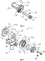
- FIG. 1 a possible embodiment of a joint body 20 is shown, in which a locking element 30 can be inserted.
- the joint body 20 has a joint body surface 21 which, together with a joint receiving surface 11, forms a hinge joint, which is pivotable about an axis of rotation 12. Accordingly, the hinge body surface is formed cylindrically with a circular cross section.
- the joint body surface 21 has a body locking structure 24, which in the in FIG. 1 shown embodiment is provided as a recess which extends into the joint body surface 21. As shown, the recess may extend across the entire width of the articulating body surface 21. However, it is also possible for the recess to extend only partially across the width of the articulated body surface 21.
- this can also be provided on the joint body 20 within the joint body surface 21 or on at least one end face of the joint body 20.
- the joint body 20 has at one end a securing portion 25, which is designed as a flange in the present embodiment. This provides, as already described above, a defined insertion depth of Hinge body 20 in a joint receptacle 10 (see FIG. 2 ) ready.
- locking member 30 allows for indirect locking of the body locking structure 24 and a receiving locking structure 14 of the hinge seat 10 (see FIG. 2 ). It is also possible to provide a direct locking between the body locking structure and the receiving locking structure. In such a case, the body locking structure and the receiving locking structure are complementary to each other, so that no locking member is necessary to cause a lock between the joint body 20 and the hinge seat 10.
- the locking element 30 is in the in FIG. 1 shown embodiment parallel to and at a distance from the axis of rotation 12 in the receptacle of the body locking structure 24 insertable.
- the recess of the body locking structure 24 is made complementary to the shape of the locking element 30. In the exemplary embodiment shown, it has a part-circular cross-section.
- the locking element 30 is inserted from the side into the body locking structure 24, on which the securing portion 25 of the joint body 20 is provided.
- the securing portion 25 designed as a flange has a through hole 27.
- the through-hole 27 is preferably formed with a thread into which a threaded portion 32 of the locking element 30 engages in order to secure the locking element 30 to the joint body 20. This backup prevents unintentional release of the lock.
- the threaded portion 32 preferably has a larger diameter than that of the body locking structure 24 via a form-fitting engageable locking portion 34 of the locking member 30. Furthermore, the locking member 30 at its insertion in the rear end behind the threaded portion 32, a head 33, in which an engagement of a tool, a tool engaging portion 35 is provided to screw the threaded portion 32 in the threaded through hole 27 of the joint body 20.
- the a hinge assembly 1 illustrative FIG. 2 shows that in FIG. 1 described locking element 30 in engagement with the body locking structure 24 of the joint body 20.
- the joint body 20 is inserted into a through hole 13 along the axis of rotation 12 of the joint. At least a part of the inner surface of the through hole 13 forms the hinge receiving surface 11, which is movable relative to the hinge body surface 21 of the joint body 20 in the assembled unlocked state.
- the hinge receiving surface 11 is interrupted by a recess which forms the receiving lock structure 14.
- This recess extends over the entire depth of the through hole 13.
- an embodiment of the recess is possible, which extends over only a part of the depth of the through hole 13.
- such an arrangement of the locking structures 14, 24 has the advantage of a very stable locking with little play.
- the joint receptacle 10 on a connecting portion 16 which, as will be described in more detail below, for making a connection with a second joint component 60 is used (see FIGS. 3 and 4 ).
- a joint recording which is located on the tibial side of a knee joint replacement.
- FIG. 2 two adapter elements 40a, 40b shown, which are arranged on both sides of the through hole 13 of the joint seat 10. As related to the below FIGS. 5 and 6 is described, the adapter elements 40a, 40b are arranged or inserted laterally to the first joint component 50.
- the adapter elements 40a, 40b have detents 42 which prevent rotation about the axis of rotation 12 relative to the first hinge component 50.
- the adapter element 40b has on the side facing the securing portion 25 a stop surface 43 which contacts the securing portion 25 when the joint body 20 is inserted.
- this has a through hole 47 with a locking element recess 45.
- the locking element recess 45 is at least partially designed so that it receives a portion of the threaded portion 32 of the locking member 30, but preferably does not go into this with threaded engagement.
- the locking element recess 45 preferably narrows towards the side of the adapter element 40b opposite the abutment surfaces 43, as in the case of the second adapter element 40a in FIG. 2 recognizable, so that thereafter only the locking portion 34 of the locking element 30 can be inserted. It will be understood that the adapter element 40b may be implemented with a locking element recess 45 which is provided continuously only for receiving the locking section 34.
- a locking element recess 45 is preferably provided on the locking section 34 in the case of both adapter elements 40a, 40b
- embodiments are still conceivable in which only the adapter element 40b located on the side of the securing section 25 has a locking element recess 45.
- the locking section 34 is received in both adapter elements 40a, 40b, a more stable locking is possible because the locking element 30 can be supported on both sides by the joint receptacle 10.
- the adapter element 40b also has in the in FIG. 2 In the embodiment shown in the stop surface 43, a receptacle 46 for a fastening element 26.
- This receptacle 46 is preferably formed as a threaded hole.
- the fastening element 26 is inserted, which via a through hole 22 in the securing portion 25 of the joint body 20, the joint body 20 on the adapter element 40b guaranteed. In this way it can be ensured that in the unlocked state of the joint structure 1, a relative movement only between the joint receiving surface 11 and the joint body surface 21 is possible.
- this may be omitted in alternative embodiments.
- the locking member 30 is inserted into the through hole 27 of the joint body 20, the locking element recess 45 in the adapter member 40b, the receiving latch structure 14 and the locking element recess 45 of the adapter element 40a only when they assume a locking position in which they are aligned.
- the joint body 20 is connected directly to a first joint component 50 instead of the adapter element 40, accordingly at least the receiving locking structure 14 and the body locking structure 24 must be aligned with each other and using a locking element 30 corresponding to the recess in the first recess Joint component 50.
- the angle between the first hinge component 50 and the second hinge component 60 which the hinge assembly 1 provides in the locked state is, depending on the embodiment, a corresponding relative arrangement of the female latch structure 14, the body latch structure 24, the latch recess 45, and / or the detents 42 Rotation axis 12 to each other adjustable.
- an adjustment of this angle is most easily possible by a corresponding arrangement of the detents 42 on the adapter elements 40a and 40b. Consequently, by appropriate placement of the detents 42 on the adapter elements 40a and 40b different adapter elements may be provided for different locking angles.
- two or three receiving locking structures 14 are provided which, as described, are even more preferably designed as a recess in the joint receptacle 11.
- a surgeon may select a first limb-arranged female interlocking structure 14 or a second limb-arranged female interlocking structure 14. It is also conceivable to choose a locking position between an extension and a flexion of the joint, which may be advantageous for walking with a walking aid, for example.
- a centering means 28 can furthermore be provided which, when the locking position is reached, engages noticeably in a centering recess 19 of the joint receptacle 10.
- a centering pin is provided as centering means 28, which can engage in the securing portion 25 of the joint body 20 in a centering recess 19 through a centering through hole 29, which signals to an operator that the locking position has been reached is and thus the locking member 30 can be inserted.
- joint structure 1 In the following, the assembly of the joint structure 1 will now be described in more detail with reference to a knee joint replacement, but it can also be carried out on other joints, such as, for example, an elbow joint.
- second joint component 60 is a tibial component, which can be already implanted in a retrofit of the joint structure 1 in the fall of a retrofit in the knee of a patient or implant as a new implant.
- the connecting section of the joint receptacle 10 is inserted into a corresponding connecting section 62 of the second joint component 60.
- the assembly of the joint receptacle 10 takes place with the second joint component 60 via a positive connection and subsequent fixation with fasteners 18.
- other mounting options of the second joint component 60 with the hinge assembly 10 are conceivable, such as a cone connection.
- first joint component 50 already be implanted, so that a previously existing joint structure is replaced by the joint structure 10, or newly implanted together with the joint structure 10.
- the first joint component 50 shown is a femoral component of a knee joint.
- 10 adapter elements 40a, 40b are used in the context of the joint structure. Consequently, the hinge assembly 10, as described above, is a modular system that makes the hinge assembly of a can replace common Gelenkendoprothese with the locked joint structure 1 of the present invention.
- the adapter elements 40a, 40b are each inserted via an insertion projection 49 into corresponding through holes 59 of the first joint component 50.
- these through holes 59 may be provided for a hinge axis.
- the latches 42 of the adapter elements 40a, 40b are engaged with corresponding latches 52 of the first hinge component 50 upon insertion of the adapter elements 40a, 40b.
- each adapter element 40 has two detents 42 which cooperate with two detents 52 of the first hinge component to fix the respective adapter element 40 in the corresponding through hole 59 in the rotational direction.
- the locking position and thus the angle between the first joint component 50 and the second joint component can be determined by the choice of the adapter elements 40 by the latches are provided according to the circumference of the adapter elements.
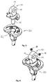
- FIGS. 5 and 6 It can be seen from the locking element recess 45 and the receiving locking structure 14 positioned by the detents 42 and 52 that the exemplary knee joint replacement is in extension in the locked state. However, as discussed above, it may be advantageous to choose a different angle, such as an angle at which the patient can assume a sitting position.
- FIG. 6 shows the pre-assembled with the adapter elements 40a, 40b first joint component 50 and pre-assembled with the joint receiving 10 second joint component 60 prior to their positioning to each other.
- the first joint component 50 may have, in addition to the joint formed by the joint structure 1, a further joint surface 55 which, in the assembled state of the joint, interacts with a joint surface 65 mounted on the second joint component.
- first joint component 50 and the second joint component 60 are arranged relative to one another such that the through-hole 47 of the adapter elements 40a and 40b and the through-hole 13 of the joint receptacle 10 are aligned with one another.
- the hinge body 20 can be inserted via the through hole 47 of the first adapter member 40b, the through hole 13 of the hinge receiver 10, and the through hole 47 of the second adapter member 40a.
- first joint component 50 when the first joint component 50 is an already implanted joint component, bone tissue may be located in front of the through holes 59 of the first joint component 50. Accordingly, a passage to at least one of the through holes 59 must first be created intraoperatively. This is preferably done with a hollow milling machine, with which a bone cylinder with a diameter is taken laterally along the axis of rotation 12 of the joint, so that a free access to the at least one through hole 59 of the first joint component 50 is formed. After assembly, the removed bone cylinder can be used again to re-close the access to the respective through hole 59 created.
- the securing of the joint body takes place via a single securing section 25 designed as a flange. Consequently, access to one of the through-holes 59 is sufficient to retrofit the joint replacement with the joint structure 1. This has the advantage that the bone tissue and thus the patient are spared.
- FIG. 7 it can be seen that the joint body 20 can be used with already engaged locking element 30. It is understood that this is not necessary, but instead the locking element 30 is only used when a locking of the joint is desired or for a locking first the joint body 20 and then the locking member 30 is used.
- the hinge body 20 and the locking member 30 are used in this way, must in the embodiment shown in addition to the aforementioned through holes 47 and 13, the locking element recess 45 of at least one of the adapter elements 40a, 40b and the recess designed as a receiving locking structure 14 are aligned, ie are in the locked position.
- FIG. 8 Finally, Figure 1 shows the joint assembly 1 in a state mounted with the first joint component 50 and the second joint component 60. As can be seen, the hinge body 20 is secured to the first hinge component 50 via the securing portion 25 and the fastener 26. Consequently, in the embodiment shown in the joint structure 1, only a relative movement between the joint receiving surface 11 and the joint body surface 21 is possible.
- centering means can be removed.
- the centering means as described above as an aid to find the locking position, but instead to use it as additional securing elements against rotation of the joint body 20 relative to the first joint component 50.
Landscapes
- Health & Medical Sciences (AREA)
- Orthopedic Medicine & Surgery (AREA)
- Physical Education & Sports Medicine (AREA)
- Cardiology (AREA)
- Oral & Maxillofacial Surgery (AREA)
- Transplantation (AREA)
- Engineering & Computer Science (AREA)
- Biomedical Technology (AREA)
- Heart & Thoracic Surgery (AREA)
- Vascular Medicine (AREA)
- Life Sciences & Earth Sciences (AREA)
- Animal Behavior & Ethology (AREA)
- General Health & Medical Sciences (AREA)
- Public Health (AREA)
- Veterinary Medicine (AREA)
- Prostheses (AREA)
- Bridges Or Land Bridges (AREA)
Priority Applications (7)
| Application Number | Priority Date | Filing Date | Title |
|---|---|---|---|
| EP16159418.9A EP3216425B1 (fr) | 2016-03-09 | 2016-03-09 | Articulation |
| ES16159418T ES2773660T3 (es) | 2016-03-09 | 2016-03-09 | Estructura articulada |
| AU2017229259A AU2017229259B2 (en) | 2016-03-09 | 2017-03-06 | Joint configuration |
| RU2018135294A RU2721591C2 (ru) | 2016-03-09 | 2017-03-06 | Соединительная структура |
| CN201780015813.XA CN108778192B (zh) | 2016-03-09 | 2017-03-06 | 关节结构 |
| US16/082,954 US10973643B2 (en) | 2016-03-09 | 2017-03-06 | Joint configuration |
| PCT/EP2017/055165 WO2017153322A1 (fr) | 2016-03-09 | 2017-03-06 | Ensemble articulaire |
Applications Claiming Priority (1)
| Application Number | Priority Date | Filing Date | Title |
|---|---|---|---|
| EP16159418.9A EP3216425B1 (fr) | 2016-03-09 | 2016-03-09 | Articulation |
Publications (2)
| Publication Number | Publication Date |
|---|---|
| EP3216425A1 true EP3216425A1 (fr) | 2017-09-13 |
| EP3216425B1 EP3216425B1 (fr) | 2019-12-25 |
Family
ID=55527344
Family Applications (1)
| Application Number | Title | Priority Date | Filing Date |
|---|---|---|---|
| EP16159418.9A Active EP3216425B1 (fr) | 2016-03-09 | 2016-03-09 | Articulation |
Country Status (7)
| Country | Link |
|---|---|
| US (1) | US10973643B2 (fr) |
| EP (1) | EP3216425B1 (fr) |
| CN (1) | CN108778192B (fr) |
| AU (1) | AU2017229259B2 (fr) |
| ES (1) | ES2773660T3 (fr) |
| RU (1) | RU2721591C2 (fr) |
| WO (1) | WO2017153322A1 (fr) |
Cited By (1)
| Publication number | Priority date | Publication date | Assignee | Title |
|---|---|---|---|---|
| EP3763335A1 (fr) * | 2019-07-11 | 2021-01-13 | Waldemar Link GmbH & Co. KG | Implant articulaire pour une administration d'un médicament |
Citations (4)
| Publication number | Priority date | Publication date | Assignee | Title |
|---|---|---|---|---|
| WO2006087582A1 (fr) * | 2005-02-21 | 2006-08-24 | Ardemed Innovations Limited | Dispositifs d'articulation |
| FR2935894A1 (fr) * | 2008-09-15 | 2010-03-19 | C2F Implants | Prothese d'articulation du genou, du type dit a "charniere". |
| WO2013144392A1 (fr) * | 2012-03-29 | 2013-10-03 | Universidad De Málaga | Prothèse de genou à mobilité réglable |
| US20140025172A1 (en) * | 2012-07-17 | 2014-01-23 | Kim John Chillag | Lockable implants and related methods |
Family Cites Families (10)
| Publication number | Priority date | Publication date | Assignee | Title |
|---|---|---|---|---|
| ES2120367B1 (es) * | 1996-06-13 | 1999-05-16 | Levante Ind Quirurgicas | Rodilla de tumoracion. |
| RU37931U1 (ru) | 2003-12-01 | 2004-05-20 | Общество с ограниченной ответственностью Нейроортопедический центр "ОртоС" | Модуль коленный (варианты) |
| RU51490U1 (ru) | 2004-07-12 | 2006-02-27 | Валерий Михайлович Попков | Эндопротез локтевого сустава |
| ES2385896T3 (es) * | 2005-05-09 | 2012-08-02 | Aesculap Ag | Endoprótesis de rodilla acoplada |
| RU60344U1 (ru) | 2006-08-14 | 2007-01-27 | Общество с ограниченной ответственностью Нейроортопедический центр "ОртоС" | Модуль коленный |
| US8328873B2 (en) * | 2007-01-10 | 2012-12-11 | Biomet Manufacturing Corp. | Knee joint prosthesis system and method for implantation |
| RU2380061C1 (ru) | 2008-08-04 | 2010-01-27 | Общество с ограниченной ответственностью Нейроортопедический центр "ОртоС" | Модуль коленный |
| RU2433803C1 (ru) | 2010-04-28 | 2011-11-20 | Общество с ограниченной ответственностью "ИЛЬКОМ" | Модульный эндопротез коленного сустава |
| US8795387B1 (en) * | 2012-02-16 | 2014-08-05 | Matthew William Razink | Prosthetic wrist |
| DE102015102391B3 (de) * | 2015-02-19 | 2016-06-23 | Implantcast Gmbh | Endoprothese für die Kniegelenkarthrodese |
-
2016
- 2016-03-09 EP EP16159418.9A patent/EP3216425B1/fr active Active
- 2016-03-09 ES ES16159418T patent/ES2773660T3/es active Active
-
2017
- 2017-03-06 AU AU2017229259A patent/AU2017229259B2/en not_active Ceased
- 2017-03-06 US US16/082,954 patent/US10973643B2/en active Active
- 2017-03-06 WO PCT/EP2017/055165 patent/WO2017153322A1/fr active Application Filing
- 2017-03-06 RU RU2018135294A patent/RU2721591C2/ru active
- 2017-03-06 CN CN201780015813.XA patent/CN108778192B/zh not_active Expired - Fee Related
Patent Citations (4)
| Publication number | Priority date | Publication date | Assignee | Title |
|---|---|---|---|---|
| WO2006087582A1 (fr) * | 2005-02-21 | 2006-08-24 | Ardemed Innovations Limited | Dispositifs d'articulation |
| FR2935894A1 (fr) * | 2008-09-15 | 2010-03-19 | C2F Implants | Prothese d'articulation du genou, du type dit a "charniere". |
| WO2013144392A1 (fr) * | 2012-03-29 | 2013-10-03 | Universidad De Málaga | Prothèse de genou à mobilité réglable |
| US20140025172A1 (en) * | 2012-07-17 | 2014-01-23 | Kim John Chillag | Lockable implants and related methods |
Cited By (2)
| Publication number | Priority date | Publication date | Assignee | Title |
|---|---|---|---|---|
| EP3763335A1 (fr) * | 2019-07-11 | 2021-01-13 | Waldemar Link GmbH & Co. KG | Implant articulaire pour une administration d'un médicament |
| WO2021005152A1 (fr) * | 2019-07-11 | 2021-01-14 | Waldemar Link Gmbh & Co. Kg | Implant articulaire conçu pour administrer un médicament |
Also Published As
| Publication number | Publication date |
|---|---|
| WO2017153322A1 (fr) | 2017-09-14 |
| ES2773660T3 (es) | 2020-07-14 |
| CN108778192B (zh) | 2021-08-03 |
| EP3216425B1 (fr) | 2019-12-25 |
| AU2017229259B2 (en) | 2021-04-01 |
| RU2018135294A (ru) | 2020-04-09 |
| CN108778192A (zh) | 2018-11-09 |
| RU2018135294A3 (fr) | 2020-04-09 |
| AU2017229259A1 (en) | 2018-10-18 |
| RU2721591C2 (ru) | 2020-05-20 |
| US20190099275A1 (en) | 2019-04-04 |
| US10973643B2 (en) | 2021-04-13 |
Similar Documents
| Publication | Publication Date | Title |
|---|---|---|
| EP0791342B1 (fr) | Endoprothèse du col du fémur pour une articulation de hanche artificielle | |
| EP0079441B1 (fr) | Endoprothèse pour remplacer les os en forme de bâton | |
| DE60224470T2 (de) | Hüftimplantataufbau | |
| EP1959871B1 (fr) | Prothese d'articulation a facettes | |
| DE60313902T2 (de) | Anpassbare Prothese für lange Knochen | |
| DE3917916C1 (fr) | ||
| DE69934639T2 (de) | In einem Gehäuse mit Innengewinde befestigter femoraler Schaft für eine modulare Knieprothese | |
| DE69934060T2 (de) | Femoraler Schaftbausatz für eine modulare Knieprothese | |
| EP0791344B1 (fr) | Endoprothese de l'articulation du genou | |
| DE69934055T2 (de) | Femurteil einer modularen Knieprothese | |
| DE102008045291B4 (de) | Kniearthrodese-Implantat | |
| DE2323456A1 (de) | Kuenstliches hueftgelenk | |
| EP2394606A1 (fr) | Prothèse pour le remplacement partiel d'un os long | |
| DE19841688A1 (de) | Hohle verschließbare Vorrichtung für das zeitweilige oder endgültige chirurgische Anbringen in einem Knochen, um einen Durchgang zum Innenraum eines Hohlraumes oder zu einem innenliegenden anatomischen Ort von Säugetieren zur Verfügung zu stellen | |
| EP0622056A2 (fr) | Organe d'ancrage implantable pour la réception de prothèses et d'objets similaires | |
| WO2005037117A1 (fr) | Systeme pour le traitement a effraction minimale d'une fracture d'un os, notamment d'une fracture proximale de l'humerus ou du femur | |
| DE4442204A1 (de) | Modulare Gelenkprothese | |
| DE4442206A1 (de) | Gelenkprothese | |
| EP0290735A1 (fr) | Kit pour le montage d'une prothèse de tête de fémur | |
| DE102016105230A1 (de) | Stabilisierungsstruktur zur Stabilisierung oder fixierung von Sternoclavikulargelenken | |
| EP2066265B1 (fr) | Implant de hanche | |
| EP3216425B1 (fr) | Articulation | |
| EP3763335A1 (fr) | Implant articulaire pour une administration d'un médicament | |
| AT502137B1 (de) | Primärschaft für eine hüftgelenksprothese | |
| DE102005015598B4 (de) | Kniegelenkendoprothese und Protheseset mit einer derartigen Kniegelenkendoprothese |
Legal Events
| Date | Code | Title | Description |
|---|---|---|---|
| PUAI | Public reference made under article 153(3) epc to a published international application that has entered the european phase |
Free format text: ORIGINAL CODE: 0009012 |
|
| STAA | Information on the status of an ep patent application or granted ep patent |
Free format text: STATUS: THE APPLICATION HAS BEEN PUBLISHED |
|
| AK | Designated contracting states |
Kind code of ref document: A1 Designated state(s): AL AT BE BG CH CY CZ DE DK EE ES FI FR GB GR HR HU IE IS IT LI LT LU LV MC MK MT NL NO PL PT RO RS SE SI SK SM TR |
|
| AX | Request for extension of the european patent |
Extension state: BA ME |
|
| STAA | Information on the status of an ep patent application or granted ep patent |
Free format text: STATUS: REQUEST FOR EXAMINATION WAS MADE |
|
| 17P | Request for examination filed |
Effective date: 20170926 |
|
| RBV | Designated contracting states (corrected) |
Designated state(s): AL AT BE BG CH CY CZ DE DK EE ES FI FR GB GR HR HU IE IS IT LI LT LU LV MC MK MT NL NO PL PT RO RS SE SI SK SM TR |
|
| STAA | Information on the status of an ep patent application or granted ep patent |
Free format text: STATUS: EXAMINATION IS IN PROGRESS |
|
| 17Q | First examination report despatched |
Effective date: 20181218 |
|
| RIC1 | Information provided on ipc code assigned before grant |
Ipc: A61F 2/38 20060101AFI20190702BHEP Ipc: A61F 2/30 20060101ALN20190702BHEP |
|
| GRAP | Despatch of communication of intention to grant a patent |
Free format text: ORIGINAL CODE: EPIDOSNIGR1 |
|
| STAA | Information on the status of an ep patent application or granted ep patent |
Free format text: STATUS: GRANT OF PATENT IS INTENDED |
|
| INTG | Intention to grant announced |
Effective date: 20190823 |
|
| RIC1 | Information provided on ipc code assigned before grant |
Ipc: A61F 2/38 20060101AFI20190812BHEP Ipc: A61F 2/30 20060101ALN20190812BHEP |
|
| RIN1 | Information on inventor provided before grant (corrected) |
Inventor name: DAENIKE, ANDREAS Inventor name: BORCHERS, UDO Inventor name: JENDRO, GUENTHER Inventor name: EWALD, JOERG Inventor name: LINK, HELMUT D. |
|
| GRAS | Grant fee paid |
Free format text: ORIGINAL CODE: EPIDOSNIGR3 |
|
| GRAA | (expected) grant |
Free format text: ORIGINAL CODE: 0009210 |
|
| STAA | Information on the status of an ep patent application or granted ep patent |
Free format text: STATUS: THE PATENT HAS BEEN GRANTED |
|
| AK | Designated contracting states |
Kind code of ref document: B1 Designated state(s): AL AT BE BG CH CY CZ DE DK EE ES FI FR GB GR HR HU IE IS IT LI LT LU LV MC MK MT NL NO PL PT RO RS SE SI SK SM TR |
|
| REG | Reference to a national code |
Ref country code: GB Ref legal event code: FG4D Free format text: NOT ENGLISH |
|
| REG | Reference to a national code |
Ref country code: CH Ref legal event code: EP |
|
| REG | Reference to a national code |
Ref country code: AT Ref legal event code: REF Ref document number: 1216312 Country of ref document: AT Kind code of ref document: T Effective date: 20200115 |
|
| REG | Reference to a national code |
Ref country code: DE Ref legal event code: R096 Ref document number: 502016008109 Country of ref document: DE |
|
| REG | Reference to a national code |
Ref country code: IE Ref legal event code: FG4D Free format text: LANGUAGE OF EP DOCUMENT: GERMAN |
|
| REG | Reference to a national code |
Ref country code: SE Ref legal event code: TRGR |
|
| REG | Reference to a national code |
Ref country code: NL Ref legal event code: MP Effective date: 20191225 |
|
| PG25 | Lapsed in a contracting state [announced via postgrant information from national office to epo] |
Ref country code: FI Free format text: LAPSE BECAUSE OF FAILURE TO SUBMIT A TRANSLATION OF THE DESCRIPTION OR TO PAY THE FEE WITHIN THE PRESCRIBED TIME-LIMIT Effective date: 20191225 Ref country code: NO Free format text: LAPSE BECAUSE OF FAILURE TO SUBMIT A TRANSLATION OF THE DESCRIPTION OR TO PAY THE FEE WITHIN THE PRESCRIBED TIME-LIMIT Effective date: 20200325 Ref country code: GR Free format text: LAPSE BECAUSE OF FAILURE TO SUBMIT A TRANSLATION OF THE DESCRIPTION OR TO PAY THE FEE WITHIN THE PRESCRIBED TIME-LIMIT Effective date: 20200326 Ref country code: LT Free format text: LAPSE BECAUSE OF FAILURE TO SUBMIT A TRANSLATION OF THE DESCRIPTION OR TO PAY THE FEE WITHIN THE PRESCRIBED TIME-LIMIT Effective date: 20191225 Ref country code: LV Free format text: LAPSE BECAUSE OF FAILURE TO SUBMIT A TRANSLATION OF THE DESCRIPTION OR TO PAY THE FEE WITHIN THE PRESCRIBED TIME-LIMIT Effective date: 20191225 Ref country code: BG Free format text: LAPSE BECAUSE OF FAILURE TO SUBMIT A TRANSLATION OF THE DESCRIPTION OR TO PAY THE FEE WITHIN THE PRESCRIBED TIME-LIMIT Effective date: 20200325 |
|
| REG | Reference to a national code |
Ref country code: LT Ref legal event code: MG4D |
|
| PG25 | Lapsed in a contracting state [announced via postgrant information from national office to epo] |
Ref country code: RS Free format text: LAPSE BECAUSE OF FAILURE TO SUBMIT A TRANSLATION OF THE DESCRIPTION OR TO PAY THE FEE WITHIN THE PRESCRIBED TIME-LIMIT Effective date: 20191225 Ref country code: HR Free format text: LAPSE BECAUSE OF FAILURE TO SUBMIT A TRANSLATION OF THE DESCRIPTION OR TO PAY THE FEE WITHIN THE PRESCRIBED TIME-LIMIT Effective date: 20191225 |
|
| PG25 | Lapsed in a contracting state [announced via postgrant information from national office to epo] |
Ref country code: AL Free format text: LAPSE BECAUSE OF FAILURE TO SUBMIT A TRANSLATION OF THE DESCRIPTION OR TO PAY THE FEE WITHIN THE PRESCRIBED TIME-LIMIT Effective date: 20191225 |
|
| REG | Reference to a national code |
Ref country code: ES Ref legal event code: FG2A Ref document number: 2773660 Country of ref document: ES Kind code of ref document: T3 Effective date: 20200714 |
|
| PG25 | Lapsed in a contracting state [announced via postgrant information from national office to epo] |
Ref country code: RO Free format text: LAPSE BECAUSE OF FAILURE TO SUBMIT A TRANSLATION OF THE DESCRIPTION OR TO PAY THE FEE WITHIN THE PRESCRIBED TIME-LIMIT Effective date: 20191225 Ref country code: PT Free format text: LAPSE BECAUSE OF FAILURE TO SUBMIT A TRANSLATION OF THE DESCRIPTION OR TO PAY THE FEE WITHIN THE PRESCRIBED TIME-LIMIT Effective date: 20200520 Ref country code: EE Free format text: LAPSE BECAUSE OF FAILURE TO SUBMIT A TRANSLATION OF THE DESCRIPTION OR TO PAY THE FEE WITHIN THE PRESCRIBED TIME-LIMIT Effective date: 20191225 Ref country code: CZ Free format text: LAPSE BECAUSE OF FAILURE TO SUBMIT A TRANSLATION OF THE DESCRIPTION OR TO PAY THE FEE WITHIN THE PRESCRIBED TIME-LIMIT Effective date: 20191225 Ref country code: NL Free format text: LAPSE BECAUSE OF FAILURE TO SUBMIT A TRANSLATION OF THE DESCRIPTION OR TO PAY THE FEE WITHIN THE PRESCRIBED TIME-LIMIT Effective date: 20191225 |
|
| PG25 | Lapsed in a contracting state [announced via postgrant information from national office to epo] |
Ref country code: SK Free format text: LAPSE BECAUSE OF FAILURE TO SUBMIT A TRANSLATION OF THE DESCRIPTION OR TO PAY THE FEE WITHIN THE PRESCRIBED TIME-LIMIT Effective date: 20191225 Ref country code: IS Free format text: LAPSE BECAUSE OF FAILURE TO SUBMIT A TRANSLATION OF THE DESCRIPTION OR TO PAY THE FEE WITHIN THE PRESCRIBED TIME-LIMIT Effective date: 20200425 Ref country code: SM Free format text: LAPSE BECAUSE OF FAILURE TO SUBMIT A TRANSLATION OF THE DESCRIPTION OR TO PAY THE FEE WITHIN THE PRESCRIBED TIME-LIMIT Effective date: 20191225 |
|
| REG | Reference to a national code |
Ref country code: DE Ref legal event code: R097 Ref document number: 502016008109 Country of ref document: DE |
|
| PG25 | Lapsed in a contracting state [announced via postgrant information from national office to epo] |
Ref country code: MC Free format text: LAPSE BECAUSE OF FAILURE TO SUBMIT A TRANSLATION OF THE DESCRIPTION OR TO PAY THE FEE WITHIN THE PRESCRIBED TIME-LIMIT Effective date: 20191225 Ref country code: DK Free format text: LAPSE BECAUSE OF FAILURE TO SUBMIT A TRANSLATION OF THE DESCRIPTION OR TO PAY THE FEE WITHIN THE PRESCRIBED TIME-LIMIT Effective date: 20191225 |
|
| PLBE | No opposition filed within time limit |
Free format text: ORIGINAL CODE: 0009261 |
|
| STAA | Information on the status of an ep patent application or granted ep patent |
Free format text: STATUS: NO OPPOSITION FILED WITHIN TIME LIMIT |
|
| PG25 | Lapsed in a contracting state [announced via postgrant information from national office to epo] |
Ref country code: SI Free format text: LAPSE BECAUSE OF FAILURE TO SUBMIT A TRANSLATION OF THE DESCRIPTION OR TO PAY THE FEE WITHIN THE PRESCRIBED TIME-LIMIT Effective date: 20191225 |
|
| 26N | No opposition filed |
Effective date: 20200928 |
|
| REG | Reference to a national code |
Ref country code: BE Ref legal event code: MM Effective date: 20200331 |
|
| PG25 | Lapsed in a contracting state [announced via postgrant information from national office to epo] |
Ref country code: LU Free format text: LAPSE BECAUSE OF NON-PAYMENT OF DUE FEES Effective date: 20200309 |
|
| PG25 | Lapsed in a contracting state [announced via postgrant information from national office to epo] |
Ref country code: BE Free format text: LAPSE BECAUSE OF NON-PAYMENT OF DUE FEES Effective date: 20200331 Ref country code: PL Free format text: LAPSE BECAUSE OF FAILURE TO SUBMIT A TRANSLATION OF THE DESCRIPTION OR TO PAY THE FEE WITHIN THE PRESCRIBED TIME-LIMIT Effective date: 20191225 |
|
| PGFP | Annual fee paid to national office [announced via postgrant information from national office to epo] |
Ref country code: IE Payment date: 20210322 Year of fee payment: 6 |
|
| PGFP | Annual fee paid to national office [announced via postgrant information from national office to epo] |
Ref country code: TR Payment date: 20210301 Year of fee payment: 6 |
|
| PGFP | Annual fee paid to national office [announced via postgrant information from national office to epo] |
Ref country code: CH Payment date: 20220324 Year of fee payment: 7 |
|
| REG | Reference to a national code |
Ref country code: AT Ref legal event code: MM01 Ref document number: 1216312 Country of ref document: AT Kind code of ref document: T Effective date: 20210309 |
|
| PG25 | Lapsed in a contracting state [announced via postgrant information from national office to epo] |
Ref country code: MT Free format text: LAPSE BECAUSE OF FAILURE TO SUBMIT A TRANSLATION OF THE DESCRIPTION OR TO PAY THE FEE WITHIN THE PRESCRIBED TIME-LIMIT Effective date: 20191225 Ref country code: CY Free format text: LAPSE BECAUSE OF FAILURE TO SUBMIT A TRANSLATION OF THE DESCRIPTION OR TO PAY THE FEE WITHIN THE PRESCRIBED TIME-LIMIT Effective date: 20191225 |
|
| PG25 | Lapsed in a contracting state [announced via postgrant information from national office to epo] |
Ref country code: MK Free format text: LAPSE BECAUSE OF FAILURE TO SUBMIT A TRANSLATION OF THE DESCRIPTION OR TO PAY THE FEE WITHIN THE PRESCRIBED TIME-LIMIT Effective date: 20191225 |
|
| PG25 | Lapsed in a contracting state [announced via postgrant information from national office to epo] |
Ref country code: AT Free format text: LAPSE BECAUSE OF NON-PAYMENT OF DUE FEES Effective date: 20210309 |
|
| PG25 | Lapsed in a contracting state [announced via postgrant information from national office to epo] |
Ref country code: IE Free format text: LAPSE BECAUSE OF NON-PAYMENT OF DUE FEES Effective date: 20220309 |
|
| PGFP | Annual fee paid to national office [announced via postgrant information from national office to epo] |
Ref country code: FR Payment date: 20230320 Year of fee payment: 8 |
|
| PGFP | Annual fee paid to national office [announced via postgrant information from national office to epo] |
Ref country code: SE Payment date: 20230315 Year of fee payment: 8 |
|
| P01 | Opt-out of the competence of the unified patent court (upc) registered |
Effective date: 20230518 |
|
| PGFP | Annual fee paid to national office [announced via postgrant information from national office to epo] |
Ref country code: IT Payment date: 20230331 Year of fee payment: 8 Ref country code: ES Payment date: 20230414 Year of fee payment: 8 |
|
| REG | Reference to a national code |
Ref country code: CH Ref legal event code: PL |
|
| PG25 | Lapsed in a contracting state [announced via postgrant information from national office to epo] |
Ref country code: LI Free format text: LAPSE BECAUSE OF NON-PAYMENT OF DUE FEES Effective date: 20230331 Ref country code: CH Free format text: LAPSE BECAUSE OF NON-PAYMENT OF DUE FEES Effective date: 20230331 |
|
| PGFP | Annual fee paid to national office [announced via postgrant information from national office to epo] |
Ref country code: DE Payment date: 20240321 Year of fee payment: 9 Ref country code: GB Payment date: 20240322 Year of fee payment: 9 |