EP3215832B1 - Verfahren und vorrichtung zur überwachung und diagnose elektrochemischer geräte basierend auf einer automatischen erkennung der elektrochemischen impedanz - Google Patents
Verfahren und vorrichtung zur überwachung und diagnose elektrochemischer geräte basierend auf einer automatischen erkennung der elektrochemischen impedanz Download PDFInfo
- Publication number
- EP3215832B1 EP3215832B1 EP15805259.7A EP15805259A EP3215832B1 EP 3215832 B1 EP3215832 B1 EP 3215832B1 EP 15805259 A EP15805259 A EP 15805259A EP 3215832 B1 EP3215832 B1 EP 3215832B1
- Authority
- EP
- European Patent Office
- Prior art keywords
- parameters
- spectrum
- arc
- ecm
- point
- Prior art date
- Legal status (The legal status is an assumption and is not a legal conclusion. Google has not performed a legal analysis and makes no representation as to the accuracy of the status listed.)
- Active
Links
- 238000000034 method Methods 0.000 title claims description 72
- 238000012544 monitoring process Methods 0.000 title description 7
- 238000001228 spectrum Methods 0.000 claims description 42
- 238000012546 transfer Methods 0.000 claims description 38
- 238000000157 electrochemical-induced impedance spectroscopy Methods 0.000 claims description 34
- 239000000446 fuel Substances 0.000 claims description 31
- 238000009792 diffusion process Methods 0.000 claims description 30
- 238000001453 impedance spectrum Methods 0.000 claims description 29
- 239000011159 matrix material Substances 0.000 claims description 20
- 238000004458 analytical method Methods 0.000 claims description 11
- 208000024891 symptom Diseases 0.000 claims description 10
- 239000003990 capacitor Substances 0.000 claims description 9
- 238000005457 optimization Methods 0.000 claims description 5
- 238000005070 sampling Methods 0.000 claims description 5
- 229910052739 hydrogen Inorganic materials 0.000 claims description 3
- 239000005518 polymer electrolyte Substances 0.000 claims description 3
- 238000012545 processing Methods 0.000 claims description 3
- 238000001914 filtration Methods 0.000 claims description 2
- 230000000875 corresponding effect Effects 0.000 description 19
- 238000005259 measurement Methods 0.000 description 14
- 238000003745 diagnosis Methods 0.000 description 9
- 238000010586 diagram Methods 0.000 description 8
- 238000011156 evaluation Methods 0.000 description 7
- 239000003792 electrolyte Substances 0.000 description 3
- 238000005516 engineering process Methods 0.000 description 3
- 230000036571 hydration Effects 0.000 description 3
- 238000006703 hydration reaction Methods 0.000 description 3
- 239000012528 membrane Substances 0.000 description 3
- 238000012986 modification Methods 0.000 description 3
- 230000004048 modification Effects 0.000 description 3
- UFHFLCQGNIYNRP-UHFFFAOYSA-N Hydrogen Chemical compound [H][H] UFHFLCQGNIYNRP-UHFFFAOYSA-N 0.000 description 2
- 230000008859 change Effects 0.000 description 2
- 230000001276 controlling effect Effects 0.000 description 2
- 230000006866 deterioration Effects 0.000 description 2
- 238000009826 distribution Methods 0.000 description 2
- 230000000694 effects Effects 0.000 description 2
- 230000014509 gene expression Effects 0.000 description 2
- 230000036541 health Effects 0.000 description 2
- 239000001257 hydrogen Substances 0.000 description 2
- 230000002159 abnormal effect Effects 0.000 description 1
- 230000005856 abnormality Effects 0.000 description 1
- 238000013459 approach Methods 0.000 description 1
- 230000015556 catabolic process Effects 0.000 description 1
- 238000004891 communication Methods 0.000 description 1
- 230000002596 correlated effect Effects 0.000 description 1
- 238000006731 degradation reaction Methods 0.000 description 1
- 238000001514 detection method Methods 0.000 description 1
- 238000012774 diagnostic algorithm Methods 0.000 description 1
- 238000002405 diagnostic procedure Methods 0.000 description 1
- 230000005611 electricity Effects 0.000 description 1
- 239000002737 fuel gas Substances 0.000 description 1
- 239000007789 gas Substances 0.000 description 1
- 238000002847 impedance measurement Methods 0.000 description 1
- 230000001788 irregular Effects 0.000 description 1
- 230000007257 malfunction Effects 0.000 description 1
- 238000004519 manufacturing process Methods 0.000 description 1
- 239000011148 porous material Substances 0.000 description 1
- 230000009467 reduction Effects 0.000 description 1
- 238000012552 review Methods 0.000 description 1
- 230000003595 spectral effect Effects 0.000 description 1
- XLYOFNOQVPJJNP-UHFFFAOYSA-N water Substances O XLYOFNOQVPJJNP-UHFFFAOYSA-N 0.000 description 1
- 238000009736 wetting Methods 0.000 description 1
Images


Classifications
-
- G—PHYSICS
- G01—MEASURING; TESTING
- G01N—INVESTIGATING OR ANALYSING MATERIALS BY DETERMINING THEIR CHEMICAL OR PHYSICAL PROPERTIES
- G01N27/00—Investigating or analysing materials by the use of electric, electrochemical, or magnetic means
- G01N27/02—Investigating or analysing materials by the use of electric, electrochemical, or magnetic means by investigating impedance
- G01N27/026—Dielectric impedance spectroscopy
-
- G—PHYSICS
- G01—MEASURING; TESTING
- G01R—MEASURING ELECTRIC VARIABLES; MEASURING MAGNETIC VARIABLES
- G01R31/00—Arrangements for testing electric properties; Arrangements for locating electric faults; Arrangements for electrical testing characterised by what is being tested not provided for elsewhere
- G01R31/36—Arrangements for testing, measuring or monitoring the electrical condition of accumulators or electric batteries, e.g. capacity or state of charge [SoC]
- G01R31/367—Software therefor, e.g. for battery testing using modelling or look-up tables
-
- G—PHYSICS
- G01—MEASURING; TESTING
- G01R—MEASURING ELECTRIC VARIABLES; MEASURING MAGNETIC VARIABLES
- G01R31/00—Arrangements for testing electric properties; Arrangements for locating electric faults; Arrangements for electrical testing characterised by what is being tested not provided for elsewhere
- G01R31/36—Arrangements for testing, measuring or monitoring the electrical condition of accumulators or electric batteries, e.g. capacity or state of charge [SoC]
- G01R31/389—Measuring internal impedance, internal conductance or related variables
-
- H—ELECTRICITY
- H01—ELECTRIC ELEMENTS
- H01M—PROCESSES OR MEANS, e.g. BATTERIES, FOR THE DIRECT CONVERSION OF CHEMICAL ENERGY INTO ELECTRICAL ENERGY
- H01M10/00—Secondary cells; Manufacture thereof
- H01M10/42—Methods or arrangements for servicing or maintenance of secondary cells or secondary half-cells
-
- H—ELECTRICITY
- H01—ELECTRIC ELEMENTS
- H01M—PROCESSES OR MEANS, e.g. BATTERIES, FOR THE DIRECT CONVERSION OF CHEMICAL ENERGY INTO ELECTRICAL ENERGY
- H01M8/00—Fuel cells; Manufacture thereof
- H01M8/04—Auxiliary arrangements, e.g. for control of pressure or for circulation of fluids
- H01M8/04298—Processes for controlling fuel cells or fuel cell systems
- H01M8/04313—Processes for controlling fuel cells or fuel cell systems characterised by the detection or assessment of variables; characterised by the detection or assessment of failure or abnormal function
- H01M8/04664—Failure or abnormal function
-
- H—ELECTRICITY
- H01—ELECTRIC ELEMENTS
- H01M—PROCESSES OR MEANS, e.g. BATTERIES, FOR THE DIRECT CONVERSION OF CHEMICAL ENERGY INTO ELECTRICAL ENERGY
- H01M10/00—Secondary cells; Manufacture thereof
- H01M10/42—Methods or arrangements for servicing or maintenance of secondary cells or secondary half-cells
- H01M10/425—Structural combination with electronic components, e.g. electronic circuits integrated to the outside of the casing
- H01M2010/4271—Battery management systems including electronic circuits, e.g. control of current or voltage to keep battery in healthy state, cell balancing
-
- Y—GENERAL TAGGING OF NEW TECHNOLOGICAL DEVELOPMENTS; GENERAL TAGGING OF CROSS-SECTIONAL TECHNOLOGIES SPANNING OVER SEVERAL SECTIONS OF THE IPC; TECHNICAL SUBJECTS COVERED BY FORMER USPC CROSS-REFERENCE ART COLLECTIONS [XRACs] AND DIGESTS
- Y02—TECHNOLOGIES OR APPLICATIONS FOR MITIGATION OR ADAPTATION AGAINST CLIMATE CHANGE
- Y02E—REDUCTION OF GREENHOUSE GAS [GHG] EMISSIONS, RELATED TO ENERGY GENERATION, TRANSMISSION OR DISTRIBUTION
- Y02E60/00—Enabling technologies; Technologies with a potential or indirect contribution to GHG emissions mitigation
- Y02E60/10—Energy storage using batteries
-
- Y—GENERAL TAGGING OF NEW TECHNOLOGICAL DEVELOPMENTS; GENERAL TAGGING OF CROSS-SECTIONAL TECHNOLOGIES SPANNING OVER SEVERAL SECTIONS OF THE IPC; TECHNICAL SUBJECTS COVERED BY FORMER USPC CROSS-REFERENCE ART COLLECTIONS [XRACs] AND DIGESTS
- Y02—TECHNOLOGIES OR APPLICATIONS FOR MITIGATION OR ADAPTATION AGAINST CLIMATE CHANGE
- Y02E—REDUCTION OF GREENHOUSE GAS [GHG] EMISSIONS, RELATED TO ENERGY GENERATION, TRANSMISSION OR DISTRIBUTION
- Y02E60/00—Enabling technologies; Technologies with a potential or indirect contribution to GHG emissions mitigation
- Y02E60/30—Hydrogen technology
- Y02E60/50—Fuel cells
Definitions
- the present invention relates to a method for monitoring and diagnosis of electrochemical devices to determine their operative state. Such a method is based on an automatic electrochemical impedance identification by exploiting the measurements of the device impedance spectrum in an efficient and reliable way.
- the presented invention is mainly oriented towards diagnostic applications to determine the operative state of a polymer electrolyte fuel cell (PEFC) system, it may be applied to any other electrochemical device, such as for instance in case of other fuel cells technologies or even batteries, and other applications rather than diagnosis, still remaining within the scope of protection as defined by the attached claims.
- PEFC polymer electrolyte fuel cell
- Fuel cells are promising systems for the production of electricity due to their load independent high electrical efficiency, their capability to exploit a wide range of fuels and to be easily assembled into a stack to satisfy different power requirements. They can be exploited in a large range of applications, from distributed generation, to residential and industrial cogeneration, and to generation portable and traction. Further, they provide power with lower fuel consumption and exhaust emissions with respect to other technologies. However, they suffer from several problems including the membrane hydration and the degradation of their components, such as the membrane, the electrodes, and the gas diffusion layers, therewith compromising their performance. It is crucial monitoring the state of health of the PEFC while operating. Many solutions have been proposed in the prior art.
- the AVL company has developed a diagnostic tool for the monitoring of PEFC stacks based on voltage drifts analysis (Total Harmonic Distortion Analysis - THDA TM ), superimposing a signal and evaluating its harmonics. If the arise of extra spectral components (i.e. harmonic distortion) occurs, critical conditions within the stack are detected.
- a diagnostic device based on magnetic field measurement is disclosed. Through the application of external voltage, a fuel cell stack is forced to generate a magnetic field, which is measured by a dedicated device. This measurement is exploited by a diagnostic device to evaluate the in-plane current distribution and, as a consequence, to characterize the system state. This approach allows the evaluation of the water distribution level within the electrolyte membrane.
- EIS electrochemical impedance spectroscopy
- ECM equivalent circuit model
- the identifications of the number of parameters i.e. the ECM model components
- suitable starting values of these parameters are automatically detected through a geometrical pre-analysis of the shape of the measured impedance spectrum Z', which geometrical pre-analysis will be also called in the following as Geometrical First Guess (GFG) algorithm.
- GFG Geometrical First Guess
- the method for determining the state of an electrochemical device comprises the following steps:
- step H starting an automatic identification procedure for identifying a set of parameters ⁇ id related to the actual operative state of the electrochemical device and a spectrum Z id corresponding to an ECM having parameters ⁇ id may comprise the following sub-steps:
- the minimization algorithm may be a Non Linear Fitting algorithm, optionally a Complex Non-linear Least Square (CNLS), and/or the optimization algorithm may be a Nelder-Mead algorithm.
- CNLS Complex Non-linear Least Square
- the goodness of fit may be computed through a quantity selected from the group comprising a matrix 2-norm corresponding to the percent variation of the spectrum Z id with respect to the measured impedance spectrum Z' and a X-squared coefficient, whereby in sub-step H.5 said quantity is compared with the fixed reference value.
- step H.6 the ECM having parameters ⁇ id , and optionally the corresponding spectrum Z id , may be saved in a file.
- the starting values of the parameters to be identified may be modified randomly within the search space so that the new parameter starting values keep the same order of magnitude of the old parameter starting values.
- the GFG algorithm in step H may comprise the following sub-steps:
- the electrochemical device may comprise a polymer electrolyte fuel cell (PEFC) system.
- PEFC polymer electrolyte fuel cell
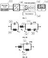
- a spectrometer 15 is required in order to measure an EIS spectrum on a generic PEFC system 13, comprising a stack of a fuel cell and other sub-systems and components (the so called Balance of Plant, BoP), connected to an electronic load 11 through a DC/DC converter 12, a spectrometer 15 is required.
- This spectrometer is able to measure the impedance Z of the whole system by measuring the current, drawn by the electronic load, and the voltage by means of four cables directly connected to the PEFC system 13 terminals.
- a controller unit 14 such as a Personal Computer (PC), controls the spectrometer 15 and displays the measured spectrum.
- PC Personal Computer
- Fig. 2A shows the ECM representing a generic PEFC system, each element being directly or indirectly related to a specific physical phenomenon characteristic of the PEFC.
- the left part of the ECM including the capacitor C dl 21 connected in parallel to the resistance R ct,a 22, represents the anode electrode behaviour.
- the resistance R ct,a 22 models the charge transfer resistance at the anode side
- the capacitor C dl 21 models the charge double layer phenomenon.
- the element R ⁇ 23 represents the resistance of the electrolyte.
- the resistance R ct,c 24 models the charge transfer resistance at cathode side.
- the element CPE 25 represents the Constant Phase Element (CPE), which models the charge double layer phenomenon in case of rough irregular surfaces (e.g. pores).
- the last element Zw 26 models the Warburg impedance, which is related to the diffusion processes at cathode side.
- the resistance R ct,c 24 is connected in series to the element Zw 26, thus forming a branch connected in parallel to the element CPE 25 and in series to the element R ⁇ 23, that in turn is connected in series to the parallel circuit including the capacitor C dl 21 and the resistance R ct,a 22.
- the aforementioned ECM is used to represent the impedance of a PEFC.
- the simple Randles ECM can be used.
- This circuit includes only the resistance R ⁇ 23 connected in series to the parallel circuit including the resistance R ct,c 24 and the element CPE 25, as shown in Fig. 2B .
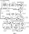
- Fig. 3 shows the flow chart of a preferred embodiment of the method for determining the state of an electrochemical device wherein the electrochemical device is a PEFC system.
- the method is executed automatically.
- the PEFC system operating conditions such as fuel cell (FC) temperature and drawn current
- FC fuel cell
- ⁇ 0 the ECM parameter models ⁇ 0
- Such parameter models ⁇ 0 are predetermined values related to (i.e. depending on) the operating conditions.
- These models are characterized by empirical expressions derived by experimental data (e.g. analytical functions of temperature and current).
- the parameter models can be represented by matrices with predetermined values.
- step 104 part of the parameters ⁇ 0 are exploited into the simple Randles ECM (i.e., the Randles ECM has the parameters ⁇ 0 ) to simulate the EIS spectrum Z s at the considered operating conditions.
- the first residual indicator I that indicates the difference between the two spectra Z' and Z s may be computed through a criterion different from the matrix 2-norm, such as the X-squared coefficient, still remaining within the scope of the invention.
- step 106 it is checked whether the first residual indicator I is greater than a first predetermined threshold ⁇ 1 . If the first residual indicator I is lower than or equal to the first predetermined threshold ⁇ 1 , the flow continues through the "NO" branch from step 106, whereby the method according to the invention recognises (step 107) that the PEFC system is running under normal conditions, i.e. it is in a normal operative state (namely, no malfunction is occurring), and the method ends (or return to step 101).
- step 106 if the first residual indicator I is greater than the first predetermined threshold ⁇ 1 , the flow continues through the "YES" branch from step 106, whereby the method according to the invention recognises that an unexpected event is occurring in the system and an identification procedure starts in step 108.
- This procedure is implemented by means of the ECM shown in Fig. 2A and it will be described in detail below.
- Such procedure is based on a Geometrical First Guess algorithm (GFG) for identification of a set of parameters ⁇ id ), related to the actual operative state, and of the spectrum Z id (corresponding to the ECM having parameters ⁇ id ).
- GFG Geometrical First Guess algorithm
- the second residual indicator I id ⁇ Z ′ ⁇ Z id ⁇ 2 ⁇ Z id ⁇ 2
- the second residual indicator I id may be computed through a criterion different from the matrix 2-norm, such as the X-squared coefficient, still remaining within the scope of the invention.
- step 110 it is checked whether the second residual indicator I id is greater than a second predetermined threshold ⁇ 2 . If the residual indicator I id computed through Eq.
- the vector residual indicator I ⁇ may be computed through a criterion different from the normalized difference, such as the mean square error (MSE), still remaining within the scope of the invention. If the residual indicator computed through Eq.
- step 110 the flow continues through the "YES" branch from step 110, whereby the method according to the invention recognises that the results might be affected by noise, and an alert is generated in step 111 before executing step 112 computing the vector residual indicator I ⁇ according to Eq. 3.
- the analysis of the computed vector residual indicator I ⁇ is performed defining a set of specific thresholds ⁇ 3 , each associated to a respective parameter and making a check in step 113: if all the residuals of the vector residual indicator I ⁇ lie within the respective defined threshold ranges (i.e. are lower than the respective threshold of the set ⁇ 3 ), the flow continues through the "NO" branch from step 113, wherein the method according to the invention recognises that the system is considered still near the normal operating condition. In such a case, the algorithm performed by the method according to the invention recognises that no fault is occurring in the system and one or more main losses are monitored in step 114. This step allows the method according to the invention to follow the system behaviour in terms of performance reduction.
- step 113 If at least one residual overcomes the respective threshold, the flow continues through the "YES" branch from step 113, whereby the method according to the invention recognises that an analytical symptom arises.
- This symptom consists in a binary number which represents the occurrence of a variable deviation from the normal conditions.
- FSM Fault to Symptoms Matrix
- a "1" one is present if a symptom is related to a specific fault, whereas a "0" (zero) if not.
- inventions may have the flow that continues through the "YES" branch from steps 106, 110 and 113 when the first residual indicator /, the second residual indicator I id and the residual vector I ⁇ , respectively, are not lower (instead of larger) than the first predetermined threshold ⁇ 1 , the second predetermined threshold ⁇ 2 and the set of specific thresholds ⁇ 3 (in other words, in these embodiments the equality between an indicator and the respective threshold causes the flow to follow the "YES" branch), still remaining within the scope of the invention.
- the identification procedure performed in step 108 allows the method according to the invention to achieve a reliable diagnosis of the system state.
- This procedure is based on a mathematical minimization algorithm which requires the definition of: i) the number of parameters to be identified (i.e. the ECM model components), and ii) the suitable starting values of these parameters.
- the GFG algorithm satisfies these two requirements.
- the GFG is capable to automatically detect the suitable ECM configuration and to select its proper starting parameters search space through a geometrical pre-analysis of the measured impedance spectrum Z' shape.
- Fig. 4 shows a flow chart of an automatic identification algorithm for the identification of the ECM parameter values implemented by the method according to the invention in step 108 of Fig. 3 .
- the first step 31 of this identification algorithm consists in acquiring the data measured by the EIS board (hence, it could also be coincident with step 103). Then, a data sampling is implemented on the frequencies in step 32.
- the sampling filters (i.e. deletes) the points with an imaginary part that is positive or close to zero (e.g. ⁇ 10 -3 ⁇ ), because these points can hinder reaching the convergence of the minimization procedure.
- the sampled data output are input to the GFG algorithm that starts in step 33, extrapolating the suitable ECM configuration and the parameter initial conditions.
- the GFG algorithm will be described later in detail with reference to the flow-chart depicted in Fig.6 associated to the ECM configurations sketched in Figs. 5A-5D .
- the sampled data and the detected suitable ECM configuration and parameters initial conditions outputs are input to a minimization algorithm (e.g. Complex Non-linear Least Square - CNLS - or another Non Linear Fitting algorithm) that is executed in step 34.
- the optimization algorithm, on which the minimization algorithm is based can be assumed for example being the Nelder-Mead algorithm (step 35).
- the goodness of fit is computed through a matrix 2-norm corresponding to the percent variation of the identified spectrum with respect to the measured one.
- step 37 it is checked whether the matrix 2-norm is less than a fixed reference value. If the matrix 2-norm is less than such fixed value, the flow continues through the "YES" branch from step 37, whereby the identification algorithm recognises that the fit quality is good, and the results are both input to step 109 of the algorithm shown in Fig. 3 (though this is not shown in Fig. 4 ) and saved in a file in the step 38 (shown in Fig. 4 ) before the procedure ends. If the matrix 2-norm exceeds or is equal to this fixed value level, the flow continues through the "NO" branch from step 37, and the starting parameters extrapolated by the GFG in step 33 are modified and the CNLS procedure starts again (step 34).
- the starting parameters modification is made randomly, although within a search space where the new parameter starting values keep the same order of magnitude of the old ones.
- Other embodiments of the present invention may use criterions for checking goodness of fit criterion different from the matrix 2-norm, such as the X-squared coefficient, as well as modifications of the starting values of the parameters different from the random modification, still remaining within the scope of the invention.
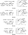
- Figs. 5A, 5B, 5C and 5D show all the possible ECM configurations, which are considered into the GFG algorithm modelling the PEFC behaviour.
- the complete ECM modelling a PEFC behaviour is shown in Fig. 5A .
- This ECM shows three time constants ⁇ associated to three arcs in the Nyquist plot of the related impedance spectrum. These arcs refers to the main phenomena occurring into the PEFC.
- the first arc on the left of the Nyquist plot refers to the charge transfer occurring at the anode side; the middle arc is related to the charge transfer at the cathode side; the last arc, on the right, corresponds to the diffusion.
- the PEFC cell physical phenomena might overlap and the number of the observable arcs of the related Nyquist plot of impedance spectrum reduces.
- the corresponding ECM is simplified: on the one hand, the Warburg element Zw can be neglected (as shown in Fig. 5B ) as the PEFC cell diffusion phenomenon is neglected; on the other hand, when the diffusion phenomenon must be taken into account rather than the anode side effects in PEFC cell, the corresponding ECM is reshaped as shown in Fig. 5C .
- These two last ECMs show both only two time constants ⁇ associated to two arcs in the related Nyquist plot of impedance.
- the last ECM shown in Fig 5D is the Randles ECM having only one time constant ⁇ associated to one arc in the related Nyquist plot of impedance, which corresponds to the charge transfer losses at cathode side. It is worth noting that when a change in the number of the arcs of the Nyquist plot occurs, its related Bode phase is also affected. For this reason, through the analysis of the first and the second derivatives of the Bode negative phase, it is possible to detect a change in the impedance shape.
- the GFG algorithm automatically choose among these ECMs just analysing specific features of the measured EIS spectrum of PEFC. If a physical phenomenon is negligible or absent, the GFG algorithm sets to zero the related parameters and the procedure removes them from the identification.
- the ECM configuration for the fit becomes one of those shown in Figs. 5A, 5B, 5C and 5D .
- a geometric analysis is performed to set the initial values of the parameters to be identified.
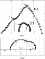
- step 201 the GFG algorithm starts: the GFG algorithm identifies the maximum value of the Bode plot negative phase (Point A in Fig. 7 ), which separates the high frequencies from the medium/low ones; then, polynomial regression curves are used to characterize the Bode plot at medium/low and high frequencies.
- Step 202 performs the evaluation of the derivatives of these polynomials with respect to the radial frequencies allowing the detection of the anodic and/or diffusion arcs.
- the number of arcs is set.
- the suitable ECM configuration is selected and the initial values of its parameters can be found through the parameters evaluation procedure (steps 203 through 209) described below also with reference to Fig. 8 .
- the first parameter set is the resistance R ⁇ , extrapolated as the intercept of the first arc with the real axis in the Nyquist plane in step 203 (see Fig. 8 , point 1 at the left side of the plot).
- the evaluation of the cathode charge transfer arc is performed analysing the information gathered in the Nyquist graph. Three points 1, 2 and 3 (shown in Fig.
- the Bode graph is selected according to the number of arcs present in the Bode graph. These points are chosen among those lying between the anodic charge transfer arc and the diffusion arc. If the anodic charge transfer arc is not present, the point with zero value imaginary part and real part equal to R ⁇ is chosen as the first point 1, corresponding to the first point of the cathode charge transfer arc. If the charge transfer anodic arc is present, the first point 1 is chosen among the sampled data as the last one belonging to the aforementioned anodic charge transfer arc. The information about how many sampled measured points belong to each arc is obtained in step 202 through the Bode plot considering the inflection points.
- the second point 2 is chosen as the second interception of the sampled measured spectrum Z' with the real axis. Differently, if the diffusion arc is present, the second point 2 is chosen in the range of point B (shown in Fig. 7 ), e.g. three or four points before (as shown in Fig. 8 ). The third point 3 is chosen as the mean point among the first and the second point 1 and 2 respectively. A circumference is then achieved by interpolation of the aforementioned points and taking into account also the sampled measured ones laying among these points, so as to avoid any abnormal deviation of the measurements.
- the coordinates of its centre 5 and of its first and second intercepts 6, 4, respectively, with the real axis are computed. If the anodic arc is not present the first intercept 6 corresponds to the first point 1 as shown in Fig. 8 .
- Step 205 in Fig. 6 considers the presence of the anodic charge transfer arc. If the anodic charge transfer arc is present, the flow continues through the branch "Yes" from step 205, and the anode parameters are computed in block 206.
- the anodic charge transfer resistance R ct,a is computed as the difference between the first intercept 6 of the semi-circle and the value obtained for R ⁇ .
- the cathode charge transfer resistance R ct,c is obtained as the difference between the second intercept 4 and the first intercept 6. These points have only real part (i.e. imaginary part equal to zero).
- the last element to be computed is the Warburg element Zw. This element is related to the diffusion phenomenon, and it is introduced in the ECM only if the diffusion arc is present, whereby the flow continues through the branch "Yes" from step 208 and the diffusion parameters are computed in block 209.
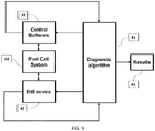
- Fig. 9 a schematic block diagram of a configuration of the method 41 for determining the state of an electrochemical device according to the invention wherein the electrochemical device is a generic fuel cell system 44 and an EIS measurement device 42 according to a preferred embodiment is given.
- the method 41 communicates with the EIS device 42 and the system control software 43 to send and receive information (e.g. operating conditions such as FC temperature and drawn currents ,measured EIS spectra, FC state evaluation).
- the EIS board 42 and the system control software 43 measures the data on the system 44.
- the EIS board 42 sends a feedback to the method 41 to allow the evaluation of the system state, and the information can be exploited by the system control software 43 to avoid dangerous operations; also, the results 45 obtained by the method 41 may be transmitted or displayed to an operator.
- Fig. 9 may be also construed as showing a schematic block diagram of a configuration including the preferred embodiment of an apparatus including processing means (e.g. a personal computer) executing the method for determining the state of an electrochemical device according to the invention, wherein block 41 represents such apparatus, provided with a display (or communication unit) 45, that communicates with an interface 43 of the system controlling the fuel cell system 44 and with the EIS device 42.
- block 41 represents such apparatus, provided with a display (or communication unit) 45, that communicates with an interface 43 of the system controlling the fuel cell system 44 and with the EIS device 42.
- other embodiments of the apparatus according to the invention may be incorporated into the system controlling the fuel cell system 44, whereby the apparatus executes both the system control software and the method for monitoring and diagnosis of an electrochemical device according to the invention.
Landscapes
- Chemical & Material Sciences (AREA)
- Chemical Kinetics & Catalysis (AREA)
- Electrochemistry (AREA)
- Physics & Mathematics (AREA)
- General Physics & Mathematics (AREA)
- Engineering & Computer Science (AREA)
- Manufacturing & Machinery (AREA)
- General Chemical & Material Sciences (AREA)
- Life Sciences & Earth Sciences (AREA)
- Sustainable Development (AREA)
- Sustainable Energy (AREA)
- Spectroscopy & Molecular Physics (AREA)
- Biochemistry (AREA)
- General Health & Medical Sciences (AREA)
- Immunology (AREA)
- Pathology (AREA)
- Analytical Chemistry (AREA)
- Health & Medical Sciences (AREA)
- Fuel Cell (AREA)
Claims (11)
- Verfahren zur Bestimmung des Zustands einer elektrochemischen Vorrichtung auf der Grundlage einer automatischen
elektrochemische Impedanzidentifizierung, wobei das Verfahren die folgenden Schritte umfasst:A. Messung (101) der Betriebsbedingungen des elektrochemischen Geräts und Sammlung von Informationen;B. Bestimmung (102) der Parameter ßo, eines Randles-Ersatzschaltbildes (ECM) auf der Grundlage der gemessenen Betriebsbedingungen;C. Messung (103) des Impedanzspektrums Z'der elektrochemischen Vorrichtung mit einem Gerät für elektrochemische Impedanzspektroskopie (EIS);D. Simulieren (104) eines EIS-Spektrums Zs der Randles-ECM mit den ermittelten Parametern ßo;E. Berechnung (105) eines ersten Restindikators I, der eine Differenz zwischen dem gemessenen Impedanzspektrum Z' und dem simulierten EIS-Spektrum Zs der Randles-ECM angibt;F. Prüfung (106), ob der erste Restvektor I größer als ein erster vorbestimmter Schwellenwert ε1 ist;G. wenn der Restindikator I niedriger als der erste vorbestimmte Schwellenwert ε1 ist, erkennen, dass sich die elektrochemische Vorrichtung in einem normalen Betriebszustand befindet, und die Ausführung des Verfahrens beenden;H. wenn der Restindikator I größer als der erste vorbestimmte Schwellenwert ε1 ist, Starten (108) eines automatischen Identifizierungsverfahrens zum Identifizieren eines Satzes von Parametern βid , die mit dem tatsächlichen Betriebszustand der elektrochemischen Vorrichtung und einem Spektrum Zid , das einem ECM mit Parametern β id entspricht, wobei das automatische Identifizierungsverfahren auf einem Geometrical First Guess (GFG)-Algorithmus basiert, der einen mathematischen Minimierungsalgorithmus durchführt, der eine Anzahl von zu identifizierenden Parametern definiert, wodurch die ECM-Komponenten identifiziert werden, und Startwerte dieser zu identifizierenden Parameter, wobei der GFG automatisch ein ECM erkennt und den Startparameter-Suchraum durch eine geometrische Voranalyse der Form des gemessenen Impedanzspektrums Z' auswählt;I. Berechnung (109) eines zweiten Restindikators Iid , der eine Differenz zwischen dem gemessenen Impedanzspektrum Z' und dem Spektrum Zid anzeigt, das der ECM mit den Parametern βid entspricht;J. Prüfung (110), ob der zweite Restindikator größer als ein zweiter vorbestimmter Schwellenwert ε2 ist;K. wenn der Restindikator I größer als der zweite vorbestimmte Schwellenwer ε2 ist, erkennen, dass die Ausführung des Verfahrens durch Rauschen beeinträchtigt sein könnte, und erzeugen einer Warnmeldung (111);L. Berechnung (112) eines Vektor-Residualindikators Iβ , der einen Satz von Residuen enthält, die eine Differenz zwischen den identifizierten Parametern βid und den ermittelten Parametern β0 anzeigen;M. Prüfung (113), ob der Vektor-Restindikator Iβ größer ist als eine Reihe spezifischer Schwellenwerte ε3 , die jeweils einem bestimmten Parameter zugeordnet sind;N. wenn alle Residuen des Vektor-Residuen-Indikators Iβ niedriger sind als die jeweiligen Schwellenwerte des Satzes ε3 , Erkennen (114), dass die elektrochemische Vorrichtung sich in der Nähe eines normalen Betriebszustands befindet, wodurch erkannt wird, dass kein Fehler in der elektrochemischen Vorrichtung auftritt, und Beenden der Ausführung des Verfahrens;O. wenn mindestens einer der Residuen des Vektor-Restindikators Iβ größer als der jeweilige Schwellenwert des Satzes ε3 ist, Abgleichen (115) von Symptomen, die variable Abweichungen von den normalen Bedingungen darstellen, mit den gesammelten Informationen in einer Fehler-Symptom-Matrix (FSM); undP. Ableitung (116) des Betriebszustands der elektrochemischen Vorrichtung auf der Grundlage des FSM, wobei mindestens ein bestimmter Fehler in der elektrochemischen Vorrichtung isoliert wird. - Verfahren nach Anspruch 1, wobei Schritt H eine automatische Identifizierung (108) startet Das Verfahren zur Identifizierung eines Satzes von Parametern βid , die sich auf den tatsächlichen Betriebszustand der elektrochemischen Vorrichtung beziehen, und eines Spektrums Zid , das einer ECM mit Parametern β id entspricht, umfassend die folgenden Teilschritte:H.1 Abtastung (32) der in Schritt C gemessenen Daten, wobei die Punkte mit Imaginärteil gefiltert werden die positiv oder nahe Null sind, werden gefiltert,H.2 Eingabe (33) der gefilterten Abtastdaten in den Geometrical First Guess (GFG)-Algorithmus,H.3 Eingabe (34) der gefilterten Abtastdaten, der identifizierten ECM-Komponenten und der identifizierten Ausgangswerte der zu identifizierenden Parameter in einen auf einem Optimierungsalgorithmus (35) basierenden Minimierungsalgorithmus,H.4 Berechnung (36) der Anpassungsgüte des der ECM mit den Parametern βid entsprechenden Spektrums Zid an das gemessene Impedanzspektrum Z',H.5 Prüfung (37), ob die Anpassungsgüte in Bezug auf einen festen Referenzwert ausreichend ist,H.6 wenn die Anpassungsgüte ausreichend ist, wird mit Schritt I fortgefahren,H.7 wenn die Anpassungsgüte nicht ausreicht, Änderung der Ausgangswerte der zu ermittelnden Parameter und Rückkehr zu Teilschritt H.3.
- Verfahren nach Anspruch 2, wobei in Unterschritt H.3 der Minimierungsalgorithmus ein nichtlinearer Anpassungsalgorithmus, optional ein komplexer nichtlinearer Least Square (CNLS), und/oder der Optimierungsalgorithmus ein Nelder-Mead-Algorithmus ist.
- Verfahren nach Anspruch 2 oder 3, wobei in Unterschritt H.4 die Anpassungsgüte durch eine Größe berechnet wird, die aus der Gruppe ausgewählt wird, die eine Matrix-2-Norm, die der prozentualen Abweichung des Spektrums Zid in Bezug auf das gemessene Impedanzspektrum Z' entspricht, und einen X-Quadrat-Koeffizienten umfasst, wobei in Unterschritt H.5 diese Größe mit dem festen Referenzwert verglichen wird.
- Verfahren nach einem der Ansprüche 2 bis 4, wobei in Schritt H.6 die ECM mit den Parametern βid und gegebenenfalls das entsprechende Spektrum Zid in einer Datei gespeichert (38) werden.
- Verfahren nach einem der Ansprüche 2 bis 5, wobei im Teilschritt H.7 die Startwerte der zu identifizierenden Parameter innerhalb des Suchraumes zufällig so verändert werden, dass die neuen Parameter-Startwerte die gleiche Größenordnung wie die alten Parameter-Startwerte behalten.
- Verfahren nach einem der Ansprüche 2 bis 6, wobei der GFG-Algorithmus in Schritt H die folgenden Teilschritte umfasst:H.8 Identifizierung (201) eines Maximalwerts der negativen Phase in einem Bode-Diagramm des gemessenen Impedanzspektrums Z', der die hohen Frequenzen von den mittleren/niedrigen Frequenzen trennt, und Charakterisierung des Bode-Diagramms durch Verwendung polynomialer Regressionskurven,H.9 Auswerten (202) der Ableitungen der polynomialen Regressionskurven in Bezug auf die radialen Frequenzen, wodurch die anodischen und/oder Diffusionsbögen des Bode-Plots erfasst werden, so dass alle Wendepunkte identifiziert werden und somit die Anzahl der Bögen festgelegt wird,H.10 Einstellung (203) eines Widerstandes RΩ , der als Schnittpunkt eines ersten Linksbogens des gemessenen Impedanzspektrums Z' mit der reellen Achse in der Nyquist-Ebene extrapoliert wird,H.11 Auswerten (204) eines Kathoden-Ladungstransferbogens durch Auswählen von drei Punkten unter denen, die zwischen dem anodischen Ladungstransferbogen und dem Diffusionsbogen des Bode-Diagramms liegen, entsprechend einer Anzahl von Bögen, die in dem Bode-Diagramm vorhanden sind, wobei:- wenn der anodische Ladungsübertragungsbogen nicht vorhanden ist, wird ein Punkt mit einem Imaginärteil von Null und einem Realteil gleich R Ω als erster Punkt gewählt, der dem ersten Punkt des kathodischen Ladungsübertragungsbogens entspricht,- wenn der anodische Ladungstransferbogen vorhanden ist, wird der erste Punkt unter den gefilterten Abtastdaten als der letzte Punkt ausgewählt, der zum anodischen Ladungstransferbogen gehört, wobei die Information, wie viele abgetastete Messpunkte zu jedem Bogen gehören, in Teilschritt H.9 durch den Bode-Plot unter Berücksichtigung der Wendepunkte gewonnen wird,- wenn der Diffusionsbogen nicht vorhanden ist, wird der zweite Punkt als zweiter Schnittpunkt des gemessenen Impedanzspektrums Z' mit der realen Achse gewählt,- wenn der Diffusionsbogen vorhanden ist, wird der zweite Punkt im Bereich eines Wendepunktes gewählt, optional drei oder vier Punkte vor dem Wendepunkt,- der dritte Punkt wird als Mittelwert zwischen dem ersten und dem zweiten Punkt gewählt,- ein Umfang durch Interpolation der drei Punkte erhalten wird und die Koordinaten seines Mittelpunkts und seines ersten und zweiten Schnittpunkts mit der realen Achse berechnet werden, wobei, wenn der anodische Bogen nicht vorhanden ist, der erste Schnittpunkt dem ersten Punkt entspricht,H.12 wenn der anodische Ladungsübertragungsbogen vorhanden ist, Berechnen (206) von Anodenparametern, so dass ein anodischer Ladungsübertragungswiderstand Rct, a als Differenz zwischen dem ersten Schnittpunkt des genannten Umfangs und dem für den Widerstand RΩ erhaltenen Wert berechnet wird, und ein Kondensator Cdl wie folgt berechnet wird:
 H.13 Berechnung (207) von Kathodenparametern, so dass ein Kathoden-Ladungsübergangswiderstand Rct,c als Differenz zwischen dem zweiten Schnittpunkt und dem ersten Schnittpunkt erhalten wird, und ein Element CPE (25), das ein Konstantphasenelement darstellt, wird durch die Berücksichtigung eines äquivalenten Kondensators wie folgt charakterisiert:


 H.14 wenn der Diffusionsbogen vorhanden ist, Berechnung eines Warburg-Elements Zw in Abhängigkeit von den Parametern Rd und τd wie folgt:

 H.15 Ausgabe an β = [ RΩ , Rct,a, Cdl, Rct,c, Q, φ, Rd, τd ] Teilschritt H.3, optional Speichern des Vektors β in einer Datei.
 - Verfahren nach einem der vorhergehenden Ansprüche, wobei der erste Restvektor / in Schritt E durch eine 2-Norm-Matrix des gemessenen Impedanzspektrums Z' und des EIS-Spektrums Zs des Randles-Ersatzschaltungsmodells (ECM) mit den bestimmten Parametern wie β0 folgt berechnet wird:


- Verfahren nach einem der vorhergehenden Ansprüche, wobei der Vektor-Restindikator Iβ in Schritt L als normalisierte Differenz zwischen dem identifizierten Parameter βid und den ermittelten Parametern wie β0 folgt berechnet wird:

- Verfahren nach einem der vorhergehenden Ansprüche, wobei die elektrochemische Vorrichtung ein Polymerelektrolyt-Brennstoffzellensystem (PEFC) umfasst.
- Vorrichtung zur Bestimmung des Zustands einer elektrochemischen Vorrichtung, die eine elektrochemische Impedanzspektroskopie (EIS)-Vorrichtung und Verarbeitungsmittel umfasst, die so konfiguriert sind, dass sie das Verfahren zur Bestimmung des Zustands einer elektrochemischen Vorrichtung nach einem der Ansprüche 1 bis 10 ausführen.
Applications Claiming Priority (2)
| Application Number | Priority Date | Filing Date | Title |
|---|---|---|---|
| ITRM20140641 | 2014-11-04 | ||
| PCT/IB2015/058258 WO2016071801A1 (en) | 2014-11-04 | 2015-10-27 | Method and apparatus for monitoring and diagnosing electrochemical devices based on automatic electrochemical impedance identification |
Publications (2)
| Publication Number | Publication Date |
|---|---|
| EP3215832A1 EP3215832A1 (de) | 2017-09-13 |
| EP3215832B1 true EP3215832B1 (de) | 2022-05-04 |
Family
ID=52273394
Family Applications (1)
| Application Number | Title | Priority Date | Filing Date |
|---|---|---|---|
| EP15805259.7A Active EP3215832B1 (de) | 2014-11-04 | 2015-10-27 | Verfahren und vorrichtung zur überwachung und diagnose elektrochemischer geräte basierend auf einer automatischen erkennung der elektrochemischen impedanz |
Country Status (2)
| Country | Link |
|---|---|
| EP (1) | EP3215832B1 (de) |
| WO (1) | WO2016071801A1 (de) |
Families Citing this family (8)
| Publication number | Priority date | Publication date | Assignee | Title |
|---|---|---|---|---|
| JP7070044B2 (ja) * | 2018-04-26 | 2022-05-18 | トヨタ自動車株式会社 | 電池情報処理システム、電池モジュールの満充電容量算出方法、電池モジュールの内部抵抗算出方法、および、組電池の製造方法 |
| WO2020022124A1 (ja) * | 2018-07-23 | 2020-01-30 | 国立研究開発法人物質・材料研究機構 | インピーダンススペクトルデータを用いた解析処理方法、インピーダンススペクトルデータ解析処理システム、および、インピーダンススペクトル解析処理プログラム |
| FR3088440B1 (fr) | 2018-11-14 | 2020-10-30 | Commissariat Energie Atomique | Procede de diagnostic d'une pile a combustible |
| AT522011A3 (de) * | 2018-12-20 | 2021-03-15 | Avl List Gmbh | Betriebsvorrichtung, Brennstoffzellensystem, Kraftfahrzeug und Verfahren zum Betreiben eines Brennstoffzellensystems |
| EP3812779B1 (de) * | 2019-10-23 | 2022-09-28 | Novum engineerING GmbH | Analyse elektrischer impedanzmessungen einer elektrochemischen batterie |
| WO2022177764A1 (en) * | 2021-02-17 | 2022-08-25 | Analog Devices, Inc. | Eis monitoring systems for electrolyzers |
| CN114664392B (zh) * | 2022-05-26 | 2022-09-09 | 季华实验室 | 电化学参数预测方法、装置、电子设备及可读存储介质 |
| WO2023229879A1 (en) * | 2022-05-27 | 2023-11-30 | Cummins Inc. | Control systems and methods for monitoring electrolyzer cell stack conditions and extending operational life |
Family Cites Families (7)
| Publication number | Priority date | Publication date | Assignee | Title |
|---|---|---|---|---|
| WO1998040951A1 (en) | 1997-03-12 | 1998-09-17 | Us Nanocorp. | Method for determining state-of-health using an intelligent system |
| US20030184307A1 (en) * | 2002-02-19 | 2003-10-02 | Kozlowski James D. | Model-based predictive diagnostic tool for primary and secondary batteries |
| CN1930718A (zh) | 2004-03-12 | 2007-03-14 | 松下电器产业株式会社 | 燃料电池系统的故障诊断方法和采用该方法的故障诊断装置及燃料电池系统 |
| US20050287402A1 (en) | 2004-06-23 | 2005-12-29 | Maly Douglas K | AC impedance monitoring of fuel cell stack |
| JP4821962B2 (ja) | 2005-06-30 | 2011-11-24 | トヨタ自動車株式会社 | 燃料電池システム |
| JP2008010367A (ja) | 2006-06-30 | 2008-01-17 | Toyota Motor Corp | 燃料電池診断装置および診断方法 |
| KR20100121354A (ko) | 2009-05-08 | 2010-11-17 | 삼성전자주식회사 | 연료 전지의 열화를 진단하는 방법 및 장치 |
-
2015
- 2015-10-27 WO PCT/IB2015/058258 patent/WO2016071801A1/en active Application Filing
- 2015-10-27 EP EP15805259.7A patent/EP3215832B1/de active Active
Also Published As
| Publication number | Publication date |
|---|---|
| WO2016071801A1 (en) | 2016-05-12 |
| EP3215832A1 (de) | 2017-09-13 |
Similar Documents
| Publication | Publication Date | Title |
|---|---|---|
| EP3215832B1 (de) | Verfahren und vorrichtung zur überwachung und diagnose elektrochemischer geräte basierend auf einer automatischen erkennung der elektrochemischen impedanz | |
| Kang et al. | Online multi-fault detection and diagnosis for battery packs in electric vehicles | |
| Wu et al. | A new fault diagnosis and prognosis technology for high-power lithium-ion battery | |
| US11327118B2 (en) | Battery capacity estimation method and battery capacity estimation device | |
| Schmid et al. | Early detection of internal short circuits in series-connected battery packs based on nonlinear process monitoring | |
| CN108957349A (zh) | 一种锂离子电池故障检测方法和系统 | |
| US20220146589A1 (en) | Method and device for predicting state of health and remaining lifetime for used electric vehicle batteries | |
| Zhang et al. | Phm‐oriented degradation indicators for batteries and fuel cells | |
| CN113561853B (zh) | 燃料电池系统在线故障诊断方法及装置 | |
| CN116053531A (zh) | 一种燃料电池堆健康状态的评估系统及方法 | |
| CN110927609B (zh) | 梯次利用电池储能系统的衰退评估方法及装置 | |
| CN108693478A (zh) | 一种锂离子动力电池的漏液检测方法 | |
| CN115248382A (zh) | 一种质子交换膜燃料电池控制方法 | |
| US20180267111A1 (en) | Method for monitoring a battery | |
| JP2023543747A (ja) | 電池診断装置および方法 | |
| JP2010044000A (ja) | 電池のインピーダンス特性評価方法、インピーダンス特性評価装置、制御方法および制御装置 | |
| Buonocunto et al. | A Kalman filter based approach to PEM fuel cell fault detection | |
| KR101511866B1 (ko) | 연료전지 스택의 고장 진단 방법 및 이를 실행하는 장치 | |
| Wu et al. | Control‐oriented fault detection of solid oxide fuel cell system unknown input on fuel supply | |
| CN109888338B (zh) | 基于统计的sofc供气故障检测方法及设备 | |
| CN112162164A (zh) | 一种基于神经网络的电缆寿命预测系统 | |
| Wu et al. | Research on short-circuit fault-diagnosis strategy of lithium-ion battery in an energy-storage system based on voltage cosine similarity | |
| KR101607759B1 (ko) | 연료전지 스택의 상태 진단 장치 및 그 방법 | |
| Xu et al. | An Adaptive Neural Observer for Short Circuit Fault Estimation of Lithium-ion Batteries in Electric Vehicles | |
| CN112039074B (zh) | 一种在线安全稳定紧急控制策略方式字生成方法 |
Legal Events
| Date | Code | Title | Description |
|---|---|---|---|
| STAA | Information on the status of an ep patent application or granted ep patent |
Free format text: STATUS: THE INTERNATIONAL PUBLICATION HAS BEEN MADE |
|
| PUAI | Public reference made under article 153(3) epc to a published international application that has entered the european phase |
Free format text: ORIGINAL CODE: 0009012 |
|
| STAA | Information on the status of an ep patent application or granted ep patent |
Free format text: STATUS: REQUEST FOR EXAMINATION WAS MADE |
|
| 17P | Request for examination filed |
Effective date: 20170508 |
|
| AK | Designated contracting states |
Kind code of ref document: A1 Designated state(s): AL AT BE BG CH CY CZ DE DK EE ES FI FR GB GR HR HU IE IS IT LI LT LU LV MC MK MT NL NO PL PT RO RS SE SI SK SM TR |
|
| AX | Request for extension of the european patent |
Extension state: BA ME |
|
| DAV | Request for validation of the european patent (deleted) | ||
| DAX | Request for extension of the european patent (deleted) | ||
| STAA | Information on the status of an ep patent application or granted ep patent |
Free format text: STATUS: EXAMINATION IS IN PROGRESS |
|
| 17Q | First examination report despatched |
Effective date: 20190710 |
|
| STAA | Information on the status of an ep patent application or granted ep patent |
Free format text: STATUS: EXAMINATION IS IN PROGRESS |
|
| GRAP | Despatch of communication of intention to grant a patent |
Free format text: ORIGINAL CODE: EPIDOSNIGR1 |
|
| STAA | Information on the status of an ep patent application or granted ep patent |
Free format text: STATUS: GRANT OF PATENT IS INTENDED |
|
| INTG | Intention to grant announced |
Effective date: 20211129 |
|
| GRAS | Grant fee paid |
Free format text: ORIGINAL CODE: EPIDOSNIGR3 |
|
| GRAA | (expected) grant |
Free format text: ORIGINAL CODE: 0009210 |
|
| STAA | Information on the status of an ep patent application or granted ep patent |
Free format text: STATUS: THE PATENT HAS BEEN GRANTED |
|
| AK | Designated contracting states |
Kind code of ref document: B1 Designated state(s): AL AT BE BG CH CY CZ DE DK EE ES FI FR GB GR HR HU IE IS IT LI LT LU LV MC MK MT NL NO PL PT RO RS SE SI SK SM TR |
|
| REG | Reference to a national code |
Ref country code: GB Ref legal event code: FG4D |
|
| REG | Reference to a national code |
Ref country code: CH Ref legal event code: EP |
|
| REG | Reference to a national code |
Ref country code: AT Ref legal event code: REF Ref document number: 1489564 Country of ref document: AT Kind code of ref document: T Effective date: 20220515 |
|
| REG | Reference to a national code |
Ref country code: DE Ref legal event code: R096 Ref document number: 602015078740 Country of ref document: DE |
|
| REG | Reference to a national code |
Ref country code: IE Ref legal event code: FG4D |
|
| REG | Reference to a national code |
Ref country code: LT Ref legal event code: MG9D |
|
| REG | Reference to a national code |
Ref country code: NL Ref legal event code: MP Effective date: 20220504 |
|
| REG | Reference to a national code |
Ref country code: AT Ref legal event code: MK05 Ref document number: 1489564 Country of ref document: AT Kind code of ref document: T Effective date: 20220504 |
|
| PG25 | Lapsed in a contracting state [announced via postgrant information from national office to epo] |
Ref country code: SE Free format text: LAPSE BECAUSE OF FAILURE TO SUBMIT A TRANSLATION OF THE DESCRIPTION OR TO PAY THE FEE WITHIN THE PRESCRIBED TIME-LIMIT Effective date: 20220504 Ref country code: PT Free format text: LAPSE BECAUSE OF FAILURE TO SUBMIT A TRANSLATION OF THE DESCRIPTION OR TO PAY THE FEE WITHIN THE PRESCRIBED TIME-LIMIT Effective date: 20220905 Ref country code: NO Free format text: LAPSE BECAUSE OF FAILURE TO SUBMIT A TRANSLATION OF THE DESCRIPTION OR TO PAY THE FEE WITHIN THE PRESCRIBED TIME-LIMIT Effective date: 20220804 Ref country code: NL Free format text: LAPSE BECAUSE OF FAILURE TO SUBMIT A TRANSLATION OF THE DESCRIPTION OR TO PAY THE FEE WITHIN THE PRESCRIBED TIME-LIMIT Effective date: 20220504 Ref country code: LT Free format text: LAPSE BECAUSE OF FAILURE TO SUBMIT A TRANSLATION OF THE DESCRIPTION OR TO PAY THE FEE WITHIN THE PRESCRIBED TIME-LIMIT Effective date: 20220504 Ref country code: HR Free format text: LAPSE BECAUSE OF FAILURE TO SUBMIT A TRANSLATION OF THE DESCRIPTION OR TO PAY THE FEE WITHIN THE PRESCRIBED TIME-LIMIT Effective date: 20220504 Ref country code: GR Free format text: LAPSE BECAUSE OF FAILURE TO SUBMIT A TRANSLATION OF THE DESCRIPTION OR TO PAY THE FEE WITHIN THE PRESCRIBED TIME-LIMIT Effective date: 20220805 Ref country code: FI Free format text: LAPSE BECAUSE OF FAILURE TO SUBMIT A TRANSLATION OF THE DESCRIPTION OR TO PAY THE FEE WITHIN THE PRESCRIBED TIME-LIMIT Effective date: 20220504 Ref country code: ES Free format text: LAPSE BECAUSE OF FAILURE TO SUBMIT A TRANSLATION OF THE DESCRIPTION OR TO PAY THE FEE WITHIN THE PRESCRIBED TIME-LIMIT Effective date: 20220504 Ref country code: BG Free format text: LAPSE BECAUSE OF FAILURE TO SUBMIT A TRANSLATION OF THE DESCRIPTION OR TO PAY THE FEE WITHIN THE PRESCRIBED TIME-LIMIT Effective date: 20220804 Ref country code: AT Free format text: LAPSE BECAUSE OF FAILURE TO SUBMIT A TRANSLATION OF THE DESCRIPTION OR TO PAY THE FEE WITHIN THE PRESCRIBED TIME-LIMIT Effective date: 20220504 |
|
| PG25 | Lapsed in a contracting state [announced via postgrant information from national office to epo] |
Ref country code: RS Free format text: LAPSE BECAUSE OF FAILURE TO SUBMIT A TRANSLATION OF THE DESCRIPTION OR TO PAY THE FEE WITHIN THE PRESCRIBED TIME-LIMIT Effective date: 20220504 Ref country code: PL Free format text: LAPSE BECAUSE OF FAILURE TO SUBMIT A TRANSLATION OF THE DESCRIPTION OR TO PAY THE FEE WITHIN THE PRESCRIBED TIME-LIMIT Effective date: 20220504 Ref country code: LV Free format text: LAPSE BECAUSE OF FAILURE TO SUBMIT A TRANSLATION OF THE DESCRIPTION OR TO PAY THE FEE WITHIN THE PRESCRIBED TIME-LIMIT Effective date: 20220504 Ref country code: IS Free format text: LAPSE BECAUSE OF FAILURE TO SUBMIT A TRANSLATION OF THE DESCRIPTION OR TO PAY THE FEE WITHIN THE PRESCRIBED TIME-LIMIT Effective date: 20220904 |
|
| PG25 | Lapsed in a contracting state [announced via postgrant information from national office to epo] |
Ref country code: SM Free format text: LAPSE BECAUSE OF FAILURE TO SUBMIT A TRANSLATION OF THE DESCRIPTION OR TO PAY THE FEE WITHIN THE PRESCRIBED TIME-LIMIT Effective date: 20220504 Ref country code: SK Free format text: LAPSE BECAUSE OF FAILURE TO SUBMIT A TRANSLATION OF THE DESCRIPTION OR TO PAY THE FEE WITHIN THE PRESCRIBED TIME-LIMIT Effective date: 20220504 Ref country code: RO Free format text: LAPSE BECAUSE OF FAILURE TO SUBMIT A TRANSLATION OF THE DESCRIPTION OR TO PAY THE FEE WITHIN THE PRESCRIBED TIME-LIMIT Effective date: 20220504 Ref country code: EE Free format text: LAPSE BECAUSE OF FAILURE TO SUBMIT A TRANSLATION OF THE DESCRIPTION OR TO PAY THE FEE WITHIN THE PRESCRIBED TIME-LIMIT Effective date: 20220504 Ref country code: DK Free format text: LAPSE BECAUSE OF FAILURE TO SUBMIT A TRANSLATION OF THE DESCRIPTION OR TO PAY THE FEE WITHIN THE PRESCRIBED TIME-LIMIT Effective date: 20220504 Ref country code: CZ Free format text: LAPSE BECAUSE OF FAILURE TO SUBMIT A TRANSLATION OF THE DESCRIPTION OR TO PAY THE FEE WITHIN THE PRESCRIBED TIME-LIMIT Effective date: 20220504 |
|
| REG | Reference to a national code |
Ref country code: DE Ref legal event code: R097 Ref document number: 602015078740 Country of ref document: DE |
|
| PLBE | No opposition filed within time limit |
Free format text: ORIGINAL CODE: 0009261 |
|
| STAA | Information on the status of an ep patent application or granted ep patent |
Free format text: STATUS: NO OPPOSITION FILED WITHIN TIME LIMIT |
|
| PG25 | Lapsed in a contracting state [announced via postgrant information from national office to epo] |
Ref country code: AL Free format text: LAPSE BECAUSE OF FAILURE TO SUBMIT A TRANSLATION OF THE DESCRIPTION OR TO PAY THE FEE WITHIN THE PRESCRIBED TIME-LIMIT Effective date: 20220504 |
|
| 26N | No opposition filed |
Effective date: 20230207 |
|
| PG25 | Lapsed in a contracting state [announced via postgrant information from national office to epo] |
Ref country code: SI Free format text: LAPSE BECAUSE OF FAILURE TO SUBMIT A TRANSLATION OF THE DESCRIPTION OR TO PAY THE FEE WITHIN THE PRESCRIBED TIME-LIMIT Effective date: 20220504 |
|
| PG25 | Lapsed in a contracting state [announced via postgrant information from national office to epo] |
Ref country code: LU Free format text: LAPSE BECAUSE OF NON-PAYMENT OF DUE FEES Effective date: 20221027 |
|
| PGFP | Annual fee paid to national office [announced via postgrant information from national office to epo] |
Ref country code: GB Payment date: 20231018 Year of fee payment: 9 |
|
| PGFP | Annual fee paid to national office [announced via postgrant information from national office to epo] |
Ref country code: MC Payment date: 20231017 Year of fee payment: 9 |
|
| PGFP | Annual fee paid to national office [announced via postgrant information from national office to epo] |
Ref country code: IT Payment date: 20231017 Year of fee payment: 9 Ref country code: IE Payment date: 20231030 Year of fee payment: 9 Ref country code: FR Payment date: 20231018 Year of fee payment: 9 Ref country code: DE Payment date: 20231016 Year of fee payment: 9 Ref country code: CH Payment date: 20231102 Year of fee payment: 9 |
|
| PGFP | Annual fee paid to national office [announced via postgrant information from national office to epo] |
Ref country code: BE Payment date: 20231023 Year of fee payment: 9 |
|
| PG25 | Lapsed in a contracting state [announced via postgrant information from national office to epo] |
Ref country code: HU Free format text: LAPSE BECAUSE OF FAILURE TO SUBMIT A TRANSLATION OF THE DESCRIPTION OR TO PAY THE FEE WITHIN THE PRESCRIBED TIME-LIMIT; INVALID AB INITIO Effective date: 20151027 |
|
| PG25 | Lapsed in a contracting state [announced via postgrant information from national office to epo] |
Ref country code: CY Free format text: LAPSE BECAUSE OF FAILURE TO SUBMIT A TRANSLATION OF THE DESCRIPTION OR TO PAY THE FEE WITHIN THE PRESCRIBED TIME-LIMIT Effective date: 20220504 |