EP3215424B1 - Device for the filling and/or closing of containers having a drive shaft decontamination box. - Google Patents
Device for the filling and/or closing of containers having a drive shaft decontamination box. Download PDFInfo
- Publication number
- EP3215424B1 EP3215424B1 EP15820318.2A EP15820318A EP3215424B1 EP 3215424 B1 EP3215424 B1 EP 3215424B1 EP 15820318 A EP15820318 A EP 15820318A EP 3215424 B1 EP3215424 B1 EP 3215424B1
- Authority
- EP
- European Patent Office
- Prior art keywords
- sterilization
- suction chamber
- chamber
- media
- pressure
- Prior art date
- Legal status (The legal status is an assumption and is not a legal conclusion. Google has not performed a legal analysis and makes no representation as to the accuracy of the status listed.)
- Active
Links
Images


Classifications
-
- B—PERFORMING OPERATIONS; TRANSPORTING
- B65—CONVEYING; PACKING; STORING; HANDLING THIN OR FILAMENTARY MATERIAL
- B65B—MACHINES, APPARATUS OR DEVICES FOR, OR METHODS OF, PACKAGING ARTICLES OR MATERIALS; UNPACKING
- B65B55/00—Preserving, protecting or purifying packages or package contents in association with packaging
- B65B55/02—Sterilising, e.g. of complete packages
- B65B55/025—Packaging in aseptic tunnels
-
- B—PERFORMING OPERATIONS; TRANSPORTING
- B65—CONVEYING; PACKING; STORING; HANDLING THIN OR FILAMENTARY MATERIAL
- B65B—MACHINES, APPARATUS OR DEVICES FOR, OR METHODS OF, PACKAGING ARTICLES OR MATERIALS; UNPACKING
- B65B55/00—Preserving, protecting or purifying packages or package contents in association with packaging
- B65B55/02—Sterilising, e.g. of complete packages
- B65B55/04—Sterilising wrappers or receptacles prior to, or during, packaging
- B65B55/10—Sterilising wrappers or receptacles prior to, or during, packaging by liquids or gases
-
- B—PERFORMING OPERATIONS; TRANSPORTING
- B65—CONVEYING; PACKING; STORING; HANDLING THIN OR FILAMENTARY MATERIAL
- B65B—MACHINES, APPARATUS OR DEVICES FOR, OR METHODS OF, PACKAGING ARTICLES OR MATERIALS; UNPACKING
- B65B7/00—Closing containers or receptacles after filling
- B65B7/16—Closing semi-rigid or rigid containers or receptacles not deformed by, or not taking-up shape of, contents, e.g. boxes or cartons
- B65B7/28—Closing semi-rigid or rigid containers or receptacles not deformed by, or not taking-up shape of, contents, e.g. boxes or cartons by applying separate preformed closures, e.g. lids, covers
- B65B7/2835—Closing semi-rigid or rigid containers or receptacles not deformed by, or not taking-up shape of, contents, e.g. boxes or cartons by applying separate preformed closures, e.g. lids, covers applying and rotating preformed threaded caps
-
- B—PERFORMING OPERATIONS; TRANSPORTING
- B67—OPENING, CLOSING OR CLEANING BOTTLES, JARS OR SIMILAR CONTAINERS; LIQUID HANDLING
- B67B—APPLYING CLOSURE MEMBERS TO BOTTLES JARS, OR SIMILAR CONTAINERS; OPENING CLOSED CONTAINERS
- B67B3/00—Closing bottles, jars or similar containers by applying caps
- B67B3/20—Closing bottles, jars or similar containers by applying caps by applying and rotating preformed threaded caps
-
- B—PERFORMING OPERATIONS; TRANSPORTING
- B67—OPENING, CLOSING OR CLEANING BOTTLES, JARS OR SIMILAR CONTAINERS; LIQUID HANDLING
- B67B—APPLYING CLOSURE MEMBERS TO BOTTLES JARS, OR SIMILAR CONTAINERS; OPENING CLOSED CONTAINERS
- B67B2201/00—Indexing codes relating to constructional features of closing machines
- B67B2201/08—Aseptic features
-
- B—PERFORMING OPERATIONS; TRANSPORTING
- B67—OPENING, CLOSING OR CLEANING BOTTLES, JARS OR SIMILAR CONTAINERS; LIQUID HANDLING
- B67C—CLEANING, FILLING WITH LIQUIDS OR SEMILIQUIDS, OR EMPTYING, OF BOTTLES, JARS, CANS, CASKS, BARRELS, OR SIMILAR CONTAINERS, NOT OTHERWISE PROVIDED FOR; FUNNELS
- B67C3/00—Bottling liquids or semiliquids; Filling jars or cans with liquids or semiliquids using bottling or like apparatus; Filling casks or barrels with liquids or semiliquids
- B67C3/02—Bottling liquids or semiliquids; Filling jars or cans with liquids or semiliquids using bottling or like apparatus
- B67C3/22—Details
- B67C2003/228—Aseptic features
Definitions
- the invention relates to a device for the filling and/or closing of containers in a conditioned zone, in particular under sterile or aseptic conditions, which device is equipped with a decontamination box surrounding part of a drive shaft of some kind of operating system destined to perform operations to the containers.
- a rotating and translating movement of a capping organ is necessary.
- a part of a drive shaft also called a turret
- the drive shaft will then continuously penetrate an aseptic zone.
- an aseptic barrier is needed to guarantee a hygienic closure between the conditioned zone in which the bottle is closed and the environment, in particular the outside world.
- US-6,495,111 shows a "sterile" tunnel for aseptically operating packing machines, in which a drive shaft of some kind of operating system is guided through a telescopic set of tubes which together form an adjustable decontamination box around the drive shaft.
- the box is able to telescope inward and outward together with the drive shaft moving into and out of the tunnel.
- sterile air flows out of the tunnel into the telescopic set of tubes and from there into the environment.
- the outflow into the environment on the one hand takes place via an outflow gap which is present in between the tubes sliding over one another, and on the other hand takes place via outflow openings which have been specifically provided at an upper side of the box. This is done in order to prevent that all the sterile air leaves the box halfway via the outflow gap, but also flows partly alongside the upper part of the drive shaft.
- This telescopic decontamination box is a free flow system. Because of the telescopic translating movement of the tubes into and out of each other, a pumping effect might occur. This influences the flow balance, especially at high speeds.
- a presterilisation of the drive shaft occurs during a pre-production phase. During a production phase, the flow of sterilisation air out of the working area inside the tunnel then needs to maintain sterility of the drive shaft.
- a disadvantage with this however is that both this maintaining of the sterility during the production phase as well as the pre-sterilization during the pre-production phase of the drive shaft and the tubes are done indirectly. The sterilisation air in both situations passes the drive shaft after already having flown through the working area inside the tunnel. The activeness of the sterilization medium inside the tubes is therefore doubtful after having already been exposed in other areas first.
- US-7,536,839 shows a machine for closing bottles with sterile caps, in which around a drive shaft of a cap screwing module a decontamination box is provided.
- the decontamination box comprises a sterilization chamber which is supplied with sterile air via a supply.
- the sterilization chamber itself is placed inside a so-called screwing chamber.
- An upper part of the screwing module also extends through this screwing chamber.
- Underneath the sterilization chamber and screwing chamber a conditioned working zone is present where the caps are placed on the bottles. During operation this working zone is supplied with sterile air.
- a disadvantage with this construction is that during operation air flows out of the sterilization chamber into the working zone. In case any organisms and spores still exist after pre-sterilization in the sterilization chamber, or in the case that contamination enters the sterilization chamber from the screwing module, it will flow to the working zone and there might contaminate the cap, bottle and/or product.
- the present invention aims to overcome one or more of the above mentioned disadvantages at least partly, or to provide a usable alternative solution.
- the invention aims to provide a device of which the required operating conditions in a conditioned zone can more easily be guaranteed even with driving shaft parts of an operating system frequently penetrating into and out of this zone.
- the device comprises a conditioned zone inside which operations to containers are to be performed, like for example picking and placing, flushing, sterilizing, drying, filling and/or closing of the containers.
- the conditioned zone is connectable to or equipped with a supply for feeding conditioning medium thereto.
- An operating system is provided for performing the mentioned operations to the containers.
- This operating system has a drive unit and a drive shaft.
- the drive shaft can connect to a suitable operating organ which is designed to perform the aimed operation to the container.
- the drive unit is at least partially, and in particular in its entirety, placed in an environment outside the conditioned zone, whereas the drive shaft is movable with at least a driving shaft part into and out of the zone.
- a decontamination box surrounds at least part of the drive shaft for forming a sterilization barrier there around.
- the box preferably connects to the conditioned zone, in particular to some kind of cover organ which at least partly covers the conditioned zone.
- the box comprises an outer suction chamber and an inner sterilization chamber.
- the sterilization chamber lies at least partly inside the suction chamber, and in particular can be entirely enclosed/encompassed by it.
- the drive shaft extends at least partly through the suction and sterilization chambers.
- a sterilization medium supply is connectable or connected to the sterilization chamber for supplying sterilization medium thereto.
- a media discharge is connectable or connected to the suction chamber for discharging media to outside the decontamination box.
- At least one outflow gap is provided which connects the sterilization chamber to the suction chamber such that the sterilization medium which is fed into the sterilization chamber is able to flow into the suction chamber after having had the opportunity to sterilize that part of the drive shaft which moves back and forth there through.
- a so-called inner inflow gap is provided which extends along the drive shaft in between walls delimiting the suction chamber and walls delimiting the conditioned zone.
- the suction chamber is able to form a transition towards the conditioned zone, and be a kind of buffer between the sterilization chamber and the conditioned zone. Owing to this it can now advantageously be obtained that all the sterilization media which are supplied to the sterilization chamber are drained off via the suction chamber and from there out of this suction chamber via the media discharge.
- the sterilization medium in particular is supplied into the sterilization chamber at a pressure which is higher than a suction pressure at which the media are sucked out of the suction chamber.
- the media in particular are sucked out of the suction chamber at a pressure which is lower than a pressure at which the conditioning medium is supplied into the zone. Any medium is then prevented from flowing out of the suction chamber along the drive shaft into the conditioned zone. The flow out of the conditioned zone towards the suction chamber prevents any decontamination, like organisms, to enter the conditioned zone along the drive shaft.
- a sterilization in place SIP
- a suitable sterilization medium like a vaporized Hydrogen Peroxide Vapour (HPV) or the like.
- HPV Hydrogen Peroxide Vapour
- the driving shaft part that will travel into and out of the conditioned zone is sterile.
- the flow of sterilization medium along the drive shaft can be kept active by continuous supply of a likewise suitable sterilization medium, like HPV, to the sterilization chamber.
- the decontamination box according to the invention thus always is able to have an active flow of sterilization medium along the drive shaft both during pre-sterilization as well as during production which continuously decontaminates the drive shaft.
- the invention offers a substantially free flow system which does not have some kind of pumping effect, and therefore is independent to whatever frequency of a translating speed of the drive shaft. A relevant part of the drive shaft can thus be directly and equally exposed to the sterilization medium which is a very effective and reliable process.
- This inventive type of decontamination box is well able to provide a controlled environment and well balanced system to collect and exhaust all media to be discharged at one desired location, that is to say via the media discharge, while at the same time non-sterile parts of the operating system never are able to enter the conditioned zone of the device along the drive shaft.
- the at least one outflow gap which connects the sterilization chamber to the suction chamber can be provided at different positions, for example at an upper or lower end of the chamber or even at a sideways position thereof.
- the sterilization medium has enough time to truly sterilize the drive shaft or keep the drive shaft sterilized.
- the inner sterilization chamber is enclosed/encompassed by the suction chamber in such a way that first and second outflow gaps are obtained at opposing ends relative to each other in between walls delimiting the sterilization chamber and the drive shaft. Those first and second outflow gaps then both connect the sterilization chamber directly to the suction chamber in such a way that considerable amounts of the sterilization medium can easily and quickly keep on flowing along the drive shaft during operation.
- the sterilization chamber is delimited by a bushing inside which a distribution tube is placed.
- the sterilization medium supply then connects to a space lying in between the bushing and the distribution tube. During operation this space is supplied with the sterilization medium and with the aid of the inner distribution tube this sterilization medium can be distributed substantially equally over the surface of that part of the drive shaft which at that moment is present inside the sterilization chamber.
- the distribution tube comprises a plurality of openings for sterilization medium to flow through towards the drive shaft.
- the inner tube can for example be perforated.
- the distribution tube may fit with a play of between 1-5 millimetres, for example about 3 millimetres, around the drive shaft.
- the play between the tube and the drive shaft in particular is chosen such that a certain minimum flow of sterilization medium along the drive shaft can be obtained.
- the device is constructed and operated such that a flow of at least 1-2 m/s, for example about 1,5 m/s, at pressure differences of between 5-10 Pa, can be obtained during operation. This minimum flow is generally acceptable to assume that no organisms will be able to move counter-flow.
- the mentioned play furthermore in particular can be chosen such that if the decontamination box is periodically flushed with a liquid medium like water, the play prevents the liquid medium for its capillary behaviour creating undesired connections between the chambers and the conditioned zone and then disturb the free flow balance.
- a play of between 1-5 millimetres, for example about 3 millimetres suffices.
- the play may be larger, however a larger flow rate of the sterilization medium would then be needed to maintain the acceptable minimum flow of for example at least 1,5 m/s and is therefore inefficient.
- an outer inflow gap is provided in between walls delimiting the suction chamber and the drive shaft which outer inflow gap connects the environment to the suction chamber.
- the invention is applicable to all kinds of operating systems having moving parts that penetrate the conditioned zone.
- Examples of such operating systems are pick and place units, filling nozzles, capping units, support handles for executing movements within the conditioned zone, etcetera.
- the movement of the drive shafts of the operating system can be translational, rotational, axial or a combination thereof.
- the invention also relates to a method for operating such a device.
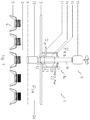
- the device 1 comprises an aseptic zone 2 which at its upper side is delimited by a roof top 3. Bottles 4 are transported with their upper ends through the zone 2 by means of bottle carriers 5. During operation a conditioning medium is supplied into the zone 2 by means of a conditioning medium supply (not shown) connecting to an upper part 2a of the zone 2. A grid plate 6 is provided for equally distributing the conditioning medium throughout the zone 2 over the upper ends of the bottles 4.
- a capping unit 9 On top of the device 1, in an environment outside the conditioned zone 2, a capping unit 9 is mounted.
- the unit 9 comprises a servo drive unit 10 which is able to translate a drive shaft 11 up and down along an y-axis as well as to rotate it around this y-axis, in order to place and screw suitable caps, lids, or the like, on top of the bottles 4.
- the drive shaft 11 at its lower end is provided with an operating organ 12 which is connectable to a chuck 13 present inside the conditioned zone 2.
- the drive shaft 11 extends through a decontamination box 14 which comprises an outer suction chamber 15 and an inner sterilization chamber 16.
- the sterilization chamber 16 lies fully inside the suction chamber 15 and as it where is enclosed/encompassed by it.
- a sterilization medium supply 17 is connected to the sterilization chamber 16.
- the sterilization medium supply 17 is connected to a reservoir from out of which sterilization medium can be supplied, for example by means of a pump, at a pressure Pin, into the sterilization chamber 16.
- the drive shaft 11 partly extends through the sterilization chamber 16.
- first and second outflow gaps 20, 21 are provided leading into the suction chamber 15.
- the gaps 20, 21 are each formed by a play left free in between walls delimiting feed-through openings in the sterilization chamber 16 and an outer circumferential wall of the drive shaft 11.
- the suction chamber 15 is equipped with a media discharge 22.
- the media discharge 22 is connected to a reservoir towards which media sucked out of the chamber 15 can be transported, for example by means of a pump, at a pressure Pout, out into the discharge 22.
- the drive shaft 11 also partly extends through the suction chamber 15.
- inner and outer inflow gaps 24, 25 are provided leading into the suction chamber 15.
- the gaps 24, 25 are each formed by a play left free in between walls delimiting feed-through openings in the suction chamber 15/roof top 3 and an outer circumferential wall of the drive shaft 11.
- the supplying pressure Pin of the sterilization medium supplied to the sterilization chamber 16 preferably is controlled such that it is higher than the discharging pressure Pout of the media sucked out of the suction chamber 15. Furthermore, during operation, the discharging pressure Pout of the media sucked out of the suction chamber 15 preferably is controlled such that it is lower than the supplying pressure Pc.m. of the conditioning medium supplied to the conditioned zone 2. Furthermore, during operation, the discharging pressure Pout of the media sucked out of the suction chamber 15 preferably is controlled such that it is lower than the pressure Pe.a. of the environmental air surrounding the device 1. For regulating those aimed pressure differences: Pin > Pout Pout ⁇ Pc . m . Pout ⁇ Pe . a . a control unit can be provided for steering respective valves, pumps, and the like connecting to the various media supplies and discharges.
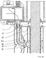
- flow patterns of the various media occur as indicated in fig. 1 .
- the sterilization medium distributes itself inside the chamber 16, from there starts to flow along the shaft 11, then flows via the gaps 20, 21 out of the chamber 16 into the chamber 15, where it is mixed with some conditioning medium flowing via the gap 24 out of the conditioned zone 2 into the chamber 15, and where it is mixed with some environmental air flowing via the gap 25 out of the environment into the chamber 15.
- This mixture of the three respective media then flows out of the chamber 15 via the discharge 22.
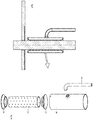
- Each sterilization chamber 16 at its outer side is delimited by a cylindrical bushing 30. Inside the bushing 30 a distribution tube 31 is placed. See fig. 3a . Between the bushing 30 and the tube 31 a distribution space 32 is present. The supply 17 connects to this space 32.
- the tube 31 is formed by a perforated body, each perforation forming an opening for sterilization medium to flow through towards the drive shaft 11. The dimensions of the openings can be varied, and for example be made larger the further away they lie from the supply 17.
- the tube 31 is held centred inside the bushing 30 by means of two curved end rings 33.
- the curved shape of the rings 33 helps to smoothly guide the sterilization medium flowing out of the chamber 16 into the chamber 15.
- curved flow guides 35 are provided at outer sides of the bushing 30 and leading towards the common media discharge 22.
- the distribution tube 31 fits with a play of preferably a few millimetres, and for example be about 3 millimetres, around the drive shaft 11.
- the gaps 20, 21, 24, 25 have been given similar smallest width dimensions of a few millimetres. Together the defined play and gaps create equal flows along the drive shaft 11.
- the diameter of the openings inside the tube 31, preferably is a few millimetres, and can for example be about 2 millimetres. This may help to create a minor overpressure of a few Pa, for example about 3Pa, in the bushing 30 in order to have an equal projection and distribution of the sterilization medium onto and over the surface of the shaft 11.
- the sterilization medium can be brought in via the sterilization medium supply by using a manifold to maintain a certain flow rate of for example about 175 Nm3/hr (flow I).
- the sterilization medium is distributed inside the bushing (flow II).
- flow III By causing an overpressure in this bushing and the perforated tube, an equal distribution of the sterilization medium over the surface of the shaft is created (flow III).
- the sterilization medium After having sterilized the surface of the shaft, the sterilization medium is being exhausted by an under pressure in the suction chamber (flow IV). The under pressure also creates a flow out of the conditioned zone (flow V) to make sure no organisms enter the conditioned zone.
- a flow through a top plate of the suction chamber along the drive shafts prevents the mixture of the sterilization and conditioning media getting in the environment (flow V').
- the different flows IV, V, IV' and V' are all led by the flow guides in the direction of the common discharge and there are exhausted due to under pressure in this central discharge (VII).
- the sterilization medium can be the same as the conditioning medium and for example be HPV.
- the media may also be different from each other.
- the amounts, speeds and pressures of the media supplied can be increased or decreased depending on the circumstances and depending on a required level of sterilization.
- the suction chamber being positioned directly adjacent the conditioned zone, it is also possible to provide some kind of distancing organ there between.
- the pressure inside the suction chamber somewhat higher than the environmental pressure.
- the invention provides a relative simple, economic and user-friendly decontamination box provision for operating means of a container filling and/or closing device with which high levels of sterility up to aseptic conditions, can easily be obtained even for operating systems which have to perform somewhat more complex operations like combinations of translational and rotational movements.
Landscapes
- Engineering & Computer Science (AREA)
- Mechanical Engineering (AREA)
- Filling Of Jars Or Cans And Processes For Cleaning And Sealing Jars (AREA)
- Apparatus For Disinfection Or Sterilisation (AREA)
Applications Claiming Priority (2)
| Application Number | Priority Date | Filing Date | Title |
|---|---|---|---|
| NL2013735A NL2013735B1 (en) | 2014-11-04 | 2014-11-04 | Device for the filling and/or closing of containers having a drive shaft decontamination box. |
| PCT/NL2015/050763 WO2016072847A1 (en) | 2014-11-04 | 2015-11-02 | Device for the filling and/or closing of containers having a drive shaft decontamination box. |
Publications (2)
| Publication Number | Publication Date |
|---|---|
| EP3215424A1 EP3215424A1 (en) | 2017-09-13 |
| EP3215424B1 true EP3215424B1 (en) | 2018-10-31 |
Family
ID=52472497
Family Applications (1)
| Application Number | Title | Priority Date | Filing Date |
|---|---|---|---|
| EP15820318.2A Active EP3215424B1 (en) | 2014-11-04 | 2015-11-02 | Device for the filling and/or closing of containers having a drive shaft decontamination box. |
Country Status (8)
| Country | Link |
|---|---|
| US (1) | US10494128B2 (OSRAM) |
| EP (1) | EP3215424B1 (OSRAM) |
| JP (1) | JP6660956B2 (OSRAM) |
| CN (1) | CN107000873B (OSRAM) |
| BR (1) | BR112017009273B1 (OSRAM) |
| CA (1) | CA2965613C (OSRAM) |
| NL (1) | NL2013735B1 (OSRAM) |
| WO (1) | WO2016072847A1 (OSRAM) |
Families Citing this family (5)
| Publication number | Priority date | Publication date | Assignee | Title |
|---|---|---|---|---|
| DE102015112790A1 (de) * | 2015-08-04 | 2017-02-09 | Khs Gmbh | Verfahren zur Reinigung und/oder Desinfektion von Verschließelementen einer Verschließmaschine, Verschließmaschine sowie Verschließelement |
| IT201700084319A1 (it) * | 2017-07-24 | 2019-01-24 | Arol Spa | Dispositivo di guida a cuscino d’aria |
| CN107555368B (zh) * | 2017-08-10 | 2020-02-07 | 苏州首达机械有限公司 | 抓取旋盖二合一装置 |
| CN113428595B (zh) * | 2021-07-30 | 2023-05-09 | 山东新华医疗器械股份有限公司 | 一种转运区域及其无菌小车转运装置 |
| CN114558156B (zh) * | 2022-03-08 | 2024-12-10 | 杭州中亚机械股份有限公司 | 一种瓶坯灭菌装置 |
Family Cites Families (9)
| Publication number | Priority date | Publication date | Assignee | Title |
|---|---|---|---|---|
| CH539397A (de) | 1971-09-28 | 1973-07-31 | Hero Conserven | Anlage zum Sterilisieren von mit Gut, insbesondere mit Lebens- oder Genussmitteln, gefüllten Packungen |
| DE4038889A1 (de) | 1990-02-02 | 1991-08-14 | Hamba Maschf | Becherfuellwerk fuer nahrungs- und genussmittel, insbesondere fuer molkereiprodukte |
| DE10004076C1 (de) | 2000-01-31 | 2001-06-21 | Hassia Verpackung Ag | Steriltunnel für aseptisch arbeitende Verpackungsmaschinen |
| JP2003102809A (ja) | 2001-09-28 | 2003-04-08 | Hisaka Works Ltd | レトルト殺菌・滅菌機における品物容器の搬入搬出駆動装置 |
| JP4182280B2 (ja) * | 2002-06-07 | 2008-11-19 | 四国化工機株式会社 | ロータリ式無菌充填装置 |
| JP4265302B2 (ja) * | 2003-06-23 | 2009-05-20 | 大日本印刷株式会社 | 無菌充填装置 |
| DE102005032322A1 (de) * | 2005-07-08 | 2007-01-11 | Sig Technology Ag | Verfahren und Maschine zum Verschließen von Flaschen mit sterilen Kappen |
| JP4940944B2 (ja) | 2006-12-28 | 2012-05-30 | 澁谷工業株式会社 | 容器充填システム |
| CN104083781B (zh) | 2014-07-21 | 2016-04-13 | 山东新华医疗器械股份有限公司 | 一种蒸汽灭菌器的灭菌方法及蒸汽灭菌器 |
-
2014
- 2014-11-04 NL NL2013735A patent/NL2013735B1/en active
-
2015
- 2015-11-02 EP EP15820318.2A patent/EP3215424B1/en active Active
- 2015-11-02 CN CN201580058937.7A patent/CN107000873B/zh active Active
- 2015-11-02 WO PCT/NL2015/050763 patent/WO2016072847A1/en not_active Ceased
- 2015-11-02 US US15/524,563 patent/US10494128B2/en active Active
- 2015-11-02 BR BR112017009273-5A patent/BR112017009273B1/pt active IP Right Grant
- 2015-11-02 CA CA2965613A patent/CA2965613C/en active Active
- 2015-11-02 JP JP2017544267A patent/JP6660956B2/ja active Active
Non-Patent Citations (1)
| Title |
|---|
| None * |
Also Published As
| Publication number | Publication date |
|---|---|
| CN107000873B (zh) | 2019-07-16 |
| CA2965613A1 (en) | 2016-05-12 |
| US10494128B2 (en) | 2019-12-03 |
| WO2016072847A1 (en) | 2016-05-12 |
| JP2017533870A (ja) | 2017-11-16 |
| BR112017009273B1 (pt) | 2021-02-17 |
| BR112017009273A2 (pt) | 2018-01-30 |
| EP3215424A1 (en) | 2017-09-13 |
| CA2965613C (en) | 2023-01-24 |
| NL2013735B1 (en) | 2016-10-04 |
| JP6660956B2 (ja) | 2020-03-11 |
| CN107000873A (zh) | 2017-08-01 |
| US20180170601A1 (en) | 2018-06-21 |
Similar Documents
| Publication | Publication Date | Title |
|---|---|---|
| EP3215424B1 (en) | Device for the filling and/or closing of containers having a drive shaft decontamination box. | |
| US5848515A (en) | Continuous-cycle sterile bottling plant | |
| ES2542896T3 (es) | Aparato para formar recipientes asépticos | |
| CN101081687B (zh) | 密封机器元件间过渡部的密封组件及有该密封组件的设备 | |
| JP4235617B2 (ja) | 無菌状態で容器を取扱う瓶詰めシステムの構成装置 | |
| US8857478B2 (en) | Apparatus for treating containers having a height-adjustable isolator | |
| US20120210673A1 (en) | Container Treatment System Having an Aseptic Wall Duct | |
| US8596030B2 (en) | Closing device for containers having a sterile space | |
| DE60202995T2 (de) | Maschine zum aseptischen Abfüllen | |
| ITMO950120A1 (it) | Impianto di imbottigliamento asettico in continuo | |
| JP4700072B2 (ja) | 無菌バッファ領域を備えた無菌パッケージ化設備 | |
| US20140360624A1 (en) | Filler element and filling system | |
| US8652414B2 (en) | Device for sterilising containers | |
| US20180222738A1 (en) | Device for filling containers with a filling product | |
| US9284173B2 (en) | Filling machine and method for controlling a filling machine | |
| US8776482B2 (en) | Container treatment machine with a passage for passing | |
| JP5763061B2 (ja) | 連結された2空間の間にガス流バリヤを保持する装置および方法 | |
| US5069366A (en) | Aseptic volumetric packaging apparatus | |
| US20120317924A1 (en) | Aseptic packaging installation having aseptic buffer zones | |
| CA2143575C (en) | Device for sterile filling of containers | |
| US20110253258A1 (en) | Container-handling machine | |
| US10173880B2 (en) | Filling system for filling bottles or similar containers | |
| US20210354970A1 (en) | Apparatus and method for treating containers | |
| US20120216906A1 (en) | Method and filling system for filling containers in a pressurized manner |
Legal Events
| Date | Code | Title | Description |
|---|---|---|---|
| PUAI | Public reference made under article 153(3) epc to a published international application that has entered the european phase |
Free format text: ORIGINAL CODE: 0009012 |
|
| 17P | Request for examination filed |
Effective date: 20170602 |
|
| AK | Designated contracting states |
Kind code of ref document: A1 Designated state(s): AL AT BE BG CH CY CZ DE DK EE ES FI FR GB GR HR HU IE IS IT LI LT LU LV MC MK MT NL NO PL PT RO RS SE SI SK SM TR |
|
| AX | Request for extension of the european patent |
Extension state: BA ME |
|
| DAV | Request for validation of the european patent (deleted) | ||
| DAX | Request for extension of the european patent (deleted) | ||
| RAP1 | Party data changed (applicant data changed or rights of an application transferred) |
Owner name: JBT FOOD & DAIRY SYSTEMS B.V. |
|
| GRAP | Despatch of communication of intention to grant a patent |
Free format text: ORIGINAL CODE: EPIDOSNIGR1 |
|
| RIC1 | Information provided on ipc code assigned before grant |
Ipc: B65B 55/10 20060101ALI20180430BHEP Ipc: B65B 55/02 20060101AFI20180430BHEP Ipc: B67C 3/22 20060101ALI20180430BHEP Ipc: B65B 7/28 20060101ALI20180430BHEP Ipc: B67B 3/20 20060101ALI20180430BHEP |
|
| INTG | Intention to grant announced |
Effective date: 20180531 |
|
| GRAS | Grant fee paid |
Free format text: ORIGINAL CODE: EPIDOSNIGR3 |
|
| GRAA | (expected) grant |
Free format text: ORIGINAL CODE: 0009210 |
|
| AK | Designated contracting states |
Kind code of ref document: B1 Designated state(s): AL AT BE BG CH CY CZ DE DK EE ES FI FR GB GR HR HU IE IS IT LI LT LU LV MC MK MT NL NO PL PT RO RS SE SI SK SM TR |
|
| REG | Reference to a national code |
Ref country code: CH Ref legal event code: EP Ref country code: GB Ref legal event code: FG4D |
|
| REG | Reference to a national code |
Ref country code: AT Ref legal event code: REF Ref document number: 1059082 Country of ref document: AT Kind code of ref document: T Effective date: 20181115 |
|
| REG | Reference to a national code |
Ref country code: DE Ref legal event code: R096 Ref document number: 602015019293 Country of ref document: DE |
|
| REG | Reference to a national code |
Ref country code: IE Ref legal event code: FG4D |
|
| REG | Reference to a national code |
Ref country code: NL Ref legal event code: MP Effective date: 20181031 |
|
| REG | Reference to a national code |
Ref country code: LT Ref legal event code: MG4D |
|
| REG | Reference to a national code |
Ref country code: AT Ref legal event code: MK05 Ref document number: 1059082 Country of ref document: AT Kind code of ref document: T Effective date: 20181031 |
|
| PG25 | Lapsed in a contracting state [announced via postgrant information from national office to epo] |
Ref country code: ES Free format text: LAPSE BECAUSE OF FAILURE TO SUBMIT A TRANSLATION OF THE DESCRIPTION OR TO PAY THE FEE WITHIN THE PRESCRIBED TIME-LIMIT Effective date: 20181031 Ref country code: IS Free format text: LAPSE BECAUSE OF FAILURE TO SUBMIT A TRANSLATION OF THE DESCRIPTION OR TO PAY THE FEE WITHIN THE PRESCRIBED TIME-LIMIT Effective date: 20190228 Ref country code: AT Free format text: LAPSE BECAUSE OF FAILURE TO SUBMIT A TRANSLATION OF THE DESCRIPTION OR TO PAY THE FEE WITHIN THE PRESCRIBED TIME-LIMIT Effective date: 20181031 Ref country code: LV Free format text: LAPSE BECAUSE OF FAILURE TO SUBMIT A TRANSLATION OF THE DESCRIPTION OR TO PAY THE FEE WITHIN THE PRESCRIBED TIME-LIMIT Effective date: 20181031 Ref country code: FI Free format text: LAPSE BECAUSE OF FAILURE TO SUBMIT A TRANSLATION OF THE DESCRIPTION OR TO PAY THE FEE WITHIN THE PRESCRIBED TIME-LIMIT Effective date: 20181031 Ref country code: BG Free format text: LAPSE BECAUSE OF FAILURE TO SUBMIT A TRANSLATION OF THE DESCRIPTION OR TO PAY THE FEE WITHIN THE PRESCRIBED TIME-LIMIT Effective date: 20190131 Ref country code: PL Free format text: LAPSE BECAUSE OF FAILURE TO SUBMIT A TRANSLATION OF THE DESCRIPTION OR TO PAY THE FEE WITHIN THE PRESCRIBED TIME-LIMIT Effective date: 20181031 Ref country code: HR Free format text: LAPSE BECAUSE OF FAILURE TO SUBMIT A TRANSLATION OF THE DESCRIPTION OR TO PAY THE FEE WITHIN THE PRESCRIBED TIME-LIMIT Effective date: 20181031 Ref country code: NO Free format text: LAPSE BECAUSE OF FAILURE TO SUBMIT A TRANSLATION OF THE DESCRIPTION OR TO PAY THE FEE WITHIN THE PRESCRIBED TIME-LIMIT Effective date: 20190131 Ref country code: LT Free format text: LAPSE BECAUSE OF FAILURE TO SUBMIT A TRANSLATION OF THE DESCRIPTION OR TO PAY THE FEE WITHIN THE PRESCRIBED TIME-LIMIT Effective date: 20181031 |
|
| PG25 | Lapsed in a contracting state [announced via postgrant information from national office to epo] |
Ref country code: NL Free format text: LAPSE BECAUSE OF FAILURE TO SUBMIT A TRANSLATION OF THE DESCRIPTION OR TO PAY THE FEE WITHIN THE PRESCRIBED TIME-LIMIT Effective date: 20181031 Ref country code: GR Free format text: LAPSE BECAUSE OF FAILURE TO SUBMIT A TRANSLATION OF THE DESCRIPTION OR TO PAY THE FEE WITHIN THE PRESCRIBED TIME-LIMIT Effective date: 20190201 Ref country code: RS Free format text: LAPSE BECAUSE OF FAILURE TO SUBMIT A TRANSLATION OF THE DESCRIPTION OR TO PAY THE FEE WITHIN THE PRESCRIBED TIME-LIMIT Effective date: 20181031 Ref country code: SE Free format text: LAPSE BECAUSE OF FAILURE TO SUBMIT A TRANSLATION OF THE DESCRIPTION OR TO PAY THE FEE WITHIN THE PRESCRIBED TIME-LIMIT Effective date: 20181031 Ref country code: PT Free format text: LAPSE BECAUSE OF FAILURE TO SUBMIT A TRANSLATION OF THE DESCRIPTION OR TO PAY THE FEE WITHIN THE PRESCRIBED TIME-LIMIT Effective date: 20190301 Ref country code: AL Free format text: LAPSE BECAUSE OF FAILURE TO SUBMIT A TRANSLATION OF THE DESCRIPTION OR TO PAY THE FEE WITHIN THE PRESCRIBED TIME-LIMIT Effective date: 20181031 |
|
| REG | Reference to a national code |
Ref country code: CH Ref legal event code: PL |
|
| PG25 | Lapsed in a contracting state [announced via postgrant information from national office to epo] |
Ref country code: LU Free format text: LAPSE BECAUSE OF NON-PAYMENT OF DUE FEES Effective date: 20181102 Ref country code: CZ Free format text: LAPSE BECAUSE OF FAILURE TO SUBMIT A TRANSLATION OF THE DESCRIPTION OR TO PAY THE FEE WITHIN THE PRESCRIBED TIME-LIMIT Effective date: 20181031 Ref country code: DK Free format text: LAPSE BECAUSE OF FAILURE TO SUBMIT A TRANSLATION OF THE DESCRIPTION OR TO PAY THE FEE WITHIN THE PRESCRIBED TIME-LIMIT Effective date: 20181031 |
|
| REG | Reference to a national code |
Ref country code: DE Ref legal event code: R097 Ref document number: 602015019293 Country of ref document: DE |
|
| REG | Reference to a national code |
Ref country code: BE Ref legal event code: MM Effective date: 20181130 |
|
| REG | Reference to a national code |
Ref country code: IE Ref legal event code: MM4A |
|
| PG25 | Lapsed in a contracting state [announced via postgrant information from national office to epo] |
Ref country code: SK Free format text: LAPSE BECAUSE OF FAILURE TO SUBMIT A TRANSLATION OF THE DESCRIPTION OR TO PAY THE FEE WITHIN THE PRESCRIBED TIME-LIMIT Effective date: 20181031 Ref country code: RO Free format text: LAPSE BECAUSE OF FAILURE TO SUBMIT A TRANSLATION OF THE DESCRIPTION OR TO PAY THE FEE WITHIN THE PRESCRIBED TIME-LIMIT Effective date: 20181031 Ref country code: EE Free format text: LAPSE BECAUSE OF FAILURE TO SUBMIT A TRANSLATION OF THE DESCRIPTION OR TO PAY THE FEE WITHIN THE PRESCRIBED TIME-LIMIT Effective date: 20181031 Ref country code: SM Free format text: LAPSE BECAUSE OF FAILURE TO SUBMIT A TRANSLATION OF THE DESCRIPTION OR TO PAY THE FEE WITHIN THE PRESCRIBED TIME-LIMIT Effective date: 20181031 Ref country code: MC Free format text: LAPSE BECAUSE OF FAILURE TO SUBMIT A TRANSLATION OF THE DESCRIPTION OR TO PAY THE FEE WITHIN THE PRESCRIBED TIME-LIMIT Effective date: 20181031 Ref country code: CH Free format text: LAPSE BECAUSE OF NON-PAYMENT OF DUE FEES Effective date: 20181130 Ref country code: LI Free format text: LAPSE BECAUSE OF NON-PAYMENT OF DUE FEES Effective date: 20181130 |
|
| PLBE | No opposition filed within time limit |
Free format text: ORIGINAL CODE: 0009261 |
|
| STAA | Information on the status of an ep patent application or granted ep patent |
Free format text: STATUS: NO OPPOSITION FILED WITHIN TIME LIMIT |
|
| 26N | No opposition filed |
Effective date: 20190801 |
|
| PG25 | Lapsed in a contracting state [announced via postgrant information from national office to epo] |
Ref country code: IE Free format text: LAPSE BECAUSE OF NON-PAYMENT OF DUE FEES Effective date: 20181102 Ref country code: SI Free format text: LAPSE BECAUSE OF FAILURE TO SUBMIT A TRANSLATION OF THE DESCRIPTION OR TO PAY THE FEE WITHIN THE PRESCRIBED TIME-LIMIT Effective date: 20181031 |
|
| PG25 | Lapsed in a contracting state [announced via postgrant information from national office to epo] |
Ref country code: BE Free format text: LAPSE BECAUSE OF NON-PAYMENT OF DUE FEES Effective date: 20181130 |
|
| PG25 | Lapsed in a contracting state [announced via postgrant information from national office to epo] |
Ref country code: MT Free format text: LAPSE BECAUSE OF NON-PAYMENT OF DUE FEES Effective date: 20181102 |
|
| PG25 | Lapsed in a contracting state [announced via postgrant information from national office to epo] |
Ref country code: TR Free format text: LAPSE BECAUSE OF FAILURE TO SUBMIT A TRANSLATION OF THE DESCRIPTION OR TO PAY THE FEE WITHIN THE PRESCRIBED TIME-LIMIT Effective date: 20181031 |
|
| PG25 | Lapsed in a contracting state [announced via postgrant information from national office to epo] |
Ref country code: MK Free format text: LAPSE BECAUSE OF NON-PAYMENT OF DUE FEES Effective date: 20181031 Ref country code: HU Free format text: LAPSE BECAUSE OF FAILURE TO SUBMIT A TRANSLATION OF THE DESCRIPTION OR TO PAY THE FEE WITHIN THE PRESCRIBED TIME-LIMIT; INVALID AB INITIO Effective date: 20151102 Ref country code: CY Free format text: LAPSE BECAUSE OF FAILURE TO SUBMIT A TRANSLATION OF THE DESCRIPTION OR TO PAY THE FEE WITHIN THE PRESCRIBED TIME-LIMIT Effective date: 20181031 |
|
| GBPC | Gb: european patent ceased through non-payment of renewal fee |
Effective date: 20191102 |
|
| PG25 | Lapsed in a contracting state [announced via postgrant information from national office to epo] |
Ref country code: GB Free format text: LAPSE BECAUSE OF NON-PAYMENT OF DUE FEES Effective date: 20191102 |
|
| P01 | Opt-out of the competence of the unified patent court (upc) registered |
Effective date: 20230526 |
|
| PGFP | Annual fee paid to national office [announced via postgrant information from national office to epo] |
Ref country code: DE Payment date: 20240910 Year of fee payment: 10 |
|
| PGFP | Annual fee paid to national office [announced via postgrant information from national office to epo] |
Ref country code: IT Payment date: 20241010 Year of fee payment: 10 |
|
| PGFP | Annual fee paid to national office [announced via postgrant information from national office to epo] |
Ref country code: FR Payment date: 20250908 Year of fee payment: 11 |