EP3214193A1 - High-strength steel sheet, high-strength hot-dip galvanized steel sheet, high-strength hot-dip aluminum-coated steel sheet, and high-strength electrogalvanized steel sheet, and methods for manufacturing same - Google Patents
High-strength steel sheet, high-strength hot-dip galvanized steel sheet, high-strength hot-dip aluminum-coated steel sheet, and high-strength electrogalvanized steel sheet, and methods for manufacturing same Download PDFInfo
- Publication number
- EP3214193A1 EP3214193A1 EP15853972.6A EP15853972A EP3214193A1 EP 3214193 A1 EP3214193 A1 EP 3214193A1 EP 15853972 A EP15853972 A EP 15853972A EP 3214193 A1 EP3214193 A1 EP 3214193A1
- Authority
- EP
- European Patent Office
- Prior art keywords
- steel sheet
- less
- strength
- content
- steel
- Prior art date
- Legal status (The legal status is an assumption and is not a legal conclusion. Google has not performed a legal analysis and makes no representation as to the accuracy of the status listed.)
- Granted
Links
- 229910000831 Steel Inorganic materials 0.000 title claims abstract description 319
- 239000010959 steel Substances 0.000 title claims abstract description 319
- 238000000034 method Methods 0.000 title claims description 32
- 229910052782 aluminium Inorganic materials 0.000 title claims description 19
- XAGFODPZIPBFFR-UHFFFAOYSA-N aluminium Chemical compound [Al] XAGFODPZIPBFFR-UHFFFAOYSA-N 0.000 title claims description 18
- 238000004519 manufacturing process Methods 0.000 title claims description 18
- 229910001335 Galvanized steel Inorganic materials 0.000 title claims description 10
- 239000008397 galvanized steel Substances 0.000 title claims description 10
- 229910001566 austenite Inorganic materials 0.000 claims abstract description 107
- 230000000717 retained effect Effects 0.000 claims abstract description 101
- 229910000734 martensite Inorganic materials 0.000 claims abstract description 53
- 229910000859 α-Fe Inorganic materials 0.000 claims abstract description 42
- 229910001568 polygonal ferrite Inorganic materials 0.000 claims abstract description 38
- 239000000203 mixture Substances 0.000 claims abstract description 22
- 239000000126 substance Substances 0.000 claims abstract description 21
- 230000009466 transformation Effects 0.000 claims description 66
- 238000005096 rolling process Methods 0.000 claims description 53
- 238000010438 heat treatment Methods 0.000 claims description 33
- 238000005098 hot rolling Methods 0.000 claims description 27
- 238000005097 cold rolling Methods 0.000 claims description 19
- 238000005554 pickling Methods 0.000 claims description 17
- 238000001816 cooling Methods 0.000 claims description 16
- 238000005275 alloying Methods 0.000 claims description 15
- 238000005246 galvanizing Methods 0.000 claims description 15
- 239000011248 coating agent Substances 0.000 claims description 13
- 238000000576 coating method Methods 0.000 claims description 13
- 229910052799 carbon Inorganic materials 0.000 claims description 7
- 229910052804 chromium Inorganic materials 0.000 claims description 6
- 229910052748 manganese Inorganic materials 0.000 claims description 6
- 229910052750 molybdenum Inorganic materials 0.000 claims description 6
- 229910052787 antimony Inorganic materials 0.000 claims description 5
- 229910052802 copper Inorganic materials 0.000 claims description 5
- 229910052759 nickel Inorganic materials 0.000 claims description 5
- 229910052758 niobium Inorganic materials 0.000 claims description 5
- 229910052710 silicon Inorganic materials 0.000 claims description 5
- 229910052718 tin Inorganic materials 0.000 claims description 5
- 239000012535 impurity Substances 0.000 claims description 4
- 229910052742 iron Inorganic materials 0.000 claims description 4
- 229910052715 tantalum Inorganic materials 0.000 claims description 4
- 229910052720 vanadium Inorganic materials 0.000 claims description 4
- 229910052757 nitrogen Inorganic materials 0.000 claims description 3
- 229910052698 phosphorus Inorganic materials 0.000 claims description 2
- 230000000052 comparative effect Effects 0.000 description 31
- 230000000694 effects Effects 0.000 description 23
- 238000000137 annealing Methods 0.000 description 19
- 238000012360 testing method Methods 0.000 description 18
- 230000007423 decrease Effects 0.000 description 10
- 239000010410 layer Substances 0.000 description 9
- 238000005728 strengthening Methods 0.000 description 9
- 239000000463 material Substances 0.000 description 8
- 230000008569 process Effects 0.000 description 8
- XEEYBQQBJWHFJM-UHFFFAOYSA-N iron Substances [Fe] XEEYBQQBJWHFJM-UHFFFAOYSA-N 0.000 description 6
- 230000007547 defect Effects 0.000 description 5
- 239000002244 precipitate Substances 0.000 description 5
- 229910001563 bainite Inorganic materials 0.000 description 4
- 238000005452 bending Methods 0.000 description 4
- 238000001887 electron backscatter diffraction Methods 0.000 description 4
- 230000036244 malformation Effects 0.000 description 4
- 150000001247 metal acetylides Chemical class 0.000 description 4
- 229910045601 alloy Inorganic materials 0.000 description 3
- 239000000956 alloy Substances 0.000 description 3
- 238000005266 casting Methods 0.000 description 3
- 238000009749 continuous casting Methods 0.000 description 3
- 238000005336 cracking Methods 0.000 description 3
- 239000013078 crystal Substances 0.000 description 3
- 230000006866 deterioration Effects 0.000 description 3
- 230000009977 dual effect Effects 0.000 description 3
- 239000000446 fuel Substances 0.000 description 3
- 238000005461 lubrication Methods 0.000 description 3
- 238000005259 measurement Methods 0.000 description 3
- 238000001000 micrograph Methods 0.000 description 3
- 230000003647 oxidation Effects 0.000 description 3
- 238000007254 oxidation reaction Methods 0.000 description 3
- 229910001562 pearlite Inorganic materials 0.000 description 3
- 238000001556 precipitation Methods 0.000 description 3
- 239000000523 sample Substances 0.000 description 3
- 238000005204 segregation Methods 0.000 description 3
- 239000006104 solid solution Substances 0.000 description 3
- 239000002344 surface layer Substances 0.000 description 3
- 238000009864 tensile test Methods 0.000 description 3
- 150000003568 thioethers Chemical class 0.000 description 3
- 239000003981 vehicle Substances 0.000 description 3
- 238000012935 Averaging Methods 0.000 description 2
- HCHKCACWOHOZIP-UHFFFAOYSA-N Zinc Chemical compound [Zn] HCHKCACWOHOZIP-UHFFFAOYSA-N 0.000 description 2
- 238000010521 absorption reaction Methods 0.000 description 2
- 230000002411 adverse Effects 0.000 description 2
- 230000003712 anti-aging effect Effects 0.000 description 2
- 238000005279 austempering Methods 0.000 description 2
- 230000009286 beneficial effect Effects 0.000 description 2
- 230000015572 biosynthetic process Effects 0.000 description 2
- 229910001567 cementite Inorganic materials 0.000 description 2
- 239000010960 cold rolled steel Substances 0.000 description 2
- 238000009826 distribution Methods 0.000 description 2
- 239000012467 final product Substances 0.000 description 2
- KSOKAHYVTMZFBJ-UHFFFAOYSA-N iron;methane Chemical compound C.[Fe].[Fe].[Fe] KSOKAHYVTMZFBJ-UHFFFAOYSA-N 0.000 description 2
- 238000005121 nitriding Methods 0.000 description 2
- 239000000758 substrate Substances 0.000 description 2
- 229910052725 zinc Inorganic materials 0.000 description 2
- 239000011701 zinc Substances 0.000 description 2
- 241000219307 Atriplex rosea Species 0.000 description 1
- 238000002441 X-ray diffraction Methods 0.000 description 1
- 230000002159 abnormal effect Effects 0.000 description 1
- 230000003749 cleanliness Effects 0.000 description 1
- 239000011247 coating layer Substances 0.000 description 1
- 239000012141 concentrate Substances 0.000 description 1
- 238000013016 damping Methods 0.000 description 1
- 238000005262 decarbonization Methods 0.000 description 1
- 238000004090 dissolution Methods 0.000 description 1
- 239000003925 fat Substances 0.000 description 1
- 230000008570 general process Effects 0.000 description 1
- 230000000977 initiatory effect Effects 0.000 description 1
- 238000011835 investigation Methods 0.000 description 1
- 238000005304 joining Methods 0.000 description 1
- 239000003595 mist Substances 0.000 description 1
- 230000000116 mitigating effect Effects 0.000 description 1
- 239000003921 oil Substances 0.000 description 1
- 230000002085 persistent effect Effects 0.000 description 1
- 238000005498 polishing Methods 0.000 description 1
- 230000002035 prolonged effect Effects 0.000 description 1
- 239000011347 resin Substances 0.000 description 1
- 229920005989 resin Polymers 0.000 description 1
- 239000011265 semifinished product Substances 0.000 description 1
- 239000000243 solution Substances 0.000 description 1
- 238000009628 steelmaking Methods 0.000 description 1
- 238000005496 tempering Methods 0.000 description 1
- XLYOFNOQVPJJNP-UHFFFAOYSA-N water Substances O XLYOFNOQVPJJNP-UHFFFAOYSA-N 0.000 description 1
Images
Classifications
-
- C—CHEMISTRY; METALLURGY
- C21—METALLURGY OF IRON
- C21D—MODIFYING THE PHYSICAL STRUCTURE OF FERROUS METALS; GENERAL DEVICES FOR HEAT TREATMENT OF FERROUS OR NON-FERROUS METALS OR ALLOYS; MAKING METAL MALLEABLE, e.g. BY DECARBURISATION OR TEMPERING
- C21D9/00—Heat treatment, e.g. annealing, hardening, quenching or tempering, adapted for particular articles; Furnaces therefor
- C21D9/46—Heat treatment, e.g. annealing, hardening, quenching or tempering, adapted for particular articles; Furnaces therefor for sheet metals
-
- B—PERFORMING OPERATIONS; TRANSPORTING
- B32—LAYERED PRODUCTS
- B32B—LAYERED PRODUCTS, i.e. PRODUCTS BUILT-UP OF STRATA OF FLAT OR NON-FLAT, e.g. CELLULAR OR HONEYCOMB, FORM
- B32B15/00—Layered products comprising a layer of metal
- B32B15/01—Layered products comprising a layer of metal all layers being exclusively metallic
- B32B15/012—Layered products comprising a layer of metal all layers being exclusively metallic one layer being formed of an iron alloy or steel, another layer being formed of aluminium or an aluminium alloy
-
- B—PERFORMING OPERATIONS; TRANSPORTING
- B32—LAYERED PRODUCTS
- B32B—LAYERED PRODUCTS, i.e. PRODUCTS BUILT-UP OF STRATA OF FLAT OR NON-FLAT, e.g. CELLULAR OR HONEYCOMB, FORM
- B32B15/00—Layered products comprising a layer of metal
- B32B15/01—Layered products comprising a layer of metal all layers being exclusively metallic
- B32B15/013—Layered products comprising a layer of metal all layers being exclusively metallic one layer being formed of an iron alloy or steel, another layer being formed of a metal other than iron or aluminium
-
- C—CHEMISTRY; METALLURGY
- C21—METALLURGY OF IRON
- C21D—MODIFYING THE PHYSICAL STRUCTURE OF FERROUS METALS; GENERAL DEVICES FOR HEAT TREATMENT OF FERROUS OR NON-FERROUS METALS OR ALLOYS; MAKING METAL MALLEABLE, e.g. BY DECARBURISATION OR TEMPERING
- C21D6/00—Heat treatment of ferrous alloys
- C21D6/001—Heat treatment of ferrous alloys containing Ni
-
- C—CHEMISTRY; METALLURGY
- C21—METALLURGY OF IRON
- C21D—MODIFYING THE PHYSICAL STRUCTURE OF FERROUS METALS; GENERAL DEVICES FOR HEAT TREATMENT OF FERROUS OR NON-FERROUS METALS OR ALLOYS; MAKING METAL MALLEABLE, e.g. BY DECARBURISATION OR TEMPERING
- C21D6/00—Heat treatment of ferrous alloys
- C21D6/002—Heat treatment of ferrous alloys containing Cr
-
- C—CHEMISTRY; METALLURGY
- C21—METALLURGY OF IRON
- C21D—MODIFYING THE PHYSICAL STRUCTURE OF FERROUS METALS; GENERAL DEVICES FOR HEAT TREATMENT OF FERROUS OR NON-FERROUS METALS OR ALLOYS; MAKING METAL MALLEABLE, e.g. BY DECARBURISATION OR TEMPERING
- C21D6/00—Heat treatment of ferrous alloys
- C21D6/005—Heat treatment of ferrous alloys containing Mn
-
- C—CHEMISTRY; METALLURGY
- C21—METALLURGY OF IRON
- C21D—MODIFYING THE PHYSICAL STRUCTURE OF FERROUS METALS; GENERAL DEVICES FOR HEAT TREATMENT OF FERROUS OR NON-FERROUS METALS OR ALLOYS; MAKING METAL MALLEABLE, e.g. BY DECARBURISATION OR TEMPERING
- C21D6/00—Heat treatment of ferrous alloys
- C21D6/008—Heat treatment of ferrous alloys containing Si
-
- C—CHEMISTRY; METALLURGY
- C21—METALLURGY OF IRON
- C21D—MODIFYING THE PHYSICAL STRUCTURE OF FERROUS METALS; GENERAL DEVICES FOR HEAT TREATMENT OF FERROUS OR NON-FERROUS METALS OR ALLOYS; MAKING METAL MALLEABLE, e.g. BY DECARBURISATION OR TEMPERING
- C21D8/00—Modifying the physical properties by deformation combined with, or followed by, heat treatment
- C21D8/02—Modifying the physical properties by deformation combined with, or followed by, heat treatment during manufacturing of plates or strips
- C21D8/0205—Modifying the physical properties by deformation combined with, or followed by, heat treatment during manufacturing of plates or strips of ferrous alloys
-
- C—CHEMISTRY; METALLURGY
- C21—METALLURGY OF IRON
- C21D—MODIFYING THE PHYSICAL STRUCTURE OF FERROUS METALS; GENERAL DEVICES FOR HEAT TREATMENT OF FERROUS OR NON-FERROUS METALS OR ALLOYS; MAKING METAL MALLEABLE, e.g. BY DECARBURISATION OR TEMPERING
- C21D8/00—Modifying the physical properties by deformation combined with, or followed by, heat treatment
- C21D8/02—Modifying the physical properties by deformation combined with, or followed by, heat treatment during manufacturing of plates or strips
- C21D8/0221—Modifying the physical properties by deformation combined with, or followed by, heat treatment during manufacturing of plates or strips characterised by the working steps
- C21D8/0226—Hot rolling
-
- C—CHEMISTRY; METALLURGY
- C21—METALLURGY OF IRON
- C21D—MODIFYING THE PHYSICAL STRUCTURE OF FERROUS METALS; GENERAL DEVICES FOR HEAT TREATMENT OF FERROUS OR NON-FERROUS METALS OR ALLOYS; MAKING METAL MALLEABLE, e.g. BY DECARBURISATION OR TEMPERING
- C21D8/00—Modifying the physical properties by deformation combined with, or followed by, heat treatment
- C21D8/02—Modifying the physical properties by deformation combined with, or followed by, heat treatment during manufacturing of plates or strips
- C21D8/0221—Modifying the physical properties by deformation combined with, or followed by, heat treatment during manufacturing of plates or strips characterised by the working steps
- C21D8/0236—Cold rolling
-
- C—CHEMISTRY; METALLURGY
- C21—METALLURGY OF IRON
- C21D—MODIFYING THE PHYSICAL STRUCTURE OF FERROUS METALS; GENERAL DEVICES FOR HEAT TREATMENT OF FERROUS OR NON-FERROUS METALS OR ALLOYS; MAKING METAL MALLEABLE, e.g. BY DECARBURISATION OR TEMPERING
- C21D8/00—Modifying the physical properties by deformation combined with, or followed by, heat treatment
- C21D8/02—Modifying the physical properties by deformation combined with, or followed by, heat treatment during manufacturing of plates or strips
- C21D8/0247—Modifying the physical properties by deformation combined with, or followed by, heat treatment during manufacturing of plates or strips characterised by the heat treatment
- C21D8/0263—Modifying the physical properties by deformation combined with, or followed by, heat treatment during manufacturing of plates or strips characterised by the heat treatment following hot rolling
-
- C—CHEMISTRY; METALLURGY
- C21—METALLURGY OF IRON
- C21D—MODIFYING THE PHYSICAL STRUCTURE OF FERROUS METALS; GENERAL DEVICES FOR HEAT TREATMENT OF FERROUS OR NON-FERROUS METALS OR ALLOYS; MAKING METAL MALLEABLE, e.g. BY DECARBURISATION OR TEMPERING
- C21D8/00—Modifying the physical properties by deformation combined with, or followed by, heat treatment
- C21D8/02—Modifying the physical properties by deformation combined with, or followed by, heat treatment during manufacturing of plates or strips
- C21D8/0247—Modifying the physical properties by deformation combined with, or followed by, heat treatment during manufacturing of plates or strips characterised by the heat treatment
- C21D8/0273—Final recrystallisation annealing
-
- C—CHEMISTRY; METALLURGY
- C22—METALLURGY; FERROUS OR NON-FERROUS ALLOYS; TREATMENT OF ALLOYS OR NON-FERROUS METALS
- C22C—ALLOYS
- C22C38/00—Ferrous alloys, e.g. steel alloys
-
- C—CHEMISTRY; METALLURGY
- C22—METALLURGY; FERROUS OR NON-FERROUS ALLOYS; TREATMENT OF ALLOYS OR NON-FERROUS METALS
- C22C—ALLOYS
- C22C38/00—Ferrous alloys, e.g. steel alloys
- C22C38/001—Ferrous alloys, e.g. steel alloys containing N
-
- C—CHEMISTRY; METALLURGY
- C22—METALLURGY; FERROUS OR NON-FERROUS ALLOYS; TREATMENT OF ALLOYS OR NON-FERROUS METALS
- C22C—ALLOYS
- C22C38/00—Ferrous alloys, e.g. steel alloys
- C22C38/002—Ferrous alloys, e.g. steel alloys containing In, Mg, or other elements not provided for in one single group C22C38/001 - C22C38/60
-
- C—CHEMISTRY; METALLURGY
- C22—METALLURGY; FERROUS OR NON-FERROUS ALLOYS; TREATMENT OF ALLOYS OR NON-FERROUS METALS
- C22C—ALLOYS
- C22C38/00—Ferrous alloys, e.g. steel alloys
- C22C38/005—Ferrous alloys, e.g. steel alloys containing rare earths, i.e. Sc, Y, Lanthanides
-
- C—CHEMISTRY; METALLURGY
- C22—METALLURGY; FERROUS OR NON-FERROUS ALLOYS; TREATMENT OF ALLOYS OR NON-FERROUS METALS
- C22C—ALLOYS
- C22C38/00—Ferrous alloys, e.g. steel alloys
- C22C38/008—Ferrous alloys, e.g. steel alloys containing tin
-
- C—CHEMISTRY; METALLURGY
- C22—METALLURGY; FERROUS OR NON-FERROUS ALLOYS; TREATMENT OF ALLOYS OR NON-FERROUS METALS
- C22C—ALLOYS
- C22C38/00—Ferrous alloys, e.g. steel alloys
- C22C38/02—Ferrous alloys, e.g. steel alloys containing silicon
-
- C—CHEMISTRY; METALLURGY
- C22—METALLURGY; FERROUS OR NON-FERROUS ALLOYS; TREATMENT OF ALLOYS OR NON-FERROUS METALS
- C22C—ALLOYS
- C22C38/00—Ferrous alloys, e.g. steel alloys
- C22C38/04—Ferrous alloys, e.g. steel alloys containing manganese
-
- C—CHEMISTRY; METALLURGY
- C22—METALLURGY; FERROUS OR NON-FERROUS ALLOYS; TREATMENT OF ALLOYS OR NON-FERROUS METALS
- C22C—ALLOYS
- C22C38/00—Ferrous alloys, e.g. steel alloys
- C22C38/06—Ferrous alloys, e.g. steel alloys containing aluminium
-
- C—CHEMISTRY; METALLURGY
- C22—METALLURGY; FERROUS OR NON-FERROUS ALLOYS; TREATMENT OF ALLOYS OR NON-FERROUS METALS
- C22C—ALLOYS
- C22C38/00—Ferrous alloys, e.g. steel alloys
- C22C38/08—Ferrous alloys, e.g. steel alloys containing nickel
-
- C—CHEMISTRY; METALLURGY
- C22—METALLURGY; FERROUS OR NON-FERROUS ALLOYS; TREATMENT OF ALLOYS OR NON-FERROUS METALS
- C22C—ALLOYS
- C22C38/00—Ferrous alloys, e.g. steel alloys
- C22C38/12—Ferrous alloys, e.g. steel alloys containing tungsten, tantalum, molybdenum, vanadium, or niobium
-
- C—CHEMISTRY; METALLURGY
- C22—METALLURGY; FERROUS OR NON-FERROUS ALLOYS; TREATMENT OF ALLOYS OR NON-FERROUS METALS
- C22C—ALLOYS
- C22C38/00—Ferrous alloys, e.g. steel alloys
- C22C38/14—Ferrous alloys, e.g. steel alloys containing titanium or zirconium
-
- C—CHEMISTRY; METALLURGY
- C22—METALLURGY; FERROUS OR NON-FERROUS ALLOYS; TREATMENT OF ALLOYS OR NON-FERROUS METALS
- C22C—ALLOYS
- C22C38/00—Ferrous alloys, e.g. steel alloys
- C22C38/16—Ferrous alloys, e.g. steel alloys containing copper
-
- C—CHEMISTRY; METALLURGY
- C22—METALLURGY; FERROUS OR NON-FERROUS ALLOYS; TREATMENT OF ALLOYS OR NON-FERROUS METALS
- C22C—ALLOYS
- C22C38/00—Ferrous alloys, e.g. steel alloys
- C22C38/18—Ferrous alloys, e.g. steel alloys containing chromium
- C22C38/28—Ferrous alloys, e.g. steel alloys containing chromium with titanium or zirconium
-
- C—CHEMISTRY; METALLURGY
- C22—METALLURGY; FERROUS OR NON-FERROUS ALLOYS; TREATMENT OF ALLOYS OR NON-FERROUS METALS
- C22C—ALLOYS
- C22C38/00—Ferrous alloys, e.g. steel alloys
- C22C38/18—Ferrous alloys, e.g. steel alloys containing chromium
- C22C38/38—Ferrous alloys, e.g. steel alloys containing chromium with more than 1.5% by weight of manganese
-
- C—CHEMISTRY; METALLURGY
- C22—METALLURGY; FERROUS OR NON-FERROUS ALLOYS; TREATMENT OF ALLOYS OR NON-FERROUS METALS
- C22C—ALLOYS
- C22C38/00—Ferrous alloys, e.g. steel alloys
- C22C38/18—Ferrous alloys, e.g. steel alloys containing chromium
- C22C38/40—Ferrous alloys, e.g. steel alloys containing chromium with nickel
- C22C38/58—Ferrous alloys, e.g. steel alloys containing chromium with nickel with more than 1.5% by weight of manganese
-
- C—CHEMISTRY; METALLURGY
- C22—METALLURGY; FERROUS OR NON-FERROUS ALLOYS; TREATMENT OF ALLOYS OR NON-FERROUS METALS
- C22C—ALLOYS
- C22C38/00—Ferrous alloys, e.g. steel alloys
- C22C38/60—Ferrous alloys, e.g. steel alloys containing lead, selenium, tellurium, or antimony, or more than 0.04% by weight of sulfur
-
- C—CHEMISTRY; METALLURGY
- C23—COATING METALLIC MATERIAL; COATING MATERIAL WITH METALLIC MATERIAL; CHEMICAL SURFACE TREATMENT; DIFFUSION TREATMENT OF METALLIC MATERIAL; COATING BY VACUUM EVAPORATION, BY SPUTTERING, BY ION IMPLANTATION OR BY CHEMICAL VAPOUR DEPOSITION, IN GENERAL; INHIBITING CORROSION OF METALLIC MATERIAL OR INCRUSTATION IN GENERAL
- C23C—COATING METALLIC MATERIAL; COATING MATERIAL WITH METALLIC MATERIAL; SURFACE TREATMENT OF METALLIC MATERIAL BY DIFFUSION INTO THE SURFACE, BY CHEMICAL CONVERSION OR SUBSTITUTION; COATING BY VACUUM EVAPORATION, BY SPUTTERING, BY ION IMPLANTATION OR BY CHEMICAL VAPOUR DEPOSITION, IN GENERAL
- C23C2/00—Hot-dipping or immersion processes for applying the coating material in the molten state without affecting the shape; Apparatus therefor
- C23C2/02—Pretreatment of the material to be coated, e.g. for coating on selected surface areas
- C23C2/022—Pretreatment of the material to be coated, e.g. for coating on selected surface areas by heating
- C23C2/0224—Two or more thermal pretreatments
-
- C—CHEMISTRY; METALLURGY
- C23—COATING METALLIC MATERIAL; COATING MATERIAL WITH METALLIC MATERIAL; CHEMICAL SURFACE TREATMENT; DIFFUSION TREATMENT OF METALLIC MATERIAL; COATING BY VACUUM EVAPORATION, BY SPUTTERING, BY ION IMPLANTATION OR BY CHEMICAL VAPOUR DEPOSITION, IN GENERAL; INHIBITING CORROSION OF METALLIC MATERIAL OR INCRUSTATION IN GENERAL
- C23C—COATING METALLIC MATERIAL; COATING MATERIAL WITH METALLIC MATERIAL; SURFACE TREATMENT OF METALLIC MATERIAL BY DIFFUSION INTO THE SURFACE, BY CHEMICAL CONVERSION OR SUBSTITUTION; COATING BY VACUUM EVAPORATION, BY SPUTTERING, BY ION IMPLANTATION OR BY CHEMICAL VAPOUR DEPOSITION, IN GENERAL
- C23C2/00—Hot-dipping or immersion processes for applying the coating material in the molten state without affecting the shape; Apparatus therefor
- C23C2/02—Pretreatment of the material to be coated, e.g. for coating on selected surface areas
- C23C2/024—Pretreatment of the material to be coated, e.g. for coating on selected surface areas by cleaning or etching
-
- C—CHEMISTRY; METALLURGY
- C23—COATING METALLIC MATERIAL; COATING MATERIAL WITH METALLIC MATERIAL; CHEMICAL SURFACE TREATMENT; DIFFUSION TREATMENT OF METALLIC MATERIAL; COATING BY VACUUM EVAPORATION, BY SPUTTERING, BY ION IMPLANTATION OR BY CHEMICAL VAPOUR DEPOSITION, IN GENERAL; INHIBITING CORROSION OF METALLIC MATERIAL OR INCRUSTATION IN GENERAL
- C23C—COATING METALLIC MATERIAL; COATING MATERIAL WITH METALLIC MATERIAL; SURFACE TREATMENT OF METALLIC MATERIAL BY DIFFUSION INTO THE SURFACE, BY CHEMICAL CONVERSION OR SUBSTITUTION; COATING BY VACUUM EVAPORATION, BY SPUTTERING, BY ION IMPLANTATION OR BY CHEMICAL VAPOUR DEPOSITION, IN GENERAL
- C23C2/00—Hot-dipping or immersion processes for applying the coating material in the molten state without affecting the shape; Apparatus therefor
- C23C2/04—Hot-dipping or immersion processes for applying the coating material in the molten state without affecting the shape; Apparatus therefor characterised by the coating material
- C23C2/06—Zinc or cadmium or alloys based thereon
-
- C—CHEMISTRY; METALLURGY
- C23—COATING METALLIC MATERIAL; COATING MATERIAL WITH METALLIC MATERIAL; CHEMICAL SURFACE TREATMENT; DIFFUSION TREATMENT OF METALLIC MATERIAL; COATING BY VACUUM EVAPORATION, BY SPUTTERING, BY ION IMPLANTATION OR BY CHEMICAL VAPOUR DEPOSITION, IN GENERAL; INHIBITING CORROSION OF METALLIC MATERIAL OR INCRUSTATION IN GENERAL
- C23C—COATING METALLIC MATERIAL; COATING MATERIAL WITH METALLIC MATERIAL; SURFACE TREATMENT OF METALLIC MATERIAL BY DIFFUSION INTO THE SURFACE, BY CHEMICAL CONVERSION OR SUBSTITUTION; COATING BY VACUUM EVAPORATION, BY SPUTTERING, BY ION IMPLANTATION OR BY CHEMICAL VAPOUR DEPOSITION, IN GENERAL
- C23C2/00—Hot-dipping or immersion processes for applying the coating material in the molten state without affecting the shape; Apparatus therefor
- C23C2/04—Hot-dipping or immersion processes for applying the coating material in the molten state without affecting the shape; Apparatus therefor characterised by the coating material
- C23C2/12—Aluminium or alloys based thereon
-
- C—CHEMISTRY; METALLURGY
- C23—COATING METALLIC MATERIAL; COATING MATERIAL WITH METALLIC MATERIAL; CHEMICAL SURFACE TREATMENT; DIFFUSION TREATMENT OF METALLIC MATERIAL; COATING BY VACUUM EVAPORATION, BY SPUTTERING, BY ION IMPLANTATION OR BY CHEMICAL VAPOUR DEPOSITION, IN GENERAL; INHIBITING CORROSION OF METALLIC MATERIAL OR INCRUSTATION IN GENERAL
- C23C—COATING METALLIC MATERIAL; COATING MATERIAL WITH METALLIC MATERIAL; SURFACE TREATMENT OF METALLIC MATERIAL BY DIFFUSION INTO THE SURFACE, BY CHEMICAL CONVERSION OR SUBSTITUTION; COATING BY VACUUM EVAPORATION, BY SPUTTERING, BY ION IMPLANTATION OR BY CHEMICAL VAPOUR DEPOSITION, IN GENERAL
- C23C2/00—Hot-dipping or immersion processes for applying the coating material in the molten state without affecting the shape; Apparatus therefor
- C23C2/26—After-treatment
- C23C2/28—Thermal after-treatment, e.g. treatment in oil bath
-
- C—CHEMISTRY; METALLURGY
- C23—COATING METALLIC MATERIAL; COATING MATERIAL WITH METALLIC MATERIAL; CHEMICAL SURFACE TREATMENT; DIFFUSION TREATMENT OF METALLIC MATERIAL; COATING BY VACUUM EVAPORATION, BY SPUTTERING, BY ION IMPLANTATION OR BY CHEMICAL VAPOUR DEPOSITION, IN GENERAL; INHIBITING CORROSION OF METALLIC MATERIAL OR INCRUSTATION IN GENERAL
- C23C—COATING METALLIC MATERIAL; COATING MATERIAL WITH METALLIC MATERIAL; SURFACE TREATMENT OF METALLIC MATERIAL BY DIFFUSION INTO THE SURFACE, BY CHEMICAL CONVERSION OR SUBSTITUTION; COATING BY VACUUM EVAPORATION, BY SPUTTERING, BY ION IMPLANTATION OR BY CHEMICAL VAPOUR DEPOSITION, IN GENERAL
- C23C2/00—Hot-dipping or immersion processes for applying the coating material in the molten state without affecting the shape; Apparatus therefor
- C23C2/34—Hot-dipping or immersion processes for applying the coating material in the molten state without affecting the shape; Apparatus therefor characterised by the shape of the material to be treated
- C23C2/36—Elongated material
- C23C2/40—Plates; Strips
-
- C—CHEMISTRY; METALLURGY
- C23—COATING METALLIC MATERIAL; COATING MATERIAL WITH METALLIC MATERIAL; CHEMICAL SURFACE TREATMENT; DIFFUSION TREATMENT OF METALLIC MATERIAL; COATING BY VACUUM EVAPORATION, BY SPUTTERING, BY ION IMPLANTATION OR BY CHEMICAL VAPOUR DEPOSITION, IN GENERAL; INHIBITING CORROSION OF METALLIC MATERIAL OR INCRUSTATION IN GENERAL
- C23G—CLEANING OR DE-GREASING OF METALLIC MATERIAL BY CHEMICAL METHODS OTHER THAN ELECTROLYSIS
- C23G1/00—Cleaning or pickling metallic material with solutions or molten salts
-
- C—CHEMISTRY; METALLURGY
- C25—ELECTROLYTIC OR ELECTROPHORETIC PROCESSES; APPARATUS THEREFOR
- C25D—PROCESSES FOR THE ELECTROLYTIC OR ELECTROPHORETIC PRODUCTION OF COATINGS; ELECTROFORMING; APPARATUS THEREFOR
- C25D3/00—Electroplating: Baths therefor
- C25D3/02—Electroplating: Baths therefor from solutions
- C25D3/22—Electroplating: Baths therefor from solutions of zinc
-
- C—CHEMISTRY; METALLURGY
- C25—ELECTROLYTIC OR ELECTROPHORETIC PROCESSES; APPARATUS THEREFOR
- C25D—PROCESSES FOR THE ELECTROLYTIC OR ELECTROPHORETIC PRODUCTION OF COATINGS; ELECTROFORMING; APPARATUS THEREFOR
- C25D5/00—Electroplating characterised by the process; Pretreatment or after-treatment of workpieces
- C25D5/34—Pretreatment of metallic surfaces to be electroplated
- C25D5/36—Pretreatment of metallic surfaces to be electroplated of iron or steel
-
- C—CHEMISTRY; METALLURGY
- C25—ELECTROLYTIC OR ELECTROPHORETIC PROCESSES; APPARATUS THEREFOR
- C25D—PROCESSES FOR THE ELECTROLYTIC OR ELECTROPHORETIC PRODUCTION OF COATINGS; ELECTROFORMING; APPARATUS THEREFOR
- C25D5/00—Electroplating characterised by the process; Pretreatment or after-treatment of workpieces
- C25D5/48—After-treatment of electroplated surfaces
- C25D5/50—After-treatment of electroplated surfaces by heat-treatment
-
- C—CHEMISTRY; METALLURGY
- C21—METALLURGY OF IRON
- C21D—MODIFYING THE PHYSICAL STRUCTURE OF FERROUS METALS; GENERAL DEVICES FOR HEAT TREATMENT OF FERROUS OR NON-FERROUS METALS OR ALLOYS; MAKING METAL MALLEABLE, e.g. BY DECARBURISATION OR TEMPERING
- C21D2211/00—Microstructure comprising significant phases
- C21D2211/001—Austenite
-
- C—CHEMISTRY; METALLURGY
- C21—METALLURGY OF IRON
- C21D—MODIFYING THE PHYSICAL STRUCTURE OF FERROUS METALS; GENERAL DEVICES FOR HEAT TREATMENT OF FERROUS OR NON-FERROUS METALS OR ALLOYS; MAKING METAL MALLEABLE, e.g. BY DECARBURISATION OR TEMPERING
- C21D2211/00—Microstructure comprising significant phases
- C21D2211/005—Ferrite
-
- C—CHEMISTRY; METALLURGY
- C21—METALLURGY OF IRON
- C21D—MODIFYING THE PHYSICAL STRUCTURE OF FERROUS METALS; GENERAL DEVICES FOR HEAT TREATMENT OF FERROUS OR NON-FERROUS METALS OR ALLOYS; MAKING METAL MALLEABLE, e.g. BY DECARBURISATION OR TEMPERING
- C21D2211/00—Microstructure comprising significant phases
- C21D2211/008—Martensite
Definitions
- This disclosure relates to a high-strength steel sheet, a high-strength hot-dip galvanized steel sheet, a high-strength hot-dip aluminum-coated steel sheet, and a high-strength electrogalvanized steel sheet, and methods for manufacturing the same, and in particular to, the provision of a steel sheet with excellent formability and high yield ratio that is preferably used in parts in the industrial fields of automobiles, electronics, and the like.
- steel sheets with a tensile strength (TS) of 980 MPa or more are required to have, in particular, enhanced impact energy absorption properties.
- TS tensile strength
- ERR yield ratio
- JPS61157625A proposes a high-strength steel sheet with extremely high ductility having a tensile strength of 1000 MPa or higher and a total elongation (EL) of 30 % or more, utilizing deformation induced transformation of retained austenite.
- JPH1259120A (PTL 2) proposes a high-strength steel sheet with well-balanced strength and ductility that is obtained from high-Mn steel through heat treatment in a ferrite-austenite dual phase region.
- JP2003138345A proposes a high-strength steel sheet with improved local ductility that is obtained from high-Mn steel through hot rolling to have a microstructure containing bainite and martensite after subjection to the hot rolling, followed by annealing and tempering to cause fine retained austenite, and subsequently tempered bainite or tempered martensite in the microstructure.
- the steel sheet described in PTL 1 is manufactured by austenitizing a steel sheet containing C, Si, and Mn as basic components, and subjecting the steel sheet to a so-called austempering process whereby the steel sheet is quenched to and held isothermally in a bainite transformation temperature range. During the austempering process, C concentrates in austenite to form retained austenite.
- PTLs 2 and 3 describes techniques for improving the ductility of steel sheets from the perspective of formability, but do not consider the bendability or yield ratio of the steel sheet.
- a high-strength steel sheet a high-strength hot-dip galvanized steel sheet, a high-strength hot-dip aluminum-coated steel sheet, and a high-strength electrogalvanized steel sheet that are excellent in formability with TS of 980 MPa or more and YR of 68 % or more, and methods for manufacturing the same.
- a steel sheet that has a steel composition containing more than 4.20 mass% and 6.00 mass% or less of Mn, with the addition amounts of other alloying elements such as Ti being adjusted appropriately, is hot rolled to obtain a hot-rolled sheet.
- the hot-rolled sheet is then subjected to pickling to remove scales, retained in a temperature range of Ac 1 transformation temperature + 20 °C to Ac 1 transformation temperature + 120 °C for 600 s to 21,600 s, and cold rolled at a rolling reduction of 30 % or more to obtain a cold-rolled sheet. Further, the cold-rolled sheet is retained in a temperature range of Ac 1 transformation temperature to Ac 1 transformation temperature + 100 °C for 20 s to 900 s, and subsequently cooled.
- the cold-rolled sheet has a microstructure that contains, in area ratio, 15 % or more and 55 % or less of polygonal ferrite, 8 % or more of non-recrystallized ferrite, and 15 % or more and 30 % or less of martensite, where the polygonal ferrite has a mean grain size of 4 ⁇ m or less, the martensite has a mean grain size of 2 ⁇ m or less, and the retained austenite has a mean grain size of 2 ⁇ m or less.
- the microstructure of the cold-rolled sheet can be controlled so that a value obtained by dividing an Mn content in the retained austenite (in mass%) by an Mn content in the polygonal ferrite (in mass%) equals 2.0 or more, making it possible to obtain a volume fraction of 12 % or more of retained austenite stabilized with Mn.
- High-strength steel sheets according to the disclosure are highly beneficial in industrial terms, because they can improve fuel efficiency when applied to, for example, automobile structural parts, by a reduction in the weight of automotive bodies.
- C is an element necessary for causing a low-temperature transformation phase such as martensite to increase strength.
- C is also a useful element for increasing the stability of retained austenite and the ductility of steel. If the C content is less than 0.030 %, it is difficult to ensure a desired area ratio of martensite, and desired strength is not obtained. It is also difficult to guarantee a sufficient volume fraction of retained austenite, and good ductility is not obtained.
- C is excessively added to the steel beyond 0.250 %, hard martensite excessively increases in area ratio, which causes more microvoids at grain boundaries of martensite and facilitates propagation of cracks during bend test and hole expansion test, leading to a reduction in bendability and stretch flangeability.
- the C content is 0.030 % or more and 0.250 % or less.
- the C content is preferably 0.080 % or more.
- the C content is preferably 0.200 % or less.
- Si 0.01 % or more and 3.00 % or less
- Si is an element that improves the strain hardenability of ferrite, and is thus a useful element for ensuring good ductility. If the Si content is below 0.01 %, the addition effect is limited. Thus the lower limit is 0.01 %. On the other hand, excessively adding Si beyond 3.00 % not only embrittles the steel, but also causes red scales or the like to deteriorate surface characteristics. Therefore, the Si content is 0.01 % or more and 3.00 % or less. The Si content is preferably 0.20 % or more. The Si content is preferably 2.00 % or less.
- Mn more than 4.20 % and 6.00 % or less
- Mn is one of the very important elements for the disclosure.
- Mn is an element that stabilizes retained austenite, and is thus a useful element for ensuring good ductility. Mn can also increase the strength of the steel through solid solution strengthening.
- concentration of Mn in retained austenite can ensure obtaining 2 % or more of ⁇ phase with an hcp structure, and furthermore, guarantee the volume fraction of retained austenite being as high as 12 % or more.
- P is an element that has a solid solution strengthening effect and can be added depending on the desired strength. P also facilitates ferrite transformation, and thus is also a useful element for forming a multi-phase structure in the steel sheet. To obtain this effect, the P content in the steel sheet needs to be 0.001 % or more. However, if the P content exceeds 0.100 %, weldability degrades and, when a galvanized layer is subjected to alloying treatment, the alloying rate decreases, impairing galvanizing quality. Therefore, the P content is 0.001 % or more and 0.100 % or less. The P content is preferably 0.005 % or more. The P content is preferably 0.050 % or less.
- the S content is 0.0200 % or less, preferably 0.0100 % or less, and more preferably 0.0050 % or less. Under production constraints, however, the S content is 0.0001 % or more. Therefore, the S content is 0.0001 % or more and 0.0200 % or less. The S content is preferably 0.0001 % or more. The S content is preferably 0.0100 % or less. The S content is more preferably 0.0001 % or more. The S content is more preferably 0.0050 % or less.
- N 0.0005 % or more and 0.0100 % or less
- N is an element that deteriorates the anti-aging property of the steel.
- the deterioration in anti-aging property becomes more pronounced, particularly when the N content exceeds 0.0100 %. Accordingly, smaller N contents are more preferable.
- the N content is 0.0005 % or more. Therefore, the N content is 0.0005 % or more and 0.0100 % or less.
- the N content is preferably 0.0010 % or more.
- the N content is preferably 0.0070 % or less.
- Ti is one of the very important elements for the disclosure. Ti is useful for achieving strengthening by precipitation of the steel. Ti can also ensure a desired area ratio of non-recrystallized ferrite, and contributes to increasing the yield ratio of the steel sheet. Additionally, making use of relatively hard non-recrystallized ferrite, Ti can reduce the difference in hardness from a hard secondary phase (martensite or retained austenite), and also contributes to improving stretch flangeability. These effects can be obtained when the Ti content is 0.005 % or more.
- the Ti content in the steel exceeds 0.200 %, hard martensite excessively increases in area ratio, which causes more microvoids at grain boundaries of martensite and facilitates propagation of cracks during bend test and hole expansion test, leading to a reduction in the bendability and stretch flangeability of the steel sheet. Therefore, the Ti content is 0.005 % or more and 0.200 % or less. The Ti content is preferably 0.010 % or more. The Ti content is preferably 0.100 % or less.
- the chemical composition of the steel may further contain at least one selected from the group consisting of Al: 0.01 % or more and 2.00 % or less, Nb: 0.005 % or more and 0.200 % or less, B: 0.0003 % or more and 0.0050 % or less, Ni: 0.005 % or more and 1.000 % or less, Cr: 0.005 % or more and 1.000 % or less, V: 0.005 % or more and 0.500 % or less, Mo: 0.005 % or more and 1.000 % or less, Cu: 0.005 % or more and 1.000 % or less, Sn: 0.002 % or more and 0.200 % or less, Sb: 0.002 % or more and 0.200 % or less, Ta: 0.001 % or more and 0.010 % or less, Ca: 0.0005 % or more and 0.0050 % or less, Mg: 0.0005 % or more and 0.0050 % or less, and REM: 0.0005
- Al is a useful element for increasing the area of a ferrite-austenite dual phase region and reducing annealing temperature dependency, i.e., increasing the stability of the steel sheet as a material.
- Al acts as a deoxidizer, and is also a useful element for maintaining the cleanliness of the steel. If the Al content is below 0.01 %, however, the addition effect is limited. Thus the lower limit is 0.01 %. On the other hand, excessively adding A1 beyond 2.00 % increases the risk of cracking occurring in a semi-finished product during continuous casting, and inhibits manufacturability. From these perspectives, the Al content is 0.01 % or more and 2.00 % or less. The Al content is preferably 0.20 % or more.
- the A1 content is preferably 1.20 % or less.
- Nb is useful for achieving strengthening by precipitation of the steel.
- the addition effect can be obtained when the content is 0.005 % or more.
- Nb can also ensure a desired area ratio of non-recrystallized ferrite, as in the case of adding Ti, and contributes to increasing the yield ratio of the steel sheet. Additionally, making use of relatively hard non-recrystallized ferrite, Nb can reduce the difference in hardness from a hard secondary phase (martensite or retained austenite), and also contributes to improving stretch flangeability.
- a hard secondary phase martensite or retained austenite
- the Nb content is 0.005 % or more and 0.200 % or less.
- the Nb content is preferably 0.010 % or more.
- the Nb content is preferably 0.100 % or less.
- B may be added as necessary, since it has the effect of suppressing the generation and growth of ferrite from austenite grain boundaries and enables microstructure control according to the circumstances.
- the addition effect can be obtained when the B content is 0.0003 % or more. If the B content exceeds 0.0050 %, however, the formability of the steel sheet degrades. Therefore, when added to steel, the B content is 0.0003 % or more and 0.0050 % or less.
- the B content is preferably 0.0005 % or more.
- the B content is preferably 0.0030 % or less.
- Ni is an element that stabilizes retained austenite, and is thus a useful element for ensuring good ductility, and that increases the strength of the steel through solid solution strengthening.
- the addition effect can be obtained when the Ni content is 0.005 % or more.
- hard martensite excessively increases in area ratio, which causes more microvoids at grain boundaries of martensite and facilitates propagation of cracks during bend test and hole expansion test. This leads to a reduction in the bendability and stretch flangeability of the steel sheet. This also increases cost. Therefore, when added to steel, the Ni content is 0.005 % or more and 1.000 % or less.
- Cr, V, and Mo are elements that may be added as necessary, since they have the effect of improving the balance between strength and ductility.
- the addition effect can be obtained when the Cr content is 0.005 % or more, the V content is 0.005 % or more, and/or the Mo content is 0.005 % or more.
- the Cr content exceeds 1.000 %
- the V content exceeds 0.500 %
- the Mo content exceeds 1.000 %
- hard martensite excessively increases in area ratio, which causes more microvoids at grain boundaries of martensite and facilitates propagation of cracks during bend test and hole expansion test. This leads to a reduction in the bendability and stretch flangeability of the steel sheet, and also causes a rise in cost.
- the Cr content is 0.005 % or more and 1.000 % or less
- the V content is 0.005 % or more and 0.500 % or less
- the Mo content is 0.005 % or more and 1.000 % or less.
- Cu is a useful element for strengthening of steel and may be added for strengthening of steel, as long as the content is within the range disclosed herein.
- the addition effect can be obtained when the Cu content is 0.005 % or more.
- hard martensite excessively increases in area ratio, which causes more microvoids at grain boundaries of martensite and facilitates propagation of cracks during bend test and hole expansion test. This leads to a reduction in the bendability and stretch flangeability of the steel sheet. Therefore, when added to steel, the Cu content is 0.005 % or more and 1.000 % or less.
- Sn and Sb are elements that may be added as necessary from the perspective of suppressing decarbonization of a region extending from the surface layer of the steel sheet to a depth of about several tens of micrometers, which results from nitriding and/or oxidation of the steel sheet surface. Suppressing nitriding and/or oxidation in this way is useful for preventing a reduction in the area ratio of martensite in the steel sheet surface, and for ensuring the TS and stability of the steel sheet as a material. However, excessively adding Sn or Sb beyond 0.200 % reduces toughness. Therefore, when Sn and/or Sb is added to steel, the content of each added element is 0.002 % or more and 0.200 % or less.
- Ta forms alloy carbides or alloy carbonitrides, and contributes to increasing the strength of the steel, as is the case with Ti and Nb. It is also believed that Ta has the effect of effectively suppressing coarsening of precipitates when partially dissolved in Nb carbides or Nb carbonitrides to form complex precipitates, such as (Nb, Ta) (C, N), and providing a stable contribution to increasing the strength of the steel sheet through strengthening by precipitation. Therefore, Ta is preferably added to the steel according to the disclosure. The addition effect of Ta can be obtained when the Ta content is 0.001 % or more. Excessively adding Ta, however, fails to increase the addition effect, but instead results in a rise in alloying cost. Therefore, when added to steel, the Ta content is 0.001 % or more and 0.010 % or less.
- Ca, Mg, and REM are useful elements for causing spheroidization of sulfides and mitigating the adverse effect of sulfides on hole expansion formability (stretch flangeability). To obtain this effect, it is necessary to add any of these elements to steel in an amount of 0.0005 % or more. However, if the content of each added element exceeds 0.0050 %, more inclusions occur, for example, and some defects such as surface defects and internal defects are caused in the steel sheet. Therefore, when Ca, Mg, and/or REM is added to steel, the content of each added element is 0.0005 % or more and 0.0050 % or less.
- the area ratio of polygonal ferrite needs to be 15 % or more to ensure sufficient ductility.
- the area ratio of soft polygonal ferrite needs to be 55 % or less.
- the area ratio of polygonal ferrite is preferably 20 % or more.
- the area ratio of polygonal ferrite is preferably 50 % or less.
- polygonal ferrite refers to ferrite that is relatively soft and that has high ductility.
- non-recrystallized ferrite it is very important to set the area ratio of non-recrystallized ferrite to be 8 % or more.
- non-recrystallized ferrite is useful for increasing the strength of the steel sheet.
- non-recrystallized ferrite may cause a significant decrease in the ductility of the steel sheet, and thus is normally reduced in a general process.
- by using polygonal ferrite and retained austenite to provide good ductility and intentionally utilizing relatively hard non-recrystallized ferrite it is possible to provide the steel sheet with the intended TS, without having to form a large amount of martensite, such as exceeding 30 % in area ratio.
- non-recrystallized ferrite refers to ferrite that contains strain in the grains with a crystal orientation difference of less than 15°, and that is harder than the above-described polygonal ferrite with high ductility.
- no upper limit is placed on the area ratio of non-recrystallized ferrite, yet a preferred upper limit is around 45 %, considering the possibility of increased material anisotropy in the steel sheet surface.
- the area ratio of martensite needs to be 15 % or more.
- the area ratio of martensite needs to be limited to 30 % or less.
- the area ratios of ferrite (including polygonal ferrite and non-recrystallized ferrite) and martensite can be determined in the following way.
- a cross section of a steel sheet that is taken in the sheet thickness direction to be parallel to the rolling direction (which is an L-cross section) is polished, then etched with 3 vol.% nital, and ten locations are observed at 2000 times magnification under an SEM (scanning electron microscope), at a position of sheet thickness x 1/4 (which is the position at a depth of one-fourth of the sheet thickness from the steel sheet surface), to capture microstructure micrographs.
- the captured microstructure micrographs are used to calculate the area ratios of respective phases (ferrite and martensite) for the ten locations using Image-Pro manufactured by Media Cybernetics, the results are averaged, and each average is used as the area ratio of the corresponding phase.
- polygonal ferrite and non-recrystallized ferrite appear as a gray structure (base steel structure), while martensite as a white structure.
- the area ratios of polygonal ferrite and non-recrystallized ferrite can be determined in the following way. Specifically, low-angle grain boundaries in which the crystal orientation difference is from 2° to less than 15° and large-angle grain boundaries in which the crystal orientation difference is 15° or more are identified using EBSD (Electron Backscatter Diffraction). An IQ Map is then created, considering ferrite that contains low-angle grain boundaries in the grains as non-recrystallized ferrite. Then, low-angle grain boundaries and large-angle grain boundaries are extracted from the created IQ Map at ten locations, respectively, to determine the areas of low-angle grain boundaries and large-angle grain boundaries.
- EBSD Electro Backscatter Diffraction
- the areas of polygonal ferrite and non-recrystallized ferrite are calculated to determine the area ratios of polygonal ferrite and non-recrystallized ferrite for the ten locations. By averaging the results, the above-described area ratios of polygonal ferrite and non-recrystallized ferrite are determined.
- volume fraction of retained austenite 12 % or more
- the volume fraction of retained austenite needs to be 12 % or more, preferably 14 % or more, to ensure sufficient ductility.
- a preferred upper limit is around 50 %, considering the risk of formation of increased amounts of unstable retained austenite resulting from insufficient concentration of C, Mn, and the like, which is less effective in improving ductility.
- the volume fraction of retained austenite is calculated by determining the x-ray diffraction intensity of a plane of sheet thickness x 1/4 (which is the plane at a depth of one-fourth of the sheet thickness from the steel sheet surface), which is exposed by polishing the steel sheet surface to a depth of one-fourth of the sheet thickness.
- ⁇ 200 ⁇ , and ⁇ 211 ⁇ planes of ferrite is calculated for all of the twelve combinations, the results are averaged, and the average is used as the volume fraction of retained austenite.
- Mean grain size of polygonal ferrite 4 ⁇ m or less
- polygonal ferrite grains contributes to improving YP and TS.
- polygonal ferrite needs to have a mean grain size of 4 ⁇ m or less, and preferably 3 ⁇ m or less.
- a preferred lower limit is around 0.2 ⁇ m.
- Mean grain size of martensite 2 ⁇ m or less
- the mean grain size of martensite needs to be limited to 2 ⁇ m or less, and preferably to 1.5 ⁇ m or less.
- a preferred lower limit is around 0.05 ⁇ m.
- Mean grain size of retained austenite 2 ⁇ m or less
- the mean grain size of retained austenite needs to be 2 ⁇ m or less, and preferably 1.5 ⁇ m or less.
- a preferred lower limit is around 0.05 ⁇ m.
- the mean grain sizes of polygonal ferrite, martensite, and retained austenite are respectively determined by averaging the results from calculating equivalent circular diameters from the areas of polygonal ferrite grains, martensite grains, and retained austenite grains measured with Image-Pro as mentioned above. Martensite and retained austenite are identified using an EBSD phase map.
- each of the above-described mean grain sizes is determined from the measurements for grains with a grain size of 0.01 ⁇ m or more. The reason is that grains with a grain size of less than 0.01 ⁇ m have no effect on the disclosure.
- the value obtained by dividing the Mn content in the retained austenite (in mass%) by the Mn content in the polygonal ferrite (in mass%) equals 2.0 or more. The reason is that better ductility requires a larger amount of stable retained austenite with concentrated Mn.
- the Mn content in the retained austenite (in mass%) and the Mn content in the polygonal ferrite (in mass%) can be determined in the following way. Specifically, an EPMA (Electron Probe Micro Analyzer) is used to quantify the distribution of Mn in each phase in a cross section along the rolling direction at a position of sheet thickness x 1/4. Then, 30 retained austenite grains and 30 ferrite grains are analyzed to determine Mn contents, the results are averaged, and each average is used as the Mn content in the corresponding phase.
- EPMA Electro Probe Micro Analyzer
- the microstructure according to the disclosure further include carbides ordinarily found in iron and steel sheets, such as granular ferrite, acicular ferrite, bainitic ferrite, tempered martensite, pearlite, and cementite (excluding cementite in pearlite). Any of these structures may be included as long as the area ratio is 10 % or less, without impairing the effect of the disclosure.
- the steel microstructure preferably contains, in area ratio, 2 % or more of ⁇ phase with an hcp structure.
- steel may become brittle when it contains a large amount of ⁇ phase with an hcp structure.
- an appropriate amount of ⁇ phase with an hcp structure is finely distributed within and along boundaries of ferrite and non-recrystallized ferrite grains, it becomes possible to achieve excellent damping performance, while keeping a good balance between strength and ductility.
- Such ⁇ phase with an hcp structure, martensite, and retained austenite can be identified using an EBSD phase map.
- no upper limit is placed on the area ratio of ⁇ phase, yet, in view of the risk of embrittlement of the steel, a preferred upper limit is around 35 %.
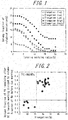
- the working ratio and the quantity of retained austenite showed a tendency as illustrated in FIG. 1 .
- the working ratio refers to the elongation ratio that is determined from a tensile test performed on a JIS No. 5 test piece sampled from a steel sheet with the tensile direction being perpendicular to the rolling direction of the steel sheet. It can be seen from FIG. 1 that the samples with good elongation each showed a gentle decrease in the quantity of retained austenite as the working ratio increased.
- the value obtained by dividing the volume fraction of retained austenite remaining in a steel after subjection to tensile working with an elongation value of 10 % by the volume fraction of retained austenite before the tensile working equals 0.3 or more. The reason is that this set up may ensure the transformation of sufficient retained austenite to martensite after the working ratio becomes high enough.
- TRIP phenomenon requires retained austenite to be present before performing press forming or working.
- Such retained austenite is a phase that remains when the Ms point (martensite transformation start temperature), which depends on the elements contained in the steel microstructure, is as low as approximately 15 °C or lower.
- a tensile test is performed on a JIS No. 5 test piece sampled from a steel sheet with the tensile direction being perpendicular to the rolling direction of the steel sheet, and the test is interrupted when the elongation ratio reaches 10 %.
- the volume fraction of retained austenite can be determined in the above-described way.
- TRIP transformation induced plasticity
- the C content in the retained austenite (in mass%) can be determined in the following way. Specifically, an EPMA is used to quantify the distribution of C in each phase in a cross section along the rolling direction at a position of sheet thickness x 1/4. Then, 30 retained austenite grains are analyzed to determine C contents, the results are averaged, and the average is used as the C content. Note that the Mn content in the retained austenite (in mass%) can be determined in the same way as the C content in the retained austenite.
- Precipitates that are present at the time of heating of a steel slab will remain as coarse precipitates in the resulting steel sheet, making no contribution to strength. Thus, remelting of any Ti- and Nb-based precipitates formed during casting is required.
- the steel slab heating temperature needs to be 1100 °C or higher.
- the steel slab heating temperature needs to be 1100 °C or higher.
- the steel slab heating temperature needs to be 1300 °C or lower. For this reason, the steel slab heating temperature is 1100 °C or higher and 1300 °C, or lower.
- the steel slab heating temperature is preferably 1150 °C or higher.
- the steel slab heating temperature is preferably 1250 °C or lower.
- a steel slab is preferably made with continuous casting to prevent macro segregation, yet may be produced with other methods such as ingot casting or thin slab casting.
- the steel slab thus produced may be cooled to room temperature and then heated again according to a conventional process.
- energy-saving processes are applicable without any problem, such as hot direct rolling or direct rolling in which either a warm steel slab without being fully cooled to room temperature is charged into a heating furnace, or a steel slab is hot rolled immediately after being subjected to heat retaining for a short period.
- a steel slab is subjected to rough rolling under normal conditions and formed into a sheet bar.
- the heating temperature is low, it is preferable to additionally heat the sheet bar using a bar heater or the like prior to finish rolling, from the viewpoint of preventing troubles during the hot rolling.
- Finishes delivery temperature in hot rolling 750 °C or higher and 1000 °C or lower
- the heated steel slab is hot rolled through rough rolling and finish rolling to form a hot-rolled sheet.
- finisher delivery temperature exceeds 1000 °C
- the amount of oxides (scales) generated suddenly increases and the interface between the steel substrate and oxides becomes rough, which tends to lower the surface quality of the steel sheet after subjection to pickling and cold rolling.
- any hot rolling scales persisting after pickling adversely affect the ductility and stretch flangeability of the steel sheet.
- the finisher delivery temperature in the hot rolling needs to be 750 °C or higher and 1000 °C or lower.
- the finisher delivery temperature is preferably 800 °C or higher.
- the finisher delivery temperature is preferably 950 °C or lower.
- Mean coiling temperature after hot rolling 300 °C or higher and 750 °C or lower
- the mean coiling temperature after the hot rolling needs to be 300 °C or higher and 750 °C or lower.
- the mean coiling temperature is preferably 400 °C or higher.
- the mean coiling temperature is preferably 650 °C or lower.
- finish rolling may be performed continuously by joining rough-rolled sheets during the hot rolling.
- Rough-rolled sheets may be coiled on a temporary basis.
- At least part of finish rolling may be conducted as lubrication rolling to reduce the rolling load during the hot rolling.
- Conducting lubrication rolling in such a manner is effective from the perspective of making the shape and material properties of the steel sheet uniform.
- the coefficient of friction is preferably 0.10 or more.
- the coefficient of friction is preferably 0.25 or less.
- the hot-rolled sheet thus produced is subjected to pickling.
- Pickling enables removal of oxides from the steel sheet surface, and is thus important to ensure that the high-strength steel sheet as the final product has good chemical convertibility and sufficient coating quality.
- the pickling may be performed in one or more batches.
- Hot band annealing to retain in a temperature range of Ac 1 transformation temperature + 20 °C to Ac 1 transformation temperature + 120 °C for 600 s to 21,600 s
- the hot band annealing is performed at an annealing temperature below Ac 1 transformation temperature + 20 °C or above Ac 1 transformation temperature + 120 °C, or if the holding time is shorter than 600 s, concentration of Mn in austenite does not proceed in either case, making it difficult to ensure a sufficient volume fraction of retained austenite after the final annealing. As a result, ductility decreases. On the other hand, if the steel sheet is retained for more than 21,600 s, concentration of Mn in austenite reaches a plateau, and becomes less effective in improving ductility after the final annealing, resulting in a rise in costs.
- the steel sheet is retained in a temperature range of Ac 1 transformation temperature + 20 °C to Ac 1 transformation temperature + 120 °C for 600 s to 21,600 s.
- the above-described heat treatment process may be continuous annealing or batch annealing. After the above-described heat treatment, the steel sheet is cooled to room temperature.
- the cooling process and cooling rate are not particularly limited, however, and any type of cooling may be performed, including furnace cooling and air cooling in batch annealing and gas jet cooling, mist cooling, and water cooling in continuous annealing.
- the pickling may be performed according to a conventional process.
- Rolling reduction in cold rolling 30 % or more
- the cold rolling according to the disclosure is performed at a rolling reduction of 30 % or more.
- fine austenite is formed during heat treatment.
- fine retained austenite and martensite are formed in the steel sheet, improving the balance between strength and ductility.
- the bendability and stretch flangeability (hole expansion formability) of the steel sheet are also improved.
- Cold-rolled sheet annealing to retain in a temperature range of Ac 1 transformation temperature to Ac 1 transformation temperature + 100 °C for 20 s to 900 s
- the area ratio of non-crystallized ferrite decreases and the interfaces between different phases, namely, between ferrite and hard secondary phases (martensite and retained austenite), are reduced, leading to a reduction in both YP and YR.
- the steel sheet subjected to the above-described cold-rolled sheet annealing (heat treatment) is dipped in a galvanizing bath at 440 °C or higher and 500 °C or lower for hot-dip galvanizing. Subsequently, the coating weight on the steel sheet surface is adjusted using gas wiping or the like.
- the hot-dip galvanizing is performed using a galvanizing bath containing 0.10 mass% or more and 0.22 mass% or less of Al.
- the alloying treatment may be performed in a temperature range of 450 °C to 600 °C after the above-described hot-dip galvanizing treatment. If the alloying treatment is performed at a temperature above 600 °C, untransformed austenite transforms to pearlite, where a desired volume fraction of retained austenite cannot be ensured and ductility degrades. On the other hand, if the alloying treatment is performed at a temperature below 450 °C, the alloying process does not proceed, making it difficult to form an alloy layer. Therefore, when the galvanized layer is subjected to alloying treatment, the alloying treatment is performed in a temperature range of 450 °C to 600 °C.
- the series of processes including the annealing, hot-dip galvanizing, and alloying treatment described above may preferably be performed in a continuous galvanizing line (CGL), which is a hot-dip galvanizing line, from the perspective of productivity.
- CGL continuous galvanizing line
- the steel sheet subjected to the above-described annealing treatment is dipped in an aluminum molten bath at 660 °C to 730 °C for hot-dip aluminum coating treatment. Subsequently, the coating weight is adjusted using gas wiping or the like. If the steel sheet has a composition such that the temperature of the aluminum molten bath falls within the temperature range of Ac 1 transformation temperature to Ac 1 transformation temperature + 100 °C, the steel sheet is preferably subjected to hot-dip aluminum coating treatment because finer and more stable retained austenite can be formed, and therefore further improvement in ductility can be achieved.
- electrogalvanizing treatment may also be performed. No particular limitations are placed on the electrogalvanizing treatment conditions, yet the electrogalvanizing treatment conditions are preferably set so that the plated layer has a thickness of 5 ⁇ m to 15 ⁇ m.
- the above-described "high-strength steel sheet,” “high-strength hot-dip galvanized steel sheet,” “high-strength hot-dip aluminum-coated steel sheet,” and “high-strength electrogalvanized steel sheet” may be subjected to skin pass rolling for the purposes of straightening, adjustment of roughness on the sheet surface, and the like.
- the skin pass rolling is preferably performed at a rolling reduction of 0.1 % or more.
- the skin pass rolling is preferably performed at a rolling reduction of 2.0 % or less.
- the rolling reduction is less than 0.1 %, the skin pass rolling becomes less effective and more difficult to control.
- a preferable range for the rolling reduction has a lower limit of 0.1 %.
- the preferable range for the rolling reduction has an upper limit of 2.0 %.
- the skin pass rolling may be performed on-line or off-line. Skin pass may be performed in one or more batches to achieve a target rolling reduction.
- the "high-strength steel sheet,” “high-strength hot-dip galvanized steel sheet,” “high-strength hot-dip aluminum-coated steel sheet,” and “high-strength electrogalvanized steel sheet” according to the disclosure may be subjected to a variety of coating treatment options, such as those using coating of resin, fats and oils, and the like.
- the slabs thus obtained were formed into a variety of steel sheets, as described below, by varying the conditions as listed in Table 2. After being hot rolled, each steel sheet was annealed in a temperature range of Ac 1 transformation temperature + 20 °C to Ac 1 transformation temperature + 120 °C. After being cold rolled, each steel sheet was annealed in a temperature range of Ac 1 transformation temperature to Ac 1 transformation temperature + 100 °C.
- a high-strength cold-rolled steel sheet was obtained, and subjected to galvanizing treatment to form a hot-dip galvanized steel sheet (GI), a galvannealed steel sheet (GA), a hot-dip aluminum-coated steel sheet (A1), an electrogalvanized steel sheet (EG), or the like.
- hot-dip galvanizing baths were a zinc bath containing 0.19 mass% of Al for hot-dip galvanized steel sheets (GI) and a zinc bath containing 0.14 mass% of Al for galvannealed steel sheets (GA). In either case, the bath temperature was 465 °C and the coating weight per side was 45 g/m 2 (in the case of both-sided coating).
- the Fe concentration in the coating layer was adjusted to be 9 mass% or more and 12 mass% or less.
- the bath temperature of the hot-dip aluminum molten bath for hot-dip aluminum-coated steel sheets was set at 700 °C.
- the cross-sectional microstructure, tensile property, hole expansion formability, bendability, and the like were investigated. The results are listed in Tables 3 and 4.
- Tensile test was performed in accordance with JlS Z 2241 (2011) to measure YP, YR, TS, and EL using JIS No. 5 test pieces, each of which was sampled in a manner that the tensile direction was perpendicular to the rolling direction of the steel sheet.
- YR is YP divided by TS, expressed as a percentage.
- the results were determined to be good when YR ⁇ 68 % and when TS * EL ⁇ 22,000 MPa ⁇ %.
- EL was determined to be good when EL ⁇ 26 % for TS 980 MPa grade, EL ⁇ 22 % for TS 1180 MPa grade, and EL ⁇ 18 % for TS 1470 MPa grade.
- a steel sheet of TS 980 MPa grade refers to a steel sheet with TS of 980 MPa or more and less than 1180 MPa
- a steel sheet of TS 1180 MPa grade refers to a steel sheet with TS of 1180 MPa or more and less than 1470 MPa
- a steel sheet of TS 1470 MPa grade refers to a steel sheet with TS of 1470 MPa or more and less than 1760 MPa.
- the maximum hole expansion ratio was determined to be good when ⁇ ⁇ 20 % for TS 980 MPa grade, ⁇ ⁇ 15 % for TS 1180 MPa grade, and ⁇ ⁇ 10 % for TS 1470 MPa grade.
- the sheet passage ability during hot rolling was determined to be low when it was considered that the risk of troubles, such as malformation during hot rolling due to increased rolling load, would increase because, for example, the hot-rolling finisher delivery temperature was low and rolling would be performed more often with austenite being in a non-crystallized state, or rolling would be performed in an austenite-ferrite dual phase region.
- the sheet passage ability during cold rolling was determined to be low when it was considered that the risk of troubles, such as malformation during cold rolling due to increased rolling load, would increase because, for example, the coiling temperature during hot rolling was low and the hot-rolled sheet had a steel microstructure in which low-temperature transformation phases, such as bainite and martensite, were dominantly present.
- each final-annealed sheet were determined to be poor when defects such as blow hole generation and segregation on the surface layer of the slab could not be scaled-off, cracks and irregularities on the steel sheet surface increased, and a smooth steel sheet surface could not be obtained.
- the surface characteristics of each final-annealed sheet were also determined to be poor when the amount of oxides (scales) generated suddenly increased, interfaces between the steel substrate and oxides were roughened, and the surface quality after pickling and cold rolling degraded, or when hot-rolling scales persisted at least in part after pickling.
- productivity was evaluated according to the lead time costs, including: (I) malformation of a hot-rolled sheet occurred; (2) a hot-rolled sheet requires straightening before proceeding to the subsequent steps; and (3) a prolonged holding time during the annealing treatment.
- the productivity was determined to be "high” when none of (1) to (3) applied and "low” when any of (1) to (3) applied.
- a value was obtained by dividing the volume fraction of retained austenite remaining in each steel sheet after subjection to 10 % tensile working by the volume fraction of retained austenite before the working (10 %).
- the volume fraction of retained austenite was measured in accordance with the above procedure. The measurement results are also listed in Table 3.
- the steel sheets according to the disclosure each exhibited TS of 980 MPa or more and YR of 68 % or more, and are thus considered as high-strength steel sheets having excellent formability and high yield ratio.
- the comparative examples are inferior in terms of at least one of YR, TS, EL, ⁇ , or R/t. It will also be appreciated that each steel sheet containing ⁇ phase at an area ratio of 2 % or more achieved a still better balance between strength and ductility.
- High-strength steel sheets according to the disclosure are highly beneficial in industrial terms, because they can improve fuel efficiency when applied to, for example, automobile structural parts, by a reduction in the weight of automotive bodies.
Abstract
Description
- This disclosure relates to a high-strength steel sheet, a high-strength hot-dip galvanized steel sheet, a high-strength hot-dip aluminum-coated steel sheet, and a high-strength electrogalvanized steel sheet, and methods for manufacturing the same, and in particular to, the provision of a steel sheet with excellent formability and high yield ratio that is preferably used in parts in the industrial fields of automobiles, electronics, and the like.
- In recent years, enhancement of fuel efficiency of automobiles has become an important issue from the viewpoint of global environment protection. Consequently, there is an active movement to reduce the thickness of vehicle body components through increases in strength of vehicle body materials, and thereby reduce the weight of vehicle body itself.
- In general, however, strengthening of steel sheets leads to deterioration in formability, causing the problem of cracking during forming. It is thus not simple to reduce the thickness of steel sheets. Therefore, it is desirable to develop materials with increased strength and good formability. In addition to good formability, steel sheets with a tensile strength (TS) of 980 MPa or more are required to have, in particular, enhanced impact energy absorption properties. To enhance impact energy absorption properties, it is effective to increase yield ratio (YR). The reason is that a higher yield ratio enables the steel sheet to absorb impact energy more effectively with less deformation.
- For example, JPS61157625A (PTL 1) proposes a high-strength steel sheet with extremely high ductility having a tensile strength of 1000 MPa or higher and a total elongation (EL) of 30 % or more, utilizing deformation induced transformation of retained austenite.
- In addition, JPH1259120A (PTL 2) proposes a high-strength steel sheet with well-balanced strength and ductility that is obtained from high-Mn steel through heat treatment in a ferrite-austenite dual phase region.
- Moreover,
JP2003138345A -
- PTL 1: JPS61157625A
- PTL 2: JPH1259120A
- PTL 3:
JP2003138345A - The steel sheet described in PTL 1 is manufactured by austenitizing a steel sheet containing C, Si, and Mn as basic components, and subjecting the steel sheet to a so-called austempering process whereby the steel sheet is quenched to and held isothermally in a bainite transformation temperature range. During the austempering process, C concentrates in austenite to form retained austenite.
- However, a high concentration of C beyond 0.3 % is required for the formation of a large amount of retained austenite, such a high C concentration above 0.3 % leads to a significant decrease in spot weldability, which may not be suitable for practical use in steel sheets for automobiles.
Additionally, the main objective of PTL I is improving the ductility of steel I sheets, without any consideration for the hole expansion formability, bendability, or yield ratio. - PTLs 2 and 3 describes techniques for improving the ductility of steel sheets from the perspective of formability, but do not consider the bendability or yield ratio of the steel sheet.
- To address these issues, it could thus be helpful to provide a high-strength steel sheet, a high-strength hot-dip galvanized steel sheet, a high-strength hot-dip aluminum-coated steel sheet, and a high-strength electrogalvanized steel sheet that are excellent in formability with TS of 980 MPa or more and YR of 68 % or more, and methods for manufacturing the same.
- To manufacture a high-strength steel sheet that can address the above issues, with excellent formability as well as high yield ratio and high tensile strength, we made intensive studies from the perspectives of the chemical compositions and manufacturing methods of steel sheets. As a result, we discovered that a high-strength steel sheet with high yield ratio that is excellent in formability such as ductility can be manufactured by appropriately controlling the chemical composition and microstructure of steel.
- Specifically, a steel sheet that has a steel composition containing more than 4.20 mass% and 6.00 mass% or less of Mn, with the addition amounts of other alloying elements such as Ti being adjusted appropriately, is hot rolled to obtain a hot-rolled sheet. The hot-rolled sheet is then subjected to pickling to remove scales, retained in a temperature range of Ac1 transformation temperature + 20 °C to Ac1 transformation temperature + 120 °C for 600 s to 21,600 s, and cold rolled at a rolling reduction of 30 % or more to obtain a cold-rolled sheet. Further, the cold-rolled sheet is retained in a temperature range of Ac1 transformation temperature to Ac1 transformation temperature + 100 °C for 20 s to 900 s, and subsequently cooled.
- Through this process, the cold-rolled sheet has a microstructure that contains, in area ratio, 15 % or more and 55 % or less of polygonal ferrite, 8 % or more of non-recrystallized ferrite, and 15 % or more and 30 % or less of martensite, where the polygonal ferrite has a mean grain size of 4 µm or less, the martensite has a mean grain size of 2 µm or less, and the retained austenite has a mean grain size of 2 µm or less. Moreover, the microstructure of the cold-rolled sheet can be controlled so that a value obtained by dividing an Mn content in the retained austenite (in mass%) by an Mn content in the polygonal ferrite (in mass%) equals 2.0 or more, making it possible to obtain a volume fraction of 12 % or more of retained austenite stabilized with Mn. This disclosure has been made based on these discoveries.
- Specifically, the primary features of this disclosure are as described below.
- [1] A high-strength steel sheet comprising: a chemical composition containing (consisting of), in mass%, C: 0.030 % or more and 0.250 % or less, Si: 0.01 % or more and 3.00 % or less, Mn: more than 4.20 % and 6.00 % or less, P: 0.001 % or more and 0.100 % or less, S: 0.0001 % or more and 0.0200 % or less, N: 0.0005 % or more and 0.0100 % or less, and Ti: 0.005 % or more and 0.200 % or less, and the balance consisting of Fe and incidental impurities; and a steel microstructure that contains, in area ratio, 15 % or more and 55 % or less of polygonal ferrite, 8 % or more of non-recrystallized ferrite, and 15 % or more and 30 % or less of martensite, and that contains, in volume fraction, 12 % or more of retained austenite, wherein the polygonal ferrite has a mean grain size of 4 µm or less, the martensite has a mean grain size of 2 µm or less, the retained austenite has a mean grain size of 2 µm or less, and a value obtained by dividing an Mn content in the retained austenite in mass% by an Mn content in the polygonal ferrite in mass% equals 2.0 or more.
- [2] The high-strength steel sheet according to [1], wherein the chemical composition further contains, in mass%, at least one selected from the group consisting of A1: 0.01 % or more and 2.00 % or less, Nb: 0.005 % or more and 0.200 % or less, B: 0.0003 % or more and 0.0050 % or less, Ni: 0.005 % or more and 1.000 % or less, Cr: 0.005 % or more and 1.000 % or less, V: 0.005 % or more and 0.500 % or less, Mo: 0.005 % or more and 1.000 % or less, Cu: 0.005 % or more and 1.000 % or less, Sn: 0.002 % or more and 0.200 % or less, Sb: 0.002 % or more and 0.200 % or less, Ta: 0.001 % or more and 0.010 % or less, Ca: 0.0005 % or more and 0.0050 % or less, Mg: 0.0005 % or more and 0.0050 % or less, and REM: 0.0005 % or more and 0.0050 % or less.
- [3] The high-strength steel sheet according to [1] or [2], wherein the steel microstructure further contains, in area ratio, 2 % or more of ε phase with an hcp structure.
- [4] The high-strength steel sheet according to any one of [1] to [3], wherein the retained austenite has a C content that satisfies the following formula in relation to the Mn content in the retained austenite:

- [C content] is the C content in the retained austenite in mass%, and
- [Mn content] is the Mn content in the retained austenite in mass%.
- [5] The high-strength steel sheet according to any one of [1] to [4], wherein when the steel sheet is subjected to tensile working with an elongation value of 10 %, a value obtained by dividing a volume fraction of the retained austenite after the tensile working by a volume fraction of the retained austenite before the tensile working equals 0.3 or more.
- [6] The high-strength steel sheet according to any one of [1] to [5], wherein the high-strength steel sheet is a high-strength hot-dip galvanized steel sheet comprising a hot-dip galvanized layer.
- [7] The high-strength steel sheet according to any one of [1] to [5], wherein the high-strength steel sheet is a high-strength hot-dip aluminum-coated steel sheet comprising a hot-dip aluminum-coated layer.
- [8] The high-strength steel sheet according to any one of [1] to [5], wherein the high-strength steel sheet is a high-strength electrogalvanized steel sheet comprising an electrogalvanized layer.
- [9] A method for manufacturing the high-strength steel sheet as recited in any one of [1] to [5], the method comprising: heating a steel slab having the chemical composition as recited in [1] or [2] to 1100 °C or higher and 1300 °C or lower; hot rolling the steel slab with a finisher delivery temperature of 750 °C or higher and 1000 °C or lower to obtain a steel sheet; coiling the steel sheet at 300 °C or higher and 750 °C or lower; then subjecting the steel sheet to pickling to remove scales; retaining the steel sheet in a temperature range of Ac1 transformation temperature + 20 °C to Ac1 transformation temperature + 120 °C for 600 s to 21,600 s; cold rolling the steel sheet at a rolling reduction of 30 % or more; and then retaining the steel sheet in a temperature range of Ac1 transformation temperature to Ac1 transformation temperature + 100 °C for 20 s to 900 s, and subsequently cooling the steel sheet.
- [10] A method for manufacturing the high-strength steel sheet as recited in [6], the method comprising: heating a steel slab having the chemical composition as recited in [1] or [2] to 1100 °C or higher and 1300 °C or lower; hot rolling the steel slab with a finisher delivery temperature of 750 °C or higher and 1000 °C or lower to obtain a steel sheet; coiling the steel sheet at 300 °C or higher and 750 °C or lower; then subjecting the steel sheet to pickling to remove scales; retaining the steel sheet in a temperature range of Ac1 transformation temperature + 20 °C to Ac1 transformation temperature + 120 °C for 600 s to 21,600 s; cold rolling the steel sheet at a rolling reduction of 30 % or more; then retaining the steel sheet in a temperature range of Ac1 transformation temperature to Ac1 transformation temperature + 100 °C for 20 s to 900 s, and subsequently cooling the steel sheet; and then subjecting the steel sheet to galvanizing treatment, either alone or followed by alloying treatment at 450 °C or higher and 600 °C or lower.
- [11] A method for manufacturing the high-strength steel sheet as recited in [7], the method comprising: heating a steel slab having the chemical composition as recited in [1] or [2] to 1100 °C or higher and 1300 °C or lower; hot rolling the steel slab with a finisher delivery temperature of 750 °C or higher and 1000 °C or lower to obtain a steel sheet; coiling the steel sheet at 300 °C or higher and 750 °C or lower; then subjecting the steel sheet to pickling to remove scales; retaining the steel sheet in a temperature range of Ac1 transformation temperature + 20 °C to Ac1 transformation temperature + 120 °C for 600 s to 21,600 s; cold rolling the steel sheet at a rolling reduction of 30 % or more; then retaining the steel sheet in a temperature range of Ac1 transformation temperature to Ac1 transformation temperature + 100 °C for 20 s to 900 s, and subsequently cooling the steel sheet; and then subjecting the steel sheet to hot-dip aluminum-coating treatment.
- [12] A method for manufacturing the high-strength steel sheet as recited in [8], the method comprising: heating a steel slab having the chemical composition as recited in [1] or [2] to 1100 °C or higher and 1300 °C or lower; hot rolling the steel slab with a finisher delivery temperature of 750 °C or higher and 1000 °C or lower to obtain a steel sheet; coiling the steel sheet at 300 °C or higher and 750 °C or lower; then subjecting the steel sheet to pickling to remove scales; retaining the steel sheet in a temperature range of Ac1 transformation temperature + 20 °C to Ac1 transformation temperature + 120 °C for 600 s to 21,600 s; cold rolling the steel sheet at a rolling reduction of 30 % or more; then retaining the steel sheet in a temperature range of Ac1 transformation temperature to Ac1 transformation temperature + 100 °C for 20 s to 900 s, and subsequently cooling the steel sheet; and then subjecting the steel sheet to electrogalvanizing treatment.
- According to the disclosure, it becomes possible to provide a high-strength steel sheet with excellent formability and high yield ratio that exhibits TS of 980 MPa or more and YR of 68 % or more. High-strength steel sheets according to the disclosure are highly beneficial in industrial terms, because they can improve fuel efficiency when applied to, for example, automobile structural parts, by a reduction in the weight of automotive bodies.
- In the accompanying drawings:
-
FIG. 1 illustrates the relationship between the working ratio of tensile working and the amount of retained austenite; and -
FIG. 2 illustrates the relationship between the elongation of each steel sheet and the value obtained by dividing the volume fraction of retained austenite remaining in the steel sheet after subjection to tensile working with an elongation value of 10 % by the volume fraction of retained austenite before the tensile working. - The following describes the present disclosure in detail. First, the reasons for limiting the chemical composition of the steel to the aforementioned ranges in the present disclosure are explained. The % representations below indicating the chemical composition of the steel or steel slab are in mass% unless stated otherwise. The balance of the chemical composition of the steel or steel slab consists of Fe and incidental impurities.
- C is an element necessary for causing a low-temperature transformation phase such as martensite to increase strength. C is also a useful element for increasing the stability of retained austenite and the ductility of steel. If the C content is less than 0.030 %, it is difficult to ensure a desired area ratio of martensite, and desired strength is not obtained. It is also difficult to guarantee a sufficient volume fraction of retained austenite, and good ductility is not obtained. On the other hand, if C is excessively added to the steel beyond 0.250 %, hard martensite excessively increases in area ratio, which causes more microvoids at grain boundaries of martensite and facilitates propagation of cracks during bend test and hole expansion test, leading to a reduction in bendability and stretch flangeability. If excessive C is added to steel, hardening of welds and the heat-affected zone (HAZ) becomes significant and the mechanical properties of the welds deteriorate, leading to a reduction in spot weldability, arc weldability, and the like. From these perspectives, the C content is 0.030 % or more and 0.250 % or less. The C content is preferably 0.080 % or more. The C content is preferably 0.200 % or less.
- Si is an element that improves the strain hardenability of ferrite, and is thus a useful element for ensuring good ductility. If the Si content is below 0.01 %, the addition effect is limited. Thus the lower limit is 0.01 %. On the other hand, excessively adding Si beyond 3.00 % not only embrittles the steel, but also causes red scales or the like to deteriorate surface characteristics. Therefore, the Si content is 0.01 % or more and 3.00 % or less. The Si content is preferably 0.20 % or more. The Si content is preferably 2.00 % or less.
- Mn is one of the very important elements for the disclosure. Mn is an element that stabilizes retained austenite, and is thus a useful element for ensuring good ductility. Mn can also increase the strength of the steel through solid solution strengthening. In addition, concentration of Mn in retained austenite can ensure obtaining 2 % or more of ε phase with an hcp structure, and furthermore, guarantee the volume fraction of retained austenite being as high as 12 % or more. These effects can be obtained only when the Mn content in steel is more than 4.20 %. On the other hand, excessively adding Mn beyond 6.00 % results in a rise in cost. From these perspectives, the Mn content is more than 4.20 % and 6.00 % or less. The Mn content is preferably 4.80 % or more. The Mn content is preferably 6.00 % or less.
- P is an element that has a solid solution strengthening effect and can be added depending on the desired strength. P also facilitates ferrite transformation, and thus is also a useful element for forming a multi-phase structure in the steel sheet. To obtain this effect, the P content in the steel sheet needs to be 0.001 % or more. However, if the P content exceeds 0.100 %, weldability degrades and, when a galvanized layer is subjected to alloying treatment, the alloying rate decreases, impairing galvanizing quality. Therefore, the P content is 0.001 % or more and 0.100 % or less. The P content is preferably 0.005 % or more. The P content is preferably 0.050 % or less.
- S segregates to grain boundaries, embrittles the steel during hot working, and forms sulfides to reduce the local deformability of the steel sheet. Therefore, the S content is 0.0200 % or less, preferably 0.0100 % or less, and more preferably 0.0050 % or less. Under production constraints, however, the S content is 0.0001 % or more. Therefore, the S content is 0.0001 % or more and 0.0200 % or less. The S content is preferably 0.0001 % or more. The S content is preferably 0.0100 % or less. The S content is more preferably 0.0001 % or more. The S content is more preferably 0.0050 % or less.
- N is an element that deteriorates the anti-aging property of the steel. The deterioration in anti-aging property becomes more pronounced, particularly when the N content exceeds 0.0100 %. Accordingly, smaller N contents are more preferable. However, under production constraints, the N content is 0.0005 % or more. Therefore, the N content is 0.0005 % or more and 0.0100 % or less. The N content is preferably 0.0010 % or more. The N content is preferably 0.0070 % or less.
- Ti is one of the very important elements for the disclosure. Ti is useful for achieving strengthening by precipitation of the steel. Ti can also ensure a desired area ratio of non-recrystallized ferrite, and contributes to increasing the yield ratio of the steel sheet. Additionally, making use of relatively hard non-recrystallized ferrite, Ti can reduce the difference in hardness from a hard secondary phase (martensite or retained austenite), and also contributes to improving stretch flangeability. These effects can be obtained when the Ti content is 0.005 % or more. On the other hand, if the Ti content in the steel exceeds 0.200 %, hard martensite excessively increases in area ratio, which causes more microvoids at grain boundaries of martensite and facilitates propagation of cracks during bend test and hole expansion test, leading to a reduction in the bendability and stretch flangeability of the steel sheet. Therefore, the Ti content is 0.005 % or more and 0.200 % or less. The Ti content is preferably 0.010 % or more. The Ti content is preferably 0.100 % or less.
- The chemical composition of the steel may further contain at least one selected from the group consisting of Al: 0.01 % or more and 2.00 % or less, Nb: 0.005 % or more and 0.200 % or less, B: 0.0003 % or more and 0.0050 % or less, Ni: 0.005 % or more and 1.000 % or less, Cr: 0.005 % or more and 1.000 % or less, V: 0.005 % or more and 0.500 % or less, Mo: 0.005 % or more and 1.000 % or less, Cu: 0.005 % or more and 1.000 % or less, Sn: 0.002 % or more and 0.200 % or less, Sb: 0.002 % or more and 0.200 % or less, Ta: 0.001 % or more and 0.010 % or less, Ca: 0.0005 % or more and 0.0050 % or less, Mg: 0.0005 % or more and 0.0050 % or less, and REM: 0.0005 % or more and 0.0050 % or less.
Al is a useful element for increasing the area of a ferrite-austenite dual phase region and reducing annealing temperature dependency, i.e., increasing the stability of the steel sheet as a material. In addition, Al acts as a deoxidizer, and is also a useful element for maintaining the cleanliness of the steel. If the Al content is below 0.01 %, however, the addition effect is limited. Thus the lower limit is 0.01 %. On the other hand, excessively adding A1 beyond 2.00 % increases the risk of cracking occurring in a semi-finished product during continuous casting, and inhibits manufacturability. From these perspectives, the Al content is 0.01 % or more and 2.00 % or less. The Al content is preferably 0.20 % or more. The A1 content is preferably 1.20 % or less. - Nb is useful for achieving strengthening by precipitation of the steel. The addition effect can be obtained when the content is 0.005 % or more. Nb can also ensure a desired area ratio of non-recrystallized ferrite, as in the case of adding Ti, and contributes to increasing the yield ratio of the steel sheet. Additionally, making use of relatively hard non-recrystallized ferrite, Nb can reduce the difference in hardness from a hard secondary phase (martensite or retained austenite), and also contributes to improving stretch flangeability. On the other hand, if the Nb content in the steel exceeds 0.200 %, hard martensite excessively increases in area ratio, which causes more microvoids at grain boundaries of martensite and facilitates propagation of cracks during bend test and hole expansion test. This leads to a reduction in the bendability and stretch flangeability of the steel sheet. This also increases cost. Therefore, when added to steel, the Nb content is 0.005 % or more and 0.200 % or less. The Nb content is preferably 0.010 % or more. The Nb content is preferably 0.100 % or less.
- B may be added as necessary, since it has the effect of suppressing the generation and growth of ferrite from austenite grain boundaries and enables microstructure control according to the circumstances. The addition effect can be obtained when the B content is 0.0003 % or more. If the B content exceeds 0.0050 %, however, the formability of the steel sheet degrades. Therefore, when added to steel, the B content is 0.0003 % or more and 0.0050 % or less. The B content is preferably 0.0005 % or more. The B content is preferably 0.0030 % or less.
- Ni is an element that stabilizes retained austenite, and is thus a useful element for ensuring good ductility, and that increases the strength of the steel through solid solution strengthening. The addition effect can be obtained when the Ni content is 0.005 % or more. On the other hand, if the Ni content in the steel exceeds 1.000 %, hard martensite excessively increases in area ratio, which causes more microvoids at grain boundaries of martensite and facilitates propagation of cracks during bend test and hole expansion test. This leads to a reduction in the bendability and stretch flangeability of the steel sheet. This also increases cost. Therefore, when added to steel, the Ni content is 0.005 % or more and 1.000 % or less.
- Cr, V, and Mo are elements that may be added as necessary, since they have the effect of improving the balance between strength and ductility. The addition effect can be obtained when the Cr content is 0.005 % or more, the V content is 0.005 % or more, and/or the Mo content is 0.005 % or more. However, if the Cr content exceeds 1.000 %, the V content exceeds 0.500 %, and/or the Mo content exceeds 1.000 %, hard martensite excessively increases in area ratio, which causes more microvoids at grain boundaries of martensite and facilitates propagation of cracks during bend test and hole expansion test. This leads to a reduction in the bendability and stretch flangeability of the steel sheet, and also causes a rise in cost. Therefore, when added to steel, the Cr content is 0.005 % or more and 1.000 % or less, the V content is 0.005 % or more and 0.500 % or less, and/or the Mo content is 0.005 % or more and 1.000 % or less.
- Cu is a useful element for strengthening of steel and may be added for strengthening of steel, as long as the content is within the range disclosed herein. The addition effect can be obtained when the Cu content is 0.005 % or more. On the other hand, if the Cu content in the steel exceeds 1.000 %, hard martensite excessively increases in area ratio, which causes more microvoids at grain boundaries of martensite and facilitates propagation of cracks during bend test and hole expansion test. This leads to a reduction in the bendability and stretch flangeability of the steel sheet. Therefore, when added to steel, the Cu content is 0.005 % or more and 1.000 % or less.
- Sn and Sb are elements that may be added as necessary from the perspective of suppressing decarbonization of a region extending from the surface layer of the steel sheet to a depth of about several tens of micrometers, which results from nitriding and/or oxidation of the steel sheet surface. Suppressing nitriding and/or oxidation in this way is useful for preventing a reduction in the area ratio of martensite in the steel sheet surface, and for ensuring the TS and stability of the steel sheet as a material. However, excessively adding Sn or Sb beyond 0.200 % reduces toughness. Therefore, when Sn and/or Sb is added to steel, the content of each added element is 0.002 % or more and 0.200 % or less.
- Ta forms alloy carbides or alloy carbonitrides, and contributes to increasing the strength of the steel, as is the case with Ti and Nb. It is also believed that Ta has the effect of effectively suppressing coarsening of precipitates when partially dissolved in Nb carbides or Nb carbonitrides to form complex precipitates, such as (Nb, Ta) (C, N), and providing a stable contribution to increasing the strength of the steel sheet through strengthening by precipitation. Therefore, Ta is preferably added to the steel according to the disclosure. The addition effect of Ta can be obtained when the Ta content is 0.001 % or more. Excessively adding Ta, however, fails to increase the addition effect, but instead results in a rise in alloying cost. Therefore, when added to steel, the Ta content is 0.001 % or more and 0.010 % or less.
- Ca, Mg, and REM are useful elements for causing spheroidization of sulfides and mitigating the adverse effect of sulfides on hole expansion formability (stretch flangeability). To obtain this effect, it is necessary to add any of these elements to steel in an amount of 0.0005 % or more. However, if the content of each added element exceeds 0.0050 %, more inclusions occur, for example, and some defects such as surface defects and internal defects are caused in the steel sheet. Therefore, when Ca, Mg, and/or REM is added to steel, the content of each added element is 0.0005 % or more and 0.0050 % or less.
- The following provides a description of the microstructure.
- According to the disclosure, the area ratio of polygonal ferrite needs to be 15 % or more to ensure sufficient ductility. On the other hand, to guarantee a strength of 980 MPa or more, the area ratio of soft polygonal ferrite needs to be 55 % or less. The area ratio of polygonal ferrite is preferably 20 % or more. The area ratio of polygonal ferrite is preferably 50 % or less. As used herein, "polygonal ferrite" refers to ferrite that is relatively soft and that has high ductility.
- In this disclosure, it is very important to set the area ratio of non-recrystallized ferrite to be 8 % or more. In this regard, non-recrystallized ferrite is useful for increasing the strength of the steel sheet. However, non-recrystallized ferrite may cause a significant decrease in the ductility of the steel sheet, and thus is normally reduced in a general process. In contrast, according to the present disclosure, by using polygonal ferrite and retained austenite to provide good ductility and intentionally utilizing relatively hard non-recrystallized ferrite, it is possible to provide the steel sheet with the intended TS, without having to form a large amount of martensite, such as exceeding 30 % in area ratio.
- Moreover, according to the present disclosure, interfaces between different phases, namely, between polygonal ferrite and martensite, are reduced, making it possible to increase the yield point (YP) and YR of the steel sheet.
To obtain these effects, the area ratio of non-recrystallized ferrite needs to be 8 % or more, preferably 10 % or more. As used herein, "non-recrystallized ferrite" refers to ferrite that contains strain in the grains with a crystal orientation difference of less than 15°, and that is harder than the above-described polygonal ferrite with high ductility.
In the disclosure, no upper limit is placed on the area ratio of non-recrystallized ferrite, yet a preferred upper limit is around 45 %, considering the possibility of increased material anisotropy in the steel sheet surface. - To achieve TS of 980 MPa or more, the area ratio of martensite needs to be 15 % or more. On the other hand, to ensure good ductility, the area ratio of martensite needs to be limited to 30 % or less.
- According to the disclosure, the area ratios of ferrite (including polygonal ferrite and non-recrystallized ferrite) and martensite can be determined in the following way.
- Specifically, a cross section of a steel sheet that is taken in the sheet thickness direction to be parallel to the rolling direction (which is an L-cross section) is polished, then etched with 3 vol.% nital, and ten locations are observed at 2000 times magnification under an SEM (scanning electron microscope), at a position of sheet thickness x 1/4 (which is the position at a depth of one-fourth of the sheet thickness from the steel sheet surface), to capture microstructure micrographs. The captured microstructure micrographs are used to calculate the area ratios of respective phases (ferrite and martensite) for the ten locations using Image-Pro manufactured by Media Cybernetics, the results are averaged, and each average is used as the area ratio of the corresponding phase. In the microstructure micrographs, polygonal ferrite and non-recrystallized ferrite appear as a gray structure (base steel structure), while martensite as a white structure.
- According to the disclosure, the area ratios of polygonal ferrite and non-recrystallized ferrite can be determined in the following way.
Specifically, low-angle grain boundaries in which the crystal orientation difference is from 2° to less than 15° and large-angle grain boundaries in which the crystal orientation difference is 15° or more are identified using EBSD (Electron Backscatter Diffraction). An IQ Map is then created, considering ferrite that contains low-angle grain boundaries in the grains as non-recrystallized ferrite. Then, low-angle grain boundaries and large-angle grain boundaries are extracted from the created IQ Map at ten locations, respectively, to determine the areas of low-angle grain boundaries and large-angle grain boundaries. Based on the results, the areas of polygonal ferrite and non-recrystallized ferrite are calculated to determine the area ratios of polygonal ferrite and non-recrystallized ferrite for the ten locations. By averaging the results, the above-described area ratios of polygonal ferrite and non-recrystallized ferrite are determined. - According to the disclosure, the volume fraction of retained austenite needs to be 12 % or more, preferably 14 % or more, to ensure sufficient ductility.
- According to the disclosure, no upper limit is placed on the area ratio of retained austenite, yet a preferred upper limit is around 50 %, considering the risk of formation of increased amounts of unstable retained austenite resulting from insufficient concentration of C, Mn, and the like, which is less effective in improving ductility.
- The volume fraction of retained austenite is calculated by determining the x-ray diffraction intensity of a plane of sheet thickness x 1/4 (which is the plane at a depth of one-fourth of the sheet thickness from the steel sheet surface), which is exposed by polishing the steel sheet surface to a depth of one-fourth of the sheet thickness. Using an incident x-ray beam of MoKα, the intensity ratio of the peak integrated intensity of the {111}, {200}, {220}, and {311} planes of retained austenite to the peak integrated intensity of the {110}. {200}, and {211} planes of ferrite is calculated for all of the twelve combinations, the results are averaged, and the average is used as the volume fraction of retained austenite.
- Refinement of polygonal ferrite grains contributes to improving YP and TS. Thus, to ensure a high YP and a high YR as well as a desired TS, polygonal ferrite needs to have a mean grain size of 4 µm or less, and preferably 3 µm or less.
- According to the disclosure, no lower limit is placed on the mean grain size of polygonal ferrite, yet, from an industrial perspective, a preferred lower limit is around 0.2 µm.
- Refinement of martensite grains contributes to improving bendability and stretch flangeability (hole expansion formability). Thus, to ensure high bendability and high stretch flangeability (high hole expansion formability), the mean grain size of martensite needs to be limited to 2 µm or less, and preferably to 1.5 µm or less.
- According to the disclosure, no lower limit is placed on the mean grain size of martensite, yet, from an industrial perspective, a preferred lower limit is around 0.05 µm.
- Refinement of retained austenite grains contributes to improving ductility, as well as bendability and stretch flangeability (hole expansion formability). Accordingly, to ensure good ductility, bendability, and stretch flangeability (hole expansion formability) of the steel sheet, the mean grain size of retained austenite needs to be 2 µm or less, and preferably 1.5 µm or less.
- According to the disclosure, no lower limit is placed on the mean grain size of retained austenite, yet, from an industrial perspective, a preferred lower limit is around 0.05 µm.
- The mean grain sizes of polygonal ferrite, martensite, and retained austenite are respectively determined by averaging the results from calculating equivalent circular diameters from the areas of polygonal ferrite grains, martensite grains, and retained austenite grains measured with Image-Pro as mentioned above. Martensite and retained austenite are identified using an EBSD phase map. In this case, each of the above-described mean grain sizes is determined from the measurements for grains with a grain size of 0.01 µm or more. The reason is that grains with a grain size of less than 0.01 µm have no effect on the disclosure.
- In this disclosure, it is very important that the value obtained by dividing the Mn content in the retained austenite (in mass%) by the Mn content in the polygonal ferrite (in mass%) equals 2.0 or more. The reason is that better ductility requires a larger amount of stable retained austenite with concentrated Mn.
- According to the disclosure, no upper limit is placed on the value obtained by dividing the Mn content in the retained austenite (in mass%) by the Mn content in the polygonal ferrite (in mass%), yet a preferred upper limit is around 16.0 from the perspective of ensuring stretch flangeability.
- The Mn content in the retained austenite (in mass%) and the Mn content in the polygonal ferrite (in mass%) can be determined in the following way.
Specifically, an EPMA (Electron Probe Micro Analyzer) is used to quantify the distribution of Mn in each phase in a cross section along the rolling direction at a position of sheet thickness x 1/4. Then, 30 retained austenite grains and 30 ferrite grains are analyzed to determine Mn contents, the results are averaged, and each average is used as the Mn content in the corresponding phase. - In addition to the above-described polygonal ferrite, martensite, and so on, the microstructure according to the disclosure further include carbides ordinarily found in iron and steel sheets, such as granular ferrite, acicular ferrite, bainitic ferrite, tempered martensite, pearlite, and cementite (excluding cementite in pearlite). Any of these structures may be included as long as the area ratio is 10 % or less, without impairing the effect of the disclosure.
- According to the disclosure, the steel microstructure preferably contains, in area ratio, 2 % or more of ε phase with an hcp structure. In this respect, steel may become brittle when it contains a large amount of ε phase with an hcp structure. As in the present disclosure, however, when an appropriate amount of ε phase with an hcp structure is finely distributed within and along boundaries of ferrite and non-recrystallized ferrite grains, it becomes possible to achieve excellent damping performance, while keeping a good balance between strength and ductility.
Such ε phase with an hcp structure, martensite, and retained austenite can be identified using an EBSD phase map. In this disclosure, no upper limit is placed on the area ratio of ε phase, yet, in view of the risk of embrittlement of the steel, a preferred upper limit is around 35 %. - We made further investigations on the microstructures of steel sheets upon performing press forming and working.
As a result, it was discovered that there are two types of retained austenite: one transforms to martensite immediately upon the subjection of the steel sheet to press forming or working, while the other persists until the working ratio becomes high enough to cause the retained austenite to eventually transform to martensite, bringing about a TRIP phenomenon. It was also revealed that good elongation can be obtained in a particularly effective way when a large amount of retained austenite transforms to martensite after the working ratio becomes high enough. - Specifically, as a result of collecting samples with good and poor elongation and measuring the quantity of retained austenite by varying the degree of tensile working from 0 % to 20 %, the working ratio and the quantity of retained austenite showed a tendency as illustrated in
FIG. 1 . As used herein, "the working ratio" refers to the elongation ratio that is determined from a tensile test performed on a JIS No. 5 test piece sampled from a steel sheet with the tensile direction being perpendicular to the rolling direction of the steel sheet.
It can be seen fromFIG. 1 that the samples with good elongation each showed a gentle decrease in the quantity of retained austenite as the working ratio increased. - Accordingly, we further measured the quantity of retained austenite in each sample with TS of 980 MPa after subjection to tensile working with an elongation value of 10 %, and examined the effect of the ratio of the quantity of retained austenite after the tensile working to the quantity before the tensile working on the total elongation of the steel sheet. The results are shown in
FIG. 2 .
It can be seen fromFIG. 2 that elongation is good if the value obtained by dividing the volume fraction of retained austenite remaining in a steel after subjection to tensile working with an elongation value of 10 % by the volume fraction of retained austenite before the tensile working equals 0.3 or more, but otherwise elongation is poor. - Therefore, it is preferable in the disclosure that the value obtained by dividing the volume fraction of retained austenite remaining in a steel after subjection to tensile working with an elongation value of 10 % by the volume fraction of retained austenite before the tensile working equals 0.3 or more. The reason is that this set up may ensure the transformation of sufficient retained austenite to martensite after the working ratio becomes high enough.
- The above-described TRIP phenomenon requires retained austenite to be present before performing press forming or working. Such retained austenite is a phase that remains when the Ms point (martensite transformation start temperature), which depends on the elements contained in the steel microstructure, is as low as approximately 15 °C or lower.
- Specifically, in the tensile working with an elongation value of 10 % according to the disclosure, a tensile test is performed on a JIS No. 5 test piece sampled from a steel sheet with the tensile direction being perpendicular to the rolling direction of the steel sheet, and the test is interrupted when the elongation ratio reaches 10 %.
The volume fraction of retained austenite can be determined in the above-described way. - Upon a detailed study of samples satisfying the above conditions, we discovered that a TRIP phenomenon providing high strain hardenability occurs upon working and even better elongation can be achieved if the C content and the Mn content in the retained austenite satisfy the following relation:

- [C content] is the C content in the retained austenite in mass%, and
- [Mn content] is the Mn content in the retained austenite in mass%.
- When the above requirements are met, it is possible to cause a transformation induced plasticity (TRIP) phenomenon, which is a key factor of improving ductility, to occur intermittently up until the final stage of working performed on the steel sheet, guaranteeing the generation of so-called stable retained austenite.
- The C content in the retained austenite (in mass%) can be determined in the following way.
Specifically, an EPMA is used to quantify the distribution of C in each phase in a cross section along the rolling direction at a position of sheet thickness x 1/4. Then, 30 retained austenite grains are analyzed to determine C contents, the results are averaged, and the average is used as the C content.
Note that the Mn content in the retained austenite (in mass%) can be determined in the same way as the C content in the retained austenite. - The following describes the production conditions.
- Precipitates that are present at the time of heating of a steel slab (hereinafter, also referred to simply as a "slab") will remain as coarse precipitates in the resulting steel sheet, making no contribution to strength. Thus, remelting of any Ti- and Nb-based precipitates formed during casting is required.
- In this respect, if a steel slab is heated at a temperature below 1100 °C, it is difficult to cause sufficient dissolution of carbides, leading to problems such as an increased risk of trouble during the hot rolling resulting from increased rolling load. Therefore, the steel slab heating temperature needs to be 1100 °C or higher.
- In addition, from the perspective of obtaining a smooth steel sheet surface by scaling-off defects in the surface layer of the slab, such as blow hole generation, segregation, and the like, and reducing cracks and irregularities over the steel sheet surface, the steel slab heating temperature needs to be 1100 °C or higher.
- If the steel slab heating temperature exceeds 1300 °C, however, scale loss increases as oxidation progresses. Therefore, the steel slab heating temperature needs to be 1300 °C or lower. For this reason, the steel slab heating temperature is 1100 °C or higher and 1300 °C, or lower. The steel slab heating temperature is preferably 1150 °C or higher. The steel slab heating temperature is preferably 1250 °C or lower.
- A steel slab is preferably made with continuous casting to prevent macro segregation, yet may be produced with other methods such as ingot casting or thin slab casting. The steel slab thus produced may be cooled to room temperature and then heated again according to a conventional process. Moreover, energy-saving processes are applicable without any problem, such as hot direct rolling or direct rolling in which either a warm steel slab without being fully cooled to room temperature is charged into a heating furnace, or a steel slab is hot rolled immediately after being subjected to heat retaining for a short period. A steel slab is subjected to rough rolling under normal conditions and formed into a sheet bar. When the heating temperature is low, it is preferable to additionally heat the sheet bar using a bar heater or the like prior to finish rolling, from the viewpoint of preventing troubles during the hot rolling.
- The heated steel slab is hot rolled through rough rolling and finish rolling to form a hot-rolled sheet. At this point, when the finisher delivery temperature exceeds 1000 °C, the amount of oxides (scales) generated suddenly increases and the interface between the steel substrate and oxides becomes rough, which tends to lower the surface quality of the steel sheet after subjection to pickling and cold rolling. In addition, any hot rolling scales persisting after pickling adversely affect the ductility and stretch flangeability of the steel sheet.
- Moreover, grain size is excessively coarsened, causing surface deterioration in a pressed part during working. On the other hand, if the finisher delivery temperature is below 750 °C, rolling load increases and rolling is performed more often with austenite being in a non-recrystallized state. As a result, an abnormal texture develops in the steel sheet, and the final product has a significant planar anisotropy such that the material properties not only become less uniform (the stability as a material decreases), but the ductility itself also deteriorates.
- Therefore, the finisher delivery temperature in the hot rolling needs to be 750 °C or higher and 1000 °C or lower. The finisher delivery temperature is preferably 800 °C or higher. The finisher delivery temperature is preferably 950 °C or lower.
- When the mean coiling temperature after the hot rolling is above 750 °C, the grain size of ferrite in the microstructure of the hot-rolled sheet increases, making it difficult to ensure a desired strength of the final-annealed sheet. On the other hand, when the mean coiling temperature after the hot rolling is below 300 °C, there is an increase in the strength of the hot-rolled sheet and in the rolling load for cold rolling, and the steel sheet suffers malformation. As a result, productivity decreases. Therefore, the mean coiling temperature after the hot rolling needs to be 300 °C or higher and 750 °C or lower. The mean coiling temperature is preferably 400 °C or higher. The mean coiling temperature is preferably 650 °C or lower.
- According to the disclosure, finish rolling may be performed continuously by joining rough-rolled sheets during the hot rolling. Rough-rolled sheets may be coiled on a temporary basis. At least part of finish rolling may be conducted as lubrication rolling to reduce the rolling load during the hot rolling. Conducting lubrication rolling in such a manner is effective from the perspective of making the shape and material properties of the steel sheet uniform. In lubrication rolling, the coefficient of friction is preferably 0.10 or more. The coefficient of friction is preferably 0.25 or less.
- The hot-rolled sheet thus produced is subjected to pickling. Pickling enables removal of oxides from the steel sheet surface, and is thus important to ensure that the high-strength steel sheet as the final product has good chemical convertibility and sufficient coating quality. The pickling may be performed in one or more batches.
- In this disclosure, it is very important to retain the steel sheet in a temperature range of Ac1 transformation temperature + 20 °C to Ac1 transformation temperature + 120 °C for 600 s to 21,600 s.
- If the hot band annealing is performed at an annealing temperature below Ac1 transformation temperature + 20 °C or above Ac1 transformation temperature + 120 °C, or if the holding time is shorter than 600 s, concentration of Mn in austenite does not proceed in either case, making it difficult to ensure a sufficient volume fraction of retained austenite after the final annealing. As a result, ductility decreases. On the other hand, if the steel sheet is retained for more than 21,600 s, concentration of Mn in austenite reaches a plateau, and becomes less effective in improving ductility after the final annealing, resulting in a rise in costs.
- Therefore, in the hot band annealing (heat treatment) according to the disclosure, the steel sheet is retained in a temperature range of Ac1 transformation temperature + 20 °C to Ac1 transformation temperature + 120 °C for 600 s to 21,600 s.
- The above-described heat treatment process may be continuous annealing or batch annealing. After the above-described heat treatment, the steel sheet is cooled to room temperature. The cooling process and cooling rate are not particularly limited, however, and any type of cooling may be performed, including furnace cooling and air cooling in batch annealing and gas jet cooling, mist cooling, and water cooling in continuous annealing. The pickling may be performed according to a conventional process.
- The cold rolling according to the disclosure is performed at a rolling reduction of 30 % or more. By performing the cold rolling at a rolling reduction of 30 % or more, fine austenite is formed during heat treatment. As a result, fine retained austenite and martensite are formed in the steel sheet, improving the balance between strength and ductility. The bendability and stretch flangeability (hole expansion formability) of the steel sheet are also improved.
- No upper limit is placed on the rolling reduction in the cold rolling according to the disclosure, yet a preferred upper limit is around 85 % from the perspective of preventing excessive cold rolling load.
- In this disclosure, it is very important to retain the steel sheet in a temperature range of Ac1 transformation temperature to Ac1 transformation temperature + 100 °C for 20 s to 900 s. When the annealing temperature at which the cold-rolled sheet is annealed is below Ac1 transformation temperature or above Ac1 transformation temperature + 100 °C, or if the holding time is shorter than 20 s, concentration of Mn in austenite does not proceed in either case, making it difficult to ensure a sufficient volume fraction of retained austenite. As a result, ductility decreases. On the other hand, if the steel sheet is retained for more than 900 s, the area ratio of non-crystallized ferrite decreases and the interfaces between different phases, namely, between ferrite and hard secondary phases (martensite and retained austenite), are reduced, leading to a reduction in both YP and YR.
- In hot-dip galvanizing treatment according to the disclosure, the steel sheet subjected to the above-described cold-rolled sheet annealing (heat treatment) is dipped in a galvanizing bath at 440 °C or higher and 500 °C or lower for hot-dip galvanizing. Subsequently, the coating weight on the steel sheet surface is adjusted using gas wiping or the like. Preferably, the hot-dip galvanizing is performed using a galvanizing bath containing 0.10 mass% or more and 0.22 mass% or less of Al.
- Moreover, when a hot-dip galvanized layer is subjected to alloying treatment, the alloying treatment may be performed in a temperature range of 450 °C to 600 °C after the above-described hot-dip galvanizing treatment. If the alloying treatment is performed at a temperature above 600 °C, untransformed austenite transforms to pearlite, where a desired volume fraction of retained austenite cannot be ensured and ductility degrades. On the other hand, if the alloying treatment is performed at a temperature below 450 °C, the alloying process does not proceed, making it difficult to form an alloy layer.
Therefore, when the galvanized layer is subjected to alloying treatment, the alloying treatment is performed in a temperature range of 450 °C to 600 °C. - Although other manufacturing conditions are not particularly limited, the series of processes including the annealing, hot-dip galvanizing, and alloying treatment described above may preferably be performed in a continuous galvanizing line (CGL), which is a hot-dip galvanizing line, from the perspective of productivity.
- When hot-dip aluminum coating treatment is performed, the steel sheet subjected to the above-described annealing treatment is dipped in an aluminum molten bath at 660 °C to 730 °C for hot-dip aluminum coating treatment. Subsequently, the coating weight is adjusted using gas wiping or the like. If the steel sheet has a composition such that the temperature of the aluminum molten bath falls within the temperature range of Ac1 transformation temperature to Ac1 transformation temperature + 100 °C, the steel sheet is preferably subjected to hot-dip aluminum coating treatment because finer and more stable retained austenite can be formed, and therefore further improvement in ductility can be achieved.
- According to the disclosure, electrogalvanizing treatment may also be performed. No particular limitations are placed on the electrogalvanizing treatment conditions, yet the electrogalvanizing treatment conditions are preferably set so that the plated layer has a thickness of 5 µm to 15 µm.
- According to the disclosure, the above-described "high-strength steel sheet," "high-strength hot-dip galvanized steel sheet," "high-strength hot-dip aluminum-coated steel sheet," and "high-strength electrogalvanized steel sheet" may be subjected to skin pass rolling for the purposes of straightening, adjustment of roughness on the sheet surface, and the like. The skin pass rolling is preferably performed at a rolling reduction of 0.1 % or more. The skin pass rolling is preferably performed at a rolling reduction of 2.0 % or less.
When the rolling reduction is less than 0.1 %, the skin pass rolling becomes less effective and more difficult to control. Thus, a preferable range for the rolling reduction has a lower limit of 0.1 %. On the other hand, when the skin pass rolling is performed at a rolling reduction above 2.0 %, the productivity of the steel sheet decreases significantly. Thus, the preferable range for the rolling reduction has an upper limit of 2.0 %. - The skin pass rolling may be performed on-line or off-line. Skin pass may be performed in one or more batches to achieve a target rolling reduction.
Moreover, the "high-strength steel sheet," "high-strength hot-dip galvanized steel sheet," "high-strength hot-dip aluminum-coated steel sheet," and "high-strength electrogalvanized steel sheet" according to the disclosure may be subjected to a variety of coating treatment options, such as those using coating of resin, fats and oils, and the like. - Steels having the chemical compositions as presented in Table I, with the balance consisting of Fe and incidental impurities, were prepared by steelmaking in a converter, and formed into slabs through continuous casting. The slabs thus obtained were formed into a variety of steel sheets, as described below, by varying the conditions as listed in Table 2.
After being hot rolled, each steel sheet was annealed in a temperature range of Ac1 transformation temperature + 20 °C to Ac1 transformation temperature + 120 °C. After being cold rolled, each steel sheet was annealed in a temperature range of Ac1 transformation temperature to Ac1 transformation temperature + 100 °C. Consequently, a high-strength cold-rolled steel sheet (CR) was obtained, and subjected to galvanizing treatment to form a hot-dip galvanized steel sheet (GI), a galvannealed steel sheet (GA), a hot-dip aluminum-coated steel sheet (A1), an electrogalvanized steel sheet (EG), or the like.
Used as hot-dip galvanizing baths were a zinc bath containing 0.19 mass% of Al for hot-dip galvanized steel sheets (GI) and a zinc bath containing 0.14 mass% of Al for galvannealed steel sheets (GA). In either case, the bath temperature was 465 °C and the coating weight per side was 45 g/m2 (in the case of both-sided coating). For GA, the Fe concentration in the coating layer was adjusted to be 9 mass% or more and 12 mass% or less. The bath temperature of the hot-dip aluminum molten bath for hot-dip aluminum-coated steel sheets was set at 700 °C.
For each of the steel sheets thus obtained, the cross-sectional microstructure, tensile property, hole expansion formability, bendability, and the like were investigated. The results are listed in Tables 3 and 4. - The Ac1 transformation temperature was calculated by:

- Tensile test was performed in accordance with JlS Z 2241 (2011) to measure YP, YR, TS, and EL using JIS No. 5 test pieces, each of which was sampled in a manner that the tensile direction was perpendicular to the rolling direction of the steel sheet. Note that YR is YP divided by TS, expressed as a percentage. In this case, the results were determined to be good when YR ≥ 68 % and when TS * EL ≥ 22,000 MPa·%. Also, EL was determined to be good when EL ≥ 26 % for TS 980 MPa grade, EL ≥ 22 % for TS 1180 MPa grade, and EL ≥ 18 % for TS 1470 MPa grade. In this case, a steel sheet of TS 980 MPa grade refers to a steel sheet with TS of 980 MPa or more and less than 1180 MPa, a steel sheet of TS 1180 MPa grade refers to a steel sheet with TS of 1180 MPa or more and less than 1470 MPa, and a steel sheet of TS 1470 MPa grade refers to a steel sheet with TS of 1470 MPa or more and less than 1760 MPa.
- Bend test was performed according to the V-block method specified in JIS Z 2248 (1996). Each steel sheet was visually observed under a stereoscopic microscope for cracks on the outside of the bent portion, and the minimum bending radius without cracks was used as the limit bending radius R. In this case, the bendability of the steel sheet was determined to be good if the following condition was satisfied: limit bending radius R at 90° V-bending / t ≤ 2.0 (where t is the thickness of the steel sheet).
- Hole expansion test was performed in accordance with JIS Z 2256 (2010). Each of the steel sheets obtained was cut to a size of 100 mm * 100 mm, and a hole of 10 mm in diameter was drilled through each sample with clearance 12 % ± 1 %. Then, each steel sheet was clamped into a die having an inner diameter of 75 mm with a blank holding force of 9 tons (88.26 kN). In this state, a conical punch of 60° was pushed into the hole, and the hole diameter at the crack initiation limit was measured. Then, to evaluate hole expansion formability, the maximum hole expansion ratio (%) was calculated by:

In this case, the maximum hole expansion ratio was determined to be good when λ ≥ 20 % for TS 980 MPa grade, λ ≥ 15 % for TS 1180 MPa grade, and λ ≥ 10 % for TS 1470 MPa grade. - The sheet passage ability during hot rolling was determined to be low when it was considered that the risk of troubles, such as malformation during hot rolling due to increased rolling load, would increase because, for example, the hot-rolling finisher delivery temperature was low and rolling would be performed more often with austenite being in a non-crystallized state, or rolling would be performed in an austenite-ferrite dual phase region. Similarly, the sheet passage ability during cold rolling was determined to be low when it was considered that the risk of troubles, such as malformation during cold rolling due to increased rolling load, would increase because, for example, the coiling temperature during hot rolling was low and the hot-rolled sheet had a steel microstructure in which low-temperature transformation phases, such as bainite and martensite, were dominantly present.
- The surface characteristics of each final-annealed sheet were determined to be poor when defects such as blow hole generation and segregation on the surface layer of the slab could not be scaled-off, cracks and irregularities on the steel sheet surface increased, and a smooth steel sheet surface could not be obtained. The surface characteristics of each final-annealed sheet were also determined to be poor when the amount of oxides (scales) generated suddenly increased, interfaces between the steel substrate and oxides were roughened, and the surface quality after pickling and cold rolling degraded, or when hot-rolling scales persisted at least in part after pickling.
- In this case, productivity was evaluated according to the lead time costs, including: (I) malformation of a hot-rolled sheet occurred; (2) a hot-rolled sheet requires straightening before proceeding to the subsequent steps; and (3) a prolonged holding time during the annealing treatment. The productivity was determined to be "high" when none of (1) to (3) applied and "low" when any of (1) to (3) applied.
- A value was obtained by dividing the volume fraction of retained austenite remaining in each steel sheet after subjection to 10 % tensile working by the volume fraction of retained austenite before the working (10 %). The volume fraction of retained austenite was measured in accordance with the above procedure.
The measurement results are also listed in Table 3. - The C content in the retained austenite (in mass%) and the Mn content in the retained austenite (in mass%) were measured in accordance with the above procedure.
The measurement results are also listed in Table 3.
[Table 1]

Table 2 No Stee ID Slab heating temp finisher delivery temp Mean coiling temp Heat treatment of hot-rolled sheet Rolling reduction in cold tolling Cold-rolled sheet annealing Type* Remarks Heat treatment temp Heat treatment time Heat treatment temp. Heat treatment (°C) (°C) (°C) (°C) (S) (%) (°C) (s) 1 A 1220 890 550 653 20000 58.8 643 350 GA Example 2 B 1230 880 510 639 15000 54.8 629 300 CR Example 3 C 1190 880 610 642 14000 50.0 632 250 CR Example 4 A 1220 710 550 642 18000 47.1 632 300 GI Comparative Example 5 A 1230 1090 500 642 11000 56.3 632 350 EG Comparative Example 6 A 1240 850 840 642 8000 60.0 632 700 CR Comparative Example 7 A 1260 860 520 510 14000 64.7 632 500 EG Comparative Example 8 A 1230 870 500 830 18000 56.3 632 300 EG Comparative Example 9 A 1260 880 580 642 100 50.0 632 500 CR Comparative Example 10 A 1220 850 620 642 20000 9.1 616 550 CR Comparative Example 11 A 1230 870 600 642 6000 57.1 520 750 CR Comparative Example 12 A 1200 870 570 642 11000 51.7 800 400 AI Comparative Example 13 A 1220 850 570 642 9000 58.8 632 3 CR Comparative Example 14 A 1190 880 580 642 18000 58.8 632 2000 CR Comparative Example 15 D 1230 850 540 659 18000 58.8 649 500 CR Example 16 E 1230 880 530 654 8000 57.1 644 600 GI Example 17 F 1240 890 560 654 16000 50.0 644 600 CR Example 18 G 1230 880 600 650 7000 52.9 640 550 CR Example 19 H 1250 850 570 666 8000 48.6 656 650 CR Example 20 I 1230 910 610 642 15000 46.2 632 300 GA Example 21 J 1210 850 640 639 17000 57.1 629 250 CR Comparative Example 22 K 1200 860 630 687 19000 58.8 677 200 EG Comparative Example 23 L 1230 830 580 735 2000 56.3 725 300 CR Comparative Example 24 M 1240 820 550 638 5000 62.5 628 400 EG Comparative Example 25 N 1250 840 590 634 7000 64.7 624 150 GI Example 26 O 1260 860 550 645 14000 50.0 635 100 CR Example 27 P 1210 890 530 645 20000 46.2 635 200 GA Example 28 Q 1250 830 610 645 18000 52.9 635 320 CR Example 29 R 1260 820 570 662 14000 47.1 652 300 CR Example 30 S 1230 870 630 666 8000 55.6 656 300 AI Example 31 T 1240 810 610 651 7000 56.3 641 200 GI Example 32 U 1240 840 540 667 15000 58.8 657 250 GI Example 33 V 1230 910 580 659 13000 56.5 649 350 GI Example 34 W 1220 900 510 656 10000 62.5 646 300 EG Example 35 X 1240 880 600 645 15000 56.3 635 300 AI Example 36 Y 1250 890 530 652 9000 53.8 642 340 GA Example 37 Z 1240 870 550 636 20000 53.3 626 500 CR Example 38 AA 1250 890 530 652 8000 56.3 642 500 AI Example 39 AB 1240 870 550 658 15000 56.3 648 400 GI Example 40 AC 1250 850 540 652 5000 60.0 642 350 CR Example 41 AD 1230 840 530 659 8000 58.8 648 300 CR Example 42 A 1220 890 550 651 1000 58.8 620 200 CR Example 43 A 1230 870 540 655 8000 58.8 619 250 CR Example Underlined if outside of the disclosed range
*CR cold-rolled steel sheet (without coating), GI hot-dip galvanized steel sheet (without alloying treatment of galvanized layer),
GA galvannealed steel sheet, AI hot-dip aluminum-coated steel sheet, EG electrogalvantzed steel sheet


Table 4 No. Steel ID Sheet thickness Sheet passage ability during hot rolling Sheet passage ability during cold rolling Surface characteristics of finalannealed sheet Productivity YP YR TS EL TS × EL R/t λ Remarks (mm) (MPa) (%) (MPa) (%) (MPa·%) (%) 1 A 1.4 High High Good High 985 96.8 1018 32.2 32780 0.4 36 Example 2 B 1.4 High High Good High 1102 91.5 1204 28.4 34194 0.7 29 Example 3 C 1.6 High High Good High 1205 80.9 1489 20.2 30078 1.3 20 Example 4 A 1.8 Low Low Poor Low 834 82.5 1011 19.8 20018 1.1 19 Comparative Example 5 A 1.4 High Low Poor Low 846 83.8 1009 20.4 20584 1.4 20 Comparative Example 6 A 1.0 High High Good High 658 80.1 821 26.8 22003 0.5 42 Comparative Example 7 A 1.2 High Low Good High 812 81.0 1002 20.8 20842 1.0 28 Comparative Example 8 A 1.4 High High Good High 814 79.0 1031 19.7 20311 0.9 27 Comparative Example 9 A 1.2 High Low Good High 798 79.4 1005 18.9 18995 1.0 28 Comparative Example 10 A 2.0 High High Good High 822 80.7 1018 18.9 19240 2.3 11 Comparative Example 11 A 1.2 High High Good High 789 77.4 1019 18.4 18750 0.8 28 Comparative Example 12 A 1.4 High High Good Low 814 80.1 1016 17.9 18186 0.7 30 Comparative Example 13 A 1.4 High High Good High 813 77.9 1044 18.6 19418 0.7 27 Comparative Example 14 A 1.4 High High Poor Low 600 58.8 1020 29.8 30396 0.9 29 Comparative Example 15 D 1.4 High High Good High 1054 86.1 1224 26.9 32926 0.7 26 Example 16 E 1.2 High High Good High 815 81.7 998 31.8 31736 0.6 34 Example 17 F 1.4 High High Good High 812 79.8 1018 29.8 30336 0.5 41 Example 18 G 1.6 High High Good High 1251 84.4 1482 21.5 31863 1.3 22 Example 19 H 1.8 High High Good High 821 81.2 1011 32.5 32858 0.6 34 Example 20 I 1.4 High High Good High 819 82.3 995 31.9 31741 0.7 36 Example 21 J 1.2 High High Good High 721 87.6 823 22.4 18435 0.6 42 Comparative Example 22 K 1.4 High High Poor High 1245 71.0 1754 10.4 18242 2.1 9 Comparative Example 23 L 1.4 High High Good High 624 61.3 1018 18.2 18528 2.1 16 Comparative Example 24 M 1.2 High High Good High 602 60.3 998 24.9 24850 2.1 18 Comparative Example 25 N 1.2 High High Good High 819 80.5 1018 32.4 32983 0.6 31 Example 26 O 1.4 High High Good High 798 77.9 1024 31.5 32256 0.5 35 Example 27 P 1.4 High High Good High 834 80.7 1034 30.5 31537 0.5 29 Example 28 Q 1.6 High High Good High 845 85.4 989 31.8 31450 0.5 34 Example 29 R 1.8 High High Good High 860 82.6 1041 31.9 33208 0.4 31 Example 30 S 1.6 High High Good High 796 77.2 1031 32.9 33920 0.5 30 Example 31 T 1.4 High High Good High 814 82.3 989 31.4 31055 0.5 35 Example 32 U 1.4 High High Good High 816 79.0 1033 32.8 33882 0.5 36 Example 33 V 1.0 High High Good High 809 79.0 1024 33.6 34406 0.8 34 Example 34 W 1.2 High High Good High 1009 83.3 1212 26.8 32482 0.8 21 Example 35 X 1.4 High High Good High 957 79.9 1198 27.1 32466 0.7 22 Example 36 Y 1.2 High High Good High 968 79.0 1225 25.9 31728 0.8 21 Example 37 Z 1.4 High High Good High 804 77.1 1043 33.5 34941 0.5 36 Example 38 AA 1.4 High High Good High 825 81.0 1019 32.6 33219 0.5 35 Example 39 AB 1.4 High High Good High 789 75.4 1046 31.5 32949 0.5 34 Example 40 AC 1.2 High High Good High 814 81.5 999 30.8 30769 0.6 36 Example 41 AD 1.4 High High Good High 829 75.9 1092 34.2 37346 1.3 30 Example 42 A 1.4 High High Good High 834 84.3 989 27.2 26901 1.1 27 Example 43 A 1.4 High High Good High 819 82.3 995 26.8 26666 1.1 25 Example - From above, it can be seen that the steel sheets according to the disclosure each exhibited TS of 980 MPa or more and YR of 68 % or more, and are thus considered as high-strength steel sheets having excellent formability and high yield ratio. In contrast, the comparative examples are inferior in terms of at least one of YR, TS, EL, λ, or R/t. It will also be appreciated that each steel sheet containing ε phase at an area ratio of 2 % or more achieved a still better balance between strength and ductility.
- According to the disclosure, it becomes possible to manufacture high-strength steel sheets with excellent formability and high yield ratio that exhibit TS of 980 MPa or more and YR of 68 % or more and that satisfy the condition of TS * EL ≥ 22,000 MPa-%. High-strength steel sheets according to the disclosure are highly beneficial in industrial terms, because they can improve fuel efficiency when applied to, for example, automobile structural parts, by a reduction in the weight of automotive bodies.
Claims (12)
- A high-strength steel sheet comprising:a chemical composition containing, in mass%, C: 0.030 % or more and 0.250 % or less, Si: 0.01 % or more and 3.00 % or less, Mn: more than 4.20 % and 6.00 % or less, P: 0.001 % or more and 0.100 % or less, S: 0.0001 % or more and 0.0200 % or less, N: 0.0005 % or more and 0.0100 % or less, and Ti: 0.005 % or more and 0.200 % or less, and the balance consisting of Fe and incidental impurities; anda steel microstructure that contains, in area ratio, 15 % or more and 55 % or less of polygonal ferrite, 8 % or more of non-recrystallized ferrite, and 15 % or more and 30 % or less of martensite, and that contains, in volume fraction, 12 % or more of retained austenite,wherein the polygonal ferrite has a mean grain size of 4 µm or less, the martensite has a mean grain size of 2 µm or less, the retained austenite has a mean grain size of 2 µm or less, and a value obtained by dividing an Mn content in the retained austenite in mass% by an Mn content in the polygonal ferrite in mass% equals 2.0 or more.
- The high-strength steel sheet according to claim 1, wherein the chemical composition further contains, in mass%, at least one selected from the group consisting of A1: 0.01 % or more and 2.00 % or less, Nb: 0.005 % or more and 0.200 % or less, B: 0.0003 % or more and 0.0050 % or less, Ni: 0.005 % or more and 1.000 % or less, Cr: 0.005 % or more and 1.000 % or less, V: 0.005 % or more and 0.500 % or less, Mo: 0.005 % or more and 1.000 % or less, Cu: 0.005 % or more and 1.000 % or less, Sn: 0.002 % or more and 0.200 % or less, Sb: 0.002 % or more and 0.200 % or less, Ta: 0.001 % or more and 0.010 % or less, Ca: 0.0005 % or more and 0.0050 % or less, Mg: 0.0005 % or more and 0.0050 % or less, and REM: 0.0005 % or more and 0.0050 % or less.
- The high-strength steel sheet according to claim 1 or 2, wherein the steel microstructure further contains, in area ratio, 2 % or more of ε phase with an hcp structure.
- The high-strength steel sheet according to any one of claims I to 3, wherein the retained austenite has a C content that satisfies the following formula in relation to the Mn content in the retained austenite:
 [C content] is the C content in the retained austenite in mass%, and[Mn content] is the Mn content in the retained austenite in mass%.
 - The high-strength steel sheet according to any one of claims I to 4, wherein when the steel sheet is subjected to tensile working with an elongation value of 10 %, a value obtained by dividing a volume fraction of the retained austenite after the tensile working by a volume fraction of the retained austenite before the tensile working equals 0.3 or more.
- The high-strength steel sheet according to any one of claims 1-5, wherein the high-strength steel sheet is a high-strength hot-dip galvanized steel sheet comprising a hot-dip galvanized layer.
- The high-strength steel sheet according to any one of claims 1 to 5, wherein the high-strength steel sheet is a high-strength hot-dip aluminum-coated steel sheet comprising a hot-dip aluminum-coated layer.
- The high-strength steel sheet according to any one of claims 1 to 5, wherein the high-strength steel sheet is a high-strength electrogalvanized steel sheet comprising an electrogalvanized layer.
- A method for manufacturing the high-strength steel sheet as recited in any one of claims 1 to 5, the method comprising:heating a steel slab having the chemical composition as recited in claim 1 or 2 to 1100 °C or higher and 1300 °C or lower;hot rolling the steel slab with a finisher delivery temperature of 750 °C or higher and 1000 °C or lower to obtain a steel sheet;coiling the steel sheet at 300 °C or higher and 750 °C or lower;then subjecting the steel sheet to pickling to remove scales;retaining the steel sheet in a temperature range of Ac1 transformation temperature + 20 °C to Ac1 transformation temperature + 120 °C for 600 s to 21,600 s;cold rolling the steel sheet at a rolling reduction of 30 % or more; andthen retaining the steel sheet in a temperature range of Ac1 transformation temperature to Ac1 transformation temperature + 100 °C for 20 s to 900 s, and subsequently cooling the steel sheet.
- A method for manufacturing the high-strength steel sheet as recited in claim 6, the method comprising:heating a steel slab having the chemical composition as recited in claim 1 or 2 to 1100 °C or higher and 1300 °C or lower;hot rolling the steel slab with a finisher delivery temperature of 750 °C or higher and 1000 °C or lower to obtain a steel sheet;coiling the steel sheet at 300 °C or higher and 750 °C or lower;then subjecting the steel sheet to pickling to remove scales;retaining the steel sheet in a temperature range of Ac1 transformation temperature + 20 °C to Ac1 transformation temperature + 120 °C for 600 s to 21,600 s;cold rolling the steel sheet at a rolling reduction of 30 % or more;then retaining the steel sheet in a temperature range of Ac1 transformation temperature to Ac1 transformation temperature + 100 °C for 20 s to 900 s, and subsequently cooling the steel sheet; andthen subjecting the steel sheet to galvanizing treatment, either alone or followed by alloying treatment at 450 °C or higher and 600 °C or lower.
- A method for manufacturing the high-strength steel sheet as recited in claim 7, the method comprising:heating a steel slab having the chemical composition as recited in claim 1 or 2 to 1100 °C or higher and 1300 °C or lower;hot rolling the steel slab with a finisher delivery temperature of 750 °C or higher and 1000 °C or lower to obtain a steel sheet;coiling the steel sheet at 300 °C or higher and 750 °C or lower;then subjecting the steel sheet to pickling to remove scales;retaining the steel sheet in a temperature range of Ac1 transformation temperature + 20 °C to Ac1 transformation temperature + 120 °C for 600 s to 21,600 s;cold rolling the steel sheet at a rolling reduction of 30 % or more;then retaining the steel sheet in a temperature range of Ac1 transformation temperature to Ac1 transformation temperature + 100 °C for 20 s to 900 s, and subsequently cooling the steel sheet; andthen subjecting the steel sheet to hot-dip aluminum-coating treatment.
- A method for manufacturing the high-strength steel sheet as recited in claim 8, the method comprising:heating a steel slab having the chemical composition as recited in claim 1 or 2 to 1100 °C or higher and 1300 °C or lower;hot rolling the steel slab with a finisher delivery temperature of 750 °C or higher and 1000 °C or lower to obtain a steel sheet;coiling the steel sheet at 300 °C or higher and 750 °C or lower;then subjecting the steel sheet to pickling to remove scales;retaining the steel sheet in a temperature range of Ac1 transformation temperature + 20 °C to Ac1 transformation temperature + 120 °C for 600 s to 21,600 s;cold rolling the steel sheet at a rolling reduction of 30 % or more;then retaining the steel sheet in a temperature range of Ac1 transformation temperature to Ac1 transformation temperature + 100 °C for 20 s to 900 s, and subsequently cooling the steel sheet; andthen subjecting the steel sheet to electrogalvanizing treatment.
Applications Claiming Priority (2)
| Application Number | Priority Date | Filing Date | Title |
|---|---|---|---|
| JP2014221901 | 2014-10-30 | ||
| PCT/JP2015/005458 WO2016067624A1 (en) | 2014-10-30 | 2015-10-29 | High-strength steel sheet, high-strength hot-dip galvanized steel sheet, high-strength molten aluminum-plated steel sheet, and high-strength electrogalvanized steel sheet, and methods for manufacturing same |
Publications (3)
| Publication Number | Publication Date |
|---|---|
| EP3214193A1 true EP3214193A1 (en) | 2017-09-06 |
| EP3214193A4 EP3214193A4 (en) | 2017-12-06 |
| EP3214193B1 EP3214193B1 (en) | 2019-03-06 |
Family
ID=55856988
Family Applications (1)
| Application Number | Title | Priority Date | Filing Date |
|---|---|---|---|
| EP15853972.6A Active EP3214193B1 (en) | 2014-10-30 | 2015-10-29 | High-strength steel sheet, high-strength hot-dip galvanized steel sheet, high-strength hot-dip aluminum-coated steel sheet, and high-strength electrogalvanized steel sheet, and methods for manufacturing same |
Country Status (7)
| Country | Link |
|---|---|
| US (1) | US10550446B2 (en) |
| EP (1) | EP3214193B1 (en) |
| JP (1) | JP6179675B2 (en) |
| KR (1) | KR101915917B1 (en) |
| CN (1) | CN107075643B (en) |
| MX (1) | MX2017005568A (en) |
| WO (1) | WO2016067624A1 (en) |
Cited By (3)
| Publication number | Priority date | Publication date | Assignee | Title |
|---|---|---|---|---|
| EP3382049A4 (en) * | 2015-11-26 | 2018-10-03 | JFE Steel Corporation | Method for manufacturing high-strength hot-dip galvanized steel sheet, method for manufacturing hot-rolled steel plate for high-strength hot-dip galvanized steel sheet, method for manufacturing cold-rolled steel plate for high-strength hot-dip galvanized steel sheet, and high-strength hot-dip galvanized steel sheet |
| EP3447160A4 (en) * | 2016-04-19 | 2019-03-06 | JFE Steel Corporation | Steel plate, plated steel plate, and production method therefor |
| EP3543365A4 (en) * | 2016-11-16 | 2019-09-25 | JFE Steel Corporation | High-strength steel sheet and method for producing same |
Families Citing this family (25)
| Publication number | Priority date | Publication date | Assignee | Title |
|---|---|---|---|---|
| JP6179676B2 (en) | 2014-10-30 | 2017-08-16 | Jfeスチール株式会社 | High strength steel plate and manufacturing method thereof |
| WO2016067624A1 (en) | 2014-10-30 | 2016-05-06 | Jfeスチール株式会社 | High-strength steel sheet, high-strength hot-dip galvanized steel sheet, high-strength molten aluminum-plated steel sheet, and high-strength electrogalvanized steel sheet, and methods for manufacturing same |
| CN108138277B (en) * | 2015-08-11 | 2020-02-14 | 杰富意钢铁株式会社 | Material for high-strength steel sheet, and method for producing same |
| KR102128838B1 (en) * | 2016-04-19 | 2020-07-02 | 제이에프이 스틸 가부시키가이샤 | Steel sheet, coated steel sheet, and methods for manufacturing same |
| JP6210184B1 (en) * | 2016-04-19 | 2017-10-11 | Jfeスチール株式会社 | Steel sheet, plated steel sheet, and manufacturing method thereof |
| EP3543364B1 (en) * | 2016-11-16 | 2020-11-11 | JFE Steel Corporation | High-strength steel sheet and method for producing same |
| WO2018115935A1 (en) * | 2016-12-21 | 2018-06-28 | Arcelormittal | Tempered and coated steel sheet having excellent formability and a method of manufacturing the same |
| WO2018115936A1 (en) | 2016-12-21 | 2018-06-28 | Arcelormittal | Tempered and coated steel sheet having excellent formability and a method of manufacturing the same |
| JP6624136B2 (en) * | 2017-03-24 | 2019-12-25 | Jfeスチール株式会社 | High strength steel sheet and its manufacturing method, resistance spot welded joint, and automotive member |
| ES2794646T3 (en) * | 2017-06-28 | 2020-11-18 | Tata Steel Nederland Tech Bv | High-strength, high-ductility steel with superior malleability |
| JP6699711B2 (en) * | 2017-11-28 | 2020-05-27 | Jfeスチール株式会社 | High-strength steel strip manufacturing method |
| WO2019122964A1 (en) * | 2017-12-19 | 2019-06-27 | Arcelormittal | Steel sheet having excellent toughness, ductility and strength, and manufacturing method thereof |
| MX2020007610A (en) * | 2018-01-17 | 2020-09-03 | Jfe Steel Corp | High strength alloyed electrolytic zinc-plated steel sheet and method for producing same. |
| CN111936657B (en) * | 2018-03-30 | 2021-11-02 | 杰富意钢铁株式会社 | High-strength steel sheet and method for producing same |
| CN111936658B (en) * | 2018-03-30 | 2021-11-02 | 杰富意钢铁株式会社 | High-strength steel sheet and method for producing same |
| JP6705560B2 (en) | 2018-03-30 | 2020-06-03 | Jfeスチール株式会社 | High-strength steel sheet and method for manufacturing the same |
| WO2019194251A1 (en) * | 2018-04-03 | 2019-10-10 | 日本製鉄株式会社 | Steel sheet and method for producing steel sheet |
| JP6683292B2 (en) * | 2018-04-03 | 2020-04-15 | 日本製鉄株式会社 | Steel plate and method for manufacturing steel plate |
| WO2020011911A1 (en) * | 2018-07-11 | 2020-01-16 | Tata Steel Nederland Technology B.V. | Process for producing a high strength cold-rolled and heat-treated steel strip and product produced thereby |
| CN110726064A (en) | 2018-07-17 | 2020-01-24 | 欣诺冷弯型钢产业研究院(曹妃甸)有限公司 | Corner thickened cold-hot composite molded square rectangular steel pipe and preparation method thereof |
| TW202006154A (en) * | 2018-07-18 | 2020-02-01 | 日商日本製鐵股份有限公司 | Steel plate |
| KR102109265B1 (en) * | 2018-09-04 | 2020-05-11 | 주식회사 포스코 | Ultra high strength and high ductility steel sheet having excellent yield ratio and manufacturing method for the same |
| CN113454244B (en) * | 2019-02-25 | 2023-03-03 | 杰富意钢铁株式会社 | High-strength steel sheet and method for producing same |
| CN112877592B (en) * | 2019-11-29 | 2022-06-28 | 宝山钢铁股份有限公司 | Hot-formed part with excellent paint film adhesion and manufacturing method thereof |
| WO2022079970A1 (en) * | 2020-10-12 | 2022-04-21 | 日本製鉄株式会社 | Hot-dip galvanized steel sheet |
Family Cites Families (10)
| Publication number | Priority date | Publication date | Assignee | Title |
|---|---|---|---|---|
| JPS61157625A (en) | 1984-12-29 | 1986-07-17 | Nippon Steel Corp | Manufacture of high-strength steel sheet |
| JP2588420B2 (en) | 1988-04-11 | 1997-03-05 | 日新製鋼株式会社 | Method for producing ultra-high strength steel with good ductility |
| JP3857939B2 (en) | 2001-08-20 | 2006-12-13 | 株式会社神戸製鋼所 | High strength and high ductility steel and steel plate excellent in local ductility and method for producing the steel plate |
| JP4288364B2 (en) | 2004-12-21 | 2009-07-01 | 株式会社神戸製鋼所 | Composite structure cold-rolled steel sheet with excellent elongation and stretch flangeability |
| JP5440375B2 (en) | 2010-05-17 | 2014-03-12 | 新日鐵住金株式会社 | Hot-dip galvanized steel sheet and manufacturing method thereof |
| JP5825119B2 (en) | 2011-04-25 | 2015-12-02 | Jfeスチール株式会社 | High-strength steel sheet with excellent workability and material stability and method for producing the same |
| JP5440672B2 (en) * | 2011-09-16 | 2014-03-12 | Jfeスチール株式会社 | High-strength steel sheet with excellent workability and method for producing the same |
| WO2013061545A1 (en) * | 2011-10-24 | 2013-05-02 | Jfeスチール株式会社 | Method for producing high-strength steel sheet having superior workability |
| JP5949253B2 (en) | 2012-07-18 | 2016-07-06 | 新日鐵住金株式会社 | Hot dip galvanized steel sheet and its manufacturing method |
| WO2016067624A1 (en) | 2014-10-30 | 2016-05-06 | Jfeスチール株式会社 | High-strength steel sheet, high-strength hot-dip galvanized steel sheet, high-strength molten aluminum-plated steel sheet, and high-strength electrogalvanized steel sheet, and methods for manufacturing same |
-
2015
- 2015-10-29 WO PCT/JP2015/005458 patent/WO2016067624A1/en active Application Filing
- 2015-10-29 EP EP15853972.6A patent/EP3214193B1/en active Active
- 2015-10-29 KR KR1020177014368A patent/KR101915917B1/en active IP Right Grant
- 2015-10-29 JP JP2016556369A patent/JP6179675B2/en active Active
- 2015-10-29 CN CN201580058551.6A patent/CN107075643B/en active Active
- 2015-10-29 MX MX2017005568A patent/MX2017005568A/en unknown
- 2015-10-29 US US15/520,531 patent/US10550446B2/en active Active
Cited By (4)
| Publication number | Priority date | Publication date | Assignee | Title |
|---|---|---|---|---|
| EP3382049A4 (en) * | 2015-11-26 | 2018-10-03 | JFE Steel Corporation | Method for manufacturing high-strength hot-dip galvanized steel sheet, method for manufacturing hot-rolled steel plate for high-strength hot-dip galvanized steel sheet, method for manufacturing cold-rolled steel plate for high-strength hot-dip galvanized steel sheet, and high-strength hot-dip galvanized steel sheet |
| US11814695B2 (en) | 2015-11-26 | 2023-11-14 | Jfe Steel Corporation | Method for manufacturing high-strength galvanized steel sheet and high-strength galvanized steel sheet |
| EP3447160A4 (en) * | 2016-04-19 | 2019-03-06 | JFE Steel Corporation | Steel plate, plated steel plate, and production method therefor |
| EP3543365A4 (en) * | 2016-11-16 | 2019-09-25 | JFE Steel Corporation | High-strength steel sheet and method for producing same |
Also Published As
| Publication number | Publication date |
|---|---|
| WO2016067624A8 (en) | 2017-03-02 |
| CN107075643A (en) | 2017-08-18 |
| US20170327919A1 (en) | 2017-11-16 |
| JP6179675B2 (en) | 2017-08-16 |
| JPWO2016067624A1 (en) | 2017-05-25 |
| US10550446B2 (en) | 2020-02-04 |
| CN107075643B (en) | 2019-03-26 |
| KR20170074995A (en) | 2017-06-30 |
| MX2017005568A (en) | 2017-06-23 |
| KR101915917B1 (en) | 2018-11-06 |
| EP3214193B1 (en) | 2019-03-06 |
| WO2016067624A1 (en) | 2016-05-06 |
| EP3214193A4 (en) | 2017-12-06 |
Similar Documents
| Publication | Publication Date | Title |
|---|---|---|
| EP3214193B1 (en) | High-strength steel sheet, high-strength hot-dip galvanized steel sheet, high-strength hot-dip aluminum-coated steel sheet, and high-strength electrogalvanized steel sheet, and methods for manufacturing same | |
| EP3214199B1 (en) | High-strength steel sheet, high-strength hot-dip galvanized steel sheet, high-strength hot-dip aluminum-coated steel sheet, and high-strength electrogalvanized steel sheet, and methods for manufacturing same | |
| EP3214196B1 (en) | High-strength steel sheet and method for manufacturing same | |
| EP3214197B1 (en) | High-strength steel sheet and method for manufacturing same | |
| EP3447160A1 (en) | Steel plate, plated steel plate, and production method therefor | |
| US10662495B2 (en) | High-strength steel sheet and production method for same, and production method for high-strength galvanized steel sheet | |
| EP2757169B1 (en) | High-strength steel sheet having excellent workability and method for producing same | |
| US10662496B2 (en) | High-strength steel sheet and production method for same, and production method for high-strength galvanized steel sheet | |
| US10570475B2 (en) | High-strength steel sheet and production method for same, and production method for high-strength galvanized steel sheet | |
| EP3543364B1 (en) | High-strength steel sheet and method for producing same | |
| EP3447159B1 (en) | Steel plate, plated steel plate, and production method therefor | |
| EP3178953A1 (en) | High-strength steel sheet and production method for same, and production method for high-strength galvanized steel sheet | |
| EP3543365B1 (en) | High-strength steel sheet and method for producing same | |
| JP6699711B2 (en) | High-strength steel strip manufacturing method |
Legal Events
| Date | Code | Title | Description |
|---|---|---|---|
| STAA | Information on the status of an ep patent application or granted ep patent |
Free format text: STATUS: THE INTERNATIONAL PUBLICATION HAS BEEN MADE |
|
| PUAI | Public reference made under article 153(3) epc to a published international application that has entered the european phase |
Free format text: ORIGINAL CODE: 0009012 |
|
| STAA | Information on the status of an ep patent application or granted ep patent |
Free format text: STATUS: REQUEST FOR EXAMINATION WAS MADE |
|
| 17P | Request for examination filed |
Effective date: 20170523 |
|
| AK | Designated contracting states |
Kind code of ref document: A1 Designated state(s): AL AT BE BG CH CY CZ DE DK EE ES FI FR GB GR HR HU IE IS IT LI LT LU LV MC MK MT NL NO PL PT RO RS SE SI SK SM TR |
|
| AX | Request for extension of the european patent |
Extension state: BA ME |
|
| A4 | Supplementary search report drawn up and despatched |
Effective date: 20171107 |
|
| RIC1 | Information provided on ipc code assigned before grant |
Ipc: C23C 2/06 20060101ALI20171031BHEP Ipc: C22C 38/00 20060101AFI20171031BHEP Ipc: C25D 5/26 20060101ALI20171031BHEP Ipc: C21D 9/46 20060101ALI20171031BHEP Ipc: C23C 2/28 20060101ALI20171031BHEP Ipc: C23C 2/12 20060101ALI20171031BHEP Ipc: C22C 38/60 20060101ALI20171031BHEP Ipc: C22C 38/14 20060101ALI20171031BHEP Ipc: C23C 2/02 20060101ALI20171031BHEP |
|
| DAV | Request for validation of the european patent (deleted) | ||
| DAX | Request for extension of the european patent (deleted) | ||
| INTG | Intention to grant announced |
Effective date: 20180611 |
|
| GRAJ | Information related to disapproval of communication of intention to grant by the applicant or resumption of examination proceedings by the epo deleted |
Free format text: ORIGINAL CODE: EPIDOSDIGR1 |
|
| GRAP | Despatch of communication of intention to grant a patent |
Free format text: ORIGINAL CODE: EPIDOSNIGR1 |
|
| INTC | Intention to grant announced (deleted) | ||
| GRAP | Despatch of communication of intention to grant a patent |
Free format text: ORIGINAL CODE: EPIDOSNIGR1 |
|
| STAA | Information on the status of an ep patent application or granted ep patent |
Free format text: STATUS: GRANT OF PATENT IS INTENDED |
|
| INTG | Intention to grant announced |
Effective date: 20181011 |
|
| GRAS | Grant fee paid |
Free format text: ORIGINAL CODE: EPIDOSNIGR3 |
|
| GRAA | (expected) grant |
Free format text: ORIGINAL CODE: 0009210 |
|
| STAA | Information on the status of an ep patent application or granted ep patent |
Free format text: STATUS: THE PATENT HAS BEEN GRANTED |
|
| AK | Designated contracting states |
Kind code of ref document: B1 Designated state(s): AL AT BE BG CH CY CZ DE DK EE ES FI FR GB GR HR HU IE IS IT LI LT LU LV MC MK MT NL NO PL PT RO RS SE SI SK SM TR |
|
| REG | Reference to a national code |
Ref country code: GB Ref legal event code: FG4D |
|
| REG | Reference to a national code |
Ref country code: CH Ref legal event code: EP Ref country code: AT Ref legal event code: REF Ref document number: 1104645 Country of ref document: AT Kind code of ref document: T Effective date: 20190315 |
|
| REG | Reference to a national code |
Ref country code: DE Ref legal event code: R096 Ref document number: 602015026085 Country of ref document: DE |
|
| REG | Reference to a national code |
Ref country code: IE Ref legal event code: FG4D |
|
| REG | Reference to a national code |
Ref country code: NL Ref legal event code: MP Effective date: 20190306 |
|
| REG | Reference to a national code |
Ref country code: LT Ref legal event code: MG4D |
|
| PG25 | Lapsed in a contracting state [announced via postgrant information from national office to epo] |
Ref country code: NO Free format text: LAPSE BECAUSE OF FAILURE TO SUBMIT A TRANSLATION OF THE DESCRIPTION OR TO PAY THE FEE WITHIN THE PRESCRIBED TIME-LIMIT Effective date: 20190606 Ref country code: LT Free format text: LAPSE BECAUSE OF FAILURE TO SUBMIT A TRANSLATION OF THE DESCRIPTION OR TO PAY THE FEE WITHIN THE PRESCRIBED TIME-LIMIT Effective date: 20190306 Ref country code: ES Free format text: LAPSE BECAUSE OF FAILURE TO SUBMIT A TRANSLATION OF THE DESCRIPTION OR TO PAY THE FEE WITHIN THE PRESCRIBED TIME-LIMIT Effective date: 20190306 Ref country code: SE Free format text: LAPSE BECAUSE OF FAILURE TO SUBMIT A TRANSLATION OF THE DESCRIPTION OR TO PAY THE FEE WITHIN THE PRESCRIBED TIME-LIMIT Effective date: 20190306 Ref country code: FI Free format text: LAPSE BECAUSE OF FAILURE TO SUBMIT A TRANSLATION OF THE DESCRIPTION OR TO PAY THE FEE WITHIN THE PRESCRIBED TIME-LIMIT Effective date: 20190306 |
|
| PG25 | Lapsed in a contracting state [announced via postgrant information from national office to epo] |
Ref country code: NL Free format text: LAPSE BECAUSE OF FAILURE TO SUBMIT A TRANSLATION OF THE DESCRIPTION OR TO PAY THE FEE WITHIN THE PRESCRIBED TIME-LIMIT Effective date: 20190306 Ref country code: RS Free format text: LAPSE BECAUSE OF FAILURE TO SUBMIT A TRANSLATION OF THE DESCRIPTION OR TO PAY THE FEE WITHIN THE PRESCRIBED TIME-LIMIT Effective date: 20190306 Ref country code: LV Free format text: LAPSE BECAUSE OF FAILURE TO SUBMIT A TRANSLATION OF THE DESCRIPTION OR TO PAY THE FEE WITHIN THE PRESCRIBED TIME-LIMIT Effective date: 20190306 Ref country code: BG Free format text: LAPSE BECAUSE OF FAILURE TO SUBMIT A TRANSLATION OF THE DESCRIPTION OR TO PAY THE FEE WITHIN THE PRESCRIBED TIME-LIMIT Effective date: 20190606 Ref country code: GR Free format text: LAPSE BECAUSE OF FAILURE TO SUBMIT A TRANSLATION OF THE DESCRIPTION OR TO PAY THE FEE WITHIN THE PRESCRIBED TIME-LIMIT Effective date: 20190607 Ref country code: HR Free format text: LAPSE BECAUSE OF FAILURE TO SUBMIT A TRANSLATION OF THE DESCRIPTION OR TO PAY THE FEE WITHIN THE PRESCRIBED TIME-LIMIT Effective date: 20190306 |
|
| REG | Reference to a national code |
Ref country code: AT Ref legal event code: MK05 Ref document number: 1104645 Country of ref document: AT Kind code of ref document: T Effective date: 20190306 |
|
| PG25 | Lapsed in a contracting state [announced via postgrant information from national office to epo] |
Ref country code: EE Free format text: LAPSE BECAUSE OF FAILURE TO SUBMIT A TRANSLATION OF THE DESCRIPTION OR TO PAY THE FEE WITHIN THE PRESCRIBED TIME-LIMIT Effective date: 20190306 Ref country code: AL Free format text: LAPSE BECAUSE OF FAILURE TO SUBMIT A TRANSLATION OF THE DESCRIPTION OR TO PAY THE FEE WITHIN THE PRESCRIBED TIME-LIMIT Effective date: 20190306 Ref country code: PT Free format text: LAPSE BECAUSE OF FAILURE TO SUBMIT A TRANSLATION OF THE DESCRIPTION OR TO PAY THE FEE WITHIN THE PRESCRIBED TIME-LIMIT Effective date: 20190706 Ref country code: SK Free format text: LAPSE BECAUSE OF FAILURE TO SUBMIT A TRANSLATION OF THE DESCRIPTION OR TO PAY THE FEE WITHIN THE PRESCRIBED TIME-LIMIT Effective date: 20190306 Ref country code: CZ Free format text: LAPSE BECAUSE OF FAILURE TO SUBMIT A TRANSLATION OF THE DESCRIPTION OR TO PAY THE FEE WITHIN THE PRESCRIBED TIME-LIMIT Effective date: 20190306 Ref country code: IT Free format text: LAPSE BECAUSE OF FAILURE TO SUBMIT A TRANSLATION OF THE DESCRIPTION OR TO PAY THE FEE WITHIN THE PRESCRIBED TIME-LIMIT Effective date: 20190306 Ref country code: RO Free format text: LAPSE BECAUSE OF FAILURE TO SUBMIT A TRANSLATION OF THE DESCRIPTION OR TO PAY THE FEE WITHIN THE PRESCRIBED TIME-LIMIT Effective date: 20190306 |
|
| PG25 | Lapsed in a contracting state [announced via postgrant information from national office to epo] |
Ref country code: SM Free format text: LAPSE BECAUSE OF FAILURE TO SUBMIT A TRANSLATION OF THE DESCRIPTION OR TO PAY THE FEE WITHIN THE PRESCRIBED TIME-LIMIT Effective date: 20190306 Ref country code: PL Free format text: LAPSE BECAUSE OF FAILURE TO SUBMIT A TRANSLATION OF THE DESCRIPTION OR TO PAY THE FEE WITHIN THE PRESCRIBED TIME-LIMIT Effective date: 20190306 |
|
| REG | Reference to a national code |
Ref country code: DE Ref legal event code: R097 Ref document number: 602015026085 Country of ref document: DE |
|
| PG25 | Lapsed in a contracting state [announced via postgrant information from national office to epo] |
Ref country code: AT Free format text: LAPSE BECAUSE OF FAILURE TO SUBMIT A TRANSLATION OF THE DESCRIPTION OR TO PAY THE FEE WITHIN THE PRESCRIBED TIME-LIMIT Effective date: 20190306 Ref country code: IS Free format text: LAPSE BECAUSE OF FAILURE TO SUBMIT A TRANSLATION OF THE DESCRIPTION OR TO PAY THE FEE WITHIN THE PRESCRIBED TIME-LIMIT Effective date: 20190706 |
|
| PLBE | No opposition filed within time limit |
Free format text: ORIGINAL CODE: 0009261 |
|
| STAA | Information on the status of an ep patent application or granted ep patent |
Free format text: STATUS: NO OPPOSITION FILED WITHIN TIME LIMIT |
|
| PG25 | Lapsed in a contracting state [announced via postgrant information from national office to epo] |
Ref country code: DK Free format text: LAPSE BECAUSE OF FAILURE TO SUBMIT A TRANSLATION OF THE DESCRIPTION OR TO PAY THE FEE WITHIN THE PRESCRIBED TIME-LIMIT Effective date: 20190306 |
|
| 26N | No opposition filed |
Effective date: 20191209 |
|
| PG25 | Lapsed in a contracting state [announced via postgrant information from national office to epo] |
Ref country code: SI Free format text: LAPSE BECAUSE OF FAILURE TO SUBMIT A TRANSLATION OF THE DESCRIPTION OR TO PAY THE FEE WITHIN THE PRESCRIBED TIME-LIMIT Effective date: 20190306 |
|
| PG25 | Lapsed in a contracting state [announced via postgrant information from national office to epo] |
Ref country code: TR Free format text: LAPSE BECAUSE OF FAILURE TO SUBMIT A TRANSLATION OF THE DESCRIPTION OR TO PAY THE FEE WITHIN THE PRESCRIBED TIME-LIMIT Effective date: 20190306 |
|
| PGFP | Annual fee paid to national office [announced via postgrant information from national office to epo] |
Ref country code: GB Payment date: 20191025 Year of fee payment: 5 |
|
| PG25 | Lapsed in a contracting state [announced via postgrant information from national office to epo] |
Ref country code: MC Free format text: LAPSE BECAUSE OF FAILURE TO SUBMIT A TRANSLATION OF THE DESCRIPTION OR TO PAY THE FEE WITHIN THE PRESCRIBED TIME-LIMIT Effective date: 20190306 |
|
| REG | Reference to a national code |
Ref country code: CH Ref legal event code: PL |
|
| PG25 | Lapsed in a contracting state [announced via postgrant information from national office to epo] |
Ref country code: LU Free format text: LAPSE BECAUSE OF NON-PAYMENT OF DUE FEES Effective date: 20191029 Ref country code: CH Free format text: LAPSE BECAUSE OF NON-PAYMENT OF DUE FEES Effective date: 20191031 Ref country code: LI Free format text: LAPSE BECAUSE OF NON-PAYMENT OF DUE FEES Effective date: 20191031 |
|
| REG | Reference to a national code |
Ref country code: BE Ref legal event code: MM Effective date: 20191031 |
|
| PG25 | Lapsed in a contracting state [announced via postgrant information from national office to epo] |
Ref country code: BE Free format text: LAPSE BECAUSE OF NON-PAYMENT OF DUE FEES Effective date: 20191031 |
|
| PG25 | Lapsed in a contracting state [announced via postgrant information from national office to epo] |
Ref country code: IE Free format text: LAPSE BECAUSE OF NON-PAYMENT OF DUE FEES Effective date: 20191029 |
|
| PG25 | Lapsed in a contracting state [announced via postgrant information from national office to epo] |
Ref country code: CY Free format text: LAPSE BECAUSE OF FAILURE TO SUBMIT A TRANSLATION OF THE DESCRIPTION OR TO PAY THE FEE WITHIN THE PRESCRIBED TIME-LIMIT Effective date: 20190306 |
|
| GBPC | Gb: european patent ceased through non-payment of renewal fee |
Effective date: 20201029 |
|
| PG25 | Lapsed in a contracting state [announced via postgrant information from national office to epo] |
Ref country code: HU Free format text: LAPSE BECAUSE OF FAILURE TO SUBMIT A TRANSLATION OF THE DESCRIPTION OR TO PAY THE FEE WITHIN THE PRESCRIBED TIME-LIMIT; INVALID AB INITIO Effective date: 20151029 Ref country code: MT Free format text: LAPSE BECAUSE OF FAILURE TO SUBMIT A TRANSLATION OF THE DESCRIPTION OR TO PAY THE FEE WITHIN THE PRESCRIBED TIME-LIMIT Effective date: 20190306 |
|
| PG25 | Lapsed in a contracting state [announced via postgrant information from national office to epo] |
Ref country code: GB Free format text: LAPSE BECAUSE OF NON-PAYMENT OF DUE FEES Effective date: 20201029 |
|
| PG25 | Lapsed in a contracting state [announced via postgrant information from national office to epo] |
Ref country code: MK Free format text: LAPSE BECAUSE OF FAILURE TO SUBMIT A TRANSLATION OF THE DESCRIPTION OR TO PAY THE FEE WITHIN THE PRESCRIBED TIME-LIMIT Effective date: 20190306 |
|
| PGFP | Annual fee paid to national office [announced via postgrant information from national office to epo] |
Ref country code: FR Payment date: 20230911 Year of fee payment: 9 |
|
| PGFP | Annual fee paid to national office [announced via postgrant information from national office to epo] |
Ref country code: DE Payment date: 20230906 Year of fee payment: 9 |