EP3213801B1 - Rotierende dynamische simulationsvorrichtung und audiovisuelle vorrichtung damit - Google Patents
Rotierende dynamische simulationsvorrichtung und audiovisuelle vorrichtung damit Download PDFInfo
- Publication number
- EP3213801B1 EP3213801B1 EP16158058.4A EP16158058A EP3213801B1 EP 3213801 B1 EP3213801 B1 EP 3213801B1 EP 16158058 A EP16158058 A EP 16158058A EP 3213801 B1 EP3213801 B1 EP 3213801B1
- Authority
- EP
- European Patent Office
- Prior art keywords
- dynamic simulation
- simulation device
- rotary dynamic
- disposed
- rotation mechanism
- Prior art date
- Legal status (The legal status is an assumption and is not a legal conclusion. Google has not performed a legal analysis and makes no representation as to the accuracy of the status listed.)
- Active
Links
- 238000005094 computer simulation Methods 0.000 title claims description 52
- 230000005540 biological transmission Effects 0.000 claims description 12
- 238000007796 conventional method Methods 0.000 description 2
- 230000009286 beneficial effect Effects 0.000 description 1
- 230000000694 effects Effects 0.000 description 1
Images


Classifications
-
- A—HUMAN NECESSITIES
- A63—SPORTS; GAMES; AMUSEMENTS
- A63G—MERRY-GO-ROUNDS; SWINGS; ROCKING-HORSES; CHUTES; SWITCHBACKS; SIMILAR DEVICES FOR PUBLIC AMUSEMENT
- A63G31/00—Amusement arrangements
- A63G31/16—Amusement arrangements creating illusions of travel
-
- A—HUMAN NECESSITIES
- A63—SPORTS; GAMES; AMUSEMENTS
- A63J—DEVICES FOR THEATRES, CIRCUSES, OR THE LIKE; CONJURING APPLIANCES OR THE LIKE
- A63J25/00—Equipment specially adapted for cinemas
-
- G—PHYSICS
- G09—EDUCATION; CRYPTOGRAPHY; DISPLAY; ADVERTISING; SEALS
- G09B—EDUCATIONAL OR DEMONSTRATION APPLIANCES; APPLIANCES FOR TEACHING, OR COMMUNICATING WITH, THE BLIND, DEAF OR MUTE; MODELS; PLANETARIA; GLOBES; MAPS; DIAGRAMS
- G09B9/00—Simulators for teaching or training purposes
- G09B9/02—Simulators for teaching or training purposes for teaching control of vehicles or other craft
- G09B9/08—Simulators for teaching or training purposes for teaching control of vehicles or other craft for teaching control of aircraft, e.g. Link trainer
- G09B9/12—Motion systems for aircraft simulators
- G09B9/14—Motion systems for aircraft simulators controlled by fluid actuated piston or cylinder ram
Definitions
- the present invention relates to an amusement facility and, in particular, to a rotary dynamic simulation device having six degrees of freedom and an audiovisual apparatus using the same wherein a Stewart platform is used.
- a Stewart platform is a type of parallel platform that has six linear actuators, six universal joints above, six universal joints below, a movable platform, and a base. By the six length-adjustable linear actuators, the universal joints are maneuvered to arrange the upper movable platform in different positions and angles, so as to meet requirements in work.
- a gondolafor seatinga viewer is suspended at a certain height to provide an exciting and realistic experience for viewers.
- the gondola must be placed on the ground or the like. Therefore, the overall structure absolutely takes up quite some space to shift the cabin seat horizontally to a position to suspend it.
- a large amusement facility having the Stewart platform for multiple persons inevitably takes up more floor and space.
- US 2012 / 258 810 A1 discloses a lateral dynamic simulation device including a positioning platform, a motor mechanism and a carriage.
- the positioning platform has an upright positioned arm.
- the motor mechanism has multiple degrees of freedom and comprises a base, a platform and a plurality of stretchable bars to join the base and the platform by the universal joints.
- the carriage has a space at the frontal portion for carrying passengers and a back portion at the rear portion.
- the base of the motor mechanism is fixed to the arm of the positioning platform and the platform of the motor mechanism is fixed to the back portion of the carriage.
- the present invention provides a rotary dynamic simulation device, disposed on a rack.
- the rotary dynamic simulation device comprises a fixed table, a motion mechanism, a carrying seat, and a rotation mechanism.
- An arm is vertically disposed on the fixed table.
- the motion mechanism has multiple degrees of freedom and includes a fixed plate, a movable plate, and a plurality of telescopic rods connected between the fixed plate and the movable plate.
- the fixed plate is fixed on the arm.
- the carrying seat includes a carrying space, and the movable plate is fixed to any position at a back side of the carrying space.
- the carrying seat is configured to rotate between a first position and a second position opposite to the first position.
- the rotary dynamic simulation device further comprises a rotation mechanism which is disposed on the rack and drives the fixed table to rotate to thereby rotate the carrying seat from the first position to the second position.
- the rotary dynamic simulation device is constituted as above.
- the present invention provides an audiovisual apparatus having the rotary dynamic simulation device, comprising a rack and a screen. At least one rotary dynamic simulation device mentioned above is disposed on the rack. Each rotary dynamic simulation device includes a carrying seat being configured to rotate between a said first position and a said second position opposite to the said first position corresponding to each of the rotary dynamic simulation devices. The screen is disposed corresponding to each second position.
- the audiovisual apparatus having the rotary dynamic simulation device is constituted as above.
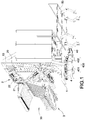
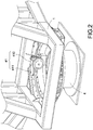
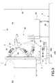
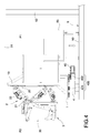
- Figs. 1 , 3 , and 4 are respectively a perspective view of a rotary dynamic simulation device, a schematic view showing a carrying seat of the rotary dynamic simulation device being in the first position, a schematic view showing the carrying seat of the rotary dynamic simulation device being in the second position according to the present invention.
- the present invention provides a rotary dynamic simulation device, and the rotary dynamic simulation device is disposed on the rack 5 of an audiovisual apparatus (as shown in Fig. 6 or Fig. 7 ).
- the rack 5 includes a first positon P1 and a second position P2 opposite to the first position P1.
- the first position P1 is an entering position from which a viewer gets on the rotary dynamic simulation device
- the second position P2 is a watch position to which the viewer is sent for a realistic experience.
- the viewer enters the dynamic simulation device from the first position P1 to seat himself, and is sent to the second position P2 by means of the rotary dynamic simulation device.
- the rotary dynamic simulation device includes a fixed table 1, a motion mechanism 2, a carrying seat3, and a rotation mechanism 4.
- the fixed table 1 is adapted to position and secure the rotary dynamic simulation device on the rack 5 of the audiovisual apparatus, and an arm 10 is vertically disposed thereon for installing the motion mechanism 2.
- the motion mechanism 2 has 6 degrees of freedom and includes a fixed plate 20, a movable plate 21, and a plurality of telescopic rods 22 connected between the fixed plate 20 and the movable plate 21, thereby forming the motion mechanism 2 having multiple degrees of freedom like a Stewart platform. Since the motion mechanism 2 is a conventional technique and is not within the protection scope of the present invention, so detailed descriptions are omitted herein for brevity.
- the carrying seat 3 is adapted for seating the viewer.
- the carrying seat 3 includes a carrying space 30, the movable plate 21 of the motion mechanism 2 is fixed to any position at a back side of the carrying space 30, the fixed plate 20 of the motion mechanism 2 is fixed to the arm 10 of the fixed table 1, and thereby the carrying seat 3 can be suspended by the fixed securement provided by the motion mechanism 2, at the same time the motion mechanism 2 does not block the view in front of the carrying seat 3, and the lateral configuration reduces the overall vertical space, which is beneficial to make scenic designs and surrounding layouts.
- the rotation mechanism 4 drives the fixed table 1 to rotate planarly, thereby driving the carrying seat 3 to rotate between the first position P1 and the second position P2 of the rack 5, as shown in Figs. 3 and 4 .
- the rack 5 includes a lower board 50, an upper board 51, and an upright pole 52 to support the upper board 51 above the lower board 50, and an elevator platform 53 can be disposed on the lower board 50 corresponding to the first position P1.
- the second position P2 is suspended outside the lower board 50, and the rotation mechanism 4 is disposed on the lower board 50.
- the rotation mechanism 4 is disposed below the fixed table 1.
- the rotation mechanism 4 includes a drive unit 40.
- the drive unit 40 can be a control motor for controlling the rotation mechanism 4 via the transmission wheel assembly 400 to rotate by a predetermined angle or in a predetermined range.
- the transmission wheel assembly 400 includes a first transmission wheel 401 disposed on the rotation mechanism 4 and a second transmission wheel 402 engaged with the first transmission wheel 401 and driven by the drive unit 40.
- the first transmission wheel 401 can be a large gear or a large friction wheel.
- the second transmission wheel 402 can be a relatively smaller gear or friction wheel and can be provided with a brake device 41.
- the brake device 41 includes anactuating element 410 and a brake element 411 which are disposed between the rotation mechanism 4 and the fixed table 1, so as to brake when the fixed table 1 is rotated by the rotation mechanism 4 to a fixed position (the first position P1 or the second position P2), thereby ensuring safety for the viewer by preventing the rotation mechanism 4 from wobbling or continuing to rotate/move, and the rotation mechanism 4 can brake immediately to stop its rotation when an emergency occurs.
- the rotation mechanism 4 can be disposed under the upper board 51 of the rack 5.
- the rotation mechanism 4 is disposed above the fixed table 1, so that the entire rotary dynamic simulation device is suspended in the rack 5.
- the present invention provides an audiovisual apparatus having the rotary dynamic simulation device.
- the audiovisual apparatus includes the rack 5 and a screen 6. At least one rotary dynamic simulation device is disposed on the rack 5; the rotary dynamic simulation device is mentioned above, so detailed descriptions thereof are not repeated.
- the rack 5 can be divided into multiple layers. A plurality of rotary dynamic simulation devices can be arranged side by side in each layer, so as to dispose more rotary dynamic simulation devices on the rack 5 for allowing more viewers to use at the same time. Therefore, the rack 5 includes a said first position P1 and a said second position P2 opposite to the said first position P1 corresponding to each of the rotary dynamic simulation devices, as shown in Fig. 7 . Furthermore, there can be multiple racks disposed back to back.
- the screen 6 can display pictures and/or play audio, or create a realistic effect in virtual reality, and the screen 6 is disposed corresponding to the second position P2 of the rack 5. Furthermore, as shown in Fig. 7 , if there are multiple racks 5, there can be multiple screens 6, and the screens 6 correspond in number to the multiple racks 5.
- the rotary dynamic simulation device includes a fixed table 1, a motion mechanism 4, a carrying seat 3, and a rotation mechanism 4.
- the motion mechanism 2 having multiple degrees of freedom is disposed between the fixed table 1 and the carrying seat 3.
- the rotation mechanism 4 is disposed on the rack 5 to drive the fixed table 1 to rotate, so that the carrying seat 3 is rotatable between an entering position and a watch position of the rack 5.
- the rotary dynamic simulation device of the present invention is constituted as above.
- the present invention can achieve functions as expected, solve problems existing in the conventional techniques, and have novelty and non-obviousness, so the present invention meets the requirements of patentability.
- a request to patent the present invention is kindly solicited according to the patent law.
Claims (11)
- Rotationende dynamische Simulationsvorrichtung, die auf einem Gestell (5) angeordnet ist, wobei die rotierende dynamische Simulationsvorrichtung umfasst:einen feststehenden Tisch (1), wobei ein Arm (10) vertikal auf dem feststehenden Tisch (1) angeordnet ist;einen Bewegungsmechanismus (2) mit mehreren Freiheitsgraden, der eine feste Platte (20), eine bewegliche Platte (21) und eine Vielzahl von Teleskopstangen (22) umfasst, die zwischen der festen Platte (20) und der beweglichen Platte (21) befestigt sind, wobei die feste Platte (20) an dem Arm (10) befestigt ist;einen Tragesitz (3) mit einem Trageraum (30), wobei die bewegliche Platte (21) an einer beliebigen Position an einer Rückseite des Trageraums (30) befestigt ist;
dadurch gekennzeichnet, dass der Tragesitz (3) konfiguriert ist, um sich zwischen einer ersten Position (P1) und einer zweiten Position (P2) gegenüber der ersten Position (P1) zu drehen; und dass die rotierende dynamische Simulationsvorrichtung weiterhin umfasst:einen Drehmechanismus (4), wobei der Drehmechanismus (4) auf dem Gestell (5) angeordnet ist und den feststehenden Tisch (1) antreibt, um dadurch den Tragesitz (3) von der ersten Position (P1) in die zweite Position (P2) zu drehen. - Rotationende dynamische Simulationsvorrichtung, nach Anspruch 1, wobei der Drehmechanismus (4) mit einer Bremseinrichtung (41) ausgestattet ist.
- Rotationende dynamische Simulationsvorrichtung, nach Anspruch 2, wobei die Bremseinrichtung (41) ein Betätigungselement (410) und ein Bremselement (411) aufweist, die zwischen dem Drehmechanismus (4) und dem feststehenden Tisch (1) angeordnet sind.
- Rotationende dynamische Simulationsvorrichtung, nach Anspruch 3, wobei der Drehmechanismus (4) eine Antriebseinheit (40) zur Steuerung der Rotation des Drehmechanismus (4) aufweist.
- Rotationende dynamische Simulationsvorrichtung, nach Anspruch 4, wobei die Antriebseinheit (40) den Drehmechanismus (4) über eine Getrieberad-Anordnung (400) steuert.
- Rotationende dynamische Simulationsvorrichtung, nach Anspruch 5, wobei die Getrieberad-Anordnung (400) ein erstes Getrieberad (401) aufweist, das an dem Drehmechanismus (4) angeordnet ist, und ein zweites Getrieberad (402) aufweist, das mit dem ersten Getrieberad (401) in Eingriff steht und von der Antriebseinheit (40) angetrieben wird.
- Audiovisuelle Vorrichtung mit einer rotierenden dynamischen Simulationsvorrichtung, gekennzeichnet durch:ein Gestell (5);mindestens eine rotierende dynamische Simulationsvorrichtung wie in einem der Ansprüche 1 bis 6 beansprucht;einen Bildschirm (6), der entsprechend der zweiten Position (P2) angeordnet ist.
- Audiovisuelle Vorrichtung mit der rotierenden dynamischen Simulationsvorrichtung nach Anspruch 7, wobei die erste Position (P1) eine Eintrittsposition, die zweite Position (P2) eine Uhrenposition ist.
- Audiovisuelle Vorrichtung mit der rotierenden dynamischen Simulationsvorrichtung nach Anspruch 8, wobei das Gestell (5) eine untere Platte (50) und eine Aufzugsplattform (53) aufweist, die entsprechend der Eintrittsposition angeordnet ist.
- Audiovisuelle Vorrichtung mit der rotierenden dynamischen Simulationseinrichtung nach Anspruch 9, wobei der Drehmechanismus (4) auf der unteren Platte (50) und unter dem feststehenden Tisch (1) angeordnet ist.
- Audiovisuelle Vorrichtung mit einer rotierenden dynamischen Simulationsvorrichtung nach Anspruch 9, wobei das Gestell (5) ferner eine obere Platte (51) aufweist und der Drehmechanismus (4) unterhalb der oberen Platte (51) und oberhalb des feststehenden Tisches (1) angeordnet ist.
Priority Applications (4)
| Application Number | Priority Date | Filing Date | Title |
|---|---|---|---|
| EP16158058.4A EP3213801B1 (de) | 2016-03-01 | 2016-03-01 | Rotierende dynamische simulationsvorrichtung und audiovisuelle vorrichtung damit |
| PL16158058T PL3213801T3 (pl) | 2016-03-01 | 2016-03-01 | Obrotowe dynamiczne urządzenie symulacyjne i przyrząd audiowizualny wykorzystujący to urządzenie |
| DK16158058.4T DK3213801T3 (en) | 2016-03-01 | 2016-03-01 | Rotating dynamic simulation device and audiovisual apparatus using the same |
| ES16158058.4T ES2682116T3 (es) | 2016-03-01 | 2016-03-01 | Dispositivo de simulación dinámica rotatorio y aparato audiovisual que lo usa |
Applications Claiming Priority (1)
| Application Number | Priority Date | Filing Date | Title |
|---|---|---|---|
| EP16158058.4A EP3213801B1 (de) | 2016-03-01 | 2016-03-01 | Rotierende dynamische simulationsvorrichtung und audiovisuelle vorrichtung damit |
Publications (2)
| Publication Number | Publication Date |
|---|---|
| EP3213801A1 EP3213801A1 (de) | 2017-09-06 |
| EP3213801B1 true EP3213801B1 (de) | 2018-06-20 |
Family
ID=55456630
Family Applications (1)
| Application Number | Title | Priority Date | Filing Date |
|---|---|---|---|
| EP16158058.4A Active EP3213801B1 (de) | 2016-03-01 | 2016-03-01 | Rotierende dynamische simulationsvorrichtung und audiovisuelle vorrichtung damit |
Country Status (4)
| Country | Link |
|---|---|
| EP (1) | EP3213801B1 (de) |
| DK (1) | DK3213801T3 (de) |
| ES (1) | ES2682116T3 (de) |
| PL (1) | PL3213801T3 (de) |
Family Cites Families (7)
| Publication number | Priority date | Publication date | Assignee | Title |
|---|---|---|---|---|
| US3469837A (en) * | 1966-03-09 | 1969-09-30 | Morton L Heilig | Experience theater |
| US5192247A (en) * | 1991-03-27 | 1993-03-09 | Universal City Studios, Inc. | Ride attraction |
| CN1297329C (zh) * | 2003-04-15 | 2007-01-31 | 李明 | 娱乐用动作模拟设备 |
| US8444496B2 (en) * | 2011-04-08 | 2013-05-21 | Brogent Technologies Inc. | Lateral dynamic simulation device |
| KR101276711B1 (ko) * | 2011-04-20 | 2013-06-19 | 주식회사 포디존 | 글라이더 모션 시뮬레이터 |
| KR101198255B1 (ko) * | 2012-04-12 | 2012-11-07 | 주식회사 모션디바이스 | 모션 시뮬레이터 |
| KR101250429B1 (ko) * | 2012-08-28 | 2013-04-08 | 주식회사 모션디바이스 | 모션 시뮬레이터 |
-
2016
- 2016-03-01 DK DK16158058.4T patent/DK3213801T3/en active
- 2016-03-01 PL PL16158058T patent/PL3213801T3/pl unknown
- 2016-03-01 ES ES16158058.4T patent/ES2682116T3/es active Active
- 2016-03-01 EP EP16158058.4A patent/EP3213801B1/de active Active
Non-Patent Citations (1)
| Title |
|---|
| None * |
Also Published As
| Publication number | Publication date |
|---|---|
| ES2682116T3 (es) | 2018-09-18 |
| EP3213801A1 (de) | 2017-09-06 |
| PL3213801T3 (pl) | 2018-10-31 |
| DK3213801T3 (en) | 2018-08-06 |
Similar Documents
| Publication | Publication Date | Title |
|---|---|---|
| KR102060596B1 (ko) | 비행 극장 | |
| US9823693B2 (en) | Robotically controlled convertible display | |
| US9511299B1 (en) | Rotary dynamic simulation device and audiovisual apparatus using the same | |
| EP2846322A1 (de) | Bewegungssimulator | |
| US20140117182A1 (en) | Simultaneously foldable multi-screen monitor arm device | |
| CN103212205B (zh) | 一种机动多自由度乘坐式大型娱乐体验装置 | |
| KR101049198B1 (ko) | 뒤틀림 방지 및 수직 지지력이 보강된 시뮬레이터 | |
| KR101596943B1 (ko) | 복수 인원 탑승용 회전식 시뮬레이터 및 그를 사용한 원형 구조 시뮬레이션 시스템 | |
| JP6285973B2 (ja) | 2自由度回転のモーションシミュレーター | |
| JP2013147925A (ja) | 可変視野角を有する可動式スタンド | |
| US8721464B2 (en) | Biaxial suspension type dynamic simulator | |
| DK2795401T3 (en) | Film display device and method for displaying a film | |
| JP2021502160A5 (de) | ||
| WO2014114409A1 (en) | Driving simulator | |
| CN105005321A (zh) | 跳楼机及其动感乘骑运动系统 | |
| EP3213801B1 (de) | Rotierende dynamische simulationsvorrichtung und audiovisuelle vorrichtung damit | |
| JP2014509401A (ja) | 3dの動的表示装置 | |
| CA2947361C (en) | Rotary dynamic simulation device and audiovisual apparatus using the same | |
| KR101326181B1 (ko) | 3축 모션베이스 장치 | |
| CN211124497U (zh) | 一种模拟机教员控制台系统 | |
| EP3563915A1 (de) | Bewegungssimulationsvorrichtung | |
| KR102101004B1 (ko) | 서지/롤 모션과 vr 혼합 영상이 결합된 대형 시뮬레이터 | |
| JP6964663B2 (ja) | 運動シミュレーションシステム | |
| KR101741119B1 (ko) | 시뮬레이팅 시스템 | |
| US20220254268A1 (en) | Motion system |
Legal Events
| Date | Code | Title | Description |
|---|---|---|---|
| PUAI | Public reference made under article 153(3) epc to a published international application that has entered the european phase |
Free format text: ORIGINAL CODE: 0009012 |
|
| STAA | Information on the status of an ep patent application or granted ep patent |
Free format text: STATUS: REQUEST FOR EXAMINATION WAS MADE |
|
| 17P | Request for examination filed |
Effective date: 20170117 |
|
| AK | Designated contracting states |
Kind code of ref document: A1 Designated state(s): AL AT BE BG CH CY CZ DE DK EE ES FI FR GB GR HR HU IE IS IT LI LT LU LV MC MK MT NL NO PL PT RO RS SE SI SK SM TR |
|
| AX | Request for extension of the european patent |
Extension state: BA ME |
|
| RIC1 | Information provided on ipc code assigned before grant |
Ipc: A63G 31/16 20060101AFI20171023BHEP Ipc: G09B 9/14 20060101ALI20171023BHEP |
|
| GRAP | Despatch of communication of intention to grant a patent |
Free format text: ORIGINAL CODE: EPIDOSNIGR1 |
|
| STAA | Information on the status of an ep patent application or granted ep patent |
Free format text: STATUS: GRANT OF PATENT IS INTENDED |
|
| INTG | Intention to grant announced |
Effective date: 20171213 |
|
| RIN1 | Information on inventor provided before grant (corrected) |
Inventor name: CHIEN, KE-CHENG Inventor name: LAI, DENG-HORNG Inventor name: HUANG, CHENG-LIN |
|
| GRAS | Grant fee paid |
Free format text: ORIGINAL CODE: EPIDOSNIGR3 |
|
| GRAA | (expected) grant |
Free format text: ORIGINAL CODE: 0009210 |
|
| STAA | Information on the status of an ep patent application or granted ep patent |
Free format text: STATUS: THE PATENT HAS BEEN GRANTED |
|
| AK | Designated contracting states |
Kind code of ref document: B1 Designated state(s): AL AT BE BG CH CY CZ DE DK EE ES FI FR GB GR HR HU IE IS IT LI LT LU LV MC MK MT NL NO PL PT RO RS SE SI SK SM TR |
|
| REG | Reference to a national code |
Ref country code: GB Ref legal event code: FG4D |
|
| REG | Reference to a national code |
Ref country code: IE Ref legal event code: FG4D |
|
| REG | Reference to a national code |
Ref country code: AT Ref legal event code: REF Ref document number: 1010155 Country of ref document: AT Kind code of ref document: T Effective date: 20180715 |
|
| REG | Reference to a national code |
Ref country code: DE Ref legal event code: R096 Ref document number: 602016003600 Country of ref document: DE |
|
| REG | Reference to a national code |
Ref country code: CH Ref legal event code: NV Representative=s name: WEINMANN ZIMMERLI AG, CH |
|
| REG | Reference to a national code |
Ref country code: DK Ref legal event code: T3 Effective date: 20180730 |
|
| REG | Reference to a national code |
Ref country code: SE Ref legal event code: TRGR |
|
| REG | Reference to a national code |
Ref country code: ES Ref legal event code: FG2A Ref document number: 2682116 Country of ref document: ES Kind code of ref document: T3 Effective date: 20180918 |
|
| REG | Reference to a national code |
Ref country code: NL Ref legal event code: FP |
|
| REG | Reference to a national code |
Ref country code: NO Ref legal event code: T2 Effective date: 20180620 |
|
| PG25 | Lapsed in a contracting state [announced via postgrant information from national office to epo] |
Ref country code: LT Free format text: LAPSE BECAUSE OF FAILURE TO SUBMIT A TRANSLATION OF THE DESCRIPTION OR TO PAY THE FEE WITHIN THE PRESCRIBED TIME-LIMIT Effective date: 20180620 Ref country code: BG Free format text: LAPSE BECAUSE OF FAILURE TO SUBMIT A TRANSLATION OF THE DESCRIPTION OR TO PAY THE FEE WITHIN THE PRESCRIBED TIME-LIMIT Effective date: 20180920 |
|
| REG | Reference to a national code |
Ref country code: LT Ref legal event code: MG4D |
|
| PG25 | Lapsed in a contracting state [announced via postgrant information from national office to epo] |
Ref country code: GR Free format text: LAPSE BECAUSE OF FAILURE TO SUBMIT A TRANSLATION OF THE DESCRIPTION OR TO PAY THE FEE WITHIN THE PRESCRIBED TIME-LIMIT Effective date: 20180921 Ref country code: HR Free format text: LAPSE BECAUSE OF FAILURE TO SUBMIT A TRANSLATION OF THE DESCRIPTION OR TO PAY THE FEE WITHIN THE PRESCRIBED TIME-LIMIT Effective date: 20180620 Ref country code: LV Free format text: LAPSE BECAUSE OF FAILURE TO SUBMIT A TRANSLATION OF THE DESCRIPTION OR TO PAY THE FEE WITHIN THE PRESCRIBED TIME-LIMIT Effective date: 20180620 Ref country code: RS Free format text: LAPSE BECAUSE OF FAILURE TO SUBMIT A TRANSLATION OF THE DESCRIPTION OR TO PAY THE FEE WITHIN THE PRESCRIBED TIME-LIMIT Effective date: 20180620 |
|
| PG25 | Lapsed in a contracting state [announced via postgrant information from national office to epo] |
Ref country code: EE Free format text: LAPSE BECAUSE OF FAILURE TO SUBMIT A TRANSLATION OF THE DESCRIPTION OR TO PAY THE FEE WITHIN THE PRESCRIBED TIME-LIMIT Effective date: 20180620 Ref country code: RO Free format text: LAPSE BECAUSE OF FAILURE TO SUBMIT A TRANSLATION OF THE DESCRIPTION OR TO PAY THE FEE WITHIN THE PRESCRIBED TIME-LIMIT Effective date: 20180620 Ref country code: SK Free format text: LAPSE BECAUSE OF FAILURE TO SUBMIT A TRANSLATION OF THE DESCRIPTION OR TO PAY THE FEE WITHIN THE PRESCRIBED TIME-LIMIT Effective date: 20180620 Ref country code: CZ Free format text: LAPSE BECAUSE OF FAILURE TO SUBMIT A TRANSLATION OF THE DESCRIPTION OR TO PAY THE FEE WITHIN THE PRESCRIBED TIME-LIMIT Effective date: 20180620 |
|
| PG25 | Lapsed in a contracting state [announced via postgrant information from national office to epo] |
Ref country code: SM Free format text: LAPSE BECAUSE OF FAILURE TO SUBMIT A TRANSLATION OF THE DESCRIPTION OR TO PAY THE FEE WITHIN THE PRESCRIBED TIME-LIMIT Effective date: 20180620 |
|
| REG | Reference to a national code |
Ref country code: DE Ref legal event code: R097 Ref document number: 602016003600 Country of ref document: DE |
|
| PLBE | No opposition filed within time limit |
Free format text: ORIGINAL CODE: 0009261 |
|
| STAA | Information on the status of an ep patent application or granted ep patent |
Free format text: STATUS: NO OPPOSITION FILED WITHIN TIME LIMIT |
|
| 26N | No opposition filed |
Effective date: 20190321 |
|
| PG25 | Lapsed in a contracting state [announced via postgrant information from national office to epo] |
Ref country code: SI Free format text: LAPSE BECAUSE OF FAILURE TO SUBMIT A TRANSLATION OF THE DESCRIPTION OR TO PAY THE FEE WITHIN THE PRESCRIBED TIME-LIMIT Effective date: 20180620 |
|
| REG | Reference to a national code |
Ref country code: AT Ref legal event code: UEP Ref document number: 1010155 Country of ref document: AT Kind code of ref document: T Effective date: 20180620 |
|
| PG25 | Lapsed in a contracting state [announced via postgrant information from national office to epo] |
Ref country code: MC Free format text: LAPSE BECAUSE OF FAILURE TO SUBMIT A TRANSLATION OF THE DESCRIPTION OR TO PAY THE FEE WITHIN THE PRESCRIBED TIME-LIMIT Effective date: 20180620 |
|
| PG25 | Lapsed in a contracting state [announced via postgrant information from national office to epo] |
Ref country code: LU Free format text: LAPSE BECAUSE OF NON-PAYMENT OF DUE FEES Effective date: 20190301 Ref country code: AL Free format text: LAPSE BECAUSE OF FAILURE TO SUBMIT A TRANSLATION OF THE DESCRIPTION OR TO PAY THE FEE WITHIN THE PRESCRIBED TIME-LIMIT Effective date: 20180620 |
|
| PG25 | Lapsed in a contracting state [announced via postgrant information from national office to epo] |
Ref country code: IE Free format text: LAPSE BECAUSE OF NON-PAYMENT OF DUE FEES Effective date: 20190301 |
|
| PG25 | Lapsed in a contracting state [announced via postgrant information from national office to epo] |
Ref country code: PT Free format text: LAPSE BECAUSE OF FAILURE TO SUBMIT A TRANSLATION OF THE DESCRIPTION OR TO PAY THE FEE WITHIN THE PRESCRIBED TIME-LIMIT Effective date: 20181022 Ref country code: MT Free format text: LAPSE BECAUSE OF NON-PAYMENT OF DUE FEES Effective date: 20190301 |
|
| PG25 | Lapsed in a contracting state [announced via postgrant information from national office to epo] |
Ref country code: CY Free format text: LAPSE BECAUSE OF FAILURE TO SUBMIT A TRANSLATION OF THE DESCRIPTION OR TO PAY THE FEE WITHIN THE PRESCRIBED TIME-LIMIT Effective date: 20180620 |
|
| PG25 | Lapsed in a contracting state [announced via postgrant information from national office to epo] |
Ref country code: HU Free format text: LAPSE BECAUSE OF FAILURE TO SUBMIT A TRANSLATION OF THE DESCRIPTION OR TO PAY THE FEE WITHIN THE PRESCRIBED TIME-LIMIT; INVALID AB INITIO Effective date: 20160301 |
|
| PG25 | Lapsed in a contracting state [announced via postgrant information from national office to epo] |
Ref country code: MK Free format text: LAPSE BECAUSE OF FAILURE TO SUBMIT A TRANSLATION OF THE DESCRIPTION OR TO PAY THE FEE WITHIN THE PRESCRIBED TIME-LIMIT Effective date: 20180620 |
|
| PGFP | Annual fee paid to national office [announced via postgrant information from national office to epo] |
Ref country code: SE Payment date: 20221129 Year of fee payment: 8 Ref country code: NO Payment date: 20221130 Year of fee payment: 8 Ref country code: FR Payment date: 20221129 Year of fee payment: 8 |
|
| PGFP | Annual fee paid to national office [announced via postgrant information from national office to epo] |
Ref country code: PL Payment date: 20221130 Year of fee payment: 8 |
|
| PGFP | Annual fee paid to national office [announced via postgrant information from national office to epo] |
Ref country code: FI Payment date: 20230315 Year of fee payment: 8 Ref country code: DK Payment date: 20230314 Year of fee payment: 8 Ref country code: AT Payment date: 20230227 Year of fee payment: 8 |
|
| PGFP | Annual fee paid to national office [announced via postgrant information from national office to epo] |
Ref country code: TR Payment date: 20230227 Year of fee payment: 8 Ref country code: IT Payment date: 20230330 Year of fee payment: 8 Ref country code: BE Payment date: 20230216 Year of fee payment: 8 |
|
| P01 | Opt-out of the competence of the unified patent court (upc) registered |
Effective date: 20230421 |
|
| PGFP | Annual fee paid to national office [announced via postgrant information from national office to epo] |
Ref country code: ES Payment date: 20230404 Year of fee payment: 8 Ref country code: CH Payment date: 20230401 Year of fee payment: 8 |
|
| PGFP | Annual fee paid to national office [announced via postgrant information from national office to epo] |
Ref country code: IS Payment date: 20240313 Year of fee payment: 9 |
|
| PGFP | Annual fee paid to national office [announced via postgrant information from national office to epo] |
Ref country code: NL Payment date: 20240214 Year of fee payment: 9 |
|
| PGFP | Annual fee paid to national office [announced via postgrant information from national office to epo] |
Ref country code: AT Payment date: 20240226 Year of fee payment: 9 |
|
| PGFP | Annual fee paid to national office [announced via postgrant information from national office to epo] |
Ref country code: FI Payment date: 20240315 Year of fee payment: 9 Ref country code: DE Payment date: 20240326 Year of fee payment: 9 Ref country code: GB Payment date: 20240201 Year of fee payment: 9 |