EP3211456A1 - Data processing device, method for determining characteristics of pixels, data processing method, and program - Google Patents
Data processing device, method for determining characteristics of pixels, data processing method, and program Download PDFInfo
- Publication number
- EP3211456A1 EP3211456A1 EP15853380.2A EP15853380A EP3211456A1 EP 3211456 A1 EP3211456 A1 EP 3211456A1 EP 15853380 A EP15853380 A EP 15853380A EP 3211456 A1 EP3211456 A1 EP 3211456A1
- Authority
- EP
- European Patent Office
- Prior art keywords
- pixel
- data processing
- correction table
- measurement
- detector
- Prior art date
- Legal status (The legal status is an assumption and is not a legal conclusion. Google has not performed a legal analysis and makes no representation as to the accuracy of the status listed.)
- Granted
Links
Images






Classifications
-
- G—PHYSICS
- G01—MEASURING; TESTING
- G01T—MEASUREMENT OF NUCLEAR OR X-RADIATION
- G01T1/00—Measuring X-radiation, gamma radiation, corpuscular radiation, or cosmic radiation
- G01T1/16—Measuring radiation intensity
-
- G—PHYSICS
- G01—MEASURING; TESTING
- G01T—MEASUREMENT OF NUCLEAR OR X-RADIATION
- G01T1/00—Measuring X-radiation, gamma radiation, corpuscular radiation, or cosmic radiation
- G01T1/16—Measuring radiation intensity
- G01T1/17—Circuit arrangements not adapted to a particular type of detector
Definitions
- the present invention relates to a data processing apparatus to correct X-ray intensity data measured by a pixel detector, a method of obtaining characteristic of each pixel and a method of data processing, and a program.
- each pixel (including a strip) has an individual characteristic, and difference in gain, behavior, or sensitivity is generated among pixels and individual variation appears even when each pixel is uniformly irradiated with a X-ray (refer to Patent Literature 1, for example).
- an apparatus maker irradiates a detector with a uniform X-ray having a certain intensity before shipping a measurement apparatus, and thereby prepares a correction table to correct difference in a pixel gain or a count value among pixels (Flat-Field correction) according to a specific measurement condition, prepares a correction table to eliminate a bad pixel, or prepares a versatile table which can be used in some measurement conditions (refer to Patent Literatures 2 and 3, for example).
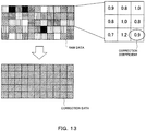
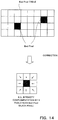
- FIG. 13 and FIG. 14 schematically show examples of the correction tables for the Flat-Field correction and correction for eliminating a bad pixel, respectively. Conventionally, a set of such correction tables is used for the correction.
- the set of correction tables as described above can be used only under a condition assumed in the adjustment. Then, even a normal pixel at a glance sometimes generates noise when exposed for a long time, or the correction value thereof is shifted sometimes when an X-ray having a count value significantly different from that in the Flat-Field correction is made to enter. In this manner, when measurement is desired to be performed in a condition different from that in the initial assumption, the apparatus maker side needs to take back the apparatus to prepare a correction table again.
- use temperature is set for the measurement apparatus and the allowable temperature range is assumed to be ⁇ 10°C of the use temperature, and data is guaranteed if the apparatus is used in this range.
- the measurement apparatus is brought into the apparatus maker and the correction table is adjusted.
- the kind of an X-ray source, the energy (wavelength) of an X-ray tube, an energy threshold value in measurement, or the like changes from the assumption at shipment, a new table becomes necessary.
- the present invention has been achieved in view of such a situation and has an object to provide a data processing apparatus that saves a trouble of setting a correction table again and enables a user to measure X-ray intensity data quickly under a desired condition, a method of obtaining the characteristic of each pixel and a method of data processing, and a program.
- FIG. 1 is a block diagram showing a configuration of a data processing apparatus 100.
- the data processing apparatus 100 is configured with a PC and connected to a measurement apparatus.
- the data processing apparatus 100 includes a measurement condition storage unit 110, a correction table generation unit 120, a characteristic storage unit 130, an approximate formula storage unit 140, a measurement data storage unit 150, a correction unit 160, and an output unit 170, and corrects X-ray intensity data measured by a detector.
- the detector is a one-dimensional or two-dimensional detector having a spatial minimum unit of a pixel (including a strip), and counts photons while removing noise of an electronic circuit using a threshold value.
- the measurement condition storage unit 110 stores an input measurement condition in measurement.
- the input may be performed automatically from the measurement apparatus, or may be performed manually by a user.
- the input measurement condition in the measurement includes temperature around the measurement apparatus. Thereby, it is possible to correct the X-ray intensity data with reference to the influence of the temperature such as noise shift caused according to the temperature in the measurement.
- the measurement condition in the measurement may be the kind of the X-ray source. As a result, also when the X-ray source is changed, it is possible to correct the X-ray intensity data quickly depending on the X-ray source.
- the measurement condition in the measurement may include atmospheric pressure or humidity.
- the correction table generation unit 120 applies the measurement condition input as that in the measurement by the detector and a value expressing a characteristic of each pixel to an approximate formula expressing a count value of each pixel, and generates a correction table for the detector using the calculation result of the approximate formula. Thereby, it is possible to change the measurement condition without taking back the measurement apparatus to an apparatus maker to set a correction table again. As a result, a user can measure the X-ray intensity data quickly under a desired condition.
- the detector to detect the X-ray intensity has the same pixel characteristic as a detector used for the generation of the correction table (specific detector), and the detected X-ray intensity is corrected by the use of the correction table.
- the correction table generation unit 120 uses a formula obtained by adding a formula expressing a primary count amount by the X-ray irradiation and a formula expressing a count amount by charge sharing, as the approximate formula expressing a count value of each pixel. Furthermore, the approximate formula expressing the primary count amount by the X-ray irradiation is a formula obtained by adding a formula expressing a count amount by noise and a formula expressing a count amount by other than the noise. Thereby, it is possible to eliminate the count amount by the noise and also to measure the X-ray intensity reflecting the influence of the charge sharing. Further, it is possible to set a complementary pixel efficiently with reference to the influence of the noise.
- the correction table generation unit 120 calculates a correction coefficient of each pixel for Flat-Field correction or distortion correction using the calculation result of the approximate formula. Thereby, it is possible to perform the Flat-Field correction or the distortion correction according to the measurement condition.
- the correction table generation unit 120 specifies a complementary pixel using the calculation result of the approximate formula and a threshold value of the count value, and calculates a correction coefficient for complementing the complementary pixel. Thereby, it is possible to set a complementary pixel efficiently according to the measurement condition. As a result, it becomes unnecessary to take back the measurement apparatus and to set the complementary pixel again every time the measurement condition is changed, and it becomes also unnecessary to set a complementary pixel uniformly for a plurality of conditions.
- the complementary pixel indicates a pixel which is a bad pixel whose detection value is not used and a target of pixel value complementation by any method.
- the characteristic storage unit 130 stores the characteristic of each pixel in the detector. A method of obtaining the characteristic of each pixel will be described below.
- the approximate formula storage unit 140 stores the approximate formula to be used in the correction table generation.
- the count amount by the noise can be expressed by a Gaussian function
- the count amount by other than the noise in the primary count amount by the X-ray irradiation can be expressed by an error function
- the count amount by the charge sharing can be expressed by a linear function. Details will be described below.
- the measurement data storage unit 150 stores measured data. For example, the measured data transmitted from the measurement apparatus is received by the data processing apparatus 100 and stored into the measurement data storage unit 150.
- the correction unit 160 corrects the X-ray intensity data measured by the detector using the generated correction table.
- the correction tables are put together into a single table, and the correction can be performed easily using only this correction table. Note that a plurality of tables may be retained and may be used compositely.
- the output unit 170 outputs the corrected X-ray intensity data.
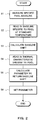
- FIG. 2 is a flowchart showing a method of setting the characteristic of each pixel in advance.
- the detector is irradiated uniformly with the X-ray while the measurement condition is changed, the detection value of each pixel is recorded, and a baseline is measured for each pixel by the use of the recorded detection value (step S1).
- the baseline is an average value obtained including other pixels, for example.
- the baseline specific to a pixel at a standard temperature is read in from the database (step S2), and the shift of the baseline is calculated (step S3).
- the thermal characteristic specific to a pixel is read in from the database (step S4), and a parameter (characteristic) to return the baseline shift is calculated (step S5) .
- the characteristic of each pixel is calculated from the recorded detection value of each pixel to be used, and the obtained parameter is stored in the characteristic storage unit to be set (step S6). Thereby, it becomes possible to correct the X-ray intensity according to a desired measurement condition using the characteristic of each pixel stored in the data processing apparatus.
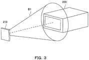
- FIG. 3 is a perspective view of a scene of the uniform irradiation to the detector 220.
- the uniform irradiation of the X-ray can be performed by means of irradiating the detector 220 with an X-ray beam B1 which is diffused uniformly by a diffusion plate 210 as shown in FIG. 3 , for example. In this manner, an integral profile of the X-ray is obtained for each pixel.
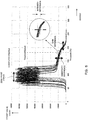
- FIG. 4 is a graph showing the integral profile of the X-ray in one pixel.
- the graph of FIG. 4 shows energy in the horizontal axis and a count value in the vertical axis, and shows a count value integrated from the high energy side. Accordingly, the position where the count value increases abruptly indicates a peak position of X-ray energy, and the height of a curve at a threshold value indicates an integral count value. Further, noise appears on the lower energy side having a right-and-left symmetric shape (Rice distribution) in which the upper end is cut out by saturation, and the center position thereof indicates the zero point.
- Ice distribution right-and-left symmetric shape
- FIG. 5 is a graph showing a corrected X-ray integral profile in a plurality of pixels.
- the correction reduces sensitivity difference, gain difference, zero point error difference, and the like among the plurality of pixels.
- the intensity difference in the integral count value among pixels at the threshold value becomes small.
- FIG. 6 is a flowchart showing an action of the data processing apparatus 100.
- the measurement condition is input into the data processing apparatus 100 (step T1). Then, the characteristic prepared preliminarily for each pixel and the approximate formula obtained under the measurement condition are fitted to the X-ray intensity data (step T2). Thereby, the correction coefficient of each pixel is obtained for the Flat-Field correction.
- step T3 it is determined whether or not each pixel is to be set as the complementary pixel. For example, the determination is performed depending on whether or not the noise distribution overlaps the energy range not smaller than the threshold value. In this case, when the noise overlaps the threshold value, the information of this pixel cannot be used and therefore it is determined that the complementary pixel setting is to be performed.
- step T4 when the complementary pixel setting is determined to be performed, the X-ray intensity of this pixel is not taken and the correction table is set so as to complement this pixel with surrounding pixels (step T4).
- step T5 the X-ray intensity is corrected by the use of the obtained correction table (step T5).
- FIG. 7 is a schematic diagram showing a correction method using the data processing apparatus.
- the approximate formula expressing the count value of each pixel in the detector is calculated by the use of the characteristic of each pixel and the measurement condition in the measurement by the detector such as a gain, a RICE position, temperature, ⁇ (time constant of count omission), or the like.
- the correction table C1 is generated for the detector by the fitting of the approximate formula to the X-ray intensity.
- FIG. 8 is a graph showing an obtained integral profile.
- the integral profile is shifted by temperature, variation of non-sensitivity layer thickness of the detector, the kind of the X-ray source, or the like.
- the zero point is shifted by the temperature
- the counting rate is changed by the temperature or the variation of the non-sensitivity layer thickness
- the gain is changed by the temperature.
- the integral profile can be affected by atmospheric pressure, humidity, or the like. For example, since the change of the atmospheric pressure changes the absorption rate of the X-ray from the X-ray source to the detector, the count intensity decreases when the atmospheric pressure is higher and the count intensity increases when the atmospheric pressure is lower.
- FIG. 9 is a graph showing each term of the approximate formula.
- the count amount by the noise can be approximated by a Gaussian function as shown in Formula (1).
- the count amount by other than the noise can be approximated by an error function (complementary error function) as shown in Formula (2).
- the count amount by the charge sharing can be approximated by a linear function shown in Formula (3). Note that the above formulas are representative examples and the formulas expressing the respective count amounts are not always limited to these formulas.
- the primary count amount by the X-ray irradiation can be expressed as shown in Formula (4) by the use of Formulas (2) and (3).
- the detection amount generated by the charge sharing is evaluated as a linear function of a difference between a peak energy on the high energy side and a target energy.
- the target energy means an energy for which a detection amount generated by the charge sharing is to be calculated.
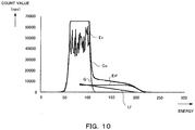
- FIG. 10 is a graph showing a result of the fitting of the approximate formula to the integral profile. As shown in FIG. 10 , it is possible to fit an approximate formula profile Co obtained by adding a Gaussian function G, an error function Erf, and a linear function Lf, to a profile Ex of an experimental result. The correction coefficient is obtained from a coefficient obtained at this time, and the correction table can be generated.
- FIG. 11 is a graph showing an example of the noise integral profile. As shown in FIG. 11 , even a threshold value set at a position not affected by the noise (edge of a skirt) in the case of 10 second exposure falls in the affected range in the case of the noise of 20 second exposure. In this manner, the pixel becomes a target of the complementary pixel setting depending on the threshold value position.
- FIG. 12 is a graph showing the number of bad pixels with respect to a measurement time. As the exposure time is increased as described above, even the threshold value of the same position overlaps the noise profile. As shown in FIG. 12 , while the number of bad pixels is increased as the measurement time increases, it is possible to provide a correction table to complement the increased bad pixels.
Landscapes
- Physics & Mathematics (AREA)
- Health & Medical Sciences (AREA)
- Life Sciences & Earth Sciences (AREA)
- General Physics & Mathematics (AREA)
- High Energy & Nuclear Physics (AREA)
- Molecular Biology (AREA)
- Spectroscopy & Molecular Physics (AREA)
- Measurement Of Radiation (AREA)
- Apparatus For Radiation Diagnosis (AREA)
Abstract
Description
- The present invention relates to a data processing apparatus to correct X-ray intensity data measured by a pixel detector, a method of obtaining characteristic of each pixel and a method of data processing, and a program.
- In recent years, a semiconductor detector of a photon counting type has been used for X-ray intensity measurement. In such a detector, each pixel (including a strip) has an individual characteristic, and difference in gain, behavior, or sensitivity is generated among pixels and individual variation appears even when each pixel is uniformly irradiated with a X-ray (refer to
Patent Literature 1, for example). - Accordingly, an apparatus maker irradiates a detector with a uniform X-ray having a certain intensity before shipping a measurement apparatus, and thereby prepares a correction table to correct difference in a pixel gain or a count value among pixels (Flat-Field correction) according to a specific measurement condition, prepares a correction table to eliminate a bad pixel, or prepares a versatile table which can be used in some measurement conditions (refer to
Patent Literatures 2 and 3, for example).FIG. 13 andFIG. 14 schematically show examples of the correction tables for the Flat-Field correction and correction for eliminating a bad pixel, respectively. Conventionally, a set of such correction tables is used for the correction. -
- Patent Literature 1:
U.S. Unexamined Patent Application Publication No. 2005/0259790 - Patent Literature 2: Publication of
U.S. Patent No. 6792159 - Patent Literature 3: Publication of
U.S. patent No. 5272536 - However, the set of correction tables as described above can be used only under a condition assumed in the adjustment. Then, even a normal pixel at a glance sometimes generates noise when exposed for a long time, or the correction value thereof is shifted sometimes when an X-ray having a count value significantly different from that in the Flat-Field correction is made to enter. In this manner, when measurement is desired to be performed in a condition different from that in the initial assumption, the apparatus maker side needs to take back the apparatus to prepare a correction table again.
- For example, use temperature is set for the measurement apparatus and the allowable temperature range is assumed to be ±10°C of the use temperature, and data is guaranteed if the apparatus is used in this range. When desired to be used at a temperature deviated from the guarantee range by 15°C or more, the measurement apparatus is brought into the apparatus maker and the correction table is adjusted. When, in addition to such a change of the use environment temperature caused by the change of an installation site or the like, the kind of an X-ray source, the energy (wavelength) of an X-ray tube, an energy threshold value in measurement, or the like changes from the assumption at shipment, a new table becomes necessary.
- Further, variation exists even within the allowable temperature range of the specification, and sometimes a larger number of complementary pixels are set so as to neglect the variation or to allow usage within the whole range. When a table is prepared assuming a bad pixel caused in any of the conditions as a consistent bad pixel, the image does not have any problem, but it is inefficient that the X-ray intensities of pixels more than required are not used when the table is used. In this manner, it is necessary to prepare a table which can be used as much as possible in the range of the condition, by an inefficient greatest common divisor approach.
- The present invention has been achieved in view of such a situation and has an object to provide a data processing apparatus that saves a trouble of setting a correction table again and enables a user to measure X-ray intensity data quickly under a desired condition, a method of obtaining the characteristic of each pixel and a method of data processing, and a program.
-
- (1) For achieving the above object, a data processing apparatus of the present invention is a data processing apparatus that corrects X-ray intensity data measured by a pixel detector, including: a characteristic storage unit to store a characteristic of each pixel in a specific detector; a correction table generation unit to apply a measurement condition input as that in measurement by the specific detector, and a value expressing the characteristic of each pixel to an approximate formula expressing a count value of the each pixel and to generate a correction table for the specific detector using a calculation result of the approximate formula; and a correction unit to correct X-ray intensity data measured by the specific detector using the generated correction table.
In this manner, the data processing apparatus of the present invention generates the correction table according to the input measurement condition, and thereby it is possible to change a measurement condition without setting a correction table again by taking back a measurement apparatus to an apparatus maker. As a result, a user can measure the X-ray intensity data quickly under a desired condition. - (2) Further, in the data processing apparatus of the present invention, the correction table generation unit uses a formula obtained by adding a formula expressing a primary count amount by X-ray irradiation and a formula expressing a count amount by charge sharing, as the approximate formula expressing the count value of each pixel. Thereby, it is possible to generate the correction table referring to the influence of the charge sharing.
- (3) Further, in the data processing apparatus of the present invention, the correction table generation unit uses a formula obtained by adding a formula expressing a count amount by noise and a formula expressing a count amount by other than the noise, as the approximate formula expressing the primary count amount by the X-ray irradiation. Thereby, it is possible to measure the X-ray intensity avoiding the noise. In addition, it is possible to set a complementary pixel efficiently by referring to the influence of the noise according to the measurement condition.
- (4) Further, in the data processing apparatus of the present invention, the correction table generation unit calculates a correction coefficient for Flat-Field correction or distortion correction for each pixel using a calculation result of the approximate formula expressing the count value of each pixel. Thereby, it is possible to perform the Flat-Field correction or the distortion correction according to the measurement condition.
- (5) Further, in the data processing apparatus of the present invention, the correction table generation unit specifies a bad pixel using a calculation result of the approximate formula expressing the count value of each pixel and a threshold value of the count value, and calculates a correction coefficient for complementing the bad pixel. Thereby, it is possible to set a complementary pixel efficiently according to the measurement condition. As a result, it becomes unnecessary to set the complementary pixel again by taking back the measurement apparatus every time the measurement condition is changed, and it becomes also unnecessary to set the complementary pixel uniformly for a plurality of conditions.
- (6) Further, in the data processing apparatus of the present invention, the input measurement condition in the measurement includes temperature around a measurement apparatus. Thereby, it is possible to correct the X-ray intensity data using a correction table referring to the influence of the temperature such as noise shift caused according to the temperature in the measurement.
- (7) Further, in the data processing apparatus of the present invention, the input measurement condition in the measurement includes a kind of an X-ray source used for the measurement. Thereby, when the X-ray source is changed, it is possible to correct the X-ray intensity data using a correction table which is generated quickly according to an X-ray source to be used.
- (8) Further, in a method of the present invention, the input measurement condition in the measurement includes a kind of an X-ray source used for the measurement. Thereby, it is possible to store the characteristic of each pixel in the data processing apparatus and correct the X-ray intensity data using a correction table derived from the characteristic of each pixel according to a desired measurement condition.
- (9) Further, a method of the present invention is a method of data processing for correcting X-ray intensity data measured by a pixel detector, including the steps of: applying a measurement condition input as that in measurement by a specific detector and a preliminarily stored value expressing a characteristic of each pixel in a specific detector to an approximate formula expressing a count value of the each pixel and generating a correction table for the specific detector using a calculation result of the approximate formula expressing the count value of each pixel; and correcting X-ray intensity data measured by the specific detector using the generated correction table. Thereby, a user can measure the X-ray intensity data quickly under a desired condition.
- (10) Further, a program of the present invention is a program of data processing program for correcting X-ray intensity data measured by a pixel detector, causing a computer to execute the processes of: applying a measurement condition input as that in measurement by a specific detector and a preliminarily stored value expressing a characteristic of each pixel in a specific detector to an approximate formula expressing a count value of the each pixel and generating a correction table for the specific detector using a calculation result of the approximate formula expressing the count value of each pixel; and correcting X-ray intensity data measured by the specific detector using the generated correction table. Thereby, a user can measure the X-ray intensity data quickly under a desired condition.
- According to the present invention, it is possible to save a trouble of setting a correction table again, and to allow a user to measure X-ray intensity data quickly under a desired condition.
-
-
FIG. 1 is a block diagram showing a configuration of a data processing apparatus of the present invention. -
FIG. 2 is a flowchart showing a method of setting characteristic of each pixel in advance. -
FIG. 3 is a perspective view showing a scene of uniform irradiation to a detector. -
FIG. 4 is a graph showing an X-ray integral profile in one pixel. -
FIG. 5 is a graph showing a corrected X-ray integral profile in a plurality of pixels. -
FIG. 6 is a flowchart showing an action of the data processing apparatus of the present invention. -
FIG. 7 is a schematic diagram showing a correction method using a data processing apparatus of the present invention. -
FIG. 8 is a graph showing an obtained integral profile. -
FIG. 9 is a graph showing each term of an approximate formula. -
FIG. 10 is a graph showing a result of fitting an approximate formula to an integral profile. -
FIG. 11 is a graph showing an example of a noise integral profile. -
FIG. 12 is a graph showing the number of bad pixels with respect to a measurement time. -
FIG. 13 is a diagram schematically showing an example of a correction table for Flat-Field correction. -
FIG. 14 is a diagram schematically showing an example of a correction table for correction of eliminating a bad pixel. - Next, an embodiment of the present invention will be explained with reference to the drawings. For easy understanding of the explanation, the same reference numeral is attached to the same element in each of the drawings and duplicated explanation will be omitted.
-
FIG. 1 is a block diagram showing a configuration of adata processing apparatus 100. For example, thedata processing apparatus 100 is configured with a PC and connected to a measurement apparatus. As shown inFIG. 1 , thedata processing apparatus 100 includes a measurementcondition storage unit 110, a correctiontable generation unit 120, acharacteristic storage unit 130, an approximateformula storage unit 140, a measurementdata storage unit 150, acorrection unit 160, and anoutput unit 170, and corrects X-ray intensity data measured by a detector. The detector is a one-dimensional or two-dimensional detector having a spatial minimum unit of a pixel (including a strip), and counts photons while removing noise of an electronic circuit using a threshold value. - The measurement
condition storage unit 110 stores an input measurement condition in measurement. The input may be performed automatically from the measurement apparatus, or may be performed manually by a user. For example, the input measurement condition in the measurement includes temperature around the measurement apparatus. Thereby, it is possible to correct the X-ray intensity data with reference to the influence of the temperature such as noise shift caused according to the temperature in the measurement. Further, the measurement condition in the measurement may be the kind of the X-ray source. As a result, also when the X-ray source is changed, it is possible to correct the X-ray intensity data quickly depending on the X-ray source. In addition, the measurement condition in the measurement may include atmospheric pressure or humidity. - The correction
table generation unit 120 applies the measurement condition input as that in the measurement by the detector and a value expressing a characteristic of each pixel to an approximate formula expressing a count value of each pixel, and generates a correction table for the detector using the calculation result of the approximate formula. Thereby, it is possible to change the measurement condition without taking back the measurement apparatus to an apparatus maker to set a correction table again. As a result, a user can measure the X-ray intensity data quickly under a desired condition. - Here, in the present embodiment, the detector to detect the X-ray intensity has the same pixel characteristic as a detector used for the generation of the correction table (specific detector), and the detected X-ray intensity is corrected by the use of the correction table.
- The correction
table generation unit 120 uses a formula obtained by adding a formula expressing a primary count amount by the X-ray irradiation and a formula expressing a count amount by charge sharing, as the approximate formula expressing a count value of each pixel. Furthermore, the approximate formula expressing the primary count amount by the X-ray irradiation is a formula obtained by adding a formula expressing a count amount by noise and a formula expressing a count amount by other than the noise. Thereby, it is possible to eliminate the count amount by the noise and also to measure the X-ray intensity reflecting the influence of the charge sharing. Further, it is possible to set a complementary pixel efficiently with reference to the influence of the noise. - The correction
table generation unit 120 calculates a correction coefficient of each pixel for Flat-Field correction or distortion correction using the calculation result of the approximate formula. Thereby, it is possible to perform the Flat-Field correction or the distortion correction according to the measurement condition. - The correction
table generation unit 120 specifies a complementary pixel using the calculation result of the approximate formula and a threshold value of the count value, and calculates a correction coefficient for complementing the complementary pixel. Thereby, it is possible to set a complementary pixel efficiently according to the measurement condition. As a result, it becomes unnecessary to take back the measurement apparatus and to set the complementary pixel again every time the measurement condition is changed, and it becomes also unnecessary to set a complementary pixel uniformly for a plurality of conditions. Here, the complementary pixel indicates a pixel which is a bad pixel whose detection value is not used and a target of pixel value complementation by any method. - The
characteristic storage unit 130 stores the characteristic of each pixel in the detector. A method of obtaining the characteristic of each pixel will be described below. The approximateformula storage unit 140 stores the approximate formula to be used in the correction table generation. For the approximate formula, for example, the count amount by the noise can be expressed by a Gaussian function, the count amount by other than the noise in the primary count amount by the X-ray irradiation can be expressed by an error function, and the count amount by the charge sharing can be expressed by a linear function. Details will be described below. - The measurement
data storage unit 150 stores measured data. For example, the measured data transmitted from the measurement apparatus is received by thedata processing apparatus 100 and stored into the measurementdata storage unit 150. - The
correction unit 160 corrects the X-ray intensity data measured by the detector using the generated correction table. In the present embodiment, the correction tables are put together into a single table, and the correction can be performed easily using only this correction table. Note that a plurality of tables may be retained and may be used compositely. Theoutput unit 170 outputs the corrected X-ray intensity data. - Next, a method of preliminarily preparing a characteristic for each pixel in the detector will be explained.
FIG. 2 is a flowchart showing a method of setting the characteristic of each pixel in advance. First, the detector is irradiated uniformly with the X-ray while the measurement condition is changed, the detection value of each pixel is recorded, and a baseline is measured for each pixel by the use of the recorded detection value (step S1). The baseline is an average value obtained including other pixels, for example. - Next, the baseline specific to a pixel at a standard temperature is read in from the database (step S2), and the shift of the baseline is calculated (step S3). Meanwhile, the thermal characteristic specific to a pixel is read in from the database (step S4), and a parameter (characteristic) to return the baseline shift is calculated (step S5) . In this manner, the characteristic of each pixel is calculated from the recorded detection value of each pixel to be used, and the obtained parameter is stored in the characteristic storage unit to be set (step S6). Thereby, it becomes possible to correct the X-ray intensity according to a desired measurement condition using the characteristic of each pixel stored in the data processing apparatus.
- The above uniform irradiation will be explained.
FIG. 3 is a perspective view of a scene of the uniform irradiation to thedetector 220. The uniform irradiation of the X-ray can be performed by means of irradiating thedetector 220 with an X-ray beam B1 which is diffused uniformly by adiffusion plate 210 as shown inFIG. 3 , for example. In this manner, an integral profile of the X-ray is obtained for each pixel. -
FIG. 4 is a graph showing the integral profile of the X-ray in one pixel. The graph ofFIG. 4 shows energy in the horizontal axis and a count value in the vertical axis, and shows a count value integrated from the high energy side. Accordingly, the position where the count value increases abruptly indicates a peak position of X-ray energy, and the height of a curve at a threshold value indicates an integral count value. Further, noise appears on the lower energy side having a right-and-left symmetric shape (Rice distribution) in which the upper end is cut out by saturation, and the center position thereof indicates the zero point. -
FIG. 5 is a graph showing a corrected X-ray integral profile in a plurality of pixels. The correction reduces sensitivity difference, gain difference, zero point error difference, and the like among the plurality of pixels. In the example shown inFIG. 5 , as the result of the correction, the intensity difference in the integral count value among pixels at the threshold value becomes small. - It is possible to prepare the correction table according to the measurement condition using the characteristic of each pixel obtained as above.
FIG. 6 is a flowchart showing an action of thedata processing apparatus 100. - As shown in
FIG. 6 , first, the measurement condition is input into the data processing apparatus 100 (step T1). Then, the characteristic prepared preliminarily for each pixel and the approximate formula obtained under the measurement condition are fitted to the X-ray intensity data (step T2). Thereby, the correction coefficient of each pixel is obtained for the Flat-Field correction. - Next, it is determined whether or not each pixel is to be set as the complementary pixel (step T3). For example, the determination is performed depending on whether or not the noise distribution overlaps the energy range not smaller than the threshold value. In this case, when the noise overlaps the threshold value, the information of this pixel cannot be used and therefore it is determined that the complementary pixel setting is to be performed.
- In this manner, when the complementary pixel setting is determined to be performed, the X-ray intensity of this pixel is not taken and the correction table is set so as to complement this pixel with surrounding pixels (step T4). When the complementary pixel setting is determined not to be performed, the process proceeds to step T5. Then, the X-ray intensity is corrected by the use of the obtained correction table (step T5). Here, it becomes possible to perform the action as above by causing the apparatus to execute a program.
-
FIG. 7 is a schematic diagram showing a correction method using the data processing apparatus. As shown inFIG. 7 , the approximate formula expressing the count value of each pixel in the detector is calculated by the use of the characteristic of each pixel and the measurement condition in the measurement by the detector such as a gain, a RICE position, temperature, τ (time constant of count omission), or the like. Then, the correction table C1 is generated for the detector by the fitting of the approximate formula to the X-ray intensity. Then, it becomes possible to correct the X-ray intensity data M1 measured by the detector using the generated correction table C1 and to obtain corrected data M2. - In the following, there will be explained the fitting when the correction coefficient is calculated by the use of the approximate formula.
FIG. 8 is a graph showing an obtained integral profile. As shown inFIG. 8 , the integral profile is shifted by temperature, variation of non-sensitivity layer thickness of the detector, the kind of the X-ray source, or the like. For example, the zero point is shifted by the temperature, the counting rate is changed by the temperature or the variation of the non-sensitivity layer thickness, and the gain is changed by the temperature. Further, the integral profile can be affected by atmospheric pressure, humidity, or the like. For example, since the change of the atmospheric pressure changes the absorption rate of the X-ray from the X-ray source to the detector, the count intensity decreases when the atmospheric pressure is higher and the count intensity increases when the atmospheric pressure is lower. - The integral profile like this is expressed by the approximate formula.
FIG. 9 is a graph showing each term of the approximate formula. For example, the count amount by the noise can be approximated by a Gaussian function as shown in Formula (1). Further, in the primary count amount by the X-ray irradiation, the count amount by other than the noise can be approximated by an error function (complementary error function) as shown in Formula (2). Further, the count amount by the charge sharing can be approximated by a linear function shown in Formula (3). Note that the above formulas are representative examples and the formulas expressing the respective count amounts are not always limited to these formulas.
[Formula 1]


- For example, the primary count amount by the X-ray irradiation can be expressed as shown in Formula (4) by the use of Formulas (2) and (3). In this case, the detection amount generated by the charge sharing is evaluated as a linear function of a difference between a peak energy on the high energy side and a target energy. Here, the target energy means an energy for which a detection amount generated by the charge sharing is to be calculated.
[Formula 4]
- I(E): Intensity of the X-ray profile at a certain energy threshold value E
- A and B: Real constant determined by the X-ray intensity and the like
- Epeak: Primary peak energy not affected by the charge share
- It is also possible to express the primary count amount by the X-ray irradiation as shown in Formula (5) by overlapping diffraction data supposed to be detected by the charge sharing of diffraction data on the high energy side for each pixel in the X-ray detector and thereby evaluating the charge sharing. By the calculation of the detection amount generated by the charge sharing in this manner, not only accurate evaluation is obtained but also an effect of reproducing an X-ray profile shape by the charge share is obtained without depending on a pixel shape or the like.

- I(E): Intensity of the X-ray profile at a certain energy threshold value E
- A, B, and C: Real constant determined by the X-ray intensity and the like
- Epeak: Primary peak energy not affected by the charge share
- Ecs: Apparent energy generated by the charge share
- pcs(Ecs): Probability of collecting charge corresponding to Ecs in a target pixel
- ΔS: Area of a region where apparent energy by the charge share changes by ΔE
-
FIG. 10 is a graph showing a result of the fitting of the approximate formula to the integral profile. As shown inFIG. 10 , it is possible to fit an approximate formula profile Co obtained by adding a Gaussian function G, an error function Erf, and a linear function Lf, to a profile Ex of an experimental result. The correction coefficient is obtained from a coefficient obtained at this time, and the correction table can be generated. - In the following, noise handling will be explained.
FIG. 11 is a graph showing an example of the noise integral profile. As shown inFIG. 11 , even a threshold value set at a position not affected by the noise (edge of a skirt) in the case of 10 second exposure falls in the affected range in the case of the noise of 20 second exposure. In this manner, the pixel becomes a target of the complementary pixel setting depending on the threshold value position. -
FIG. 12 is a graph showing the number of bad pixels with respect to a measurement time. As the exposure time is increased as described above, even the threshold value of the same position overlaps the noise profile. As shown inFIG. 12 , while the number of bad pixels is increased as the measurement time increases, it is possible to provide a correction table to complement the increased bad pixels. -
- 100
- Data processing apparatus
- 110
- Measurement condition storage unit
- 120
- Correction table generation unit
- 130
- Characteristic storage unit
- 140
- Approximate formula storage unit
- 150
- Measurement data storage unit
- 160
- Correction unit
- 170
- Output unit
- 210
- Diffusion plate
- 220
- Detector
- B1
- X-ray beam
- C1
- Correction table
- Co
- Approximate formula profile
- Erf
- Error function
- Ex
- Experimental result profile
- G
- Gaussian function
- Lf
- Linear function
- M1
- X-ray intensity data
- M2
- Corrected data
Claims (10)
- A data processing apparatus that corrects X-ray intensity data measured by a pixel detector, comprising:a characteristic storage unit to store a characteristic of each pixel in a specific detector;a correction table generation unit to apply a measurement condition input as that in measurement by the specific detector, and a value expressing the characteristic of each pixel to an approximate formula expressing a count value of the each pixel and to generate a correction table for the specific detector using a calculation result of the approximate formula; anda correction unit to correct X-ray intensity data measured by the specific detector using the generated correction table.
- The data processing apparatus according to claim 1, wherein
the correction table generation unit uses a formula obtained by adding a formula expressing a primary count amount by X-ray irradiation and a formula expressing a count amount by charge sharing, as the approximate formula expressing the count value of each pixel. - The data processing apparatus according to claim 2, wherein
the correction table generation unit uses a formula obtained by adding a formula expressing a count amount by noise and a formula expressing a count amount by other than the noise, as the approximate formula expressing the primary count amount by the X-ray irradiation. - The data processing apparatus according to any of claims 1 to 3, wherein
the correction table generation unit calculates a correction coefficient for Flat-Field correction or distortion correction for each pixel using a calculation result of the approximate formula expressing the count value of each pixel. - The data processing apparatus according to any of claims 1 to 4, wherein
the correction table generation unit specifies a bad pixel using a calculation result of the approximate formula expressing the count value of each pixel and a threshold value of the count value, and calculates a correction coefficient for complementing the bad pixel. - The data processing apparatus according to any of claims 1 to 5, wherein
the input measurement condition in the measurement includes temperature around a measurement apparatus. - The data processing apparatus according to any of claims 1 to 6, wherein
the input measurement condition in the measurement includes a kind of an X-ray source used for the measurement. - A method of obtaining the characteristic of each pixel stored in the data processing apparatus according to any of claims 1 to 7, comprising the steps of:uniformly irradiating the specific detector with an X-ray while changing a specific measurement condition, and recording a detection value of each pixel; andcalculating a characteristic of each pixel from the recorded detection value of each pixel.
- A method of data processing for correcting X-ray intensity data measured by a pixel detector, comprising the steps of:applying a measurement condition input as that in measurement by a specific detector and a preliminarily stored value expressing a characteristic of each pixel in a specific detector to an approximate formula expressing a count value of the each pixel and generating a correction table for the specific detector using a calculation result of the approximate formula expressing the count value of each pixel; andcorrecting X-ray intensity data measured by the specific detector using the generated correction table.
- A program of data processing program for correcting X-ray intensity data measured by a pixel detector, causing a computer to execute the processes of:applying a measurement condition input as that in measurement by a specific detector and a preliminarily stored value expressing a characteristic of each pixel in a specific detector to an approximate formula expressing a count value of the each pixel and generating a correction table for the specific detector using a calculation result of the approximate formula expressing the count value of each pixel; andcorrecting X-ray intensity data measured by the specific detector using the generated correction table.
Applications Claiming Priority (2)
| Application Number | Priority Date | Filing Date | Title |
|---|---|---|---|
| JP2014217751 | 2014-10-24 | ||
| PCT/JP2015/069924 WO2016063586A1 (en) | 2014-10-24 | 2015-07-10 | Data processing device, method for determining characteristics of pixels, data processing method, and program |
Publications (3)
| Publication Number | Publication Date |
|---|---|
| EP3211456A1 true EP3211456A1 (en) | 2017-08-30 |
| EP3211456A4 EP3211456A4 (en) | 2018-07-11 |
| EP3211456B1 EP3211456B1 (en) | 2026-04-29 |
Family
ID=55760636
Family Applications (1)
| Application Number | Title | Priority Date | Filing Date |
|---|---|---|---|
| EP15853380.2A Active EP3211456B1 (en) | 2014-10-24 | 2015-07-10 | Data processing apparatus, method of data processing, and computer program |
Country Status (5)
| Country | Link |
|---|---|
| US (1) | US10551510B2 (en) |
| EP (1) | EP3211456B1 (en) |
| JP (1) | JP6524473B2 (en) |
| CN (1) | CN106796298B (en) |
| WO (1) | WO2016063586A1 (en) |
Families Citing this family (7)
| Publication number | Priority date | Publication date | Assignee | Title |
|---|---|---|---|---|
| JP6524473B2 (en) * | 2014-10-24 | 2019-06-05 | 株式会社リガク | Data processing apparatus, method of determining characteristics of each pixel, and method and program of data processing |
| JP6775777B2 (en) * | 2017-08-29 | 2020-10-28 | 株式会社リガク | How to display the measurement result in X-ray diffraction measurement |
| JP6873414B2 (en) * | 2017-10-17 | 2021-05-19 | 株式会社リガク | Processing equipment, methods and programs |
| EP3508887A1 (en) * | 2018-01-09 | 2019-07-10 | Koninklijke Philips N.V. | Charge sharing calibration method and system |
| CN108490480B (en) * | 2018-03-22 | 2019-10-29 | 北京大学 | Data processing method on particles detection and its star |
| CN115023629B (en) | 2020-01-27 | 2025-11-18 | 株式会社理学 | Control devices, systems, methods, and non-transitory computer-readable recording media |
| CN114324421B (en) * | 2021-12-06 | 2023-06-27 | 武汉联影生命科学仪器有限公司 | Data correction method, device, computer equipment and storage medium |
Family Cites Families (23)
| Publication number | Priority date | Publication date | Assignee | Title |
|---|---|---|---|---|
| JPS5366778A (en) | 1976-11-26 | 1978-06-14 | Mitsubishi Electric Corp | Meter using radioactive rays |
| US4992706A (en) * | 1990-02-21 | 1991-02-12 | North American Philips Corporation | CRT raster distortion correction circuit |
| DE69116905T2 (en) | 1990-03-13 | 1996-06-13 | Sony Corp., Tokio/Tokyo | Shading effects corrector |
| US5640436A (en) * | 1995-01-26 | 1997-06-17 | Hitachi Medical Corporation | Method and apparatus for X-ray computed tomography |
| US6134292A (en) * | 1998-07-13 | 2000-10-17 | General Electric Company | Methods and apparatus for reducing z-axis non-uniformity artifacts |
| US6476394B1 (en) * | 1999-11-26 | 2002-11-05 | Konica Corporation | Radiation image capturing apparatus |
| US6792159B1 (en) | 1999-12-29 | 2004-09-14 | Ge Medical Systems Global Technology Company, Llc | Correction of defective pixels in a detector using temporal gradients |
| JP2002000593A (en) | 2000-06-23 | 2002-01-08 | Canon Inc | Imaging device, imaging system, imaging method, and storage medium |
| US6694172B1 (en) * | 2001-06-23 | 2004-02-17 | Koninklijke Philips Electronics, N.V. | Fault-tolerant detector for gamma ray imaging |
| DE102004025121A1 (en) | 2004-05-21 | 2005-12-15 | Bruker Axs Gmbh | Method for operating an X-ray analysis device with two-dimensional array detector and X-ray analysis device for carrying out the method |
| WO2007125691A1 (en) | 2006-04-28 | 2007-11-08 | Hitachi Medical Corporation | X-ray image diagnostic device |
| JP4945249B2 (en) * | 2007-01-10 | 2012-06-06 | 株式会社東芝 | X-ray transmission image display system |
| JP2010074641A (en) | 2008-09-19 | 2010-04-02 | Konica Minolta Medical & Graphic Inc | Radiograph detector, and system and program for defective pixel determination |
| JP2011180095A (en) | 2010-03-03 | 2011-09-15 | Fujifilm Corp | Radiation image photographing device, radiation image photographing system, and program |
| JP5455857B2 (en) * | 2010-09-28 | 2014-03-26 | 富士フイルム株式会社 | Radiation image capturing apparatus, radiation image capturing method, and radiation image capturing program |
| CN101975965B (en) * | 2010-10-27 | 2012-07-25 | 江苏康众数字医疗设备有限公司 | Flat panel detector and temperature calibration method and image correction method thereof |
| CN102346260B (en) * | 2011-06-08 | 2013-12-18 | 上海奕瑞光电子科技有限公司 | X-ray flat panel detector with temperature sensing function and preparation method thereof |
| DE102011077859B4 (en) * | 2011-06-21 | 2014-01-23 | Siemens Aktiengesellschaft | Quantum counting radiation detector |
| JP5914381B2 (en) * | 2013-02-19 | 2016-05-11 | 株式会社リガク | X-ray data processing apparatus, X-ray data processing method, and X-ray data processing program |
| JP5816316B2 (en) * | 2013-03-29 | 2015-11-18 | 富士フイルム株式会社 | RADIOGRAPHIC IMAGE DETECTION DEVICE, ITS OPERATION METHOD, AND RADIOGRAPHY DEVICE |
| KR20140137715A (en) * | 2013-05-23 | 2014-12-03 | 삼성디스플레이 주식회사 | Apparatus and method for detecting x-ray |
| US20150085970A1 (en) * | 2013-09-23 | 2015-03-26 | General Electric Company | Systems and methods for hybrid scanning |
| JP6524473B2 (en) * | 2014-10-24 | 2019-06-05 | 株式会社リガク | Data processing apparatus, method of determining characteristics of each pixel, and method and program of data processing |
-
2015
- 2015-07-10 JP JP2016555103A patent/JP6524473B2/en active Active
- 2015-07-10 EP EP15853380.2A patent/EP3211456B1/en active Active
- 2015-07-10 US US15/516,777 patent/US10551510B2/en active Active
- 2015-07-10 WO PCT/JP2015/069924 patent/WO2016063586A1/en not_active Ceased
- 2015-07-10 CN CN201580045810.1A patent/CN106796298B/en active Active
Also Published As
| Publication number | Publication date |
|---|---|
| CN106796298B (en) | 2020-01-21 |
| EP3211456B1 (en) | 2026-04-29 |
| US20180203132A1 (en) | 2018-07-19 |
| JPWO2016063586A1 (en) | 2017-08-03 |
| WO2016063586A1 (en) | 2016-04-28 |
| EP3211456A4 (en) | 2018-07-11 |
| US10551510B2 (en) | 2020-02-04 |
| JP6524473B2 (en) | 2019-06-05 |
| CN106796298A (en) | 2017-05-31 |
Similar Documents
| Publication | Publication Date | Title |
|---|---|---|
| EP3211456A1 (en) | Data processing device, method for determining characteristics of pixels, data processing method, and program | |
| KR101283220B1 (en) | Radiation detector and radiation detecting method | |
| CN109216142B (en) | Electron probe microanalyzer and storage medium | |
| EP3342342B1 (en) | Radiation image processing method and radiographic system | |
| US20150279027A1 (en) | Image processing apparatus and imaging system | |
| US20110096906A1 (en) | Method and System for Extracting Spectroscopic Information from Images and Waveforms | |
| JP5914381B2 (en) | X-ray data processing apparatus, X-ray data processing method, and X-ray data processing program | |
| US8710446B2 (en) | Imaging apparatus, control method thereof, and program | |
| US8395126B2 (en) | X-ray imaging apparatus, X-ray imaging method, and computer storage medium | |
| US10755389B2 (en) | Image processing apparatus, image processing method, and medium | |
| US20150323687A1 (en) | Linear fitting of multi-threshold counting data | |
| US9310496B2 (en) | Calibration apparatus and method | |
| US20210191372A1 (en) | Analysis of additive manufacturing processes | |
| US20160162755A1 (en) | Image processing apparatus and image processing method | |
| US10918352B2 (en) | Device and method for scatter correction in an x-ray image | |
| JP4523958B2 (en) | X-ray fluorescence analyzer and program used therefor | |
| US9743902B2 (en) | Image processing apparatus, image processing method, radiation imaging system, and storage medium | |
| KR102001217B1 (en) | Method of calibrating an x-ray detector | |
| WO2016129455A1 (en) | Radiation measurement device and radiation measurement method | |
| JP6555164B2 (en) | Particle size distribution measuring apparatus, data processing method, and data processing program | |
| US7881893B2 (en) | Method for correcting biparametric spectra | |
| He et al. | Error analysis of laser beam quality measured with CCD sensor and choice of the optimal threshold | |
| EP3259617B1 (en) | Method for quantifying the intrinsic dimensions of radiation sensors, particularly ionizing radiation sensors, and device for implementing same | |
| US10031261B2 (en) | Method for measuring X-ray energy of an accelerator in an inspection system | |
| EP3864624B1 (en) | Method for correcting a spectral image |
Legal Events
| Date | Code | Title | Description |
|---|---|---|---|
| STAA | Information on the status of an ep patent application or granted ep patent |
Free format text: STATUS: THE INTERNATIONAL PUBLICATION HAS BEEN MADE |
|
| PUAI | Public reference made under article 153(3) epc to a published international application that has entered the european phase |
Free format text: ORIGINAL CODE: 0009012 |
|
| STAA | Information on the status of an ep patent application or granted ep patent |
Free format text: STATUS: REQUEST FOR EXAMINATION WAS MADE |
|
| 17P | Request for examination filed |
Effective date: 20170202 |
|
| AK | Designated contracting states |
Kind code of ref document: A1 Designated state(s): AL AT BE BG CH CY CZ DE DK EE ES FI FR GB GR HR HU IE IS IT LI LT LU LV MC MK MT NL NO PL PT RO RS SE SI SK SM TR |
|
| AX | Request for extension of the european patent |
Extension state: BA ME |
|
| DAV | Request for validation of the european patent (deleted) | ||
| DAX | Request for extension of the european patent (deleted) | ||
| A4 | Supplementary search report drawn up and despatched |
Effective date: 20180607 |
|
| RIC1 | Information provided on ipc code assigned before grant |
Ipc: G01T 1/17 20060101AFI20180601BHEP Ipc: G01T 1/16 20060101ALI20180601BHEP |
|
| STAA | Information on the status of an ep patent application or granted ep patent |
Free format text: STATUS: EXAMINATION IS IN PROGRESS |
|
| 17Q | First examination report despatched |
Effective date: 20210212 |
|
| GRAP | Despatch of communication of intention to grant a patent |
Free format text: ORIGINAL CODE: EPIDOSNIGR1 |
|
| STAA | Information on the status of an ep patent application or granted ep patent |
Free format text: STATUS: GRANT OF PATENT IS INTENDED |
|
| INTG | Intention to grant announced |
Effective date: 20250908 |
|
| GRAJ | Information related to disapproval of communication of intention to grant by the applicant or resumption of examination proceedings by the epo deleted |
Free format text: ORIGINAL CODE: EPIDOSDIGR1 |
|
| STAA | Information on the status of an ep patent application or granted ep patent |
Free format text: STATUS: EXAMINATION IS IN PROGRESS |
|
| INTC | Intention to grant announced (deleted) | ||
| GRAP | Despatch of communication of intention to grant a patent |
Free format text: ORIGINAL CODE: EPIDOSNIGR1 |
|
| STAA | Information on the status of an ep patent application or granted ep patent |
Free format text: STATUS: GRANT OF PATENT IS INTENDED |
|
| INTG | Intention to grant announced |
Effective date: 20260122 |
|
| GRAS | Grant fee paid |
Free format text: ORIGINAL CODE: EPIDOSNIGR3 |
|
| GRAA | (expected) grant |
Free format text: ORIGINAL CODE: 0009210 |
|
| STAA | Information on the status of an ep patent application or granted ep patent |
Free format text: STATUS: THE PATENT HAS BEEN GRANTED |
|
| AK | Designated contracting states |
Kind code of ref document: B1 Designated state(s): AL AT BE BG CH CY CZ DE DK EE ES FI FR GB GR HR HU IE IS IT LI LT LU LV MC MK MT NL NO PL PT RO RS SE SI SK SM TR |
|
| REG | Reference to a national code |
Ref country code: CH Ref legal event code: F10 Free format text: ST27 STATUS EVENT CODE: U-0-0-F10-F00 (AS PROVIDED BY THE NATIONAL OFFICE) Effective date: 20260429 Ref country code: CH Ref legal event code: R17 Free format text: ST27 STATUS EVENT CODE: U-0-0-R10-R17 (AS PROVIDED BY THE NATIONAL OFFICE) Effective date: 20260429 |