EP3342342B1 - Radiation image processing method and radiographic system - Google Patents
Radiation image processing method and radiographic system Download PDFInfo
- Publication number
- EP3342342B1 EP3342342B1 EP15902347.2A EP15902347A EP3342342B1 EP 3342342 B1 EP3342342 B1 EP 3342342B1 EP 15902347 A EP15902347 A EP 15902347A EP 3342342 B1 EP3342342 B1 EP 3342342B1
- Authority
- EP
- European Patent Office
- Prior art keywords
- radiation image
- image
- radiation
- psf
- scintillator
- Prior art date
- Legal status (The legal status is an assumption and is not a legal conclusion. Google has not performed a legal analysis and makes no representation as to the accuracy of the status listed.)
- Active
Links
- 230000005855 radiation Effects 0.000 title claims description 354
- 238000003672 processing method Methods 0.000 title claims description 20
- 238000012937 correction Methods 0.000 claims description 88
- 238000012545 processing Methods 0.000 claims description 14
- 230000001678 irradiating effect Effects 0.000 claims description 7
- 238000007781 pre-processing Methods 0.000 claims description 7
- 238000013500 data storage Methods 0.000 claims description 6
- 238000001228 spectrum Methods 0.000 claims description 6
- 230000007423 decrease Effects 0.000 claims description 5
- 238000012546 transfer Methods 0.000 claims description 5
- 238000000034 method Methods 0.000 description 19
- 230000007547 defect Effects 0.000 description 16
- 238000010586 diagram Methods 0.000 description 10
- 230000000694 effects Effects 0.000 description 8
- 238000005259 measurement Methods 0.000 description 7
- 238000000149 argon plasma sintering Methods 0.000 description 6
- 238000003745 diagnosis Methods 0.000 description 6
- 239000011159 matrix material Substances 0.000 description 5
- 206010006272 Breast mass Diseases 0.000 description 4
- 208000004434 Calcinosis Diseases 0.000 description 4
- 238000006243 chemical reaction Methods 0.000 description 4
- 238000009607 mammography Methods 0.000 description 4
- 230000002093 peripheral effect Effects 0.000 description 4
- 230000003321 amplification Effects 0.000 description 3
- 230000002708 enhancing effect Effects 0.000 description 3
- 238000011156 evaluation Methods 0.000 description 3
- 238000002474 experimental method Methods 0.000 description 3
- 238000003199 nucleic acid amplification method Methods 0.000 description 3
- 239000010409 thin film Substances 0.000 description 3
- 238000003705 background correction Methods 0.000 description 2
- 230000002950 deficient Effects 0.000 description 2
- 239000006185 dispersion Substances 0.000 description 2
- 238000002601 radiography Methods 0.000 description 2
- 238000012935 Averaging Methods 0.000 description 1
- XAGFODPZIPBFFR-UHFFFAOYSA-N aluminium Chemical compound [Al] XAGFODPZIPBFFR-UHFFFAOYSA-N 0.000 description 1
- 229910052782 aluminium Inorganic materials 0.000 description 1
- 238000004458 analytical method Methods 0.000 description 1
- 238000002059 diagnostic imaging Methods 0.000 description 1
- 231100000673 dose–response relationship Toxicity 0.000 description 1
- 238000003384 imaging method Methods 0.000 description 1
- 229920013655 poly(bisphenol-A sulfone) Polymers 0.000 description 1
- 238000011084 recovery Methods 0.000 description 1
- 230000003252 repetitive effect Effects 0.000 description 1
- 230000000007 visual effect Effects 0.000 description 1
Images


Classifications
-
- G—PHYSICS
- G06—COMPUTING; CALCULATING OR COUNTING
- G06T—IMAGE DATA PROCESSING OR GENERATION, IN GENERAL
- G06T7/00—Image analysis
- G06T7/0002—Inspection of images, e.g. flaw detection
- G06T7/0012—Biomedical image inspection
-
- A—HUMAN NECESSITIES
- A61—MEDICAL OR VETERINARY SCIENCE; HYGIENE
- A61B—DIAGNOSIS; SURGERY; IDENTIFICATION
- A61B6/00—Apparatus for radiation diagnosis, e.g. combined with radiation therapy equipment
- A61B6/42—Apparatus for radiation diagnosis, e.g. combined with radiation therapy equipment with arrangements for detecting radiation specially adapted for radiation diagnosis
- A61B6/4208—Apparatus for radiation diagnosis, e.g. combined with radiation therapy equipment with arrangements for detecting radiation specially adapted for radiation diagnosis characterised by using a particular type of detector
- A61B6/4233—Apparatus for radiation diagnosis, e.g. combined with radiation therapy equipment with arrangements for detecting radiation specially adapted for radiation diagnosis characterised by using a particular type of detector using matrix detectors
-
- A—HUMAN NECESSITIES
- A61—MEDICAL OR VETERINARY SCIENCE; HYGIENE
- A61B—DIAGNOSIS; SURGERY; IDENTIFICATION
- A61B6/00—Apparatus for radiation diagnosis, e.g. combined with radiation therapy equipment
- A61B6/52—Devices using data or image processing specially adapted for radiation diagnosis
- A61B6/5258—Devices using data or image processing specially adapted for radiation diagnosis involving detection or reduction of artifacts or noise
- A61B6/5282—Devices using data or image processing specially adapted for radiation diagnosis involving detection or reduction of artifacts or noise due to scatter
-
- G—PHYSICS
- G06—COMPUTING; CALCULATING OR COUNTING
- G06T—IMAGE DATA PROCESSING OR GENERATION, IN GENERAL
- G06T5/00—Image enhancement or restoration
-
- A—HUMAN NECESSITIES
- A61—MEDICAL OR VETERINARY SCIENCE; HYGIENE
- A61B—DIAGNOSIS; SURGERY; IDENTIFICATION
- A61B6/00—Apparatus for radiation diagnosis, e.g. combined with radiation therapy equipment
- A61B6/50—Clinical applications
- A61B6/502—Clinical applications involving diagnosis of breast, i.e. mammography
-
- A—HUMAN NECESSITIES
- A61—MEDICAL OR VETERINARY SCIENCE; HYGIENE
- A61B—DIAGNOSIS; SURGERY; IDENTIFICATION
- A61B6/00—Apparatus for radiation diagnosis, e.g. combined with radiation therapy equipment
- A61B6/58—Testing, adjusting or calibrating apparatus or devices for radiation diagnosis
- A61B6/586—Detection of faults or malfunction of the device
-
- G—PHYSICS
- G06—COMPUTING; CALCULATING OR COUNTING
- G06T—IMAGE DATA PROCESSING OR GENERATION, IN GENERAL
- G06T2207/00—Indexing scheme for image analysis or image enhancement
- G06T2207/10—Image acquisition modality
- G06T2207/10116—X-ray image
Definitions
- the present invention relates to a radiation image processing method and a radiographic system, and in particular, to a radiation image processing method and a radiographic system capable of correcting a blurring due to light scattering occurring in a scintillator panel of an indirect radiation detector.
- Medical imaging using a radiation is performed on a subject matter through a Compton effect that only a portion of energy of a radiation photon is delivered to electrons or a photoelectric effect that all energy is delivered to electrons and a radiation is completely absorbed. At this point, typically a radiation having energy of 10 keV to 200 keV is used.
- Digital radiography devices for obtaining a radiation image are divided into an indirect type equipment and a direct type equipment.
- a radiation collides with a scintillator of a scintillator panel to generate a visible light ray, and the visible light ray is transformed to an image signal through a thin film transistor in which a charge coupled device (CCD) or a photodiode is installed.
- CCD charge coupled device
- the direct type equipment obtains an image in a manner that a radiation passing through a subject is directly irradiated on a thin film transistor in which a photoconductor or a photoresistor is installed, and is transformed to an image signal.
- a radiation radiated from a radiation generating device is irradiated on a wide area at once in a cone type and causes image distortion due to radiation scattering.
- a method for removing such a scatter radiation a method using an anti-scatter grid or an air gap is used.
- the grid method uses a difference between a primary radiation almost perpendicularly incident to a radiation detector and a scatter radiation incident in a random direction. This method is to dispose the anti-scatter grid between a subject and a radiation detector, and to physically cut off the scatter radiation, which is obliquely incident in a process where a radiation passing through the subject passes through the grid, from reaching the radiation detector.
- the anti-scatter grid is composed of lead and aluminum.
- the method using the air gap is imaging with a space between a subject and a radiation detector.
- the scatter radiation is not perpendicularly but obliquely incident to the detector, and when there is the air gap between the detector and the subject, only the primary radiation among photons passing through the subject reaches the radiation detector. On the other hand, the scatter radiation is scattered to the surroundings and does not reach the radiation detector.
- Patent Literature Korean Patent Laid-open Publication No. 10-2012-0012736
- the present invention provides a radiation image processing method and a radiographic system capable of correcting a blurring, which occurs due to scattering occurred in a scintillator panel of an indirect radiation detector, with deconvolution using a point spread function (PSF).
- PSF point spread function
- a radiation image processing method includes: obtaining a radiation image using an indirect radiation detector including a scintillator panel and a pixel array panel; determining a parameter value for defining a point spread function (PSF) according to the scintillator panel or the pixel array panel; and correcting the radiation image by deconvoluting the radiation image using the PSF to which the parameter value is applied.
- PSF point spread function
- the radiation image processing method may further include removing a fault element from the radiation image before the correcting the radiation image by deconvoluting the radiation image.
- the parameter may define a magnitude of the PSF and a shape of the PSF.
- the parameter value may be determined to allow a correction image for which the radiation image is deconvoluted using the PSF to satisfy an image quality reference.
- the image quality may be evaluated by measuring at least any one selected from among a modulation transfer function (MTF), a detective quantum efficiency (DQE), a normalized noise power spectrum (NNPS), and a signal to noise ratio (SNR).
- MTF modulation transfer function
- DQE detective quantum efficiency
- NPS normalized noise power spectrum
- SNR signal to noise ratio
- the image quality reference may include a condition that a DQE value of the correction image is in a range of 90% to 110% of a DQE value of the radiation image in a same spatial frequency.
- the image quality reference may include a condition that for a spatial frequency of the correction image, a value of the MTF decreases according to an increase in spatial frequency, and the MTF value is a highest in the correction image according to the parameter value.
- the radiation image processing method may further include: classifying and storing the determined parameter value according to at least any one among a pixel size of the pixel array panel, a thickness of the scintillator panel, and a type of the scintillator, wherein in the correcting the radiation image by deconvoluting the radiation image, the radiation image is corrected by selecting a parameter value from among stored parameter values according to at least any one among the pixel size of the pixel array panel, the thickness of the scintillator panel, and the type of the scintillator, which are used for obtaining the radiation image.
- the radiation image may be corrected by iterating the deconvolution using the PSF to which the parameter value is applied.
- a radiographic system includes: a radiation irradiating unit irradiating a radiation on a subject; an indirect radiation detector including a scintillator panel converting a radiation, which passes through the subject and is incident thereto, to a visible light, and a pixel array panel storing charges generated by the visible light in each pixel, and realizing a radiation image according to a charge amount in each pixel; and an image processing unit correcting the radiation image by deconvoluting the radiation image obtained by the indirect radiation detector using a point spread function(PSF).
- PSF point spread function
- the image processing unit may include: a data storage unit in which a parameter value, which is applied to the PSF according to at least any one among a pixel size of the pixel array panel, a thickness of the scintillator panel, and a type of the scintillator, is classified and stored according to at least any one among the pixel size of the pixel array panel, the thickness of the scintillator panel, and the type of the scintillator; a parameter selecting unit selecting the parameter value according to the at least any one among a pixel size of the pixel array panel, a thickness of the scintillator panel, and a type of the scintillator; and an image correcting unit deconvoluting the radiation image using the PSF to which the selected parameter value is applied.
- the image processing unit may further include a preprocessing unit removing a fault element from the obtained radiation image.
- the image processing unit may further include an iteration setting unit setting a number of times of deconvoluting the radiation image.
- the iteration setting unit may set an iteration number for satisfying a condition that a DQE value of a correction image, which is corrected by deconvoluting the radiation image with the PSF, is in a range of 90% to 110% of a DQE value of the radiation image in a same spatial frequency.
- a radiation image processing method may correct a blurring of a radiation image, which is caused by scatting of light generated in a scintillator panel of an indirect radiation detector, by deconvoluting the radiation image using a point spread function (PSF). Accordingly, a radiation image of which the sharpness is improved with an indirect radiation detector may be obtained. In addition, since a radiation image of which the sharpness is improved with the indirect radiation detector having a high detective quantum efficiency (DQE) is obtained, a sharp radiation image may be obtained even with a small radiation dose and accordingly, a radiation exposure dose of a subject may be lowered.
- DQE detective quantum efficiency
- amplification of a defective element may be prevented in a process for correcting the blurring of the radiation image through preprocessing for removing the defective element before correcting the blurring of the radiation image.
- the blurring since the blurring is not artificially deleted but is mitigated to disappear, data information on the radiation image may be prevented from being lost.
- a point spread function depicts a shape that a point is represented by blurring in an image, and the extent of blurring may vary according to a shape of the PSF. For example, the larger the blurring area at each point in an image is, the blurring of the image gets more severe. Accordingly, the extent of blurring may be adjusted by adjusting the shape of the PSF, and using this, an image including the blurring may be obtained through convolution of a sharp image with the PSF.
- a blurring effect may be applied to the sharp image.
- a blurring of a radiation image may also be corrected by deconvoluting the radiation image with a PSF.
- the blurring is not artificially deleted but is mitigated to disappear and accordingly data information on the radiation image may not be lost. Accordingly, when the radiation image is corrected, quality of the radiation image may not be lowered.
- FIG. 1 is a flowchart illustrating a radiation image processing method according to an embodiment of the present invention.
- a radiation image processing method may include an operation S100 for obtaining a radiation image by using an indirect radiation detector, which includes a scintillator panel 110 and a pixel array panel 120; an operation S200 for determining a value of a parameter defining a PSF according to the scintillator panel 110 or the pixel array panel 120; and an operation S300 for correcting the radiation image by deconvoluting it with a PSF to which the parameter value is applied.
- an indirect radiation detector which includes a scintillator panel 110 and a pixel array panel 120
- an operation S200 for determining a value of a parameter defining a PSF according to the scintillator panel 110 or the pixel array panel 120
- an operation S300 for correcting the radiation image by deconvoluting it with a PSF to which the parameter value is applied.
- the radiation image is obtained (operation S100) using the indirect radiation detector including the scintillator 110 and the pixel array panel 120.
- the radiation image is obtained with the indirect radiation detector using the scintillator panel 110, a blurring occurs by light scattered by a scintillator 111 of the scintillator panel 110.
- the light scattering by the scintillator 111 may have a Gaussian shape.
- the radiation image including the blurring in the present invention is defined as an image for which a sharp image is convoluted with a PSF.
- the radiation image is corrected by deconvoluting the radiation image including the blurring using the PSF.
- the pixel array panel 120 may store, for each pixel, charges generated by the visible light into which a radiation irradiated on the scintillator panel 110 is converted.
- the resolution of the radiation image may vary according to a pixel size of the pixel array panel 120.
- the parameter value, which defines the PSF according to the scintillator panel 110 or the pixel array panel 120 is determined (operation S200) in parallel with operation S100 for obtaining the radiation image.
- Operation S200 for determining the parameter value may be concurrently performed with operation S100 for obtaining the radiation image.
- the parameter value may be determined before or after operation S100 for obtaining the radiation image.
- the parameter value for defining the PSF may be determined depending on the scintillator panel 110 or the pixel array panel 120.
- the parameter value for defining the PSF may be determined depending on the pixel size of the pixel array panel 120, the thickness of the scintillator panel 110, or the type of the scintillator 111.
- FIG. 2 is a conceptual diagram illustrating a scattering degree of light in a thin scintillator panel according to an embodiment of the present invention
- FIG. 3 is a conceptual diagram illustrating a scattering degree of light in a medium thickness scintillator panel according to an embodiment of the present invention
- FIG. 4 is a conceptual diagram illustrating a scattering degree of light in a thick scintillator panel according to an embodiment of the present invention.
- a line spread function represents a distribution of a certain value one-dimensionally, and represents a distribution (or a difference in intensity) according to a position of visible light 11 emitted from any one scintillator 111 in FIGS. 2 to 4 .
- a scattering degree of light may be checked through the PSF and the greater the scattering degree of light is, the wider the sigma (or standard deviation) of the LSF is. Accordingly, it may be seen through FIGS. 2 to 4 that the thicker the scintillator panel 110 is, the more the scattering of light is.
- the thickness of the scintillator panel 110 is thicker, a conversion efficiency that the radiation 10 is converted to visible light 11 becomes higher.
- scattering of light is increased according to the conversion efficiency, it causes a more severe blurring of the radiation image.
- the scattering degree of light may vary according not only to the thickness of the scintillator panel 110 but also to the type of the scintillator panel 110 (or scintillator 111). From the FIGS. 2 to 4 , the straightly incident radiation 10 collides with the scintillator 111 and is emitted from the scintillator 111 as the visible light 11 in all directions. The blurring occurs in the radiation image by the visible light 11 incident not perpendicularly but diagonally among the visible light 11 emitted in all directions. When the conversion efficiency for converting the radiation 10 to the visible light 11 becomes better according to the type of the scintillator 111 (or the type of the scintillator panel), the light scattering is increased to cause more severe blurring.
- the blurring of the radiation image may vary according to the intensity of the radiation 10 incident to the scintillator panel 110.
- the radiation 10 of lower energy is incident to the scintillator panel 110 and the thickness of the scintillator panel 110 is thick, the light scattering is increased.
- the blurring becomes severe in the radiation image, a spatial resolution is reduced but a speed becomes increased.
- the radiation 10 of high energy is incident to the scintillator panel 110, since a probability that the radiation 10 reacts to the scintillator 111 becomes high as the thickness of the scintillator panel 110 becomes thicker, the spatial resolution may become better.
- FIG. 5 is a conceptual diagram illustrating the magnitude of a PSF in a pixel array panel in which a pixel size is large according to an embodiment of the present invention
- FIG. 6 is a conceptual diagram illustrating the magnitude of a PSF in a pixel array panel in which a pixel size is small according to an embodiment of the present invention.
- the resolution of the radiation image may vary according to the pixel size of the pixel array panel 120.
- FIGS. 5 and 6 have the same shadow area, but FIG. 5 does not represent well light and darkness for each position because of a large pixel size.
- FIG. 6 since the pixel size is smaller than that of FIG. 5 , the light and darkness of a peripheral portion may be represented low to show the light and darkness for each position relatively well. Like this, the smaller the pixel size is, the higher the resolution is.
- the parameter may define the magnitude of the PSF and the shape of the PSF.
- the magnitude and shape of the PSF are parameters for depicting a scattering type of light in a situation in which the scattering type of light is quantized by the scintillator panel 110 and converted to a digital signal.
- the magnitude of the PSF may mean the number of pixels (or the size of a matrix) having a digital value, and may correspond to the number of pixels corresponding to an area on which a point of light is scattered by the scintillator panel 110. Accordingly, for the same scintillator panel 110, when the pixel size of the pixel array panel 120 is large, since the number of pixels corresponding to the area on which the point of light is scattered by the scintillator panel 110 is smaller than that in a case where the pixel size of the pixel array panel 120 is small, the size of the PSF may be relatively smaller. Since the magnitude of the PSF is required to be sufficiently large to include the area on which the light is scattered by the scintillator panel 110, the magnitude of the PSF may vary according to the pixel size of the pixel array panel 120.
- the shape of the PSF may be that of a graph formed by each pixel value (or matrix value) of the PSF.
- the shape of the PSF may be determined by a matrix of the PSF.
- a variation amount of the brightness of an image may vary for each area according to the shape (or matrix) of the PSF.
- the PSF shape may be a Gaussian shape.
- the shape of the PSF may be a Gaussian shape which may represent dispersion well from one point to all directions.
- the PSF shape is not limited thereto and may be determined according to the blurring type of the radiation image.
- the Gaussian shape may be determined by sigma ⁇ of the Gaussian distribution and the sigma ⁇ of the Gaussian distribution may be used as one of the parameters. Accordingly, in the PSF of the Gaussian shape, the magnitude of the PSF and the sigma ⁇ of the Gaussian distribution may be used as the parameters.
- the PSF of the Gaussian shape may be expressed as the following Equation (1)
- G x y ⁇ 1 2 ⁇ ⁇ 2 e ⁇ x 2 + y 2 2 ⁇ 2
- Equation (1) x and y denote x and y coordinates, ⁇ denotes sigma of the Gaussian distribution, and when x, y, and ⁇ are substituted for Equation (1), a Gaussian value at (x, y) coordinates may be obtained.
- the magnitude and shape of the PSF may be obtained by expanding an LSF two-dimensionally after obtaining the LSF in one dimension from an edge image.
- the magnitude of the PSF may vary according to the pixel size of the pixel array panel 120, the thickness of the scintillator panel 110, and the type of the scintillator 111, and when the magnitude of the PSF is determined, the sigma ⁇ of the Gaussian distribution may vary according to the thickness of the scintillator panel 110 and the type of the scintillator 111. Accordingly, in the present invention, the magnitude of the PSF and the sigma ⁇ of the Gaussian distribution may be obtained according to the pixel size of the pixel array panel 120, the thickness of the scintillator panel 110, and the type of the scintillator 111, and accordingly, a radiation image having the best sharpness may be obtained with effective correction.
- the radiation image is corrected by deconvoluted using the PSF, to which the parameter values are applied(operation S300).
- the radiation image may be deconvoluted with the PSF to correct the radiation image.
- the deconvolution process may be performed by iterating an algorithm until a residual error value between a blurred image obtained from capturing (namely, including light scattering by the scintillator) and a blurred image estimated by a user becomes sufficiently small.
- a spatial-invariant deconvolution for recovering the entire image using one PSF may be used.
- a spatial-variant deconvolution for recovering an image using multiple individual PSFs according to an image position may also be used.
- the spatial-variant deconvolution in which an individual PSF is used properly to each position, may have higher sharpness than the spatial-invariant deconvolution, since a process for obtaining the individual PSF proper to each position is complicated, the spatial-invariant deconvolution may be mainly used.
- the indirect radiation detector has a higher Detective Quantum Efficiency (DQE) but lower sharpness (or an MTF) than the direct radiation detector.
- DQE is a radiation conversion efficiency, and means that a good image may be obtained using a smaller radiation dose when the DQE becomes higher. Accordingly, when the indirect radiation detector is used in the present invention, scintillator scattering occurring due to a structural feature of hardware may be corrected with a software algorithm to obtain high sharpness similar to that in the direct radiation detector while maintaining the high DQE of the indirect radiation detector.
- an image may be obtained which has a higher DQE than that of the direct radiation detector, while having high sharpness.
- a sharper image of high quality may be obtained with a smaller radiation dose.
- the radiation dose becomes smaller, a radiation exposure dose to a subject becomes lowered, and since a sharper image may be obtained when the sharpness is high, it is useful to diagnosis.
- the thickness of the scintillator panel 110 is uniform across the entire region of the radiation detector and a difference in thickness is not large, recovery may be performed by deconvolution using one PSF and the obtained image.
- image measurement evaluation factors such as the NNPS and DQE may vary according to a radiation dose irradiated at the time of obtaining the image.
- an increase in MTF according to the present invention does not influence the radiation dose.
- the MTF is influenced by the pixel size of the pixel array panel 120 and the structure (e.g. a needle structure of Csl) of the scintillator panel 110.
- the MTF which is lowered by the structure of the scintillator panel 110, may be recovered to improve the sharpness of the radiation image.
- an effect due to scattering of light generated in the scintillator panel 110 may determined through the MTF which is not influenced by the radiation dose, instead of variables influenced by the radiation dose such as the NNPS for determining a noise component and the DQE for determining the entire performance.
- the sharpness of the radiation image may be improved by enhancing the MTF.
- the MTF is proper as a factor for measuring the sharpness of the radiation image since it is not influenced by the radiation dose.
- the sharpness of the radiation image is measured through the MTF and is improved by enhancing the MTF.
- the factor for measuring the sharpness of the radiation image is influenced by the radiation dose, it becomes difficult to measure the sharpness of the radiation image.
- the sharpness of the radiation image may be measured without any difficulty by using the MTF, which is not influenced by the radiation dose, as the measuring factor, and may be improved by enhancing the MTF.
- FIG. 7 illustrates a PSF of Gaussian type according to an embodiment of the present invention.
- scales in dotted lines denote an x-axis, a y-axis, and a pixel value (or a z-axis value) in an image
- the total area of the pixels divided with solid lines becomes the magnitude of PSF
- combinations of pixel values become a matrix of the PSF.
- the pixel value may be a brightness value of each pixel.
- a blurring may occur around the center portion of the Gaussian distribution.
- the radiation image including the blurring is deconvoluted with such a Gaussian type PSF, the blurring occurring around the center portion of the Gaussian distribution is mitigated to correct the radiation image.
- a correction image for which the radiation image is deconvoluted with the PSF may be determined as a parameter value for satisfying the image quality reference.
- the sharpness of the correction image may be enhanced than that of the radiation image.
- unique features of the radiation image become distorted.
- the correction image of which unique features are distorted may be filtered out by evaluating the quality of the correction image and determining whether the unique features of the radiation image are distorted. Accordingly, when the parameter value is determined as a parameter value for satisfying the image quality reference, the radiation image may be corrected to the correction image of which the sharpness is enhanced without distorting the unique features of the radiation image.
- the image quality may be evaluated by measuring at least any one selected from among the MTF, the DQE, the NNPS, and a signal to noise ratio (SNR).
- the values of the MTF, DQE, NNPS, and SNR may be measured with an image evaluation tool by analyzing a feature graph of each measurement value to evaluate the image quality. In other words, whether the unique features of the radiation image are distorted may be determined through the feature graph of each measurement value.
- the Modulation Transfer Function represents a frequency response of any one image system and is a sharpness related measurement factor which may be defined as an image contrast ratio for a subject contrast.
- the MTF is a frequency recording capability for a region corresponding to each frequency when a spatial frequency of an image is measured, and the resolution of the image may be obtained by marking a degree that a radiographic system reacts to a spatial variation of the image.
- the MTF is frequently used for evaluating the sharpness of an image and whether the sharpness is enhanced may be determined through the MTF.
- the DQE represents a transfer feature of the SNR and is a parameter for representing a noise amount occurring by a last image. In other words, it measures the overall SNR performance of a radiation detector, and a capability of a radiation detector for transferring the SNR.
- the DQE may be defined as the square of a ratio of an output SNR to an input SNR, and may be expressed as Equation (2).
- DQE f MTF 2 SNR input ⁇ X NNPS wherein X denotes a irradiation dose.
- the DQE is a comprehensive index for indicating quality of a radiation image and is obtained by the MTF, NNPS, and SNR. Accordingly, the image quality may be comprehensively evaluated with the MTF. NNPS, and SNR, and whether the unique features of the image are distorted may be effectively determined.
- the noise power spectrum is representation of a distribution of dispersion value of noise on a spatial frequency, represents dependence of noise on the spatial frequency, which is a variation factor between pixels in an image, and is a noise related measurement factor.
- the Normalized Noise Power Spectrum is a normalized NPS and may be obtained by averaging all spectrum samples.
- Image noise means uncertainty or inaccuracy in an image signal, and may be divided into noise resulted from the number of photons forming image information and noise caused by an image signal processing circuit. For the former, a degree of the uncertainty increases when the number of photons forming the image information is small. On the other hand, when the number of photons increases, a probability to be detected as an image signal may become high to reduce a noise effect to the image signal.
- an image may be obtained using a lead phantom from which the central portion is removed, and may use gray-scale value of the obtained image, which is measured along a leader line.
- the image signal means a difference ⁇ D between a peripheral lead phantom and a gray-scale value in a circular region of the center
- the image noise means a standard deviation s of the gray-scale value of the obtained image.
- a ratio of them ( ⁇ D/s) may be defined as the SNR which is a measurement factor related to the signal and noise.
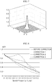
- FIG. 8 is a graph for explaining a reference for selecting a parameter value of a PSF according to an embodiment of the present invention.
- the indirect radiation detector has a higher DQE but lower sharpness (or a MTF) than the direct radiation detector. Accordingly, it is required to obtain high sharpness while maintaining the high DQE of the indirect radiation detector. Accordingly, when determining the parameters, in order to effectively determine the magnitude of the PSF and the sigma ⁇ of the Gaussian distribution, the MTF which is an index for checking the sharpness with reference to the image quality may be firstly checked.
- the image quality reference may include a condition that a value of the MTF for a spatial frequency of the correction image decreases according to an increase in spatial frequency, and the MTF value is the highest in the correction image according to the parameter value. It may be confirmed that in a graph of the radiation image (before correction), the MTF value decreases in a right downward direction as the spatial frequency increases. Like this, in the radiation image (before correction) including the blurring, when the spatial frequency increases, the blurring is amplified to decrease the MTF. However, unlike the obtained radiograph image (before correction), a graph of correction 3 does not have a right downward slope in a certain period (where the spatial frequency is about 0.7 lp/mm to about 1.4 lp/mm), but tilts upward.
- whether the unique features of the radiation image are distorted may be determined by determining whether the MTF graph does not have the right downward slope but tilts upward. Furthermore, whether the unique features of the radiation image are distorted may also be determined not only with the MTF graph but also with the NNPS and SNR graphs.
- a correction image having a highest MTF value among the correction images corrected according to the parameter value may be set as the image quality reference. For example, when the MTF value of the correction image is the highest, since the sharpness thereof is best, a correction image of which the sharpness is the best may be obtained among the correction images. However, since it is not good that the sharpness becomes so high to distort the unique features of the radiation image, a correction image having the highest MTF value may be selected from among the correction images of which the DQE value of the radiation image is maintained.
- a parameter may be determined so that the obtained radiation image may be deconvoluted with the correction image satisfying the foregoing condition.
- the correction image of which the unique features of the radiation image are not distorted and which has the highest sharpness may be obtained.
- a sharp radiation image may be obtained only with a small radiation dose and a radiation exposure dose of a subject may be reduced accordingly, more accurate diagnosis may be performed with the sharp radiation image.
- a very detailed part may be observed with a sharper radiation image in a process for observing microcalcification and breast masses, etc.
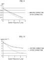
- FIG. 9 is a graph of an MTF for evaluating image quality according to an embodiment of the present invention
- FIG. 10 is a graph of an NNPS for evaluating image quality according to an embodiment of the present invention
- FIG. 11 is a graph of a DQE for evaluating image quality according to an embodiment of the present invention.
- the correction image for satisfying the image quality reference not only a graph of the MTF, which is a measurement factor of sharpness, but also a graph of the NNPS increases. Therefore, the DQE graph is not nearly changed.
- the correction image for satisfying the image quality reference has the same DQE as the radiation image before correction. This means that the unique features of the correction image are the same as those of the radiation image, and the unique features of the radiation image are not distorted by the correction. Accordingly, the radiation image, of which the sharpness is improved, may be obtained while characteristics of the indirect radiation detector, in which the DQE is high, are maintained, and accordingly, a sharp radiation image may be obtained with a small radiation dose.
- a radiation exposure dose of a subject may be reduced and more accurate diagnosis may be performed with the sharp radiation image.
- a sharper radiation image in a process for observing microcalcification and breast masses, etc.
- the image quality reference may include a condition that the DQE value of the correction image is in the range of 90% to 110% of the DQE value of the radiation image in the same spatial frequency.
- the DQE is obtained from the MTF, NNPS, and SNR. Accordingly, the DQE is for comprehensively evaluating the image quality by including the MTF, NNPS, and SNR, and may effectively determine whether the unique features of the image are distorted. Since a change in DQE due to correction of the radiation image means distortion of the unique features of the radiation image, the DQE value should not be changed. However, since it is difficult to equally maintain the DQE without an error while changing the MTF, an error range of ⁇ 10 % may be tolerated.
- the DQE graph of the correction image may be maintained in the same type as the obtained DQE graph of the radiograph image. Since there is a little difference in DQE value in this case, unique features of the correction image and the obtained radiation image may be determined as the same.
- the DQE graph of the correction image may vary differently from the obtained DQE graph of the radiograph image.
- the unique features of the correction image may be determined to be distorted.
- the correction image which does not satisfy the condition that the DQE value of the correction image is in the range of 90% to 110% of the DQE value of the radiation image in the same spatial frequency, is an image of which the unique features are distorted, it is worthless as an image for medical diagnosis. Therefore, the correction image necessarily satisfies the condition that the DQE value of the correction image is in the range of 90% to 110% of the DQE value of the radiation image in the same spatial frequency.
- the DQE value condition is a prerequisite that the correction image should satisfy
- the DQE since the DQE may be obtained from the MTF, NNPS, and SNT, the DQE value is not a value preferentially checked.
- the MTF from which the sharpness may be determined, may be firstly checked, and then distortion of the unique features of the radiation image may be estimated from the MTF graph.
- images for measuring the NNPS and MTF may be different from each other.
- the image for measuring the NNPS may be captured without a subject, and the image for measuring the MTF may be obtained by capturing an edge subject.
- the NNPS is for measuring and analyzing noise displayed as white in the image captured without an object.
- the MTF is for determining whether a subject portion is distinguished from a portion without the subject at the edge portion of the subject and for determining an extent of blurring. Through this, the NNPS and the MTF are measured, and the DQE may be calculated from the NNPS and MTF.
- An operation for classifying and storing the determined parameter values according to at least any one among the pixel size of the pixel array panel 120, the thickness of the scintillator panel 110, and the type of scintillator 111 is further included.
- operation S300 for correcting the radiation image by deconvoluting the radiation image from among the stored parameter values, the parameter value is selected according to at least any one among the pixel size of the pixel array panel 120, the thickness of the scintillator panel 110, and the type of scintillator 111, which are used for obtaining the radiation image, and the radiation image may be corrected.
- parameter data may be generated in advance according to at least one among the pixel size of the pixel array panel 120, the thickness of the scintillator panel 110, and the type of the scintillator 111.
- the parameter value which corresponds to at least any one among the pixel size of the pixel array panel 120, the thickness of the scintillator panel 110, and the type of the scintillator 111, is selected and applied to the PSF.
- the parameter data may be obtained by, before operation S100 for obtaining the radiation image, applying all the parameter values to each one among the pixel size of the pixel array panel 120, the thickness of the scintillator panel 110, and the type of the scintillator 111 to generate correction images, determining whether the correction images satisfy the image quality reference, and by storing the parameter values for allowing the correction images to satisfy the image quality reference according to at least any one among the pixel size of the pixel array panel 120, the thickness of the scintillator panel 110, and the type of the scintillator 111.
- combinations of corresponding parameter values may be obtained according to at least one among the pixel size of the pixel array panel 120, the thickness of the scintillator panel 110, and the type of the scintillator 111.
- a correction image of which unique features of the radiation image are not distorted while having the high MTF graph may be easily obtained.
- a parameter value satisfying the DQE condition and having a highest MTF value is searched while changing any one parameter and fixing other parameters, and for other parameters, parameter values satisfying the DQE condition and having a highest MTF value are searched in the same manner, and then a combination of parameter values, each having a highest MTF value and satisfying the DQE condition, may be obtained while the found parameter values are relatively changed.
- the magnitude of the PSF is necessary to be determined only to be equal to or greater than a prescribed magnitude (e.g., the magnitude that sufficiently includes the physical range of scattering), the magnitude of PSF may be firstly determined through evaluation of the image quality after fixing other parameters.
- the sigma ⁇ of the Gaussian distribution may be determined by using the determined magnitude of PSF, and other parameters may be determined such that the DQE condition is satisfied and the MTF value is a highest while the determined magnitude of PSF and the sigma ⁇ of the Gaussian distribution are fixed.
- the parameter value combination obtained like this may be the determined parameter values.
- the determined parameter values may be classified and stored according to at least one among the pixel size of the pixel array panel 120, the thickness of the scintillator panel 110, and the type of the scintillator 111, and the classified and stored parameter values may be the parameter data.
- the deconvolution may be iterated using the PSF to which the parameter values are applied, and the radiation image may be corrected.
- the parameter value combination is required not to distort the unique features of the radiation image for the correction image at the time of deconvoluting the obtained radiation image.
- the radiation image may be corrected to a correction image having a highest MTF graph among the correction images in which the unique features of the radiation image are not distorted by iterating deconvolution using the PSF to which the parameter values are applied.
- the correction image is necessary to satisfy the condition that the DQE value of the correction image is in the range of 90% to 110 % of the DQE value of the radiation image in the same spatial frequency.
- the extent of correction of the radiation image may be adjusted according to the magnitude of PSF, the shape of PSF, and the iteration number of deconvolution.
- the correction extent of the radiation image may be determined according to the shape and magnitude of PSF and the number of times of devolution.
- the number of iteration times of deconvolution may also be preset by checking a maximum number of times that the unique features of the radiation image are not distorted with the parameter value combinations.
- the parameter value combination and the maximum number of iterations may be pre-stored in a lookup table, etc. according to at least any one among the pixel size of the pixel array panel 120, the thickness of the scintillator panel 110, and the type of the scintillator 111.
- An operation for removing a fault element from the radiation image may be further included before the operation for correcting the radiation image by deconvoluting the radiation image.
- the fault element may include a flat field, a gain, and a defect.
- the defect may mainly influence the radiation image at the time of deconvoluting the radiation image.
- the defect is a part to which a pixel value is not properly output.
- the defect is amplified to exert bad influence on quality of the radiation image. Accordingly, the defect in the radiation image may be removed before the radiation image is corrected by deconvoluting the radiation image.
- the defect in a point/pixel type or a line type may be corrected using peripheral information.
- peripheral information since correction is performed using the peripheral information, a pixel value similar to an actual pixel value may be obtained and accordingly the quality of the radiation image may be improved.
- the defect is removed and accordingly, amplification of the defect may be prevented.
- a flat field correction and a gain correction may be performed as a preprocessing procedure of the radiation image.
- the flat field correction is to correct a difference in dose response of a pixel occurring by a hardware cause.
- the gain correction is to correct dose nonuniformity occurring by a radiation source.
- FIG. 12 is a cross-sectional view of a photodiode type indirect radiation detector according to another embodiment of the present invention
- FIG. 13 is a cross-sectional view of a charge-coupled device type indirect radiation detector according to another embodiment of the present invention.
- a radiographic system may include a radiation irradiating unit for irradiating a radiation 10 on a subject; an indirect radiation detector 100 which includes a scintillator panel 110 for converting the radiation 10 passing through the subject to be incident to visible light 11 and a pixel array panel 120 for storing charges generated by the visible light 11 in each pixel, and which realizes a radiation image according to a charge amount in each pixel; and an image processing unit for correcting the radiation image by deconvoluting the radiation image obtained by the indirect radiation detector 100 with an PSF.
- the radiation irradiating unit may adjust the intensity of the radiation 10 and irradiate the radiation 10 of the certain intensity on the subject to allow the radiation 10 passing through the subject to be incident into the scintillator panel 110.
- the indirect radiation detector 100 may include the scintillator panel 110.
- the radiation 10 incident to the scintillator panel 110 collides with the scintillator 111 to be converted to the visible light 11.
- the indirect radiation detector 100 may convert the intensity of the visible light 11 to an electrical signal through a thin film transistor 122 in which a photodiode 121 or a charge coupled device 120b is installed, and may realize an image with the electrical signal.
- the image processing unit may deconvolute a blurring of the radiation image, which occurs by light scattered by the scintillator 111 of the scintillator panel 110, with a PSF, and correct the blurring. Through this, the sharpness of the radiation image may be improved to enhance accuracy of medical diagnosis using the radiation image.
- the image processing unit may include a data storage unit in which parameter values, which are applied to a PSF according to at least any one among the pixel size of the pixel array panel 120, the thickness of the scintillator panel 110, and the type of the scintillator 111, are classified and stored according to at least any one among the pixel size of the pixel array panel 120, the thickness of the scintillator panel 110, and the type of the scintillator 111; a parameter selecting unit for selecting the parameter value according to at least any one among the pixel size of the pixel array panel 120, the thickness of the scintillator panel 110, and the type of the scintillator 111, and an image correcting unit for deconvoluting the radiation image using the PSF to which the selected parameter value is applied.
- the data storage unit may store combinations of the parameter values which are classified according to at least one among the pixel size of the pixel array panel 120, the thickness of the scintillator panel 110, and the type of the scintillator 111, and which satisfy a certain condition.
- the parameter value combinations are applied to the PSF to deconvolute the radiation image, a correction image in which unique features of the radiation image are not distorted and which has a high MTF graph may be obtained.
- the parameter values which correspond to at least any one among the pixel size of the pixel array panel 120, the thickness of the scintillator panel 110, and the type of the scintillator 111, may be easily selected.
- the parameter selecting unit may select a parameter value according to at least any one among the pixel size of the pixel array panel 120, the thickness of the scintillator panel 110, and the type of the scintillator 111.
- the parameter value may be selected according to at least any one among the pixel size of the pixel array panel 120, the thickness of the scintillator panel 110, and the type of the scintillator 111 by using the parameter values (i.e. parameter data), which stored in the data storage unit.
- the image correcting unit may correct the radiation image by deconvoluting the radiation image using the PSF to which the selected parameter value is applied.
- the correction may be performed to mitigate the blurring by convoluting a radiation image including a blurring with a sharp image to search a PSF which generates the same blurring as that in the radiation image, and by deconvoluting the radiation image including the blurring using the found PSF.
- the image processing unit may further include an iteration setting unit for setting the number of iterations for deconvoluting the radiation image.
- an iteration setting unit for setting the number of iterations for deconvoluting the radiation image.
- the deconvolution may be iterated to improve the sharpness of the radiation image.
- the iteration setting unit may allow the extent of correction of the radiation image to be adjusted according to the number of times of deconvolution.
- the number of times of deconvolution may also be preset by checking a maximum number of times that the unique features of the radiation image are not distorted with the parameter value combinations.
- the parameter value combination and the maximum number of iterations may be pre-stored in the data storage unit, such as a lookup table, according to at least any one among the pixel size of the pixel array panel 120, the thickness of the scintillator panel 110, and the type of the scintillator 111.
- the iteration setting unit may set the iteration number in order to satisfy the condition that the DQE value of the correction image, which is corrected by deconvoluting the radiation image with the PSF, is in the range of 90% to 110% of the DQE value of the radiation image in the same spatial frequency.
- the DQE value of the correction image is out of the range of 90% to 110% of the DQE value of the radiation image in the same spatial frequency, the unique features of the radiation image in the correction image are distorted. Accordingly, the DQE value of the correction image may be allowed to be in the range of 90% to 110% of the DQE value of the radiation image in the same spatial frequency.
- too many iteration of the deconvolution for improving the sharpness may cause distortion in unique features of the radiation image. Accordingly, the iteration number may be set in order to satisfy the condition that the DQE value of the correction image is in the range of 90% to 110% of the DQE value of the radiation image in the same spatial frequency.
- the image processing unit may further include a preprocessing unit for removing a fault element from the obtained radiation image.
- the preprocessing unit may preprocess the obtained radiation image.
- the fault element such as the defect may be amplified to exert a bad effect to the quality of the radiation image. Accordingly, the fault element such as defect in the radiation image may be removed before the radiation image is corrected by deconvoluting the radiation image.
- the fault element may include not only the defect but also a flat field and a gain, and the defect may mainly influence on the radiation image at the time of deconvoluting the radiation image.
- a blurring of a radiation image due to scatting of light generated in a scintillator panel of an indirect type radiation detector may be corrected by deconvoluting the radiation image with the PSF. Accordingly a radiation image of which the sharpness is improved with the indirect radiation detector may be obtained.
- a radiation image for which the sharpness is improved with the indirect radiation detector having a high DQE is obtained, a sharp radiation image may be obtained even with a small radiation dose. Accordingly, a radiation exposure dose of a subject may be lowered and more accurate diagnosis may be performed with the sharp radiation image.
- even a very detailed part may be observed with a sharper radiation image in a process for observing microcalcification and breast masses, etc.
Description
- The present invention relates to a radiation image processing method and a radiographic system, and in particular, to a radiation image processing method and a radiographic system capable of correcting a blurring due to light scattering occurring in a scintillator panel of an indirect radiation detector.
- Medical imaging using a radiation is performed on a subject matter through a Compton effect that only a portion of energy of a radiation photon is delivered to electrons or a photoelectric effect that all energy is delivered to electrons and a radiation is completely absorbed. At this point, typically a radiation having energy of 10 keV to 200 keV is used.
- Digital radiography devices for obtaining a radiation image are divided into an indirect type equipment and a direct type equipment. In the indirect type equipment, a radiation collides with a scintillator of a scintillator panel to generate a visible light ray, and the visible light ray is transformed to an image signal through a thin film transistor in which a charge coupled device (CCD) or a photodiode is installed. In addition, the direct type equipment obtains an image in a manner that a radiation passing through a subject is directly irradiated on a thin film transistor in which a photoconductor or a photoresistor is installed, and is transformed to an image signal.
- In such a radiographic system, a radiation radiated from a radiation generating device is irradiated on a wide area at once in a cone type and causes image distortion due to radiation scattering. As a method for removing such a scatter radiation, a method using an anti-scatter grid or an air gap is used.
- The grid method uses a difference between a primary radiation almost perpendicularly incident to a radiation detector and a scatter radiation incident in a random direction. This method is to dispose the anti-scatter grid between a subject and a radiation detector, and to physically cut off the scatter radiation, which is obliquely incident in a process where a radiation passing through the subject passes through the grid, from reaching the radiation detector. Here, the anti-scatter grid is composed of lead and aluminum.
- The method using the air gap is imaging with a space between a subject and a radiation detector. The scatter radiation is not perpendicularly but obliquely incident to the detector, and when there is the air gap between the detector and the subject, only the primary radiation among photons passing through the subject reaches the radiation detector. On the other hand, the scatter radiation is scattered to the surroundings and does not reach the radiation detector.
- However, in a case of adopting the indirect radiation detector using the scintillator panel, although the scatter radiation caused by the subject may be removed using these methods, scattering by the scintillator inside the radiation detector is not removed. In addition, when a radiation image is obtained by this radiographic system, a blurring may occur in the radiation image, thereby lowering the sharpness of the radiation image.
- [Patent Literature] Korean Patent Laid-open Publication No.
10-2012-0012736 - The scientific publication »«Jean Rinkel et al.: "Quantitative Digital Radiography Image Processing" in: "Photon-Based Medical Imagery", 13 February2013 (2013-02-13), John Wiley & Sons, Inc., Hoboken, NJ, USA, XP055150321, ISBN: 978-1-84-821241-1, pages 123-160, DOI: 10.1002/9781118601242.ch3« describes an image processing method comprising: (i) obtaining a radiation image using an indirect radiation detector comprising a scintillator panel and a pixel array panel; (ii) determining a parameter value for defining a point spread function (PSF) according to the scintillator panel or the pixel array panel; and (iii) correcting the radiation image by deconvoluting the radiation image using the PSF to which the parameter value is applied.
- The present invention provides a radiation image processing method and a radiographic system capable of correcting a blurring, which occurs due to scattering occurred in a scintillator panel of an indirect radiation detector, with deconvolution using a point spread function (PSF).
- According to an embodiment of the present invention, a radiation image processing method includes: obtaining a radiation image using an indirect radiation detector including a scintillator panel and a pixel array panel; determining a parameter value for defining a point spread function (PSF) according to the scintillator panel or the pixel array panel; and correcting the radiation image by deconvoluting the radiation image using the PSF to which the parameter value is applied.
- The radiation image processing method may further include removing a fault element from the radiation image before the correcting the radiation image by deconvoluting the radiation image.
- The parameter may define a magnitude of the PSF and a shape of the PSF.
- In the determining a parameter value, the parameter value may be determined to allow a correction image for which the radiation image is deconvoluted using the PSF to satisfy an image quality reference.
- The image quality may be evaluated by measuring at least any one selected from among a modulation transfer function (MTF), a detective quantum efficiency (DQE), a normalized noise power spectrum (NNPS), and a signal to noise ratio (SNR).
- The image quality reference may include a condition that a DQE value of the correction image is in a range of 90% to 110% of a DQE value of the radiation image in a same spatial frequency.
- The image quality reference may include a condition that for a spatial frequency of the correction image, a value of the MTF decreases according to an increase in spatial frequency, and the MTF value is a highest in the correction image according to the parameter value.
- The radiation image processing method may further include: classifying and storing the determined parameter value according to at least any one among a pixel size of the pixel array panel, a thickness of the scintillator panel, and a type of the scintillator, wherein in the correcting the radiation image by deconvoluting the radiation image, the radiation image is corrected by selecting a parameter value from among stored parameter values according to at least any one among the pixel size of the pixel array panel, the thickness of the scintillator panel, and the type of the scintillator, which are used for obtaining the radiation image.
- In the correcting the radiation image by deconvoluting the radiation image, the radiation image may be corrected by iterating the deconvolution using the PSF to which the parameter value is applied.
- According to another embodiment of the present invention, a radiographic system includes: a radiation irradiating unit irradiating a radiation on a subject; an indirect radiation detector including a scintillator panel converting a radiation, which passes through the subject and is incident thereto, to a visible light, and a pixel array panel storing charges generated by the visible light in each pixel, and realizing a radiation image according to a charge amount in each pixel; and an image processing unit correcting the radiation image by deconvoluting the radiation image obtained by the indirect radiation detector using a point spread function(PSF).
- The image processing unit may include: a data storage unit in which a parameter value, which is applied to the PSF according to at least any one among a pixel size of the pixel array panel, a thickness of the scintillator panel, and a type of the scintillator, is classified and stored according to at least any one among the pixel size of the pixel array panel, the thickness of the scintillator panel, and the type of the scintillator; a parameter selecting unit selecting the parameter value according to the at least any one among a pixel size of the pixel array panel, a thickness of the scintillator panel, and a type of the scintillator; and an image correcting unit deconvoluting the radiation image using the PSF to which the selected parameter value is applied.
- The image processing unit may further include a preprocessing unit removing a fault element from the obtained radiation image.
- The image processing unit may further include an iteration setting unit setting a number of times of deconvoluting the radiation image.
- The iteration setting unit may set an iteration number for satisfying a condition that a DQE value of a correction image, which is corrected by deconvoluting the radiation image with the PSF, is in a range of 90% to 110% of a DQE value of the radiation image in a same spatial frequency.
- A radiation image processing method according to an embodiment of the present invention may correct a blurring of a radiation image, which is caused by scatting of light generated in a scintillator panel of an indirect radiation detector, by deconvoluting the radiation image using a point spread function (PSF). Accordingly, a radiation image of which the sharpness is improved with an indirect radiation detector may be obtained. In addition, since a radiation image of which the sharpness is improved with the indirect radiation detector having a high detective quantum efficiency (DQE) is obtained, a sharp radiation image may be obtained even with a small radiation dose and accordingly, a radiation exposure dose of a subject may be lowered.
- In addition, artificial improvement in sharpness may be prevented and only a blurring may be corrected by evaluating image quality of a radiation image in which the blurring is corrected. In addition, a parameter value having highest sharpness and satisfying the image quality according to the thickness of the scintillator panel may be easily obtained by using parameter data.
- Furthermore, amplification of a defective element may be prevented in a process for correcting the blurring of the radiation image through preprocessing for removing the defective element before correcting the blurring of the radiation image. In addition, since the blurring is not artificially deleted but is mitigated to disappear, data information on the radiation image may be prevented from being lost.
-
-
FIG. 1 is a flowchart illustrating a radiation image processing method according to an embodiment of the present invention; -
FIG. 2 is a conceptual diagram illustrating a scattering degree of light in a thin scintillator panel according to an embodiment of the present invention; -
FIG. 3 is a conceptual diagram illustrating a scattering degree of light in a medium thickness scintillator panel according to an embodiment of the present invention; -
FIG. 4 is a conceptual diagram illustrating a scattering degree of light in a thick scintillator panel according to an embodiment of the present invention; -
FIG. 5 is a conceptual diagram illustrating the magnitude of a point spread function (PSF) in a pixel array panel in which a pixel size is large according to an embodiment of the present invention; -
FIG. 6 is a conceptual diagram illustrating the magnitude of a PSF in a pixel array panel in which a pixel size is small according to an embodiment of the present invention; -
FIG. 7 illustrates a PSF of Gaussian type according to an embodiment of the present invention; -
FIG. 8 is a graph for explaining a reference for selecting a parameter value of a PSF according to an embodiment of the present invention; -
FIG. 9 is a graph of a modulation transfer function (MTF) for evaluating image quality according to an embodiment of the present invention; -
FIG. 10 is a graph of a normalized noise power spectrum (NNPS) for evaluating image quality according to an embodiment of the present invention; -
FIG. 11 is a graph of a detective quantum efficiency (DQE) for evaluating image quality according to an embodiment of the present invention; -
FIG. 12 is a cross-sectional view of a photodiode type indirect radiation detector according to another embodiment of the present invention; and -
FIG. 13 is a cross-sectional view of a charge-coupled device type indirect radiation detector according to another embodiment of the present invention. - Hereinafter, specific embodiments will be described in detail with reference to the accompanying drawings. The present invention may, however, be embodied in different forms and should not be construed as limited to the embodiments set forth herein. Rather, these embodiments are provided so that this disclosure will be thorough and complete, and will fully convey the scope of the present invention to those skilled in the art. Throughout the drawings and written description, like reference numerals refer to like elements. In the drawings, the dimensions may be partially enlarged or exaggerated for clarity of illustration.
- A point spread function (PSF) depicts a shape that a point is represented by blurring in an image, and the extent of blurring may vary according to a shape of the PSF. For example, the larger the blurring area at each point in an image is, the blurring of the image gets more severe. Accordingly, the extent of blurring may be adjusted by adjusting the shape of the PSF, and using this, an image including the blurring may be obtained through convolution of a sharp image with the PSF.
- Accordingly, through this principle, a blurring effect may be applied to the sharp image. Besides, as in the present invention, a blurring of a radiation image may also be corrected by deconvoluting the radiation image with a PSF. Furthermore, when the radiation image including the blurring is corrected by performing deconvolution with the PSF, the blurring is not artificially deleted but is mitigated to disappear and accordingly data information on the radiation image may not be lost. Accordingly, when the radiation image is corrected, quality of the radiation image may not be lowered.
-
FIG. 1 is a flowchart illustrating a radiation image processing method according to an embodiment of the present invention. - Referring to
FIG. 1 , a radiation image processing method according to an embodiment of the present invention may include an operation S100 for obtaining a radiation image by using an indirect radiation detector, which includes ascintillator panel 110 and a pixel array panel 120; an operation S200 for determining a value of a parameter defining a PSF according to thescintillator panel 110 or the pixel array panel 120; and an operation S300 for correcting the radiation image by deconvoluting it with a PSF to which the parameter value is applied. - In order to process a radiation image, the radiation image is obtained (operation S100) using the indirect radiation detector including the
scintillator 110 and the pixel array panel 120. When the radiation image is obtained with the indirect radiation detector using thescintillator panel 110, a blurring occurs by light scattered by ascintillator 111 of thescintillator panel 110. At this point, the light scattering by thescintillator 111 may have a Gaussian shape. In order to correct the blurring and improve the sharpness of the radiation image, the radiation image including the blurring in the present invention is defined as an image for which a sharp image is convoluted with a PSF. In addition, the radiation image is corrected by deconvoluting the radiation image including the blurring using the PSF. - The pixel array panel 120 may store, for each pixel, charges generated by the visible light into which a radiation irradiated on the
scintillator panel 110 is converted. Here, the resolution of the radiation image may vary according to a pixel size of the pixel array panel 120. - In addition, the parameter value, which defines the PSF according to the
scintillator panel 110 or the pixel array panel 120, is determined (operation S200) in parallel with operation S100 for obtaining the radiation image. Operation S200 for determining the parameter value may be concurrently performed with operation S100 for obtaining the radiation image. Alternatively, the parameter value may be determined before or after operation S100 for obtaining the radiation image. Here, the parameter value for defining the PSF may be determined depending on thescintillator panel 110 or the pixel array panel 120. At this point, the parameter value for defining the PSF may be determined depending on the pixel size of the pixel array panel 120, the thickness of thescintillator panel 110, or the type of thescintillator 111. -
FIG. 2 is a conceptual diagram illustrating a scattering degree of light in a thin scintillator panel according to an embodiment of the present invention,FIG. 3 is a conceptual diagram illustrating a scattering degree of light in a medium thickness scintillator panel according to an embodiment of the present invention, andFIG. 4 is a conceptual diagram illustrating a scattering degree of light in a thick scintillator panel according to an embodiment of the present invention. - A line spread function (LSF) represents a distribution of a certain value one-dimensionally, and represents a distribution (or a difference in intensity) according to a position of
visible light 11 emitted from any onescintillator 111 inFIGS. 2 to 4 . Referring toFIGS. 2 to 4 , a scattering degree of light may be checked through the PSF and the greater the scattering degree of light is, the wider the sigma (or standard deviation) of the LSF is. Accordingly, it may be seen throughFIGS. 2 to 4 that the thicker thescintillator panel 110 is, the more the scattering of light is. Here, the narrower the sigma of the LSF is, the sharper the radiation image is, and accordingly, the wider the sigma of the LSF is, the greater the scattering degree of light is. In other words, as the thickness of thescintillator panel 110 is thicker, a conversion efficiency that theradiation 10 is converted tovisible light 11 becomes higher. However, when scattering of light is increased according to the conversion efficiency, it causes a more severe blurring of the radiation image. - The scattering degree of light may vary according not only to the thickness of the
scintillator panel 110 but also to the type of the scintillator panel 110 (or scintillator 111). From theFIGS. 2 to 4 , thestraightly incident radiation 10 collides with thescintillator 111 and is emitted from thescintillator 111 as thevisible light 11 in all directions. The blurring occurs in the radiation image by thevisible light 11 incident not perpendicularly but diagonally among thevisible light 11 emitted in all directions. When the conversion efficiency for converting theradiation 10 to thevisible light 11 becomes better according to the type of the scintillator 111 (or the type of the scintillator panel), the light scattering is increased to cause more severe blurring. - Furthermore, the blurring of the radiation image may vary according to the intensity of the
radiation 10 incident to thescintillator panel 110. When theradiation 10 of lower energy is incident to thescintillator panel 110 and the thickness of thescintillator panel 110 is thick, the light scattering is increased. In this case, since the blurring becomes severe in the radiation image, a spatial resolution is reduced but a speed becomes increased. On the other hand, when theradiation 10 of high energy is incident to thescintillator panel 110, since a probability that theradiation 10 reacts to thescintillator 111 becomes high as the thickness of thescintillator panel 110 becomes thicker, the spatial resolution may become better. In other words, since there is the proper thickness of thescintillator panel 110 according to the intensity of theradiation 10, when the thickness of thescintillator panel 110 is thinner than the proper one, the spatial resolution becomes bad. When the thickness of thescintillator panel 110 is thicker than the proper one, the light scattering is increased to make the blurring of the radiation image more severe. -
FIG. 5 is a conceptual diagram illustrating the magnitude of a PSF in a pixel array panel in which a pixel size is large according to an embodiment of the present invention, andFIG. 6 is a conceptual diagram illustrating the magnitude of a PSF in a pixel array panel in which a pixel size is small according to an embodiment of the present invention. - Referring to
FIGS. 5 and 6 , the resolution of the radiation image may vary according to the pixel size of the pixel array panel 120.FIGS. 5 and 6 have the same shadow area, butFIG. 5 does not represent well light and darkness for each position because of a large pixel size. However, inFIG. 6 , since the pixel size is smaller than that ofFIG. 5 , the light and darkness of a peripheral portion may be represented low to show the light and darkness for each position relatively well. Like this, the smaller the pixel size is, the higher the resolution is. - The parameter may define the magnitude of the PSF and the shape of the PSF. Here, the magnitude and shape of the PSF are parameters for depicting a scattering type of light in a situation in which the scattering type of light is quantized by the
scintillator panel 110 and converted to a digital signal. - The magnitude of the PSF may mean the number of pixels (or the size of a matrix) having a digital value, and may correspond to the number of pixels corresponding to an area on which a point of light is scattered by the
scintillator panel 110. Accordingly, for thesame scintillator panel 110, when the pixel size of the pixel array panel 120 is large, since the number of pixels corresponding to the area on which the point of light is scattered by thescintillator panel 110 is smaller than that in a case where the pixel size of the pixel array panel 120 is small, the size of the PSF may be relatively smaller. Since the magnitude of the PSF is required to be sufficiently large to include the area on which the light is scattered by thescintillator panel 110, the magnitude of the PSF may vary according to the pixel size of the pixel array panel 120. - The shape of the PSF may be that of a graph formed by each pixel value (or matrix value) of the PSF. The shape of the PSF may be determined by a matrix of the PSF. A variation amount of the brightness of an image may vary for each area according to the shape (or matrix) of the PSF. Through this, various blurring effects may be obtained by applying the PSF to a sharp image, and correction may be effectively performed according to a blurring type by varying the shape of the PSF and performing deconvolution according to a blurring shape of a radiation image.
- In an embodiment of the present invention, the PSF shape may be a Gaussian shape. For example, when the
radiation 10 collides with thescintillator 111, since visual light is radiated from thescintillator 111 in all directions, it may be effective to determine the shape of the PSF as a Gaussian shape which may represent dispersion well from one point to all directions. However, the PSF shape is not limited thereto and may be determined according to the blurring type of the radiation image. - In a case where the PSF shape is the Gaussian shape, the Gaussian shape may be determined by sigma σ of the Gaussian distribution and the sigma σ of the Gaussian distribution may be used as one of the parameters. Accordingly, in the PSF of the Gaussian shape, the magnitude of the PSF and the sigma σ of the Gaussian distribution may be used as the parameters.
- The PSF of the Gaussian shape may be expressed as the following Equation (1)

- In Equation (1), x and y denote x and y coordinates, σ denotes sigma of the Gaussian distribution, and when x, y, and σ are substituted for Equation (1), a Gaussian value at (x, y) coordinates may be obtained.
- Furthermore, the thicker the thickness of the
scintillator panel 110 is, the magnitude of the PSF and the sigma σ of the Gaussian distribution may increase, and a blurring area may be increased since thevisible light 11 emitted from thescintillator 111 in all directions may be dispersed wider before being incident to thephotodiode 121. Accordingly, since the magnitude of the PSF may be increased and the sigma σ of the Gaussian distribution may be increased according to the magnitude of the PSF, the blurring may be effectively depicted through the PSF. In addition, the magnitude and shape of the PSF may be obtained by expanding an LSF two-dimensionally after obtaining the LSF in one dimension from an edge image. - Like this, the magnitude of the PSF may vary according to the pixel size of the pixel array panel 120, the thickness of the
scintillator panel 110, and the type of thescintillator 111, and when the magnitude of the PSF is determined, the sigma σ of the Gaussian distribution may vary according to the thickness of thescintillator panel 110 and the type of thescintillator 111. Accordingly, in the present invention, the magnitude of the PSF and the sigma σ of the Gaussian distribution may be obtained according to the pixel size of the pixel array panel 120, the thickness of thescintillator panel 110, and the type of thescintillator 111, and accordingly, a radiation image having the best sharpness may be obtained with effective correction. - Next, the radiation image is corrected by deconvoluted using the PSF, to which the parameter values are applied(operation S300). Once the parameter values are known, the radiation image may be deconvoluted with the PSF to correct the radiation image. Under assumption that an image including the blurring is generated by convoluting the PSF with a sharp image, the deconvolution process may be performed by iterating an algorithm until a residual error value between a blurred image obtained from capturing (namely, including light scattering by the scintillator) and a blurred image estimated by a user becomes sufficiently small. As the deconvolution, a spatial-invariant deconvolution for recovering the entire image using one PSF may be used. Alternatively, a spatial-variant deconvolution for recovering an image using multiple individual PSFs according to an image position may also be used. Although the spatial-variant deconvolution, in which an individual PSF is used properly to each position, may have higher sharpness than the spatial-invariant deconvolution, since a process for obtaining the individual PSF proper to each position is complicated, the spatial-invariant deconvolution may be mainly used.
- The indirect radiation detector has a higher Detective Quantum Efficiency (DQE) but lower sharpness (or an MTF) than the direct radiation detector. Here, the DQE is a radiation conversion efficiency, and means that a good image may be obtained using a smaller radiation dose when the DQE becomes higher. Accordingly, when the indirect radiation detector is used in the present invention, scintillator scattering occurring due to a structural feature of hardware may be corrected with a software algorithm to obtain high sharpness similar to that in the direct radiation detector while maintaining the high DQE of the indirect radiation detector.
- As a result of performing the algorithm according to the present invention, an image may be obtained which has a higher DQE than that of the direct radiation detector, while having high sharpness. In this case, a sharper image of high quality may be obtained with a smaller radiation dose. In other words, in a case of being used in a product having a high DQE, since the radiation dose becomes smaller, a radiation exposure dose to a subject becomes lowered, and since a sharper image may be obtained when the sharpness is high, it is useful to diagnosis.
- In particular, in mammography, even a very detailed part may be observed with a sharper radiation image in a process for observing microcalcification and breast masses, etc.
- Furthermore, in the present invention, it is assumed that the thickness of the
scintillator panel 110 is uniform across the entire region of the radiation detector and a difference in thickness is not large, recovery may be performed by deconvolution using one PSF and the obtained image. In this process, image measurement evaluation factors such as the NNPS and DQE may vary according to a radiation dose irradiated at the time of obtaining the image. However, an increase in MTF according to the present invention does not influence the radiation dose. The MTF is influenced by the pixel size of the pixel array panel 120 and the structure (e.g. a needle structure of Csl) of thescintillator panel 110. Accordingly, in the present invention, the MTF, which is lowered by the structure of thescintillator panel 110, may be recovered to improve the sharpness of the radiation image. Like this, an effect due to scattering of light generated in thescintillator panel 110 may determined through the MTF which is not influenced by the radiation dose, instead of variables influenced by the radiation dose such as the NNPS for determining a noise component and the DQE for determining the entire performance. In addition, the sharpness of the radiation image may be improved by enhancing the MTF. In addition, the MTF is proper as a factor for measuring the sharpness of the radiation image since it is not influenced by the radiation dose. Accordingly, in the present invention, the sharpness of the radiation image is measured through the MTF and is improved by enhancing the MTF. When the factor for measuring the sharpness of the radiation image is influenced by the radiation dose, it becomes difficult to measure the sharpness of the radiation image. However, in the present invention, the sharpness of the radiation image may be measured without any difficulty by using the MTF, which is not influenced by the radiation dose, as the measuring factor, and may be improved by enhancing the MTF. -
FIG. 7 illustrates a PSF of Gaussian type according to an embodiment of the present invention. - Referring to
Fig. 7 , scales in dotted lines denote an x-axis, a y-axis, and a pixel value (or a z-axis value) in an image, the total area of the pixels divided with solid lines becomes the magnitude of PSF, and combinations of pixel values become a matrix of the PSF. Here, the pixel value may be a brightness value of each pixel. - When the sharp image is convoluted with the PSF having such a Gaussian shape, a blurring may occur around the center portion of the Gaussian distribution. In addition, when the radiation image including the blurring is deconvoluted with such a Gaussian type PSF, the blurring occurring around the center portion of the Gaussian distribution is mitigated to correct the radiation image.
- In operation S200 for determining the parameter value, a correction image for which the radiation image is deconvoluted with the PSF may be determined as a parameter value for satisfying the image quality reference. When the radiation image is corrected by deconvolution, the sharpness of the correction image may be enhanced than that of the radiation image. However, when the sharpness is excessively artificially enhanced, unique features of the radiation image become distorted. In addition, when the unique features of the radiation image are distorted, since the radiation image becomes worthless, the correction image of which unique features are distorted may be filtered out by evaluating the quality of the correction image and determining whether the unique features of the radiation image are distorted. Accordingly, when the parameter value is determined as a parameter value for satisfying the image quality reference, the radiation image may be corrected to the correction image of which the sharpness is enhanced without distorting the unique features of the radiation image.
- The image quality may be evaluated by measuring at least any one selected from among the MTF, the DQE, the NNPS, and a signal to noise ratio (SNR). The values of the MTF, DQE, NNPS, and SNR may be measured with an image evaluation tool by analyzing a feature graph of each measurement value to evaluate the image quality. In other words, whether the unique features of the radiation image are distorted may be determined through the feature graph of each measurement value.
- The Modulation Transfer Function (MTF) represents a frequency response of any one image system and is a sharpness related measurement factor which may be defined as an image contrast ratio for a subject contrast. In addition, the MTF is a frequency recording capability for a region corresponding to each frequency when a spatial frequency of an image is measured, and the resolution of the image may be obtained by marking a degree that a radiographic system reacts to a spatial variation of the image. The MTF is frequently used for evaluating the sharpness of an image and whether the sharpness is enhanced may be determined through the MTF.
- The DQE represents a transfer feature of the SNR and is a parameter for representing a noise amount occurring by a last image. In other words, it measures the overall SNR performance of a radiation detector, and a capability of a radiation detector for transferring the SNR. In addition, the DQE may be defined as the square of a ratio of an output SNR to an input SNR, and may be expressed as Equation (2).

- In addition, the DQE is a comprehensive index for indicating quality of a radiation image and is obtained by the MTF, NNPS, and SNR. Accordingly, the image quality may be comprehensively evaluated with the MTF. NNPS, and SNR, and whether the unique features of the image are distorted may be effectively determined.
- The noise power spectrum (NPS) is representation of a distribution of dispersion value of noise on a spatial frequency, represents dependence of noise on the spatial frequency, which is a variation factor between pixels in an image, and is a noise related measurement factor. And, the Normalized Noise Power Spectrum (NNPS) is a normalized NPS and may be obtained by averaging all spectrum samples.
- Image noise means uncertainty or inaccuracy in an image signal, and may be divided into noise resulted from the number of photons forming image information and noise caused by an image signal processing circuit. For the former, a degree of the uncertainty increases when the number of photons forming the image information is small. On the other hand, when the number of photons increases, a probability to be detected as an image signal may become high to reduce a noise effect to the image signal. In order to evaluate the SNR of the radiographic system, an image may be obtained using a lead phantom from which the central portion is removed, and may use gray-scale value of the obtained image, which is measured along a leader line. The image signal means a difference ΔD between a peripheral lead phantom and a gray-scale value in a circular region of the center, and the image noise means a standard deviation s of the gray-scale value of the obtained image. A ratio of them (ΔD/s) may be defined as the SNR which is a measurement factor related to the signal and noise.
-
FIG. 8 is a graph for explaining a reference for selecting a parameter value of a PSF according to an embodiment of the present invention. - The indirect radiation detector has a higher DQE but lower sharpness (or a MTF) than the direct radiation detector. Accordingly, it is required to obtain high sharpness while maintaining the high DQE of the indirect radiation detector. Accordingly, when determining the parameters, in order to effectively determine the magnitude of the PSF and the sigma σ of the Gaussian distribution, the MTF which is an index for checking the sharpness with reference to the image quality may be firstly checked.
- Referring to
FIG. 8 , the image quality reference may include a condition that a value of the MTF for a spatial frequency of the correction image decreases according to an increase in spatial frequency, and the MTF value is the highest in the correction image according to the parameter value. It may be confirmed that in a graph of the radiation image (before correction), the MTF value decreases in a right downward direction as the spatial frequency increases. Like this, in the radiation image (before correction) including the blurring, when the spatial frequency increases, the blurring is amplified to decrease the MTF. However, unlike the obtained radiograph image (before correction), a graph ofcorrection 3 does not have a right downward slope in a certain period (where the spatial frequency is about 0.7 lp/mm to about 1.4 lp/mm), but tilts upward. From the graph ofcorrection 3, it may be estimated that the unique features of the radiograph image are distorted. In order to verify this, the DQE may be analyzed. From the graph ofcorrection 3 of which the shape is greatly changed, it may be seen that a difference occurs between DQE values of the correction image and the radiation image, and the unique features thereof are distorted. Although a graph ofcorrection 2 is slightly changed in shape from the radiation image (before correction), it has a right downward slop. From the analysis of the graph ofcorrection 2, it may be seen that the correction image maintains the DQE value of the radiation image and the unique features of the radiation image are not distorted. Like this, whether the unique features of the radiation image are distorted may be determined through the graph of the MTF. In other words, whether the unique features of the radiation image are distorted may be determined by determining whether the MTF graph does not have the right downward slope but tilts upward. Furthermore, whether the unique features of the radiation image are distorted may also be determined not only with the MTF graph but also with the NNPS and SNR graphs. - In addition, a correction image having a highest MTF value among the correction images corrected according to the parameter value may be set as the image quality reference. For example, when the MTF value of the correction image is the highest, since the sharpness thereof is best, a correction image of which the sharpness is the best may be obtained among the correction images. However, since it is not good that the sharpness becomes so high to distort the unique features of the radiation image, a correction image having the highest MTF value may be selected from among the correction images of which the DQE value of the radiation image is maintained. In addition, a parameter may be determined so that the obtained radiation image may be deconvoluted with the correction image satisfying the foregoing condition. Accordingly, the correction image of which the unique features of the radiation image are not distorted and which has the highest sharpness may be obtained. Like this, in the present invention, since a sharp radiation image may be obtained only with a small radiation dose and a radiation exposure dose of a subject may be reduced accordingly, more accurate diagnosis may be performed with the sharp radiation image. In particular, in mammography, even a very detailed part may be observed with a sharper radiation image in a process for observing microcalcification and breast masses, etc.
-
FIG. 8 is a graph obtained by changing the sigma σ of the Gaussian distribution while fixing the magnitude of the Gaussian type PSF, and a graph ofcorrection 1 is for the case where σ = 0.5, a graph ofcorrection 2 is for the case where σ =0.7, and a graph ofcorrection 3 is for the case where σ =1.0. From among the graphs ofcorrection 1, correction2, andcorrection 3, the graph ofcorrection 2 may be selected. The reason is because although the graph ofcorrection 3 has a highest MTF value, the unique features of the radiation image are distorted. Therefore, the graph ofcorrection 2 having a higher MTF value is selected from between the graphs of which the unique features of the radiation image are not distorted. Accordingly, the sigma σ of the Gaussian distribution may be determined as 0.7, and the fixed magnitude of the PSF may be determined as the parameter value. Furthermore, other parameter values may be determined through experiments according to the above-described methods. -
FIG. 9 is a graph of an MTF for evaluating image quality according to an embodiment of the present invention,FIG. 10 is a graph of an NNPS for evaluating image quality according to an embodiment of the present invention, andFIG. 11 is a graph of a DQE for evaluating image quality according to an embodiment of the present invention. - Referring to
FIGS. 9 to 11 , in the correction image for satisfying the image quality reference, not only a graph of the MTF, which is a measurement factor of sharpness, but also a graph of the NNPS increases. Therefore, the DQE graph is not nearly changed. As a result, the correction image for satisfying the image quality reference has the same DQE as the radiation image before correction. This means that the unique features of the correction image are the same as those of the radiation image, and the unique features of the radiation image are not distorted by the correction. Accordingly, the radiation image, of which the sharpness is improved, may be obtained while characteristics of the indirect radiation detector, in which the DQE is high, are maintained, and accordingly, a sharp radiation image may be obtained with a small radiation dose. Through this, a radiation exposure dose of a subject may be reduced and more accurate diagnosis may be performed with the sharp radiation image. In particular, in mammography, even a very detailed part may be observed with a sharper radiation image in a process for observing microcalcification and breast masses, etc. - The image quality reference may include a condition that the DQE value of the correction image is in the range of 90% to 110% of the DQE value of the radiation image in the same spatial frequency. The DQE is obtained from the MTF, NNPS, and SNR. Accordingly, the DQE is for comprehensively evaluating the image quality by including the MTF, NNPS, and SNR, and may effectively determine whether the unique features of the image are distorted. Since a change in DQE due to correction of the radiation image means distortion of the unique features of the radiation image, the DQE value should not be changed. However, since it is difficult to equally maintain the DQE without an error while changing the MTF, an error range of ± 10 % may be tolerated. When the DQE value of the correction image is in the range of 90% to 110% of the DQE value of the radiation image in the same spatial frequency, the DQE graph of the correction image may be maintained in the same type as the obtained DQE graph of the radiograph image. Since there is a little difference in DQE value in this case, unique features of the correction image and the obtained radiation image may be determined as the same. On the other hand, when the DQE value of the correction image is out of the range of 90% to 110% of the DQE value of the radiation image in the same spatial frequency, the DQE graph of the correction image may vary differently from the obtained DQE graph of the radiograph image. In addition, since the difference in DQE value is large, the unique features of the correction image may be determined to be distorted. Like this, since the correction image, which does not satisfy the condition that the DQE value of the correction image is in the range of 90% to 110% of the DQE value of the radiation image in the same spatial frequency, is an image of which the unique features are distorted, it is worthless as an image for medical diagnosis. Therefore, the correction image necessarily satisfies the condition that the DQE value of the correction image is in the range of 90% to 110% of the DQE value of the radiation image in the same spatial frequency.
- Although the DQE value condition is a prerequisite that the correction image should satisfy, since the DQE may be obtained from the MTF, NNPS, and SNT, the DQE value is not a value preferentially checked. For example, the MTF, from which the sharpness may be determined, may be firstly checked, and then distortion of the unique features of the radiation image may be estimated from the MTF graph. However, it is necessary to check the DQE in order to accurately determine whether the unique features of the radiation image are distorted.
- Furthermore, images for measuring the NNPS and MTF may be different from each other. The image for measuring the NNPS may be captured without a subject, and the image for measuring the MTF may be obtained by capturing an edge subject. The NNPS is for measuring and analyzing noise displayed as white in the image captured without an object. In addition, the MTF is for determining whether a subject portion is distinguished from a portion without the subject at the edge portion of the subject and for determining an extent of blurring. Through this, the NNPS and the MTF are measured, and the DQE may be calculated from the NNPS and MTF.
- An operation for classifying and storing the determined parameter values according to at least any one among the pixel size of the pixel array panel 120, the thickness of the
scintillator panel 110, and the type ofscintillator 111 is further included. In operation S300 for correcting the radiation image by deconvoluting the radiation image, from among the stored parameter values, the parameter value is selected according to at least any one among the pixel size of the pixel array panel 120, the thickness of thescintillator panel 110, and the type ofscintillator 111, which are used for obtaining the radiation image, and the radiation image may be corrected. A lot of time are necessary to verify whether a correction image, for which the radiation image is deconvolutioned with a PSF to which the parameter values are applied, satisfies the image quality reference. Accordingly, parameter data may be generated in advance according to at least one among the pixel size of the pixel array panel 120, the thickness of thescintillator panel 110, and the type of thescintillator 111. In addition, the parameter value, which corresponds to at least any one among the pixel size of the pixel array panel 120, the thickness of thescintillator panel 110, and the type of thescintillator 111, is selected and applied to the PSF. - The parameter data may be obtained by, before operation S100 for obtaining the radiation image, applying all the parameter values to each one among the pixel size of the pixel array panel 120, the thickness of the
scintillator panel 110, and the type of thescintillator 111 to generate correction images, determining whether the correction images satisfy the image quality reference, and by storing the parameter values for allowing the correction images to satisfy the image quality reference according to at least any one among the pixel size of the pixel array panel 120, the thickness of thescintillator panel 110, and the type of thescintillator 111. Accordingly, through the parameter data, combinations of corresponding parameter values may be obtained according to at least one among the pixel size of the pixel array panel 120, the thickness of thescintillator panel 110, and the type of thescintillator 111. In addition, a correction image of which unique features of the radiation image are not distorted while having the high MTF graph may be easily obtained. - Furthermore, a parameter value satisfying the DQE condition and having a highest MTF value is searched while changing any one parameter and fixing other parameters, and for other parameters, parameter values satisfying the DQE condition and having a highest MTF value are searched in the same manner, and then a combination of parameter values, each having a highest MTF value and satisfying the DQE condition, may be obtained while the found parameter values are relatively changed. At this point, since the magnitude of the PSF is necessary to be determined only to be equal to or greater than a prescribed magnitude (e.g., the magnitude that sufficiently includes the physical range of scattering), the magnitude of PSF may be firstly determined through evaluation of the image quality after fixing other parameters. Next, the sigma σ of the Gaussian distribution may be determined by using the determined magnitude of PSF, and other parameters may be determined such that the DQE condition is satisfied and the MTF value is a highest while the determined magnitude of PSF and the sigma σ of the Gaussian distribution are fixed. The parameter value combination obtained like this may be the determined parameter values. In addition, the determined parameter values may be classified and stored according to at least one among the pixel size of the pixel array panel 120, the thickness of the
scintillator panel 110, and the type of thescintillator 111, and the classified and stored parameter values may be the parameter data. - In operation S300 for correcting the radiation image by deconvoluting the radiation image, the deconvolution may be iterated using the PSF to which the parameter values are applied, and the radiation image may be corrected. The parameter value combination is required not to distort the unique features of the radiation image for the correction image at the time of deconvoluting the obtained radiation image. Through this combination, even when the MTF graph is not high, the radiation image may be corrected to a correction image having a highest MTF graph among the correction images in which the unique features of the radiation image are not distorted by iterating deconvolution using the PSF to which the parameter values are applied. At this point, in order for the unique features of the radiation image not to be distorted, the correction image is necessary to satisfy the condition that the DQE value of the correction image is in the range of 90% to 110 % of the DQE value of the radiation image in the same spatial frequency. Like this, the extent of correction of the radiation image may be adjusted according to the magnitude of PSF, the shape of PSF, and the iteration number of deconvolution. In other words, the correction extent of the radiation image may be determined according to the shape and magnitude of PSF and the number of times of devolution. Furthermore, through advance experiments, the number of iteration times of deconvolution may also be preset by checking a maximum number of times that the unique features of the radiation image are not distorted with the parameter value combinations. In addition, the parameter value combination and the maximum number of iterations may be pre-stored in a lookup table, etc. according to at least any one among the pixel size of the pixel array panel 120, the thickness of the
scintillator panel 110, and the type of thescintillator 111. - An operation for removing a fault element from the radiation image may be further included before the operation for correcting the radiation image by deconvoluting the radiation image. The fault element may include a flat field, a gain, and a defect. Among them, the defect may mainly influence the radiation image at the time of deconvoluting the radiation image. The defect is a part to which a pixel value is not properly output. When there is a defect in the radiation image at the time of deconvoluting the radiation image, the defect is amplified to exert bad influence on quality of the radiation image. Accordingly, the defect in the radiation image may be removed before the radiation image is corrected by deconvoluting the radiation image.
- At the time of removing the defect, the defect in a point/pixel type or a line type may be corrected using peripheral information. In this case, since correction is performed using the peripheral information, a pixel value similar to an actual pixel value may be obtained and accordingly the quality of the radiation image may be improved. In addition, the defect is removed and accordingly, amplification of the defect may be prevented.
- In addition, a flat field correction and a gain correction may be performed as a preprocessing procedure of the radiation image. The flat field correction is to correct a difference in dose response of a pixel occurring by a hardware cause. In addition, the gain correction is to correct dose nonuniformity occurring by a radiation source.
-
FIG. 12 is a cross-sectional view of a photodiode type indirect radiation detector according to another embodiment of the present invention, andFIG. 13 is a cross-sectional view of a charge-coupled device type indirect radiation detector according to another embodiment of the present invention. - Descriptions will be provided about a radiographic system according to another embodiment with reference to
FIGS. 12 and13 , and repetitive descriptions with the foregoing descriptions related to the radiation image processing method according to the embodiment will be omitted. - A radiographic system according to another embodiment may include a radiation irradiating unit for irradiating a
radiation 10 on a subject; anindirect radiation detector 100 which includes ascintillator panel 110 for converting theradiation 10 passing through the subject to be incident tovisible light 11 and a pixel array panel 120 for storing charges generated by thevisible light 11 in each pixel, and which realizes a radiation image according to a charge amount in each pixel; and an image processing unit for correcting the radiation image by deconvoluting the radiation image obtained by theindirect radiation detector 100 with an PSF. - The radiation irradiating unit may adjust the intensity of the
radiation 10 and irradiate theradiation 10 of the certain intensity on the subject to allow theradiation 10 passing through the subject to be incident into thescintillator panel 110. - The
indirect radiation detector 100 may include thescintillator panel 110. Theradiation 10 incident to thescintillator panel 110 collides with thescintillator 111 to be converted to thevisible light 11. Here, theindirect radiation detector 100 may convert the intensity of thevisible light 11 to an electrical signal through athin film transistor 122 in which aphotodiode 121 or a charge coupleddevice 120b is installed, and may realize an image with the electrical signal. - The image processing unit may deconvolute a blurring of the radiation image, which occurs by light scattered by the
scintillator 111 of thescintillator panel 110, with a PSF, and correct the blurring. Through this, the sharpness of the radiation image may be improved to enhance accuracy of medical diagnosis using the radiation image. - The image processing unit may include a data storage unit in which parameter values, which are applied to a PSF according to at least any one among the pixel size of the pixel array panel 120, the thickness of the
scintillator panel 110, and the type of thescintillator 111, are classified and stored according to at least any one among the pixel size of the pixel array panel 120, the thickness of thescintillator panel 110, and the type of thescintillator 111; a parameter selecting unit for selecting the parameter value according to at least any one among the pixel size of the pixel array panel 120, the thickness of thescintillator panel 110, and the type of thescintillator 111, and an image correcting unit for deconvoluting the radiation image using the PSF to which the selected parameter value is applied. - The data storage unit may store combinations of the parameter values which are classified according to at least one among the pixel size of the pixel array panel 120, the thickness of the
scintillator panel 110, and the type of thescintillator 111, and which satisfy a certain condition. When the parameter value combinations are applied to the PSF to deconvolute the radiation image, a correction image in which unique features of the radiation image are not distorted and which has a high MTF graph may be obtained. In addition, the parameter values, which correspond to at least any one among the pixel size of the pixel array panel 120, the thickness of thescintillator panel 110, and the type of thescintillator 111, may be easily selected. - The parameter selecting unit may select a parameter value according to at least any one among the pixel size of the pixel array panel 120, the thickness of the
scintillator panel 110, and the type of thescintillator 111. Here, the parameter value may be selected according to at least any one among the pixel size of the pixel array panel 120, the thickness of thescintillator panel 110, and the type of thescintillator 111 by using the parameter values (i.e. parameter data), which stored in the data storage unit. - The image correcting unit may correct the radiation image by deconvoluting the radiation image using the PSF to which the selected parameter value is applied. The correction may be performed to mitigate the blurring by convoluting a radiation image including a blurring with a sharp image to search a PSF which generates the same blurring as that in the radiation image, and by deconvoluting the radiation image including the blurring using the found PSF.
- The image processing unit may further include an iteration setting unit for setting the number of iterations for deconvoluting the radiation image. When the sharpness is slightly improved with one time deconvolution, the deconvolution may be iterated to improve the sharpness of the radiation image. Like this, the iteration setting unit may allow the extent of correction of the radiation image to be adjusted according to the number of times of deconvolution. Furthermore, through advance experiments, the number of times of deconvolution may also be preset by checking a maximum number of times that the unique features of the radiation image are not distorted with the parameter value combinations. In addition, the parameter value combination and the maximum number of iterations may be pre-stored in the data storage unit, such as a lookup table, according to at least any one among the pixel size of the pixel array panel 120, the thickness of the
scintillator panel 110, and the type of thescintillator 111. - The iteration setting unit may set the iteration number in order to satisfy the condition that the DQE value of the correction image, which is corrected by deconvoluting the radiation image with the PSF, is in the range of 90% to 110% of the DQE value of the radiation image in the same spatial frequency. When the DQE value of the correction image is out of the range of 90% to 110% of the DQE value of the radiation image in the same spatial frequency, the unique features of the radiation image in the correction image are distorted. Accordingly, the DQE value of the correction image may be allowed to be in the range of 90% to 110% of the DQE value of the radiation image in the same spatial frequency. However, too many iteration of the deconvolution for improving the sharpness may cause distortion in unique features of the radiation image. Accordingly, the iteration number may be set in order to satisfy the condition that the DQE value of the correction image is in the range of 90% to 110% of the DQE value of the radiation image in the same spatial frequency.
- The image processing unit may further include a preprocessing unit for removing a fault element from the obtained radiation image. The preprocessing unit may preprocess the obtained radiation image. When there is a fault element such as a defect in the radiation image at the time of deconvolution of the radiation image, the fault element such as the defect may be amplified to exert a bad effect to the quality of the radiation image. Accordingly, the fault element such as defect in the radiation image may be removed before the radiation image is corrected by deconvoluting the radiation image. The fault element may include not only the defect but also a flat field and a gain, and the defect may mainly influence on the radiation image at the time of deconvoluting the radiation image.
- Like this, a blurring of a radiation image due to scatting of light generated in a scintillator panel of an indirect type radiation detector may be corrected by deconvoluting the radiation image with the PSF. Accordingly a radiation image of which the sharpness is improved with the indirect radiation detector may be obtained. In addition, since a radiation image for which the sharpness is improved with the indirect radiation detector having a high DQE is obtained, a sharp radiation image may be obtained even with a small radiation dose. Accordingly, a radiation exposure dose of a subject may be lowered and more accurate diagnosis may be performed with the sharp radiation image. In particular, in mammography, even a very detailed part may be observed with a sharper radiation image in a process for observing microcalcification and breast masses, etc.
- In addition, artificial improvement in sharpness may be prevented and only a blurring may be corrected by evaluating quality of a radiation image for which the blurring is corrected. In addition, a parameter value having highest sharpness may be easily obtained while the image quality is satisfied according to the thickness of the scintillator panel using parameter data. Furthermore, amplification of a defect factor may be prevented in a process for correcting a blurring of a radiation image through preprocessing the radiation image for removing the fault element before correcting the blurring of the radiation image. In addition, since the blurring is not artificially deleted but is mitigated to disappear, loss of data information on the radiation image may be prevented.
Claims (9)
- A radiation image processing method comprising:obtaining a radiation image using an indirect radiation detector (100) comprising a scintillator panel (110) and a pixel array panel (120);determining a parameter value for defining a point spread function (PSF) according to at least any one among a thickness of the scintillator panel (110), a type of a scintillator (111), and a pixel size of the pixel array panel (120); andcorrecting the radiation image by deconvoluting the radiation image using the PSF to which the parameter value is applied,wherein, in the determining a parameter value, the parameter value is determined so that a correction image deconvoluting the radiation image using the PSF satisfies an image quality reference, andthe image quality reference comprises a condition that a detective quantum efficiency (DQE) value of the correction image deconvoluting the radiation image is maintained in a range of 90% to 110% of a DQE value of the radiation image in a same spatial frequency.
- The radiation image processing method of claim 1, further comprising removing a fault element from the radiation image before the correcting the radiation image by deconvoluting the radiation image.
- The radiation image processing method of claim 1, wherein the parameter defines a magnitude of the PSF and a shape of the PSF.
- The radiation image processing method of claim 1, wherein the image quality is evaluated by measuring at least any one selected from among a modulation transfer function (MTF), a detective quantum efficiency (DQE), a normalized noise power spectrum (NNPS), and a signal to noise ratio (SNR).
- The radiation image processing method of claim 1, wherein the image quality reference comprises a condition that for a spatial frequency of the correction image, a value of the MTF decreases according to an increase in spatial frequency, and the MTF value is a highest in the correction image according to the parameter value.
- The radiation image processing method of claim 1, further comprising:classifying and storing the determined parameter value according to at least any one among a pixel size of the pixel array panel (120), a thickness of the scintillator panel (110), and a type of the scintillator (111),wherein in the correcting the radiation image by deconvoluting the radiation image, the radiation image is corrected by selecting a parameter value from among stored parameter values according to at least any one among the pixel size of the pixel array panel (120), the thickness of the scintillator panel (110), and the type of the scintillator (111), which are used for obtaining the radiation image.
- The radiation image processing method of claim 1, wherein in the correcting the radiation image by deconvoluting the radiation image, the radiation image is corrected by iterating the deconvolution using the PSF to which the parameter value is applied.
- A radiographic system comprising:a radiation irradiating unit irradiating a radiation (10) on a subject;an indirect radiation detector (100) comprising a scintillator panel (110) converting a radiation (10), which passes through the subject and is incident thereto, to a visible light, and a pixel array panel (120) storing charges generated by the visible light in each pixel, and realizing a radiation image according to a charge amount in each pixel; andan image processing unit correcting the radiation image by deconvoluting the radiation image obtained by the indirect radiation detector using a point spread function (PSF),wherein the image processing unit comprises:a data storage unit in which a parameter value, which is applied to the PSF according to at least any one among a pixel size of the pixel array panel (120), a thickness of the scintillator panel (110), and a type of the scintillator (111), is classified and stored according to at least any one among the pixel size of the pixel array panel (120), the thickness of the scintillator panel (110), and the type of the scintillator (111);a parameter selecting unit selecting the parameter value according to the at least any one among the pixel size of the pixel array panel (120), the thickness of the scintillator panel (110), and the type of the scintillator (110);an image correcting unit deconvoluting the radiation image using the PSF to which the selected parameter value is applied; andan iteration setting unit setting a number of times of deconvoluting the radiation image,wherein the iteration setting unit sets a number of times for satisfying a condition that a DQE value of a correction image, which is corrected by deconvoluting the radiation image with the PSF, is maintained in a range of 90% to 110% of a DQE value of the radiation image in a same spatial frequency.
- The radiographic system of claim 8, wherein the image processing unit further comprises a preprocessing unit removing a fault element from the obtained radiation image.
Applications Claiming Priority (2)
| Application Number | Priority Date | Filing Date | Title |
|---|---|---|---|
| KR1020150120500A KR101850871B1 (en) | 2015-08-26 | 2015-08-26 | Method for processing radiography image and radiography system |
| PCT/KR2015/011288 WO2017034075A1 (en) | 2015-08-26 | 2015-10-23 | Radiation image processing method and radiographic system |
Publications (3)
| Publication Number | Publication Date |
|---|---|
| EP3342342A1 EP3342342A1 (en) | 2018-07-04 |
| EP3342342A4 EP3342342A4 (en) | 2019-03-06 |
| EP3342342B1 true EP3342342B1 (en) | 2020-12-09 |
Family
ID=58100455
Family Applications (1)
| Application Number | Title | Priority Date | Filing Date |
|---|---|---|---|
| EP15902347.2A Active EP3342342B1 (en) | 2015-08-26 | 2015-10-23 | Radiation image processing method and radiographic system |
Country Status (6)
| Country | Link |
|---|---|
| US (1) | US9916656B2 (en) |
| EP (1) | EP3342342B1 (en) |
| JP (1) | JP6567094B2 (en) |
| KR (1) | KR101850871B1 (en) |
| CN (1) | CN107847198B (en) |
| WO (1) | WO2017034075A1 (en) |
Families Citing this family (10)
| Publication number | Priority date | Publication date | Assignee | Title |
|---|---|---|---|---|
| CN106372035B (en) * | 2015-07-23 | 2018-12-18 | 清华大学 | A kind of point spread function number estimation method and system |
| JP2017158764A (en) * | 2016-03-09 | 2017-09-14 | ソニー株式会社 | Image processing device, image processing method, and recording medium |
| DE102017203879B4 (en) | 2017-03-09 | 2023-06-07 | Carl Zeiss Smt Gmbh | Method for analyzing a defect site of a photolithographic mask |
| CN108510480B (en) * | 2018-03-20 | 2021-02-09 | 北京理工大学 | Satellite detection performance evaluation method and device based on radiation contrast and memory |
| JP2019180906A (en) | 2018-04-11 | 2019-10-24 | 富士フイルム株式会社 | Image processing apparatus, radiographic imaging system, image processing method, and image processing program |
| CN109540473B (en) * | 2018-11-09 | 2020-10-13 | 中国科学院长春光学精密机械与物理研究所 | Method and system for detecting optical transfer function |
| EP3680851B1 (en) * | 2019-01-09 | 2021-11-03 | Agfa Nv | Method and system to calculate the point spread function of a digital image detector system based on a mtf modulated quantum-noise measurement |
| US11575865B2 (en) | 2019-07-26 | 2023-02-07 | Samsung Electronics Co., Ltd. | Processing images captured by a camera behind a display |
| US11721001B2 (en) | 2021-02-16 | 2023-08-08 | Samsung Electronics Co., Ltd. | Multiple point spread function based image reconstruction for a camera behind a display |
| US11722796B2 (en) | 2021-02-26 | 2023-08-08 | Samsung Electronics Co., Ltd. | Self-regularizing inverse filter for image deblurring |
Family Cites Families (22)
| Publication number | Priority date | Publication date | Assignee | Title |
|---|---|---|---|---|
| JP3540914B2 (en) * | 1997-05-19 | 2004-07-07 | 株式会社日立メディコ | X-ray equipment |
| JP2000245721A (en) * | 1999-02-25 | 2000-09-12 | Konica Corp | Radiographic image pickup device |
| CN100448499C (en) * | 2000-02-18 | 2009-01-07 | 威廉博蒙特医院 | Cone-beam computerized tomography with flat-panel image |
| US6521886B2 (en) * | 2000-12-29 | 2003-02-18 | Ge Medical Systems Global Technology Company, Llc | Method of monitoring changes in the detective quantum efficiency of an x-ray detector |
| AU2003277432A1 (en) * | 2002-10-16 | 2004-05-04 | Varian Medical Systems Technologies, Inc. | Method and apparatus for excess signal correction in an imager |
| JP4412704B2 (en) * | 2003-06-09 | 2010-02-10 | キヤノン株式会社 | Image processing method and apparatus, and X-ray imaging apparatus |
| US7778455B2 (en) * | 2004-05-18 | 2010-08-17 | Shawn Araikum | Method of and system for reconstructing a digital optical image |
| US7215732B2 (en) * | 2004-09-30 | 2007-05-08 | General Electric Company | Method and system for CT reconstruction with pre-correction |
| JP5172347B2 (en) * | 2004-11-17 | 2013-03-27 | コーニンクレッカ フィリップス エレクトロニクス エヌ ヴィ | Reconstruction of 2D planar images of nuclear medicine by iterative constraint deconvolution |
| US7711406B2 (en) * | 2005-11-23 | 2010-05-04 | General Electric Company | System and method for detection of electromagnetic radiation by amorphous silicon x-ray detector for metal detection in x-ray imaging |
| US8063379B2 (en) * | 2006-06-21 | 2011-11-22 | Avraham Suhami | Radiation cameras |
| US8743109B2 (en) * | 2006-08-31 | 2014-06-03 | Kent State University | System and methods for multi-dimensional rendering and display of full volumetric data sets |
| WO2010127241A2 (en) * | 2009-04-30 | 2010-11-04 | The Regents Of The University Of California | System and methods for fast implementation of equally-sloped tomography |
| JP2011005050A (en) * | 2009-06-26 | 2011-01-13 | Canon Inc | Image processing method and image processing apparatus |
| KR20120012736A (en) | 2010-08-03 | 2012-02-10 | 광주과학기술원 | Anti-scatter grid and manufacturing method thereof |
| JP5562767B2 (en) * | 2010-08-26 | 2014-07-30 | 富士フイルム株式会社 | Radiographic imaging system and radiographic imaging method |
| US20120163695A1 (en) * | 2010-12-22 | 2012-06-28 | General Electric Company | Intra-detector scatter correction |
| US8958622B2 (en) * | 2012-05-09 | 2015-02-17 | Siemens Medical Solutions Usa, Inc. | Efficient point spread function model for multi-channel collimator in photon imaging including extra-geometric photons |
| KR20150050728A (en) * | 2013-10-31 | 2015-05-11 | 삼성전자주식회사 | Ultrasound imaging apparatus and control method for the same |
| JP6208600B2 (en) * | 2014-03-03 | 2017-10-04 | 富士フイルム株式会社 | Radiographic imaging apparatus and radiographic imaging system |
| JP2015166676A (en) * | 2014-03-03 | 2015-09-24 | キヤノン株式会社 | X-ray imaging system |
| AU2014250719A1 (en) * | 2014-10-17 | 2016-05-05 | Canon Kabushiki Kaisha | Image processing method, system and apparatus |
-
2015
- 2015-08-26 KR KR1020150120500A patent/KR101850871B1/en active IP Right Grant
- 2015-10-23 WO PCT/KR2015/011288 patent/WO2017034075A1/en active Application Filing
- 2015-10-23 CN CN201580081501.XA patent/CN107847198B/en active Active
- 2015-10-23 JP JP2017564591A patent/JP6567094B2/en active Active
- 2015-10-23 EP EP15902347.2A patent/EP3342342B1/en active Active
- 2015-10-23 US US14/912,085 patent/US9916656B2/en active Active
Non-Patent Citations (1)
| Title |
|---|
| None * |
Also Published As
| Publication number | Publication date |
|---|---|
| JP6567094B2 (en) | 2019-08-28 |
| CN107847198A (en) | 2018-03-27 |
| KR20170024909A (en) | 2017-03-08 |
| US9916656B2 (en) | 2018-03-13 |
| KR101850871B1 (en) | 2018-04-23 |
| JP2018520752A (en) | 2018-08-02 |
| EP3342342A4 (en) | 2019-03-06 |
| CN107847198B (en) | 2021-03-23 |
| EP3342342A1 (en) | 2018-07-04 |
| WO2017034075A1 (en) | 2017-03-02 |
| US20170262976A1 (en) | 2017-09-14 |
Similar Documents
| Publication | Publication Date | Title |
|---|---|---|
| EP3342342B1 (en) | Radiation image processing method and radiographic system | |
| Desai et al. | Practical evaluation of image quality in computed radiographic (CR) imaging systems | |
| JP5416377B2 (en) | Image processing apparatus, X-ray foreign object detection apparatus including the same, and image processing method | |
| Brombal et al. | Large-area single-photon-counting CdTe detector for synchrotron radiation computed tomography: a dedicated pre-processing procedure | |
| JPWO2013089155A1 (en) | X-ray CT apparatus and scattered X-ray correction method | |
| EP3662836B1 (en) | Radiation image pickup device and radiation image pickup system | |
| Dreier et al. | Spectral correction algorithm for multispectral CdTe x-ray detectors | |
| US9589373B2 (en) | Monte carlo modeling of field angle-dependent spectra for radiographic imaging systems | |
| US8395126B2 (en) | X-ray imaging apparatus, X-ray imaging method, and computer storage medium | |
| Yun et al. | Detective quantum efficiency of a phosphor-coupled photodiode array detector for use in digital X-ray tomosynthesis systems | |
| US9743902B2 (en) | Image processing apparatus, image processing method, radiation imaging system, and storage medium | |
| CN106290433B (en) | X-ray data processing device, method thereof, and program | |
| Cao et al. | The measurement of the presampled MTF of a high spatial resolution neutron imaging system | |
| JP2014176565A (en) | Image processor, radiographic apparatus, image processing method, computer program and recording medium | |
| US20200236303A1 (en) | Radiation imaging system, image processing method, and non-transitory computer-readable storage medium | |
| US11249035B2 (en) | Two-step material decomposition calibration method for a full size photon counting computed tomography system | |
| WO2021157403A1 (en) | Image processing device, method, and program | |
| US20210165112A1 (en) | Method for estimating a dose rate on the basis of a spectral image | |
| US20170103822A1 (en) | Method for correcting a spectrum | |
| US20230404510A1 (en) | Radiation image processing device, radiation image processing method, and radiation image processing program | |
| EP3864624B1 (en) | Method for correcting a spectral image | |
| US20230263492A1 (en) | Image processing apparatus, image processing method, and computer-readable medium | |
| JP7185596B2 (en) | Image processing device, image processing method, and program | |
| Day et al. | An experimentally validated simulation model of a two-bin flat-panel cadmium telluride photon-counting detector for spectroscopic breast imaging applications | |
| WO2016189601A1 (en) | Image processing device and image processing program |
Legal Events
| Date | Code | Title | Description |
|---|---|---|---|
| STAA | Information on the status of an ep patent application or granted ep patent |
Free format text: STATUS: THE INTERNATIONAL PUBLICATION HAS BEEN MADE |
|
| PUAI | Public reference made under article 153(3) epc to a published international application that has entered the european phase |
Free format text: ORIGINAL CODE: 0009012 |
|
| STAA | Information on the status of an ep patent application or granted ep patent |
Free format text: STATUS: REQUEST FOR EXAMINATION WAS MADE |
|
| 17P | Request for examination filed |
Effective date: 20171220 |
|
| AK | Designated contracting states |
Kind code of ref document: A1 Designated state(s): AL AT BE BG CH CY CZ DE DK EE ES FI FR GB GR HR HU IE IS IT LI LT LU LV MC MK MT NL NO PL PT RO RS SE SI SK SM TR |
|
| AX | Request for extension of the european patent |
Extension state: BA ME |
|
| DAV | Request for validation of the european patent (deleted) | ||
| DAX | Request for extension of the european patent (deleted) | ||
| A4 | Supplementary search report drawn up and despatched |
Effective date: 20190205 |
|
| RIC1 | Information provided on ipc code assigned before grant |
Ipc: G06T 5/00 20060101ALI20190130BHEP Ipc: A61B 6/10 20060101ALI20190130BHEP Ipc: A61B 6/00 20060101AFI20190130BHEP |
|
| GRAP | Despatch of communication of intention to grant a patent |
Free format text: ORIGINAL CODE: EPIDOSNIGR1 |
|
| STAA | Information on the status of an ep patent application or granted ep patent |
Free format text: STATUS: GRANT OF PATENT IS INTENDED |
|
| RIC1 | Information provided on ipc code assigned before grant |
Ipc: G06T 5/00 20060101ALI20200508BHEP Ipc: A61B 6/10 20060101ALI20200508BHEP Ipc: A61B 6/00 20060101AFI20200508BHEP Ipc: G01T 1/20 20060101ALI20200508BHEP |
|
| INTG | Intention to grant announced |
Effective date: 20200612 |
|
| GRAS | Grant fee paid |
Free format text: ORIGINAL CODE: EPIDOSNIGR3 |
|
| GRAA | (expected) grant |
Free format text: ORIGINAL CODE: 0009210 |
|
| STAA | Information on the status of an ep patent application or granted ep patent |
Free format text: STATUS: THE PATENT HAS BEEN GRANTED |
|
| AK | Designated contracting states |
Kind code of ref document: B1 Designated state(s): AL AT BE BG CH CY CZ DE DK EE ES FI FR GB GR HR HU IE IS IT LI LT LU LV MC MK MT NL NO PL PT RO RS SE SI SK SM TR |
|
| REG | Reference to a national code |
Ref country code: GB Ref legal event code: FG4D |
|
| REG | Reference to a national code |
Ref country code: AT Ref legal event code: REF Ref document number: 1342531 Country of ref document: AT Kind code of ref document: T Effective date: 20201215 Ref country code: CH Ref legal event code: EP |
|
| REG | Reference to a national code |
Ref country code: DE Ref legal event code: R096 Ref document number: 602015063409 Country of ref document: DE |
|
| REG | Reference to a national code |
Ref country code: IE Ref legal event code: FG4D |
|
| PG25 | Lapsed in a contracting state [announced via postgrant information from national office to epo] |
Ref country code: NO Free format text: LAPSE BECAUSE OF FAILURE TO SUBMIT A TRANSLATION OF THE DESCRIPTION OR TO PAY THE FEE WITHIN THE PRESCRIBED TIME-LIMIT Effective date: 20210309 Ref country code: FI Free format text: LAPSE BECAUSE OF FAILURE TO SUBMIT A TRANSLATION OF THE DESCRIPTION OR TO PAY THE FEE WITHIN THE PRESCRIBED TIME-LIMIT Effective date: 20201209 Ref country code: RS Free format text: LAPSE BECAUSE OF FAILURE TO SUBMIT A TRANSLATION OF THE DESCRIPTION OR TO PAY THE FEE WITHIN THE PRESCRIBED TIME-LIMIT Effective date: 20201209 Ref country code: GR Free format text: LAPSE BECAUSE OF FAILURE TO SUBMIT A TRANSLATION OF THE DESCRIPTION OR TO PAY THE FEE WITHIN THE PRESCRIBED TIME-LIMIT Effective date: 20210310 |
|
| REG | Reference to a national code |
Ref country code: AT Ref legal event code: MK05 Ref document number: 1342531 Country of ref document: AT Kind code of ref document: T Effective date: 20201209 |
|
| PG25 | Lapsed in a contracting state [announced via postgrant information from national office to epo] |
Ref country code: BG Free format text: LAPSE BECAUSE OF FAILURE TO SUBMIT A TRANSLATION OF THE DESCRIPTION OR TO PAY THE FEE WITHIN THE PRESCRIBED TIME-LIMIT Effective date: 20210309 Ref country code: LV Free format text: LAPSE BECAUSE OF FAILURE TO SUBMIT A TRANSLATION OF THE DESCRIPTION OR TO PAY THE FEE WITHIN THE PRESCRIBED TIME-LIMIT Effective date: 20201209 Ref country code: SE Free format text: LAPSE BECAUSE OF FAILURE TO SUBMIT A TRANSLATION OF THE DESCRIPTION OR TO PAY THE FEE WITHIN THE PRESCRIBED TIME-LIMIT Effective date: 20201209 |
|
| REG | Reference to a national code |
Ref country code: NL Ref legal event code: MP Effective date: 20201209 |
|
| PG25 | Lapsed in a contracting state [announced via postgrant information from national office to epo] |
Ref country code: NL Free format text: LAPSE BECAUSE OF FAILURE TO SUBMIT A TRANSLATION OF THE DESCRIPTION OR TO PAY THE FEE WITHIN THE PRESCRIBED TIME-LIMIT Effective date: 20201209 Ref country code: HR Free format text: LAPSE BECAUSE OF FAILURE TO SUBMIT A TRANSLATION OF THE DESCRIPTION OR TO PAY THE FEE WITHIN THE PRESCRIBED TIME-LIMIT Effective date: 20201209 |
|
| REG | Reference to a national code |
Ref country code: LT Ref legal event code: MG9D |
|
| PG25 | Lapsed in a contracting state [announced via postgrant information from national office to epo] |
Ref country code: RO Free format text: LAPSE BECAUSE OF FAILURE TO SUBMIT A TRANSLATION OF THE DESCRIPTION OR TO PAY THE FEE WITHIN THE PRESCRIBED TIME-LIMIT Effective date: 20201209 Ref country code: SK Free format text: LAPSE BECAUSE OF FAILURE TO SUBMIT A TRANSLATION OF THE DESCRIPTION OR TO PAY THE FEE WITHIN THE PRESCRIBED TIME-LIMIT Effective date: 20201209 Ref country code: PT Free format text: LAPSE BECAUSE OF FAILURE TO SUBMIT A TRANSLATION OF THE DESCRIPTION OR TO PAY THE FEE WITHIN THE PRESCRIBED TIME-LIMIT Effective date: 20210409 Ref country code: CZ Free format text: LAPSE BECAUSE OF FAILURE TO SUBMIT A TRANSLATION OF THE DESCRIPTION OR TO PAY THE FEE WITHIN THE PRESCRIBED TIME-LIMIT Effective date: 20201209 Ref country code: EE Free format text: LAPSE BECAUSE OF FAILURE TO SUBMIT A TRANSLATION OF THE DESCRIPTION OR TO PAY THE FEE WITHIN THE PRESCRIBED TIME-LIMIT Effective date: 20201209 Ref country code: SM Free format text: LAPSE BECAUSE OF FAILURE TO SUBMIT A TRANSLATION OF THE DESCRIPTION OR TO PAY THE FEE WITHIN THE PRESCRIBED TIME-LIMIT Effective date: 20201209 Ref country code: LT Free format text: LAPSE BECAUSE OF FAILURE TO SUBMIT A TRANSLATION OF THE DESCRIPTION OR TO PAY THE FEE WITHIN THE PRESCRIBED TIME-LIMIT Effective date: 20201209 |
|
| PG25 | Lapsed in a contracting state [announced via postgrant information from national office to epo] |
Ref country code: PL Free format text: LAPSE BECAUSE OF FAILURE TO SUBMIT A TRANSLATION OF THE DESCRIPTION OR TO PAY THE FEE WITHIN THE PRESCRIBED TIME-LIMIT Effective date: 20201209 Ref country code: AT Free format text: LAPSE BECAUSE OF FAILURE TO SUBMIT A TRANSLATION OF THE DESCRIPTION OR TO PAY THE FEE WITHIN THE PRESCRIBED TIME-LIMIT Effective date: 20201209 |
|
| REG | Reference to a national code |
Ref country code: DE Ref legal event code: R097 Ref document number: 602015063409 Country of ref document: DE |
|
| PG25 | Lapsed in a contracting state [announced via postgrant information from national office to epo] |
Ref country code: IS Free format text: LAPSE BECAUSE OF FAILURE TO SUBMIT A TRANSLATION OF THE DESCRIPTION OR TO PAY THE FEE WITHIN THE PRESCRIBED TIME-LIMIT Effective date: 20210409 |
|
| PLBE | No opposition filed within time limit |
Free format text: ORIGINAL CODE: 0009261 |
|
| STAA | Information on the status of an ep patent application or granted ep patent |
Free format text: STATUS: NO OPPOSITION FILED WITHIN TIME LIMIT |
|
| PG25 | Lapsed in a contracting state [announced via postgrant information from national office to epo] |
Ref country code: AL Free format text: LAPSE BECAUSE OF FAILURE TO SUBMIT A TRANSLATION OF THE DESCRIPTION OR TO PAY THE FEE WITHIN THE PRESCRIBED TIME-LIMIT Effective date: 20201209 Ref country code: IT Free format text: LAPSE BECAUSE OF FAILURE TO SUBMIT A TRANSLATION OF THE DESCRIPTION OR TO PAY THE FEE WITHIN THE PRESCRIBED TIME-LIMIT Effective date: 20201209 |
|
| 26N | No opposition filed |
Effective date: 20210910 |
|
| PG25 | Lapsed in a contracting state [announced via postgrant information from national office to epo] |
Ref country code: DK Free format text: LAPSE BECAUSE OF FAILURE TO SUBMIT A TRANSLATION OF THE DESCRIPTION OR TO PAY THE FEE WITHIN THE PRESCRIBED TIME-LIMIT Effective date: 20201209 Ref country code: SI Free format text: LAPSE BECAUSE OF FAILURE TO SUBMIT A TRANSLATION OF THE DESCRIPTION OR TO PAY THE FEE WITHIN THE PRESCRIBED TIME-LIMIT Effective date: 20201209 |
|
| PG25 | Lapsed in a contracting state [announced via postgrant information from national office to epo] |
Ref country code: ES Free format text: LAPSE BECAUSE OF FAILURE TO SUBMIT A TRANSLATION OF THE DESCRIPTION OR TO PAY THE FEE WITHIN THE PRESCRIBED TIME-LIMIT Effective date: 20201209 |
|
| REG | Reference to a national code |
Ref country code: CH Ref legal event code: PL |
|
| PG25 | Lapsed in a contracting state [announced via postgrant information from national office to epo] |
Ref country code: IS Free format text: LAPSE BECAUSE OF FAILURE TO SUBMIT A TRANSLATION OF THE DESCRIPTION OR TO PAY THE FEE WITHIN THE PRESCRIBED TIME-LIMIT Effective date: 20210409 |
|
| REG | Reference to a national code |
Ref country code: BE Ref legal event code: MM Effective date: 20211031 |
|
| GBPC | Gb: european patent ceased through non-payment of renewal fee |
Effective date: 20211023 |
|
| PG25 | Lapsed in a contracting state [announced via postgrant information from national office to epo] |
Ref country code: MC Free format text: LAPSE BECAUSE OF FAILURE TO SUBMIT A TRANSLATION OF THE DESCRIPTION OR TO PAY THE FEE WITHIN THE PRESCRIBED TIME-LIMIT Effective date: 20201209 |
|
| PG25 | Lapsed in a contracting state [announced via postgrant information from national office to epo] |
Ref country code: LU Free format text: LAPSE BECAUSE OF NON-PAYMENT OF DUE FEES Effective date: 20211023 Ref country code: GB Free format text: LAPSE BECAUSE OF NON-PAYMENT OF DUE FEES Effective date: 20211023 Ref country code: BE Free format text: LAPSE BECAUSE OF NON-PAYMENT OF DUE FEES Effective date: 20211031 |
|
| PG25 | Lapsed in a contracting state [announced via postgrant information from national office to epo] |
Ref country code: LI Free format text: LAPSE BECAUSE OF NON-PAYMENT OF DUE FEES Effective date: 20211031 Ref country code: CH Free format text: LAPSE BECAUSE OF NON-PAYMENT OF DUE FEES Effective date: 20211031 |
|
| PG25 | Lapsed in a contracting state [announced via postgrant information from national office to epo] |
Ref country code: FR Free format text: LAPSE BECAUSE OF NON-PAYMENT OF DUE FEES Effective date: 20211031 |
|
| PG25 | Lapsed in a contracting state [announced via postgrant information from national office to epo] |
Ref country code: IE Free format text: LAPSE BECAUSE OF NON-PAYMENT OF DUE FEES Effective date: 20211023 |
|
| PG25 | Lapsed in a contracting state [announced via postgrant information from national office to epo] |
Ref country code: HU Free format text: LAPSE BECAUSE OF FAILURE TO SUBMIT A TRANSLATION OF THE DESCRIPTION OR TO PAY THE FEE WITHIN THE PRESCRIBED TIME-LIMIT; INVALID AB INITIO Effective date: 20151023 |
|
| PG25 | Lapsed in a contracting state [announced via postgrant information from national office to epo] |
Ref country code: CY Free format text: LAPSE BECAUSE OF FAILURE TO SUBMIT A TRANSLATION OF THE DESCRIPTION OR TO PAY THE FEE WITHIN THE PRESCRIBED TIME-LIMIT Effective date: 20201209 |
|
| PGFP | Annual fee paid to national office [announced via postgrant information from national office to epo] |
Ref country code: DE Payment date: 20231025 Year of fee payment: 9 |