EP3211352A1 - Air conditioner muffler and air conditioner equipped with muffler - Google Patents
Air conditioner muffler and air conditioner equipped with muffler Download PDFInfo
- Publication number
- EP3211352A1 EP3211352A1 EP15852412.4A EP15852412A EP3211352A1 EP 3211352 A1 EP3211352 A1 EP 3211352A1 EP 15852412 A EP15852412 A EP 15852412A EP 3211352 A1 EP3211352 A1 EP 3211352A1
- Authority
- EP
- European Patent Office
- Prior art keywords
- muffler
- main body
- muffler main
- inlet
- inner diameter
- Prior art date
- Legal status (The legal status is an assumption and is not a legal conclusion. Google has not performed a legal analysis and makes no representation as to the accuracy of the status listed.)
- Pending
Links
Images


Classifications
-
- F—MECHANICAL ENGINEERING; LIGHTING; HEATING; WEAPONS; BLASTING
- F24—HEATING; RANGES; VENTILATING
- F24F—AIR-CONDITIONING; AIR-HUMIDIFICATION; VENTILATION; USE OF AIR CURRENTS FOR SCREENING
- F24F1/00—Room units for air-conditioning, e.g. separate or self-contained units or units receiving primary air from a central station
- F24F1/06—Separate outdoor units, e.g. outdoor unit to be linked to a separate room comprising a compressor and a heat exchanger
- F24F1/08—Compressors specially adapted for separate outdoor units
- F24F1/12—Vibration or noise prevention thereof
-
- F—MECHANICAL ENGINEERING; LIGHTING; HEATING; WEAPONS; BLASTING
- F01—MACHINES OR ENGINES IN GENERAL; ENGINE PLANTS IN GENERAL; STEAM ENGINES
- F01N—GAS-FLOW SILENCERS OR EXHAUST APPARATUS FOR MACHINES OR ENGINES IN GENERAL; GAS-FLOW SILENCERS OR EXHAUST APPARATUS FOR INTERNAL COMBUSTION ENGINES
- F01N1/00—Silencing apparatus characterised by method of silencing
- F01N1/02—Silencing apparatus characterised by method of silencing by using resonance
-
- F—MECHANICAL ENGINEERING; LIGHTING; HEATING; WEAPONS; BLASTING
- F04—POSITIVE - DISPLACEMENT MACHINES FOR LIQUIDS; PUMPS FOR LIQUIDS OR ELASTIC FLUIDS
- F04B—POSITIVE-DISPLACEMENT MACHINES FOR LIQUIDS; PUMPS
- F04B39/00—Component parts, details, or accessories, of pumps or pumping systems specially adapted for elastic fluids, not otherwise provided for in, or of interest apart from, groups F04B25/00 - F04B37/00
- F04B39/0027—Pulsation and noise damping means
- F04B39/0055—Pulsation and noise damping means with a special shape of fluid passage, e.g. bends, throttles, diameter changes, pipes
- F04B39/0061—Pulsation and noise damping means with a special shape of fluid passage, e.g. bends, throttles, diameter changes, pipes using muffler volumes
-
- F—MECHANICAL ENGINEERING; LIGHTING; HEATING; WEAPONS; BLASTING
- F25—REFRIGERATION OR COOLING; COMBINED HEATING AND REFRIGERATION SYSTEMS; HEAT PUMP SYSTEMS; MANUFACTURE OR STORAGE OF ICE; LIQUEFACTION SOLIDIFICATION OF GASES
- F25B—REFRIGERATION MACHINES, PLANTS OR SYSTEMS; COMBINED HEATING AND REFRIGERATION SYSTEMS; HEAT PUMP SYSTEMS
- F25B41/00—Fluid-circulation arrangements
-
- F—MECHANICAL ENGINEERING; LIGHTING; HEATING; WEAPONS; BLASTING
- F04—POSITIVE - DISPLACEMENT MACHINES FOR LIQUIDS; PUMPS FOR LIQUIDS OR ELASTIC FLUIDS
- F04C—ROTARY-PISTON, OR OSCILLATING-PISTON, POSITIVE-DISPLACEMENT MACHINES FOR LIQUIDS; ROTARY-PISTON, OR OSCILLATING-PISTON, POSITIVE-DISPLACEMENT PUMPS
- F04C29/00—Component parts, details or accessories of pumps or pumping installations, not provided for in groups F04C18/00 - F04C28/00
- F04C29/06—Silencing
-
- F—MECHANICAL ENGINEERING; LIGHTING; HEATING; WEAPONS; BLASTING
- F24—HEATING; RANGES; VENTILATING
- F24F—AIR-CONDITIONING; AIR-HUMIDIFICATION; VENTILATION; USE OF AIR CURRENTS FOR SCREENING
- F24F13/00—Details common to, or for air-conditioning, air-humidification, ventilation or use of air currents for screening
- F24F13/24—Means for preventing or suppressing noise
- F24F2013/245—Means for preventing or suppressing noise using resonance
-
- F—MECHANICAL ENGINEERING; LIGHTING; HEATING; WEAPONS; BLASTING
- F25—REFRIGERATION OR COOLING; COMBINED HEATING AND REFRIGERATION SYSTEMS; HEAT PUMP SYSTEMS; MANUFACTURE OR STORAGE OF ICE; LIQUEFACTION SOLIDIFICATION OF GASES
- F25B—REFRIGERATION MACHINES, PLANTS OR SYSTEMS; COMBINED HEATING AND REFRIGERATION SYSTEMS; HEAT PUMP SYSTEMS
- F25B2500/00—Problems to be solved
- F25B2500/12—Sound
Definitions
- the present invention relates to a muffler for an air-conditioning apparatus and an air-conditioning apparatus including the muffler for an air-conditioning apparatus.
- a refrigerant circuit of an air-conditioning apparatus includes a compressor, a condenser, an expansion valve, and an evaporator.
- the air-conditioning apparatus is configured to suck, compress, and discharge refrigerant repeatedly by the compressor. Through repeated operation of the air-conditioning apparatus, the refrigerant is discharged in a pulsed manner, with the result that pressure of the refrigerant fluctuates. This phenomenon is called a pressure pulsation.
- the pressure pulsation may be transmitted from the compressor through a discharge pipe of the compressor to an indoor-side heat exchanger, and cause resonance with the structure of the indoor-side heat exchanger, resulting in generation of noise. This noise is referred to as a pulsation noise.
- a muffler is mounted to a pipe extending from a discharge port of the compressor to the indoor-side heat exchanger to reduce the pulsation noise.
- a cross sectional area ratio of an expansion chamber of a muffler main body to a pipe connected to a muffler main body needs to be set large.
- a muffler employing a configuration in which an inner diameter of the muffler main body is set large so that the muffling effect is enhanced when the cross sectional area of the pipe is fixed see, for example, Patent Literature 1).
- a muffler downsized by changing a length and a diameter of an insertion pipe inserted into the muffler main body see, for example, Patent Literature 2.
- a muffling property is enhanced by reducing an inner diameter of an inlet pipe connected to an inlet of the muffler main body before the inlet pipe enters the muffler main body, and by positioning a distal end of a portion of the inlet pipe, which is inserted into the muffler main body, at a center of the muffler main body.
- the present invention has been made to solve the above-mentioned problems, and an object of the present invention is to obtain a muffler for an air-conditioning apparatus, which is downsized and has an enhanced muffling effect while the pressure loss of the refrigerant is suppressed to maintain efficiency of a heat exchange, and an air-conditioning apparatus including the muffler for an air-conditioning apparatus.
- a muffler for an air-conditioning apparatus including: a tubular muffler main body which has small diameter portions on an inlet side and an outlet side, the small diameter portions having inner diameters smaller than an inner diameter of a central portion of the tubular muffler main body; an inlet pipe connected to the small diameter portion on the inlet side of the tubular muffler main body; and an outlet pipe connected to the small diameter portion on the outlet side of the tubular muffler main body, in which the inlet pipe is inserted into the tubular muffler main body, and has a distal end positioned at a center of a length from an inlet to an outlet of the tubular muffler main body, and in which the distal end side of the inlet pipe inserted into the tubular muffler main body has an inner diameter smaller than an inner diameter of the inlet pipe on upstream of the distal end side.
- the pressure loss of the refrigerant can be suppressed to be smaller than that of the related art while the muffling effect is maintained without increasing a size of the muffler main body, by positioning the distal end of the inlet pipe at the center of the length from the inlet to the outlet of the muffler main body and by setting the inner diameter of the inlet pipe on the distal end portion side smaller than the inner diameter of the inlet pipe on upstream of the distal end side.
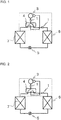
- Fig. 1 is a refrigerant circuit diagram for illustrating an air-conditioning apparatus during a heating operation according to Embodiment 1 of the present invention.
- a four-way valve 4 is switched to the heating operation (see the solid line of Fig. 1 ).
- a compressor 3 the four-way valve 4, an indoor heat exchanger 6, an expansion valve 5, an outdoor heat exchanger 7, and the four-way valve 4 are annularly connected through refrigerant pipes.
- Mufflers 1 are mufflers for an air-conditioning apparatus, and are connected to a refrigerant pipe extending from a discharge port of the compressor 3 to the four-way valve 4, and connected to a refrigerant pipe extending from the four-way valve 4 to the indoor heat exchanger 6.
- the indoor heat exchanger 6 positioned on a discharge port side of the compressor 3 functions as a condenser to perform the heating operation.
- Fig. 2 is a refrigerant circuit diagram for illustrating the air-conditioning apparatus during a cooling operation according to Embodiment 1 of the present invention.
- the four-way valve 4 is switched to the cooling operation (see the solid line of Fig. 2 ).
- the compressor 3, the four-way valve 4, the outdoor heat exchanger 7, the expansion valve 5, the indoor heat exchanger 6, and the four-way valve 4 are annularly connected through the refrigerant pipes.
- the Mufflers 1 are connected to the refrigerant pipe extending from the discharge port of the compressor 3 to the four-way valve 4, and connected to the refrigerant pipe extending from the indoor heat exchanger 6 to the four-way valve 4.
- the indoor heat exchanger 6 positioned on downstream of the expansion valve 5 functions as an evaporator to perform the cooling operation.
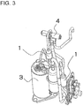
- Fig. 3 is an external view for illustrating a part of the refrigerant circuit of Fig. 1 and Fig. 2 , which is surrounded by the dotted line. Illustration is made of the mufflers 1, the compressor 3, the four-way valve 4, and the refrigerant pipes connecting those devices, which construct the air-conditioning apparatus.
- Fig. 4 is a sectional view for illustrating the muffler 1 of Fig. 1 to Fig. 3 .
- the muffler 1 is mounted to the refrigerant circuit of the air-conditioning apparatus, at least to the refrigerant pipe connected to the discharge port side of the compressor 3.
- the muffler 1 includes a muffler main body 8, an inlet pipe 9, and an outlet pipe 13.
- the muffler main body 8 is constructed of a tubular body in which an inlet small diameter portion 8a is connected through an enlarged diameter portion 8b to a large diameter portion 8c, and the large diameter portion 8c is connected through a reduced diameter portion 8d to an outlet small diameter portion 8e.
- the inlet pipe 9 is connected to the inlet small diameter portion 8a of the muffler main body 8.
- the outlet pipe 13 is connected to the outlet small diameter portion 8e of the muffler main body 8.
- the inlet pipe 9 is inserted through the inlet small diameter portion 8a of the muffler main body 8 into the muffler main body 8, and has an inserted pipe portion 10 having a length L 1 from a starting point 8bs of the enlarged diameter portion 8b of the muffler main body 8.
- a distal end of the inserted pipe portion 10 is positioned at a center of a length from an inlet to an outlet of the muffler main body 8.
- the inserted pipe portion 10 has an upper inserted pipe portion 11 and a lower inserted pipe portion 12.
- the upper inserted pipe portion 11 is a portion of a length L 2 from the starting point 8bs of the enlarged diameter portion 8b of the muffler main body 8.
- the upper inserted pipe portion 11 has an inner diameter equal to that of an upstream portion of the inlet pipe 9 with respect to the inlet small diameter portion 8a of the main body 8.
- the lower inserted pipe portion 12 is a portion of a length L 3 , which is continuous with the upper inserted pipe portion 11.
- the inner diameter of the lower inserted pipe portion 12 is set smaller than that of the upper inserted pipe portion 11.
- a ratio of an inner diameter D of the muffler main body 8 to an inner diameter D 2 of the lower inserted pipe portion 12 is set to satisfy D/D 2 >5.7.
- a length of the inserted pipe portion 10 is represented by L 1 .
- a length of the upper inserted pipe portion 11 of the inserted pipe portion 10 is represented by L 2 .
- a length of the lower inserted pipe portion 12 of the inserted pipe portion 10 is represented by L 3 .
- the relationship among those lengths is set to satisfy 1.5 ⁇ L 3 /L 2 ⁇ 3.
- the ratio of the inner diameter D of the muffler main body 8 to the inner diameter D 2 of the lower inserted pipe portion 12 is set to satisfy D/D 2 >5.7, and a ratio of the length of the lower inserted pipe portion 12 to the length of the upper inserted pipe portion 11 is set to satisfy 1.5 ⁇ L 3 /L 2 ⁇ 3.
- the pressure loss can be reduced by 66% to a maximum.
- both of this embodiment and Patent Literature 1 have the same values in the length L of the muffler main body 8, the inner diameter D of the muffler main body 8, the length L 1 of the inserted pipe portion 10, and the inner diameter D 1 of the inlet pipe 9.
- the inner diameter D of the muffler main body 8 is 28 mm to 32 mm
- the length L of the muffler main body 8 is 60 mm to 100 mm
- the length L 1 of the inserted pipe portion 10 is 30 mm to 50 mm.
- the ratio of the inner diameter D of the muffler main body 8 to the inner diameter D 2 of the lower inserted pipe portion 12 is a fixed value
- the ratio of the length L 3 of the lower inserted pipe portion 12 to the length L 2 of the upper inserted pipe portion 11, which can be manufactured satisfies 1.5 ⁇ L 3 /L 2 ⁇ 3.
- the pressure loss of the muffler in this embodiment is compared to that of the muffler having the inserted pipe portion 10 reduced in diameter from the inlet of the muffler main body 8, it is verified that the pressure loss is reduced by 33% to 66%.
- the ratio of the inner diameter D of the muffler main body 8 to the inner diameter D 2 of the lower inserted pipe portion 12 increases. Therefore, when the ratio is set to satisfy D/D 2 >5.7 as described above, the muffling effect is enhanced.
- the inner diameter of the muffler main body 8 needs to be set about 1.3 times larger than that of this embodiment.
- the muffling effect can be enhanced by reducing the inner diameter of the lower inserted pipe portion 12 without increasing the size of the muffler main body 8. Therefore, when the muffler 1 of this embodiment is employed, the muffler for an air-conditioning apparatus having an enhanced muffling effect can be introduced into an existing air-conditioning apparatus without newly designing a configuration of refrigerant circuit pipes of the air-conditioning apparatus.
- Fig. 5 to Fig. 7 are graphs for showing muffling properties of the mufflers for an air-conditioning apparatus of the above-mentioned conditions (1) to (3).
- the calculation results of the muffling property are determined with certain conditions of the length L of the muffler main body 8, the length L 1 of the inserted pipe portion 10, the length L 2 of the upper inserted pipe portion 11, the inner diameter D 1 of the upper inserted pipe portion 11, and the length L 3 of the lower inserted pipe portion 12.
- Fig. 5 is a graph for showing the muffling property of the muffler for an air-conditioning apparatus of the above-mentioned condition (1).
- the inner diameter D 1 of the upper inserted pipe portion 11 and the inner diameter D 2 of the lower inserted pipe portion 12 are equal.
- Fig. 6 is a graph for showing the muffling property of the muffler for an air-conditioning apparatus of the above-mentioned condition (2).
- the muffling effect is improved by about 8dB to a maximum (see Fig. 5 and Fig. 6 ). That is, when D/D 2 >5.7 is satisfied as in the muffler for an air-conditioning apparatus of the above-mentioned condition (2), sufficient muffling effect can be obtained as compared to the case of the above-mentioned condition (1).
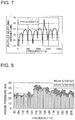
- Fig. 7 is a graph for showing the muffling property of the muffler for an air-conditioning apparatus of the above-mentioned condition (3).
- D/D 2 5.8
- Fig. 8 is a graph for showing the measurement results, with the mufflers for an air-conditioning apparatus of the above-mentioned conditions (1) and (2) each arranged on the discharge side of the compressor 3 in order to verify the efficacy of the muffling effect described above.
- a pulsation noise generated in the indoor heat exchanger due to a pressure pulsation is measured.
- a comparison is made between a measurement result of the muffler for an air-conditioning apparatus as a reference and a measurement result of the muffler for an air-conditioning apparatus in which the inner diameter D 2 of the lower inserted pipe portion 12 is reduced, it is found that the pulsation noise is reduced. From this point of view, it is found that the high muffling effect can be obtained when an inner diameter ratio is set to satisfy D/D 2 >5.7.
Landscapes
- Engineering & Computer Science (AREA)
- Mechanical Engineering (AREA)
- General Engineering & Computer Science (AREA)
- Chemical & Material Sciences (AREA)
- Combustion & Propulsion (AREA)
- Physics & Mathematics (AREA)
- Thermal Sciences (AREA)
- Compressor (AREA)
- Other Air-Conditioning Systems (AREA)
Abstract
Description
- The present invention relates to a muffler for an air-conditioning apparatus and an air-conditioning apparatus including the muffler for an air-conditioning apparatus.
- In general, a refrigerant circuit of an air-conditioning apparatus includes a compressor, a condenser, an expansion valve, and an evaporator. The air-conditioning apparatus is configured to suck, compress, and discharge refrigerant repeatedly by the compressor. Through repeated operation of the air-conditioning apparatus, the refrigerant is discharged in a pulsed manner, with the result that pressure of the refrigerant fluctuates. This phenomenon is called a pressure pulsation. There is a problem in that the pressure pulsation may be transmitted from the compressor through a discharge pipe of the compressor to an indoor-side heat exchanger, and cause resonance with the structure of the indoor-side heat exchanger, resulting in generation of noise. This noise is referred to as a pulsation noise.
- Thus, in the refrigerant circuit of the air-conditioning apparatus, a muffler is mounted to a pipe extending from a discharge port of the compressor to the indoor-side heat exchanger to reduce the pulsation noise.
- When basic characteristics of the muffler are taken into account, in order to enhance a muffling effect, a cross sectional area ratio of an expansion chamber of a muffler main body to a pipe connected to a muffler main body needs to be set large. In view of such circumstance, for example, there has been proposed a muffler employing a configuration in which an inner diameter of the muffler main body is set large so that the muffling effect is enhanced when the cross sectional area of the pipe is fixed (see, for example, Patent Literature 1).
- Further, in order to achieve downsizing of the muffler, there has been proposed a muffler downsized by changing a length and a diameter of an insertion pipe inserted into the muffler main body (see, for example, Patent Literature 2). In the muffler according to Patent Literature 2, a muffling property is enhanced by reducing an inner diameter of an inlet pipe connected to an inlet of the muffler main body before the inlet pipe enters the muffler main body, and by positioning a distal end of a portion of the inlet pipe, which is inserted into the muffler main body, at a center of the muffler main body.
-
- Patent Literature 1:
Japanese Unexamined Patent Application Publication No. Hei 9-203386 Page 3, andFig. 7 ) - Patent Literature 2:
Japanese Unexamined Patent Application Publication No. 2011-12869 Fig. 2 ) - In the muffler proposed in
Patent Literature 1, in order to enhance the muffling effect, the cross sectional area ratio of the expansion chamber of the muffler main body to the pipe connected to the muffler main body needs to be set large. Thus, there is a problem in that, when the inner diameter of the pipe connected to the muffler main body cannot be changed, the inner diameter of the muffler main body may disadvantageously increase. - In the muffler proposed in Patent Literature 2, in order to downsize the muffler while the muffling effect is maintained, an inner diameter of the inlet pipe is reduced also before the portion which is inserted into the muffler main body, and a length of an inserted pipe portion which is inserted into the muffler main body is set large to reach the vicinity of the center of the muffler main body. However, there is a problem in that a pressure loss of the refrigerant may increase.
- The present invention has been made to solve the above-mentioned problems, and an object of the present invention is to obtain a muffler for an air-conditioning apparatus, which is downsized and has an enhanced muffling effect while the pressure loss of the refrigerant is suppressed to maintain efficiency of a heat exchange, and an air-conditioning apparatus including the muffler for an air-conditioning apparatus.
- According to one embodiment of the present invention, there is provided a muffler for an air-conditioning apparatus, including: a tubular muffler main body which has small diameter portions on an inlet side and an outlet side, the small diameter portions having inner diameters smaller than an inner diameter of a central portion of the tubular muffler main body; an inlet pipe connected to the small diameter portion on the inlet side of the tubular muffler main body; and an outlet pipe connected to the small diameter portion on the outlet side of the tubular muffler main body, in which the inlet pipe is inserted into the tubular muffler main body, and has a distal end positioned at a center of a length from an inlet to an outlet of the tubular muffler main body, and in which the distal end side of the inlet pipe inserted into the tubular muffler main body has an inner diameter smaller than an inner diameter of the inlet pipe on upstream of the distal end side.
- According to the muffler for an air-conditioning apparatus of one embodiment of the present invention, the pressure loss of the refrigerant can be suppressed to be smaller than that of the related art while the muffling effect is maintained without increasing a size of the muffler main body, by positioning the distal end of the inlet pipe at the center of the length from the inlet to the outlet of the muffler main body and by setting the inner diameter of the inlet pipe on the distal end portion side smaller than the inner diameter of the inlet pipe on upstream of the distal end side.
-
- [
Fig. 1] Fig. 1 is a refrigerant circuit diagram for illustrating an air-conditioning apparatus during a heating operation according toEmbodiment 1 of the present invention. - [
Fig. 2] Fig. 2 is a refrigerant circuit diagram for illustrating the air-conditioning apparatus during a cooling operation according toEmbodiment 1 of the present invention. - [
Fig. 3] Fig. 3 is an external view for illustrating a part of the refrigerant circuit ofFig. 1 and Fig. 2 , which is surrounded by the dotted line. - [
Fig. 4] Fig. 4 is a sectional view for illustrating a muffler for the air-conditioning apparatus ofFig. 1 to Fig. 3 . - [
Fig. 5] Fig. 5 is a graph (Comparative Example 1) for showing a muffling property of the muffler for an air-conditioning apparatus when a diameter of a lower inserted pipe portion is not reduced. - [
Fig.6] Fig. 6 is a graph (Example) for showing a muffling property of the muffler for an air-conditioning apparatus when a diameter of the lower inserted pipe portion is reduced. - [
Fig. 7] Fig. 7 is a graph (Comparative Example 2) for showing a muffling property of the muffler for an air-conditioning apparatus when a diameter of the lower inserted pipe portion is reduced. - [
Fig. 8] Fig. 8 is a graph for showing measurement results (Comparative Example 1 and Example) of a pulsation noise of an air-conditioning apparatus arranged at a discharge port of a compressor for the cases of the muffler for an air-conditioning apparatus having the lower inserted pipe portion reduced in diameter and the muffler for an air-conditioning apparatus having the lower inserted pipe portion not reduced in diameter. -
Fig. 1 is a refrigerant circuit diagram for illustrating an air-conditioning apparatus during a heating operation according toEmbodiment 1 of the present invention. InFig. 1 , a four-way valve 4 is switched to the heating operation (see the solid line ofFig. 1 ). During the heating operation, acompressor 3, the four-way valve 4, anindoor heat exchanger 6, anexpansion valve 5, anoutdoor heat exchanger 7, and the four-way valve 4 are annularly connected through refrigerant pipes. Mufflers 1 are mufflers for an air-conditioning apparatus, and are connected to a refrigerant pipe extending from a discharge port of thecompressor 3 to the four-way valve 4, and connected to a refrigerant pipe extending from the four-way valve 4 to theindoor heat exchanger 6. During the heating operation, theindoor heat exchanger 6 positioned on a discharge port side of thecompressor 3 functions as a condenser to perform the heating operation. -
Fig. 2 is a refrigerant circuit diagram for illustrating the air-conditioning apparatus during a cooling operation according toEmbodiment 1 of the present invention. InFig. 2 , the four-way valve 4 is switched to the cooling operation (see the solid line ofFig. 2 ). During the cooling operation, thecompressor 3, the four-way valve 4, theoutdoor heat exchanger 7, theexpansion valve 5, theindoor heat exchanger 6, and the four-way valve 4 are annularly connected through the refrigerant pipes. The Mufflers 1 are connected to the refrigerant pipe extending from the discharge port of thecompressor 3 to the four-way valve 4, and connected to the refrigerant pipe extending from theindoor heat exchanger 6 to the four-way valve 4. During the cooling operation, theindoor heat exchanger 6 positioned on downstream of theexpansion valve 5 functions as an evaporator to perform the cooling operation. -
Fig. 3 is an external view for illustrating a part of the refrigerant circuit ofFig. 1 and Fig. 2 , which is surrounded by the dotted line. Illustration is made of themufflers 1, thecompressor 3, the four-way valve 4, and the refrigerant pipes connecting those devices, which construct the air-conditioning apparatus. -
Fig. 4 is a sectional view for illustrating themuffler 1 ofFig. 1 to Fig. 3 . As is apparent from the descriptions ofFig. 1 and Fig. 2 , themuffler 1 is mounted to the refrigerant circuit of the air-conditioning apparatus, at least to the refrigerant pipe connected to the discharge port side of thecompressor 3. Themuffler 1 includes a muffler main body 8, aninlet pipe 9, and anoutlet pipe 13. The muffler main body 8 is constructed of a tubular body in which an inletsmall diameter portion 8a is connected through an enlargeddiameter portion 8b to alarge diameter portion 8c, and thelarge diameter portion 8c is connected through a reduceddiameter portion 8d to an outletsmall diameter portion 8e. Theinlet pipe 9 is connected to the inletsmall diameter portion 8a of the muffler main body 8. Theoutlet pipe 13 is connected to the outletsmall diameter portion 8e of the muffler main body 8. - The
inlet pipe 9 is inserted through the inletsmall diameter portion 8a of the muffler main body 8 into the muffler main body 8, and has an insertedpipe portion 10 having a length L1 from a starting point 8bs of the enlargeddiameter portion 8b of the muffler main body 8. A distal end of the insertedpipe portion 10 is positioned at a center of a length from an inlet to an outlet of the muffler main body 8. The insertedpipe portion 10 has an upper insertedpipe portion 11 and a lower insertedpipe portion 12. The upper insertedpipe portion 11 is a portion of a length L2 from the starting point 8bs of the enlargeddiameter portion 8b of the muffler main body 8. The upper insertedpipe portion 11 has an inner diameter equal to that of an upstream portion of theinlet pipe 9 with respect to the inletsmall diameter portion 8a of the main body 8. The lower insertedpipe portion 12 is a portion of a length L3, which is continuous with the upper insertedpipe portion 11. The inner diameter of the lower insertedpipe portion 12 is set smaller than that of the upper insertedpipe portion 11. Thus, as theinlet pipe 9, there is employed a refrigerant pipe reduced in diameter at a portion of the lower insertedpipe portion 12. - In the
muffler 1 having the configuration described above, a ratio of an inner diameter D of the muffler main body 8 to an inner diameter D2 of the lower insertedpipe portion 12 is set to satisfy D/D2>5.7. - A length of the inserted
pipe portion 10 is represented by L1. A length of the upper insertedpipe portion 11 of the insertedpipe portion 10 is represented by L2. A length of the lower insertedpipe portion 12 of the insertedpipe portion 10 is represented by L3. The relationship among those lengths is set to satisfy 1.5<L3/L2<3. - As in the related-art muffler according to
Patent Literature 1, there is a problem in that, when a diameter of the insertedpipe portion 10 is reduced from the inlet (corresponding to the starting point 8bs of this embodiment) of the muffler main body 8 (that is, L2=0 in this embodiment), a pressure loss of the refrigerant in the refrigerant circuit may increase, with the result that a heat exchange efficiency of the air-conditioning apparatus may be lowered. However, in this embodiment, the ratio of the inner diameter D of the muffler main body 8 to the inner diameter D2 of the lower insertedpipe portion 12 is set to satisfy D/D2>5.7, and a ratio of the length of the lower insertedpipe portion 12 to the length of the upper insertedpipe portion 11 is set to satisfy 1.5<L3/L2<3. Thus, compared to the muffler in which the diameter of the insertedpipe portion 10 is reduced from the inlet of the muffler main body 8 as inPatent Literature 1, the pressure loss can be reduced by 66% to a maximum. In this comparison, both of this embodiment andPatent Literature 1 have the same values in the length L of the muffler main body 8, the inner diameter D of the muffler main body 8, the length L1 of the insertedpipe portion 10, and the inner diameter D1 of theinlet pipe 9. For example, in a general compact muffler for an air-conditioning apparatus, the inner diameter D of the muffler main body 8 is 28 mm to 32 mm, the length L of the muffler main body 8 is 60 mm to 100 mm, and the length L1 of the insertedpipe portion 10 is 30 mm to 50 mm. In the muffler having the dimensions within those ranges, when the ratio of the inner diameter D of the muffler main body 8 to the inner diameter D2 of the lower insertedpipe portion 12 is a fixed value, the ratio of the length L3 of the lower insertedpipe portion 12 to the length L2 of the upper insertedpipe portion 11, which can be manufactured, satisfies 1.5<L3/L2<3. Under such a condition, when the pressure loss of the muffler in this embodiment is compared to that of the muffler having the insertedpipe portion 10 reduced in diameter from the inlet of the muffler main body 8, it is verified that the pressure loss is reduced by 33% to 66%. In the general compact muffler for an air-conditioning apparatus, as the ratio of the inner diameter D of the muffler main body 8 to the inner diameter D2 of the lower insertedpipe portion 12 increases within a range of 5.7<D/D2, a muffling effect is enhanced. However, in that case, the pressure loss increases. Meanwhile, when the ratio of the length L3 of the lower insertedpipe portion 12 to the length L2 of the upper insertedpipe portion 11 is set to satisfy L3/L2=1.5, the pressure loss can be reduced by 66%. Therefore, even when the ratio D/D2 of the inner diameter D of the muffler main body 8 to the inner diameter D2 of the lower insertedpipe portion 12 is set to be as large as 6.7, there can be obtained a muffler having the pressure loss equivalent to that of the muffler in which the diameter of the insertedpipe portion 10 is reduced from the inlet of the muffler main body 8 while D/D2=5.7 is satisfied. - Further, regarding the muffling effect of the
mufflers 1, as the ratio of the inner diameter D of the muffler main body 8 to the inner diameter D2 of the lower insertedpipe portion 12 increases, a muffling amount increases. Therefore, when the ratio is set to satisfy D/D2>5.7 as described above, the muffling effect is enhanced. Here, when a refrigerant pipe in which a distal end side of the insertedpipe portion 10 is not reduced in diameter is employed as in the another related-art muffler (that is, L3=0 in this embodiment), it is verified that, in order to obtain the muffling effect as in this embodiment, the inner diameter of the muffler main body 8 needs to be set about 1.3 times larger than that of this embodiment. That is, in this embodiment, the muffling effect can be enhanced by reducing the inner diameter of the lower insertedpipe portion 12 without increasing the size of the muffler main body 8. Therefore, when themuffler 1 of this embodiment is employed, the muffler for an air-conditioning apparatus having an enhanced muffling effect can be introduced into an existing air-conditioning apparatus without newly designing a configuration of refrigerant circuit pipes of the air-conditioning apparatus. - Next, description is made of calculation results of the muffling effect of the muffler for an air-conditioning apparatus, which are calculated with the following conditions using an acoustic impedance.
- (1) the inner diameter D of the muffler main body=32 mm, the inner diameter of the inserted pipe portion D1=D2, D/D2=4.2
- (2) the inner diameter D of the muffler main body=32 mm, the inner diameter of the inserted pipe portion D1>D2, D/D2=5.8
- (3) the inner diameter D of the muffler main body=44.1 mm, the inner diameter of the inserted pipe portion D1=D2, D/D2=5.8
-
Fig. 5 to Fig. 7 are graphs for showing muffling properties of the mufflers for an air-conditioning apparatus of the above-mentioned conditions (1) to (3). The calculation results of the muffling property are determined with certain conditions of the length L of the muffler main body 8, the length L1 of the insertedpipe portion 10, the length L2 of the upper insertedpipe portion 11, the inner diameter D1 of the upper insertedpipe portion 11, and the length L3 of the lower insertedpipe portion 12. Specifically, the mufflers for an air-conditioning apparatus of the conditions (1) to (3) satisfy the length L of themuffler 1=92 mm, the length L1 of the insertedpipe portion 10=46 mm, and the inner diameter D1 of the upper insertedpipe portion 11 =7.6 mm. The muffler for an air-conditioning apparatus of the condition (2) satisfies the length L2 of the upper inserted pipe portion=16 mm, and the length L3 of the lower inserted pipe portion=30 mm. -
Fig. 5 is a graph for showing the muffling property of the muffler for an air-conditioning apparatus of the above-mentioned condition (1). In the muffler for an air-conditioning apparatus of the above-mentioned condition (1), the inner diameter D1 of the upper insertedpipe portion 11 and the inner diameter D2 of the lower insertedpipe portion 12 are equal. -
Fig. 6 is a graph for showing the muffling property of the muffler for an air-conditioning apparatus of the above-mentioned condition (2). The muffler for an air-conditioning apparatus of the above-mentioned condition (2) satisfies D/D2=5.8 by reducing the inner diameter D2 of the lower insertedpipe portion 12 as compared to the muffler for an air-conditioning apparatus of the above-mentioned condition (1). When the calculation results of the muffling property in the cases of the above-mentioned condition (1) and the above-mentioned condition (2) are compared, it is found that the muffling amount increases without fluctuation of a frequency having the muffling effect. In addition, it is also found that the muffling effect is improved by about 8dB to a maximum (seeFig. 5 and Fig. 6 ). That is, when D/D2>5.7 is satisfied as in the muffler for an air-conditioning apparatus of the above-mentioned condition (2), sufficient muffling effect can be obtained as compared to the case of the above-mentioned condition (1). -
Fig. 7 is a graph for showing the muffling property of the muffler for an air-conditioning apparatus of the above-mentioned condition (3). The muffler for an air-conditioning apparatus of the above-mentioned condition (3) is set to satisfy D/D2=5.8 by increasing the inner diameter D of the muffler main body 8 without changing the inner diameter D2 of the lower insertedpipe portion 12. When the calculation result of the muffling property in the case of the above-mentioned condition (3) is compared to the calculation result of the muffling property in the case of the above-mentioned condition (2), the muffling effects are substantially the same. That is, the muffling effect can be enhanced by reducing the inner diameter D2 of the lower insertedpipe portion 12 without increasing the diameter of the muffler main body 8. -
Fig. 8 is a graph for showing the measurement results, with the mufflers for an air-conditioning apparatus of the above-mentioned conditions (1) and (2) each arranged on the discharge side of thecompressor 3 in order to verify the efficacy of the muffling effect described above. A pulsation noise generated in the indoor heat exchanger due to a pressure pulsation is measured. When a comparison is made between a measurement result of the muffler for an air-conditioning apparatus as a reference and a measurement result of the muffler for an air-conditioning apparatus in which the inner diameter D2 of the lower insertedpipe portion 12 is reduced, it is found that the pulsation noise is reduced. From this point of view, it is found that the high muffling effect can be obtained when an inner diameter ratio is set to satisfy D/D2>5.7. -
- 1 muffler (for air-conditioning apparatus) 3
compressor 4 four-way valve 5expansion valve 6indoor heat exchanger 7 outdoor heat exchanger 8 mufflermain body 8a inletsmall diameter portion 8b enlarged diameter portion 8bs starting point ofenlarged diameter portion 8clarge diameter portion 8d reduceddiameter portion 8e outlet small diameter portion - 9
inlet pipe 10 insertedpipe portion 11 upper insertedpipe portion 12 lower insertedpipe portion 13 outlet pipe
Claims (5)
- A muffler for an air-conditioning apparatus, comprising:a muffler main body having a tubular shape, which has small diameter portions on an inlet side and an outlet side, the small diameter portions having inner diameters smaller than an inner diameter of a central portion of the muffler main body;an inlet pipe connected to the small diameter portion on the inlet side of the muffler main body; andan outlet pipe connected to the small diameter portion on the outlet side of the muffler main body,wherein the inlet pipe is inserted into the muffler main body, and has a distal end positioned at a center of a length from an inlet to an outlet of the muffler main body, andwherein the distal end side of the inlet pipe inserted into the muffler main body has an inner diameter smaller than an inner diameter of the inlet pipe on an upstream of the distal end side.
- A muffler for an air-conditioning apparatus, comprising:a muffler main body, having a tubular shape, in which an inlet small diameter portion is connected to a large diameter portion through an enlarged diameter portion, and the large diameter portion is connected to an outlet small diameter portion through a reduced diameter portion;an inlet pipe connected to an inlet small diameter portion of the muffler main body; andan outlet pipe connected to an outlet small diameter portion of the muffler main body,the inlet pipe having an inserted pipe portion disposed in the muffler main body, the inserted pipe portion being inserted into the muffler main body from the inlet small diameter portion and extending from a starting point of the enlarged diameter portion to an inside of the muffler main body,the inserted pipe portion having an upper inserted pipe portion positioned on an inlet side of the muffler main body and a lower inserted pipe portion positioned on an outlet side of the muffler main body,the upper inserted pipe portion having an inner diameter equal to an inner diameter of the inlet pipe on upstream of the inlet small diameter portion,the lower inserted pipe portion having a distal end positioned at a center of a length from an inlet to an outlet of the muffler main body, and having an inner diameter smaller than the inner diameter of the upper inserted pipe portion.
- The muffler for an air-conditioning apparatus of claim 2, wherein a ratio of an inner diameter D of the muffler main body to an inner diameter D2 of the lower inserted pipe portion is set to satisfy D/D2>5.7.
- The muffler for an air-conditioning apparatus of claim 2 or 3, wherein, when a length of the upper inserted pipe portion is defined as L2, and a length of the lower inserted pipe portion is defined as L3, a ratio of L2 to L3 is set to satisfy 1.5<L3/L2<3.
- An air-conditioning apparatus, comprising:a compressor, a condenser, an expansion valve, and an evaporator, connected, through refrigerant pipes, in a refrigerant circuit; anda muffler positioned at least on a discharge port side of the compressor,the muffler being the muffler for an air-conditioning apparatus of any one of claims 1 to 4.
Applications Claiming Priority (2)
| Application Number | Priority Date | Filing Date | Title |
|---|---|---|---|
| JP2014213880A JP6095628B2 (en) | 2014-10-20 | 2014-10-20 | Silencer for air conditioner and air conditioner equipped with the silencer |
| PCT/JP2015/077953 WO2016063705A1 (en) | 2014-10-20 | 2015-10-01 | Air conditioner muffler and air conditioner equipped with muffler |
Publications (2)
| Publication Number | Publication Date |
|---|---|
| EP3211352A1 true EP3211352A1 (en) | 2017-08-30 |
| EP3211352A4 EP3211352A4 (en) | 2018-06-06 |
Family
ID=55760749
Family Applications (1)
| Application Number | Title | Priority Date | Filing Date |
|---|---|---|---|
| EP15852412.4A Pending EP3211352A4 (en) | 2014-10-20 | 2015-10-01 | Air conditioner muffler and air conditioner equipped with muffler |
Country Status (5)
| Country | Link |
|---|---|
| US (1) | US10337748B2 (en) |
| EP (1) | EP3211352A4 (en) |
| JP (1) | JP6095628B2 (en) |
| CN (1) | CN106574814A (en) |
| WO (1) | WO2016063705A1 (en) |
Families Citing this family (6)
| Publication number | Priority date | Publication date | Assignee | Title |
|---|---|---|---|---|
| JP2018162690A (en) * | 2017-03-24 | 2018-10-18 | 三菱重工サーマルシステムズ株式会社 | Silencer and air conditioner |
| DE102019123902A1 (en) * | 2019-09-05 | 2021-03-11 | Hanon Systems | Device for damping pressure pulsations for a compressor of a gaseous fluid |
| CN110822693B (en) * | 2019-10-30 | 2020-11-27 | 珠海格力电器股份有限公司 | Conjoined silencer structure |
| EP4033097B1 (en) * | 2020-11-30 | 2024-04-24 | Anhui Meizhi Compressor Co., Ltd. | Suction muffler |
| KR102443707B1 (en) * | 2021-01-04 | 2022-09-15 | 엘지전자 주식회사 | Linear compressor |
| KR102523158B1 (en) * | 2021-01-06 | 2023-04-17 | 엘지전자 주식회사 | Noise reduction apparatus and air conditioner including the same |
Family Cites Families (15)
| Publication number | Priority date | Publication date | Assignee | Title |
|---|---|---|---|---|
| JPS5038511U (en) | 1973-08-06 | 1975-04-21 | ||
| US4122914A (en) * | 1976-04-30 | 1978-10-31 | Nihon Radiator Co., Ltd. | Muffler |
| JPS5921951A (en) | 1982-07-23 | 1984-02-04 | 三洋電機株式会社 | Heat pump system separation type air conditioner |
| JPH0485076U (en) * | 1990-11-30 | 1992-07-23 | ||
| JPH04292518A (en) * | 1991-03-20 | 1992-10-16 | Nissan Shatai Co Ltd | Muffling device |
| JPH09203386A (en) | 1996-01-25 | 1997-08-05 | Hitachi Ltd | Closed compressor, and refrigeration air-conditioning system using the same |
| CN1109221C (en) * | 1998-07-31 | 2003-05-21 | 海尔集团公司 | Refrigerating system of one-to-more air conditioner |
| CN2468788Y (en) * | 2001-02-27 | 2002-01-02 | 上海易初通用机器有限公司 | Noise siliencer for refrigeration medicium pipeline for automobile air-conditioning system |
| KR100774483B1 (en) * | 2006-01-05 | 2007-11-08 | 엘지전자 주식회사 | Suction muffler structure for compressor |
| JP5066344B2 (en) * | 2006-06-21 | 2012-11-07 | ハスクバーナ・ゼノア株式会社 | Scarf |
| KR101386479B1 (en) * | 2008-03-04 | 2014-04-18 | 엘지전자 주식회사 | Muffler for compressor |
| JP2011012869A (en) * | 2009-07-01 | 2011-01-20 | Panasonic Corp | Air conditioner |
| CN201935352U (en) * | 2010-12-10 | 2011-08-17 | 芜湖博耐尔汽车电气系统有限公司 | Novel silencer for refrigerant pipeline of vehicle air conditioner system |
| JP5934880B2 (en) * | 2011-09-14 | 2016-06-15 | パナソニックIpマネジメント株式会社 | Hermetic compressor |
| CN205137838U (en) * | 2014-10-20 | 2016-04-06 | 三菱电机株式会社 | Silencer and possess air conditioner of this silencer for air conditioner |
-
2014
- 2014-10-20 JP JP2014213880A patent/JP6095628B2/en active Active
-
2015
- 2015-10-01 EP EP15852412.4A patent/EP3211352A4/en active Pending
- 2015-10-01 WO PCT/JP2015/077953 patent/WO2016063705A1/en active Application Filing
- 2015-10-01 CN CN201580043791.9A patent/CN106574814A/en active Pending
- 2015-10-01 US US15/503,047 patent/US10337748B2/en active Active
Also Published As
| Publication number | Publication date |
|---|---|
| EP3211352A4 (en) | 2018-06-06 |
| WO2016063705A1 (en) | 2016-04-28 |
| US10337748B2 (en) | 2019-07-02 |
| JP2016080295A (en) | 2016-05-16 |
| JP6095628B2 (en) | 2017-03-15 |
| US20170234552A1 (en) | 2017-08-17 |
| CN106574814A (en) | 2017-04-19 |
Similar Documents
| Publication | Publication Date | Title |
|---|---|---|
| EP3211352A1 (en) | Air conditioner muffler and air conditioner equipped with muffler | |
| JP2011012869A (en) | Air conditioner | |
| CN205137838U (en) | Silencer and possess air conditioner of this silencer for air conditioner | |
| US9732741B2 (en) | Hermetic compressor comprising a suction acoustic filter | |
| CN108869303B (en) | Anti-relative punching noise reduction device and screw compressor | |
| CN112344440A (en) | Pipeline assembly of air conditioner indoor unit and air conditioner indoor unit | |
| WO2018173492A1 (en) | Muffler, and air conditioner | |
| CN116717905A (en) | Adjustable muffler and air conditioner | |
| CN103423525A (en) | Reducing pipe, refrigeration system with reducing pipe and refrigerator with refrigeration system | |
| CN103573636A (en) | Rotating compressor and exhaust pipe assembly thereof | |
| US7494328B2 (en) | NVH and gas pulsation reduction in AC compressor | |
| US11852386B2 (en) | Heat exchanger and refrigeration cycle apparatus | |
| CN208431166U (en) | A kind of muffler of compression mechanism cool equipment | |
| KR101956177B1 (en) | Muffler of air conditioning system for vehicles | |
| CN212179281U (en) | Condenser, air conditioning system, and pipe joint | |
| CN217685831U (en) | Silencer and air conditioner with same | |
| CN108317629B (en) | Air conditioner outdoor unit and air conditioner | |
| CN217685829U (en) | Silencer and air conditioner with same | |
| CN215373049U (en) | Compressor pipeline assembly, compressor and air conditioner | |
| CN109114001B (en) | Rolling rotor compressor and air conditioner | |
| CN215719345U (en) | Silencer, compressor and refrigeration equipment | |
| CN107461964A (en) | The blast pipe and air conditioner of compressor | |
| CN203375660U (en) | Air-conditioner muffler and air-conditioner with same | |
| CN117167240A (en) | Silencer and compressor | |
| CN115312016A (en) | Noise silencer |
Legal Events
| Date | Code | Title | Description |
|---|---|---|---|
| STAA | Information on the status of an ep patent application or granted ep patent |
Free format text: STATUS: THE INTERNATIONAL PUBLICATION HAS BEEN MADE |
|
| PUAI | Public reference made under article 153(3) epc to a published international application that has entered the european phase |
Free format text: ORIGINAL CODE: 0009012 |
|
| STAA | Information on the status of an ep patent application or granted ep patent |
Free format text: STATUS: REQUEST FOR EXAMINATION WAS MADE |
|
| 17P | Request for examination filed |
Effective date: 20170424 |
|
| AK | Designated contracting states |
Kind code of ref document: A1 Designated state(s): AL AT BE BG CH CY CZ DE DK EE ES FI FR GB GR HR HU IE IS IT LI LT LU LV MC MK MT NL NO PL PT RO RS SE SI SK SM TR |
|
| AX | Request for extension of the european patent |
Extension state: BA ME |
|
| DAV | Request for validation of the european patent (deleted) | ||
| DAX | Request for extension of the european patent (deleted) | ||
| A4 | Supplementary search report drawn up and despatched |
Effective date: 20180509 |
|
| RIC1 | Information provided on ipc code assigned before grant |
Ipc: F24F 1/12 20110101ALI20180503BHEP Ipc: F01N 1/02 20060101ALI20180503BHEP Ipc: F25B 41/00 20060101AFI20180503BHEP Ipc: F04B 39/00 20060101ALI20180503BHEP |
|
| TPAC | Observations by third parties |
Free format text: ORIGINAL CODE: EPIDOSNTIPA |
|
| STAA | Information on the status of an ep patent application or granted ep patent |
Free format text: STATUS: EXAMINATION IS IN PROGRESS |
|
| 17Q | First examination report despatched |
Effective date: 20200710 |
|
| STAA | Information on the status of an ep patent application or granted ep patent |
Free format text: STATUS: EXAMINATION IS IN PROGRESS |