EP3210753A1 - Mesh manufacturing method and mesh - Google Patents
Mesh manufacturing method and mesh Download PDFInfo
- Publication number
- EP3210753A1 EP3210753A1 EP15865808.8A EP15865808A EP3210753A1 EP 3210753 A1 EP3210753 A1 EP 3210753A1 EP 15865808 A EP15865808 A EP 15865808A EP 3210753 A1 EP3210753 A1 EP 3210753A1
- Authority
- EP
- European Patent Office
- Prior art keywords
- mesh
- film material
- holes
- opening
- diameter
- Prior art date
- Legal status (The legal status is an assumption and is not a legal conclusion. Google has not performed a legal analysis and makes no representation as to the accuracy of the status listed.)
- Granted
Links
Images





Classifications
-
- B—PERFORMING OPERATIONS; TRANSPORTING
- B32—LAYERED PRODUCTS
- B32B—LAYERED PRODUCTS, i.e. PRODUCTS BUILT-UP OF STRATA OF FLAT OR NON-FLAT, e.g. CELLULAR OR HONEYCOMB, FORM
- B32B3/00—Layered products comprising a layer with external or internal discontinuities or unevennesses, or a layer of non-planar shape; Layered products comprising a layer having particular features of form
- B32B3/26—Layered products comprising a layer with external or internal discontinuities or unevennesses, or a layer of non-planar shape; Layered products comprising a layer having particular features of form characterised by a particular shape of the outline of the cross-section of a continuous layer; characterised by a layer with cavities or internal voids ; characterised by an apertured layer
- B32B3/266—Layered products comprising a layer with external or internal discontinuities or unevennesses, or a layer of non-planar shape; Layered products comprising a layer having particular features of form characterised by a particular shape of the outline of the cross-section of a continuous layer; characterised by a layer with cavities or internal voids ; characterised by an apertured layer characterised by an apertured layer, the apertures going through the whole thickness of the layer, e.g. expanded metal, perforated layer, slit layer regular cells B32B3/12
-
- B—PERFORMING OPERATIONS; TRANSPORTING
- B29—WORKING OF PLASTICS; WORKING OF SUBSTANCES IN A PLASTIC STATE IN GENERAL
- B29C—SHAPING OR JOINING OF PLASTICS; SHAPING OF MATERIAL IN A PLASTIC STATE, NOT OTHERWISE PROVIDED FOR; AFTER-TREATMENT OF THE SHAPED PRODUCTS, e.g. REPAIRING
- B29C65/00—Joining or sealing of preformed parts, e.g. welding of plastics materials; Apparatus therefor
- B29C65/02—Joining or sealing of preformed parts, e.g. welding of plastics materials; Apparatus therefor by heating, with or without pressure
- B29C65/14—Joining or sealing of preformed parts, e.g. welding of plastics materials; Apparatus therefor by heating, with or without pressure using wave energy, i.e. electromagnetic radiation, or particle radiation
- B29C65/16—Laser beams
- B29C65/1629—Laser beams characterised by the way of heating the interface
- B29C65/1635—Laser beams characterised by the way of heating the interface at least passing through one of the parts to be joined, i.e. laser transmission welding
-
- B—PERFORMING OPERATIONS; TRANSPORTING
- B23—MACHINE TOOLS; METAL-WORKING NOT OTHERWISE PROVIDED FOR
- B23K—SOLDERING OR UNSOLDERING; WELDING; CLADDING OR PLATING BY SOLDERING OR WELDING; CUTTING BY APPLYING HEAT LOCALLY, e.g. FLAME CUTTING; WORKING BY LASER BEAM
- B23K26/00—Working by laser beam, e.g. welding, cutting or boring
- B23K26/36—Removing material
- B23K26/38—Removing material by boring or cutting
- B23K26/382—Removing material by boring or cutting by boring
-
- B—PERFORMING OPERATIONS; TRANSPORTING
- B29—WORKING OF PLASTICS; WORKING OF SUBSTANCES IN A PLASTIC STATE IN GENERAL
- B29C—SHAPING OR JOINING OF PLASTICS; SHAPING OF MATERIAL IN A PLASTIC STATE, NOT OTHERWISE PROVIDED FOR; AFTER-TREATMENT OF THE SHAPED PRODUCTS, e.g. REPAIRING
- B29C65/00—Joining or sealing of preformed parts, e.g. welding of plastics materials; Apparatus therefor
- B29C65/02—Joining or sealing of preformed parts, e.g. welding of plastics materials; Apparatus therefor by heating, with or without pressure
- B29C65/14—Joining or sealing of preformed parts, e.g. welding of plastics materials; Apparatus therefor by heating, with or without pressure using wave energy, i.e. electromagnetic radiation, or particle radiation
- B29C65/16—Laser beams
-
- B—PERFORMING OPERATIONS; TRANSPORTING
- B29—WORKING OF PLASTICS; WORKING OF SUBSTANCES IN A PLASTIC STATE IN GENERAL
- B29C—SHAPING OR JOINING OF PLASTICS; SHAPING OF MATERIAL IN A PLASTIC STATE, NOT OTHERWISE PROVIDED FOR; AFTER-TREATMENT OF THE SHAPED PRODUCTS, e.g. REPAIRING
- B29C65/00—Joining or sealing of preformed parts, e.g. welding of plastics materials; Apparatus therefor
- B29C65/02—Joining or sealing of preformed parts, e.g. welding of plastics materials; Apparatus therefor by heating, with or without pressure
- B29C65/14—Joining or sealing of preformed parts, e.g. welding of plastics materials; Apparatus therefor by heating, with or without pressure using wave energy, i.e. electromagnetic radiation, or particle radiation
- B29C65/16—Laser beams
- B29C65/1603—Laser beams characterised by the type of electromagnetic radiation
- B29C65/1612—Infrared [IR] radiation, e.g. by infrared lasers
- B29C65/1616—Near infrared radiation [NIR], e.g. by YAG lasers
-
- B—PERFORMING OPERATIONS; TRANSPORTING
- B29—WORKING OF PLASTICS; WORKING OF SUBSTANCES IN A PLASTIC STATE IN GENERAL
- B29C—SHAPING OR JOINING OF PLASTICS; SHAPING OF MATERIAL IN A PLASTIC STATE, NOT OTHERWISE PROVIDED FOR; AFTER-TREATMENT OF THE SHAPED PRODUCTS, e.g. REPAIRING
- B29C65/00—Joining or sealing of preformed parts, e.g. welding of plastics materials; Apparatus therefor
- B29C65/78—Means for handling the parts to be joined, e.g. for making containers or hollow articles, e.g. means for handling sheets, plates, web-like materials, tubular articles, hollow articles or elements to be joined therewith; Means for discharging the joined articles from the joining apparatus
-
- B—PERFORMING OPERATIONS; TRANSPORTING
- B29—WORKING OF PLASTICS; WORKING OF SUBSTANCES IN A PLASTIC STATE IN GENERAL
- B29C—SHAPING OR JOINING OF PLASTICS; SHAPING OF MATERIAL IN A PLASTIC STATE, NOT OTHERWISE PROVIDED FOR; AFTER-TREATMENT OF THE SHAPED PRODUCTS, e.g. REPAIRING
- B29C66/00—General aspects of processes or apparatus for joining preformed parts
- B29C66/01—General aspects dealing with the joint area or with the area to be joined
- B29C66/05—Particular design of joint configurations
- B29C66/10—Particular design of joint configurations particular design of the joint cross-sections
- B29C66/11—Joint cross-sections comprising a single joint-segment, i.e. one of the parts to be joined comprising a single joint-segment in the joint cross-section
- B29C66/112—Single lapped joints
- B29C66/1122—Single lap to lap joints, i.e. overlap joints
-
- B—PERFORMING OPERATIONS; TRANSPORTING
- B29—WORKING OF PLASTICS; WORKING OF SUBSTANCES IN A PLASTIC STATE IN GENERAL
- B29C—SHAPING OR JOINING OF PLASTICS; SHAPING OF MATERIAL IN A PLASTIC STATE, NOT OTHERWISE PROVIDED FOR; AFTER-TREATMENT OF THE SHAPED PRODUCTS, e.g. REPAIRING
- B29C66/00—General aspects of processes or apparatus for joining preformed parts
- B29C66/40—General aspects of joining substantially flat articles, e.g. plates, sheets or web-like materials; Making flat seams in tubular or hollow articles; Joining single elements to substantially flat surfaces
- B29C66/41—Joining substantially flat articles ; Making flat seams in tubular or hollow articles
- B29C66/45—Joining of substantially the whole surface of the articles
-
- B—PERFORMING OPERATIONS; TRANSPORTING
- B29—WORKING OF PLASTICS; WORKING OF SUBSTANCES IN A PLASTIC STATE IN GENERAL
- B29C—SHAPING OR JOINING OF PLASTICS; SHAPING OF MATERIAL IN A PLASTIC STATE, NOT OTHERWISE PROVIDED FOR; AFTER-TREATMENT OF THE SHAPED PRODUCTS, e.g. REPAIRING
- B29C66/00—General aspects of processes or apparatus for joining preformed parts
- B29C66/70—General aspects of processes or apparatus for joining preformed parts characterised by the composition, physical properties or the structure of the material of the parts to be joined; Joining with non-plastics material
- B29C66/71—General aspects of processes or apparatus for joining preformed parts characterised by the composition, physical properties or the structure of the material of the parts to be joined; Joining with non-plastics material characterised by the composition of the plastics material of the parts to be joined
-
- B—PERFORMING OPERATIONS; TRANSPORTING
- B29—WORKING OF PLASTICS; WORKING OF SUBSTANCES IN A PLASTIC STATE IN GENERAL
- B29C—SHAPING OR JOINING OF PLASTICS; SHAPING OF MATERIAL IN A PLASTIC STATE, NOT OTHERWISE PROVIDED FOR; AFTER-TREATMENT OF THE SHAPED PRODUCTS, e.g. REPAIRING
- B29C66/00—General aspects of processes or apparatus for joining preformed parts
- B29C66/70—General aspects of processes or apparatus for joining preformed parts characterised by the composition, physical properties or the structure of the material of the parts to be joined; Joining with non-plastics material
- B29C66/73—General aspects of processes or apparatus for joining preformed parts characterised by the composition, physical properties or the structure of the material of the parts to be joined; Joining with non-plastics material characterised by the intensive physical properties of the material of the parts to be joined, by the optical properties of the material of the parts to be joined, by the extensive physical properties of the parts to be joined, by the state of the material of the parts to be joined or by the material of the parts to be joined being a thermoplastic or a thermoset
- B29C66/733—General aspects of processes or apparatus for joining preformed parts characterised by the composition, physical properties or the structure of the material of the parts to be joined; Joining with non-plastics material characterised by the intensive physical properties of the material of the parts to be joined, by the optical properties of the material of the parts to be joined, by the extensive physical properties of the parts to be joined, by the state of the material of the parts to be joined or by the material of the parts to be joined being a thermoplastic or a thermoset characterised by the optical properties of the material of the parts to be joined, e.g. fluorescence, phosphorescence
- B29C66/7336—General aspects of processes or apparatus for joining preformed parts characterised by the composition, physical properties or the structure of the material of the parts to be joined; Joining with non-plastics material characterised by the intensive physical properties of the material of the parts to be joined, by the optical properties of the material of the parts to be joined, by the extensive physical properties of the parts to be joined, by the state of the material of the parts to be joined or by the material of the parts to be joined being a thermoplastic or a thermoset characterised by the optical properties of the material of the parts to be joined, e.g. fluorescence, phosphorescence at least one of the parts to be joined being opaque, transparent or translucent to visible light
- B29C66/73365—General aspects of processes or apparatus for joining preformed parts characterised by the composition, physical properties or the structure of the material of the parts to be joined; Joining with non-plastics material characterised by the intensive physical properties of the material of the parts to be joined, by the optical properties of the material of the parts to be joined, by the extensive physical properties of the parts to be joined, by the state of the material of the parts to be joined or by the material of the parts to be joined being a thermoplastic or a thermoset characterised by the optical properties of the material of the parts to be joined, e.g. fluorescence, phosphorescence at least one of the parts to be joined being opaque, transparent or translucent to visible light at least one of the parts to be joined being transparent or translucent to visible light
-
- B—PERFORMING OPERATIONS; TRANSPORTING
- B29—WORKING OF PLASTICS; WORKING OF SUBSTANCES IN A PLASTIC STATE IN GENERAL
- B29C—SHAPING OR JOINING OF PLASTICS; SHAPING OF MATERIAL IN A PLASTIC STATE, NOT OTHERWISE PROVIDED FOR; AFTER-TREATMENT OF THE SHAPED PRODUCTS, e.g. REPAIRING
- B29C66/00—General aspects of processes or apparatus for joining preformed parts
- B29C66/70—General aspects of processes or apparatus for joining preformed parts characterised by the composition, physical properties or the structure of the material of the parts to be joined; Joining with non-plastics material
- B29C66/73—General aspects of processes or apparatus for joining preformed parts characterised by the composition, physical properties or the structure of the material of the parts to be joined; Joining with non-plastics material characterised by the intensive physical properties of the material of the parts to be joined, by the optical properties of the material of the parts to be joined, by the extensive physical properties of the parts to be joined, by the state of the material of the parts to be joined or by the material of the parts to be joined being a thermoplastic or a thermoset
- B29C66/739—General aspects of processes or apparatus for joining preformed parts characterised by the composition, physical properties or the structure of the material of the parts to be joined; Joining with non-plastics material characterised by the intensive physical properties of the material of the parts to be joined, by the optical properties of the material of the parts to be joined, by the extensive physical properties of the parts to be joined, by the state of the material of the parts to be joined or by the material of the parts to be joined being a thermoplastic or a thermoset characterised by the material of the parts to be joined being a thermoplastic or a thermoset
- B29C66/7392—General aspects of processes or apparatus for joining preformed parts characterised by the composition, physical properties or the structure of the material of the parts to be joined; Joining with non-plastics material characterised by the intensive physical properties of the material of the parts to be joined, by the optical properties of the material of the parts to be joined, by the extensive physical properties of the parts to be joined, by the state of the material of the parts to be joined or by the material of the parts to be joined being a thermoplastic or a thermoset characterised by the material of the parts to be joined being a thermoplastic or a thermoset characterised by the material of at least one of the parts being a thermoplastic
- B29C66/73921—General aspects of processes or apparatus for joining preformed parts characterised by the composition, physical properties or the structure of the material of the parts to be joined; Joining with non-plastics material characterised by the intensive physical properties of the material of the parts to be joined, by the optical properties of the material of the parts to be joined, by the extensive physical properties of the parts to be joined, by the state of the material of the parts to be joined or by the material of the parts to be joined being a thermoplastic or a thermoset characterised by the material of the parts to be joined being a thermoplastic or a thermoset characterised by the material of at least one of the parts being a thermoplastic characterised by the materials of both parts being thermoplastics
-
- B—PERFORMING OPERATIONS; TRANSPORTING
- B29—WORKING OF PLASTICS; WORKING OF SUBSTANCES IN A PLASTIC STATE IN GENERAL
- B29C—SHAPING OR JOINING OF PLASTICS; SHAPING OF MATERIAL IN A PLASTIC STATE, NOT OTHERWISE PROVIDED FOR; AFTER-TREATMENT OF THE SHAPED PRODUCTS, e.g. REPAIRING
- B29C67/00—Shaping techniques not covered by groups B29C39/00 - B29C65/00, B29C70/00 or B29C73/00
-
- B—PERFORMING OPERATIONS; TRANSPORTING
- B29—WORKING OF PLASTICS; WORKING OF SUBSTANCES IN A PLASTIC STATE IN GENERAL
- B29D—PRODUCING PARTICULAR ARTICLES FROM PLASTICS OR FROM SUBSTANCES IN A PLASTIC STATE
- B29D28/00—Producing nets or the like, e.g. meshes, lattices
-
- B—PERFORMING OPERATIONS; TRANSPORTING
- B32—LAYERED PRODUCTS
- B32B—LAYERED PRODUCTS, i.e. PRODUCTS BUILT-UP OF STRATA OF FLAT OR NON-FLAT, e.g. CELLULAR OR HONEYCOMB, FORM
- B32B27/00—Layered products comprising a layer of synthetic resin
- B32B27/06—Layered products comprising a layer of synthetic resin as the main or only constituent of a layer, which is next to another layer of the same or of a different material
- B32B27/08—Layered products comprising a layer of synthetic resin as the main or only constituent of a layer, which is next to another layer of the same or of a different material of synthetic resin
-
- B—PERFORMING OPERATIONS; TRANSPORTING
- B32—LAYERED PRODUCTS
- B32B—LAYERED PRODUCTS, i.e. PRODUCTS BUILT-UP OF STRATA OF FLAT OR NON-FLAT, e.g. CELLULAR OR HONEYCOMB, FORM
- B32B27/00—Layered products comprising a layer of synthetic resin
- B32B27/36—Layered products comprising a layer of synthetic resin comprising polyesters
- B32B27/365—Layered products comprising a layer of synthetic resin comprising polyesters comprising polycarbonates
-
- B—PERFORMING OPERATIONS; TRANSPORTING
- B32—LAYERED PRODUCTS
- B32B—LAYERED PRODUCTS, i.e. PRODUCTS BUILT-UP OF STRATA OF FLAT OR NON-FLAT, e.g. CELLULAR OR HONEYCOMB, FORM
- B32B38/00—Ancillary operations in connection with laminating processes
- B32B38/04—Punching, slitting or perforating
-
- B—PERFORMING OPERATIONS; TRANSPORTING
- B32—LAYERED PRODUCTS
- B32B—LAYERED PRODUCTS, i.e. PRODUCTS BUILT-UP OF STRATA OF FLAT OR NON-FLAT, e.g. CELLULAR OR HONEYCOMB, FORM
- B32B38/00—Ancillary operations in connection with laminating processes
- B32B38/10—Removing layers, or parts of layers, mechanically or chemically
- B32B38/105—Removing layers, or parts of layers, mechanically or chemically on edges
-
- B—PERFORMING OPERATIONS; TRANSPORTING
- B32—LAYERED PRODUCTS
- B32B—LAYERED PRODUCTS, i.e. PRODUCTS BUILT-UP OF STRATA OF FLAT OR NON-FLAT, e.g. CELLULAR OR HONEYCOMB, FORM
- B32B7/00—Layered products characterised by the relation between layers; Layered products characterised by the relative orientation of features between layers, or by the relative values of a measurable parameter between layers, i.e. products comprising layers having different physical, chemical or physicochemical properties; Layered products characterised by the interconnection of layers
- B32B7/04—Interconnection of layers
- B32B7/05—Interconnection of layers the layers not being connected over the whole surface, e.g. discontinuous connection or patterned connection
-
- B—PERFORMING OPERATIONS; TRANSPORTING
- B23—MACHINE TOOLS; METAL-WORKING NOT OTHERWISE PROVIDED FOR
- B23K—SOLDERING OR UNSOLDERING; WELDING; CLADDING OR PLATING BY SOLDERING OR WELDING; CUTTING BY APPLYING HEAT LOCALLY, e.g. FLAME CUTTING; WORKING BY LASER BEAM
- B23K26/00—Working by laser beam, e.g. welding, cutting or boring
- B23K26/36—Removing material
- B23K26/38—Removing material by boring or cutting
-
- B—PERFORMING OPERATIONS; TRANSPORTING
- B29—WORKING OF PLASTICS; WORKING OF SUBSTANCES IN A PLASTIC STATE IN GENERAL
- B29L—INDEXING SCHEME ASSOCIATED WITH SUBCLASS B29C, RELATING TO PARTICULAR ARTICLES
- B29L2028/00—Nets or the like
-
- B—PERFORMING OPERATIONS; TRANSPORTING
- B32—LAYERED PRODUCTS
- B32B—LAYERED PRODUCTS, i.e. PRODUCTS BUILT-UP OF STRATA OF FLAT OR NON-FLAT, e.g. CELLULAR OR HONEYCOMB, FORM
- B32B38/00—Ancillary operations in connection with laminating processes
- B32B38/04—Punching, slitting or perforating
- B32B2038/047—Perforating
-
- B—PERFORMING OPERATIONS; TRANSPORTING
- B32—LAYERED PRODUCTS
- B32B—LAYERED PRODUCTS, i.e. PRODUCTS BUILT-UP OF STRATA OF FLAT OR NON-FLAT, e.g. CELLULAR OR HONEYCOMB, FORM
- B32B2250/00—Layers arrangement
- B32B2250/24—All layers being polymeric
- B32B2250/244—All polymers belonging to those covered by group B32B27/36
-
- B—PERFORMING OPERATIONS; TRANSPORTING
- B32—LAYERED PRODUCTS
- B32B—LAYERED PRODUCTS, i.e. PRODUCTS BUILT-UP OF STRATA OF FLAT OR NON-FLAT, e.g. CELLULAR OR HONEYCOMB, FORM
- B32B2307/00—Properties of the layers or laminate
- B32B2307/40—Properties of the layers or laminate having particular optical properties
- B32B2307/402—Coloured
- B32B2307/4026—Coloured within the layer by addition of a colorant, e.g. pigments, dyes
-
- B—PERFORMING OPERATIONS; TRANSPORTING
- B32—LAYERED PRODUCTS
- B32B—LAYERED PRODUCTS, i.e. PRODUCTS BUILT-UP OF STRATA OF FLAT OR NON-FLAT, e.g. CELLULAR OR HONEYCOMB, FORM
- B32B2307/00—Properties of the layers or laminate
- B32B2307/40—Properties of the layers or laminate having particular optical properties
- B32B2307/412—Transparent
-
- B—PERFORMING OPERATIONS; TRANSPORTING
- B32—LAYERED PRODUCTS
- B32B—LAYERED PRODUCTS, i.e. PRODUCTS BUILT-UP OF STRATA OF FLAT OR NON-FLAT, e.g. CELLULAR OR HONEYCOMB, FORM
- B32B2310/00—Treatment by energy or chemical effects
- B32B2310/08—Treatment by energy or chemical effects by wave energy or particle radiation
- B32B2310/0806—Treatment by energy or chemical effects by wave energy or particle radiation using electromagnetic radiation
- B32B2310/0843—Treatment by energy or chemical effects by wave energy or particle radiation using electromagnetic radiation using laser
-
- B—PERFORMING OPERATIONS; TRANSPORTING
- B32—LAYERED PRODUCTS
- B32B—LAYERED PRODUCTS, i.e. PRODUCTS BUILT-UP OF STRATA OF FLAT OR NON-FLAT, e.g. CELLULAR OR HONEYCOMB, FORM
- B32B2535/00—Medical equipment, e.g. bandage, prostheses or catheter
Definitions
- the present invention relates to a method for producing a mesh, and a mesh.
- Patent Document 1 a mesh is known in which a large number of very small through-holes are formed.
- Patent Document 1 discloses a mesh portion provided in a liquid spray apparatus.
- the mesh portion is made of resin, and has a thin plate-like outer shape in which a plurality of through-holes are formed.
- This mesh portion is provided in order to nebulize a medical fluid.
- the circumferential edge of this mesh portion is joined to a doughnut-like reinforcing portion having a hollow portion.
- the mesh portion is formed by using, for example, a mold.
- Patent Document 1 JP 2014-4208A
- the present invention was made in order to solve the above problems, and it is an object thereof to provide a method for producing a mesh, and a mesh, in which the design can be easily changed.
- the present invention is directed to a method for producing a mesh including a resin mesh main body, and a resin reinforcing member configured to reinforce the mesh main body, the method including: a step of forming a plurality of through-holes using a laser beam in a mesh formation region of a first film material made of resin; a step of forming an opening portion in a second film material made of resin; a step of layering the first film material and the second film material so that the mesh formation region and the opening portion are arranged at positions that conform to each other; and a step of joining the first film material and the second film material to each other through laser welding at a portion surrounding the opening portion.
- the through-holes of the mesh formation region are formed using an ultraviolet laser beam in this manner, and thus the design of the through-holes of the mesh formation region can be easily changed by changing the laser irradiation conditions or the like. Accordingly, a mesh having different opening diameters, numbers, or the like of through-holes can be produced at a cost lower than that in the case where a mold or the like is used. Thus, a mesh that corresponds to a medical fluid can be easily provided. Furthermore, since the first film material and the second film material are joined to each other through laser welding, the heat-affected zone can be narrowed, and thus unevenness in the spray performance of the mesh can be suppressed.
- the method for producing a mesh may further include: a step of cutting out an outer circumference of a joined portion of the first film material and the second film material.
- the method for producing a mesh may be such that a plurality of the mesh formation regions are provided in the first film material, a plurality of the opening portions are formed in the second film material, and the plurality of mesh formation regions and the plurality of opening portions are arranged at positions that conform to each other, and portions surrounding the plurality of opening portions are joined through laser welding, after which portions surrounding the plurality of joined portions are cut out.
- the method for producing a mesh may be such that, after the through-holes are formed through the first film material, the first film material and the second film material are joined to each other.
- the method for producing a mesh may further include: a step of measuring a thickness of the first film material, wherein a laser irradiation condition when forming the through-holes is set according to the thickness of the first film material.
- the present invention is directed to a method for producing a mesh including a resin mesh main body, and a resin reinforcing member configured to reinforce the mesh main body, the method including: a step of placing a second film material made of resin having an opening portion on a first film material made of resin; a step of forming a plurality of through-holes using a laser beam in a mesh formation region of the first film material; and a step of joining the first film material and the second film material to each other through laser welding at a portion surrounding the opening portion.
- the present invention is directed to a mesh including: a resin mesh main body; and a resin reinforcing member configured to reinforce the mesh main body, wherein a mesh formation region is provided in the mesh main body, and a plurality of through-holes are formed using a laser beam in the mesh formation region, the reinforcing member is formed in the shape of a ring so as to surround the mesh formation region, and the mesh main body and the reinforcing member are joined to each other through laser welding.
- the mesh may be such that each of the through-holes is formed such that an opening diameter on one end side thereof is larger than an opening diameter on another end side, and is configured such that the diameter gradually decreases from the one end side toward the other end side.
- the mesh may be such that each of the through-holes is formed such that an opening diameter on one end side thereof is larger than an opening diameter on another end side, and has a cylindrical portion, and a diameter-decreasing portion whose diameter gradually decreases from the cylindrical portion toward the other end side.
- the mesh may be such that each of the through-holes is formed such that an opening diameter on one end side thereof is larger than an opening diameter on another end side, and has a plurality of cylindrical portions having different opening diameters.
- the design can be easily changed.
- the mesh 100 is provided in, for example, a nebulizer (inhaler) in order to nebulize a medical fluid.
- a nebulizer inhaler
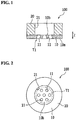
- the mesh 100 includes a mesh main body 10, and a reinforcing member 20 configured to reinforce the mesh main body 10.
- the mesh 100 is formed in a circular shape having a diameter of, for example, 6 mm.
- FIGS. 1 and 2 are schematic views illustrating the mesh 100, and the number, the dimensional relationship, and the like of through-holes 11 may be different from those in the actual state.
- the mesh main body 10 is a thin film-like member made of resin, and is formed in a circular shape in a plan view.
- the mesh main body 10 is made of, for example, transparent polycarbonate, and has a thickness of 30 ⁇ m and a diameter of 6 mm.
- the mesh main body 10 is configured to allow transmission of a laser beam for joining therethrough.
- a mesh formation region T1 is provided at the center of the mesh main body 10, and a large number of very small through-holes 11 are formed in the mesh formation region T1.
- the mesh formation region T1 is a circular region having a diameter of, for example, 2.5 mm.
- Approximately 2000 through-holes 11 are formed in the mesh formation region T1, for example, using an ultraviolet laser beam.
- each through-hole 11 is formed such that an opening diameter R1 on one of the end sides thereof is larger than an opening diameter R2 on the other end side. That is to say, the opening diameter R1 of the inlet opening on a lower face 10a side is larger than the opening diameter R2 of the outlet opening on an upper face 10b side.
- the mesh 100 is attached to a nebulizer, a medical fluid flows into the inlet openings, and a nebulized medical fluid is sprayed from the outlet openings.
- the opening diameter R1 is approximately 25 ⁇ m
- the opening diameter R2 is approximately 3 ⁇ m.
- the through-hole 11 includes a diameter-decreasing portion 111 formed on the lower face 10a side, a cylindrical portion 112 formed so as to be continuous from the diameter-decreasing portion 111, and a diameter-decreasing portion 113 formed so as to be continuous from the cylindrical portion 112.
- the diameter-decreasing portion 111 is formed such that the diameter decreases from the lower face 10a side toward the upper face 10b side.
- the diameter-decreasing portion 111 has a cross-sectional shape in which curved lines bulge inward, so that the degree of diameter decrease is smaller on the upper face 10b side than on the lower face 10a side.
- the cylindrical portion 112 has an opening diameter that is substantially the same throughout the thickness direction (the Z direction).
- the cylindrical portion 112 is disposed between the diameter-decreasing portions 111 and 113.
- the diameter-decreasing portion 113 is disposed on the upper face 10b side, and is formed such that the diameter decreases from the lower face 10a side toward the upper face 10b side.
- the diameter-decreasing portion 113 has a cross-sectional shape in which curved lines bulge inward, so that the degree of diameter decrease is smaller on the upper face 10b side than on the lower face 10a side.
- the through-hole 11 is configured such that the diameter decreases in the two diameter-decreasing portions 111 and 113 between which the cylindrical portion 112 is interposed, and thus the diameter decreases in two steps.
- the reinforcing member 20 is a film-like member made of resin, and is formed in a circular shape in a plan view as shown in FIGS. 1 and 2 .
- the reinforcing member 20 has a diameter (an outer diameter) of, for example, 6 mm.
- the reinforcing member 20 is, for example, made of black polycarbonate, and has a thickness (e.g., 410 ⁇ m) that is larger than that of the mesh main body 10.
- the reinforcing member 20 is configured to absorb a laser beam for joining.
- the reinforcing member 20 is formed in the shape of a ring inside which an opening portion 21 is disposed.
- the opening portion 21 is formed in a circular shape having an opening diameter of, for example, 2.7 mm.
- the opening portion 21 and the mesh formation region T1 are arranged at positions that conform to each other, and the mesh formation region T1 is surrounded by the ring-like reinforcing member 20.
- the mesh main body 10 and the reinforcing member 20 are joined to each other through laser welding. Specifically, in a state where the ring-like reinforcing member 20 is placed on the outer circumference of the mesh main body 10, their contact interfaces are joined to each other by welding. If the resin mesh main body 10 whose thickness is small and has low rigidity is reinforced by the reinforcing member 20 in this manner, sufficient strength of the mesh 100 is achieved as a whole.
- the first film material 50 is washed.
- the first film material 50 is made of, for example, transparent polycarbonate, and has a thickness of 30 ⁇ m. There is no particular limitation on the size of the first film material 50, but it is, for example, A5 or A6 for easy handling.
- the first film material 50 is subjected to ultrasonic washing with IPA (isopropyl alcohol) or the like for approximately several tens of seconds to several minutes. Subsequently, IPA is blown off the first film material 50 using an air gun or the like.
- IPA isopropyl alcohol
- step S2 the first film material 50 is placed on a chuck table 200 as shown in FIG. 5 .
- the first film material 50 is fixed to the chuck table 200 using a vacuum chuck.
- a porous ceramic chuck is used as the chuck table 200, so that the entire face of the first film material 50 is chucked.
- the reason for this is that, if the entire face of the first film material 50 is sucked, even when air leaks through the through-holes 11 during formation of the through-holes 11 described later, upward movement of the first film material 50 is suppressed. Accordingly, positional deviation of the first film material 50 that is to be processed is suppressed, and thus unevenness in the shape of the through-holes 11 formed is suppressed.
- the chuck table 200 is provided on an XY stage.
- the mesh formation region T1 is a circular region (e.g., having a diameter of 2.5 mm) set in advance on a face of the first film material 50.
- a plurality of such mesh formation regions T1 e.g., 320 mesh formation regions T1 are provided in the first film material 50, and are arranged in a zigzag pattern as shown in FIG. 6 .
- FIG. 6 is a schematic view, and the number, the dimensional relationship, and the like may be different from those in the actual state. This applies to the drawings that will be described later.
- Examples of the measuring apparatuses for measuring the thickness include a stylus profilometer, an optical thickness meter, and the like. The thickness may be measured using a micrometer or the like before the first film material 50 is chucked.
- the thickness of the first film material 50 is uneven between films, and is uneven in one film as well. For example, there is unevenness in the thickness by approximately 5 to 6 ⁇ m at maximum. Thus, if ultraviolet light laser irradiation conditions described later are set according to the measured thickness, unevenness in the shape (outlet opening diameter) of the through-holes 11 is suppressed.
- the number of shots set in advance as a reference is modified according to the measured thickness. That is to say, if the measured thickness is larger than the reference thickness, the number of shots is increased from the reference value, and, if the measured thickness is smaller than the reference thickness, the number of shots is decreased from the reference value.
- parameters e.g., power
- other than the number of shots may be changed.
- step S4 a large number of through-holes 11 are formed in a predetermined mesh formation region T1 using an ultraviolet laser beam.
- 2000 through-holes 11 are formed in a zigzag pattern at a spacing of 30 ⁇ m in a predetermined mesh formation region T1.
- the processing is performed in a configuration in which a YAG fourth harmonic (wavelength 266 nm, pulse width 10 to 15 ns, repetition frequency 10 kHz) is used as an ultraviolet laser beam, a single laser beam is scanned in the X direction and the Y direction using a galvano mirror, and the beam is converged using a telecentric f ⁇ lens.
- a lens having a high NA (numerical aperture) (e.g., 0.18) is used as the lens.
- the ultraviolet light laser irradiation conditions are modified according to the thickness of a predetermined mesh formation region T1.
- ultraviolet laser irradiation is performed in a defocused state, and ultraviolet laser irradiation is performed in a just focused state. That is to say, one through-hole 11 is formed by performing ultraviolet laser irradiation in two steps. Since a telecentric f ⁇ lens is used, an ultraviolet laser beam is converged perpendicular to the first film material 50 in scanning, and thus, even when the focus position is changed, ultraviolet laser irradiation can be performed at the same position.
- the XY stage on which the chuck table 200 is provided is moved in the Z direction such that the surface of the first film material 50 conforms to the just focus position.
- the XY stage is moved in the Z direction by a predetermined defocusing amount.
- the defocusing amount is, for example, 0.06 mm.
- laser irradiation in the first step is performed at a power of, for example, 50 mW. That is to say, the processing in the first step is performed in a defocused state for a number of times that corresponds to the number of holes (2000 holes) to be formed.
- the XY stage is moved in the Z direction such that the surface of the first film material 50 conforms to the just focus position.
- laser irradiation in the second step is performed at a power of, for example, 10 mW. That is to say, the processing in the second step is performed in a just focused state for a number of times that corresponds to the number of holes (2000 holes) to be formed. Accordingly, a large number of through-holes 11 having the shape as shown in FIG. 3 are formed in the mesh formation region T1.
- the opening diameter R1 of the inlet opening is approximately 25 ⁇ m
- the opening diameter R2 of the outlet opening is approximately 3 ⁇ m.
- step S5 Each time the processing has been completed for one mesh formation region T1, it is determined in step S5 whether or not the processing has been completed for all mesh formation regions T1. If the processing is not completed for all mesh formation regions T1, the procedure advances to step S6.
- step S6 the first film material 60 is moved with the XY stage in a horizontal direction, for example, by approximately 7 mm, so that a mesh formation region T1 that has not been processed is located at the processing region, after which the procedure returns to step S4. Accordingly, a large number of through-holes 11 are formed in each of the mesh formation regions T1 of the first film material 50.
- step S5 if the processing has been completed for all mesh formation regions T1 (step S5: Yes), the procedure advances to step S7, where the formed through-holes 11 are inspected.
- the opening diameter R1 of the inlet opening is measured using image processing.
- the measurement of the opening diameter R1 may be performed on all through-holes 11, or may be performed on some of the through-holes 11.
- the first film material 50 is detached from the chuck table 200, the first film material 50 is turned over and fixed to the chuck table 200. Then, the opening diameter R2 of the outlet opening is measured using image processing. The measurement of the opening diameter R2 may be performed on all through-holes 11, or may be performed on some of the through-holes 11.
- the second film material 60 is washed.
- the second film material 60 is, for example, made of black polycarbonate, and has a having a thickness of 410 ⁇ m.
- the second film material 60 is subjected to ultrasonic washing with IPA or the like for approximately several tens of seconds to several minutes. Subsequently, IPA is blown off the second film material 60 using an air gun or the like.
- step S12 the second film material 60 is placed on a chuck table 210 as shown in FIG. 11 . Then, the second film material 60 is fixed to the chuck table 210 using a vacuum chuck. It is preferable that a porous ceramic chuck is used as the chuck table 210, so that the entire face of the second film material 60 is chucked. Note that the chuck table 210 is provided on an XY stage.
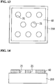
- an opening portion 21 is formed at a position that conforms to the mesh formation region T1 as shown in FIG. 12 .
- the opening portion 21 has an opening diameter of, for example, 2.7 mm, and is formed by a punch, a laser marker, or the like.
- step S14 it is determined in step S14 whether or not all opening portions 21 have been formed.
- the preset number is, for example, the same number as the number of mesh formation regions T1 of the first film material 50, that is, 320. If all opening portions 21 are not formed, the procedure advances to step S15.
- step S15 the second film material 60 is moved with the XY stage in a horizontal direction, for example, by approximately 7 mm, after which the procedure returns to step S13. Accordingly, a plurality of opening portions 21 are formed in the second film material 60 so as to respectively conform to the plurality of mesh formation regions T1 of the first film material 50.
- the XY stage for transporting the second film material 60 preferably has a driving performance similar to that of the XY stage for transporting the first film material 50. The reason for this is that positional deviation between the opening portion 21 and the through-holes 11 when the first film material 50 and the second film material 60 are layered is suppressed.
- step S14 Yes
- the procedure advances to step S16, where the formed opening portions 21 are inspected.
- the opening diameter is measured using image processing. Note that the measurement of the opening diameter may be performed on all opening portions 21, or may be performed on some of the opening portions 21. If the opening portions 21 are formed by a punch, the opening portions 21 may be inspected by checking the position of the punch (e.g., whether or not the punch has reached the bottom dead center).
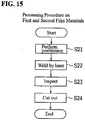
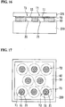
- the first film material 50 and the second film material 60 are positioned. Specifically, as shown in FIGS. 16 and 17 , the second film material 60 subjected to the above-described processing is placed on a mounting table 220. Then, the first film material 50 subjected to the above-described processing is placed on the second film material 60. At this time, the first film material 50 is positioned with respect to the second film material 60 such that the inlet openings of the through-holes 11 are on the upper side.
- the positioning is performed, for example, by forming positioning holes (not shown) at predetermined positions (e.g., for corners) of each of the first film material 50 and the second film material 60 and inserting pins through the positioning holes.
- the plate-like member 221 is configured to allow transmission of a laser beam for joining therethrough. In consideration of making the figure easier to understand, the plate-like member 221 is not shown in FIG. 17 .
- step S22 the first film material 50 and the second film material 60 are joined to each other through laser welding.
- the laser beam for joining is emitted from the plate-like member 221 side toward the second film material 60, transmitted through the plate-like member 221 and the first film material 50, and absorbed by the second film material 60.
- a ring-like region T2 (see FIG. 17 ) surrounding each opening portion 21 is joined by welding.
- the first film material 50 and the second film material 60 are welded to each other by a continuous-wave semiconductor laser at a wavelength of 808 nm.
- step S23 the joined portions are inspected using image processing or the like.
- step S24 the outer circumference of each joined portion (e.g., portion located slightly inward from the outer circumference of the ring-like region T2) is cut out by a punch or the like. Accordingly, the mesh 100 as shown in FIGS. 1 and 2 is obtained. That is to say, in this embodiment, 320 meshes 100 are formed from one first film material 50 and one second film material 60.
- the through-holes 11 of the mesh formation region T1 are formed using an ultraviolet laser beam, and thus the design of the through-holes 11 of the mesh formation region T1 can be easily changed by changing the ultraviolet light laser irradiation conditions or the like. Accordingly, the mesh 100 having different opening diameters, numbers, or the like of the through-holes 11 can be produced at a cost lower than that in the case where a mold or the like is used. Thus, the mesh 100 that corresponds to a medical fluid can be easily provided. Furthermore, since the first film material 50 and the second film material 60 are joined to each other through laser welding, the heat-affected zone can be narrowed, and thus unevenness in the spray performance of the mesh 100 can be suppressed.
- a large number of through-holes 11 are formed all at once in a plurality of mesh formation regions T1 of the first film material 50, and a plurality of opening portions 21 are formed all at once in the second film material 60, after which the first film material 50 and the second film material 60 are joined to each other through laser welding, and a plurality of meshes 100 are cut out, and thus the productivity can be improved.
- the first film material 50 and the second film material 60 are welded to each other after the through-holes 11 are formed, and thus the through-holes 11 can be formed before the first film material 50 is thermally affected as a result of welding, so that unevenness in the shape of the through-holes 11 can be suppressed.
- the ultraviolet light laser irradiation conditions are modified according to the thickness of the mesh formation region T1, and thus unevenness in the shape (outlet opening diameter) of the through-holes 11 is suppressed.
- the through-holes 11 each having the cylindrical portion 112 are formed such that the diameter decreases in two steps, and thus it is possible to suppress an increase in the spray diameter, while increasing the spray amount from the mesh 100. This aspect will be described later in detail.
- the thermal effect on the first film material 50 can be suppressed as a result of the second film material 60 absorbing the laser beam for joining, deformation or shrinkage of the mesh formation region T1 can be suppressed.
- the heat-affected zone can be narrowed by applying pressure with the plate-like member 221 during laser welding, and thus, when processing a plurality of opening portions 21 in parallel, positional deviation of the opening portions 21 due to shrinkage or the like during welding of the ring-like regions T2 surrounding the opening portions 21 can be suppressed. Accordingly, the processing can be performed in parallel, and thus the productivity is increased, and unevenness in the spray performance can be suppressed.
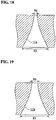
- the through-holes 11 each having the cylindrical portion 112 formed such that the diameter decreases in two steps (see FIG. 3 ), there is no limitation to this, and such a cylindrical portion may not be formed as in a through-hole 11a according to a first modified example shown in FIG. 18 .
- the through-hole 11a is formed such that an opening diameter R3 on one of the end sides thereof is larger than an opening diameter R4 on the other end side, and is configured such that the diameter gradually decreases from the one end side toward the other end side. That is to say, the through-hole 11a is formed such that the diameter continuously decreases along the entire length in the thickness direction.
- the through-hole 11a can be formed, for example, by performing processing in the first step at a power of 80 mW in a defocused state by 0.3 mm and performing processing in the second step at a power of 80 mW in a just focused state using a lens having a low numerical aperture NA (e.g., 0.025).
- NA numerical aperture
- an opening diameter R6 on the other end side becomes larger in accordance with an increase in an opening diameter R5 on the one end side as in a through-hole 11b according to a second modified example shown in FIG. 19 .
- the through-hole 11b is configured such that the diameter gradually decreases from the one end side toward the other end side, and the opening diameter is, as a whole, larger than that of the through-hole 11a.
- the opening diameter R5 of the inlet opening was about 28 ⁇ m
- the opening diameter R6 of the outlet opening was about 4.9 ⁇ m.
- Table 1 Mesh having through-holes 11a Mesh having through-holes 11b Mesh having through-holes 11 Spray amount (g) Spray diameter ( ⁇ m) Spray amount (g) Spray diameter ( ⁇ m) Spray amount (g) Spray diameter ( ⁇ m) Pulmicort 0.15 5.0 0.25 10.0 0.34 7.6 Alevaire 0.13 3.9 0.53 8.8 0.61 7.6 Mucofilin 0.06 - 0.31 8.1 0.46 6.4 Purified water 0.46 6.2 1.10 9.4 1.16 9.1
- Pulmicort registered trademark
- Alevaire registered trademark
- Mucofilin registered trademark
- purified water was sprayed individually using the mesh having the through-holes 11, and the spray amount and the spray diameter at that time were measured.
- the mesh having the through-holes 11a and the mesh having the through-holes 11b were evaluated in a similar manner. Note that, when Mucofilin was sprayed using the mesh having the through-holes 11a, the spray amount was so small that the spray diameter was not measured.
- the spray amount was larger than that of the mesh having the through-holes 11a, and the spray diameter was smaller than that of the mesh having the through-holes 11b. Accordingly, it is seen that the mesh having the through-holes 11 each formed such that the diameter decreases in two steps has a preferable spray performance because it is possible to suppress an increase in the spray diameter, while increasing the spray amount.
- the mesh having the through-holes 11 and the mesh having the through-holes 11b had similar spray diameters in the case of purified water, but significantly different spray diameters in the case of medical fluids (Pulmicort, Alevaire, and Mucofilin). That is to say, it will be appreciated that the mesh having the through-holes 11 has a good spray performance especially when spraying medical fluids. Note that such a difference between purified water and medical fluids seems to be derived from a difference in the viscosity or surface tension.
- a plurality of mesh main bodies each having 2800 through-holes in a zigzag pattern at a spacing of 30 ⁇ m were produced.
- the through-holes each had an opening diameter of the inlet opening of 25 ⁇ m and an opening diameter of the outlet opening of 3.5 ⁇ m.
- a plurality of reinforcing members having different thicknesses were produced.
- the reinforcing members had the same opening diameter of the opening portions of 2.3 mm.
- the mesh main bodies and the reinforcing members were joined, so that a plurality of meshes with reinforcing members having different thicknesses were produced.
- the spray amounts of the meshes were measured.
- FIG. 20 shows the results.
- the thickness of the reinforcing member is preferably 300 ⁇ m to 600 ⁇ m.
- the opening diameter of the reinforcing member is preferably 2.3 mm to 3.2 m.
- this embodiment described an example in which the mesh main body 10 and the reinforcing member 20 are joined to each other through laser welding, there is no limitation to this, and the mesh main body and the reinforcing member may be joined to each other by other methods. Furthermore, the reinforcing member may not be provided.
- the through-holes 11 each have the cylindrical portion 112 and the diameter-decreasing portion 113
- a plurality of cylindrical portions 111c and 112c having different opening diameters may be formed as in a through-hole 11c according to a third modified example shown in FIG. 22 .
- the through-hole 11c is formed such that the opening diameter on one of the end sides (inlet opening) thereof is larger than the opening diameter on the other end side (outlet opening).
- the through-hole 11c has the cylindrical portion 111c on the one end side and the cylindrical portion 112c on the other end side, and the cylindrical portions 111c and 112c are formed to be continuous via a step portion.
- the opening diameter of the cylindrical portion 111c is larger than the opening diameter of the cylindrical portion 112c, and each of the cylindrical portions 111c and 112c has an opening diameter that is substantially the same throughout the thickness direction.
- the through-hole 11c has two cylindrical portions 111c and 112c having different opening diameters, there is no limitation to this, and the through-hole may have three or more cylindrical portions having different opening diameters.
- the mesh main body 10 has a thickness of 30 ⁇ m
- the mesh main body may have a thickness other than 30 ⁇ m.
- the mesh main body may have a thickness of preferably 100 ⁇ m or less, and more preferably 50 ⁇ m or less.
- the mesh main body 10 is made of polycarbonate
- the mesh main body may be made of other materials as long as the obtained mesh main body allows through-holes to be formed therethrough and can be used for a nebulizer.
- the material of the mesh main body include polysulfone, polyphenylsulfone, polyetherimide, polyether ether ketone, polyphenylenesulfide, polyvinylidene fluoride, polyphenylene ether, polyacetal, polypropylene, polyethylene terephthalate, and the like.
- the reinforcing member 20 has a thickness of 410 ⁇ m
- the reinforcing member may have a thickness other than 410 ⁇ m.
- the reinforcing member may have a thickness of preferably 100 ⁇ m or more, and more preferably 300 ⁇ m or more.
- the reinforcing member 20 is made of polycarbonate
- the reinforcing member may be made of another material as long as the obtained reinforcing member can be joined to the mesh main body and can be used for a nebulizer.
- the material of the reinforcing member include polysulfone, polyphenylsulfone, polyetherimide, polyether ether ketone, polyphenylenesulfide, polyvinylidene fluoride, polyphenylene ether, polyacetal, polypropylene, polyethylene terephthalate, and the like.
- through-holes 11 are formed through defocusing
- through-holes having desired shapes may be formed by performing helical processing at a just focus position.
- through-holes having desired shapes may be formed by changing the mask size in the mask transfer method.
- through-holes having desired shapes may be formed by continuously changing the mask size and changing the laser beam diameter so as to change the numerical aperture NA, thereby controlling the diameter-decreasing angle of the through-holes.
- this embodiment described an example in which one through-hole 11 is formed by performing ultraviolet laser irradiation in two steps, there is no limitation to this, and a through-hole may be formed by performing laser irradiation in three steps or more.
- the ultraviolet laser beam preferably has a wavelength of 350 nm or less.
- this embodiment described an example in which the beam is converged using a telecentric f ⁇ lens, there is no limitation to this, and the beam may be converged using other lenses such as an f ⁇ lens or a spherical lens.
- this embodiment described an example in which a single laser beam is scanned, there is no limitation to this, and a laser beam may be branched using a diffractive optical element or the like and a plurality of laser beams may be scanned all at once. With this configuration, the productivity can be improved.
- this embodiment described an example in which a large number of through-holes 11 are formed in one mesh formation region T1 by performing scanning using a galvano mirror, there is no limitation to this, and a large number of through-holes may be formed in each of a plurality of mesh formation regions by performing scanning using a galvano mirror. With this configuration, the number of times that the XY stage is moved can be reduced, and thus the processing time can be shortened.
- the diameter of the mesh 100, the number, spacing, and arrangement of the through-holes 11, and the like are merely an example, and may be changed as appropriate.
- this embodiment described an example in which a semiconductor laser is used as a laser for joining the first film material 50 and the second film material 60, there is no limitation to this, and the first film material and the second film material may be joined to each other by other lasers.
- this embodiment described an example in which the ring-like region T2 surrounding each opening portion 21 is joined by welding as the laser welding region at which the first film material 50 and the second film material 60 are joined to each other, a single or a plurality of linear or dotted welding positions may be formed before the ring-like region T2 is welded.
- temporary joining can be performed at the linear or dotted welding positions, and thus the shrinkage in the laser welding of the ring-like region T2 can be further suppressed. Accordingly, the level of precision of the positions of the through-holes 11 with respect to the opening portions 21 can be improved.
- this embodiment described an example in which the first film material 50 in which the through-holes 11 are formed and the second film material 60 in which the opening portions 21 are formed are layered, there is no limitation to this, and the through-holes may be formed through the first film material in a state where the second film material in which the opening portions are formed and the first film material are layered. With this configuration, the level of precision of the positions of the through-holes with respect to the opening portions can be improved.
- this embodiment described an example in which the first film material 50 allows transmission of a laser beam for joining therethrough and the second film material 60 absorbs the laser beam for joining, there is no limitation to this, and the second film material may allow transmission of a laser beam for joining therethrough and the first film material may absorb the laser beam for joining.
- a step of, after cutting out and forming a plurality of meshes 100, washing the meshes 100 may be provided. Furthermore, a step of evaluating the spray performance of the mesh 100 may be provided.
- the present invention is applicable to a method for producing a mesh in which a plurality of through-holes are formed, and a mesh.
Landscapes
- Engineering & Computer Science (AREA)
- Mechanical Engineering (AREA)
- Physics & Mathematics (AREA)
- Optics & Photonics (AREA)
- Health & Medical Sciences (AREA)
- Toxicology (AREA)
- Electromagnetism (AREA)
- Plasma & Fusion (AREA)
- Laser Beam Processing (AREA)
- Lining Or Joining Of Plastics Or The Like (AREA)
- Laminated Bodies (AREA)
Abstract
Description
- The present invention relates to a method for producing a mesh, and a mesh.
- Conventionally, a mesh is known in which a large number of very small through-holes are formed (see
Patent Document 1, for example). -
Patent Document 1 discloses a mesh portion provided in a liquid spray apparatus. The mesh portion is made of resin, and has a thin plate-like outer shape in which a plurality of through-holes are formed. This mesh portion is provided in order to nebulize a medical fluid. The circumferential edge of this mesh portion is joined to a doughnut-like reinforcing portion having a hollow portion. Thus, the resin mesh portion whose thickness is small and has low rigidity is reinforced by the reinforcing portion, and thus sufficient strength is achieved as a whole. The mesh portion is formed by using, for example, a mold. - Patent Document 1:
JP 2014-4208A - However, in the case where a mesh portion is formed by using a mold as described above, it is necessary to change the mold that is to be used, in order to change the opening diameter, the number, or the like of through-holes. That is to say, it is difficult to change the design of the mesh portion.
- The present invention was made in order to solve the above problems, and it is an object thereof to provide a method for producing a mesh, and a mesh, in which the design can be easily changed.
- The present invention is directed to a method for producing a mesh including a resin mesh main body, and a resin reinforcing member configured to reinforce the mesh main body, the method including: a step of forming a plurality of through-holes using a laser beam in a mesh formation region of a first film material made of resin; a step of forming an opening portion in a second film material made of resin; a step of layering the first film material and the second film material so that the mesh formation region and the opening portion are arranged at positions that conform to each other; and a step of joining the first film material and the second film material to each other through laser welding at a portion surrounding the opening portion.
- The through-holes of the mesh formation region are formed using an ultraviolet laser beam in this manner, and thus the design of the through-holes of the mesh formation region can be easily changed by changing the laser irradiation conditions or the like. Accordingly, a mesh having different opening diameters, numbers, or the like of through-holes can be produced at a cost lower than that in the case where a mold or the like is used. Thus, a mesh that corresponds to a medical fluid can be easily provided. Furthermore, since the first film material and the second film material are joined to each other through laser welding, the heat-affected zone can be narrowed, and thus unevenness in the spray performance of the mesh can be suppressed.
- The method for producing a mesh may further include: a step of cutting out an outer circumference of a joined portion of the first film material and the second film material.
- In this case, the method for producing a mesh may be such that a plurality of the mesh formation regions are provided in the first film material, a plurality of the opening portions are formed in the second film material, and the plurality of mesh formation regions and the plurality of opening portions are arranged at positions that conform to each other, and portions surrounding the plurality of opening portions are joined through laser welding, after which portions surrounding the plurality of joined portions are cut out.
- The method for producing a mesh may be such that, after the through-holes are formed through the first film material, the first film material and the second film material are joined to each other.
- The method for producing a mesh may further include: a step of measuring a thickness of the first film material, wherein a laser irradiation condition when forming the through-holes is set according to the thickness of the first film material.
- Furthermore, the present invention is directed to a method for producing a mesh including a resin mesh main body, and a resin reinforcing member configured to reinforce the mesh main body, the method including: a step of placing a second film material made of resin having an opening portion on a first film material made of resin; a step of forming a plurality of through-holes using a laser beam in a mesh formation region of the first film material; and a step of joining the first film material and the second film material to each other through laser welding at a portion surrounding the opening portion.
- Furthermore, the present invention is directed to a mesh including: a resin mesh main body; and a resin reinforcing member configured to reinforce the mesh main body, wherein a mesh formation region is provided in the mesh main body, and a plurality of through-holes are formed using a laser beam in the mesh formation region, the reinforcing member is formed in the shape of a ring so as to surround the mesh formation region, and the mesh main body and the reinforcing member are joined to each other through laser welding.
- The mesh may be such that each of the through-holes is formed such that an opening diameter on one end side thereof is larger than an opening diameter on another end side, and is configured such that the diameter gradually decreases from the one end side toward the other end side.
- The mesh may be such that each of the through-holes is formed such that an opening diameter on one end side thereof is larger than an opening diameter on another end side, and has a cylindrical portion, and a diameter-decreasing portion whose diameter gradually decreases from the cylindrical portion toward the other end side.
- The mesh may be such that each of the through-holes is formed such that an opening diameter on one end side thereof is larger than an opening diameter on another end side, and has a plurality of cylindrical portions having different opening diameters.
- According to the method for producing a mesh, and the mesh of the present invention, the design can be easily changed.
-
- FIG. 1
- is a cross-sectional view schematically showing a mesh according to an embodiment of the present invention.
- FIG. 2
- is a plan view schematically showing the mesh in
FIG. 1 . - FIG. 3
- is an enlarged cross-sectional view showing a through-hole of the mesh in
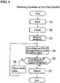
FIG. 1 . - FIG. 4
- is a flowchart illustrating the processing procedure on a first film material, in the method for producing a mesh of this embodiment.
- FIG. 5
- is a cross-sectional view schematically showing a state in which the first film material is chucked.
- FIG. 6
- is a plan view schematically showing a state in which the first film material is chucked.
- FIG. 7
- is a plan view schematically showing a state in which through-holes are formed in one mesh formation region of the first film material.
- FIG. 8
- is a plan view schematically showing a state in which through-holes are formed in all mesh formation regions of the first film material.
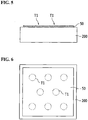
- FIG. 9
- is a cross-sectional view schematically showing a state in which through-holes are formed in all mesh formation regions of the first film material.
- FIG. 10
- is a flowchart illustrating the processing procedure on a second film material, in the method for producing a mesh of this embodiment.
- FIG. 11
- is a cross-sectional view schematically showing a state in which the second film material is chucked.
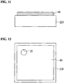
- FIG. 12
- is a plan view schematically showing a state in which one opening portion is formed in the second film material.
- FIG. 13
- is a plan view schematically showing a state in which all opening portions are formed in the second film material.
- FIG. 14
- is a cross-sectional view schematically showing a state in which all opening portions are formed in the second film material.
- FIG. 15
- is a flowchart illustrating the processing procedure on both a first film material and a second film material, in the method for producing a mesh of this embodiment.
- FIG. 16
- is a cross-sectional view schematically showing a state in which the first film material and the second film material are positioned.
- FIG. 17
- is a plan view schematically showing a state in which the first film material and the second film material are positioned.
- FIG. 18
- is an enlarged cross-sectional view showing a through-hole according to a first modified example of this embodiment.
- FIG. 19
- is an enlarged cross-sectional view showing a through-hole according to a second modified example of this embodiment.
- FIG. 20
- is a graph showing a relationship between the thickness of the reinforcing member and the spray amount.
- FIG. 21
- is a graph showing a relationship between the opening diameter of each opening portion of the reinforcing member and the spray amount.
- FIG. 22
- is an enlarged cross-sectional view showing a through-hole according to a third modified example of this embodiment.
- Hereinafter, an embodiment of the present invention will be described with reference to the drawings.
- First, the structure of a
mesh 100 according to an embodiment of the present invention will be described with reference toFIGS. 1 to 3 . Themesh 100 is provided in, for example, a nebulizer (inhaler) in order to nebulize a medical fluid. - As shown in
FIGS. 1 and 2 , themesh 100 includes a meshmain body 10, and a reinforcingmember 20 configured to reinforce the meshmain body 10. In a plan view, themesh 100 is formed in a circular shape having a diameter of, for example, 6 mm. Note thatFIGS. 1 and 2 are schematic views illustrating themesh 100, and the number, the dimensional relationship, and the like of through-holes 11 may be different from those in the actual state. - The mesh
main body 10 is a thin film-like member made of resin, and is formed in a circular shape in a plan view. The meshmain body 10 is made of, for example, transparent polycarbonate, and has a thickness of 30 µm and a diameter of 6 mm. Thus, the meshmain body 10 is configured to allow transmission of a laser beam for joining therethrough. - Furthermore, a mesh formation region T1 is provided at the center of the mesh
main body 10, and a large number of very small through-holes 11 are formed in the mesh formation region T1. In a plan view, the mesh formation region T1 is a circular region having a diameter of, for example, 2.5 mm. Approximately 2000 through-holes 11 are formed in the mesh formation region T1, for example, using an ultraviolet laser beam. - As shown in
FIG. 3 , each through-hole 11 is formed such that an opening diameter R1 on one of the end sides thereof is larger than an opening diameter R2 on the other end side. That is to say, the opening diameter R1 of the inlet opening on alower face 10a side is larger than the opening diameter R2 of the outlet opening on anupper face 10b side. If themesh 100 is attached to a nebulizer, a medical fluid flows into the inlet openings, and a nebulized medical fluid is sprayed from the outlet openings. For example, the opening diameter R1 is approximately 25 µm, and the opening diameter R2 is approximately 3 µm. - Furthermore, the through-
hole 11 includes a diameter-decreasingportion 111 formed on thelower face 10a side, acylindrical portion 112 formed so as to be continuous from the diameter-decreasingportion 111, and a diameter-decreasingportion 113 formed so as to be continuous from thecylindrical portion 112. - The diameter-decreasing
portion 111 is formed such that the diameter decreases from thelower face 10a side toward theupper face 10b side. The diameter-decreasingportion 111 has a cross-sectional shape in which curved lines bulge inward, so that the degree of diameter decrease is smaller on theupper face 10b side than on thelower face 10a side. - The
cylindrical portion 112 has an opening diameter that is substantially the same throughout the thickness direction (the Z direction). Thecylindrical portion 112 is disposed between the diameter-decreasingportions - The diameter-decreasing
portion 113 is disposed on theupper face 10b side, and is formed such that the diameter decreases from thelower face 10a side toward theupper face 10b side. The diameter-decreasingportion 113 has a cross-sectional shape in which curved lines bulge inward, so that the degree of diameter decrease is smaller on theupper face 10b side than on thelower face 10a side. - Accordingly, the through-
hole 11 is configured such that the diameter decreases in the two diameter-decreasingportions cylindrical portion 112 is interposed, and thus the diameter decreases in two steps. - The reinforcing
member 20 is a film-like member made of resin, and is formed in a circular shape in a plan view as shown inFIGS. 1 and 2 . The reinforcingmember 20 has a diameter (an outer diameter) of, for example, 6 mm. The reinforcingmember 20 is, for example, made of black polycarbonate, and has a thickness (e.g., 410 µm) that is larger than that of the meshmain body 10. The reinforcingmember 20 is configured to absorb a laser beam for joining. - Furthermore, the reinforcing
member 20 is formed in the shape of a ring inside which anopening portion 21 is disposed. In a plan view, the openingportion 21 is formed in a circular shape having an opening diameter of, for example, 2.7 mm. The openingportion 21 and the mesh formation region T1 are arranged at positions that conform to each other, and the mesh formation region T1 is surrounded by the ring-like reinforcingmember 20. Thus, when a medical fluid is sprayed from the through-holes 11 of the mesh formation region T1, the medical fluid passes through the openingportion 21 of the reinforcingmember 20. - The mesh
main body 10 and the reinforcingmember 20 are joined to each other through laser welding. Specifically, in a state where the ring-like reinforcingmember 20 is placed on the outer circumference of the meshmain body 10, their contact interfaces are joined to each other by welding. If the resin meshmain body 10 whose thickness is small and has low rigidity is reinforced by the reinforcingmember 20 in this manner, sufficient strength of themesh 100 is achieved as a whole. - Next, a method for producing the
mesh 100 according to this embodiment will be described with reference toFIGS. 1 to 17 . Below, the processing procedure on each of afirst film material 50 and asecond film material 60 will be described, after which the processing procedure on both thefirst film material 50 and thesecond film material 60 will be described. - First, in step S1 of
FIG. 4 , thefirst film material 50 is washed. Thefirst film material 50 is made of, for example, transparent polycarbonate, and has a thickness of 30 µm. There is no particular limitation on the size of thefirst film material 50, but it is, for example, A5 or A6 for easy handling. In this washing step, thefirst film material 50 is subjected to ultrasonic washing with IPA (isopropyl alcohol) or the like for approximately several tens of seconds to several minutes. Subsequently, IPA is blown off thefirst film material 50 using an air gun or the like. - Next, in step S2, the
first film material 50 is placed on a chuck table 200 as shown inFIG. 5 . Then, thefirst film material 50 is fixed to the chuck table 200 using a vacuum chuck. It is preferable that a porous ceramic chuck is used as the chuck table 200, so that the entire face of thefirst film material 50 is chucked. The reason for this is that, if the entire face of thefirst film material 50 is sucked, even when air leaks through the through-holes 11 during formation of the through-holes 11 described later, upward movement of thefirst film material 50 is suppressed. Accordingly, positional deviation of thefirst film material 50 that is to be processed is suppressed, and thus unevenness in the shape of the through-holes 11 formed is suppressed. Note that the chuck table 200 is provided on an XY stage. - Next, in step S3, the thickness of the mesh formation region T1 of the
first film material 50 is measured. The mesh formation region T1 is a circular region (e.g., having a diameter of 2.5 mm) set in advance on a face of thefirst film material 50. Specifically, a plurality of such mesh formation regions T1 (e.g., 320 mesh formation regions T1) are provided in thefirst film material 50, and are arranged in a zigzag pattern as shown inFIG. 6 . Note thatFIG. 6 is a schematic view, and the number, the dimensional relationship, and the like may be different from those in the actual state. This applies to the drawings that will be described later. Examples of the measuring apparatuses for measuring the thickness include a stylus profilometer, an optical thickness meter, and the like. The thickness may be measured using a micrometer or the like before thefirst film material 50 is chucked. - The thickness of the
first film material 50 is uneven between films, and is uneven in one film as well. For example, there is unevenness in the thickness by approximately 5 to 6 µm at maximum. Thus, if ultraviolet light laser irradiation conditions described later are set according to the measured thickness, unevenness in the shape (outlet opening diameter) of the through-holes 11 is suppressed. - As to a specific example, the number of shots set in advance as a reference is modified according to the measured thickness. That is to say, if the measured thickness is larger than the reference thickness, the number of shots is increased from the reference value, and, if the measured thickness is smaller than the reference thickness, the number of shots is decreased from the reference value. Note that parameters (e.g., power) other than the number of shots may be changed.
- Next, in step S4, a large number of through-
holes 11 are formed in a predetermined mesh formation region T1 using an ultraviolet laser beam. For example, 2000 through-holes 11 are formed in a zigzag pattern at a spacing of 30 µm in a predetermined mesh formation region T1. - In this embodiment, the processing is performed in a configuration in which a YAG fourth harmonic (wavelength 266 nm,
pulse width 10 to 15 ns,repetition frequency 10 kHz) is used as an ultraviolet laser beam, a single laser beam is scanned in the X direction and the Y direction using a galvano mirror, and the beam is converged using a telecentric fθ lens. A lens having a high NA (numerical aperture) (e.g., 0.18) is used as the lens. Furthermore, as described above, the ultraviolet light laser irradiation conditions are modified according to the thickness of a predetermined mesh formation region T1. - In this embodiment, in order to form a through-
hole 11, ultraviolet laser irradiation is performed in a defocused state, and ultraviolet laser irradiation is performed in a just focused state. That is to say, one through-hole 11 is formed by performing ultraviolet laser irradiation in two steps. Since a telecentric fθ lens is used, an ultraviolet laser beam is converged perpendicular to thefirst film material 50 in scanning, and thus, even when the focus position is changed, ultraviolet laser irradiation can be performed at the same position. - Specifically, first, the XY stage on which the chuck table 200 is provided is moved in the Z direction such that the surface of the
first film material 50 conforms to the just focus position. Subsequently, the XY stage is moved in the Z direction by a predetermined defocusing amount. The defocusing amount is, for example, 0.06 mm. Then, laser irradiation in the first step is performed at a power of, for example, 50 mW. That is to say, the processing in the first step is performed in a defocused state for a number of times that corresponds to the number of holes (2000 holes) to be formed. - Subsequently, the XY stage is moved in the Z direction such that the surface of the
first film material 50 conforms to the just focus position. Then, laser irradiation in the second step is performed at a power of, for example, 10 mW. That is to say, the processing in the second step is performed in a just focused state for a number of times that corresponds to the number of holes (2000 holes) to be formed. Accordingly, a large number of through-holes 11 having the shape as shown inFIG. 3 are formed in the mesh formation region T1. Note that the opening diameter R1 of the inlet opening is approximately 25 µm, and the opening diameter R2 of the outlet opening is approximately 3 µm. - In this manner, a large number of through-
holes 11 are formed in one mesh formation region T1 as shown inFIG. 7 . Each time the processing has been completed for one mesh formation region T1, it is determined in step S5 whether or not the processing has been completed for all mesh formation regions T1. If the processing is not completed for all mesh formation regions T1, the procedure advances to step S6. - In step S6, the
first film material 60 is moved with the XY stage in a horizontal direction, for example, by approximately 7 mm, so that a mesh formation region T1 that has not been processed is located at the processing region, after which the procedure returns to step S4. Accordingly, a large number of through-holes 11 are formed in each of the mesh formation regions T1 of thefirst film material 50. - As shown in
FIGS. 8 and9 , if the processing has been completed for all mesh formation regions T1 (step S5: Yes), the procedure advances to step S7, where the formed through-holes 11 are inspected. - In the inspection of a through-
hole 11, first, the opening diameter R1 of the inlet opening is measured using image processing. The measurement of the opening diameter R1 may be performed on all through-holes 11, or may be performed on some of the through-holes 11. - Subsequently, the
first film material 50 is detached from the chuck table 200, thefirst film material 50 is turned over and fixed to the chuck table 200. Then, the opening diameter R2 of the outlet opening is measured using image processing. The measurement of the opening diameter R2 may be performed on all through-holes 11, or may be performed on some of the through-holes 11. - In this manner, the processing on the
first film material 50 is performed. - First, in step S11 of
FIG. 10 , thesecond film material 60 is washed. Thesecond film material 60 is, for example, made of black polycarbonate, and has a having a thickness of 410 µm. There is no particular limitation on the size of thesecond film material 60, but it is, for example, the same as the size (A5 or A6) of thefirst film material 50. In this washing step, thesecond film material 60 is subjected to ultrasonic washing with IPA or the like for approximately several tens of seconds to several minutes. Subsequently, IPA is blown off thesecond film material 60 using an air gun or the like. - Next, in step S12, the
second film material 60 is placed on a chuck table 210 as shown inFIG. 11 . Then, thesecond film material 60 is fixed to the chuck table 210 using a vacuum chuck. It is preferable that a porous ceramic chuck is used as the chuck table 210, so that the entire face of thesecond film material 60 is chucked. Note that the chuck table 210 is provided on an XY stage. - Next, in step S13, an opening
portion 21 is formed at a position that conforms to the mesh formation region T1 as shown inFIG. 12 . The openingportion 21 has an opening diameter of, for example, 2.7 mm, and is formed by a punch, a laser marker, or the like. - Subsequently, when one
opening portion 21 is formed, it is determined in step S14 whether or not all openingportions 21 have been formed. Note that all openingportions 21 make up a preset number of opening portions. The preset number is, for example, the same number as the number of mesh formation regions T1 of thefirst film material 50, that is, 320. If all openingportions 21 are not formed, the procedure advances to step S15. - In step S15, the
second film material 60 is moved with the XY stage in a horizontal direction, for example, by approximately 7 mm, after which the procedure returns to step S13. Accordingly, a plurality of openingportions 21 are formed in thesecond film material 60 so as to respectively conform to the plurality of mesh formation regions T1 of thefirst film material 50. The XY stage for transporting thesecond film material 60 preferably has a driving performance similar to that of the XY stage for transporting thefirst film material 50. The reason for this is that positional deviation between the openingportion 21 and the through-holes 11 when thefirst film material 50 and thesecond film material 60 are layered is suppressed. - Then, if all opening
portions 21 are formed as shown inFIGS. 13 and 14 (step S14: Yes), the procedure advances to step S16, where the formed openingportions 21 are inspected. - In the inspection of an
opening portion 21, for example, the opening diameter is measured using image processing. Note that the measurement of the opening diameter may be performed on all openingportions 21, or may be performed on some of the openingportions 21. If the openingportions 21 are formed by a punch, the openingportions 21 may be inspected by checking the position of the punch (e.g., whether or not the punch has reached the bottom dead center). - In this manner, the processing on the
second film material 60 is performed. - First, in step S21 of
FIG. 15 , thefirst film material 50 and thesecond film material 60 are positioned. Specifically, as shown inFIGS. 16 and 17 , thesecond film material 60 subjected to the above-described processing is placed on a mounting table 220. Then, thefirst film material 50 subjected to the above-described processing is placed on thesecond film material 60. At this time, thefirst film material 50 is positioned with respect to thesecond film material 60 such that the inlet openings of the through-holes 11 are on the upper side. The positioning is performed, for example, by forming positioning holes (not shown) at predetermined positions (e.g., for corners) of each of thefirst film material 50 and thesecond film material 60 and inserting pins through the positioning holes. - Subsequently, the
first film material 50 and thesecond film material 60 are pressurized using a plate-like member 221 (seeFIG. 16 ). The plate-like member 221 is configured to allow transmission of a laser beam for joining therethrough. In consideration of making the figure easier to understand, the plate-like member 221 is not shown inFIG. 17 . - In step S22, the
first film material 50 and thesecond film material 60 are joined to each other through laser welding. The laser beam for joining is emitted from the plate-like member 221 side toward thesecond film material 60, transmitted through the plate-like member 221 and thefirst film material 50, and absorbed by thesecond film material 60. Specifically, a ring-like region T2 (seeFIG. 17 ) surrounding each openingportion 21 is joined by welding. In this embodiment, thefirst film material 50 and thesecond film material 60 are welded to each other by a continuous-wave semiconductor laser at a wavelength of 808 nm. - Then, in step S23, the joined portions are inspected using image processing or the like. Subsequently, in step S24, the outer circumference of each joined portion (e.g., portion located slightly inward from the outer circumference of the ring-like region T2) is cut out by a punch or the like. Accordingly, the
mesh 100 as shown inFIGS. 1 and 2 is obtained. That is to say, in this embodiment, 320 meshes 100 are formed from onefirst film material 50 and onesecond film material 60. - In this embodiment, as described above, the through-
holes 11 of the mesh formation region T1 are formed using an ultraviolet laser beam, and thus the design of the through-holes 11 of the mesh formation region T1 can be easily changed by changing the ultraviolet light laser irradiation conditions or the like. Accordingly, themesh 100 having different opening diameters, numbers, or the like of the through-holes 11 can be produced at a cost lower than that in the case where a mold or the like is used. Thus, themesh 100 that corresponds to a medical fluid can be easily provided. Furthermore, since thefirst film material 50 and thesecond film material 60 are joined to each other through laser welding, the heat-affected zone can be narrowed, and thus unevenness in the spray performance of themesh 100 can be suppressed. - Furthermore, in this embodiment, a large number of through-
holes 11 are formed all at once in a plurality of mesh formation regions T1 of thefirst film material 50, and a plurality of openingportions 21 are formed all at once in thesecond film material 60, after which thefirst film material 50 and thesecond film material 60 are joined to each other through laser welding, and a plurality ofmeshes 100 are cut out, and thus the productivity can be improved. - Furthermore, in this embodiment, the
first film material 50 and thesecond film material 60 are welded to each other after the through-holes 11 are formed, and thus the through-holes 11 can be formed before thefirst film material 50 is thermally affected as a result of welding, so that unevenness in the shape of the through-holes 11 can be suppressed. - Furthermore, in this embodiment, the ultraviolet light laser irradiation conditions are modified according to the thickness of the mesh formation region T1, and thus unevenness in the shape (outlet opening diameter) of the through-
holes 11 is suppressed. - Furthermore, in this embodiment, the through-
holes 11 each having thecylindrical portion 112 are formed such that the diameter decreases in two steps, and thus it is possible to suppress an increase in the spray diameter, while increasing the spray amount from themesh 100. This aspect will be described later in detail. - Furthermore, in this embodiment, since the thermal effect on the
first film material 50 can be suppressed as a result of thesecond film material 60 absorbing the laser beam for joining, deformation or shrinkage of the mesh formation region T1 can be suppressed. - Furthermore, in this embodiment, the heat-affected zone can be narrowed by applying pressure with the plate-
like member 221 during laser welding, and thus, when processing a plurality of openingportions 21 in parallel, positional deviation of the openingportions 21 due to shrinkage or the like during welding of the ring-like regions T2 surrounding the openingportions 21 can be suppressed. Accordingly, the processing can be performed in parallel, and thus the productivity is increased, and unevenness in the spray performance can be suppressed. - Although this embodiment described the through-
holes 11 each having thecylindrical portion 112 formed such that the diameter decreases in two steps (seeFIG. 3 ), there is no limitation to this, and such a cylindrical portion may not be formed as in a through-hole 11a according to a first modified example shown inFIG. 18 . The through-hole 11a is formed such that an opening diameter R3 on one of the end sides thereof is larger than an opening diameter R4 on the other end side, and is configured such that the diameter gradually decreases from the one end side toward the other end side. That is to say, the through-hole 11a is formed such that the diameter continuously decreases along the entire length in the thickness direction. The through-hole 11a can be formed, for example, by performing processing in the first step at a power of 80 mW in a defocused state by 0.3 mm and performing processing in the second step at a power of 80 mW in a just focused state using a lens having a low numerical aperture NA (e.g., 0.025). - In the case where the diameter continuously decreases, an opening diameter R6 on the other end side becomes larger in accordance with an increase in an opening diameter R5 on the one end side as in a through-
hole 11b according to a second modified example shown inFIG. 19 . The through-hole 11b is configured such that the diameter gradually decreases from the one end side toward the other end side, and the opening diameter is, as a whole, larger than that of the through-hole 11a. - An evaluation test was performed on the spray performance of the meshes having the through-
holes 11 to 11b. Table 1 shows the results. In the through-holes 11 each having thecylindrical portion 112 formed such that the diameter decreased in two steps (seeFIG. 3 ), the opening diameter R1 of the inlet opening was about 25 µm, and the opening diameter R2 of the outlet opening was about 3.3 µm. In the through-holes 11a each formed such that the diameter continuously decreased (seeFIG. 18 ), the opening diameter R3 of the inlet opening was about 25 µm, and the opening diameter R4 of the outlet opening was about 3.3 µm. In the through-holes 11b each formed such that the diameter continuously decreased (seeFIG. 19 ), the opening diameter R5 of the inlet opening was about 28 µm, and the opening diameter R6 of the outlet opening was about 4.9 µm.Table 1 Mesh having through- holes 11aMesh having through- holes 11bMesh having through- holes 11Spray amount (g) Spray diameter (µm) Spray amount (g) Spray diameter (µm) Spray amount (g) Spray diameter (µm) Pulmicort 0.15 5.0 0.25 10.0 0.34 7.6 Alevaire 0.13 3.9 0.53 8.8 0.61 7.6 Mucofilin 0.06 - 0.31 8.1 0.46 6.4 Purified water 0.46 6.2 1.10 9.4 1.16 9.1 - In this test, Pulmicort (registered trademark), Alevaire (registered trademark), Mucofilin (registered trademark), and purified water were sprayed individually using the mesh having the through-
holes 11, and the spray amount and the spray diameter at that time were measured. The mesh having the through-holes 11a and the mesh having the through-holes 11b were evaluated in a similar manner. Note that, when Mucofilin was sprayed using the mesh having the through-holes 11a, the spray amount was so small that the spray diameter was not measured. - It is seen from the test results shown in Table 1 that the mesh having the through-
holes 11b had a larger spray amount and a larger spray diameter than those of the mesh having the through-holes 11a. The reason for this seems to be that the opening diameter R6 of the outlet opening of the through-holes 11b was larger than the opening diameter R4 of the outlet opening of the through-holes 11a. That is to say, in the case where the diameter continuously decreases, an increase in the spray amount leads to an increase in the spray diameter. - In the case of the mesh having the through-
holes 11, the spray amount was larger than that of the mesh having the through-holes 11a, and the spray diameter was smaller than that of the mesh having the through-holes 11b. Accordingly, it is seen that the mesh having the through-holes 11 each formed such that the diameter decreases in two steps has a preferable spray performance because it is possible to suppress an increase in the spray diameter, while increasing the spray amount. - The mesh having the through-
holes 11 and the mesh having the through-holes 11b had similar spray diameters in the case of purified water, but significantly different spray diameters in the case of medical fluids (Pulmicort, Alevaire, and Mucofilin). That is to say, it will be appreciated that the mesh having the through-holes 11 has a good spray performance especially when spraying medical fluids. Note that such a difference between purified water and medical fluids seems to be derived from a difference in the viscosity or surface tension. - Next, a relationship between the shape of the reinforcing member and the spray amount will be described. Below, a relationship between the thickness of the reinforcing member and the spray amount will be described, after which a relationship between the opening diameter of each opening portion of the reinforcing member and the spray amount will be described.
- First, a plurality of mesh main bodies each having 2800 through-holes in a zigzag pattern at a spacing of 30 µm were produced. The through-holes each had an opening diameter of the inlet opening of 25 µm and an opening diameter of the outlet opening of 3.5 µm. Furthermore, a plurality of reinforcing members having different thicknesses were produced. The reinforcing members had the same opening diameter of the opening portions of 2.3 mm. The mesh main bodies and the reinforcing members were joined, so that a plurality of meshes with reinforcing members having different thicknesses were produced. The spray amounts of the meshes were measured.
FIG. 20 shows the results. - It is seen from
FIG. 20 that, if the thickness of the reinforcing member is as large as approximately 800 µm or is as small as approximately 200 µm, the spray amount decreases. Note that the meshes had the same total opening area of the through-holes. Accordingly, the thickness of the reinforcing member is preferably 300 µm to 600 µm. - First, a plurality of mesh main bodies similar to those described above were produced. Furthermore, a plurality of reinforcing members having different opening diameters were produced. The reinforcing members had the same thickness of 440 µm. The mesh main bodies and the reinforcing members were joined, so that a plurality of meshes having different opening diameters were produced. The spray amounts of the meshes were measured.
FIG. 21 shows the results. - It is seen from
FIG. 21 that, if the opening diameter is as large as approximately 4 mm or is as small as approximately 1.6 mm, the spray amount decreases. Note that the meshes had the same total opening area of the through-holes. Accordingly, the opening diameter of the reinforcing member is preferably 2.3 mm to 3.2 m. - The embodiment disclosed in this application is to be construed in all respects as illustrative and not limiting. The technical scope of the present invention is indicated by the appended claims rather than only by the foregoing description. All variations falling within the meaning and range of equivalency of the claims are intended to be embraced therein.
- For example, although this embodiment described an example in which the mesh
main body 10 and the reinforcingmember 20 are joined to each other through laser welding, there is no limitation to this, and the mesh main body and the reinforcing member may be joined to each other by other methods. Furthermore, the reinforcing member may not be provided. - Furthermore, although this embodiment described an example in which the through-
holes 11 each have thecylindrical portion 112 and the diameter-decreasingportion 113, there is no limitation to this, and a plurality ofcylindrical portions hole 11c according to a third modified example shown inFIG. 22 . The through-hole 11c is formed such that the opening diameter on one of the end sides (inlet opening) thereof is larger than the opening diameter on the other end side (outlet opening). Furthermore, the through-hole 11c has thecylindrical portion 111c on the one end side and thecylindrical portion 112c on the other end side, and thecylindrical portions cylindrical portion 111c is larger than the opening diameter of thecylindrical portion 112c, and each of thecylindrical portions hole 11c has twocylindrical portions - Furthermore, although this embodiment described an example in which the mesh
main body 10 has a thickness of 30 µm, there is no limitation to this, and the mesh main body may have a thickness other than 30 µm. Note that the mesh main body may have a thickness of preferably 100 µm or less, and more preferably 50 µm or less. - Furthermore, although this embodiment described an example in which the mesh
main body 10 is made of polycarbonate, there is no limitation to this, and the mesh main body may be made of other materials as long as the obtained mesh main body allows through-holes to be formed therethrough and can be used for a nebulizer. Examples of the material of the mesh main body include polysulfone, polyphenylsulfone, polyetherimide, polyether ether ketone, polyphenylenesulfide, polyvinylidene fluoride, polyphenylene ether, polyacetal, polypropylene, polyethylene terephthalate, and the like. - Furthermore, although this embodiment described an example in which the reinforcing
member 20 has a thickness of 410 µm, there is no limitation to this, and the reinforcing member may have a thickness other than 410 µm. Note that the reinforcing member may have a thickness of preferably 100 µm or more, and more preferably 300 µm or more. - Furthermore, although this embodiment described an example in which the reinforcing
member 20 is made of polycarbonate, there is no limitation to this, and the reinforcing member may be made of another material as long as the obtained reinforcing member can be joined to the mesh main body and can be used for a nebulizer. Examples of the material of the reinforcing member include polysulfone, polyphenylsulfone, polyetherimide, polyether ether ketone, polyphenylenesulfide, polyvinylidene fluoride, polyphenylene ether, polyacetal, polypropylene, polyethylene terephthalate, and the like. - Furthermore, although this embodiment described an example in which the through-
holes 11 are formed through defocusing, there is no limitation to this, and through-holes having desired shapes may be formed by performing helical processing at a just focus position. In a similar manner, through-holes having desired shapes may be formed by changing the mask size in the mask transfer method. In a similar manner, through-holes having desired shapes may be formed by continuously changing the mask size and changing the laser beam diameter so as to change the numerical aperture NA, thereby controlling the diameter-decreasing angle of the through-holes. - Furthermore, although this embodiment described an example in which one through-
hole 11 is formed by performing ultraviolet laser irradiation in two steps, there is no limitation to this, and a through-hole may be formed by performing laser irradiation in three steps or more. - Furthermore, although this embodiment described an example in which a YAG fourth harmonic was used as the ultraviolet laser beam, there is no limitation to this, and a YAG third harmonic or an excimer laser may be used as the ultraviolet laser beam. Note that the ultraviolet laser beam preferably has a wavelength of 350 nm or less.
- Furthermore, although this embodiment described an example in which the beam is converged using a telecentric fθ lens, there is no limitation to this, and the beam may be converged using other lenses such as an fθ lens or a spherical lens.
- Furthermore, although this embodiment described an example in which a single laser beam is scanned, there is no limitation to this, and a laser beam may be branched using a diffractive optical element or the like and a plurality of laser beams may be scanned all at once. With this configuration, the productivity can be improved.
- Furthermore, although this embodiment described an example in which a large number of through-
holes 11 are formed in one mesh formation region T1 by performing scanning using a galvano mirror, there is no limitation to this, and a large number of through-holes may be formed in each of a plurality of mesh formation regions by performing scanning using a galvano mirror. With this configuration, the number of times that the XY stage is moved can be reduced, and thus the processing time can be shortened. - Furthermore, although this embodiment described an example in which various types of inspections are performed, there is no limitation to this, and inspections may not be performed, or only some of the inspections may be performed.
- Furthermore, in this embodiment, the diameter of the
mesh 100, the number, spacing, and arrangement of the through-holes 11, and the like are merely an example, and may be changed as appropriate. - Furthermore, although this embodiment described an example in which a semiconductor laser is used as a laser for joining the
first film material 50 and thesecond film material 60, there is no limitation to this, and the first film material and the second film material may be joined to each other by other lasers. - Furthermore, although this embodiment described an example in which the ring-like region T2 surrounding each opening
portion 21 is joined by welding as the laser welding region at which thefirst film material 50 and thesecond film material 60 are joined to each other, a single or a plurality of linear or dotted welding positions may be formed before the ring-like region T2 is welded. With this configuration, temporary joining can be performed at the linear or dotted welding positions, and thus the shrinkage in the laser welding of the ring-like region T2 can be further suppressed. Accordingly, the level of precision of the positions of the through-holes 11 with respect to the openingportions 21 can be improved. - Furthermore, although this embodiment described an example in which the
first film material 50 in which the through-holes 11 are formed and thesecond film material 60 in which the openingportions 21 are formed are layered, there is no limitation to this, and the through-holes may be formed through the first film material in a state where the second film material in which the opening portions are formed and the first film material are layered. With this configuration, the level of precision of the positions of the through-holes with respect to the opening portions can be improved. - Furthermore, although this embodiment described an example in which the
first film material 50 allows transmission of a laser beam for joining therethrough and thesecond film material 60 absorbs the laser beam for joining, there is no limitation to this, and the second film material may allow transmission of a laser beam for joining therethrough and the first film material may absorb the laser beam for joining. - Furthermore, in this embodiment, a step of, after cutting out and forming a plurality of
meshes 100, washing themeshes 100 may be provided. Furthermore, a step of evaluating the spray performance of themesh 100 may be provided. - The present invention is applicable to a method for producing a mesh in which a plurality of through-holes are formed, and a mesh.
-
- 10
- Mesh main body
- 11
- Through-hole
- 11a
- Through-hole
- 11b
- Through-hole
- 11c
- Through-hole
- 20
- Reinforcing member
- 21
- Opening portion
- 50
- First film material
- 60
- Second film material
- 100
- Mesh
- 111c
- Cylindrical portion
- 112
- Cylindrical portion
- 112c
- Cylindrical portion
- 113
- Diameter-decreasing portion
- T1
- Mesh formation region
Claims (10)
- A method for producing a mesh including a resin mesh main body, and a resin reinforcing member configured to reinforce the mesh main body, the method comprising :a step of forming a plurality of through-holes using a laser beam in a mesh formation region of a first film material made of resin ;a step of forming an opening portion in a second film material made of resin ;a step of layering the first film material and the second film material so that the mesh formation region and the opening portion are arranged at positions that conform to each other; anda step of joining the first film material and the second film material to each other through laser welding at a portion surrounding the opening portion.
- The method for producing a mesh, according to claim 1, further comprising: a step of cutting out an outer circumference of a joined portion of the first film material and the second film material.
- The method for producing a mesh, according to claim 2,
wherein a plurality of the mesh formation regions are provided in the first film material, a plurality of the opening portions are formed in the second film material, and the plurality of mesh formation regions and the plurality of opening portions are arranged at positions that conform to each other, and
portions surrounding the plurality of opening portions are joined through laser welding, after which portions surrounding the plurality of joined portions are cut out. - The method for producing a mesh, according to any one of claims 1 to 3, wherein, after the through-holes are formed through the first film material, the first film material and the second film material are joined to each other.
- The method for producing a mesh, according to any one of claims 1 to 4, further comprising: a step of measuring a thickness of the first film material,
wherein a laser irradiation condition when forming the through-holes is set according to the thickness of the first film material. - A method for producing a mesh including a resin mesh main body, and a resin reinforcing member configured to reinforce the mesh main body, the method comprising :a step of placing a second film material made of resin having an opening portion on a first film material made of resin ;a step of forming a plurality of through-holes using a laser beam in a mesh formation region of the first film material; anda step of joining the first film material and the second film material to each other through laser welding at a portion surrounding the opening portion.
- A mesh comprising :a resin mesh main body; anda resin reinforcing member configured to reinforce the mesh main body,wherein a mesh formation region is provided in the mesh main body, and a plurality of through-holes are formed using a laser beam in the mesh formation region,the reinforcing member is formed in the shape of a ring so as to surround the mesh formation region, andthe mesh main body and the reinforcing member are joined to each other through laser welding.
- The mesh according to claim 7, wherein each of the through-holes is formed such that an opening diameter on one end side thereof is larger than an opening diameter on another end side, and is configured such that the diameter gradually decreases from the one end side toward the other end side.
- The mesh according to claim 7, wherein each of the through-holes is formed such that an opening diameter on one end side thereof is larger than an opening diameter on another end side, and has a cylindrical portion, and a diameter-decreasing portion whose diameter gradually decreases from the cylindrical portion toward the other end side.
- The mesh according to claim 7, wherein each of the through-holes is formed such that an opening diameter on one end side thereof is larger than an opening diameter on another end side, and has a plurality of cylindrical portions having different opening diameters.
Applications Claiming Priority (2)
| Application Number | Priority Date | Filing Date | Title |
|---|---|---|---|
| JP2014247338A JP6415953B2 (en) | 2014-12-05 | 2014-12-05 | Mesh manufacturing method |
| PCT/JP2015/082376 WO2016088555A1 (en) | 2014-12-05 | 2015-11-18 | Mesh manufacturing method and mesh |
Publications (3)
| Publication Number | Publication Date |
|---|---|
| EP3210753A1 true EP3210753A1 (en) | 2017-08-30 |
| EP3210753A4 EP3210753A4 (en) | 2018-03-14 |
| EP3210753B1 EP3210753B1 (en) | 2019-04-17 |
Family
ID=56091505
Family Applications (1)
| Application Number | Title | Priority Date | Filing Date |
|---|---|---|---|
| EP15865808.8A Active EP3210753B1 (en) | 2014-12-05 | 2015-11-18 | Mesh manufacturing method and mesh |
Country Status (7)
| Country | Link |
|---|---|
| US (1) | US10525658B2 (en) |
| EP (1) | EP3210753B1 (en) |
| JP (1) | JP6415953B2 (en) |
| KR (1) | KR101850259B1 (en) |
| CN (1) | CN107000327B (en) |
| BR (1) | BR112017011775B1 (en) |
| WO (1) | WO2016088555A1 (en) |
Families Citing this family (5)
| Publication number | Priority date | Publication date | Assignee | Title |
|---|---|---|---|---|
| EP3112129B1 (en) * | 2015-07-01 | 2019-12-11 | W.L. Gore & Associates GmbH | Method for the production of a vent |
| CN112763486B (en) * | 2020-11-30 | 2022-05-10 | 成都飞机工业(集团)有限责任公司 | Composite material wall plate array hole detection method based on line laser scanning |
| CN116829272B (en) * | 2021-02-05 | 2025-05-23 | 东丽株式会社 | Method for producing laminate, method for producing polymer film, and laminate |
| DE102021117021A1 (en) * | 2021-07-01 | 2023-01-05 | Aero Pump Gmbh | plastic machining process |
| CN113579507B (en) * | 2021-07-01 | 2023-06-23 | 大族激光科技产业集团股份有限公司 | Mesh processing method and processing equipment |
Family Cites Families (13)
| Publication number | Priority date | Publication date | Assignee | Title |
|---|---|---|---|---|
| JP2004306137A (en) * | 2003-03-27 | 2004-11-04 | Kyocera Corp | Formation method of through hole |
| JP2006152138A (en) * | 2004-11-30 | 2006-06-15 | Mitsubishi Polyester Film Copp | Polyester film for process paper |
| JP2006297226A (en) * | 2005-04-18 | 2006-11-02 | Sumitomo Electric Ind Ltd | Nebulizer mesh nozzle and nebulizer |
| EP1896662B1 (en) * | 2005-05-25 | 2014-07-23 | AeroGen, Inc. | Vibration systems and methods |
| DE102008054721B3 (en) * | 2008-12-16 | 2010-04-15 | Lisa Dräxlmaier GmbH | Light-scattering decorative compound for use in vehicle e.g. land vehicle, has decorative layer provided with perforation, and scattering layer arranged in covering layer for locally enlarging scattering degree of decorative layer |
| JP5183826B2 (en) * | 2010-05-27 | 2013-04-17 | 三菱電機株式会社 | Laser processing method and laser processing machine |
| JP2012111076A (en) * | 2010-11-22 | 2012-06-14 | Kao Corp | Laminated sheet |
| JP2013169748A (en) * | 2012-02-22 | 2013-09-02 | Toyota Industries Corp | Window structure for vehicle |
| JP6071122B2 (en) | 2012-03-29 | 2017-02-01 | 住友化学株式会社 | Hollow molded body manufacturing method, hollow molded body and manufacturing apparatus |
| JP2013203047A (en) * | 2012-03-29 | 2013-10-07 | Sumitomo Chemical Co Ltd | Hollow molded body and method for manufacturing hollow molded body |
| WO2013147044A1 (en) | 2012-03-29 | 2013-10-03 | 住友化学株式会社 | Method for manufacturing hollow molded article, hollow molded article and manufacturing device |
| JP2014004208A (en) * | 2012-06-26 | 2014-01-16 | Omron Healthcare Co Ltd | Liquid spray apparatus |
| CN103769337B (en) * | 2014-01-15 | 2016-03-09 | 江苏大学 | A kind of medium frequency ultrasonic atomizer |
-
2014
- 2014-12-05 JP JP2014247338A patent/JP6415953B2/en active Active
-
2015
- 2015-11-18 CN CN201580065307.2A patent/CN107000327B/en active Active
- 2015-11-18 US US15/532,488 patent/US10525658B2/en active Active
- 2015-11-18 EP EP15865808.8A patent/EP3210753B1/en active Active
- 2015-11-18 BR BR112017011775-4A patent/BR112017011775B1/en active IP Right Grant
- 2015-11-18 KR KR1020177014838A patent/KR101850259B1/en active Active
- 2015-11-18 WO PCT/JP2015/082376 patent/WO2016088555A1/en not_active Ceased
Also Published As
| Publication number | Publication date |
|---|---|
| WO2016088555A1 (en) | 2016-06-09 |
| JP6415953B2 (en) | 2018-10-31 |
| EP3210753A4 (en) | 2018-03-14 |
| US10525658B2 (en) | 2020-01-07 |
| BR112017011775B1 (en) | 2022-03-29 |
| JP2016107515A (en) | 2016-06-20 |
| CN107000327B (en) | 2019-11-22 |
| CN107000327A (en) | 2017-08-01 |
| KR20170082558A (en) | 2017-07-14 |
| US20180264773A1 (en) | 2018-09-20 |
| KR101850259B1 (en) | 2018-04-18 |
| BR112017011775A2 (en) | 2017-12-26 |
| EP3210753B1 (en) | 2019-04-17 |
Similar Documents
| Publication | Publication Date | Title |
|---|---|---|
| EP3210753B1 (en) | Mesh manufacturing method and mesh | |
| JP2023164878A (en) | Method for forming fine structures in the volume of a substrate made of brittle materials | |
| US6545247B2 (en) | Laser welding apparatus, a gas shielding apparatus and a method for controlling a laser welding apparatus | |
| JP5803316B2 (en) | Manufacturing method of structure | |
| KR102254339B1 (en) | Precision surface planing-polishing apparatus femtosecond pulse laser and a method thereof | |
| WO2015173735A1 (en) | Device for mask projection of femtosecond and picosecond laser beams with a blade, a mask and lenses' systems | |
| US20130011603A1 (en) | Structure and production method therefor | |
| US11458569B2 (en) | Welding device and welding method | |
| JP2003181668A (en) | Picosecond laser fine processing device, beam light intensity control device, laser milling method, beam light intensity distribution control method, microfilter design method, reflection angle correction method, hysteresis effect correction method, and scanning mirror operation method | |
| TWI803578B (en) | Methods for processing transparent mother sheets | |
| JP2014503856A (en) | Apparatus for converting the shape of a laser beam into a laser beam whose intensity distribution is rotationally symmetric | |
| US11103954B2 (en) | Laser processing device with tubular filter | |
| CN111098045A (en) | Processing system and method for glass zero-taper precise deep hole array | |
| JP2012240216A (en) | Three-dimensional modeling apparatus, modeling object, and manufacturing method of modeling object | |
| JP2008180983A (en) | Laser microfabrication method | |
| US20140238963A1 (en) | Apparatus for manufacturing mask and method of manufacturing mask using laser beam | |
| JP2015160334A (en) | Resin member joining method and inspection well chip manufacturing method | |
| JP2018127704A5 (en) | ||
| JP4414348B2 (en) | Method and device for repairing and manufacturing geometrically complex components | |
| US20210129442A1 (en) | Method for Calibration of at Least One Irradiation Device of an Apparatus for Additively Manufacturing Three-Dimensional Objects | |
| JP2018153762A (en) | Liquid removing device and liquid removing method | |
| KR102373299B1 (en) | Area layer method and area layer device by direct energy deposition without pore between bead line and bead line | |
| US12403650B2 (en) | Additive manufacturing methods and systems | |
| CN120977874B (en) | Packaging substrate fabrication method and packaging substrate | |
| JPWO2020090203A1 (en) | A manufacturing device for forming holes in a glass substrate and a method for manufacturing a glass substrate having holes. |
Legal Events
| Date | Code | Title | Description |
|---|---|---|---|
| STAA | Information on the status of an ep patent application or granted ep patent |
Free format text: STATUS: THE INTERNATIONAL PUBLICATION HAS BEEN MADE |
|
| PUAI | Public reference made under article 153(3) epc to a published international application that has entered the european phase |
Free format text: ORIGINAL CODE: 0009012 |
|
| STAA | Information on the status of an ep patent application or granted ep patent |
Free format text: STATUS: REQUEST FOR EXAMINATION WAS MADE |
|
| 17P | Request for examination filed |
Effective date: 20170524 |
|
| AK | Designated contracting states |
Kind code of ref document: A1 Designated state(s): AL AT BE BG CH CY CZ DE DK EE ES FI FR GB GR HR HU IE IS IT LI LT LU LV MC MK MT NL NO PL PT RO RS SE SI SK SM TR |
|
| AX | Request for extension of the european patent |
Extension state: BA ME |
|
| A4 | Supplementary search report drawn up and despatched |
Effective date: 20180208 |
|
| DAV | Request for validation of the european patent (deleted) | ||
| DAX | Request for extension of the european patent (deleted) | ||
| RIC1 | Information provided on ipc code assigned before grant |
Ipc: B29C 67/00 20170101ALI20180202BHEP Ipc: B29C 65/16 20060101AFI20180202BHEP |
|
| GRAP | Despatch of communication of intention to grant a patent |
Free format text: ORIGINAL CODE: EPIDOSNIGR1 |
|
| STAA | Information on the status of an ep patent application or granted ep patent |
Free format text: STATUS: GRANT OF PATENT IS INTENDED |
|
| INTG | Intention to grant announced |
Effective date: 20181212 |
|
| RIN1 | Information on inventor provided before grant (corrected) |
Inventor name: HIRONO, SATOSHI Inventor name: KAWAMOTO, JUNJI Inventor name: TANIOKA, YUKA Inventor name: SUMIYA, AKIO Inventor name: TABATA, MAKOTO |
|
| GRAS | Grant fee paid |
Free format text: ORIGINAL CODE: EPIDOSNIGR3 |
|
| GRAA | (expected) grant |
Free format text: ORIGINAL CODE: 0009210 |
|
| STAA | Information on the status of an ep patent application or granted ep patent |
Free format text: STATUS: THE PATENT HAS BEEN GRANTED |
|
| AK | Designated contracting states |
Kind code of ref document: B1 Designated state(s): AL AT BE BG CH CY CZ DE DK EE ES FI FR GB GR HR HU IE IS IT LI LT LU LV MC MK MT NL NO PL PT RO RS SE SI SK SM TR |
|
| REG | Reference to a national code |
Ref country code: GB Ref legal event code: FG4D |
|
| REG | Reference to a national code |
Ref country code: CH Ref legal event code: EP |
|
| REG | Reference to a national code |
Ref country code: DE Ref legal event code: R096 Ref document number: 602015028663 Country of ref document: DE |
|
| REG | Reference to a national code |
Ref country code: AT Ref legal event code: REF Ref document number: 1121064 Country of ref document: AT Kind code of ref document: T Effective date: 20190515 Ref country code: IE Ref legal event code: FG4D |
|
| REG | Reference to a national code |
Ref country code: NL Ref legal event code: MP Effective date: 20190417 |
|
| REG | Reference to a national code |
Ref country code: LT Ref legal event code: MG4D |
|
| PG25 | Lapsed in a contracting state [announced via postgrant information from national office to epo] |
Ref country code: NL Free format text: LAPSE BECAUSE OF FAILURE TO SUBMIT A TRANSLATION OF THE DESCRIPTION OR TO PAY THE FEE WITHIN THE PRESCRIBED TIME-LIMIT Effective date: 20190417 |
|
| PG25 | Lapsed in a contracting state [announced via postgrant information from national office to epo] |
Ref country code: LT Free format text: LAPSE BECAUSE OF FAILURE TO SUBMIT A TRANSLATION OF THE DESCRIPTION OR TO PAY THE FEE WITHIN THE PRESCRIBED TIME-LIMIT Effective date: 20190417 Ref country code: FI Free format text: LAPSE BECAUSE OF FAILURE TO SUBMIT A TRANSLATION OF THE DESCRIPTION OR TO PAY THE FEE WITHIN THE PRESCRIBED TIME-LIMIT Effective date: 20190417 Ref country code: SE Free format text: LAPSE BECAUSE OF FAILURE TO SUBMIT A TRANSLATION OF THE DESCRIPTION OR TO PAY THE FEE WITHIN THE PRESCRIBED TIME-LIMIT Effective date: 20190417 Ref country code: NO Free format text: LAPSE BECAUSE OF FAILURE TO SUBMIT A TRANSLATION OF THE DESCRIPTION OR TO PAY THE FEE WITHIN THE PRESCRIBED TIME-LIMIT Effective date: 20190717 Ref country code: PT Free format text: LAPSE BECAUSE OF FAILURE TO SUBMIT A TRANSLATION OF THE DESCRIPTION OR TO PAY THE FEE WITHIN THE PRESCRIBED TIME-LIMIT Effective date: 20190817 Ref country code: HR Free format text: LAPSE BECAUSE OF FAILURE TO SUBMIT A TRANSLATION OF THE DESCRIPTION OR TO PAY THE FEE WITHIN THE PRESCRIBED TIME-LIMIT Effective date: 20190417 Ref country code: AL Free format text: LAPSE BECAUSE OF FAILURE TO SUBMIT A TRANSLATION OF THE DESCRIPTION OR TO PAY THE FEE WITHIN THE PRESCRIBED TIME-LIMIT Effective date: 20190417 Ref country code: ES Free format text: LAPSE BECAUSE OF FAILURE TO SUBMIT A TRANSLATION OF THE DESCRIPTION OR TO PAY THE FEE WITHIN THE PRESCRIBED TIME-LIMIT Effective date: 20190417 |
|
| PG25 | Lapsed in a contracting state [announced via postgrant information from national office to epo] |
Ref country code: BG Free format text: LAPSE BECAUSE OF FAILURE TO SUBMIT A TRANSLATION OF THE DESCRIPTION OR TO PAY THE FEE WITHIN THE PRESCRIBED TIME-LIMIT Effective date: 20190717 Ref country code: GR Free format text: LAPSE BECAUSE OF FAILURE TO SUBMIT A TRANSLATION OF THE DESCRIPTION OR TO PAY THE FEE WITHIN THE PRESCRIBED TIME-LIMIT Effective date: 20190718 Ref country code: RS Free format text: LAPSE BECAUSE OF FAILURE TO SUBMIT A TRANSLATION OF THE DESCRIPTION OR TO PAY THE FEE WITHIN THE PRESCRIBED TIME-LIMIT Effective date: 20190417 Ref country code: LV Free format text: LAPSE BECAUSE OF FAILURE TO SUBMIT A TRANSLATION OF THE DESCRIPTION OR TO PAY THE FEE WITHIN THE PRESCRIBED TIME-LIMIT Effective date: 20190417 Ref country code: PL Free format text: LAPSE BECAUSE OF FAILURE TO SUBMIT A TRANSLATION OF THE DESCRIPTION OR TO PAY THE FEE WITHIN THE PRESCRIBED TIME-LIMIT Effective date: 20190417 |
|
| REG | Reference to a national code |
Ref country code: AT Ref legal event code: MK05 Ref document number: 1121064 Country of ref document: AT Kind code of ref document: T Effective date: 20190417 |
|
| PG25 | Lapsed in a contracting state [announced via postgrant information from national office to epo] |
Ref country code: IS Free format text: LAPSE BECAUSE OF FAILURE TO SUBMIT A TRANSLATION OF THE DESCRIPTION OR TO PAY THE FEE WITHIN THE PRESCRIBED TIME-LIMIT Effective date: 20190817 |
|
| REG | Reference to a national code |
Ref country code: DE Ref legal event code: R097 Ref document number: 602015028663 Country of ref document: DE |
|
| PG25 | Lapsed in a contracting state [announced via postgrant information from national office to epo] |
Ref country code: EE Free format text: LAPSE BECAUSE OF FAILURE TO SUBMIT A TRANSLATION OF THE DESCRIPTION OR TO PAY THE FEE WITHIN THE PRESCRIBED TIME-LIMIT Effective date: 20190417 Ref country code: DK Free format text: LAPSE BECAUSE OF FAILURE TO SUBMIT A TRANSLATION OF THE DESCRIPTION OR TO PAY THE FEE WITHIN THE PRESCRIBED TIME-LIMIT Effective date: 20190417 Ref country code: SK Free format text: LAPSE BECAUSE OF FAILURE TO SUBMIT A TRANSLATION OF THE DESCRIPTION OR TO PAY THE FEE WITHIN THE PRESCRIBED TIME-LIMIT Effective date: 20190417 Ref country code: AT Free format text: LAPSE BECAUSE OF FAILURE TO SUBMIT A TRANSLATION OF THE DESCRIPTION OR TO PAY THE FEE WITHIN THE PRESCRIBED TIME-LIMIT Effective date: 20190417 Ref country code: CZ Free format text: LAPSE BECAUSE OF FAILURE TO SUBMIT A TRANSLATION OF THE DESCRIPTION OR TO PAY THE FEE WITHIN THE PRESCRIBED TIME-LIMIT Effective date: 20190417 Ref country code: RO Free format text: LAPSE BECAUSE OF FAILURE TO SUBMIT A TRANSLATION OF THE DESCRIPTION OR TO PAY THE FEE WITHIN THE PRESCRIBED TIME-LIMIT Effective date: 20190417 |
|
| PLBE | No opposition filed within time limit |
Free format text: ORIGINAL CODE: 0009261 |
|
| STAA | Information on the status of an ep patent application or granted ep patent |
Free format text: STATUS: NO OPPOSITION FILED WITHIN TIME LIMIT |
|
| PG25 | Lapsed in a contracting state [announced via postgrant information from national office to epo] |
Ref country code: SM Free format text: LAPSE BECAUSE OF FAILURE TO SUBMIT A TRANSLATION OF THE DESCRIPTION OR TO PAY THE FEE WITHIN THE PRESCRIBED TIME-LIMIT Effective date: 20190417 Ref country code: IT Free format text: LAPSE BECAUSE OF FAILURE TO SUBMIT A TRANSLATION OF THE DESCRIPTION OR TO PAY THE FEE WITHIN THE PRESCRIBED TIME-LIMIT Effective date: 20190417 |
|
| 26N | No opposition filed |
Effective date: 20200120 |
|
| PG25 | Lapsed in a contracting state [announced via postgrant information from national office to epo] |
Ref country code: TR Free format text: LAPSE BECAUSE OF FAILURE TO SUBMIT A TRANSLATION OF THE DESCRIPTION OR TO PAY THE FEE WITHIN THE PRESCRIBED TIME-LIMIT Effective date: 20190417 |
|
| PG25 | Lapsed in a contracting state [announced via postgrant information from national office to epo] |
Ref country code: SI Free format text: LAPSE BECAUSE OF FAILURE TO SUBMIT A TRANSLATION OF THE DESCRIPTION OR TO PAY THE FEE WITHIN THE PRESCRIBED TIME-LIMIT Effective date: 20190417 |
|
| REG | Reference to a national code |
Ref country code: CH Ref legal event code: PL |
|
| PG25 | Lapsed in a contracting state [announced via postgrant information from national office to epo] |
Ref country code: CH Free format text: LAPSE BECAUSE OF NON-PAYMENT OF DUE FEES Effective date: 20191130 Ref country code: LI Free format text: LAPSE BECAUSE OF NON-PAYMENT OF DUE FEES Effective date: 20191130 Ref country code: MC Free format text: LAPSE BECAUSE OF FAILURE TO SUBMIT A TRANSLATION OF THE DESCRIPTION OR TO PAY THE FEE WITHIN THE PRESCRIBED TIME-LIMIT Effective date: 20190417 Ref country code: LU Free format text: LAPSE BECAUSE OF NON-PAYMENT OF DUE FEES Effective date: 20191118 |
|
| REG | Reference to a national code |
Ref country code: BE Ref legal event code: MM Effective date: 20191130 |
|
| GBPC | Gb: european patent ceased through non-payment of renewal fee |
Effective date: 20191118 |
|
| PG25 | Lapsed in a contracting state [announced via postgrant information from national office to epo] |
Ref country code: GB Free format text: LAPSE BECAUSE OF NON-PAYMENT OF DUE FEES Effective date: 20191118 Ref country code: IE Free format text: LAPSE BECAUSE OF NON-PAYMENT OF DUE FEES Effective date: 20191118 Ref country code: FR Free format text: LAPSE BECAUSE OF NON-PAYMENT OF DUE FEES Effective date: 20191130 |
|
| PG25 | Lapsed in a contracting state [announced via postgrant information from national office to epo] |
Ref country code: BE Free format text: LAPSE BECAUSE OF NON-PAYMENT OF DUE FEES Effective date: 20191130 |
|
| PG25 | Lapsed in a contracting state [announced via postgrant information from national office to epo] |
Ref country code: CY Free format text: LAPSE BECAUSE OF FAILURE TO SUBMIT A TRANSLATION OF THE DESCRIPTION OR TO PAY THE FEE WITHIN THE PRESCRIBED TIME-LIMIT Effective date: 20190417 |
|
| PG25 | Lapsed in a contracting state [announced via postgrant information from national office to epo] |
Ref country code: MT Free format text: LAPSE BECAUSE OF FAILURE TO SUBMIT A TRANSLATION OF THE DESCRIPTION OR TO PAY THE FEE WITHIN THE PRESCRIBED TIME-LIMIT Effective date: 20190417 Ref country code: HU Free format text: LAPSE BECAUSE OF FAILURE TO SUBMIT A TRANSLATION OF THE DESCRIPTION OR TO PAY THE FEE WITHIN THE PRESCRIBED TIME-LIMIT; INVALID AB INITIO Effective date: 20151118 |
|
| PG25 | Lapsed in a contracting state [announced via postgrant information from national office to epo] |
Ref country code: MK Free format text: LAPSE BECAUSE OF FAILURE TO SUBMIT A TRANSLATION OF THE DESCRIPTION OR TO PAY THE FEE WITHIN THE PRESCRIBED TIME-LIMIT Effective date: 20190417 |
|
| P01 | Opt-out of the competence of the unified patent court (upc) registered |
Effective date: 20230512 |
|
| PGFP | Annual fee paid to national office [announced via postgrant information from national office to epo] |
Ref country code: DE Payment date: 20250930 Year of fee payment: 11 |