EP3210664B1 - Revêtements poreux hydrophiles permanents et leurs procédés de fabrication - Google Patents
Revêtements poreux hydrophiles permanents et leurs procédés de fabrication Download PDFInfo
- Publication number
- EP3210664B1 EP3210664B1 EP17163637.6A EP17163637A EP3210664B1 EP 3210664 B1 EP3210664 B1 EP 3210664B1 EP 17163637 A EP17163637 A EP 17163637A EP 3210664 B1 EP3210664 B1 EP 3210664B1
- Authority
- EP
- European Patent Office
- Prior art keywords
- membrane
- pva
- hydrophilic
- coating
- weight
- Prior art date
- Legal status (The legal status is an assumption and is not a legal conclusion. Google has not performed a legal analysis and makes no representation as to the accuracy of the status listed.)
- Active
Links
- 238000000576 coating method Methods 0.000 title claims description 72
- 238000000034 method Methods 0.000 title claims description 27
- 239000012528 membrane Substances 0.000 claims description 193
- 229920002451 polyvinyl alcohol Polymers 0.000 claims description 116
- 239000004372 Polyvinyl alcohol Substances 0.000 claims description 109
- 239000011248 coating agent Substances 0.000 claims description 64
- 239000000654 additive Substances 0.000 claims description 62
- XLYOFNOQVPJJNP-UHFFFAOYSA-N water Substances O XLYOFNOQVPJJNP-UHFFFAOYSA-N 0.000 claims description 62
- 230000000996 additive effect Effects 0.000 claims description 55
- -1 styrenic Chemical compound 0.000 claims description 32
- 229920000642 polymer Polymers 0.000 claims description 29
- 238000010894 electron beam technology Methods 0.000 claims description 24
- 229920001477 hydrophilic polymer Polymers 0.000 claims description 21
- 230000008569 process Effects 0.000 claims description 14
- 125000004386 diacrylate group Chemical group 0.000 claims description 12
- 229920002554 vinyl polymer Polymers 0.000 claims description 11
- 230000002209 hydrophobic effect Effects 0.000 claims description 8
- 230000005660 hydrophilic surface Effects 0.000 claims description 7
- DNIAPMSPPWPWGF-UHFFFAOYSA-N Propylene glycol Chemical compound CC(O)CO DNIAPMSPPWPWGF-UHFFFAOYSA-N 0.000 claims description 6
- 229920001223 polyethylene glycol Polymers 0.000 claims description 6
- 150000001252 acrylic acid derivatives Chemical class 0.000 claims description 5
- 229910052799 carbon Inorganic materials 0.000 claims description 5
- 229920001577 copolymer Polymers 0.000 claims description 5
- 230000001678 irradiating effect Effects 0.000 claims description 5
- UCUUFSAXZMGPGH-UHFFFAOYSA-N penta-1,4-dien-3-one Chemical compound C=CC(=O)C=C UCUUFSAXZMGPGH-UHFFFAOYSA-N 0.000 claims description 5
- 239000002202 Polyethylene glycol Substances 0.000 claims description 4
- QYKIQEUNHZKYBP-UHFFFAOYSA-N Vinyl ether Chemical compound C=COC=C QYKIQEUNHZKYBP-UHFFFAOYSA-N 0.000 claims description 4
- 150000003926 acrylamides Chemical class 0.000 claims description 4
- 150000001412 amines Chemical class 0.000 claims description 4
- 150000002734 metacrylic acid derivatives Chemical class 0.000 claims description 4
- MTPIZGPBYCHTGQ-UHFFFAOYSA-N 2-[2,2-bis(2-prop-2-enoyloxyethoxymethyl)butoxy]ethyl prop-2-enoate Chemical compound C=CC(=O)OCCOCC(CC)(COCCOC(=O)C=C)COCCOC(=O)C=C MTPIZGPBYCHTGQ-UHFFFAOYSA-N 0.000 claims description 3
- 125000001797 benzyl group Chemical group [H]C1=C([H])C([H])=C(C([H])=C1[H])C([H])([H])* 0.000 claims description 3
- 230000015556 catabolic process Effects 0.000 claims description 3
- 238000006731 degradation reaction Methods 0.000 claims description 3
- 238000009736 wetting Methods 0.000 claims description 3
- VDYWHVQKENANGY-UHFFFAOYSA-N 1,3-Butyleneglycol dimethacrylate Chemical compound CC(=C)C(=O)OC(C)CCOC(=O)C(C)=C VDYWHVQKENANGY-UHFFFAOYSA-N 0.000 claims description 2
- HCLJOFJIQIJXHS-UHFFFAOYSA-N 2-[2-[2-(2-prop-2-enoyloxyethoxy)ethoxy]ethoxy]ethyl prop-2-enoate Chemical compound C=CC(=O)OCCOCCOCCOCCOC(=O)C=C HCLJOFJIQIJXHS-UHFFFAOYSA-N 0.000 claims description 2
- NCNNNERURUGJAB-UHFFFAOYSA-N 3-[2,2-bis(3-prop-2-enoyloxypropoxymethyl)butoxy]propyl prop-2-enoate Chemical compound C=CC(=O)OCCCOCC(CC)(COCCCOC(=O)C=C)COCCCOC(=O)C=C NCNNNERURUGJAB-UHFFFAOYSA-N 0.000 claims description 2
- FQMIAEWUVYWVNB-UHFFFAOYSA-N 3-prop-2-enoyloxybutyl prop-2-enoate Chemical compound C=CC(=O)OC(C)CCOC(=O)C=C FQMIAEWUVYWVNB-UHFFFAOYSA-N 0.000 claims description 2
- XWUNIDGEMNBBAQ-UHFFFAOYSA-N Bisphenol A ethoxylate diacrylate Chemical compound C=1C=C(OCCOC(=O)C=C)C=CC=1C(C)(C)C1=CC=C(OCCOC(=O)C=C)C=C1 XWUNIDGEMNBBAQ-UHFFFAOYSA-N 0.000 claims description 2
- PSSYEWWHQGPWGA-UHFFFAOYSA-N [2-hydroxy-3-[2-hydroxy-3-(2-hydroxy-3-prop-2-enoyloxypropoxy)propoxy]propyl] prop-2-enoate Chemical compound C=CC(=O)OCC(O)COCC(O)COCC(O)COC(=O)C=C PSSYEWWHQGPWGA-UHFFFAOYSA-N 0.000 claims description 2
- XXMIOPMDWAUFGU-UHFFFAOYSA-N hexane-1,6-diol Chemical compound OCCCCCCO XXMIOPMDWAUFGU-UHFFFAOYSA-N 0.000 claims description 2
- BHPYRDLULHDSET-UHFFFAOYSA-N methoxymethane;prop-2-enoic acid Chemical compound COC.OC(=O)C=C.OC(=O)C=C BHPYRDLULHDSET-UHFFFAOYSA-N 0.000 claims description 2
- 229920005650 polypropylene glycol diacrylate Polymers 0.000 claims description 2
- 229920005651 polypropylene glycol dimethacrylate Polymers 0.000 claims description 2
- HRPVXLWXLXDGHG-UHFFFAOYSA-N Acrylamide Chemical compound NC(=O)C=C HRPVXLWXLXDGHG-UHFFFAOYSA-N 0.000 claims 2
- NIXOWILDQLNWCW-UHFFFAOYSA-M Acrylate Chemical compound [O-]C(=O)C=C NIXOWILDQLNWCW-UHFFFAOYSA-M 0.000 claims 2
- RSROEZYGRKHVMN-UHFFFAOYSA-N 2-ethyl-2-(hydroxymethyl)propane-1,3-diol;oxirane Chemical compound C1CO1.CCC(CO)(CO)CO RSROEZYGRKHVMN-UHFFFAOYSA-N 0.000 claims 1
- 235000019422 polyvinyl alcohol Nutrition 0.000 description 109
- 239000000243 solution Substances 0.000 description 72
- KFZMGEQAYNKOFK-UHFFFAOYSA-N Isopropanol Chemical compound CC(C)O KFZMGEQAYNKOFK-UHFFFAOYSA-N 0.000 description 57
- IAZDPXIOMUYVGZ-UHFFFAOYSA-N Dimethylsulphoxide Chemical compound CS(C)=O IAZDPXIOMUYVGZ-UHFFFAOYSA-N 0.000 description 36
- 238000006243 chemical reaction Methods 0.000 description 32
- 239000000463 material Substances 0.000 description 28
- 238000005160 1H NMR spectroscopy Methods 0.000 description 27
- 229920000671 polyethylene glycol diacrylate Polymers 0.000 description 27
- 239000011148 porous material Substances 0.000 description 27
- 239000012632 extractable Substances 0.000 description 24
- IAZDPXIOMUYVGZ-WFGJKAKNSA-N Dimethyl sulfoxide Chemical compound [2H]C([2H])([2H])S(=O)C([2H])([2H])[2H] IAZDPXIOMUYVGZ-WFGJKAKNSA-N 0.000 description 22
- ZMANZCXQSJIPKH-UHFFFAOYSA-N Triethylamine Chemical compound CCN(CC)CC ZMANZCXQSJIPKH-UHFFFAOYSA-N 0.000 description 18
- 238000003756 stirring Methods 0.000 description 18
- 229920013683 Celanese Polymers 0.000 description 15
- 239000000203 mixture Substances 0.000 description 15
- CERQOIWHTDAKMF-UHFFFAOYSA-M Methacrylate Chemical compound CC(=C)C([O-])=O CERQOIWHTDAKMF-UHFFFAOYSA-M 0.000 description 14
- RBQRWNWVPQDTJJ-UHFFFAOYSA-N methacryloyloxyethyl isocyanate Chemical compound CC(=C)C(=O)OCCN=C=O RBQRWNWVPQDTJJ-UHFFFAOYSA-N 0.000 description 13
- IJGRMHOSHXDMSA-UHFFFAOYSA-N Atomic nitrogen Chemical compound N#N IJGRMHOSHXDMSA-UHFFFAOYSA-N 0.000 description 12
- RTZKZFJDLAIYFH-UHFFFAOYSA-N Diethyl ether Chemical compound CCOCC RTZKZFJDLAIYFH-UHFFFAOYSA-N 0.000 description 11
- 239000004743 Polypropylene Substances 0.000 description 11
- 239000008367 deionised water Substances 0.000 description 11
- 229910021641 deionized water Inorganic materials 0.000 description 11
- 239000012456 homogeneous solution Substances 0.000 description 11
- 229920001155 polypropylene Polymers 0.000 description 11
- 239000007787 solid Substances 0.000 description 11
- WYURNTSHIVDZCO-UHFFFAOYSA-N Tetrahydrofuran Chemical compound C1CCOC1 WYURNTSHIVDZCO-UHFFFAOYSA-N 0.000 description 10
- 239000000523 sample Substances 0.000 description 10
- OKKJLVBELUTLKV-UHFFFAOYSA-N Methanol Chemical compound OC OKKJLVBELUTLKV-UHFFFAOYSA-N 0.000 description 9
- 229920002313 fluoropolymer Polymers 0.000 description 9
- 239000004811 fluoropolymer Substances 0.000 description 9
- 239000007788 liquid Substances 0.000 description 8
- 239000000126 substance Substances 0.000 description 8
- QVGXLLKOCUKJST-UHFFFAOYSA-N atomic oxygen Chemical compound [O] QVGXLLKOCUKJST-UHFFFAOYSA-N 0.000 description 7
- 239000012530 fluid Substances 0.000 description 7
- VOZRXNHHFUQHIL-UHFFFAOYSA-N glycidyl methacrylate Chemical compound CC(=C)C(=O)OCC1CO1 VOZRXNHHFUQHIL-UHFFFAOYSA-N 0.000 description 7
- 239000001301 oxygen Substances 0.000 description 7
- 229910052760 oxygen Inorganic materials 0.000 description 7
- 229920001343 polytetrafluoroethylene Polymers 0.000 description 7
- 239000004810 polytetrafluoroethylene Substances 0.000 description 7
- 238000001914 filtration Methods 0.000 description 6
- 230000006870 function Effects 0.000 description 6
- 238000002156 mixing Methods 0.000 description 6
- 239000000178 monomer Substances 0.000 description 6
- 229910052757 nitrogen Inorganic materials 0.000 description 6
- 239000003039 volatile agent Substances 0.000 description 6
- 102000006395 Globulins Human genes 0.000 description 5
- 108010044091 Globulins Proteins 0.000 description 5
- 239000004202 carbamide Substances 0.000 description 5
- 125000000816 ethylene group Chemical group [H]C([H])([*:1])C([H])([H])[*:2] 0.000 description 5
- 238000001878 scanning electron micrograph Methods 0.000 description 5
- YLQBMQCUIZJEEH-UHFFFAOYSA-N tetrahydrofuran Natural products C=1C=COC=1 YLQBMQCUIZJEEH-UHFFFAOYSA-N 0.000 description 5
- 230000004580 weight loss Effects 0.000 description 5
- NLZUEZXRPGMBCV-UHFFFAOYSA-N Butylhydroxytoluene Chemical compound CC1=CC(C(C)(C)C)=C(O)C(C(C)(C)C)=C1 NLZUEZXRPGMBCV-UHFFFAOYSA-N 0.000 description 4
- 239000004698 Polyethylene Substances 0.000 description 4
- 239000012042 active reagent Substances 0.000 description 4
- 235000010354 butylated hydroxytoluene Nutrition 0.000 description 4
- 238000000151 deposition Methods 0.000 description 4
- 238000001035 drying Methods 0.000 description 4
- 238000001704 evaporation Methods 0.000 description 4
- 230000008020 evaporation Effects 0.000 description 4
- 239000011344 liquid material Substances 0.000 description 4
- DCUFMVPCXCSVNP-UHFFFAOYSA-N methacrylic anhydride Chemical compound CC(=C)C(=O)OC(=O)C(C)=C DCUFMVPCXCSVNP-UHFFFAOYSA-N 0.000 description 4
- 238000011176 pooling Methods 0.000 description 4
- 239000013557 residual solvent Substances 0.000 description 4
- 239000002904 solvent Substances 0.000 description 4
- 230000001954 sterilising effect Effects 0.000 description 4
- 238000004659 sterilization and disinfection Methods 0.000 description 4
- 239000000758 substrate Substances 0.000 description 4
- WEVYAHXRMPXWCK-UHFFFAOYSA-N Acetonitrile Chemical compound CC#N WEVYAHXRMPXWCK-UHFFFAOYSA-N 0.000 description 3
- 239000004793 Polystyrene Substances 0.000 description 3
- 238000005054 agglomeration Methods 0.000 description 3
- 230000002776 aggregation Effects 0.000 description 3
- 125000001931 aliphatic group Chemical group 0.000 description 3
- 238000013459 approach Methods 0.000 description 3
- 230000015572 biosynthetic process Effects 0.000 description 3
- 239000003153 chemical reaction reagent Substances 0.000 description 3
- 230000008021 deposition Effects 0.000 description 3
- 238000004090 dissolution Methods 0.000 description 3
- 238000000605 extraction Methods 0.000 description 3
- 125000000524 functional group Chemical group 0.000 description 3
- FPYJFEHAWHCUMM-UHFFFAOYSA-N maleic anhydride Chemical compound O=C1OC(=O)C=C1 FPYJFEHAWHCUMM-UHFFFAOYSA-N 0.000 description 3
- VLKZOEOYAKHREP-UHFFFAOYSA-N n-Hexane Chemical compound CCCCCC VLKZOEOYAKHREP-UHFFFAOYSA-N 0.000 description 3
- 229920005548 perfluoropolymer Polymers 0.000 description 3
- 239000003880 polar aprotic solvent Substances 0.000 description 3
- 229920000573 polyethylene Polymers 0.000 description 3
- 229920002223 polystyrene Polymers 0.000 description 3
- 229920002981 polyvinylidene fluoride Polymers 0.000 description 3
- 238000003828 vacuum filtration Methods 0.000 description 3
- JCUQBSLBFAVVOS-UHFFFAOYSA-N 1-(isocyanatomethyl)-3-methylbenzene Chemical compound CC1=CC=CC(CN=C=O)=C1 JCUQBSLBFAVVOS-UHFFFAOYSA-N 0.000 description 2
- 125000003903 2-propenyl group Chemical group [H]C([*])([H])C([H])=C([H])[H] 0.000 description 2
- VOYDEHILKLSVNN-UHFFFAOYSA-N 3-methoxy-2h-furan-5-one Chemical compound COC1=CC(=O)OC1 VOYDEHILKLSVNN-UHFFFAOYSA-N 0.000 description 2
- XDLMVUHYZWKMMD-UHFFFAOYSA-N 3-trimethoxysilylpropyl 2-methylprop-2-enoate Chemical compound CO[Si](OC)(OC)CCCOC(=O)C(C)=C XDLMVUHYZWKMMD-UHFFFAOYSA-N 0.000 description 2
- VHYFNPMBLIVWCW-UHFFFAOYSA-N 4-Dimethylaminopyridine Chemical compound CN(C)C1=CC=NC=C1 VHYFNPMBLIVWCW-UHFFFAOYSA-N 0.000 description 2
- VGHBEMPMIVEGJP-UHFFFAOYSA-N 4-methyl-2h-furan-5-one Chemical compound CC1=CCOC1=O VGHBEMPMIVEGJP-UHFFFAOYSA-N 0.000 description 2
- WOBHKFSMXKNTIM-UHFFFAOYSA-N Hydroxyethyl methacrylate Chemical compound CC(=C)C(=O)OCCO WOBHKFSMXKNTIM-UHFFFAOYSA-N 0.000 description 2
- BAPJBEWLBFYGME-UHFFFAOYSA-N Methyl acrylate Chemical compound COC(=O)C=C BAPJBEWLBFYGME-UHFFFAOYSA-N 0.000 description 2
- FXHOOIRPVKKKFG-UHFFFAOYSA-N N,N-Dimethylacetamide Chemical compound CN(C)C(C)=O FXHOOIRPVKKKFG-UHFFFAOYSA-N 0.000 description 2
- SECXISVLQFMRJM-UHFFFAOYSA-N N-Methylpyrrolidone Chemical compound CN1CCCC1=O SECXISVLQFMRJM-UHFFFAOYSA-N 0.000 description 2
- 239000004952 Polyamide Substances 0.000 description 2
- 239000004721 Polyphenylene oxide Substances 0.000 description 2
- 150000001298 alcohols Chemical class 0.000 description 2
- GSLDEZOOOSBFGP-UHFFFAOYSA-N alpha-methylene gamma-butyrolactone Chemical compound C=C1CCOC1=O GSLDEZOOOSBFGP-UHFFFAOYSA-N 0.000 description 2
- 238000002144 chemical decomposition reaction Methods 0.000 description 2
- 239000002131 composite material Substances 0.000 description 2
- 238000004132 cross linking Methods 0.000 description 2
- 230000003247 decreasing effect Effects 0.000 description 2
- 229940113088 dimethylacetamide Drugs 0.000 description 2
- 238000005868 electrolysis reaction Methods 0.000 description 2
- 150000002148 esters Chemical class 0.000 description 2
- 238000002474 experimental method Methods 0.000 description 2
- 239000001257 hydrogen Substances 0.000 description 2
- 229910052739 hydrogen Inorganic materials 0.000 description 2
- 239000003999 initiator Substances 0.000 description 2
- 238000004519 manufacturing process Methods 0.000 description 2
- 239000011159 matrix material Substances 0.000 description 2
- 239000012982 microporous membrane Substances 0.000 description 2
- 229920002493 poly(chlorotrifluoroethylene) Polymers 0.000 description 2
- 229920002647 polyamide Polymers 0.000 description 2
- 239000005023 polychlorotrifluoroethylene (PCTFE) polymer Substances 0.000 description 2
- 229920000728 polyester Polymers 0.000 description 2
- 229920002635 polyurethane Polymers 0.000 description 2
- 239000004814 polyurethane Substances 0.000 description 2
- 229920000915 polyvinyl chloride Polymers 0.000 description 2
- 239000004800 polyvinyl chloride Substances 0.000 description 2
- 229920002620 polyvinyl fluoride Polymers 0.000 description 2
- 239000000843 powder Substances 0.000 description 2
- 239000003586 protic polar solvent Substances 0.000 description 2
- 238000000746 purification Methods 0.000 description 2
- 230000005855 radiation Effects 0.000 description 2
- 229920005989 resin Polymers 0.000 description 2
- 239000011347 resin Substances 0.000 description 2
- 238000000926 separation method Methods 0.000 description 2
- 238000010561 standard procedure Methods 0.000 description 2
- 125000000391 vinyl group Chemical group [H]C([*])=C([H])[H] 0.000 description 2
- CCEFMUBVSUDRLG-KXUCPTDWSA-N (4R)-limonene 1,2-epoxide Natural products C1[C@H](C(=C)C)CC[C@@]2(C)O[C@H]21 CCEFMUBVSUDRLG-KXUCPTDWSA-N 0.000 description 1
- WOGITNXCNOTRLK-VOTSOKGWSA-N (e)-3-phenylprop-2-enoyl chloride Chemical compound ClC(=O)\C=C\C1=CC=CC=C1 WOGITNXCNOTRLK-VOTSOKGWSA-N 0.000 description 1
- RJUIDDKTATZJFE-NSCUHMNNSA-N (e)-but-2-enoyl chloride Chemical compound C\C=C\C(Cl)=O RJUIDDKTATZJFE-NSCUHMNNSA-N 0.000 description 1
- WEEGYLXZBRQIMU-UHFFFAOYSA-N 1,8-cineole Natural products C1CC2CCC1(C)OC2(C)C WEEGYLXZBRQIMU-UHFFFAOYSA-N 0.000 description 1
- VNHPWTGETWKSLP-UHFFFAOYSA-N 1-(isocyanatomethyl)-2-methylbenzene Chemical compound CC1=CC=CC=C1CN=C=O VNHPWTGETWKSLP-UHFFFAOYSA-N 0.000 description 1
- KNYDWDHLGFMGCO-UHFFFAOYSA-N 1-(isocyanatomethyl)-4-methylbenzene Chemical compound CC1=CC=C(CN=C=O)C=C1 KNYDWDHLGFMGCO-UHFFFAOYSA-N 0.000 description 1
- JLHTVZLEHOQZBM-UHFFFAOYSA-N 1-bromo-2-isocyanatoethane Chemical compound BrCCN=C=O JLHTVZLEHOQZBM-UHFFFAOYSA-N 0.000 description 1
- DNFZCDLEGMEKMI-UHFFFAOYSA-N 1-ethyl-3-isocyanatobenzene Chemical compound CCC1=CC=CC(N=C=O)=C1 DNFZCDLEGMEKMI-UHFFFAOYSA-N 0.000 description 1
- FWPYUSLQCQDLJR-UHFFFAOYSA-N 1-ethyl-4-isocyanatobenzene Chemical compound CCC1=CC=C(N=C=O)C=C1 FWPYUSLQCQDLJR-UHFFFAOYSA-N 0.000 description 1
- DZSGDHNHQAJZCO-UHFFFAOYSA-N 1-isocyanato-3,5-dimethylbenzene Chemical compound CC1=CC(C)=CC(N=C=O)=C1 DZSGDHNHQAJZCO-UHFFFAOYSA-N 0.000 description 1
- MFGALGYVFGDXIX-UHFFFAOYSA-N 2,3-Dimethylmaleic anhydride Chemical compound CC1=C(C)C(=O)OC1=O MFGALGYVFGDXIX-UHFFFAOYSA-N 0.000 description 1
- QBDAFARLDLCWAT-UHFFFAOYSA-N 2,3-dihydropyran-6-one Chemical compound O=C1OCCC=C1 QBDAFARLDLCWAT-UHFFFAOYSA-N 0.000 description 1
- JJRUAPNVLBABCN-UHFFFAOYSA-N 2-(ethenoxymethyl)oxirane Chemical compound C=COCC1CO1 JJRUAPNVLBABCN-UHFFFAOYSA-N 0.000 description 1
- UIADMYLYGJYUSQ-UHFFFAOYSA-N 2-(isocyanatomethyl)furan Chemical compound O=C=NCC1=CC=CO1 UIADMYLYGJYUSQ-UHFFFAOYSA-N 0.000 description 1
- SBOXDRICSJHEBA-UHFFFAOYSA-N 2-[2-(2-methoxyethoxymethyl)-2-(2-prop-2-enoyloxyethoxymethyl)butoxy]ethyl prop-2-enoate Chemical compound C=CC(=O)OCCOCC(COCCOC)(CC)COCCOC(=O)C=C SBOXDRICSJHEBA-UHFFFAOYSA-N 0.000 description 1
- MUUOUUYKIVSIAR-UHFFFAOYSA-N 2-but-3-enyloxirane Chemical compound C=CCCC1CO1 MUUOUUYKIVSIAR-UHFFFAOYSA-N 0.000 description 1
- 229940044192 2-hydroxyethyl methacrylate Drugs 0.000 description 1
- IIYDTSAAECYHAE-UHFFFAOYSA-N 2-methylidenebutanoyl chloride Chemical compound CCC(=C)C(Cl)=O IIYDTSAAECYHAE-UHFFFAOYSA-N 0.000 description 1
- HACRKYQRZABURO-UHFFFAOYSA-N 2-phenylethyl isocyanate Chemical compound O=C=NCCC1=CC=CC=C1 HACRKYQRZABURO-UHFFFAOYSA-N 0.000 description 1
- SLJFKNONPLNAPF-UHFFFAOYSA-N 3-Vinyl-7-oxabicyclo[4.1.0]heptane Chemical compound C1C(C=C)CCC2OC21 SLJFKNONPLNAPF-UHFFFAOYSA-N 0.000 description 1
- REEBWSYYNPPSKV-UHFFFAOYSA-N 3-[(4-formylphenoxy)methyl]thiophene-2-carbonitrile Chemical compound C1=CC(C=O)=CC=C1OCC1=C(C#N)SC=C1 REEBWSYYNPPSKV-UHFFFAOYSA-N 0.000 description 1
- DOYKFSOCSXVQAN-UHFFFAOYSA-N 3-[diethoxy(methyl)silyl]propyl 2-methylprop-2-enoate Chemical compound CCO[Si](C)(OCC)CCCOC(=O)C(C)=C DOYKFSOCSXVQAN-UHFFFAOYSA-N 0.000 description 1
- CATOVPRCMWIZLR-UHFFFAOYSA-N 3-ethenylbenzaldehyde Chemical compound C=CC1=CC=CC(C=O)=C1 CATOVPRCMWIZLR-UHFFFAOYSA-N 0.000 description 1
- BDTGRWGPYLECRW-UHFFFAOYSA-N 3-hydroxy-4-phenyl-2h-furan-5-one Chemical compound O=C1OCC(O)=C1C1=CC=CC=C1 BDTGRWGPYLECRW-UHFFFAOYSA-N 0.000 description 1
- VJJZJBUCDWKPLC-UHFFFAOYSA-N 3-methoxyapigenin Chemical compound O1C2=CC(O)=CC(O)=C2C(=O)C(OC)=C1C1=CC=C(O)C=C1 VJJZJBUCDWKPLC-UHFFFAOYSA-N 0.000 description 1
- YYPNJNDODFVZLE-UHFFFAOYSA-N 3-methylbut-2-enoic acid Chemical class CC(C)=CC(O)=O YYPNJNDODFVZLE-UHFFFAOYSA-N 0.000 description 1
- AYKYXWQEBUNJCN-UHFFFAOYSA-N 3-methylfuran-2,5-dione Chemical compound CC1=CC(=O)OC1=O AYKYXWQEBUNJCN-UHFFFAOYSA-N 0.000 description 1
- OFNISBHGPNMTMS-UHFFFAOYSA-N 3-methylideneoxolane-2,5-dione Chemical compound C=C1CC(=O)OC1=O OFNISBHGPNMTMS-UHFFFAOYSA-N 0.000 description 1
- QZYCWJVSPFQUQC-UHFFFAOYSA-N 3-phenylfuran-2,5-dione Chemical compound O=C1OC(=O)C(C=2C=CC=CC=2)=C1 QZYCWJVSPFQUQC-UHFFFAOYSA-N 0.000 description 1
- DOGMJCPBZJUYGB-UHFFFAOYSA-N 3-trichlorosilylpropyl 2-methylprop-2-enoate Chemical compound CC(=C)C(=O)OCCC[Si](Cl)(Cl)Cl DOGMJCPBZJUYGB-UHFFFAOYSA-N 0.000 description 1
- BESKSSIEODQWBP-UHFFFAOYSA-N 3-tris(trimethylsilyloxy)silylpropyl 2-methylprop-2-enoate Chemical compound CC(=C)C(=O)OCCC[Si](O[Si](C)(C)C)(O[Si](C)(C)C)O[Si](C)(C)C BESKSSIEODQWBP-UHFFFAOYSA-N 0.000 description 1
- QBFNGLBSVFKILI-UHFFFAOYSA-N 4-ethenylbenzaldehyde Chemical compound C=CC1=CC=C(C=O)C=C1 QBFNGLBSVFKILI-UHFFFAOYSA-N 0.000 description 1
- OSDWBNJEKMUWAV-UHFFFAOYSA-N Allyl chloride Chemical compound ClCC=C OSDWBNJEKMUWAV-UHFFFAOYSA-N 0.000 description 1
- UIERETOOQGIECD-UHFFFAOYSA-N Angelic acid Natural products CC=C(C)C(O)=O UIERETOOQGIECD-UHFFFAOYSA-N 0.000 description 1
- 241000283690 Bos taurus Species 0.000 description 1
- OAPHLAAOJMTMLY-GQCTYLIASA-N Ethyl 2-methylbut-2-enoate Chemical compound CCOC(=O)C(\C)=C\C OAPHLAAOJMTMLY-GQCTYLIASA-N 0.000 description 1
- JIGUQPWFLRLWPJ-UHFFFAOYSA-N Ethyl acrylate Chemical compound CCOC(=O)C=C JIGUQPWFLRLWPJ-UHFFFAOYSA-N 0.000 description 1
- JOYRKODLDBILNP-UHFFFAOYSA-N Ethyl urethane Chemical compound CCOC(N)=O JOYRKODLDBILNP-UHFFFAOYSA-N 0.000 description 1
- 108060003951 Immunoglobulin Proteins 0.000 description 1
- CCEFMUBVSUDRLG-XNWIYYODSA-N Limonene-1,2-epoxide Chemical compound C1[C@H](C(=C)C)CCC2(C)OC21 CCEFMUBVSUDRLG-XNWIYYODSA-N 0.000 description 1
- PEEHTFAAVSWFBL-UHFFFAOYSA-N Maleimide Chemical compound O=C1NC(=O)C=C1 PEEHTFAAVSWFBL-UHFFFAOYSA-N 0.000 description 1
- CERQOIWHTDAKMF-UHFFFAOYSA-N Methacrylic acid Chemical compound CC(=C)C(O)=O CERQOIWHTDAKMF-UHFFFAOYSA-N 0.000 description 1
- VVQNEPGJFQJSBK-UHFFFAOYSA-N Methyl methacrylate Chemical compound COC(=O)C(C)=C VVQNEPGJFQJSBK-UHFFFAOYSA-N 0.000 description 1
- YYJWBYNQJLBIGS-SNAWJCMRSA-N Methyl tiglate Chemical compound COC(=O)C(\C)=C\C YYJWBYNQJLBIGS-SNAWJCMRSA-N 0.000 description 1
- CNCOEDDPFOAUMB-UHFFFAOYSA-N N-Methylolacrylamide Chemical compound OCNC(=O)C=C CNCOEDDPFOAUMB-UHFFFAOYSA-N 0.000 description 1
- WHNWPMSKXPGLAX-UHFFFAOYSA-N N-Vinyl-2-pyrrolidone Chemical compound C=CN1CCCC1=O WHNWPMSKXPGLAX-UHFFFAOYSA-N 0.000 description 1
- 239000004677 Nylon Substances 0.000 description 1
- ISWSIDIOOBJBQZ-UHFFFAOYSA-N Phenol Chemical compound OC1=CC=CC=C1 ISWSIDIOOBJBQZ-UHFFFAOYSA-N 0.000 description 1
- 229920006293 Polyphenylene terephthalamide Polymers 0.000 description 1
- 241000219289 Silene Species 0.000 description 1
- 229910000831 Steel Inorganic materials 0.000 description 1
- XSQUKJJJFZCRTK-UHFFFAOYSA-N Urea Chemical compound NC(N)=O XSQUKJJJFZCRTK-UHFFFAOYSA-N 0.000 description 1
- 241000700605 Viruses Species 0.000 description 1
- 238000007171 acid catalysis Methods 0.000 description 1
- NIXOWILDQLNWCW-UHFFFAOYSA-N acrylic acid group Chemical group C(C=C)(=O)O NIXOWILDQLNWCW-UHFFFAOYSA-N 0.000 description 1
- HFBMWMNUJJDEQZ-UHFFFAOYSA-N acryloyl chloride Chemical compound ClC(=O)C=C HFBMWMNUJJDEQZ-UHFFFAOYSA-N 0.000 description 1
- 238000013019 agitation Methods 0.000 description 1
- BHELZAPQIKSEDF-UHFFFAOYSA-N allyl bromide Chemical compound BrCC=C BHELZAPQIKSEDF-UHFFFAOYSA-N 0.000 description 1
- HXBPYFMVGFDZFT-UHFFFAOYSA-N allyl isocyanate Chemical compound C=CCN=C=O HXBPYFMVGFDZFT-UHFFFAOYSA-N 0.000 description 1
- SIFBVNDLLGPEKT-UHFFFAOYSA-N alpha'-angelica lactone Chemical compound C=C1CCC(=O)O1 SIFBVNDLLGPEKT-UHFFFAOYSA-N 0.000 description 1
- 150000001408 amides Chemical class 0.000 description 1
- 238000004458 analytical method Methods 0.000 description 1
- 230000005540 biological transmission Effects 0.000 description 1
- 230000001680 brushing effect Effects 0.000 description 1
- 230000005587 bubbling Effects 0.000 description 1
- VIHAEDVKXSOUAT-UHFFFAOYSA-N but-2-en-4-olide Chemical compound O=C1OCC=C1 VIHAEDVKXSOUAT-UHFFFAOYSA-N 0.000 description 1
- 239000003990 capacitor Substances 0.000 description 1
- 150000001732 carboxylic acid derivatives Chemical class 0.000 description 1
- 238000005266 casting Methods 0.000 description 1
- 230000003197 catalytic effect Effects 0.000 description 1
- 239000003729 cation exchange resin Substances 0.000 description 1
- 229940023913 cation exchange resins Drugs 0.000 description 1
- 150000001875 compounds Chemical class 0.000 description 1
- 239000013068 control sample Substances 0.000 description 1
- 238000005520 cutting process Methods 0.000 description 1
- 230000001351 cycling effect Effects 0.000 description 1
- 230000001419 dependent effect Effects 0.000 description 1
- 238000000502 dialysis Methods 0.000 description 1
- 239000003989 dielectric material Substances 0.000 description 1
- WASQWSOJHCZDFK-UHFFFAOYSA-N diketene Chemical compound C=C1CC(=O)O1 WASQWSOJHCZDFK-UHFFFAOYSA-N 0.000 description 1
- 238000010494 dissociation reaction Methods 0.000 description 1
- 230000005593 dissociations Effects 0.000 description 1
- 230000000694 effects Effects 0.000 description 1
- 230000005518 electrochemistry Effects 0.000 description 1
- 230000002708 enhancing effect Effects 0.000 description 1
- 230000007613 environmental effect Effects 0.000 description 1
- 150000002118 epoxides Chemical class 0.000 description 1
- IYNRVIKPUTZSOR-HWKANZROSA-N ethenyl (e)-but-2-enoate Chemical compound C\C=C\C(=O)OC=C IYNRVIKPUTZSOR-HWKANZROSA-N 0.000 description 1
- OUGJKAQEYOUGKG-UHFFFAOYSA-N ethyl 2-methylidenebutanoate Chemical compound CCOC(=O)C(=C)CC OUGJKAQEYOUGKG-UHFFFAOYSA-N 0.000 description 1
- SUPCQIBBMFXVTL-UHFFFAOYSA-N ethyl 2-methylprop-2-enoate Chemical compound CCOC(=O)C(C)=C SUPCQIBBMFXVTL-UHFFFAOYSA-N 0.000 description 1
- FGBJXOREULPLGL-UHFFFAOYSA-N ethyl cyanoacrylate Chemical compound CCOC(=O)C(=C)C#N FGBJXOREULPLGL-UHFFFAOYSA-N 0.000 description 1
- 229920000840 ethylene tetrafluoroethylene copolymer Polymers 0.000 description 1
- 239000000835 fiber Substances 0.000 description 1
- 239000012467 final product Substances 0.000 description 1
- 230000004907 flux Effects 0.000 description 1
- 238000005187 foaming Methods 0.000 description 1
- 239000000446 fuel Substances 0.000 description 1
- 239000007789 gas Substances 0.000 description 1
- 239000011521 glass Substances 0.000 description 1
- 229920000578 graft copolymer Polymers 0.000 description 1
- 238000007756 gravure coating Methods 0.000 description 1
- 239000008241 heterogeneous mixture Substances 0.000 description 1
- 125000002887 hydroxy group Chemical group [H]O* 0.000 description 1
- 102000018358 immunoglobulin Human genes 0.000 description 1
- 238000005470 impregnation Methods 0.000 description 1
- 239000003112 inhibitor Substances 0.000 description 1
- 230000001788 irregular Effects 0.000 description 1
- 239000012948 isocyanate Substances 0.000 description 1
- 150000002513 isocyanates Chemical class 0.000 description 1
- WARQUFORVQESFF-UHFFFAOYSA-N isocyanatoethene Chemical compound C=CN=C=O WARQUFORVQESFF-UHFFFAOYSA-N 0.000 description 1
- 239000000314 lubricant Substances 0.000 description 1
- 125000005395 methacrylic acid group Chemical group 0.000 description 1
- VHRYZQNGTZXDNX-UHFFFAOYSA-N methacryloyl chloride Chemical compound CC(=C)C(Cl)=O VHRYZQNGTZXDNX-UHFFFAOYSA-N 0.000 description 1
- SRORRGMOEUTSDV-AATRIKPKSA-N methyl (e)-2-methylpent-2-enoate Chemical compound CC\C=C(/C)C(=O)OC SRORRGMOEUTSDV-AATRIKPKSA-N 0.000 description 1
- MCVVUJPXSBQTRZ-ONEGZZNKSA-N methyl (e)-but-2-enoate Chemical compound COC(=O)\C=C\C MCVVUJPXSBQTRZ-ONEGZZNKSA-N 0.000 description 1
- UQJYFFMPKAPLJX-UHFFFAOYSA-N methyl 2-cyano-3-methylbut-2-enoate Chemical compound COC(=O)C(C#N)=C(C)C UQJYFFMPKAPLJX-UHFFFAOYSA-N 0.000 description 1
- VLCAYQIMSMPEBW-UHFFFAOYSA-N methyl 3-hydroxy-2-methylidenebutanoate Chemical compound COC(=O)C(=C)C(C)O VLCAYQIMSMPEBW-UHFFFAOYSA-N 0.000 description 1
- 125000002496 methyl group Chemical group [H]C([H])([H])* 0.000 description 1
- 239000011859 microparticle Substances 0.000 description 1
- 238000013508 migration Methods 0.000 description 1
- 230000005012 migration Effects 0.000 description 1
- 230000007935 neutral effect Effects 0.000 description 1
- 238000000655 nuclear magnetic resonance spectrum Methods 0.000 description 1
- 230000000269 nucleophilic effect Effects 0.000 description 1
- 229920001778 nylon Polymers 0.000 description 1
- 238000010422 painting Methods 0.000 description 1
- 239000002245 particle Substances 0.000 description 1
- 230000035515 penetration Effects 0.000 description 1
- PNJWIWWMYCMZRO-UHFFFAOYSA-N pent‐4‐en‐2‐one Natural products CC(=O)CC=C PNJWIWWMYCMZRO-UHFFFAOYSA-N 0.000 description 1
- 230000002093 peripheral effect Effects 0.000 description 1
- 230000035699 permeability Effects 0.000 description 1
- 238000005373 pervaporation Methods 0.000 description 1
- 229920003023 plastic Polymers 0.000 description 1
- 239000004033 plastic Substances 0.000 description 1
- 229920002492 poly(sulfone) Polymers 0.000 description 1
- 229920002239 polyacrylonitrile Polymers 0.000 description 1
- 229920000412 polyarylene Polymers 0.000 description 1
- 229920001748 polybutylene Polymers 0.000 description 1
- 239000004417 polycarbonate Substances 0.000 description 1
- 229920000515 polycarbonate Polymers 0.000 description 1
- 229920000570 polyether Polymers 0.000 description 1
- 229920006393 polyether sulfone Polymers 0.000 description 1
- 239000011116 polymethylpentene Substances 0.000 description 1
- 229920000306 polymethylpentene Polymers 0.000 description 1
- 229920000098 polyolefin Polymers 0.000 description 1
- 229920006380 polyphenylene oxide Polymers 0.000 description 1
- 229920012287 polyphenylene sulfone Polymers 0.000 description 1
- 229920000131 polyvinylidene Polymers 0.000 description 1
- 239000003361 porogen Substances 0.000 description 1
- 238000001556 precipitation Methods 0.000 description 1
- 238000011165 process development Methods 0.000 description 1
- 238000012545 processing Methods 0.000 description 1
- 239000000047 product Substances 0.000 description 1
- FBCQUCJYYPMKRO-UHFFFAOYSA-N prop-2-enyl 2-methylprop-2-enoate Chemical compound CC(=C)C(=O)OCC=C FBCQUCJYYPMKRO-UHFFFAOYSA-N 0.000 description 1
- QTECDUFMBMSHKR-UHFFFAOYSA-N prop-2-enyl prop-2-enoate Chemical compound C=CCOC(=O)C=C QTECDUFMBMSHKR-UHFFFAOYSA-N 0.000 description 1
- 102000004169 proteins and genes Human genes 0.000 description 1
- 108090000623 proteins and genes Proteins 0.000 description 1
- 238000010992 reflux Methods 0.000 description 1
- 238000001223 reverse osmosis Methods 0.000 description 1
- 150000003839 salts Chemical class 0.000 description 1
- 238000013341 scale-up Methods 0.000 description 1
- 230000009919 sequestration Effects 0.000 description 1
- 238000002791 soaking Methods 0.000 description 1
- 238000005507 spraying Methods 0.000 description 1
- 239000012086 standard solution Substances 0.000 description 1
- 239000010959 steel Substances 0.000 description 1
- 239000003930 superacid Substances 0.000 description 1
- 239000004094 surface-active agent Substances 0.000 description 1
- 230000008961 swelling Effects 0.000 description 1
- 238000012360 testing method Methods 0.000 description 1
- BFKJFAAPBSQJPD-UHFFFAOYSA-N tetrafluoroethene Chemical group FC(F)=C(F)F BFKJFAAPBSQJPD-UHFFFAOYSA-N 0.000 description 1
- 229920005992 thermoplastic resin Polymers 0.000 description 1
- UIERETOOQGIECD-ONEGZZNKSA-N tiglic acid Chemical compound C\C=C(/C)C(O)=O UIERETOOQGIECD-ONEGZZNKSA-N 0.000 description 1
- 238000000108 ultra-filtration Methods 0.000 description 1
- 238000011179 visual inspection Methods 0.000 description 1
- 239000002699 waste material Substances 0.000 description 1
Images


Classifications
-
- B—PERFORMING OPERATIONS; TRANSPORTING
- B01—PHYSICAL OR CHEMICAL PROCESSES OR APPARATUS IN GENERAL
- B01D—SEPARATION
- B01D67/00—Processes specially adapted for manufacturing semi-permeable membranes for separation processes or apparatus
- B01D67/0081—After-treatment of organic or inorganic membranes
- B01D67/009—After-treatment of organic or inorganic membranes with wave-energy, particle-radiation or plasma
-
- B—PERFORMING OPERATIONS; TRANSPORTING
- B01—PHYSICAL OR CHEMICAL PROCESSES OR APPARATUS IN GENERAL
- B01D—SEPARATION
- B01D53/00—Separation of gases or vapours; Recovering vapours of volatile solvents from gases; Chemical or biological purification of waste gases, e.g. engine exhaust gases, smoke, fumes, flue gases, aerosols
- B01D53/22—Separation of gases or vapours; Recovering vapours of volatile solvents from gases; Chemical or biological purification of waste gases, e.g. engine exhaust gases, smoke, fumes, flue gases, aerosols by diffusion
- B01D53/228—Separation of gases or vapours; Recovering vapours of volatile solvents from gases; Chemical or biological purification of waste gases, e.g. engine exhaust gases, smoke, fumes, flue gases, aerosols by diffusion characterised by specific membranes
-
- B—PERFORMING OPERATIONS; TRANSPORTING
- B01—PHYSICAL OR CHEMICAL PROCESSES OR APPARATUS IN GENERAL
- B01D—SEPARATION
- B01D67/00—Processes specially adapted for manufacturing semi-permeable membranes for separation processes or apparatus
- B01D67/0081—After-treatment of organic or inorganic membranes
- B01D67/0093—Chemical modification
- B01D67/00931—Chemical modification by introduction of specific groups after membrane formation, e.g. by grafting
-
- B—PERFORMING OPERATIONS; TRANSPORTING
- B01—PHYSICAL OR CHEMICAL PROCESSES OR APPARATUS IN GENERAL
- B01D—SEPARATION
- B01D71/00—Semi-permeable membranes for separation processes or apparatus characterised by the material; Manufacturing processes specially adapted therefor
- B01D71/06—Organic material
- B01D71/30—Polyalkenyl halides
- B01D71/32—Polyalkenyl halides containing fluorine atoms
- B01D71/34—Polyvinylidene fluoride
-
- B—PERFORMING OPERATIONS; TRANSPORTING
- B01—PHYSICAL OR CHEMICAL PROCESSES OR APPARATUS IN GENERAL
- B01D—SEPARATION
- B01D71/00—Semi-permeable membranes for separation processes or apparatus characterised by the material; Manufacturing processes specially adapted therefor
- B01D71/06—Organic material
- B01D71/30—Polyalkenyl halides
- B01D71/32—Polyalkenyl halides containing fluorine atoms
- B01D71/36—Polytetrafluoroethene
-
- B—PERFORMING OPERATIONS; TRANSPORTING
- B01—PHYSICAL OR CHEMICAL PROCESSES OR APPARATUS IN GENERAL
- B01D—SEPARATION
- B01D71/00—Semi-permeable membranes for separation processes or apparatus characterised by the material; Manufacturing processes specially adapted therefor
- B01D71/06—Organic material
- B01D71/38—Polyalkenylalcohols; Polyalkenylesters; Polyalkenylethers; Polyalkenylaldehydes; Polyalkenylketones; Polyalkenylacetals; Polyalkenylketals
- B01D71/381—Polyvinylalcohol
-
- B—PERFORMING OPERATIONS; TRANSPORTING
- B01—PHYSICAL OR CHEMICAL PROCESSES OR APPARATUS IN GENERAL
- B01D—SEPARATION
- B01D71/00—Semi-permeable membranes for separation processes or apparatus characterised by the material; Manufacturing processes specially adapted therefor
- B01D71/06—Organic material
- B01D71/40—Polymers of unsaturated acids or derivatives thereof, e.g. salts, amides, imides, nitriles, anhydrides, esters
-
- B—PERFORMING OPERATIONS; TRANSPORTING
- B01—PHYSICAL OR CHEMICAL PROCESSES OR APPARATUS IN GENERAL
- B01D—SEPARATION
- B01D2323/00—Details relating to membrane preparation
- B01D2323/02—Hydrophilization
-
- B—PERFORMING OPERATIONS; TRANSPORTING
- B01—PHYSICAL OR CHEMICAL PROCESSES OR APPARATUS IN GENERAL
- B01D—SEPARATION
- B01D2323/00—Details relating to membrane preparation
- B01D2323/38—Graft polymerization
- B01D2323/385—Graft polymerization involving radiation
-
- B—PERFORMING OPERATIONS; TRANSPORTING
- B01—PHYSICAL OR CHEMICAL PROCESSES OR APPARATUS IN GENERAL
- B01D—SEPARATION
- B01D2325/00—Details relating to properties of membranes
- B01D2325/36—Hydrophilic membranes
Definitions
- the present disclosure generally relates to functionalized hydrophilic polymeric derivatives that are coated onto a base membrane and subsequently irradiated with a high-energy source to permanently form a hydrophilic surface.
- Fluoropolymers such as polytetrafluoroethylene (PTFE) and expanded PTFE (ePTFE) are mechanically robust, high temperature, and chemically inert materials. These advantageous properties are derived from the high strength of the carbon-fluorine bond, which mitigates chemical degradation. Membranes are often formed of porous fluoropolymers because of its chemical inertness and mechanical stability. However, liquid water filtration is problematic due to the hydrophobic property of these types of fluoropolymers and may require treatment to impart hydrophilicity.
- PTFE polytetrafluoroethylene
- ePTFE expanded PTFE
- Hydrophilicity is defined as the property of being "water loving”. Hydrophilicity is typically used to describe a property of a material or molecule, and typically refers to the ability of the material or molecule to participate in hydrogen bonding with water. Furthermore, hydrophilic materials are typically attracted to, or dissolve well within water. Hydrophilicity may be imparted to an ePTFE membrane by, for example, impregnation using a tetrafluoroethylene/vinyl alcohol copolymer. Such an approach leverages the chemical affinity of the perfluoropolymer in the coating material to the perfluoropolymer of the ePTFE. However, the affinity is sufficiently low that hydrophilicity may be temporary.
- PTFE membrane may be produced by irradiation treatment of the PTFE powdered resin.
- the resin may be processed with a porogen and virgin PTFE powder to render a microporous PTFE membrane.
- none of the current processes provide permanent hydrophilic properties.
- ePTFE membranes may be used for liquid water filtration, but require a pre-wet step generally with alcohols to enable water flow. This results in problematic production considerations as these membranes must be prewetted by membrane manufacturers and shipped wet to end-users. Such a membrane may dewet or dry. The drying of the membrane may render it ineffective and may necessitate, for example, undesirable shipping considerations (such as wet shipping). Other undesirable aspects may include economic considerations such as the need for special handling and sealable containers, and increased shipping weight, and the like.
- porous supports having permanent hydrophilic surfaces Accordingly, it would be desirable to provide porous supports having permanent hydrophilic surfaces.
- Document WO 95/18840 relates to a method for modifying the plastic surface of an article adapted for contacting living tissue by the gamma or electron beam irradiation induced chemical graft coating thereon of (1) a neutral or ionic water-soluble, hydrophilic monomer or salt thereof; (2) a mixture of said monomers, or (3) a mixture of (1) or (2) with up to about 50% by weight, based on the total monomer weight, of a member selected from the group consisting of N-vinylpyrrolidone, 2-hydroxyethyl-methacrylate, and mixtures thereof; so as to form a hydrophilic graft polymer coating on the surface.
- Document EP 1 552 878 relates to a hydrophilic microporous membrane suitable for removing microparticles such as viruses. More particularly, it relates to a hydrophilic microporous membrane comprising a thermoplastic resin, having been subjected to hydrophilizing treatment and having a maximum pore size of 10 to 100 nm, wherein when 3 wt% bovine immunoglobulin having a monomer ratio of 80 wt% or more is filtered at a constant pressure of 0.3 MPa, an average permeation rate (liter/m 2 /h) for 5 minutes from the start of filtration (referred to as globulin permeation rate A) satisfies the following formula (1) and an average permeation rate (liter/m 2 /h) for 5 minutes from the time point of 55 minutes after the start of filtration (referred to as globulin permeation rate B) satisfies the following formula (2): Globulin permeation rate A > 0.0015 ⁇ maximum pore size nm 2.75 Globulin
- US 4113912 relates to the hydrophilisation of membranes to improve permeability and discloses a PVDF membrane coated with PVA and treated with electron-beam.
- a membrane is provided as set out in claim 1.
- the membrane comprises a hydrophobic porous base membrane and a hydrophilic coating bonded to the porous base membrane.
- the hydrophilic coating comprises a hydrophilic additive and a hydrophilic polymer having an average molecular weight of greater than 2500 Daltons and that is derivatized with an electron beam (e-beam) reactive group, wherein the electron beam reactive group is configured to permanently bond the hydrophilic coating to the porous base membrane upon exposure to high energy irradiation.
- e-beam electron beam
- the membrane comprises a porous base membrane comprising a fluoropolymer and a hydrophilic coating covalently grafted to the fluoropolymer.
- the hydrophilic coating comprises a hydrophilic polymer and a hydrophilic additive.
- the porous membrane has a flow rate of water greater than about 1 mL/min-cm 2 at 27 inches Hg (91,4 kPa) pressure differential after 10 wet/dry cycles at room temperature.
- a process for forming permanently hydrophilic membranes comprises applying a hydrophilic coating comprising a hydrophilic additive and a hydrophilic polymer having an average molecular weight of greater than 2500 Daltons and derivatized with an electron beam reactive group.
- the coated membrane is then irradiated with a high-energy source so that the e-beam reactive groups covalently graft to the hydrophobic porous base membrane to permanently form the hydrophilic surface on the porous base membrane.
- coatings comprising a hydrophilic polymer, e.g., polyvinyl alcohol and/or derivatives thereof bearing electron beam reactive groups and at least one hydrophilic additive.
- the coatings are advantageously coated onto a porous base membrane, e.g., comprising a fluoropolymer in some embodiments, and subsequently irradiated with electron beam to form a permanently hydrophilic surface.
- the coatings can be used to form a permanently hydrophilic porous membrane that exhibits high water flow, low extractables, and autoclavability.
- permanence is defined as water wettability, consistent flow rates, and virtually no extractables over multiple wet-dry cycles and/or repeated steam sterilization cycles (autoclave) with virtually no weight loss or degradation of the membrane.
- fluoropolymers such as ePTFE
- ePTFE are mechanically robust, high temperature, and chemically inert materials. These advantageous properties are derived from the high strength of the carbon-fluorine bond, which mitigates chemical degradation. Even though the carbon-fluorine bond dissociation energy is one of the strongest known, the Gibbs free energy values for radical formation on fluorocarbons are similar to those of carbon-hydrogen bonds. Because of this, high-energy radiation grafting of the functionalized polyvinyl alcohol derivatives onto the fluoropolymers base membranes by electron beam irradiation is possible.
- An initially hydrophobic base membrane may be coated with poly(vinyl alcohol)-based materials containing e-beam reactive moieties.
- a base membrane may refer to an uncoated membrane, while the more general term of membrane may refer to a membrane that comprises an embodiment of the disclosure, unless language or context indicates otherwise.
- Suitable fluoropolymers include, without limitation, ePTFE, polyvinylidene difluoride (PVDF), poly(tetrafluoroethylene-co-hexafluoropropylene (FEP), poly(ethylene-alt-tetrafluoroethylene) (ETFE), polychlorotrifluoroethylene (PCTFE), poly(tetrafluoroethylene-co-perfluoropropyl vinyl ether) (PFA), poly(vinylidene fluoride-co-hexafluoropropylene (PVDF- co -HFP), and polyvinyl fluoride (PVF).
- PVDF polyvinylidene difluoride
- FEP poly(tetrafluoroethylene-co-hexafluoropropylene
- ETFE poly(ethylene-alt-tetrafluoroethylene)
- PCTFE polychlorotrifluoroethylene
- PFA poly(tetrafluoroethylene-co-perfluoroprop
- Materials and methods disclosed herein that can be used to form a membrane having an open pore structure include one or more of polyolefins (e.g., polyethylene, polypropylene, polymethylpentene, polystyrene, substituted polystyrenes, poly(vinyl chloride) (PVC), polyacrylonitriles), polyamide, polyester, polysulfone, polyether, acrylic and methacrylic polymers, polystyrene, polyurethane, polycarbonates, polyesters (e.g., polyethylene terephthalic ester, polybutylene terephthalic ester), polyether sulfones, polypropylene, polyethylene, polyphenylene sulfone, cellulosic polymer, polyphenylene oxide, polyamides (e.g., nylon, polyphenylene terephthalamide) and combinations of two or more thereof.
- polyolefins e.g., polyethylene, polypropylene, polymethylpentene,
- the base membrane may be rendered permeable by, for example, one or more of perforating, stretching, expanding, bubbling, or extracting the base membrane. Suitable methods of making the membrane also may include foaming, skiving or casting any of the suitable materials. In alternate embodiments, the membrane may be formed from woven or non-woven fibers.
- continuous pores may be produced.
- Suitable porosity may be in a range of greater than about 10 percent by volume.
- the porosity may be in a range of from about 10 percent to about 20 percent, from about 20 percent to about 30 percent, from about 30 percent to about 40 percent, from about 40 percent to about 50 percent, from about 50 percent to about 60 percent, from about 60 percent to about 70 percent, from about 70 percent to about 80 percent, from about 80 percent to about 90 percent, or greater than about 90 percent by volume.
- range limitations may be combined and/or interchanged. Such ranges are identified by their range limitations, and include all the sub-ranges contained therein unless context or language indicates otherwise.
- Pore diameter may be uniform from pore to pore, and the pores may define a predetermined pattern. Alternatively, the pore diameter may differ from pore to pore, and the pores may define an irregular pattern. Suitable pore diameters may be less than about 50 micrometers. In one embodiment, an average pore diameter may be in a range of from about 50 micrometers to about 40 micrometers, from about 40 micrometers to about 30 micrometers, from about 30 micrometers to about 20 micrometers, from about 20 micrometers to about 10 micrometers, from about 10 micrometers to about 1 micrometer.
- the average pore diameter may be less than about 1 micrometer, in a range of from about 1 micrometer to about 0.5 micrometers, from about 0.5 micrometers to about 0.25 micrometers, from about 0.25 micrometers to about 0.1 micrometers, or less than about 0.1 micrometers. In one embodiment, the average pore diameter may be in a range of from about 0.1 micrometers to about 0.01 micrometers.
- the base membrane may be a three-dimensional matrix or have a lattice type structure including plurality of nodes interconnected by a plurality of fibrils. Surfaces of the nodes and fibrils may define a plurality of pores in the membrane.
- the size of a fibril that has been at least partially sintered may be in a range of from about 0.05 micrometers to about 0.5 micrometers in diameter taken in a direction normal to the longitudinal extent of the fibril.
- the specific surface area of the porous membrane may be in a range of from about 0.5 square meters per gram of membrane material to about 110 square meters per gram of membrane material.
- the average effective pore size of pores in the membrane may be in the micrometer range.
- a suitable average effective pore size for pores in the membrane may be in a range of from about 0.01 micrometers to about 0.1 micrometers, from about 0.1 micrometers to about 5 microns, from about 5 micrometers to about 10 micrometers, or greater than about 10 micrometers.
- the base membrane may be made by extruding a mixture of fine powder particles and lubricant.
- the extrudate subsequently may be calendared.
- the calendared extrudate may be "expanded” or stretched in one or more directions, to form fibrils connecting nodes to define a three-dimensional matrix or lattice type of structure. "Expanded” means stretched beyond the elastic limit of the material to introduce permanent set or elongation to fibrils.
- the membrane may be heated or "sintered” to reduce and minimize residual stress in the membrane material by changing portions of the material from a crystalline state to an amorphous state.
- the membrane may be unsintered or partially sintered as is appropriate for the contemplated end use of the membrane.
- the base membrane may define many interconnected pores that fluidly communicate with environments adjacent to the opposite facing major sides of the membrane.
- the propensity of the material of the membrane to permit a liquid material, for example, an aqueous polar liquid, to wet out and pass through pores may be expressed as a function of one or more properties.
- the properties may include the surface energy of the membrane, the surface tension of the liquid material, the relative contact angle between the material of the membrane and the liquid material, the size or effective flow area of pores, and the compatibility of the material of the membrane and the liquid material.
- the base membrane is coated with a hydrophilic polymer, that comprises a polyvinyl alcohol polymer (PVA), polyvinyl amine polymer (PVAm), and/or polyvinyl alcohol-polyvinyl amine copolymer (PVA-PVAm).
- PVA polyvinyl alcohol polymer
- PVAm polyvinyl amine polymer
- PVA-PVAm polyvinyl alcohol-polyvinyl amine copolymer
- Other materials not according to the invention include functionalized polyarylenes containing amine, carboxylic acid, amide, hydroxyl moieties, and the like.
- the average molecule weight of the polymer used for the hydrophilic coating is greater than about 2500 Daltons to 500,000 Daltons, with another embodiment of between 75,000 Daltons to 250,000 Daltons. Weight percent add-on or burn-off weight percents can be calculated to determine the amount of e-beam reactive coating applied to the base membrane.
- the membrane has a weight percent add-on and/or burn-off weight percent of the permanently hydrophilic coating from 0.5 to 100 weight percent. In another embodiment, the membrane has a weight percent add-on and/or burn-off weight percent of the permanently hydrophilic coating from 3 to 15 weight percent.
- Any e-beam reactive group that could be attached via a covalent linkage to PVA or the coating materials described above can be used in the present disclosure.
- An e-beam reactive group is defined as a moiety that can form a radical under high-energy irradiation.
- An e-beam reactive group generates free radicals on exposure to an electron beam source and facilitates crosslinking and grafting to other reactive substrates.
- the reagents that could be attached covalently to PVA or other coating materials may be monomers, oligomers, or polymers, or a combination of the above.
- the e-beam reactive functional group comprises primary, secondary or tertiary aliphatic or cycloaliphatic radicals.
- the e-beam reactive functional group comprises secondary or tertiary aliphatic or cycloaliphatic radicals. Without being bound by any theory, it is believed that the secondary or tertiary aliphatic or cycloaliphatic radicals may generate stable free radicals on exposure to an electron beam source. In another alternate embodiment, the e-beam reactive functional group comprises aromatic radicals, e.g., benzyl radicals.
- e-beam reactive functionalities include methacrylates, acrylates, acrylamides, vinylketones, styrenics, vinyl ethers, vinyl- or allyl- containing reagents, benzyl radicals, and tertiary-carbon (CHR 3 ) based materials.
- Suitable methacrylates, acrylates, and vinyl ketone reagents that can be covalently bound to the hydrophilic polymer include, without limitation, acryloyl chloride, (2E)-2-butenoyl chloride, maleic anhydride, 2(5H)-furanone, methyl acrylate, 5,6-dihydro-2H-pyran-2-one, ethyl acrylate, methyl crotonate, allyl acrylate, vinyl crotonate, 2-isocyanatoethyl methacrylate, methacrylic acid, methacrylic anhydride, methacryloyl chloride, glycidyl methacrylate, 2-ethylacryloyl chloride, 3-methylenedihydro-2(3H)-furanone, 3-methyl-2(5H)-furanone, methyl 2-methylacrylate, methyl trans -2-methoxyacrylate, citraconic anhydride, itaconic anhydride, methyl
- Suitable vinyl and allyl e-beam active reagents include, without limitation, allyl bromide, allyl chloride, diketene, 5-methylenedihydro-2(3H)-furanone, 3-methylenedihydro-2(3H)-furanone, 2-chloroethyl vinyl ether, 4-methoxy-2(5H)-furanone, and the like.
- Suitable isocyanate e-beam active reagents include, without limitation, vinyl isocyanate, allyl isocyanate, furfuryl isocyanate, 1-ethyl-4-isocyanatobenzene, 1-ethyl-3-isocyanatobenzene, 1-(isocyanatomethyl)-3-methylbenzene, 1-isocyanato-3,5-dimethylbenzene, 1-bromo-2-isocyanatoethane, (2-isocyanatoethyl)benzene, 1-(isocyanatomethyl)-4-methylbenzene, 1-(isocyanatomethyl)-3-methylbenzene, 1-(isocyanatomethyl)-2-methylbenzene, and the like.
- Suitable styrenic e-beam active reagents include, without limitation, 3-vinylbenzaldehyde, 4-vinylbenzaldehyde, 4-vinylbenzyl chloride, trans-cinnamoyl chloride, phenylmaleic anhydride, 4-hydroxy-3-phenyl-2(5H)-furanone, and the like.
- Suitable epoxide e-beam active reagents include, without limitation, glycidyl methacrylate, glycidyl vinyl ether, 2-(3-butenyl)oxirane, 3-vinyl-7-oxabicyclo[4.1.0]heptane, limonene oxide, and the like.
- PVA derivatives containing various levels of polyvinylamine can also be derivatized.
- PVA-PVAm-MMA was synthesized heterogeneously by reacting PVA-PVAm with 2-isocyanatoethyl methacrylate in THF. High conversions could be achieved with the more nucleophilic aliphatic amines.
- PVA-PVAm-mal was made homogeneously in water at elevated temperatures as shown in scheme 5.
- the hydrophilic coatings may also advantageously comprise an amount of a hydrophilic additive.
- a hydrophilic additive As used herein, the phrase 'hydrophilic additive' is meant to indicate any substance capable of at least marginally enhancing the overall wettability of the porous membranes.
- the hydrophilic additives may also bear an e-beam active group to aid in grafting to the base membrane. Examples of substances expected to do so include, but are not limited to, acrylates, diacrylates, triacrylates, or other multiacrylates, as well as acrylamides, vinyl ketones, styrenics, vinyl ethers, vinyl or allyl-containing moieties, benzyl carbons, tertiary carbons (CHR 3 ), or combinations of these. Desirably, the molecular weight of the hydrophilic additive(s) will be from about 250 g/mol to about 100,000 g/mol, inclusive of all subranges therebetween.
- Diacrylates that may advantageously utilized as the hydrophilic additive include, but are not limited to, polyethylene glycol diacrylate (PEG-DA) shown below at (6), tetra(ethylene glycol) diacrylate, trimethylolpropane ethoxylate (1 EO/OH) methyl ether diacrylate, 1,3-butanediol diacrylate, glycerol 1,3-diglycerolate diacrylate, 1,6-hexanediol ethoxylate diacrylate (average M n ⁇ 314 (g/mol)), bisphenol A ethoxylate diacrylate (average M n ⁇ 688 (g/mol), EO/phenol 4), tri(propylene glycol) glycerolate diacrylate, poly(propylene glycol) diacrylate (average M n ⁇ 900 or 4000 (g/mol)).
- PEG-DA polyethylene glycol diacrylate
- tetra(ethylene glycol) diacrylate trimethylolprop
- Exemplary triacrylates include trimethylolpropane ethoxylate triacrylate (average M n ⁇ 912 (g/mol)) shown below at (7) and trimethylolpropane propoxylate triacrylate.
- Dimethylacrylates may also be utilized as the hydrophilic additive, and examples of these include, but are not limited to, poly(ethylene glycol) dimethacrylate (varying molecular weights), poly(propylene glycol) dimethacrylate, and 1,3-butanediol dimethacrylate.
- Particularly suitable hydrophilic additives include PEG-DA ((6), polyethylene glycol diacrylate) and trimethylolpropane ethoxylate triacrylate ((7), TMPET), shown below:
- the hydrophilic additive(s) may be present in the coating in any amount. Desirably, the hydrophilic additive will be present in a minimum amount effective to enhance the ability of the coating to impart hydrophilicity to the membrane. Desirably, the amount of the hydrophilic additive utilized in the coating should not be an amount that may detrimentally impact other properties of the coating, including, for example, its coatability onto the desired porous membrane.
- Suitable ranges for the hydrophilic additive are expected to range from about 0.1 wt% to about 1000% wt%, or 1 wt% to about 100 wt%, or 2 wt% to about 90 wt%, or 3 wt% to about 80 wt%, or 4 wt% to about 70 wt%, or 5 wt% to about 60 wt%, etc., inclusive of all subranges therebetween, based upon the weight of the hydrophilic polymer used in the coating.
- Suitable ranges for the total add-on weight of the hydrophilic additive and hydrophilic polymer based upon the weight of the base membrane are expected to range from about 0.1 wt% to about 100 wt%, or from about 0.1 wt% to about 90 wt%, or from about 0.1 wt% to about 80 wt%, or from about 0.1 wt% to about 70 wt%, or from about 0.1 wt% to about 60 wt%, or from about 0.1 wt% to about 50 wt%, or from about 0.1 wt% to about 40 wt%, or from about 0.1 wt% to about 30 wt%, or from about 0.1 wt% to about 20 wt%, or from about 0.1 wt% to about 10 wt%, or from about 0.2 wt% to about 7 wt%, or from about 0.5 wt% to about 5 wt%, or from about 0.75 wt% to about 4 wt
- the process for making a membrane with a permanent hydrophilic surface generally includes coating a hydrophobic porous base membrane with a hydrophilic coating comprising the hydrophilic polymer (e.g., polyvinyl alcohol or derivatives thereof) containing the e-beam reactive groups and the hydrophilic additive; drying the membrane under controlled conditions, optionally rewetting the membrane under controlled conditions, and then irradiating the composite with an electron beam at a dose between 0.1-2000 kilograys (kGy) in one embodiment, between 1-60 kGy in another embodiment, and between preferably 5-40 kGy in still another embodiment.
- the resulting membrane can be repeatably autoclavable with no loss in hydrophilicity as measured in terms of extractable weight loss, which is an indication of its permanence and robustness, repeated water wettability, and water flow rates.
- the hydrophobic base membrane is fully wetted during coating to ensure uniform coating deposition of the hydrophilic polymer containing the e-beam reactive groups.
- Coating of the hydrophilic polymer is not intended to be limited to any particular process and the hydrophilic coating may be deposited by solution deposition, high pressure solution deposition, vacuum filtration, painting, gravure coating, air brushing, and the like.
- the hydrophilic polymer and hydrophilic additive can be dissolved in polar aprotic and/or polar protic solvents.
- the hydrophilic polymer and hydrophilic additive can be dissolved in water or an appropriate polar aprotic solvent and subsequently mixed with isopropyl alcohol.
- Drying is generally at a temperature effective to remove the solvent and can be a temperature of about room temperature to about 150°C.
- the coating can be vacuum dried or air dried depending on the application. Spraying and/or soaking the coated membrane can be used to accomplish rewetting. Subsequent irradiation with e-beam can be done when dry or wet depending on the application.
- Wetting the coating/coated membrane generally includes a solvent capable of swelling the hydrophilic polymer.
- Suitable solvents will depend on the hydrophilic polymer and may include, among others, water, isopropanol, dimethylsulfoxide (DMSO), N-methylpyrrolidone (NMP), dimethyl acetamide (DMAc), tetrahydrofuran (THF), acetonitrile, and the like.
- DMSO dimethylsulfoxide
- NMP N-methylpyrrolidone
- DMAc dimethyl acetamide
- THF tetrahydrofuran
- acetonitrile acetonitrile
- PVA-MMA was first dissolved in deionized water at elevated temperatures. Using a blender for high shear rates, isopropanol was slowly added to the mixing solution. The mixing solution used to solubilize the e-beam reactive PVA was selected to completely wet the porous membrane. The desired hydrophilic additive is then added to the hydrophilic coating solution. Then, the PVA-MMA/hydrophilic additive solution was deposited on the ePTFE through standard solution deposition techniques.
- the ePTFE membrane was wetted out fully in the PVA-MMA/hydrophilic additive solution in water/isopropanol, and excess solution was removed to prevent the formation of a skin layer after drying.
- the coated membrane samples were fully dried in a constrained environment to ensure no pore constriction was observed.
- E-beam was then performed on coated, PVA-derived ePTFE membrane samples that were rewet with water.
- the coated membrane samples were sprayed with deionized water until complete wet out of the membranes was achieved (i.e., completely transparent) and excess water was removed from the membrane surface. It has been found that pooling of water will lead to decreased e-beam penetration and lack of permanence in the final product.
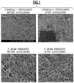
- Figure 1 illustrates scanning electron micrographs (SEMs) before and after autoclaving of chemically crosslinked PVA on ePTFE in comparison to the permanently hydrophilic ePTFE membranes prepared in accordance with the above process (i.e., e-beam irradiated). Autoclaving was performed for 30 minutes at 121 °C and 21 psi (144.8 kPa).
- the images of chemically cross-linked membrane samples before autoclaving and electron beam irradiated membrane samples before autoclaving in Figure 1 both show fibrils and nodes that are uniformly coated and devoid of coating agglomeration.
- the SEM images following autoclave show coating agglomeration due to polymer migration in the case of the chemically crosslinked PVA (see Figure 1 ).
- the SEM image following autoclave of PVA-MMA(2.4) coated on ePTFE shows no coating agglomeration (see Figure 1 ). This strongly suggests that the polymer is permanently attached to the porous substrate.
- Membranes according to embodiments of the disclosure may have differing dimensions, some selected with reference to application-specific criteria.
- the membrane may have a thickness in the direction of fluid flow in a range of less than about 10 micrometers.
- the membrane may have a thickness in the direction of fluid flow in a range of greater than about 10 micrometers, for example, in a range of from about 10 micrometers to about 100 micrometers, from about 100 micrometers to about 1 millimeter, from about 1 millimeter to about 5 millimeters, or greater than about 5 millimeters.
- the membrane may be formed from a plurality of differing layers.
- the membrane may have a width of greater than about 10 millimeters.
- the membrane may have a width in a range of from about 10 millimeters to about 45 millimeters, from about 45 millimeters to about 50 millimeters, from about 50 millimeters to about 10 centimeters, from about 10 centimeters to about 100 centimeters, from about 100 centimeters to about 500 centimeters, from about 500 centimeters to about 1 meter, or greater than about 1 meter.
- the width may be a diameter of a circular area, or may be the distance to the nearest peripheral edge of a polygonal area.
- the membrane may be rectangular, having a width in the meter range and an indeterminate length. That is, the membrane may be formed into a roll with the length determined by cutting the membrane at predetermined distances during a continuous formation operation.
- a membrane prepared according to embodiments of the disclosure may have one or more predetermined properties.
- Such properties may include one or more of a wettability of a dry-shipped membrane, a wet/dry cycling ability, filtering of polar liquid or solution, flow of non-aqueous liquid or solution, flow and/or permanence under low pH conditions, flow and/or permanence under high pH conditions, flow and/or permanence at room temperature conditions, flow and/or permanence at elevated temperature conditions, flow and/or permanence at elevated pressures, transparency to energy of predetermined wavelengths, transparency to acoustic energy, or support for catalytic material.
- Permanence further refers to the ability of the coating material to maintain function in a continuing manner, for example, for more than 1 day or more than one cycle (wet/dry, hot/cold, high/low pH, and the like).
- a property of at least one embodiment may include resistance to temperature excursions in a range of greater than about 100°C, for example, in autoclaving operations.
- the temperature excursion may be in a range of from about 100°C to about 125°C, from about 125°C to about 135°C, or from about 135°C to about 150°C.
- the temperature excursion also may be at an elevated pressure relative to ambient. The temperature excursion may be for a period of greater than about 15 minutes.
- UV radiation may allow for sterilization of the membrane, in one embodiment, without loss of properties.
- crosslinking of the hydrophilic coating may be initiated or facilitated by exposure to an irradiation source, such as an ultraviolet source, where UV initiators may compete with UV absorbing compositions, if present.
- Flow rate of fluid through the membrane may be dependent on one or more factors.
- the factors may include one or more of the physical and/or chemical properties of the membrane, the properties of the fluid (e.g., viscosity, pH, solute, and the like), environmental properties (e.g., temperature, pressure, and the like), and the like.
- the membrane may be permeable to vapor rather than, or in addition to, fluid or liquid.
- a suitable vapor transmission rate may be in a range of less than about 1000 grams per square meter per day (g/m 2 /day), from about 1000 g/m 2 /day to about 1500 g/m 2 /day, from about 1500 g/m 2 /day to about 2000 g/m 2 /day, or greater than about 2000 g/m 2 /day.
- the membrane may be selectively impermeable to liquid or fluid, while remaining permeable to vapor.
- the coated membranes described herein can be employed in numerous applications, including but not limited to, liquid filtration, water purification, chemical separations, charged ultrafiltration membranes, protein sequestration/purification, waste treatment membranes, biomedical applications, pervaporation, gas separation, the fuel cell industry, electrolysis, dialysis, cation-exchange resins, batteries, reverse osmosis, dielectrics/capacitors, industrial electrochemistry, SO 2 electrolysis, chloralkali production, and super acid catalysis.
- the composite compositions wet out completely, and demonstrate high fluxes of water and essentially no extractables over many autoclave cycles.
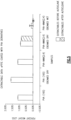
- Weight percent add-on or burn-off weight percents were calculated to determine the amount of e-beam reactive coating applied to the base membrane. Weight percent add-ons were calculated by: 100*(Membrane weight after coating-membrane weight before coating)/membrane weight before coating. Burn-off weight percents were determined by the following: the e-beam reactive coating was selectively removed from the porous substrate by thermal degradation at 204°C (400° F) for 20 minutes. Burn-off weight percents were calculated by: 100*(Membrane weight before burn-off - membrane weight after burn-off)/membrane weight after burn-off).
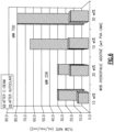
- Vacuum filtration was performed using a 47 mm diameter Millipore glass filter vacuum filtration apparatus. Flow rates of water were performed at 27 inches Hg (91,4 kPa) pressure differential and reported in mL/min-cm 2 .
- E-beam irradiation experiments were performed with equipment from Advanced Electron Beams Inc. in Wilmington, Massachusetts. 125 kV was used as a standard voltage (80-150 kV operating voltage range), unless otherwise noted. The unit was capable of giving a 50 kGy dose with each pass; higher dosages were obtained by using multiple passes. E-beam dosages were administered from 0 to 100 kGy.
- Extractables testing was done according to the following procedure. The membranes were dried at 70 °C for 1 hour to remove residual volatiles and weighed using a microbalance. Membranes were confined in a mesh screen and soaked in stirring water at 80 °C for 24 hours. The membranes were then dried at 70 °C for 1 hour and weighed using a microbalance. Percent extractables were determined by the weight percentage difference between the dried samples before and after extraction. Autoclaving was done using a Steris Sterilizer, Amsco Century SV-148H Prevac Steam Sterilizer at 121 °C and 21 psi (144.8 kPa) for 30 minutes.
- PVA-MMA(2.4) - high MW functionalized PVA was synthesized and is referred to as PVA-MMA(2.4) - high MW.
- PVA (20.1 g, 456 mmol, Celvol 165 from Celanese Ltd.) was added to a 500 mL three-necked round-bottom flask with anhydrous DMSO (175 mL) and stirred vigorously at 75 °C until a homogeneous solution was achieved. The reaction was cooled to 40 °C, and 2-isocyanatoethyl methacrylate (3.53 g, 22.8 mmol) was added slowly to the vigorously stirring solution. The viscous solution was stirred for 24 hours, and then cooled to room temperature.
- the polymer was precipitated into a 5:1 mixture of isopropanol:ether (800 mL total).
- the flocculent white solid was dried under vacuum at room temperature.
- 1 H NMR showed approximately 2.4% of the repeat units contained the graftable methacrylate linkage (21.5 g, 91% yield, 42% conversion).
- PVA-MMA 5.0 - high MW
- PVA 20.1 g, 456 mmol, Celvol 165 from Celanese Ltd.
- anhydrous DMSO 150 mL
- 2-isocyanatoethyl methacrylate 10.1 g, 65.1 mmol
- the viscous solution was stirred for 24 hours at 40 °C, and then cooled to room temperature.
- the polymer was precipitated into a 3:1 mixture of isopropanol:ether (700 mL total).
- the flocculent white solid was dried under vacuum at room temperature. 1 H NMR showed approximately 5% of the repeat units contained the graftable methacrylate linkage (24.0 g, 80% yield, 39% conversion).
- PVA-MMA 1.4
- PVA-MMA 1.4
- DMSO 200 mL
- 4-(dimethylamino)pyridine 2.22 g, 18.2 mmol
- 2-isocyanatoethyl methacrylate (1.41 g, 9.09 mol) was added slowly to the vigorously stirring solution.
- the viscous solution was stirred for 24 hours, and then cooled to room temperature.
- the polymer was precipitated into isopropanol (1200 mL total).
- the flocculent white solid was dried under vacuum at 40 °C.
- 1 H NMR showed approximately 1.4% of the repeat units contained the graftable methacrylate linkage (20.8 g, 97% yield, 70% conversion).
- PVA-MA (3.8) - high MW
- PVA (11.2 g, 254 mmol, Celvol 165 from Celanese Ltd.) was added to a 500 mL, three-necked round-bottom flask with anhydrous DMSO (200 mL) and stirred vigorously at 50 °C until a homogeneous solution was achieved. The reaction was cooled to room temperature, and triethylamine (2.50 g, 24.7 mmol) and methacrylic anhydride (1.98 g, 12.8 mmol) was added slowly to the vigorously stirring solution in an ice bath to control any exotherm.
- PVA-MA functionalized PVA
- PVA-MA 3.0 - high MW
- PVA 20.0 g, 454 mmol, Celvol 165 from Celanese Ltd.
- DMSO 200 g
- the reaction was cooled to 70 °C and triethylamine (2.85 g, 28.2 mmol) was added.
- glycidyl methacrylate (2.00 g, 14.1 mmol) was added slowly to the vigorously stirring solution.
- the viscous solution was stirred for 2 hours at 70 °C and cooled to 50 °C for 2 hours.
- the polymer was precipitated into a vigorously stirring solution of isopropanol (1.2 L) using a blender.
- the flocculent white solid was filtered, washed with isopropanol (500 mL) and methanol (750 mL), and dried under vacuum overnight at 40 °C to remove residual solvents.
- 1 H NMR spectroscopy showed that approximately 3.0% of the repeat units contained the graftable methacrylate linkage (20.5 g, 98% yield, 97% conversion).
- PVA-MA functionalized PVA
- PVA-MA 20.0 g, 454 mmol, Celvol 165 from Celanese Ltd.
- DMSO 200 g
- the reaction was cooled to 70 °C and triethylamine (2.48 g, 24.5 mmol) was added.
- glycidyl methacrylate (1.74 g, 12.3 mmol) was added slowly to the vigorously stirring solution.
- the viscous solution was stirred for 2 hours at 70 °C and cooled to 50 °C for 2 hours.
- the polymer was precipitated into a vigorously stirring solution of isopropanol (1.2 L) using a blender.
- the flocculent white solid was filtered, washed with isopropanol (500 mL) and methanol (750 mL), and dried under vacuum overnight at 40 °C to remove residual solvents.
- 1 H NMR spectroscopy showed approximately 2.5% of the repeat units contained the graftable methacrylate linkage (20.3 g, 97% yield, 93% conversion).
- PVA-MA functionalized PVA
- PVA-MA 2.0 - high MW
- PVA (20.0 g, 454 mmol, Celvol 165 from Celanese Ltd.) and DMSO (202 g) was added to a 500 mL, three-necked round-bottom flask equipped with a mechanical stirrer and stirred vigorously at 95 °C until a homogeneous solution was achieved.
- the reaction was cooled to 70 °C and triethylamine (1.94 g, 19.2 mmol) was added.
- glycidyl methacrylate (1.37 g, 9.62 mmol) was added slowly to the vigorously stirring solution.
- the viscous solution was stirred for 2 hours at 70 °C and cooled to 50 °C for 2 hours.
- the polymer was precipitated into a vigorously stirring solution of isopropanol (1.2 L) using a blender.
- the flocculent white solid was filtered, washed with isopropanol (500 mL) and methanol (750 mL), and dried under vacuum overnight at 40 °C to remove residual solvents.
- 1 H NMR spectroscopy showed approximately 2.0% of the repeat units contained the graftable methacrylate linkage (20.0 g, 97% yield, 95% conversion).
- PVA-MMA (3) functionalized PVA was synthesized and is referred to as PVA-MMA (3) - low MW.
- PVA 50.2 g, 1.14 mol, Celvol 107 from Celanese Ltd.
- DMSO 225 mL
- 2-isocyanatoethyl methacrylate (10.4 g, 0.067 mol) was added slowly to the vigorously stirring solution.
- the viscous solution was stirred for 24 hours, then cooled to room temperature.
- the polymer was precipitated into a 9:1 mixture of isopropanol:ether (1L total).
- PVA-PVAm-mal functionalized PVA was synthesized and is referred to as PVA-PVAm-mal.
- PVA-PVAm (5.01 g, 114 mmol, PVOH(88)-PVAm(12) L12 from Celanese Ltd.) was added to a 500 mL, three-necked round-bottom flask with deionized water (55 mL) and stirred at 100 °C until a homogeneous solution was achieved.
- Maleic anhydride (1.34 g, 13.7 mmol) was dissolved in THF (4 mL) and added slowly to the vigorously stirring solution. The solution initially became cloudy, and then turned clear over the course of 20 minutes. The viscous solution was stirred for 24 hours at reflux.
- PVA-PVAm-MMA functionalized PVA was synthesized and is referred to as PVA-PVAm-MMA.
- PVA-PVAm 5.02 g, 114 mmol, PVOH(94)-PVAm(6) L6 from Celanese Ltd.
- THF 50 mL
- 2-isocyanatoethyl methacrylate (1.06 g, 6.83 mmol) was added slowly to the stirring mixture.
- the heterogeneous mixture was stirred for 24 hours, and then the volatiles were removed in vacuo.
- ePTFE QM702 series membrane from GE Energy
- PVA-MMA 2.4 - high MW
- PVA-MMA 1.4
- PVA-MA 3.0
- PVA-MA 2.5
- PVA-MA 2.0
- PVA-MMA (3)
- PVA-PVAm-mal PVA-PVAm-MMA
- Coatings for PVA-MMA (1.4) - high MW, PVA-MMA (3) - low MW, PVA-PVAm-mal, and PVA-PVAm-MMA were performed in a similar fashion.
- Coatings for PVA-MA(3.0) - high MW, PVA-MA (2.5) - high MW, and PVA-MA (2.0) - high MW were also performed in a similar fashion, although isopropanol concentrations were increased to 50% of the total coating solution concentration.
- ePTFE QM702 series membrane from GE Energy
- PVA-MMA 5.0-high MW
- DMSO dimethyl methacrylate
- BHA ePTFE membrane based on BHA ePTFE Part # QM702, was wetted out fully in the PVA-MMA (5.0) solution and excess solution was removed by squeegee.
- the transparent coated ePTFE samples were constrained in polypropylene hoops and allowed to air dry. Weight percent add-ons were determined to be between 10-11 wt%.
- ePTFE (QM702 series membrane from GE Energy) was coated with PVA-MA (3.8), which had been prepared in accordance with Example 4.
- PVA-MA (3.8) (4.00 g) was dissolved in DMSO (96 g) at 50 °C.
- BHA ePTFE membrane based on BHA ePTFE Part # QM702, was wetted out fully in the PVA-MA (3.8) solution and excess solution was squeegeed off.
- the transparent coated ePTFE samples were constrained in polypropylene hoops and allowed to air dry. The coating was repeated to increase the weight percent add-ons. Final weight percent add-ons were determined to be between 10-11 wt%.
- coated PVA-derived ePTFE samples were e-beamed in a constrained environment (i.e., polypropylene hoops) by one of two methodologies.
- Dry samples were placed in the AEB e-beam apparatus and placed under a nitrogen blanket until the oxygen concentration was less than 200 ppm. At a standard voltage of 125 kV, the dry sample was exposed to the desired dosage.
- Wet The samples were sprayed with deionized water until complete wet out of the membranes was achieved (i.e., completely transparent). Excess water was removed by squeegee, wipe, or other standard technique to ensure no pooling of water occurred on the membrane.
- the samples were placed in the AEB e-beam apparatus and placed under a nitrogen blanket until the oxygen concentration was less than 200 ppm. At a standard voltage of 125 kV, the wet sample was exposed to the desired dosage.
- Flow rates of the sample membranes prepared in accordance with Examples 11-13 after e-beam and after autoclaving are provided in Table 1 below.
- Celvol 165 high molecular weight of ⁇ 146-186 kg/mol
- super hydrolyzed polyvinyl alcohol from Celanese Ltd.
- Flow rates were measured in mL/min-cm 2 @ 27" Hg (91,4 kPa).
- Weight percent add-ons were calculated by: 100*(Membrane weight after coating-membrane weight before coating)/membrane weight before coating.
- coated, PVA-derived ePTFE samples were e-beamed in a constrained environment (i.e., polypropylene hoops) by one of two methodologies: dry or wet. In all examined cases, the latter of the two methodologies proved to be the more effective technique for ensuring complete autoclavability.
- Autoclavability is defined as the membrane property of transparent wet out following an autoclave cycle. The wet methodology was performed as follows: the samples were sprayed with deionized water until complete wet out of the membranes was achieved (i.e., completely transparent). Excess water was removed by squeegee, wipe, or other standard technique to ensure no pooling of water occurred on the membrane.
- PVA-UMA(2.6) - high MW functionalized PVA was synthesized and is referred to as PVA-UMA(2.6) - high MW.
- PVA (20.0 g, 456 mmol, Celvol 165 from Celanese Ltd.) was added to a 500 mL three-necked round-bottom flask with anhydrous DMSO (220 g) and stirred vigorously at 75 °C until a homogeneous solution was achieved.
- BHT 2,6-Di-tert-butyl-4-methylphenol
- PVA-UMA(2.6) - high MW, 6 kg scale-up functionalized PVA was synthesized and is referred to as PVA-UMA(2.6) - high MW, 6 kg scale-up.
- DMSO (30 kg) was added to a Pfaudler glass-lined, 50-gallon (0.19 m 3 ), steel reactor equipped with a retreating curve agitator, baffle, and thermal well, in the Process Development Facility (PDF).
- PVA 6.0 kg, 136 mol, Celvol 165 from Celanese Ltd.
- Additional DMSO 36 kg was added to the stirring mixture. The mixture was slowly heated to 60 °C and stirred under air until a homogeneous solution was achieved.
- BHT 2,6-Di-tert-butyl-4-methylphenol
- 2-Isocyanatoethyl methacrylate 550 g, 11.8 mol
- the viscous solution was stirred for an additional 15 minutes, and a small aliquot was sampled for analysis.
- 1 H NMR spectroscopy in DMSO-d 6 showed 100% conversion.
- the reactor and its contents were cooled to RT overnight.
- the polymer (5L of solution at a time) was precipitated into a vigorously stirring solution of isopropanol (25 L) using a Henschel Homogenizer.
- the flocculent white solid was centrifuged, reslurried with isopropanol, and chopped with the Henschel.
- the polymer was then soaked in excess isopropanol ( ⁇ 6 kg in 200 L isopropanol) in large polypropylene drums for 4 days to remove residual DMSO in the polymer. The process was repeated again, and the polymer was re-soaked for another 5 days.
- the polymer was centrifuged at high speeds to dry, and the polymer was rechopped in the Henschel Homogenizer. 1 H NMR showed 2.6% of the repeat units contained the graftable methacrylate linkage (6.5 kg, 99% yield, 100% conversion).
- ePTFE QM702 series membrane from GE Energy
- PVA-UMA(2.6) was coated with PVA-UMA(2.6), which had been prepared in accordance with Example 18.
- PVA-UMA(2.6) (2.50 g) was dissolved in deionized water (98 g) at 50 °C.
- BHA ePTFE membrane based on BHA ePTFE Part # QM702, was wetted out fully in the PVA-UMA(2.6) solution and excess solution was squeegeed off.
- the transparent coated ePTFE samples were constrained in polypropylene hoops and allowed to air dry. Weight percent add-ons were determined to be between 6-10 wt%.
- ePTFE QM702 series membrane from GE Energy
- PVA-UMA(2.6) which had been prepared in accordance with Example 18 in combination with the desired hydrophilic additive at the desired weight percent.
- Particular additives and their respective weight percents evaluated are reported in Table 2, hereinbelow.
- a 30 wt% hydrophilic additive sample was prepared by adding 36 mg PEG-DA (average Mn 700 (g/mol)) to the 1.2% PVA-UMA solution made with 120 mg PVA-UMA.
- the transparent coated ePTFE samples were constrained in polypropylene hoops and allowed to air dry. Weight percent add-ons were determined to be between 6-8 wt%.
- coated PVA-derived ePTFE samples were e-beamed in a constrained environment (i.e., polypropylene hoops).
- the samples were sprayed with deionized water until complete wet-out of the membranes was achieved (i.e., completely transparent). Excess water was removed by squeegee, wipe, or other technique to ensure no pooling of water occurred on the membrane.
- the samples were placed in the AEB e-beam apparatus and placed under a nitrogen blanket until the oxygen concentration was less than 200 ppm. At a standard voltage of 125 kV, the wet sample was exposed to the desired dosage, i.e., either 5 or 10 kGy.
- Flow rates of the sample membranes prepared in accordance with Examples 18-22 after e-beam and after autoclaving are provided in Table 2 below.
- Membranes coated with PVA-UMA(2.6) alone are used as the control.
- ePTFE GE Energy Part # QM702; Roll 73965-1LB
- Flow rates were measured both before and after a 30-minute, 121°C, 1.5 atm (152 kPa) autoclave cycle.
- Figures 6 and 7 show graphically the flow rates of the coated membranes exposed to e-beam irradiation at 10 and 5 kGy, respectively.
- Table 2 Flow rates of the coated membranes exposed to e-beam irradiation at 10 and 5 kGy, respectively.
- the additive weight percents of hydrophilic additive are relative to the amount of PVA-UMA in solution.
- 30-wt% hydrophilic additive corresponds to 30 mg hydrophilic additive being added to a 1% PVA-UMA solution made with 100 mg PVA-UMA. All samples were wet out with water and then exposed to e-beam irradiation.
- Weight percent add-ons are calculated by: (membrane weight after coating - membrane weight before coating) / membrane weight before coating.
- c Based on a scale of 1 to 5 with 1 meaning completely opaque (no water wettability) and 5 meaning full transparency (complete water wet-out) using visual inspection of water wet-out on membranes.
- DI water flow rates are measured in mL/min-cm 2 @ 27" Hg (91,4 kPa) vacuum.
- PVA-UMA-coated ePTFE containing either the diacrylated (PEG-DA) and triacrylated (TMPET) additives were autoclavable and gave high water flow rates following autoclave.
- M n 700 and 2000 (g/mol) outperformed the samples with lower molecular weight PEG-DA (M n 258 (g/mol)).
- M n 700 and 2000 (g/mol) the samples with lower molecular weight PEG-DA
- 10 wt% additive was adequate to give uniformly autoclavable membranes and significant flow rates.
- Extractables is defined as the percentage of unbound material that is removed from the membrane following extraction in deionized water at 80 °C for 24 hours. Percent extractables were determined by the weight percentage difference between the dried samples before and after extraction. The goal is to get extractables levels as close to zero as possible.
- ePTFE that has been coated with a solution of PVA-UMA(2.6) and PEG-DA MW 700 (10 or 30 wt% PEG-DA with respect to PVA-UMA) was exposed to e-beam irradiation at 10 kGy.
- Extractables were measured both after e-beam exposure and after one autoclave cycle ( Figure 8 ). After e-beam, extractables of about 0.3 wt% were observed, whereas after autoclave, no extractables were detected. Table 3. Extractables data after e-beam and after autoclave for functionalized ePTFE samples coated with PVA-UMA(2.6) and a hydrophilic additive. Additive Wt% Additive Dose (kGy) After E-beam Std. Dev After Autoclave Std.
- the term “comprising” means various compositions, compounds, components, layers, steps and the like can be conjointly employed in the present invention. Accordingly, the term “comprising” encompasses the more restrictive terms “consisting essentially of” and “consisting of.”
Claims (11)
- Membrane comprenant :une membrane de base poreuse, laquelle membrane de base poreuse est hydrophobe ; etun revêtement hydrophile lié à la membrane de base poreuse, lequel revêtement hydrophile est préparé par :un additif hydrophile, lequel additif hydrophile comprend au moins un acrylate, diacrylate, triacrylate, polyacrylate, acrylamide, vinylcétone, styrénique, vinyléther, fragment contenant un vinyle ou allyle, et/ou benzyle et carbone tertiaire (CHR3), ou des combinaisons de ceux-ci ; etun polymère hydrophile ayant une masse moléculaire moyenne supérieure à 2500 Daltons et qui est dérivé avec un groupe réactif vis-à-vis d'un faisceau d'électrons, lequel polymère hydrophile comprend un polymère de poly(alcool vinylique) (PVA), un polymère de polyvinylamine (PVAm), et/ou un copolymère de poly(alcool vinylique)-polyvinylamine (PVA-PVAm), dans lequel le groupe réactif vis-à-vis d'un faisceau d'électrons est configuré pour lier de façon permanente le revêtement hydrophile à la membrane de base poreuse suite à une exposition à une irradiation par un faisceau d'électrons, et dans lequel le groupe réactif vis-à-vis d'un faisceau d'électrons comprend des méthacrylates, acrylates, et/ou acrylamides ; etpar irradiation du revêtement hydrophile avec une source de faisceau d'électrons.
- Membrane selon la revendication 1, dans laquelle le revêtement hydrophile contient un pourcentage en moles compris entre 0,1 % en moles et 10 % en moles des motifs de groupe réactif vis-à-vis d'un faisceau d'électrons par rapport au total des motifs répétitifs du polymère.
- Membrane selon l'une quelconque des revendications précédentes, dans laquelle le groupe réactif vis-à-vis d'un faisceau d'électrons est greffé de manière covalente à la membrane de base poreuse.
- Membrane selon l'une quelconque des revendications précédentes, dans laquelle la masse moléculaire du ou des additifs hydrophiles est de 250 g/mol à 100 000 g/mol.
- Membrane selon l'une quelconque des revendications précédentes, dans laquelle l'additif hydrophile comprend le diacrylate de polyéthylèneglycol, le diacrylate de tétra(éthylèneglycol), le diacrylate d'éther méthylique de triméthylolpropane éthoxylé, le diacrylate de 1,3-butanediol, le diacrylate de 1,3-diglycérolate de glycérol, le diacrylate de 1,6-hexanediol éthoxylé, le diacrylate de bisphénol A éthoxylé, le diacrylate de glycérolate de tripropylèneglycol, le diacrylate de polypropylèneglycol, le triacrylate de triméthylolpropane éthoxylé, le triacrylate de triméthylolpropane propoxylé, le diméthacrylate de polyéthylèneglycol, le diméthacrylate de polypropylèneglycol, le diméthacrylate de 1,3-butanediol, ou leurs combinaisons.
- Membrane selon l'une quelconque des revendications précédentes, dans laquelle l'additif hydrophile est présent en des quantités de 0,1 % en poids à 1000 % en poids par rapport au poids du polymère hydrophile dans le revêtement hydrophile.
- Membrane selon l'une quelconque des revendications précédentes, dans laquelle le revêtement hydrophile est présent en des quantités de 0,1 % en poids ajoutés à 100 % en poids ajoutés, par rapport au poids de la membrane de base, dans laquelle les pourcentages en poids ajoutés sont calculés par 100 * (poids de la membrane après le revêtement - poids de la membrane avant le revêtement / poids de la membrane avant le revêtement).
- Procédé pour former de façon permanente une surface hydrophile sur une membrane poreuse, le procédé comprenant :l'application d'un revêtement hydrophile comprenant un additif hydrophile, l'additif hydrophile comprenant au moins un acrylate, diacrylate, triacrylate, polyacrylate, acrylamide, vinylcétone, styrénique, vinyléther, fragment contenant un vinyle ou allyle, et/ou benzyle et carbone tertiaire (CHR3), ou des combinaisons de ceux-ci, et un polymère hydrophile ayant une masse moléculaire moyenne supérieure à 2500 Daltons et qui est dérivé avec un groupe réactif vis-à-vis d'un faisceau d'électrons à une membrane de base poreuse, dans laquelle le polymère hydrophile comprend un polymère de poly(alcool vinylique) (PVA), un polymère de polyvinylamine (PVAm), et/ou un copolymère de poly(alcool vinylique)-polyvinylamine (PVA-PVAm),dans lequel la membrane de base poreuse est hydrophobe, dans lequel le groupe réactif vis-à-vis d'un faisceau d'électrons comprend des méthacrylates, acrylates et/ou acrylamides,l'irradiation de la membrane de base poreuse revêtue avec une source de faisceau d'électrons, etle greffage de façon covalente des groupes réactifs vis-à-vis d'un faisceau d'électrons à la membrane de base poreuse pour former de façon permanente la surface hydrophile sur la membrane de base poreuse.
- Procédé selon la revendication 8, comprenant en outre l'application d'eau sur et le mouillage de la membrane de base poreuse revêtue avant l'irradiation.
- Procédé selon l'une quelconque des revendications 8 et 9, dans lequel la membrane a un pourcentage en poids ajouté et/ou un pourcentage en poids de perte par brûlage du revêtement hydrophile de 3 à 15 % en poids, dans lequel le pourcentage en poids ajouté est calculé par 100 * (poids de la membrane après le revêtement - poids de la membrane avant le revêtement / poids de la membrane avant le revêtement) et le pourcentage en poids de perte par brûlage est calculé par 100 * (poids de la membrane avant le brûlage - poids de la membrane après le brûlage / poids de la membrane après le brûlage), le revêtement étant éliminé de la membrane de base poreuse par dégradation thermique à 204°C (400°F) pendant 20 minutes.
- Procédé selon l'une quelconque des revendications 8 à 10, dans lequel l'irradiation de la membrane de base poreuse revêtue avec la source de faisceau d'électrons comprend l'exposition de la membrane de base poreuse revêtue à un faisceau d'électrons à une intensité d'irradiation située dans la plage allant de 0,1 kGy à 2000 kGy, de préférence à une intensité d'irradiation située dans la plage allant de 5 kGy à 40 kGy.
Applications Claiming Priority (2)
| Application Number | Priority Date | Filing Date | Title |
|---|---|---|---|
| US12/275,368 US10092881B2 (en) | 2008-01-25 | 2008-11-21 | Permanent hydrophilic porous coatings and methods of making them |
| EP09176385.4A EP2191888B1 (fr) | 2008-11-21 | 2009-11-18 | Revêtements poreux hydrophiles permanents et leurs procédés de fabrication utilisant faisceau d'électrons |
Related Parent Applications (1)
| Application Number | Title | Priority Date | Filing Date |
|---|---|---|---|
| EP09176385.4A Division EP2191888B1 (fr) | 2008-11-21 | 2009-11-18 | Revêtements poreux hydrophiles permanents et leurs procédés de fabrication utilisant faisceau d'électrons |
Publications (2)
| Publication Number | Publication Date |
|---|---|
| EP3210664A1 EP3210664A1 (fr) | 2017-08-30 |
| EP3210664B1 true EP3210664B1 (fr) | 2024-01-03 |
Family
ID=41683512
Family Applications (2)
| Application Number | Title | Priority Date | Filing Date |
|---|---|---|---|
| EP09176385.4A Active EP2191888B1 (fr) | 2008-11-21 | 2009-11-18 | Revêtements poreux hydrophiles permanents et leurs procédés de fabrication utilisant faisceau d'électrons |
| EP17163637.6A Active EP3210664B1 (fr) | 2008-11-21 | 2009-11-18 | Revêtements poreux hydrophiles permanents et leurs procédés de fabrication |
Family Applications Before (1)
| Application Number | Title | Priority Date | Filing Date |
|---|---|---|---|
| EP09176385.4A Active EP2191888B1 (fr) | 2008-11-21 | 2009-11-18 | Revêtements poreux hydrophiles permanents et leurs procédés de fabrication utilisant faisceau d'électrons |
Country Status (4)
| Country | Link |
|---|---|
| US (1) | US10092881B2 (fr) |
| EP (2) | EP2191888B1 (fr) |
| JP (1) | JP5773566B2 (fr) |
| CN (1) | CN101898432B (fr) |
Families Citing this family (32)
| Publication number | Priority date | Publication date | Assignee | Title |
|---|---|---|---|---|
| US20100077529A1 (en) * | 2005-09-30 | 2010-04-01 | General Electric Company | Article, laminate and associated methods |
| US20090205116A1 (en) * | 2005-09-30 | 2009-08-20 | General Electric Company | Article, laminate and associated methods |
| GB0901699D0 (en) | 2009-02-02 | 2009-03-11 | Ntnu Technology Transfer As | gas seperation membrane |
| CN102781558B (zh) * | 2009-11-25 | 2015-06-24 | 悉尼大学 | 膜及膜分离系统 |
| KR101136943B1 (ko) * | 2010-04-16 | 2012-04-20 | 한국과학기술연구원 | 내오염성이 향상된 친수성 분리막의 제조방법 및 상기 방법으로 제조된 친수성 분리막 |
| EP2633901A4 (fr) * | 2010-10-26 | 2014-09-17 | Toray Industries | Membrane de séparation, élément de membrane de séparation et procédé de production de membrane de séparation |
| US9508971B2 (en) | 2011-02-28 | 2016-11-29 | Nitto Denko Corporation | Gas-permeable filter provided with oil repellency |
| WO2012124745A1 (fr) * | 2011-03-14 | 2012-09-20 | 日本ゴア株式会社 | Filtre pour une filtration de traitement d'eau et son procédé de fabrication |
| EP2723479B1 (fr) * | 2011-06-23 | 2021-08-11 | Solvay Specialty Polymers Italy S.p.A. | Procédé de fabrication de membranes poreuses |
| US20130045399A1 (en) * | 2011-08-16 | 2013-02-21 | Primus Power Corporation | Flow Battery with Reactant Separation |
| US20130171669A1 (en) * | 2011-12-30 | 2013-07-04 | General Electric Company | Porous membranes having a hydrophilic coating and methods for their preparation and use |
| US20130171619A1 (en) * | 2011-12-30 | 2013-07-04 | General Electric Company | Porous membranes having a hydrophilic coating and methods for their preparation and use |
| JP6037643B2 (ja) * | 2012-04-06 | 2016-12-07 | 日東電工株式会社 | 撥油性が付与された通気フィルム |
| EP2918631A4 (fr) * | 2012-11-06 | 2016-07-06 | Sekisui Chemical Co Ltd | Film microporeux de résine synthétique résistant à la chaleur et procédé pour produire celui-ci, séparateur pour batterie secondaire à électrolyte non aqueux, et batterie secondaire à électrolyte non aqueux |
| US10384167B2 (en) | 2013-11-21 | 2019-08-20 | Oasys Water LLC | Systems and methods for improving performance of osmotically driven membrane systems |
| US11351509B2 (en) * | 2013-12-06 | 2022-06-07 | Taiwan Semiconductor Manufacturing Company, Ltd. | Filter with seal treatment |
| CN103862728B (zh) * | 2014-03-20 | 2016-08-17 | 江苏泛亚微透科技股份有限公司 | 汽车电气电子设备用持续单向透湿的涂层膜及其制造方法 |
| CN103862766B (zh) * | 2014-03-20 | 2016-01-27 | 江苏泛亚微透科技股份有限公司 | 汽车电气电子设备用涂层膜贴片及其制造方法 |
| SG10201507931QA (en) * | 2014-12-22 | 2016-07-28 | Emd Millipore Corp | Removal of microorganisms from cell culture media |
| US9643130B2 (en) | 2015-03-31 | 2017-05-09 | Pall Corporation | Hydrophilically modified fluorinated membrane (IV) |
| US9630151B2 (en) * | 2015-03-31 | 2017-04-25 | Pall Corporation | Hydrophilically modified fluorinated membrane (V) |
| CN107949403A (zh) | 2015-04-16 | 2018-04-20 | 好利司泰公司 | 亲水性涂层及其形成方法 |
| US9849428B2 (en) | 2015-04-30 | 2017-12-26 | Pall Corporation | Hydrophilically modified fluorinated membrane (VI) |
| CN105217998A (zh) * | 2015-09-18 | 2016-01-06 | 荣成复合材料有限公司 | 一种临时架桥材料 |
| US20170275814A1 (en) * | 2016-03-24 | 2017-09-28 | Apjet, Inc. | Method for coloring a substrate using atmospheric pressure plasma polymerization |
| US11404222B2 (en) * | 2017-11-13 | 2022-08-02 | Korea Advanced Institute Of Science And Technology | Apparatus for generating electrical energy based on hydrophilic fiber membrane and method of fabricating same |
| CN107938357B (zh) * | 2017-12-04 | 2020-01-10 | 上海雅运新材料有限公司 | 一种织物风格整理剂组合物及其制备方法 |
| WO2019174713A1 (fr) | 2018-03-12 | 2019-09-19 | Symrise Ag | Film adhésif de substance active |
| EP3873722A4 (fr) | 2018-11-01 | 2022-08-17 | Stratasys, Inc. | Procédé de séparation de construction vis-à-vis d'une interface de durcissement dans un processus de fabrication additive |
| US11104075B2 (en) | 2018-11-01 | 2021-08-31 | Stratasys, Inc. | System for window separation in an additive manufacturing process |
| WO2022229748A1 (fr) * | 2021-04-29 | 2022-11-03 | 3M Innovative Properties Company | Membranes polymères à surface modifiée et leur procédé de fabrication |
| WO2023217814A1 (fr) * | 2022-05-12 | 2023-11-16 | Merck Patent Gmbh | Traitements de surface pour membranes de purification |
Family Cites Families (41)
| Publication number | Priority date | Publication date | Assignee | Title |
|---|---|---|---|---|
| US2010115A (en) * | 1933-10-20 | 1935-08-06 | Mohawk Carpet Mills Inc | Loom |
| GB1538810A (en) | 1976-08-10 | 1979-01-24 | Sumitomo Electric Industries | Hydrophilic porous fluorocarbon structures and process for their production |
| IL70415A (en) | 1982-12-27 | 1987-07-31 | Aligena Ag | Semipermeable encapsulated membranes,their manufacture and their use |
| JPS63190602A (ja) | 1986-01-07 | 1988-08-08 | Mitsubishi Rayon Co Ltd | 親水化多孔質膜及びその製造方法 |
| US4917793A (en) | 1986-12-04 | 1990-04-17 | Pitt Aldo M | Transparent porous membrane having hydrophilic surface and process |
| US4806382A (en) | 1987-04-10 | 1989-02-21 | University Of Florida | Ocular implants and methods for their manufacture |
| US5100689A (en) | 1987-04-10 | 1992-03-31 | University Of Florida | Surface modified surgical instruments, devices, implants, contact lenses and the like |
| US4944879A (en) * | 1989-07-27 | 1990-07-31 | Millipore Corporation | Membrane having hydrophilic surface |
| DE69017197T2 (de) | 1990-05-18 | 1995-09-14 | Japan Gore Tex Inc | Hydrophile poröse Membrane aus Fluoropolymer. |
| US5049275A (en) * | 1990-06-15 | 1991-09-17 | Hoechst Celanese Corp. | Modified microporous structures |
| US5137633A (en) | 1991-06-26 | 1992-08-11 | Millipore Corporation | Hydrophobic membrane having hydrophilic and charged surface and process |
| US5391426A (en) | 1992-03-11 | 1995-02-21 | W. L. Gore & Associates, Inc. | Polyalkyleneimine coated material |
| US5209850A (en) | 1992-06-19 | 1993-05-11 | W. L. Gore & Associates, Inc. | Hydrophilic membranes |
| DE4243995C2 (de) * | 1992-12-23 | 1996-07-25 | Gore W L & Ass Gmbh | Permanente hydrophile Modifizierung für Fluorpolymere und Verfahren zur Erzeugung der Modifizierung |
| US5354587A (en) | 1993-11-15 | 1994-10-11 | W. L. Gore & Associates, Inc. | Hydrophilic compositions with increased thermal and solvent resistance |
| US5374334A (en) | 1993-12-06 | 1994-12-20 | Nalco Chemical Company | Class of polymeric adhesives for yankee dryer applications |
| US5849311A (en) | 1996-10-28 | 1998-12-15 | Biopolymerix, Inc. | Contact-killing non-leaching antimicrobial materials |
| ATE198996T1 (de) | 1994-07-28 | 2001-02-15 | Millipore Corp | Porösesverbundmembran und verfahren |
| US5874165A (en) * | 1996-06-03 | 1999-02-23 | Gore Enterprise Holdings, Inc. | Materials and method for the immobilization of bioactive species onto polymeric subtrates |
| US6306165B1 (en) | 1996-09-13 | 2001-10-23 | Meadox Medicals | ePTFE small caliber vascular grafts with significant patency enhancement via a surface coating which contains covalently bonded heparin |
| US6083393A (en) * | 1997-10-27 | 2000-07-04 | Pall Corporation | Hydrophilic membrane |
| US6395383B1 (en) | 1999-12-13 | 2002-05-28 | Gore Enterprise Holdings, Inc. | Chemical protective covering |
| US8192765B2 (en) | 2000-06-21 | 2012-06-05 | Icet, Inc. | Material compositions for microbial and chemical protection |
| MXPA04003603A (es) | 2001-10-19 | 2005-04-11 | Innovative Constr & Build Mat | Medios de filtracion de aire antipatogenos y dispositivos para manejar aire que tienen capacidades protectoras contra microorganismos infecciosos transportados por el aire. |
| EP1552878A4 (fr) | 2002-10-18 | 2006-03-22 | Asahi Kasei Pharma Corp | Membrane hydrophile microporeuse |
| US7704598B2 (en) | 2004-05-26 | 2010-04-27 | Gore Enterprise Holdings, Inc. | Durable covering for chemical protection |
| JP5011722B2 (ja) | 2004-12-24 | 2012-08-29 | 東レ株式会社 | 医療用分離膜の製造方法およびその医療用分離膜を用いた医療用分離膜モジュールの製造方法 |
| US20090117367A1 (en) | 2007-09-28 | 2009-05-07 | General Electric Company | Article and associated method |
| US7381331B2 (en) | 2005-09-30 | 2008-06-03 | General Electric Company | Hydrophilic membrane and associated method |
| US20090205116A1 (en) | 2005-09-30 | 2009-08-20 | General Electric Company | Article, laminate and associated methods |
| US20100077529A1 (en) | 2005-09-30 | 2010-04-01 | General Electric Company | Article, laminate and associated methods |
| US7631768B2 (en) | 2005-11-04 | 2009-12-15 | General Electric Company | Membrane and associated method |
| US7291696B2 (en) | 2005-11-04 | 2007-11-06 | General Electric Company | Composition and associated method |
| CN101300132A (zh) | 2005-11-07 | 2008-11-05 | 纳幕尔杜邦公司 | 可选择性渗透层压体的制造方法 |
| KR20080081001A (ko) * | 2005-12-30 | 2008-09-05 | 쓰리엠 이노베이티브 프로퍼티즈 컴파니 | 기능화 기판의 제조 방법 |
| US20070166344A1 (en) | 2006-01-18 | 2007-07-19 | Xin Qu | Non-leaching surface-active film compositions for microbial adhesion prevention |
| JP5391520B2 (ja) | 2006-02-21 | 2014-01-15 | 東レ株式会社 | 改質基材の製造方法 |
| EP2101991A1 (fr) | 2006-12-15 | 2009-09-23 | E. I. Du Pont de Nemours and Company | Laminés de films de polysaccharide acide |
| JP5376485B2 (ja) | 2007-02-21 | 2013-12-25 | 独立行政法人日本原子力研究開発機構 | アルキルグラフト鎖からなる高分子電解質膜、及び、その製造方法 |
| US20090239435A1 (en) | 2008-03-19 | 2009-09-24 | General Electric Company | Protective suit and methods of manufacture thereof |
| US20120135658A1 (en) | 2008-09-30 | 2012-05-31 | General Electric Company | Protective article and methods of manufacture thereof |
-
2008
- 2008-11-21 US US12/275,368 patent/US10092881B2/en active Active
-
2009
- 2009-11-02 JP JP2009251576A patent/JP5773566B2/ja active Active
- 2009-11-18 EP EP09176385.4A patent/EP2191888B1/fr active Active
- 2009-11-18 EP EP17163637.6A patent/EP3210664B1/fr active Active
- 2009-11-20 CN CN200910247118.3A patent/CN101898432B/zh not_active Expired - Fee Related
Also Published As
| Publication number | Publication date |
|---|---|
| JP5773566B2 (ja) | 2015-09-02 |
| EP2191888B1 (fr) | 2017-04-12 |
| EP2191888A1 (fr) | 2010-06-02 |
| CN101898432B (zh) | 2015-06-17 |
| US20090188857A1 (en) | 2009-07-30 |
| CN101898432A (zh) | 2010-12-01 |
| US10092881B2 (en) | 2018-10-09 |
| EP3210664A1 (fr) | 2017-08-30 |
| JP2010121127A (ja) | 2010-06-03 |
Similar Documents
| Publication | Publication Date | Title |
|---|---|---|
| EP3210664B1 (fr) | Revêtements poreux hydrophiles permanents et leurs procédés de fabrication | |
| US20090191399A1 (en) | Permanent hydrophilic porous coatings onto a substrate and porous membranes thereof | |
| US20090191357A1 (en) | Processes for forming permanent hydrophilic porous coatings onto a substrate, and porous membranes thereof | |
| US20090191398A1 (en) | Membranes comprising hydrophilic coatings | |
| US20100143611A1 (en) | Methods for making an asymmetric composite membrane | |
| EP1545739B1 (fr) | Membrane composite poreuse et procede de fabrication associe | |
| JP4677230B2 (ja) | 耐腐食性かつ低い蛋白質結合性表面を有する多孔質膜基体 | |
| US20030077435A1 (en) | Novel coated membranes and other articles | |
| JP2010053361A (ja) | 親水性膜の製造方法及びその多孔質膜 | |
| WO2009086347A1 (fr) | Procédé de réalisation d'une membrane fonctionnalisée | |
| CN1159770A (zh) | 多孔复合膜及其制法 | |
| AU2018263979A1 (en) | Asymmetric composite membranes and modified substrates used in their preparation | |
| WO2020202044A1 (fr) | Membranes composites | |
| Niu et al. | Modification of a polyethersulfone membrane with a block copolymer brush of poly (2-methacryloyloxyethyl phosphorylcholine-co-glycidyl methacrylate) and a branched polypeptide chain of Arg–Glu–Asp–Val | |
| AU2020359065A1 (en) | Durable membranes, their preparation and use | |
| KR101243939B1 (ko) | 폴리설폰의 친수화를 이용한 분리막의 제조방법 및 이에 따라 제조되는 폴리설폰 분리막 | |
| JP2004154613A (ja) | 機能性多孔膜の製造方法 | |
| US20220161204A1 (en) | Durable membranes, their preparation and use | |
| US20210016554A1 (en) | Asymmetric composite membranes and hydrophilicitized microporous sheets of polyolefin used in their preparation | |
| Khulbe et al. | Surface modification of synthetic polymeric membranes for filtration and gas separation |
Legal Events
| Date | Code | Title | Description |
|---|---|---|---|
| PUAI | Public reference made under article 153(3) epc to a published international application that has entered the european phase |
Free format text: ORIGINAL CODE: 0009012 |
|
| STAA | Information on the status of an ep patent application or granted ep patent |
Free format text: STATUS: THE APPLICATION HAS BEEN PUBLISHED |
|
| AC | Divisional application: reference to earlier application |
Ref document number: 2191888 Country of ref document: EP Kind code of ref document: P |
|
| AK | Designated contracting states |
Kind code of ref document: A1 Designated state(s): AT BE BG CH CY CZ DE DK EE ES FI FR GB GR HR HU IE IS IT LI LT LU LV MC MK MT NL NO PL PT RO SE SI SK SM TR |
|
| STAA | Information on the status of an ep patent application or granted ep patent |
Free format text: STATUS: REQUEST FOR EXAMINATION WAS MADE |
|
| 17P | Request for examination filed |
Effective date: 20180226 |
|
| RBV | Designated contracting states (corrected) |
Designated state(s): AT BE BG CH CY CZ DE DK EE ES FI FR GB GR HR HU IE IS IT LI LT LU LV MC MK MT NL NO PL PT RO SE SI SK SM TR |
|
| STAA | Information on the status of an ep patent application or granted ep patent |
Free format text: STATUS: EXAMINATION IS IN PROGRESS |
|
| 17Q | First examination report despatched |
Effective date: 20180920 |
|
| RIN1 | Information on inventor provided before grant (corrected) |
Inventor name: MOORE, DAVID ROGER Inventor name: HUTCHINSON, RYAN AUSTIN |
|
| STAA | Information on the status of an ep patent application or granted ep patent |
Free format text: STATUS: EXAMINATION IS IN PROGRESS |
|
| RAP1 | Party data changed (applicant data changed or rights of an application transferred) |
Owner name: PARKER-HANNIFIN CORPORATION |
|
| STAA | Information on the status of an ep patent application or granted ep patent |
Free format text: STATUS: EXAMINATION IS IN PROGRESS |
|
| GRAP | Despatch of communication of intention to grant a patent |
Free format text: ORIGINAL CODE: EPIDOSNIGR1 |
|
| STAA | Information on the status of an ep patent application or granted ep patent |
Free format text: STATUS: GRANT OF PATENT IS INTENDED |
|
| P01 | Opt-out of the competence of the unified patent court (upc) registered |
Effective date: 20230524 |
|
| INTG | Intention to grant announced |
Effective date: 20230616 |
|
| GRAS | Grant fee paid |
Free format text: ORIGINAL CODE: EPIDOSNIGR3 |
|
| GRAA | (expected) grant |
Free format text: ORIGINAL CODE: 0009210 |
|
| STAA | Information on the status of an ep patent application or granted ep patent |
Free format text: STATUS: THE PATENT HAS BEEN GRANTED |
|
| AC | Divisional application: reference to earlier application |
Ref document number: 2191888 Country of ref document: EP Kind code of ref document: P |
|
| AK | Designated contracting states |
Kind code of ref document: B1 Designated state(s): AT BE BG CH CY CZ DE DK EE ES FI FR GB GR HR HU IE IS IT LI LT LU LV MC MK MT NL NO PL PT RO SE SI SK SM TR |
|
| REG | Reference to a national code |
Ref country code: GB Ref legal event code: FG4D |
|
| REG | Reference to a national code |
Ref country code: CH Ref legal event code: EP |
|
| REG | Reference to a national code |
Ref country code: DE Ref legal event code: R096 Ref document number: 602009065160 Country of ref document: DE |
|
| REG | Reference to a national code |
Ref country code: IE Ref legal event code: FG4D |