EP3209904B1 - Drive unit for a motor vehicle, motor vehicle, and method for operating a motor vehicle - Google Patents
Drive unit for a motor vehicle, motor vehicle, and method for operating a motor vehicle Download PDFInfo
- Publication number
- EP3209904B1 EP3209904B1 EP15781027.6A EP15781027A EP3209904B1 EP 3209904 B1 EP3209904 B1 EP 3209904B1 EP 15781027 A EP15781027 A EP 15781027A EP 3209904 B1 EP3209904 B1 EP 3209904B1
- Authority
- EP
- European Patent Office
- Prior art keywords
- torque
- planetary gear
- gear
- drive
- motor
- Prior art date
- Legal status (The legal status is an assumption and is not a legal conclusion. Google has not performed a legal analysis and makes no representation as to the accuracy of the status listed.)
- Active
Links
- 238000000034 method Methods 0.000 title claims description 7
- 230000005540 biological transmission Effects 0.000 claims description 60
- 230000008878 coupling Effects 0.000 claims description 19
- 238000010168 coupling process Methods 0.000 claims description 19
- 238000005859 coupling reaction Methods 0.000 claims description 19
- 238000009826 distribution Methods 0.000 claims description 17
- 238000004146 energy storage Methods 0.000 claims description 5
- 238000013519 translation Methods 0.000 description 6
- 230000014616 translation Effects 0.000 description 6
- 238000010276 construction Methods 0.000 description 3
- 230000006978 adaptation Effects 0.000 description 2
- 238000009987 spinning Methods 0.000 description 2
- 230000009471 action Effects 0.000 description 1
- 230000000903 blocking effect Effects 0.000 description 1
- 230000008859 change Effects 0.000 description 1
- 210000000078 claw Anatomy 0.000 description 1
- 238000002485 combustion reaction Methods 0.000 description 1
- 230000001419 dependent effect Effects 0.000 description 1
- 238000004519 manufacturing process Methods 0.000 description 1
- 230000009467 reduction Effects 0.000 description 1
Images


Classifications
-
- F—MECHANICAL ENGINEERING; LIGHTING; HEATING; WEAPONS; BLASTING
- F16—ENGINEERING ELEMENTS AND UNITS; GENERAL MEASURES FOR PRODUCING AND MAINTAINING EFFECTIVE FUNCTIONING OF MACHINES OR INSTALLATIONS; THERMAL INSULATION IN GENERAL
- F16H—GEARING
- F16H48/00—Differential gearings
- F16H48/36—Differential gearings characterised by intentionally generating speed difference between outputs
-
- B—PERFORMING OPERATIONS; TRANSPORTING
- B60—VEHICLES IN GENERAL
- B60K—ARRANGEMENT OR MOUNTING OF PROPULSION UNITS OR OF TRANSMISSIONS IN VEHICLES; ARRANGEMENT OR MOUNTING OF PLURAL DIVERSE PRIME-MOVERS IN VEHICLES; AUXILIARY DRIVES FOR VEHICLES; INSTRUMENTATION OR DASHBOARDS FOR VEHICLES; ARRANGEMENTS IN CONNECTION WITH COOLING, AIR INTAKE, GAS EXHAUST OR FUEL SUPPLY OF PROPULSION UNITS IN VEHICLES
- B60K1/00—Arrangement or mounting of electrical propulsion units
-
- B—PERFORMING OPERATIONS; TRANSPORTING
- B60—VEHICLES IN GENERAL
- B60K—ARRANGEMENT OR MOUNTING OF PROPULSION UNITS OR OF TRANSMISSIONS IN VEHICLES; ARRANGEMENT OR MOUNTING OF PLURAL DIVERSE PRIME-MOVERS IN VEHICLES; AUXILIARY DRIVES FOR VEHICLES; INSTRUMENTATION OR DASHBOARDS FOR VEHICLES; ARRANGEMENTS IN CONNECTION WITH COOLING, AIR INTAKE, GAS EXHAUST OR FUEL SUPPLY OF PROPULSION UNITS IN VEHICLES
- B60K17/00—Arrangement or mounting of transmissions in vehicles
- B60K17/34—Arrangement or mounting of transmissions in vehicles for driving both front and rear wheels, e.g. four wheel drive vehicles
- B60K17/348—Arrangement or mounting of transmissions in vehicles for driving both front and rear wheels, e.g. four wheel drive vehicles having differential means for driving one set of wheels, e.g. the front, at one speed and the other set, e.g. the rear, at a different speed
- B60K17/35—Arrangement or mounting of transmissions in vehicles for driving both front and rear wheels, e.g. four wheel drive vehicles having differential means for driving one set of wheels, e.g. the front, at one speed and the other set, e.g. the rear, at a different speed including arrangements for suppressing or influencing the power transfer, e.g. viscous clutches
-
- B—PERFORMING OPERATIONS; TRANSPORTING
- B60—VEHICLES IN GENERAL
- B60K—ARRANGEMENT OR MOUNTING OF PROPULSION UNITS OR OF TRANSMISSIONS IN VEHICLES; ARRANGEMENT OR MOUNTING OF PLURAL DIVERSE PRIME-MOVERS IN VEHICLES; AUXILIARY DRIVES FOR VEHICLES; INSTRUMENTATION OR DASHBOARDS FOR VEHICLES; ARRANGEMENTS IN CONNECTION WITH COOLING, AIR INTAKE, GAS EXHAUST OR FUEL SUPPLY OF PROPULSION UNITS IN VEHICLES
- B60K6/00—Arrangement or mounting of plural diverse prime-movers for mutual or common propulsion, e.g. hybrid propulsion systems comprising electric motors and internal combustion engines ; Control systems therefor, i.e. systems controlling two or more prime movers, or controlling one of these prime movers and any of the transmission, drive or drive units Informative references: mechanical gearings with secondary electric drive F16H3/72; arrangements for handling mechanical energy structurally associated with the dynamo-electric machine H02K7/00; machines comprising structurally interrelated motor and generator parts H02K51/00; dynamo-electric machines not otherwise provided for in H02K see H02K99/00
- B60K6/20—Arrangement or mounting of plural diverse prime-movers for mutual or common propulsion, e.g. hybrid propulsion systems comprising electric motors and internal combustion engines ; Control systems therefor, i.e. systems controlling two or more prime movers, or controlling one of these prime movers and any of the transmission, drive or drive units Informative references: mechanical gearings with secondary electric drive F16H3/72; arrangements for handling mechanical energy structurally associated with the dynamo-electric machine H02K7/00; machines comprising structurally interrelated motor and generator parts H02K51/00; dynamo-electric machines not otherwise provided for in H02K see H02K99/00 the prime-movers consisting of electric motors and internal combustion engines, e.g. HEVs
- B60K6/22—Arrangement or mounting of plural diverse prime-movers for mutual or common propulsion, e.g. hybrid propulsion systems comprising electric motors and internal combustion engines ; Control systems therefor, i.e. systems controlling two or more prime movers, or controlling one of these prime movers and any of the transmission, drive or drive units Informative references: mechanical gearings with secondary electric drive F16H3/72; arrangements for handling mechanical energy structurally associated with the dynamo-electric machine H02K7/00; machines comprising structurally interrelated motor and generator parts H02K51/00; dynamo-electric machines not otherwise provided for in H02K see H02K99/00 the prime-movers consisting of electric motors and internal combustion engines, e.g. HEVs characterised by apparatus, components or means specially adapted for HEVs
- B60K6/36—Arrangement or mounting of plural diverse prime-movers for mutual or common propulsion, e.g. hybrid propulsion systems comprising electric motors and internal combustion engines ; Control systems therefor, i.e. systems controlling two or more prime movers, or controlling one of these prime movers and any of the transmission, drive or drive units Informative references: mechanical gearings with secondary electric drive F16H3/72; arrangements for handling mechanical energy structurally associated with the dynamo-electric machine H02K7/00; machines comprising structurally interrelated motor and generator parts H02K51/00; dynamo-electric machines not otherwise provided for in H02K see H02K99/00 the prime-movers consisting of electric motors and internal combustion engines, e.g. HEVs characterised by apparatus, components or means specially adapted for HEVs characterised by the transmission gearings
- B60K6/365—Arrangement or mounting of plural diverse prime-movers for mutual or common propulsion, e.g. hybrid propulsion systems comprising electric motors and internal combustion engines ; Control systems therefor, i.e. systems controlling two or more prime movers, or controlling one of these prime movers and any of the transmission, drive or drive units Informative references: mechanical gearings with secondary electric drive F16H3/72; arrangements for handling mechanical energy structurally associated with the dynamo-electric machine H02K7/00; machines comprising structurally interrelated motor and generator parts H02K51/00; dynamo-electric machines not otherwise provided for in H02K see H02K99/00 the prime-movers consisting of electric motors and internal combustion engines, e.g. HEVs characterised by apparatus, components or means specially adapted for HEVs characterised by the transmission gearings with the gears having orbital motion
-
- B—PERFORMING OPERATIONS; TRANSPORTING
- B60—VEHICLES IN GENERAL
- B60K—ARRANGEMENT OR MOUNTING OF PROPULSION UNITS OR OF TRANSMISSIONS IN VEHICLES; ARRANGEMENT OR MOUNTING OF PLURAL DIVERSE PRIME-MOVERS IN VEHICLES; AUXILIARY DRIVES FOR VEHICLES; INSTRUMENTATION OR DASHBOARDS FOR VEHICLES; ARRANGEMENTS IN CONNECTION WITH COOLING, AIR INTAKE, GAS EXHAUST OR FUEL SUPPLY OF PROPULSION UNITS IN VEHICLES
- B60K6/00—Arrangement or mounting of plural diverse prime-movers for mutual or common propulsion, e.g. hybrid propulsion systems comprising electric motors and internal combustion engines ; Control systems therefor, i.e. systems controlling two or more prime movers, or controlling one of these prime movers and any of the transmission, drive or drive units Informative references: mechanical gearings with secondary electric drive F16H3/72; arrangements for handling mechanical energy structurally associated with the dynamo-electric machine H02K7/00; machines comprising structurally interrelated motor and generator parts H02K51/00; dynamo-electric machines not otherwise provided for in H02K see H02K99/00
- B60K6/20—Arrangement or mounting of plural diverse prime-movers for mutual or common propulsion, e.g. hybrid propulsion systems comprising electric motors and internal combustion engines ; Control systems therefor, i.e. systems controlling two or more prime movers, or controlling one of these prime movers and any of the transmission, drive or drive units Informative references: mechanical gearings with secondary electric drive F16H3/72; arrangements for handling mechanical energy structurally associated with the dynamo-electric machine H02K7/00; machines comprising structurally interrelated motor and generator parts H02K51/00; dynamo-electric machines not otherwise provided for in H02K see H02K99/00 the prime-movers consisting of electric motors and internal combustion engines, e.g. HEVs
- B60K6/42—Arrangement or mounting of plural diverse prime-movers for mutual or common propulsion, e.g. hybrid propulsion systems comprising electric motors and internal combustion engines ; Control systems therefor, i.e. systems controlling two or more prime movers, or controlling one of these prime movers and any of the transmission, drive or drive units Informative references: mechanical gearings with secondary electric drive F16H3/72; arrangements for handling mechanical energy structurally associated with the dynamo-electric machine H02K7/00; machines comprising structurally interrelated motor and generator parts H02K51/00; dynamo-electric machines not otherwise provided for in H02K see H02K99/00 the prime-movers consisting of electric motors and internal combustion engines, e.g. HEVs characterised by the architecture of the hybrid electric vehicle
- B60K6/48—Parallel type
-
- B—PERFORMING OPERATIONS; TRANSPORTING
- B60—VEHICLES IN GENERAL
- B60K—ARRANGEMENT OR MOUNTING OF PROPULSION UNITS OR OF TRANSMISSIONS IN VEHICLES; ARRANGEMENT OR MOUNTING OF PLURAL DIVERSE PRIME-MOVERS IN VEHICLES; AUXILIARY DRIVES FOR VEHICLES; INSTRUMENTATION OR DASHBOARDS FOR VEHICLES; ARRANGEMENTS IN CONNECTION WITH COOLING, AIR INTAKE, GAS EXHAUST OR FUEL SUPPLY OF PROPULSION UNITS IN VEHICLES
- B60K6/00—Arrangement or mounting of plural diverse prime-movers for mutual or common propulsion, e.g. hybrid propulsion systems comprising electric motors and internal combustion engines ; Control systems therefor, i.e. systems controlling two or more prime movers, or controlling one of these prime movers and any of the transmission, drive or drive units Informative references: mechanical gearings with secondary electric drive F16H3/72; arrangements for handling mechanical energy structurally associated with the dynamo-electric machine H02K7/00; machines comprising structurally interrelated motor and generator parts H02K51/00; dynamo-electric machines not otherwise provided for in H02K see H02K99/00
- B60K6/20—Arrangement or mounting of plural diverse prime-movers for mutual or common propulsion, e.g. hybrid propulsion systems comprising electric motors and internal combustion engines ; Control systems therefor, i.e. systems controlling two or more prime movers, or controlling one of these prime movers and any of the transmission, drive or drive units Informative references: mechanical gearings with secondary electric drive F16H3/72; arrangements for handling mechanical energy structurally associated with the dynamo-electric machine H02K7/00; machines comprising structurally interrelated motor and generator parts H02K51/00; dynamo-electric machines not otherwise provided for in H02K see H02K99/00 the prime-movers consisting of electric motors and internal combustion engines, e.g. HEVs
- B60K6/50—Architecture of the driveline characterised by arrangement or kind of transmission units
- B60K6/52—Driving a plurality of drive axles, e.g. four-wheel drive
-
- B—PERFORMING OPERATIONS; TRANSPORTING
- B60—VEHICLES IN GENERAL
- B60W—CONJOINT CONTROL OF VEHICLE SUB-UNITS OF DIFFERENT TYPE OR DIFFERENT FUNCTION; CONTROL SYSTEMS SPECIALLY ADAPTED FOR HYBRID VEHICLES; ROAD VEHICLE DRIVE CONTROL SYSTEMS FOR PURPOSES NOT RELATED TO THE CONTROL OF A PARTICULAR SUB-UNIT
- B60W10/00—Conjoint control of vehicle sub-units of different type or different function
- B60W10/04—Conjoint control of vehicle sub-units of different type or different function including control of propulsion units
- B60W10/08—Conjoint control of vehicle sub-units of different type or different function including control of propulsion units including control of electric propulsion units, e.g. motors or generators
-
- F—MECHANICAL ENGINEERING; LIGHTING; HEATING; WEAPONS; BLASTING
- F16—ENGINEERING ELEMENTS AND UNITS; GENERAL MEASURES FOR PRODUCING AND MAINTAINING EFFECTIVE FUNCTIONING OF MACHINES OR INSTALLATIONS; THERMAL INSULATION IN GENERAL
- F16H—GEARING
- F16H48/00—Differential gearings
- F16H48/06—Differential gearings with gears having orbital motion
- F16H48/08—Differential gearings with gears having orbital motion comprising bevel gears
-
- F—MECHANICAL ENGINEERING; LIGHTING; HEATING; WEAPONS; BLASTING
- F16—ENGINEERING ELEMENTS AND UNITS; GENERAL MEASURES FOR PRODUCING AND MAINTAINING EFFECTIVE FUNCTIONING OF MACHINES OR INSTALLATIONS; THERMAL INSULATION IN GENERAL
- F16H—GEARING
- F16H48/00—Differential gearings
- F16H48/06—Differential gearings with gears having orbital motion
- F16H48/10—Differential gearings with gears having orbital motion with orbital spur gears
-
- B—PERFORMING OPERATIONS; TRANSPORTING
- B60—VEHICLES IN GENERAL
- B60K—ARRANGEMENT OR MOUNTING OF PROPULSION UNITS OR OF TRANSMISSIONS IN VEHICLES; ARRANGEMENT OR MOUNTING OF PLURAL DIVERSE PRIME-MOVERS IN VEHICLES; AUXILIARY DRIVES FOR VEHICLES; INSTRUMENTATION OR DASHBOARDS FOR VEHICLES; ARRANGEMENTS IN CONNECTION WITH COOLING, AIR INTAKE, GAS EXHAUST OR FUEL SUPPLY OF PROPULSION UNITS IN VEHICLES
- B60K17/00—Arrangement or mounting of transmissions in vehicles
- B60K17/04—Arrangement or mounting of transmissions in vehicles characterised by arrangement, location, or kind of gearing
- B60K17/16—Arrangement or mounting of transmissions in vehicles characterised by arrangement, location, or kind of gearing of differential gearing
-
- B—PERFORMING OPERATIONS; TRANSPORTING
- B60—VEHICLES IN GENERAL
- B60K—ARRANGEMENT OR MOUNTING OF PROPULSION UNITS OR OF TRANSMISSIONS IN VEHICLES; ARRANGEMENT OR MOUNTING OF PLURAL DIVERSE PRIME-MOVERS IN VEHICLES; AUXILIARY DRIVES FOR VEHICLES; INSTRUMENTATION OR DASHBOARDS FOR VEHICLES; ARRANGEMENTS IN CONNECTION WITH COOLING, AIR INTAKE, GAS EXHAUST OR FUEL SUPPLY OF PROPULSION UNITS IN VEHICLES
- B60K1/00—Arrangement or mounting of electrical propulsion units
- B60K2001/001—Arrangement or mounting of electrical propulsion units one motor mounted on a propulsion axle for rotating right and left wheels of this axle
-
- B—PERFORMING OPERATIONS; TRANSPORTING
- B60—VEHICLES IN GENERAL
- B60K—ARRANGEMENT OR MOUNTING OF PROPULSION UNITS OR OF TRANSMISSIONS IN VEHICLES; ARRANGEMENT OR MOUNTING OF PLURAL DIVERSE PRIME-MOVERS IN VEHICLES; AUXILIARY DRIVES FOR VEHICLES; INSTRUMENTATION OR DASHBOARDS FOR VEHICLES; ARRANGEMENTS IN CONNECTION WITH COOLING, AIR INTAKE, GAS EXHAUST OR FUEL SUPPLY OF PROPULSION UNITS IN VEHICLES
- B60K6/00—Arrangement or mounting of plural diverse prime-movers for mutual or common propulsion, e.g. hybrid propulsion systems comprising electric motors and internal combustion engines ; Control systems therefor, i.e. systems controlling two or more prime movers, or controlling one of these prime movers and any of the transmission, drive or drive units Informative references: mechanical gearings with secondary electric drive F16H3/72; arrangements for handling mechanical energy structurally associated with the dynamo-electric machine H02K7/00; machines comprising structurally interrelated motor and generator parts H02K51/00; dynamo-electric machines not otherwise provided for in H02K see H02K99/00
- B60K6/20—Arrangement or mounting of plural diverse prime-movers for mutual or common propulsion, e.g. hybrid propulsion systems comprising electric motors and internal combustion engines ; Control systems therefor, i.e. systems controlling two or more prime movers, or controlling one of these prime movers and any of the transmission, drive or drive units Informative references: mechanical gearings with secondary electric drive F16H3/72; arrangements for handling mechanical energy structurally associated with the dynamo-electric machine H02K7/00; machines comprising structurally interrelated motor and generator parts H02K51/00; dynamo-electric machines not otherwise provided for in H02K see H02K99/00 the prime-movers consisting of electric motors and internal combustion engines, e.g. HEVs
- B60K6/22—Arrangement or mounting of plural diverse prime-movers for mutual or common propulsion, e.g. hybrid propulsion systems comprising electric motors and internal combustion engines ; Control systems therefor, i.e. systems controlling two or more prime movers, or controlling one of these prime movers and any of the transmission, drive or drive units Informative references: mechanical gearings with secondary electric drive F16H3/72; arrangements for handling mechanical energy structurally associated with the dynamo-electric machine H02K7/00; machines comprising structurally interrelated motor and generator parts H02K51/00; dynamo-electric machines not otherwise provided for in H02K see H02K99/00 the prime-movers consisting of electric motors and internal combustion engines, e.g. HEVs characterised by apparatus, components or means specially adapted for HEVs
- B60K6/38—Arrangement or mounting of plural diverse prime-movers for mutual or common propulsion, e.g. hybrid propulsion systems comprising electric motors and internal combustion engines ; Control systems therefor, i.e. systems controlling two or more prime movers, or controlling one of these prime movers and any of the transmission, drive or drive units Informative references: mechanical gearings with secondary electric drive F16H3/72; arrangements for handling mechanical energy structurally associated with the dynamo-electric machine H02K7/00; machines comprising structurally interrelated motor and generator parts H02K51/00; dynamo-electric machines not otherwise provided for in H02K see H02K99/00 the prime-movers consisting of electric motors and internal combustion engines, e.g. HEVs characterised by apparatus, components or means specially adapted for HEVs characterised by the driveline clutches
- B60K2006/381—Arrangement or mounting of plural diverse prime-movers for mutual or common propulsion, e.g. hybrid propulsion systems comprising electric motors and internal combustion engines ; Control systems therefor, i.e. systems controlling two or more prime movers, or controlling one of these prime movers and any of the transmission, drive or drive units Informative references: mechanical gearings with secondary electric drive F16H3/72; arrangements for handling mechanical energy structurally associated with the dynamo-electric machine H02K7/00; machines comprising structurally interrelated motor and generator parts H02K51/00; dynamo-electric machines not otherwise provided for in H02K see H02K99/00 the prime-movers consisting of electric motors and internal combustion engines, e.g. HEVs characterised by apparatus, components or means specially adapted for HEVs characterised by the driveline clutches characterized by driveline brakes
-
- B—PERFORMING OPERATIONS; TRANSPORTING
- B60—VEHICLES IN GENERAL
- B60K—ARRANGEMENT OR MOUNTING OF PROPULSION UNITS OR OF TRANSMISSIONS IN VEHICLES; ARRANGEMENT OR MOUNTING OF PLURAL DIVERSE PRIME-MOVERS IN VEHICLES; AUXILIARY DRIVES FOR VEHICLES; INSTRUMENTATION OR DASHBOARDS FOR VEHICLES; ARRANGEMENTS IN CONNECTION WITH COOLING, AIR INTAKE, GAS EXHAUST OR FUEL SUPPLY OF PROPULSION UNITS IN VEHICLES
- B60K23/00—Arrangement or mounting of control devices for vehicle transmissions, or parts thereof, not otherwise provided for
- B60K23/04—Arrangement or mounting of control devices for vehicle transmissions, or parts thereof, not otherwise provided for for differential gearing
-
- B—PERFORMING OPERATIONS; TRANSPORTING
- B60—VEHICLES IN GENERAL
- B60W—CONJOINT CONTROL OF VEHICLE SUB-UNITS OF DIFFERENT TYPE OR DIFFERENT FUNCTION; CONTROL SYSTEMS SPECIALLY ADAPTED FOR HYBRID VEHICLES; ROAD VEHICLE DRIVE CONTROL SYSTEMS FOR PURPOSES NOT RELATED TO THE CONTROL OF A PARTICULAR SUB-UNIT
- B60W10/00—Conjoint control of vehicle sub-units of different type or different function
- B60W10/12—Conjoint control of vehicle sub-units of different type or different function including control of differentials
- B60W10/16—Axle differentials, e.g. for dividing torque between left and right wheels
-
- B—PERFORMING OPERATIONS; TRANSPORTING
- B60—VEHICLES IN GENERAL
- B60W—CONJOINT CONTROL OF VEHICLE SUB-UNITS OF DIFFERENT TYPE OR DIFFERENT FUNCTION; CONTROL SYSTEMS SPECIALLY ADAPTED FOR HYBRID VEHICLES; ROAD VEHICLE DRIVE CONTROL SYSTEMS FOR PURPOSES NOT RELATED TO THE CONTROL OF A PARTICULAR SUB-UNIT
- B60W20/00—Control systems specially adapted for hybrid vehicles
-
- B—PERFORMING OPERATIONS; TRANSPORTING
- B60—VEHICLES IN GENERAL
- B60W—CONJOINT CONTROL OF VEHICLE SUB-UNITS OF DIFFERENT TYPE OR DIFFERENT FUNCTION; CONTROL SYSTEMS SPECIALLY ADAPTED FOR HYBRID VEHICLES; ROAD VEHICLE DRIVE CONTROL SYSTEMS FOR PURPOSES NOT RELATED TO THE CONTROL OF A PARTICULAR SUB-UNIT
- B60W2720/00—Output or target parameters relating to overall vehicle dynamics
- B60W2720/40—Torque distribution
- B60W2720/406—Torque distribution between left and right wheel
-
- B—PERFORMING OPERATIONS; TRANSPORTING
- B60—VEHICLES IN GENERAL
- B60Y—INDEXING SCHEME RELATING TO ASPECTS CROSS-CUTTING VEHICLE TECHNOLOGY
- B60Y2200/00—Type of vehicle
- B60Y2200/90—Vehicles comprising electric prime movers
- B60Y2200/91—Electric vehicles
-
- B—PERFORMING OPERATIONS; TRANSPORTING
- B60—VEHICLES IN GENERAL
- B60Y—INDEXING SCHEME RELATING TO ASPECTS CROSS-CUTTING VEHICLE TECHNOLOGY
- B60Y2200/00—Type of vehicle
- B60Y2200/90—Vehicles comprising electric prime movers
- B60Y2200/92—Hybrid vehicles
-
- B—PERFORMING OPERATIONS; TRANSPORTING
- B60—VEHICLES IN GENERAL
- B60Y—INDEXING SCHEME RELATING TO ASPECTS CROSS-CUTTING VEHICLE TECHNOLOGY
- B60Y2300/00—Purposes or special features of road vehicle drive control systems
- B60Y2300/80—Control of differentials
-
- B—PERFORMING OPERATIONS; TRANSPORTING
- B60—VEHICLES IN GENERAL
- B60Y—INDEXING SCHEME RELATING TO ASPECTS CROSS-CUTTING VEHICLE TECHNOLOGY
- B60Y2300/00—Purposes or special features of road vehicle drive control systems
- B60Y2300/80—Control of differentials
- B60Y2300/82—Torque vectoring
-
- B—PERFORMING OPERATIONS; TRANSPORTING
- B60—VEHICLES IN GENERAL
- B60Y—INDEXING SCHEME RELATING TO ASPECTS CROSS-CUTTING VEHICLE TECHNOLOGY
- B60Y2400/00—Special features of vehicle units
- B60Y2400/70—Gearings
- B60Y2400/73—Planetary gearings
-
- B—PERFORMING OPERATIONS; TRANSPORTING
- B60—VEHICLES IN GENERAL
- B60Y—INDEXING SCHEME RELATING TO ASPECTS CROSS-CUTTING VEHICLE TECHNOLOGY
- B60Y2400/00—Special features of vehicle units
- B60Y2400/80—Differentials
-
- B—PERFORMING OPERATIONS; TRANSPORTING
- B60—VEHICLES IN GENERAL
- B60Y—INDEXING SCHEME RELATING TO ASPECTS CROSS-CUTTING VEHICLE TECHNOLOGY
- B60Y2400/00—Special features of vehicle units
- B60Y2400/82—Four wheel drive systems
-
- F—MECHANICAL ENGINEERING; LIGHTING; HEATING; WEAPONS; BLASTING
- F16—ENGINEERING ELEMENTS AND UNITS; GENERAL MEASURES FOR PRODUCING AND MAINTAINING EFFECTIVE FUNCTIONING OF MACHINES OR INSTALLATIONS; THERMAL INSULATION IN GENERAL
- F16H—GEARING
- F16H48/00—Differential gearings
- F16H48/06—Differential gearings with gears having orbital motion
- F16H48/10—Differential gearings with gears having orbital motion with orbital spur gears
- F16H2048/106—Differential gearings with gears having orbital motion with orbital spur gears characterised by two sun gears
-
- F—MECHANICAL ENGINEERING; LIGHTING; HEATING; WEAPONS; BLASTING
- F16—ENGINEERING ELEMENTS AND UNITS; GENERAL MEASURES FOR PRODUCING AND MAINTAINING EFFECTIVE FUNCTIONING OF MACHINES OR INSTALLATIONS; THERMAL INSULATION IN GENERAL
- F16H—GEARING
- F16H48/00—Differential gearings
- F16H48/36—Differential gearings characterised by intentionally generating speed difference between outputs
- F16H2048/364—Differential gearings characterised by intentionally generating speed difference between outputs using electric or hydraulic motors
-
- F—MECHANICAL ENGINEERING; LIGHTING; HEATING; WEAPONS; BLASTING
- F16—ENGINEERING ELEMENTS AND UNITS; GENERAL MEASURES FOR PRODUCING AND MAINTAINING EFFECTIVE FUNCTIONING OF MACHINES OR INSTALLATIONS; THERMAL INSULATION IN GENERAL
- F16H—GEARING
- F16H48/00—Differential gearings
- F16H48/06—Differential gearings with gears having orbital motion
- F16H48/10—Differential gearings with gears having orbital motion with orbital spur gears
- F16H48/11—Differential gearings with gears having orbital motion with orbital spur gears having intermeshing planet gears
-
- Y—GENERAL TAGGING OF NEW TECHNOLOGICAL DEVELOPMENTS; GENERAL TAGGING OF CROSS-SECTIONAL TECHNOLOGIES SPANNING OVER SEVERAL SECTIONS OF THE IPC; TECHNICAL SUBJECTS COVERED BY FORMER USPC CROSS-REFERENCE ART COLLECTIONS [XRACs] AND DIGESTS
- Y02—TECHNOLOGIES OR APPLICATIONS FOR MITIGATION OR ADAPTATION AGAINST CLIMATE CHANGE
- Y02T—CLIMATE CHANGE MITIGATION TECHNOLOGIES RELATED TO TRANSPORTATION
- Y02T10/00—Road transport of goods or passengers
- Y02T10/60—Other road transportation technologies with climate change mitigation effect
- Y02T10/62—Hybrid vehicles
-
- Y—GENERAL TAGGING OF NEW TECHNOLOGICAL DEVELOPMENTS; GENERAL TAGGING OF CROSS-SECTIONAL TECHNOLOGIES SPANNING OVER SEVERAL SECTIONS OF THE IPC; TECHNICAL SUBJECTS COVERED BY FORMER USPC CROSS-REFERENCE ART COLLECTIONS [XRACs] AND DIGESTS
- Y10—TECHNICAL SUBJECTS COVERED BY FORMER USPC
- Y10S—TECHNICAL SUBJECTS COVERED BY FORMER USPC CROSS-REFERENCE ART COLLECTIONS [XRACs] AND DIGESTS
- Y10S903/00—Hybrid electric vehicles, HEVS
- Y10S903/902—Prime movers comprising electrical and internal combustion motors
- Y10S903/903—Prime movers comprising electrical and internal combustion motors having energy storing means, e.g. battery, capacitor
- Y10S903/904—Component specially adapted for hev
- Y10S903/909—Gearing
- Y10S903/91—Orbital, e.g. planetary gears
- Y10S903/911—Orbital, e.g. planetary gears with two or more gear sets
-
- Y—GENERAL TAGGING OF NEW TECHNOLOGICAL DEVELOPMENTS; GENERAL TAGGING OF CROSS-SECTIONAL TECHNOLOGIES SPANNING OVER SEVERAL SECTIONS OF THE IPC; TECHNICAL SUBJECTS COVERED BY FORMER USPC CROSS-REFERENCE ART COLLECTIONS [XRACs] AND DIGESTS
- Y10—TECHNICAL SUBJECTS COVERED BY FORMER USPC
- Y10S—TECHNICAL SUBJECTS COVERED BY FORMER USPC CROSS-REFERENCE ART COLLECTIONS [XRACs] AND DIGESTS
- Y10S903/00—Hybrid electric vehicles, HEVS
- Y10S903/902—Prime movers comprising electrical and internal combustion motors
- Y10S903/903—Prime movers comprising electrical and internal combustion motors having energy storing means, e.g. battery, capacitor
- Y10S903/904—Component specially adapted for hev
- Y10S903/915—Specific drive or transmission adapted for hev
- Y10S903/916—Specific drive or transmission adapted for hev with plurality of drive axles
Definitions
- the invention relates to a drive device for a motor vehicle, having a differential for distributing a drive torque that can be supplied via an input shaft to two output shafts and a superimposition gearbox coupled to the differential, one of the output shafts and an additional motor for superimposing supply from the output shaft, the differential and the additional motor Torques, the differential being coupled to the superposition gear via a torque-reducing transmission device.
- Differentials are used in motor vehicles in order to distribute a drive torque provided by a drive motor to different wheels of one axle or different axles.
- a drive motor In order to avoid wheel spinning and to transfer yaw moments to the motor vehicle in specific driving situations, it is advantageous to specifically influence the torque distribution on the output shafts of such a differential.
- torque vectoring In this case, torque vectoring describes the torque distribution for both the faster rotating and the slower rotating wheel of a vehicle axle.
- US 5 387 161 discloses an electric torque vectoring transmission.
- the differential is formed by a spur planetary gear.
- the transmission gear is coupled to the differential via a spur gear stage and comprises a planetary gear.
- the spur gear stage in particular is exposed to high loads and therefore requires a corresponding component dimensioning.
- the document proposes to reduce the high loads on a superimposition gearbox in the case of electronic torque vectoring WO 2008/125364 A2 propose to provide an additional planetary gear for torque reduction between a superposition gear and the differential.
- This can be designed in particular in the form of a Ravigneaux set together with the differential of the motor vehicle.
- the superimposition gearbox is loaded with about a quarter of the wheel differential torque, making the gearbox small and easy to build overall.
- an electric motor used in the context of electrical torque vectoring to provide hybrid functions in a motor vehicle.
- the electric motor optionally with the differential of the motor vehicle to couple that a drive torque provided by the electric motor is distributed to the output shafts of the differential and thus to the wheels of the motor vehicle, or to couple the electric motor to a superposition gear such that it can be used for torque vectoring.
- the complete decoupling of the torque paths for a hybrid operation on the one hand and for a torque vectoring operation on the other hand leads to a relatively complex construction, typically requiring additional planetary or spur gears to achieve the desired translations in hybrid or torque vectoring. Mode.
- the components of the superposition gear are loaded relatively heavily.
- the publication DE 10 2006 031 089 discloses a torque vectoring transmission in which a gear train for hybrid mode and a gear train for torque vectoring mode are at least partially formed together. Switching between the different operating modes is done by moving a shift sleeve.
- the design of the transmission is relatively complex, especially since stepped planet gears are required.
- the superimposition gearbox is subjected to a relatively high load in the torque vectoring mode.
- the gear ratios between the electric motor and the wheel differential torque in torque vectoring mode or the drive torque in hybrid mode are also the same. Typically, however, different translations in the different modes are desired.
- the invention is therefore based on the object of specifying a drive device for a motor vehicle which, on the one hand, allows flexible use of an additional motor used in the context of torque vectoring and, on the other hand, a lower load on a superposition gear during torque vectoring compared to the prior art.
- the superposition gear comprising a switching device which can be controlled by a control device, the superposition gear being in a first switching state of the switching device the torques supplied by the output shaft, the differential and the additional motor are superimposed in such a way that the distribution of the drive torque to the output shafts depends on an additional torque exerted by the additional motor, and in a second switching state of the switching device that supplied by the output shaft, the differential and the additional motor Torques superimposed in such a way that the additional torque is evenly distributed over both output shafts.
- a drive device with a differential and a superposition gear coupled to the differential via a torque-reducing transmission device is thus proposed WO 2008/125364 A2 is known to modify by providing a controllable switching device in the superposition gear.
- the switching device provided according to the invention can be used to switch the type of superimposition of the torques supplied to the superposition gear.
- the torques can be superimposed in such a way that a torque provided by the additional motor increases a torque difference between the output shafts of the differential, that is to say causes torque vectoring, or in such a way that a torque of the additional motor is substantially uniform on the Output shafts act, which makes it possible to drive the output shafts or recuperate kinetic energy through the additional motor.
- the additional motor can in particular be an electric motor, to which an energy store can be assigned, with which functions for a hybrid operation of the motor vehicle are provided in the second switching state.
- the drive device advantageously provides a switching device for switching between the uses of an additional motor within a superimposition gearbox, to which a torque reduced by the transmission device is fed from the differential.
- a switching device for switching between the uses of an additional motor within a superimposition gearbox, to which a torque reduced by the transmission device is fed from the differential.
- Such a design of the drive device occurs in the superposition gear lower torques or forces, making the superimposed gearbox correspondingly small and easy to build. Since there is a switchover between the uses of the additional motor within the superimposition gearbox, this switchover is also possible with relatively low torques or forces.
- the additional torque is distributed substantially evenly over both output shafts. Due to component tolerances or the like, the additional torque that is supplied to the individual output shafts may differ slightly from one another. The distribution of the additional torque to the output shaft preferably takes place after the additional torque has been scaled by one or more transmission stages.
- the ratios within the drive device are advantageously chosen so that the auxiliary motor is at the same speed of the output shafts.
- the superposition gear can comprise a superposition device which superimposes the torques supplied by the output shaft and the additional motor with a torque derived from the differential supplied, the derived torque in the first switching state a first direction of rotation and in the second switching state opposite the first direction of rotation has second sense of rotation. Switching the switching device between the first and the second switching state thus changes the direction of the derived torque.
- the amount of the derived torque can vary depending on the switching state, for example if different ratios are used in the first switching state and in the second switching state.
- the switching device can change the direction of rotation of the derived torque itself or control other components of the superposition gear, in particular clutches, brakes or the like, in order to adapt the direction of rotation of the derived torque.
- the superposition gear preferably comprises a first, a second and a third planetary gear, each of which comprises a ring gear, a sun gear and at least one planet gear arranged on a planet carrier, the first planetary gear forming the superimposition device which transmits the derived torque in the first switching state via the second planetary gear and is supplied in the second switching state via the third planetary gear.
- Planetary gears comprise at least three "shafts" or points of application for torques about a central axis. Torques can thus be coupled in on the sun gear, on the ring gear, which in particular forms the housing of the planetary gear, and on the planet carrier.
- a planetary gear can be used in a two-shaft operation to transmit torques with a predetermined transmission ratio, one of the shafts being arranged in a rotationally fixed manner or being held in a rotationally fixed manner by a clutch, a brake or the like. If all shafts are movable, a planetary gear works in a three-shaft operation as a superimposition gear, for example a torque coupled in on one shaft can be distributed to the other two shafts or torques coupled in via two shafts can be superimposed on the third shaft.
- the switching device can be designed such that, depending on the switching state, a second or a third planetary gear is selected so that the derived torque is fed to the first planetary gear.
- a second or a third planetary gear is selected so that the derived torque is fed to the first planetary gear.
- the first, the second and the third or only the second and the third planetary gear can advantageously be constructed identically, which enables a particularly efficient construction of the drive device according to the invention, since components of the same design can be used for several functions.
- the ring gears of the first, second and third planetary gears can be designed as a common ring gear. A rigid coupling between the three ring gears is thus achieved.
- the derived torque can be supplied from the second or third planetary gear to the first planetary gear via the common ring gear.
- the switching device can be designed to block a rotation of the ring gear, the sun gear or the planet carrier of the second planetary gear in the first switching state and to block a rotation of the ring gear, the sun gear or the planet carrier of the third planetary gear in the second switching state.
- the respectively blocked planetary gear works in two-shaft operation and can transmit a torque that is supplied directly or indirectly from the transmission device with a defined sense of rotation and a defined transmission ratio between the two unblocked shafts.
- Different types of shafts are advantageously blocked in the first and second switching states, that is to say, for example, the sun gear of the second planetary gear in the first switching state and the planet carrier of the third planetary gear in the second switching state.
- a shaft, ie the sun gear, the planet carrier or the ring gear, of the first planetary gear can be coupled both to a shaft of the second planetary gear and to a shaft of the third planetary gear.
- the derived torque can be supplied to the first planetary gear via this shaft. This is possible in particular through a common ring gear of the first, the second and the third planetary gear.
- one of the shafts of the second and third planetary gears is blocked or runs free. If this one shaft runs free, any relative rotations of the other two shafts of this planetary gear are possible, which means that the respective planetary gear does not transmit any torque between these shafts. If this shaft is blocked, the corresponding planetary gear works in two-shaft operation, which means a defined coupling with a predefined ratio and a predetermined relative direction of rotation between the torques on the other two shafts.
- the third shaft of the second and third planetary gears is now the shaft that is neither rigidly coupled to a shaft of the first planetary gear nor is the shaft that is lockable or freely running, the torque from the differential via the transmission device supplied, the supplied torque is transmitted through the second or the third planetary gear to the first planetary gear, depending on the planetary gear in which the lockable shaft is blocked.
- the direction of the derived torque also changes between the switching states due to the different torque transmission path.
- the switching device advantageously comprises a first braking device for braking the ring gear, the sun gear or the planet carrier of the second planetary gear and a second braking device for braking the ring gear, the sun gear or the planet carrier of the third planetary gear, the first braking device and the first switching state in the first switching state second braking device is active.
- a multi-disc brake can be used as the braking device.
- a blockage is particularly easy with little noise.
- a positive and / or non-positive coupling could take place, for example by means of a claw coupling.
- the ring gear, the sun gear or the planet carrier of the second planetary gear and the ring gear, the sun gear or the planet carrier of the third planetary gear can be permanently blocked, wherein the switching device comprises a clutch device that in the superimposed gear from the differential torque supplied in the first switching state of the second planetary gear and supplies the third planetary gear in the second switching state.
- the second and third planetary gears always operate in two-shaft mode, with which the planetary gear, to which the torque supplied by the differential via the torque-reducing transmission device is fed, transmits it to the first planetary gear with a fixed ratio and with a predetermined relative sense of rotation. That planetary gear, to which this torque is not supplied, has a free-running shaft, with which it runs with no load.
- the coupling device can be a coupling device for positive and / or non-positive coupling. In particular, a dog clutch can be used.
- a planetary gear with two planetary gear sets can be used as the first and / or the second planetary gear.
- the sun gear can be coupled to the ring gear via two planetary gear sets, which are arranged in particular at different distances from a central axis of the planetary gear on a common planet carrier.
- Such planetary gears allow major differences between the ring gear diameter and the sun gear diameter. Choosing a corresponding planetary gear as the first and / or the second planetary gear opens up further possibilities for adapting the relative gear ratios in the first and the second switching state.
- the differential can be designed as a double planetary gear with a first and a second planetary gear set and a first and a second sun gear, a ring gear drivable by the drive torque via the first sun gear and the first and the second planetary gear set with one of the output shafts and via the second planetary gear set and the second sun gear is coupled to the superposition gear as a torque-reducing transmission element.
- the double planetary gear can in particular be designed as a Ravigneaux set.
- the provision of a second sun gear provides a further torque tap for the differential, at which a reduced torque is tapped can.
- the translation device is thus designed with the use of components of the differential, with which an overall simple construction of the drive device according to the invention is possible.
- the differential can be designed as a bevel gear differential, a further planetary gear as a torque-reducing transmission device, which superimposes a torque supplied by a housing of the bevel gear differential with a torque supplied by one of the output shafts in order to provide the torque supplied to the superposition gear.
- a further planetary gear as a torque-reducing transmission device, which superimposes a torque supplied by a housing of the bevel gear differential with a torque supplied by one of the output shafts in order to provide the torque supplied to the superposition gear.
- Various assignments of the respective torques or of the torque tap to the shafts of the further planetary gear are possible.
- the invention relates to a motor vehicle which comprises a drive device according to the invention and a drive motor for providing the drive torque.
- the drive motor can be an internal combustion engine and the additional motor can be an electric motor.
- the motor vehicle can include a control device that controls the switching device.
- This can be designed to enable charging of an energy store, which is assigned to the additional motor, in that for recuperation, in particular when the motor vehicle is braked, the switching device is operated in the second switching state and the additional motor is operated as a generator.
- the switching device In further operating states of the motor vehicle, in particular as a function of a speed, a yaw moment and a steering angle of the motor vehicle, torque vectoring, the switching device being operated in the first switching state, and a drive of the motor vehicle by the additional motor or a support of the Drive by the additional motor, with the switching device being operated in the second switching state.
- the invention relates to a method for operating a motor vehicle with a drive motor and a drive device for driving the wheels of at least one axle of the motor vehicle, the drive device being a differential, by means of which a drive torque, which is supplied via a drive shaft from the drive motor, to two output shafts is distributed, and a superimposed gearbox coupled to the differential, one of the output axles and an additional motor, by means of which torques supplied by the output axle, the differential and the additional motor are superimposed, the differential being coupled to the superimposed gearbox via a torque-reducing transmission device, wherein the superposition gear comprises a switching device which is controlled by a control device, the superposition gear in a first switching state of the switching device controlling the output axis, the differential and d Torques supplied to the additional motor are superimposed in such a way that the distribution of the drive torque to the output shafts depends on an additional torque exerted by the additional motor, and in a second switching state of the switching device the torques supplied by the output axis, the differential and the
- the switching device can be operated in the second switching state in at least one operating mode of the control device, the auxiliary motor being controlled by the control device to provide a torque for driving the motor vehicle. It is possible to drive the motor vehicle solely by means of the additional torque provided by the additional motor, but it is also possible to support the drive torque of the drive motor, that is to say to provide a “boost” function for increasing the driving performance. Only the rear wheels of the motor vehicle can be driven by the additional motor and the front wheels by the drive motor. Alternatively, however, it is also possible to superimpose drive torques of the additional motor and the drive motor on the rear axle.
- An electric motor with an associated energy storage device can be used as the additional motor, the switching device being operated in the second switching state in at least one operating mode of the control device, the additional motor being operated as a generator for charging the energy storage device. Recuperation operation by the additional motor is thus possible.
- a superposition gear which comprises a first, a second and a third planetary gear, which have the functions explained for the drive device.
- An adaptation of the derived torque supplied to the first planetary gear is possible, in particular, in that in the first switching state the rotation of the ring gear, the sun gear or the planet carrier of the second planetary gear is blocked by the switching device and in the second switching state a rotation of the ring gear, the sun gear or the Planet carrier of the third planetary gear is blocked.
- the blocking can take place in each case in particular by the respective ring gear, sun gear or the respective planet carrier being braked by a braking device.
- a clutch device can be used, by means of which the torque supplied to the superposition gear from the differential is supplied to the first planetary gear via the second planetary gear in the first switching state and via the third planetary gear in the second switching state.
- Fig. 1 shows a motor vehicle 1 which comprises a drive device 2 which is designed to distribute a torque which can be provided by a drive motor 53 of the motor vehicle 1 via a drive shaft 4 by means of a differential 3 to the output shafts 5, 6.
- the drive device 2 also comprises a superposition gear 7, by means of which torques are superimposed on the superposition gear 7 from the output shaft 6, the differential 3 and an additional motor 8 are supplied.
- the torques are supplied from the differential 3 via a torque-reducing transmission device 9, which reduces a torque tapped at the differential in order to reduce loads on the superposition gear 7.
- the superposition gear 7 comprises a switching device, not shown, which influences the manner in which the torques supplied to the superposition gear are superimposed and which is controlled by the control device 10 is controllable.
- a switching device not shown, which influences the manner in which the torques supplied to the superposition gear are superimposed and which is controlled by the control device 10 is controllable.
- the torques supplied by the output shaft 6, by the differential 3 via the transmission device 9 and by the additional motor 8 are superimposed such that the distribution of a drive torque provided via the drive shaft 4 to the output shafts 5, 6 by one by the additional motor 8 additional torque exerted.
- the drive device 2 thus serves as a torque vectoring device which distributes the torques of the drive motor to the wheels.
- the auxiliary motor 8 can be controlled by the control device 10 in order to influence the torque distribution.
- the applied torques are superimposed in such a way that the additional torque provided by the additional motor 8, as far as possible within the scope of component tolerances, is evenly distributed over both output shafts 5, 6.
- the auxiliary motor 8 of the motor vehicle 1 is an electric motor with an associated energy store, not shown.
- the additional motor 8 By actuating the additional motor 8 by the control device 10 to provide an additional torque, the output shafts 5, 6 in the motor vehicle 1 can be driven exclusively by the additional torque or by a combination of a torque provided by the drive motor 53 and the additional torque.
- the additional torque provided by the additional motor 8 is translated several times as part of the supply of the additional torque to the output shafts 5, 6, so that the torques on the output shafts 5, 6 have a proportionality to the additional torque provided by the additional motor 8, which is dependent on the corresponding transmission factor depends.
- the additional torques can also be provided by the additional motor 8 in such a way that they counteract a rotational movement of the output shafts 5, 6.
- the output shafts 5, 6 are braked.
- the auxiliary motor 8 can be operated by the control device 10 as a generator, with which a recuperation of kinetic energy of the motor vehicle 1 is possible and the energy storage, not shown, can be charged.
- Motor vehicle 1 is a motor vehicle with a four-wheel drive that can be switched on and off.
- a torque or an output of the engine provided by the engine 53 is first passed through a transmission 11 and then distributed over one or more differentials 12 between the front wheels or between the front axle and the rear axle.
- the differential 3 of the drive device 2 can be separated from the drive shaft 2 guided by the front differential 12 to the drive device 2 via a clutch 13. This is particularly advantageous if the rear wheels of the motor vehicle 1 are to be operated exclusively electrically by the auxiliary motor 8 or if only kinetic energy is to be recuperated on the rear axle.
- the motor vehicle 1 can be driven in such a way that the drive device 2 is decoupled from the drive motor 53 under certain conditions by the clutch 13, with the motor vehicle being initially driven exclusively by a front-wheel drive.
- an additional drive in the second switching state of the switching device can take place by the additional motor 8 in order to increase the mileage of the motor vehicle 1, or energy can be recuperated by the additional motor 8 in the second switching state.
- Fig. 2 shows an embodiment of a drive device 14, which comprises a superposition gear 15, by means of which torque provided by a differential via a transmission device can be superimposed with an output shaft 17 of the differential and with torques of an additional motor 16.
- the auxiliary motor 16 is arranged coaxially around the output shaft 17.
- an additional motor 16 could be provided, which is arranged adjacent to the output shaft 17 and with a coaxial to the output shaft 17 arranged gear or the like is coupled.
- the differential is designed as a double planetary gear, to which a drive torque from a drive motor, not shown, can be supplied via a ring gear 37.
- Torques supplied via the ring gear 37 are distributed via a first and a second planetary gear set, each of which a planet gear 18, 19 is shown and a first sun gear 22 to the output shaft 17 and via a common planet carrier 20 of the two planetary gear sets to the further output shaft 21.
- the superposition gear 15 is coupled to the differential via a torque-reducing transmission device, namely a second sun gear 23 of the double planetary gear, in order to provide torques from the differential to the superposition gear.
- the double planetary gear with its two planetary gear sets as well as the first sun gear 22 and the second sun gear 23 is designed as a Ravigneaux set, whereby a particularly compact design of the differential and the torque-reducing transmission device is achieved.
- the superposition gear 15 comprises a first, a second and a third planetary gear 24, 25, 26 as well as a first and a second braking device 27, 28, via which a shaft of the second and the third planetary gear 25, 26 can be braked.
- the first and the second braking device 27, 28 together form the switching device, the first braking device 27 being active in the first switching state, that is to say braking the corresponding shaft, and the second braking device 28 being active in the second switching state.
- the first and second braking devices 27, 28 can be controlled by a control device (not shown) in order to select the switching state of the switching device.
- the first planetary gear 24 forms a superimposition device which superimposes a torque derived from the torque supplied from the differential with a torque of the output shaft 17 and a torque of the additional motor 16.
- the additional motor 16 drives the sun gear 29 of the first planetary gear 24 and the planet carrier 31 is rigidly coupled to the output shaft 17.
- the derived torque is supplied via the ring gear, which is designed as a common ring gear for the first, second and third planetary gears 24, 25, 26. Depending on the switching state of the switching device, this derived torque is supplied to the first planetary gear 24 via the second planetary gear 25 or the third planetary gear 26.
- the torque decoupled from the differential via the second sun gear 23 is coupled into the superimposition gear 15 on the one hand via the planet carrier 33 of the second planetary gear 25 and on the other hand via the sun gear 34 of the third planetary gear 26. If the switching device is in the first switching state, the sun gear 35 of the second planetary gear 25 is braked or blocked by the first braking device 27, whereby the second planetary gear 25 is operated in a two-axis mode, in which the torque coupled in via the planet carrier 33 with a predetermined transmission ratio and a predetermined relative sense of rotation is transmitted to the common ring gear 32.
- the planet carrier 36 of the second planetary gear 26 can be rotated essentially freely, so that the sun gear 34 can also be rotated relative to the common ring gear 32 essentially without force.
- a torque is thus transmitted from the second sun gear 23 to the first planetary gear 24 via the second planetary gear 25.
- the first braking device 27 is not active and the second braking device 28 is active. Accordingly, the planet carrier 36 of the third planetary gear 26 is braked, with which the third planetary gear 26 transmits the torque supplied via the sun gear 23 to the first planetary gear 24 via the common ring gear 33 with a predetermined transmission ratio and a predetermined relative direction of rotation. Due to the different guidance of the torque from the second sun gear 23 to the common ring gear 32 in the two switching states, the derived torque, which acts on the common ring gear 32, differs between the switching states both in terms of amount and also in the sign. The direction of rotation of the torque acting on the common ring gear 32 is therefore different between the first and the second switching state.
- the different senses of rotation of the derived torque on the common ring gear 32 in the switching states lead to different modes of action of an additional torque provided by the additional motor 16.
- the first switching state that is to say when the second sun gear 23 is coupled to the first planetary gear 24 via the second planetary gear 25
- an application of an additional torque by the additional motor 16 influences the distribution of a drive torque introduced into the differential on the ring gear 37 the output shafts 17, 21.
- the second switching state that is to say when the sun gear 23 is coupled to the first planetary gear 24 via the planetary gear 26, the direction of rotation of the torque coupling is opposite to the coupling in the first switching state, with which an additional torque provided by the additional motor 16 affects the Output shafts 17, 21 is distributed.
- the individual translations in the drive device are selected such that the distribution takes place evenly within the scope of production-related tolerances.
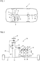
- Fig. 3 shows the torque couplings in the Fig. 2 Drive devices shown during operation of the switching device in the first switching state.
- the torque distribution on a rear axle of the motor vehicle when driving a left turn is shown as an example.
- an additional torque of the additional motor is to be used to influence the distribution of a driving torque coupled in via the ring gear 37 of the differential to the output shafts 17, 21.
- the arrow directions each show a direction in which torque is coupled.
- the torque coupled to the ring gear 37 is applied to the output shafts 21, 17 via the differential, and to the planet carrier via the second sun gear 23 33 of the second planetary gear 25 distributed.
- the transmission of the corresponding torque to the sun gear 34 of the third planetary gear 28 is not shown, since the planet carrier 36 of the third planetary gear 26, as to Fig. 2 explained, freewheeling in the first switching state and thus no torque transmission via the third planetary gear 26 takes place.
- a torque of 1500 Nm is provided as the drive torque
- a torque of 110 Nm can be provided by the additional motor 16, in particular via an additional transmission, not shown, and the torque distribution at the differential can take place in such a way that the planet carrier 19 engages the differential Torque of 151 Nm is transmitted to the left wheel, a torque of 1036 Nm is transmitted to the second output shaft 17 via the first sun gear 22 of the differential and an additional torque of 313 Nm is transmitted to the second output shaft 17 via the planet carrier 31, which means right wheel has a total torque of 1349 Nm.
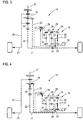
- Fig. 4 shows the drive device according to Fig. 2 , wherein the switching device is operated in the second switching state and a control device, not shown, controls the additional motor 16 such that at least the rear axle of the motor vehicle is driven exclusively by the additional motor 16.
- the ring gear 37 can be decoupled from a drive motor of the motor vehicle by means of a coupling device (not shown).
- FIG. 3 A comparison with Fig. 3 shows that the directions of the moment transfer in almost all cases with the in Fig. 3 shown situation match, but the direction of the torque transmission between the differential via the sun gear 23 to or from the second or third planetary gear 25, 26, however, compared to Fig. 3 turns. This is the case because torque transmission is not as in Fig. 3 shown from the planet carrier 33 to the common ring gear 32, but from the sun gear 34 to the common ring gear 32, with which the direction of rotation of the torque is reversed and with which a different transmission ratio is achieved.
- a torque of 360 Nm can be provided by the additional motor 16, in particular via a transmission ratio. Due to the torque clutch to the differential, which is different from the first switching state, a torque of 360 Nm is generated via the second sun gear 23 led to the differential and a torque of 739 Nm to the output shaft 17 via the planet carrier 31. The torque supplied to the output shaft 17 is distributed due to the additional torque coupling via the second sun gear 23 on the differential in such a way that 500 Nm via the wheel of the output shaft 17 assigned Motor vehicle can be transmitted to the road and react 239 Nm on the differential via the first sun gear 22.
- the second braking device has to brake a torque of 739 Nm.
- Fig. 5 shows the coupling of torques in a recuperation mode, in which the switching device is operated in the second switching state and in which the additional motor 16 is operated as a generator.
- both wheels are to be braked by recuperation with a torque of 72 Nm each.
- the torque of 72 Nm led to the differential via the second output shaft 21 is distributed almost uniformly to the second output shaft 17 and via the second sun gear 23 to the superposition gear 15.
- the first planetary gear 24 superimposes a torque of 68.7 Nm, which was guided from the differential via the second sun gear 23 and the third planetary gear 26 to the common ring gear 23, and a torque of 37.5 Nm that is coupled in from the auxiliary motor 16 via the sun gear 29 became a total torque of 106.4 Nm, which is guided via the planet carrier 31 to the output shaft 17.
- This torque is opposite to the torque supplied to the output shaft 17 via the first sun gear 22, which is why the output shaft 17 transmits the difference of the two torques of 72 Nm to the assigned wheel.
- recuperation mode the same torques are transmitted to both wheels.
- the drive device shown 14 the absorbed kinetic energy can be supplied to the auxiliary motor 16 for recuperation.
- Fig. 6 shows a further embodiment of a drive device 54, which is functionally the in Fig. 2 shown drive device 14 corresponds.
- the structure of the differential for distributing a drive torque to the output shafts 17, 21 and the branching of torques supplied by the superposition gear 15 via the sun gear 23 correspond to the structure of the drive device 14 in accordance with Fig. 2 ,
- the difference between the drive device 54 and the drive device 14 is that the guidance of the torques from the sun gear 23 to the second or third planetary gear 25, 26 and the braking of the shafts of the planetary gear 25, 26 is solved differently.
- the planet carrier 36 of the third planetary gear 26 and the sun gear 35 of the second planetary gear 25 are always fixed in a rotationally fixed manner, so that the second and the third planetary gear 25, 26 each work in two-shaft operation.
- the selection via which the planetary gear 25, 26 the torque tapped via the second sun gear 23 is guided to the common ring gear 32 is made by a clutch device 38 through which the second sun gear 23 of the differential in the first switching state with the planet carrier 33 of the second planetary gear 25 and in the second switching state with the sun gear 34 of the third planetary gear 26 is coupled.
- a coupling of torques is thus achieved in both switching states, which torque effectively corresponds to that in the drive device 14 Fig. 2 achieved coupling corresponds.
- the drive device 39 according to Fig. 7 corresponds to the structure of the superposition gear 15 of the in Fig. 2 shown drive device 14.
- a bevel gear differential 40 is used as a differential, via the housing 45 of which a drive torque can be coupled, which is distributed to the output shafts 17, 21.
- a further planetary gear 41 is provided as a torque-reducing transmission device.
- the housing of the bevel gear differential 40 is rigidly coupled to the ring gear 42 of the further planetary gear 41.
- the torque led to the superposition gear 15 is tapped via a sun gear 44.
- the planet carrier 43 is rigidly coupled to the output shaft 17.
- the housing 45 of the bevel gear differential 40 can also be rigidly coupled to the planet carrier 43 and the output shaft 17 to the ring gear. The same function is thus achieved with a different translation.
- Fig. 8 shows a further embodiment of a drive device 46, which is largely like that in FIG Fig. 7 shown drive device 39 is constructed.
- the differences from that in Fig. 7 Drive device 39 shown are that in the drive device 46 which are already closed Fig. 7 explained alternative coupling of the further planetary gear 41 to the bevel gear differential 40 and the output shaft 17 is used and that a different configuration is used for the third planetary gear 52.
- the third planetary gear 52 is designed as a planetary gear 52, in which the coupling between the ring gear 49 and the sun gear 50 takes place via two sets of planet gears, of which the planet gears 47, 48 are shown and which are carried by a common planet carrier 51.
- the torque is supplied from the differential to the third planetary gear 52 via the sun gear 50.
- the ring gear 49 is separate from the ring gear of the others Planetary gear 24, 25 formed and braked by the second braking device 28.
- a common ring gear of the planetary gears 24, 25 is coupled to the planet carrier 51 of the third planetary gear 52.
Description
Die Erfindung betrifft eine Antriebsvorrichtung für ein Kraftfahrzeug, mit einem Differential zur Verteilung eines über eine Antriebswelle zuführbaren Antriebsmoments auf zwei Abtriebswellen und einem mit dem Differential, einer der Abtriebswellen und einem Zusatzmotor gekoppelten Überlagerungsgetriebe zur Überlagerung von von der Abtriebswelle, dem Differential und dem Zusatzmotor zugeführten Drehmomenten, wobei das Differential über eine momentreduzierende Übersetzungseinrichtung mit dem Überlagerungsgetriebe gekoppelt ist.The invention relates to a drive device for a motor vehicle, having a differential for distributing a drive torque that can be supplied via an input shaft to two output shafts and a superimposition gearbox coupled to the differential, one of the output shafts and an additional motor for superimposing supply from the output shaft, the differential and the additional motor Torques, the differential being coupled to the superposition gear via a torque-reducing transmission device.
In Kraftfahrzeugen werden Differentiale genutzt, um ein durch einen Antriebsmotor bereitgestelltes Antriebsmoment auf verschiedene Räder einer Achse bzw. verschiedene Achsen zu verteilen. Um ein Durchdrehen von Rädern zu vermeiden und um in bestimmten Fahrsituationen gezielt Giermomente auf das Kraftfahrzeug zu übertragen ist es vorteilhaft, die Momentverteilung auf die Abtriebswellen eines solchen Differentials gezielt zu beeinflussen. Eine Möglichkeit hierfür ist das sogenannte elektronische Torque-Vectoring, bei dem ein Zusatzmotor genutzt wird, um die Verteilung der Drehmomente auf die Abtriebswellen des Differentials zu beeinflussen. Torque-Vectoring beschreibt in diesem Fall die Drehmomentenverteilung sowohl zum schneller drehenden als auch zum langsamer drehenden Rad einer Fahrzeugachse.Differentials are used in motor vehicles in order to distribute a drive torque provided by a drive motor to different wheels of one axle or different axles. In order to avoid wheel spinning and to transfer yaw moments to the motor vehicle in specific driving situations, it is advantageous to specifically influence the torque distribution on the output shafts of such a differential. One possibility for this is the so-called electronic torque vectoring, in which an additional motor is used to influence the distribution of the torques on the output shafts of the differential. In this case, torque vectoring describes the torque distribution for both the faster rotating and the slower rotating wheel of a vehicle axle.
Aus der Druckschrift
Eine weitere Möglichkeit ein elektrisches Torque-Vectoring-Getriebe auszubilden ist in der Druckschrift
Auch die Druckschrift
Um hohen Belastungen eines Überlagerungsgetriebes bei einem elektronischen Torque-Vectoring zu reduzieren, schlägt die Druckschrift
Daneben ist bekannt, einen im Rahmen des elektrischen Torque-Vectoring genutzten Elektromotor auch zur Bereitstellung von Hybrid-Funktionen in einem Kraftfahrzeug zu nutzen. So schlägt die Druckschrift
Die Druckschrift
Die Druckschrift
Der Erfindung liegt somit die Aufgabe zugrunde, eine Antriebsvorrichtung für ein Kraftfahrzeug anzugeben, die einerseits eine flexible Nutzung eines im Rahmen eines Torque-Vectoring genutzten Zusatzmotors und andererseits eine gegenüber dem Stand der Technik geringere Belastung eines Überlagerungsgetriebes während eines Torque-Vectorings möglich.The invention is therefore based on the object of specifying a drive device for a motor vehicle which, on the one hand, allows flexible use of an additional motor used in the context of torque vectoring and, on the other hand, a lower load on a superposition gear during torque vectoring compared to the prior art.
Die Aufgabe wird erfindungsgemäß durch eine Antriebsvorrichtung der eingangs genannten Art gelöst, wobei das Überlagerungsgetriebe eine durch eine Steuereinrichtung steuerbare Schalteinrichtung umfasst, wobei das Überlagerungsgetriebe in einem ersten Schaltzustand der Schalteinrichtung die von der Abtriebswelle, dem Differential und dem Zusatzmotor zugeführten Drehmomente derart überlagert, dass die Verteilung des Antriebsmoments auf die Abtriebswellen von einem durch den Zusatzmotor ausgeübten Zusatzdrehmoment abhängt, und in einem zweiten Schaltzustand der Schalteinrichtung die von der Abtriebswelle, dem Differential und dem Zusatzmotor zugeführten Drehmomente derart überlagert, dass das Zusatzdrehmoment gleichmäßig auf beide Abtriebswellen verteilt wird.The object is achieved according to the invention by a drive device of the type mentioned at the outset, the superposition gear comprising a switching device which can be controlled by a control device, the superposition gear being in a first switching state of the switching device the torques supplied by the output shaft, the differential and the additional motor are superimposed in such a way that the distribution of the drive torque to the output shafts depends on an additional torque exerted by the additional motor, and in a second switching state of the switching device that supplied by the output shaft, the differential and the additional motor Torques superimposed in such a way that the additional torque is evenly distributed over both output shafts.
Erfindungsgemäß wird somit vorgeschlagen eine Antriebsvorrichtung mit einem Differential und einem über eine momentreduzierende Übersetzungseinrichtung mit dem Differential gekoppelten Überlagerungsgetriebe, wie sie beispielsweise aus der Druckschrift
Gegenüber bekannten Antriebsvorrichtungen, die eine entsprechende Umschaltung einer Funktion eines Elektromotors ermöglichen, sieht die erfindungsgemäße Antriebsvorrichtung vorteilhaft vor, eine Schalteinrichtung zur Umschaltung zwischen den Nutzungen eines Zusatzmotors innerhalb eines Überlagerungsgetriebes vorzusehen, dem von dem Differential ein durch die Übersetzungseinrichtung reduziertes Drehmoment zugeführt ist. Durch eine derartige Ausbildung der Antriebsvorrichtung treten im Überlagerungsgetriebe geringere Drehmomente bzw. Kräfte auf, womit das Überlagerungsgetriebe entsprechend klein und leicht baubar ist. Da eine Umschaltung zwischen den Nutzungen des Zusatzmotors innerhalb des Überlagerungsgetriebes erfolgt, ist auch diese Umschaltung bei relativ geringen Drehmomenten bzw. Kräften möglich.Compared to known drive devices, which enable a corresponding switchover of a function of an electric motor, the drive device according to the invention advantageously provides a switching device for switching between the uses of an additional motor within a superimposition gearbox, to which a torque reduced by the transmission device is fed from the differential. Such a design of the drive device occurs in the superposition gear lower torques or forces, making the superimposed gearbox correspondingly small and easy to build. Since there is a switchover between the uses of the additional motor within the superimposition gearbox, this switchover is also possible with relatively low torques or forces.
Im zweiten Schaltzustand wird das Zusatzdrehmoment im Wesentlichen gleichmäßig auf beide Abtriebswellen verteilt. Aufgrund von Bauteiltoleranzen oder ähnlichem kann das Zusatzdrehmoment, das den einzelnen Abtriebswellen zugeführt wird, geringfügig voneinander abweichen. Die Verteilung des Zusatzdrehmoments auf die Abtriebswelle erfolgt vorzugsweise nach einer Skalierung des Zusatzdrehmoments durch eine oder mehrere Übersetzungsstufen.In the second switching state, the additional torque is distributed substantially evenly over both output shafts. Due to component tolerances or the like, the additional torque that is supplied to the individual output shafts may differ slightly from one another. The distribution of the additional torque to the output shaft preferably takes place after the additional torque has been scaled by one or more transmission stages.
Die Übersetzungen innerhalb der Antriebsvorrichtung sind vorteilhaft so gewählt, dass bei einer gleichen Drehzahl der Abtriebswellen der Zusatzmotor steht.The ratios within the drive device are advantageously chosen so that the auxiliary motor is at the same speed of the output shafts.
Das Überlagerungsgetriebe kann eine Überlagerungseinrichtung umfassen, die die von der Abtriebswelle und dem Zusatzmotor zugeführten Drehmomente mit einem aus dem von dem Differential zugeführten abgeleiteten Drehmoment überlagert, wobei das abgeleitete Drehmoment in dem ersten Schaltzustand einen ersten Drehsinn und in dem zweiten Schaltzustand einen dem ersten Drehsinn entgegengesetzten zweiten Drehsinn aufweist. Ein Schalten der Schalteinrichtung zwischen dem ersten und dem zweiten Schaltzustand ändert somit den Drehsinn des abgeleiteten Drehmoments. Ergänzend kann der Betrag des abgeleiteten Drehmoments je nach Schaltzustand unterschiedlich sein, beispielsweise wenn im ersten Schaltzustand und im zweiten Schaltzustand unterschiedliche Übersetzungen genutzt werden. Die Schalteinrichtung kann den Drehsinn des abgeleiteten Drehmoment selbst ändern oder weitere Komponenten des Überlagerungsgetriebes, insbesondere Kupplungen, Bremsen oder ähnliches, ansteuern, um den Drehsinn des abgeleiteten Drehmoments anzupassen.The superposition gear can comprise a superposition device which superimposes the torques supplied by the output shaft and the additional motor with a torque derived from the differential supplied, the derived torque in the first switching state a first direction of rotation and in the second switching state opposite the first direction of rotation has second sense of rotation. Switching the switching device between the first and the second switching state thus changes the direction of the derived torque. In addition, the amount of the derived torque can vary depending on the switching state, for example if different ratios are used in the first switching state and in the second switching state. The switching device can change the direction of rotation of the derived torque itself or control other components of the superposition gear, in particular clutches, brakes or the like, in order to adapt the direction of rotation of the derived torque.
Vorzugsweise umfasst das Überlagerungsgetriebe ein erstes, ein zweites und ein drittes Planetengetriebe, die jeweils ein Hohlrad, ein Sonnenrad und wenigstens ein an einem Planetenträger angeordnetes Planetenrad umfassen, wobei das erste Planetengetriebe die Überlagerungseinrichtung bildet, der das abgeleitete Drehmoment im ersten Schaltzustand über das zweite Planetengetriebe und im zweiten Schaltzustand über das dritte Planetengetriebe zugeführt ist. Planetengetriebe umfassen wenigstens drei "Wellen" bzw. Angriffspunkte für Drehmomente um eine Zentralachse. So können Drehmomente an dem Sonnenrad, an dem Hohlrad, das insbesondere das Gehäuse des Planetengetriebes bildet, und an dem Planetenträger eingekoppelt werden. Ein Planetengetriebe kann in einem Zweiwellenbetrieb genutzt werden, um Drehmomente mit einer vorgegebenen Übersetzung zu übertragen, wobei eine der Wellen drehfest angeordnet ist bzw. durch eine Kupplung, eine Bremse oder ähnliches drehfest gehalten wird. Sind alle Wellen beweglich, so arbeitet ein Planetengetriebe in einem Dreiwellenbetrieb als Überlagerungsgetriebe, wobei beispielsweise ein an einer Welle eingekoppeltes Drehmoment auf die beiden anderen Wellen verteilt werden kann oder über zwei Wellen eingekoppelte Drehmomente auf der dritten Welle überlagert werden.The superposition gear preferably comprises a first, a second and a third planetary gear, each of which comprises a ring gear, a sun gear and at least one planet gear arranged on a planet carrier, the first planetary gear forming the superimposition device which transmits the derived torque in the first switching state via the second planetary gear and is supplied in the second switching state via the third planetary gear. Planetary gears comprise at least three "shafts" or points of application for torques about a central axis. Torques can thus be coupled in on the sun gear, on the ring gear, which in particular forms the housing of the planetary gear, and on the planet carrier. A planetary gear can be used in a two-shaft operation to transmit torques with a predetermined transmission ratio, one of the shafts being arranged in a rotationally fixed manner or being held in a rotationally fixed manner by a clutch, a brake or the like. If all shafts are movable, a planetary gear works in a three-shaft operation as a superimposition gear, for example a torque coupled in on one shaft can be distributed to the other two shafts or torques coupled in via two shafts can be superimposed on the third shaft.
Die Schalteinrichtung kann derart ausgebildet sein, dass je nach Schaltzustand ein zweites oder ein drittes Planetengetriebe ausgewählt wird, über dass das abgeleitete Drehmoment dem ersten Planetengetriebe zugeführt wird. Durch eine Nutzung unterschiedlicher Kopplungen des zweiten und des dritten Planetengetriebe zu der Übersetzungseinrichtung und/oder zu dem ersten Planetengetriebe kann die Umkehrung des Drehsinns zwischen den Schaltzuständen erreicht werden.The switching device can be designed such that, depending on the switching state, a second or a third planetary gear is selected so that the derived torque is fed to the first planetary gear. By using different couplings of the second and third planetary gears to the translation device and / or to the first planetary gear, the reversal of the direction of rotation between the switching states can be achieved.
Vorteilhaft können das erste, das zweite und das dritte bzw. nur das zweite und das dritte Planetengetriebe baugleich ausgebildet sein, womit ein besonders effizienter Aufbau der erfindungsgemäßen Antriebsvorrichtung möglich ist, da gleich ausgebildete Bauteile für mehrere Funktionen nutzbar sind.The first, the second and the third or only the second and the third planetary gear can advantageously be constructed identically, which enables a particularly efficient construction of the drive device according to the invention, since components of the same design can be used for several functions.
Die Hohlräder des ersten, des zweiten und des dritten Planetengetriebes können als ein gemeinsames Hohlrad ausgebildet sein. Somit wird eine starre Kopplung zwischen den drei Hohlrädern erreicht. In diesem Fall kann die Zuführung des abgeleiteten Drehmoments von dem zweiten bzw. dem dritten Planetengetriebe zu dem ersten Planetengetriebe über das gemeinsame Hohlrad erfolgen.The ring gears of the first, second and third planetary gears can be designed as a common ring gear. A rigid coupling between the three ring gears is thus achieved. In this case, the derived torque can be supplied from the second or third planetary gear to the first planetary gear via the common ring gear.
Die Schalteinrichtung kann ausgebildet sein, in dem ersten Schaltzustand eine Rotation des Hohlrades, des Sonnenrades oder des Planetenträgers des zweiten Planetengetriebes zu blockieren und in dem zweiten Schaltzustand eine Rotation des Hohlrades, des Sonnenrades oder des Planetenträgers des dritten Planetengetriebes zu blockieren. Das jeweils blockierte Planetengetriebe arbeitet somit im Zweiwellenbetrieb und kann ein Drehmoment, das direkt oder indirekt von der Übersetzungseinrichtung zugeführt ist, mit einem definierten Drehsinn und einer definierten Übersetzung zwischen den beiden nicht blockierten Wellen übertragen. Vorteilhaft werden im ersten und im zweiten Schaltzustand unterschiedliche Arten von Wellen, also beispielsweise im ersten Schaltzustand das Sonnenrad des zweiten Planetengetriebes und im zweiten Schaltzustand der Planetenträger des dritten Planetengetriebes, blockiert. Dabei kann eine Welle, also das Sonnenrad, der Planetenträger oder das Hohlrad, des ersten Planetengetriebes sowohl mit einer Welle des zweiten Planetengetriebes als auch mit einer Welle des dritten Planetengetriebes gekoppelt sein. Über diese Welle kann dem ersten Planetengetriebe das abgeleitete Drehmoment zugeführt werden. Dies ist insbesondere durch ein gemeinsames Hohlrad des ersten, des zweiten und des dritten Planetengetriebes möglich.The switching device can be designed to block a rotation of the ring gear, the sun gear or the planet carrier of the second planetary gear in the first switching state and to block a rotation of the ring gear, the sun gear or the planet carrier of the third planetary gear in the second switching state. The respectively blocked planetary gear works in two-shaft operation and can transmit a torque that is supplied directly or indirectly from the transmission device with a defined sense of rotation and a defined transmission ratio between the two unblocked shafts. Different types of shafts are advantageously blocked in the first and second switching states, that is to say, for example, the sun gear of the second planetary gear in the first switching state and the planet carrier of the third planetary gear in the second switching state. A shaft, ie the sun gear, the planet carrier or the ring gear, of the first planetary gear can be coupled both to a shaft of the second planetary gear and to a shaft of the third planetary gear. The derived torque can be supplied to the first planetary gear via this shaft. This is possible in particular through a common ring gear of the first, the second and the third planetary gear.
Eine der Wellen des zweiten und des dritten Planetengetriebes ist je nach Schaltzustand jeweils blockiert oder läuft frei. Läuft diese eine Welle frei, so sind beliebige relative Drehungen der beiden anderen Wellen dieses Planetengetriebes möglich, womit durch das jeweilige Planetengetriebe keine Drehmomentübertragung zwischen diesen Wellen erfolgt. Ist diese Welle blockiert, so arbeitet das entsprechende Planetengetriebe im Zweiwellenbetrieb, womit eine definierte Kopplung mit einer vorgegebenen Übersetzung und einem vorgegebenen relativen Drehsinn zwischen den Drehmomenten an den anderen beiden Wellen erfolgt.Depending on the switching state, one of the shafts of the second and third planetary gears is blocked or runs free. If this one shaft runs free, any relative rotations of the other two shafts of this planetary gear are possible, which means that the respective planetary gear does not transmit any torque between these shafts. If this shaft is blocked, the corresponding planetary gear works in two-shaft operation, which means a defined coupling with a predefined ratio and a predetermined relative direction of rotation between the torques on the other two shafts.
Wird nun einer jeweils dritten Welle des zweiten und des dritten Planetengetriebes, die jeweils jene Welle ist, die weder mit einer Welle des ersten Planetengetriebes starr gekoppelt ist noch die Welle ist, die blockierbar ist bzw. frei läuft, das Drehmoment vom Differential über die Übersetzungseinrichtung zugeführt, so wird das zugeführte Drehmoment durch das zweite oder das dritte Planetengetriebe zu dem ersten Planetengetriebe übertragen, je nachdem, bei welchem der Planetengetriebe die blockierbare Welle blockiert ist. Bei entsprechender Zuordnung der Wellen, beispielsweise bei einer Blockierung eines Sonnenrads im ersten Schaltzustand und einer Blockierung eines Planetenträgers im zweiten Schaltzustand, ändert sich aufgrund des unterschiedlichen Momentübertragungsweges auch der Drehsinn des abgeleiteten Drehmoments zwischen den Schaltzuständen.If the third shaft of the second and third planetary gears is now the shaft that is neither rigidly coupled to a shaft of the first planetary gear nor is the shaft that is lockable or freely running, the torque from the differential via the transmission device supplied, the supplied torque is transmitted through the second or the third planetary gear to the first planetary gear, depending on the planetary gear in which the lockable shaft is blocked. With a corresponding assignment of the shafts, for example when a sun gear is blocked in the first switching state and a planet carrier is blocked in the second switching state, the direction of the derived torque also changes between the switching states due to the different torque transmission path.
Vorteilhaft umfasst die Schalteinrichtung eine erste Bremsvorrichtung zum Bremsen des Hohlrades, des Sonnenrades oder des Planetenträgers des zweiten Planetengetriebes und eine zweite Bremsvorrichtung zum Bremsen des Hohlrades, des Sonnenrades oder des Planetenträgers des dritten Planetengetriebes, wobei im ersten Schaltzustand die erste Bremseinrichtung und im ersten Schaltzustand die zweite Bremseinrichtung aktiv ist. Insbesondere kann als Bremseinrichtung eine Lamellenbremse genutzt werden. Durch ein Bremsen der entsprechenden Wellen ist eine Blockade besonders einfach bei geringer Geräuschentwicklung möglich. Alternativ oder ergänzend zum Bremsen der jeweiligen Welle könnte eine form- und/oder kraftschlüssige Kopplung, beispielsweise durch eine Klauenkupplung, erfolgen.The switching device advantageously comprises a first braking device for braking the ring gear, the sun gear or the planet carrier of the second planetary gear and a second braking device for braking the ring gear, the sun gear or the planet carrier of the third planetary gear, the first braking device and the first switching state in the first switching state second braking device is active. In particular, a multi-disc brake can be used as the braking device. By braking the corresponding shafts, a blockage is particularly easy with little noise. As an alternative or in addition to braking the respective shaft, a positive and / or non-positive coupling could take place, for example by means of a claw coupling.
In einer alternativen Ausführungsform können das Hohlrad, das Sonnenrad oder der Planetenträger des zweiten Planetengetriebes und das Hohlrad, das Sonnenrad oder der Planetenträger des dritten Planetengetriebes dauerhaft blockiert sein, wobei die Schalteinrichtung eine Kupplungseinrichtung umfasst, die das dem Überlagerungsgetriebe von dem Differential zugeführte Drehmoment in dem ersten Schaltzustand dem zweiten Planetengetriebe und in dem zweiten Schaltzustand dem dritten Planetengetriebe zuführt. In diesem Fall arbeiten das zweite und das dritte Planetengetriebe stets im Zweiwellenbetrieb, womit das Planetengetriebe, dem das über die momentreduzierende Übersetzungseinrichtung von dem Differential zugeführte Drehmoment zugeführt wird, dieses mit einer festen Übersetzung und mit einem vorgegebenen relativen Umlaufsinn an das erste Planetengetriebe überträgt. Jenes Planetengetriebe, dem dieses Drehmoment nicht zugeführt wird, weist eine freilaufende Welle auf, womit es lastfrei mitläuft. Die Kupplungseinrichtung kann eine Kupplungseinrichtung zur formschlüssigen und/oder zur kraftschlüssigen Kupplung sein. Insbesondere kann eine Klauenkupplung genutzt werden.In an alternative embodiment, the ring gear, the sun gear or the planet carrier of the second planetary gear and the ring gear, the sun gear or the planet carrier of the third planetary gear can be permanently blocked, wherein the switching device comprises a clutch device that in the superimposed gear from the differential torque supplied in the first switching state of the second planetary gear and supplies the third planetary gear in the second switching state. In this case, the second and third planetary gears always operate in two-shaft mode, with which the planetary gear, to which the torque supplied by the differential via the torque-reducing transmission device is fed, transmits it to the first planetary gear with a fixed ratio and with a predetermined relative sense of rotation. That planetary gear, to which this torque is not supplied, has a free-running shaft, with which it runs with no load. The coupling device can be a coupling device for positive and / or non-positive coupling. In particular, a dog clutch can be used.
Als das erste und/oder das zweite Planetengetriebe kann ein Planetengetriebe mit zwei Planetenradsätzen genutzt werden. Bei einem derartigen Planetengetriebe kann das Sonnenrad über zwei Planetenradsätze, die insbesondere in unterschiedlichen Abständen zu einer Zentralachse des Planetengetriebes an einem gemeinsamen Planetenträger angeordnet sind, mit dem Hohlrad gekoppelt sein. Derartige Planetengetriebe ermöglichen größere Unterschiede zwischen dem Hohlraddurchmesser und dem Sonnenraddurchmesser. Eine Wahl eines entsprechenden Planetengetriebes als das erste und/oder das zweite Planetengetriebe eröffnet weitere Möglichkeiten bei der Anpassung der relativen Übersetzungen in dem ersten und dem zweiten Schaltzustand.A planetary gear with two planetary gear sets can be used as the first and / or the second planetary gear. In such a planetary gear, the sun gear can be coupled to the ring gear via two planetary gear sets, which are arranged in particular at different distances from a central axis of the planetary gear on a common planet carrier. Such planetary gears allow major differences between the ring gear diameter and the sun gear diameter. Choosing a corresponding planetary gear as the first and / or the second planetary gear opens up further possibilities for adapting the relative gear ratios in the first and the second switching state.
Das Differential kann als doppeltes Planetengetriebe mit einem ersten und einem zweiten Planetenradsatz und einem ersten und einem zweiten Sonnenrad ausgebildet sein, wobei ein durch das Antriebsmoment antreibbares Hohlrad über das erste Sonnenrad und den ersten und den zweiten Planetenradsatz mit einer der Abtriebswellen und über den zweiten Planetenradsatz und das zweite Sonnenrad als momentreduzierendes Übersetzungselement mit dem Überlagerungsgetriebe gekoppelt ist. Das doppelte Planetengetriebe kann insbesondere als Ravigneaux-Satz ausgebildet sein. Das Vorsehen eines zweiten Sonnenrades stellt einen weiteren Momentabgriff für das Differential bereit, an dem ein reduziertes Drehmoment abgegriffen werden kann. Die Ausbildung der Übersetzungseinrichtung erfolgt also unter Mitbenutzung von Komponenten des Differentials, womit ein insgesamt einfacher Aufbau der erfindungsgemäßen Antriebsvorrichtung möglich ist.The differential can be designed as a double planetary gear with a first and a second planetary gear set and a first and a second sun gear, a ring gear drivable by the drive torque via the first sun gear and the first and the second planetary gear set with one of the output shafts and via the second planetary gear set and the second sun gear is coupled to the superposition gear as a torque-reducing transmission element. The double planetary gear can in particular be designed as a Ravigneaux set. The provision of a second sun gear provides a further torque tap for the differential, at which a reduced torque is tapped can. The translation device is thus designed with the use of components of the differential, with which an overall simple construction of the drive device according to the invention is possible.
Alternativ kann das Differential als ein Kegelraddifferential ausgebildet sein, wobei als momentreduzierende Übersetzungseinrichtung ein weiteres Planetengetriebe, das ein von einem Gehäuse des Kegelraddifferentials zugeführtes Drehmoment mit einem von einer der Abtriebswellen zugeführten Drehmoment zur Bereitstellung des dem Überlagerungsgetriebe zugeführten Drehmoments überlagert. Dabei sind verschiedene Zuordnungen der jeweiligen Drehmomente bzw. des Drehmomentabgriffs zu den Wellen des weiteren Planetengetriebes möglich.Alternatively, the differential can be designed as a bevel gear differential, a further planetary gear as a torque-reducing transmission device, which superimposes a torque supplied by a housing of the bevel gear differential with a torque supplied by one of the output shafts in order to provide the torque supplied to the superposition gear. Various assignments of the respective torques or of the torque tap to the shafts of the further planetary gear are possible.
Neben der erfindungsgemäßen Antriebsvorrichtung betrifft die Erfindung ein Kraftfahrzeug, das eine erfindungsgemäße Antriebsvorrichtung und einen Antriebsmotor zur Bereitstellung des Antriebsmoments umfasst. Der Antriebsmotor kann ein Verbrennungsmotor und der Zusatzmotor ein Elektromotor sein.In addition to the drive device according to the invention, the invention relates to a motor vehicle which comprises a drive device according to the invention and a drive motor for providing the drive torque. The drive motor can be an internal combustion engine and the additional motor can be an electric motor.
Ergänzend kann das Kraftfahrzeug eine Steuereinrichtung umfassen, die die Schalteinrichtung steuert. Diese kann ausgebildet sein, ein Laden eines Energiespeichers zu ermöglichen, der dem Zusatzmotor zugeordnet ist, indem zur Rekuperation, insbesondere bei einem Abbremsen des Kraftfahrzeugs, die Schalteinrichtung im zweiten Schaltzustand betrieben wird und der Zusatzmotor als Generator betrieben wird. In weiteren Betriebszuständen des Kraftfahrzeugs kann, insbesondere in Abhängigkeit von einer Geschwindigkeit, einem Giermoment und einem Lenkwinkel des Kraftfahrzeugs, zwischen einem Torque-Vectoring, wobei die Schalteinrichtung im ersten Schaltzustand betrieben wird, und einem Antrieb des Kraftfahrzeugs durch den Zusatzmotor bzw. einer Unterstützung des Antriebs durch den Zusatzmotor, wobei die Schalteinrichtung jeweils im zweiten Schaltzustand betrieben wird, gewechselt werden.In addition, the motor vehicle can include a control device that controls the switching device. This can be designed to enable charging of an energy store, which is assigned to the additional motor, in that for recuperation, in particular when the motor vehicle is braked, the switching device is operated in the second switching state and the additional motor is operated as a generator. In further operating states of the motor vehicle, in particular as a function of a speed, a yaw moment and a steering angle of the motor vehicle, torque vectoring, the switching device being operated in the first switching state, and a drive of the motor vehicle by the additional motor or a support of the Drive by the additional motor, with the switching device being operated in the second switching state.
Ergänzend betrifft die Erfindung ein Verfahren zum Betrieb eines Kraftfahrzeugs mit einem Antriebsmotor und einer Antriebsvorrichtung zum Antrieb der Räder wenigstens einer Achse des Kraftfahrzeugs, wobei die Antriebsvorrichtung ein Differential, durch das ein Antriebsmoment, das über eine Antriebswelle von dem Antriebsmotor zugeführt wird, auf zwei Abtriebswellen verteilt wird, und ein mit dem Differential, einer der Abtriebsachsen und einem Zusatzmotor gekoppeltes Überlagerungsgetriebe, durch das von der Abtriebsachse, dem Differential und dem Zusatzmotor zugeführte Drehmomente überlagert werden, umfasst, wobei das Differential über eine momentreduzierende Übersetzungseinrichtung mit dem Überlagerungsgetriebe gekoppelt ist, wobei das Überlagerungsgetriebe eine Schalteinrichtung umfasst, die durch eine Steuereinrichtung gesteuert wird, wobei durch das Überlagerungsgetriebe in einem ersten Schaltzustand der Schalteinrichtung die von der Abtriebsachse, dem Differential und dem Zusatzmotor zugeführten Drehmomente derart überlagert werden, dass die Verteilung des Antriebsmoments auf die Abtriebswellen von einem durch den Zusatzmotor ausgeübten Zusatzdrehmoment abhängt, und in einem zweiten Schaltzustand der Schalteinrichtung die von der Abtriebsachse, dem Differential und der Zusatzmaschine zugeführten Drehmomente derart überlagert werden, dass das Zusatzdrehmoment gleichmäßig auf beide Abtriebswellen verteilt wird.In addition, the invention relates to a method for operating a motor vehicle with a drive motor and a drive device for driving the wheels of at least one axle of the motor vehicle, the drive device being a differential, by means of which a drive torque, which is supplied via a drive shaft from the drive motor, to two output shafts is distributed, and a superimposed gearbox coupled to the differential, one of the output axles and an additional motor, by means of which torques supplied by the output axle, the differential and the additional motor are superimposed, the differential being coupled to the superimposed gearbox via a torque-reducing transmission device, wherein the superposition gear comprises a switching device which is controlled by a control device, the superposition gear in a first switching state of the switching device controlling the output axis, the differential and d Torques supplied to the additional motor are superimposed in such a way that the distribution of the drive torque to the output shafts depends on an additional torque exerted by the additional motor, and in a second switching state of the switching device the torques supplied by the output axis, the differential and the additional machine are superimposed in such a way that the Additional torque is evenly distributed on both output shafts.
Dabei kann in wenigstens einem Betriebsmodus der Steuereinrichtung die Schalteinrichtung in dem zweiten Schaltzustand betrieben werden, wobei der Zusatzmotor durch die Steuereinrichtung zur Bereitstellung eines Drehmoments zum Antrieb des Kraftfahrzeugs angesteuert wird. Dabei ist es möglich, das Kraftfahrzeug alleine durch das durch den Zusatzmotor bereitgestellte Zusatzmoment anzutreiben, es ist jedoch auch möglich, das Antriebsmoment des Antriebsmotors zu unterstützen, also eine "Boost"-Funktion zur Steigerung der Fahrleistung bereitzustellen. Dabei können durch den Zusatzmotor ausschließlich die Hinterräder des Kraftfahrzeugs angetrieben werden und durch den Antriebsmotor die Vorderräder. Alternativ ist es jedoch auch möglich, Antriebsmomente des Zusatzmotors und des Antriebsmotors auf der Hinterachse zu überlagern.In this case, the switching device can be operated in the second switching state in at least one operating mode of the control device, the auxiliary motor being controlled by the control device to provide a torque for driving the motor vehicle. It is possible to drive the motor vehicle solely by means of the additional torque provided by the additional motor, but it is also possible to support the drive torque of the drive motor, that is to say to provide a “boost” function for increasing the driving performance. Only the rear wheels of the motor vehicle can be driven by the additional motor and the front wheels by the drive motor. Alternatively, however, it is also possible to superimpose drive torques of the additional motor and the drive motor on the rear axle.
Als Zusatzmotor kann ein Elektromotor mit einer zugeordneten Energiespeichereinrichtung genutzt werden, wobei in wenigstens einem Betriebsmodus der Steuereinrichtung die Schalteinrichtung in dem zweiten Schaltzustand betrieben wird, wobei der Zusatzmotor als Generator zum Laden der Energiespeichereinrichtung betrieben wird. Es ist somit ein Rekuperationsbetrieb durch den Zusatzmotor möglich.An electric motor with an associated energy storage device can be used as the additional motor, the switching device being operated in the second switching state in at least one operating mode of the control device, the additional motor being operated as a generator for charging the energy storage device. Recuperation operation by the additional motor is thus possible.
Wie bereits erläutert ist bei einem Betrieb der Schalteinrichtung in dem ers-ten Schaltzustand eine Nutzung des Zusatzmotors zur Umverteilung von Drehmomenten auf die Abtriebswellen, also zum Torque-Vectoring, möglich.As already explained, when the switching device is operated in the first switching state, it is possible to use the additional motor to redistribute torques to the output shafts, that is to say for torque vectoring.
Das erfindungsgemäße Verfahren kann entsprechend der zur erfindungsgemäßen Abtriebsvorrichtung erläuterten Merkmale mit den dort genannten Vorteilen weitergebildet werden. Insbesondere ist es möglich, dass ein Überlagerungsgetriebe genutzt wird, das ein erstes, ein zweites und ein drittes Planetengetriebe umfasst, die die zur Antriebsvorrichtung erläuterten Funktionen aufweisen. Eine Anpassung des dem ersten Planetengetriebe zugeführten abgeleiteten Drehmoments ist insbesondere möglich, indem in dem ersten Schaltzustand durch die Schalteinrichtung eine Rotation des Hohlrades, des Sonnenrades oder des Planetenträgers des zweiten Planetengetriebes blockiert wird und in dem zweiten Schaltzustand eine Rotation des Hohlrades, des Sonnenrades oder des Planetenträgers des dritten Planetengetriebes blockiert wird. Das Blockieren kann jeweils insbesondere erfolgen, indem das jeweilige Hohlrad, Sonnenrad oder der jeweilige Planetenträger durch eine Bremsvorrichtung gebremst wird.The method according to the invention can be developed in accordance with the features explained for the output device according to the invention with the advantages mentioned there. In particular, it is possible that a superposition gear is used, which comprises a first, a second and a third planetary gear, which have the functions explained for the drive device. An adaptation of the derived torque supplied to the first planetary gear is possible, in particular, in that in the first switching state the rotation of the ring gear, the sun gear or the planet carrier of the second planetary gear is blocked by the switching device and in the second switching state a rotation of the ring gear, the sun gear or the Planet carrier of the third planetary gear is blocked. The blocking can take place in each case in particular by the respective ring gear, sun gear or the respective planet carrier being braked by a braking device.
Alternativ hierzu kann, wie zur erfindungsgemäßen Antriebsvorrichtung erläutert, eine Kupplungseinrichtung genutzt werden, durch die das dem Überlagerungsgetriebe vom Differential zugeführte Drehmoment in dem ersten Schaltzustand dem ersten Planetengetriebe über das zweite Planetengetriebe und in dem zweiten Schaltzustand über das dritte Planetengetriebe zugeführt wird.As an alternative to this, as explained for the drive device according to the invention, a clutch device can be used, by means of which the torque supplied to the superposition gear from the differential is supplied to the first planetary gear via the second planetary gear in the first switching state and via the third planetary gear in the second switching state.
Weitere Vorteile und Einzelheiten der Erfindung ergeben sich aus den folgenden Ausführungsbeispielen sowie den zugehörigen Zeichnungen. Dabei zeigen schematisch:
- Fig. 1
- ein Ausführungsbeispiel eines erfindungsgemäßen Kraftfahrzeugs,
- Fig. 2
- ein Ausführungsbeispiel einer erfindungsgemäßen Antriebsvorrichtung,
- Fig. 3, 4 und 5
- die Übertragungspfade und Richtungen von Drehmomenten in verschiedenen Betriebszuständen der in
Fig. 2 gezeigten Antriebsvorrichtung, und - Fig. 6 - 8
- weitere Ausführungsbeispiele erfindungsgemäßer Antriebsvorrichtungen.
- Fig. 1
- an embodiment of a motor vehicle according to the invention,
- Fig. 2
- an embodiment of a drive device according to the invention,
- 3, 4 and 5
- the transmission paths and directions of torques in different operating states of the in
Fig. 2 drive device shown, and - 6 - 8
- further embodiments of drive devices according to the invention.
Das Überlagerungsgetriebe 7 umfasst eine nicht dargestellte Schalteinrichtung, die beeinflusst, in welcher Art die dem Überlagerungsgetriebe zugeführten Drehmomente überlagert werden, und die durch die Steuereinrichtung 10 steuerbar ist. In einem ersten Schaltzustand werden die von der Abtriebswelle 6, von dem Differential 3 über die Übersetzungseinrichtung 9 und von dem Zusatzmotor 8 zugeführten Drehmomente derart überlagert, dass die Verteilung eines über die Antriebswelle 4 bereitgestellten Antriebsmoments auf die Abtriebswellen 5, 6 von einem durch den Zusatzmotor 8 ausgeübten Zusatzdrehmoment abhängt. Die Antriebsvorrichtung 2 dient somit als Torque-Vectoring-Einrichtung, die Drehmomente des Antriebsmotors auf die Räder verteilt. Der Zusatzmotor 8 ist durch die Steuereinrichtung 10 steuerbar, um die Momentverteilung zu beeinflussen.The
Im zweiten Schaltzustand der Schalteinrichtung erfolgt die Überlagerung der zugeführten Drehmomente derart, dass das durch den Zusatzmotor 8 bereitgestellte Zusatzdrehmoment, soweit im Rahmen von Bauteiltoleranzen möglich, gleichmäßig auf beide Abtriebswellen 5, 6 verteilt wird.In the second switching state of the switching device, the applied torques are superimposed in such a way that the additional torque provided by the
Beim Zusatzmotor 8 des Kraftfahrzeugs 1 handelt es sich um einen Elektromotor mit einem nicht gezeigten zugeordneten Energiespeicher. Durch eine Ansteuerung des Zusatzmotors 8 durch die Steuereinrichtung 10 zur Bereitstellung eines Zusatzdrehmoments können die Abtriebswellen 5, 6 im Kraftfahrzeug 1 ausschließlich durch das Zusatzdrehmoment oder durch eine Kombination eines durch den Antriebsmotor 53 bereitgestellten Drehmoments und des Zusatzdrehmoments angetrieben werden. Das durch den Zusatzmotor 8 bereitgestellte Zusatzdrehmoment wird im Rahmen der Zuführung des Zusatzdrehmoments zu den Abtriebswellen 5, 6 mehrfach übersetzt, so dass die Drehmomente an den Abtriebswellen 5, 6 eine Proportionalität zu dem durch den Zusatzmotor 8 bereitgestellten Zusatzdrehmoment aufweisen, die von dem entsprechenden Übersetzungsfaktor abhängt.The
Die Zusatzdrehmomente können durch den Zusatzmotor 8 auch derart bereitgestellt werden, dass sie einer Drehbewegung der Abtriebswellen 5, 6 entgegenwirken. Die Abtriebswellen 5, 6 werden gebremst. Insbesondere kann der Zusatzmotor 8 durch die Steuereinrichtung 10 als Generator betrieben werden, womit eine Rekuperation von Bewegungsenergie des Kraftfahrzeugs 1 möglich ist und der nicht gezeigte Energiespeicher geladen werden kann.The additional torques can also be provided by the
Bei dem Kraftfahrzeug 1 handelt sich um ein Kraftfahrzeug mit einem zu- und abschaltbaren Vierradantrieb. Ein vom Motor 53 bereitgestelltes Drehmoment bzw. eine Leistung des Motors wird zunächst über ein Getriebe 11 geführt, und anschließend über eines oder mehrere Differentiale 12 zwischen den Vorderrädern bzw. zwischen der Vorderachse und der Hinterachse verteilt. Das Differential 3 der Antriebsvorrichtung 2 ist von der von dem vorderen Differential 12 zur Antriebsvorrichtung 2 geführten Antriebswelle 2 über eine Kupplung 13 trennbar. Dies ist besonders vorteilhaft, wenn die Hinterräder des Kraftfahrzeugs 1 ausschließlich elektrisch durch den Zusatzmotor 8 betrieben werden sollen oder wenn an der Hinterachse ausschließlich eine Rekuperation von Bewegungsenergie erfolgen soll. Insbesondere kann ein Fahrbetrieb des Kraftfahrzeugs 1 derart erfolgen, dass die Antriebsvorrichtung 2 unter gewissen Bedingungen durch die Kupplung 13 von dem Antriebsmotor 53 entkoppelt ist, womit das Kraftfahrzeug zunächst ausschließlich durch einen Vorderradantrieb angetrieben wird. Ergänzend kann ein zusätzlicher Antrieb im zweiten Schaltzustand der Schalteinrichtung durch den Zusatzmotor 8 erfolgen, um die Fahrleistung des Kraftfahrzeugs 1 zu erhöhen, oder es kann durch den Zusatzmotor 8 im zweiten Schaltzustand Energie rekuperiert werden.
Das Überlagerungsgetriebe 15 ist über eine momentreduzierende Übersetzungseinrichtung, nämlich ein zweites Sonnenrad 23 des doppelten Planetengetriebes, mit dem Differential gekoppelt, um Drehmomente vom Differential an das Überlagerungsgetriebe bereitzustellen. Das doppelte Planetengetriebe mit seinen beiden Planetenradsätzen sowie dem ersten Sonnenrad 22 und dem zweiten Sonnenrad 23 ist als Ravigneaux-Satz ausgebildet, womit eine besonders kompakte Bauweise des Differentials und der momentreduzierenden Übertragungseinrichtung erreicht wird.The
Das Überlagerungsgetriebe 15 umfasst ein erstes, ein zweites und ein drittes Planetengetriebe 24, 25, 26 sowie eine erste und eine zweite Bremsvorrichtung 27, 28, über die jeweils eine Welle des zweiten und des dritten Planetengetriebes 25, 26 bremsbar ist. Die erste und die zweite Bremsvorrichtung 27, 28 bilden gemeinsam die Schalteinrichtung, wobei im ersten Schaltzustand die erste Bremsvorrichtung 27 aktiv ist, das heißt die entsprechende Welle bremst, und im zweiten Schaltzustand die zweite Bremsvorrichtung 28 aktiv ist. Die erste und zweite Bremsvorrichtung 27, 28 sind durch eine nicht gezeigte Steuereinrichtung steuerbar, um den Schaltzustand der Schalteinrichtung zu wählen.The
Das erste Planetengetriebe 24 bildet eine Überlagerungseinrichtung, die ein aus dem von dem Differential zugeführten Drehmoment abgeleitetes Drehmoment mit einem Drehmoment der Abtriebswelle 17 und einem Drehmoment des Zusatzmotors 16 überlagert. Hierzu treibt der Zusatzmotor 16 das Sonnenrad 29 des ersten Planetengetriebes 24 an und der Planetenträger 31 ist starr mit der Abtriebswelle 17 gekoppelt. Die Zuführung des abgeleiteten Drehmoments erfolgt über das Hohlrad, das als ein gemeinsames Hohlrad für das erste, das zweite und das dritte Planetengetriebe 24, 25, 26 ausgebildet ist. Je nach Schaltzustand der Schalteinrichtung wird dieses abgeleitete Drehmoment dem ersten Planetengetriebe 24 über das zweite Planetengetriebe 25 oder das dritte Planetengetriebe 26 zugeführt.The first
Das über das zweite Sonnenrad 23 aus dem Differential ausgekoppelte Drehmoment wird in das Überlagerungsgetriebe 15 einerseits über den Planetenträger 33 des zweiten Planetengetriebes 25 und andererseits über das Sonnenrad 34 des dritten Planetengetriebes 26 eingekoppelt. Ist die Schalteinrichtung im ersten Schaltzustand, so wird durch die erste Bremsvorrichtung 27 das Sonnenrad 35 des zweiten Planetengetriebes 25 gebremst bzw. blockiert, womit das zweite Planetengetriebe 25 in einem Zweiachsbetrieb betrieben wird, in dem das über den Planetenträger 33 eingekoppelte Drehmoment mit einer vorgegebenen Übersetzung und einem vorgegebenen relativen Drehsinn auf das gemeinsame Hohlrad 32 übertragen wird. Da im ersten Schaltzustand die zweite Bremsvorrichtung 28 nicht aktiv ist, ist der Planetenträger 36 des zweiten Planetengetriebes 26 im Wesentlichen frei drehbar, womit auch das Sonnenrad 34 im Wesentlichen kraftfrei gegenüber dem gemeinsamen Hohlrad 32 drehbar ist. Im ersten Schaltzustand wird ein Drehmoment somit vom zweiten Sonnenrad 23 über das zweite Planetengetriebe 25 auf das erste Planetengetriebe 24 übertragen.The torque decoupled from the differential via the
Im zweiten Schaltzustand ist die erste Bremsvorrichtung 27 nicht aktiv und die zweite Bremsvorrichtung 28 aktiv. Entsprechend ist der Planetenträger 36 des dritten Planetengetriebes 26 gebremst, womit das dritte Planetengetriebe 26 über das gemeinsame Hohlrad 33 das über das Sonnenrad 23 zugeführte Drehmoment an das erste Planetengetriebe 24 mit einer vorgegebenen Übersetzung und einem vorgegebenen relativen Drehsinn überträgt. Aufgrund der unterschiedlichen Führung des Drehmoments vom zweiten Sonnenrad 23 zum gemeinsamen Hohlrad 32 in den zwei Schaltzuständen unterscheidet sich das abgeleitete Drehmoment, das am gemeinsamen Hohlrad 32 wirkt, zwischen den Schaltzuständen sowohl betragsmäßig als auch im Vorzeichen. Der Drehsinn des am gemeinsamen Hohlrad 32 wirkenden Drehmoments ist zwischen dem ersten und dem zweiten Schaltzustand daher unterschiedlich.In the second switching state, the
Wie im Folgenden mit Bezug auf
Über das Differential wird das am Hohlrad 37 eingekoppelte Drehmoment auf die Abtriebswellen 21, 17 sowie über das zweite Sonnenrad 23 auf den Planetenträger 33 des zweiten Planetengetriebes 25 verteilt. Die Weiterführung des entsprechenden Drehmoments an das Sonnenrad 34 des dritten Planetengetriebes 28 ist nicht dargestellt, da der Planetenträger 36 des dritten Planetengetriebes 26, wie zu
Da das Sonnenrad 35 des zweiten Planetengetriebes 25 gebremst ist, wird das vom Differential über das zweite Sonnenrad 23 bereitgestellte Drehmoment über das gemeinsame Hohlrad 32 auf das erste Planetengetriebe 24 übertragen und dort mit dem vom Zusatzmotor 16 bereitgestellten Drehmoment überlagert. Dies führt zu einem insgesamt erhöhten Drehmoment an der zweiten Abtriebswelle 17, die das rechte Rad des Kraftfahrzeugs antreibt.Since the
Wird beispielsweise als Antriebsmoment ein Drehmoment von 1500 Nm bereitgestellt, so kann durch den Zusatzmotor 16, insbesondere über eine zusätzliche nicht gezeigte Übersetzung ein Drehmoment von 110 Nm bereitgestellt werden und die Momentverteilung am Differential kann derart erfolgen, dass über den Planetenträger 19 durch das Differential ein Drehmoment von 151 Nm zum linken Rad übertragen wird, über das erste Sonnenrad 22 des Differentials ein Drehmoment von 1036 Nm auf die zweite Abtriebswelle 17 übertragen wird und über den Planetenträger 31 ein zusätzliches Drehmoment von 313 Nm an die zweite Abtriebswelle 17 übertragen wird, womit am rechten Rad insgesamt ein Drehmoment von 1349 Nm bereitsteht.If, for example, a torque of 1500 Nm is provided as the drive torque, a torque of 110 Nm can be provided by the
Aufgrund der Nutzung einer momentreduzierenden Übersetzungseinrichtung, also der zusätzlichen Auskopplung über das zweite Sonnenrad 23 des Differentials, wird dem Überlagerungsgetriebe über das zweite Sonnenrad 23 im erläuterten Beispiel nur ein reduziertes Drehmoment von 313 Nm zugeführt. Die erste Bremseinrichtung 27 bremst hierbei ein Drehmoment von 110 Nm. Ein Torque-Vectoring ist mit der dargestellten Antriebsvorrichtung somit bereits bei relativ kleinen über das Überlagerungsgetriebe geführten Drehmomenten möglich, womit die Komponenten des Überlagerungsgetriebes besonders klein und leicht dimensioniert werden können.Due to the use of a torque-reducing transmission device, that is, the additional decoupling via the
Wie bereits zu
Ein Vergleich mit
Beispielsweise kann durch den Zusatzmotor 16, insbesondere über eine Übersetzung, ein Drehmoment von 360 Nm bereitgestellt werden. Aufgrund der zum ersten Schaltzustand unterschiedlichen Drehmomentkupplung zum Differential wird über das zweite Sonnenrad 23 ein Drehmoment von 360 Nm zum Differential geführt und über den Planetenträger 31 ein Drehmoment von 739 Nm an die Abtriebswelle 17. Das der Abtriebswelle 17 zugeführte Drehmoment verteilt sich aufgrund der zusätzlichen Momenteinkopplung über das zweite Sonnenrad 23 am Differential derart, dass 500 Nm über das der Abtriebswelle 17 zugeordnete Rad des Kraftfahrzeugs auf die Straße übertragen werden können und 239 Nm über das erste Sonnenrad 22 auf das Differential zurückwirken. Durch eine Überlagerung des über das erste Sonnenrad 22 von der Abtriebswelle 17 zum Differential geführten Drehmoments und des über das zweite Sonnenrad 23 zum Differential geführten Drehmoments wird über den gemeinsamen Planetenträger 20 auch für die Abtriebswelle 21 und somit für das linke Rad des Kraftfahrzeugs ein Drehmoment von 500 Nm bereitgestellt. Die zweite Bremseinrichtung muss im erläuterten Beispiel ein Drehmoment von 739 Nm bremsen.For example, a torque of 360 Nm can be provided by the
Das erste Planetengetriebe 24 überlagert ein Drehmoment von 68,7 Nm, das vom Differential über das zweite Sonnenrad 23 und das dritte Planetengetriebe 26 zum gemeinsamen Hohlrad 23 geführt wurde und ein Drehmoment von 37,5 Nm, dass vom Zusatzmotor 16 über das Sonnenrad 29 eingekoppelt wurde zu einem Gesamtdrehmoment von 106,4 Nm, das über den Planetenträger 31 zur Abtriebswelle 17 geführt wird. Dieses Drehmoment ist dem der Abtriebswelle 17 über das erste Sonnenrad 22 zugeführten Drehmoment entgegengesetzt, weshalb von der Abtriebswelle 17 die Differenz der beiden Drehmomente von 72 Nm auf das zugeordnete Rad übertragen wird. Im Rekuperationsbetrieb werden somit gleiche Drehmomente auf beide Räder übertragen. Durch die dargestellte Nutzung der Antriebsvorrichtung 14 kann die aufgenommene kinetische Energie dem Zusatzmotor 16 zur Rekuperation zugeführt werden.The first
Die Antriebsvorrichtung 39 gemäß
Durch die Nutzung des weiteren Planetengetriebes 41 als momentreduzierende Übertragungeinrichtung kann auch bei Nutzung eines Kegelradgetriebes eine Funktionalität erreicht werden, wie sie zu den vorangehenden Figuren erläutert wurde.By using the further
In Abhängigkeit der gewünschten Übersetzungsfaktoren ist es auch möglich, dass weitere Planetengetriebe 41, das die momentreduzierende Übertragungseinrichtung bildet, anders an das Kegelraddifferential 40, die Abtriebswelle 17 und das Überlagerungsgetriebe 15 anzubinden. Insbesondere kann das Gehäuse 45 des Kegelraddifferentials 40 auch starr mit dem Planetenträger 43 gekoppelt werden und die Abtriebswelle 17 mit dem Hohlrad. Es wird somit eine gleiche Funktion bei einer anderen Übersetzung erreicht.Depending on the desired transmission factors, it is also possible for other
Im gezeigten Ausführungsbeispiel folgt die Zuführung des Drehmoments vom Differential zum dritten Planetengetriebe 52 über das Sonnenrad 50. Das Hohlrad 49 ist im Planetengetriebe 52 separat von dem Hohlrad der weiteren Planetengetriebe 24, 25 ausgebildet und durch die zweite Bremsvorrichtung 28 bremsbar. Ein gemeinsames Hohlrad der Planetengetriebe 24, 25 ist mit dem Planetenträger 51 des dritten Planetengetriebes 52 gekoppelt.In the exemplary embodiment shown, the torque is supplied from the differential to the third
Durch die Antriebsvorrichtung 46 wird im Wesentlichen die gleiche Funktion erreicht wie durch die in den weiteren Figuren dargestellten Antriebsvorrichtungen, wobei durch Nutzung eines dritten Planetengetriebes 52 mit mehreren Planetenradsätzen eine flexiblere Anpassung der Übersetzungen möglich ist. Insbesondere kann ein großer Unterschied der Übersetzungen zwischen dem ersten und dem zweiten Schaltzustand und damit zwischen einer Boost- bzw. Rekuperationsfunktion und einem Torque-Vectoring erreicht werden.Essentially the same function is achieved by the
Claims (14)
- Drive unit for a motor vehicle, with a differential gear (3) for the distribution of a drive moment suppliable via a drive shaft (4) onto two output shafts (5, 6, 17, 21) and an superposition transmission (7, 15), coupled with the differential gear (3), one of the output shafts (6, 17) and an additional motor (8, 16), for superimposing torques supplied by the output shaft (6, 17), the differential gear (3) and the additional motor (8, 16), wherein the differential gear (3) is coupled via a moment-reducing transmission device (9) with the superposition transmission (7, 15), wherein the superposition transmission (7, 15) includes a switching apparatus controllable by a control device (10), wherein the superposition transmission (7, 15) in a first switching state of the switching apparatus superimposes the torques supplied by the output shaft (6, 17), the differential gear (3) and the additional motor (8, 16) such that the distribution of the drive moment onto the output shafts (5, 6, 17, 21) depends on an additional torque applied by the additional motor (8, 16),
characterised in
that the superposition transmission (7, 15) in a second switching state of the switching apparatus superimposes the torques supplied by the output shaft (6, 17), the differential gear (3) and the additional motor (8, 16) such that the additional torque is distributed equally onto both output shafts (5, 6, 17, 21). - Drive unit according to claim 1,
characterised in
that the superposition transmission (7, 15) includes a superposition device which superimposes the torques supplied by the output shaft (6, 17) and the additional motor (8, 16) with a torque derived from the torque supplied from the differential gear (3), wherein the derived torque in the first switching state has a first rotational direction and in the second switching state a second rotational direction opposite to the first rotational direction. - Drive unit according to claim 2,
characterised in
that the superposition transmission (7, 15) includes a first, a second and a third planetary gear (24, 25, 26, 52), which respectively include a hollow wheel (32), a sun wheel (29, 34, 35) and at least one planet wheel disposed on a planet carrier (31, 33, 36), wherein the first planetary gear (24) forms the superposition device, to which the derived torque is supplied in the first switching state via the second planetary gear (25) and in the second state via the third planetary gear (26, 52). - Drive unit according to claim 3,
characterised in
that the hollow wheels of the first, the second and the third planetary gear are formed as a shared hollow wheel (32). - Drive unit according to claim 3 or 4,
characterised in
that the switching device is configured in the first switching state to block a rotation of the hollow wheel (32), the sun wheel (35) or the planet carrier (33) of the second planetary gear (25) and in the second switching state to block a rotation of the hollow wheel (32, 49), the sun wheel (34) or the planet carrier (36) of the third planetary gear (26, 52). - Drive unit according to claim 5,
characterised in
that the switching device includes a first braking apparatus (27) for braking the hollow wheel (32), the sun wheel (35) or the planet carrier (33) of the second planetary gear (25) and a second braking apparatus (28) for braking the hollow wheel (32, 29), the sun wheel (34) or the planet carrier (36) of the third planetary gear (26, 52), wherein in the first switching state the first braking device (27) and in the second switching state of the second braking device (28) is active. - Drive unit according to claim 3 or 4,
characterised in
that the hollow wheel (32), the sun wheel (35) or the planet carrier (33) of the second planetary gear (25) and the hollow wheel (26, 52), the sun wheel (34) or the planet carrier (36) of the third planetary gear (26, 52) are permanently blocked, wherein the switching device includes a coupling apparatus (38) which supplies the torque supplied to the superposition transmission (7, 15) from the differential gear (3) in the first switching state to the second planetary gear (25) and in the second switching state to the third planetary gear (26, 52). - Drive unit according to any of claims 3 to 7,
characterised in
that a planetary gear (52) having two planetary gear sets is used as the first and/or the second planetary gear (24, 25, 26, 52). - Drive unit according to any of the preceding claims,
characterised in
that the differential gear (3) is in the form of a double planetary gear having a first and a second planetary gear set and a first and a second sun wheel (20, 22), wherein a hollow wheel (37) driveable by the drive moment is coupled via the first sun wheel (20) and the first and the second planetary gear set with one of the output shafts (17, 21) and via the second planetary gear set and the second wheel (22) as moment-reducing transmission apparatus with the superposition transmission (15). - Drive unit according to any of claims 1 to 8,
characterised in
that the differential gear (3) is in the form of a bevel-gear differential (40), wherein as moment-reducing transmission apparatus a further planetary gear (41), which superimposes a torque supplied from a housing (45) of the bevel-gear differential (40) with a torque supplied from one of the output shafts (17) for providing the torque supplied to the superposition transmission (15). - Motor vehicle,
characterised in
that it includes a drive unit (2, 14, 39, 46, 54) according to any of the preceding claims and a drive motor (53) for the provision of the drive moment. - Method for operating a motor vehicle having a drive motor and a drive unit for driving the wheels of at least one axle of the motor vehicle, wherein the drive unit includes a differential gear, by means of which a drive moment, which is supplied via a drive shaft from the drive motor, is distributed onto two output shafts, and a superposition transmission coupled with the differential gear, one of the drive shafts and an additional motor, by means of which the torques supplied by the drive shaft, the differential gear and the additional motor are superimposed, wherein the differential gear is coupled via a moment-reducing transmission device with the superposition transmission, wherein the superposition transmission includes a switching apparatus, which is controlled by a control device, wherein by means of the superposition transmission in a first switching state of the switching apparatus the torques supplied by the drive shaft, the differential gear and the additional motor are superimposed such that the distribution of the drive moment onto the output shafts depends on an additional torque exerted by the additional motor,
characterised in
that by means of the superposition transmission in a second switching state of the switching apparatus the torques supplied by the drive shaft, the differential gear and the additional machine are superimposed such that the additional torque is distributed equally onto both output shafts. - Method according to claim 12,
characterised in
that in at least one operating mode of the control device the switching device is operated in the second switching state, wherein the additional motor is controlled by the control device to provide a torque for driving the motor vehicle. - Method according to claim 12 or 13,
characterised in
that as an additional motor an electric motor having an assigned energy storage apparatus is used, wherein in at least one operating mode of the control device the switching device is operated in the second switching state, wherein the additional motor is operated as a generator for charging the energy storage apparatus.
Applications Claiming Priority (2)
| Application Number | Priority Date | Filing Date | Title |
|---|---|---|---|
| DE102014015793.8A DE102014015793A1 (en) | 2014-10-24 | 2014-10-24 | Drive device for a motor vehicle, motor vehicle and method for operating a motor vehicle |
| PCT/EP2015/002028 WO2016062384A1 (en) | 2014-10-24 | 2015-10-14 | Drive unit for a motor vehicle, motor vehicle, and method for operating a motor vehicle |
Publications (2)
| Publication Number | Publication Date |
|---|---|
| EP3209904A1 EP3209904A1 (en) | 2017-08-30 |
| EP3209904B1 true EP3209904B1 (en) | 2020-02-12 |
Family
ID=54325506
Family Applications (1)
| Application Number | Title | Priority Date | Filing Date |
|---|---|---|---|
| EP15781027.6A Active EP3209904B1 (en) | 2014-10-24 | 2015-10-14 | Drive unit for a motor vehicle, motor vehicle, and method for operating a motor vehicle |
Country Status (5)
| Country | Link |
|---|---|
| US (1) | US10400877B2 (en) |
| EP (1) | EP3209904B1 (en) |
| CN (1) | CN107466272B (en) |
| DE (1) | DE102014015793A1 (en) |
| WO (1) | WO2016062384A1 (en) |
Cited By (1)
| Publication number | Priority date | Publication date | Assignee | Title |
|---|---|---|---|---|
| DE102022000543A1 (en) | 2022-02-14 | 2023-08-17 | Mercedes-Benz Group AG | Method for switching an electric drive system of a motor vehicle |
Families Citing this family (19)
| Publication number | Priority date | Publication date | Assignee | Title |
|---|---|---|---|---|
| US10697528B2 (en) | 2016-03-23 | 2020-06-30 | Shaun Chu | Regenerative differential for differentially steered and front-wheel steered vehicles |
| US9709148B1 (en) * | 2016-04-20 | 2017-07-18 | Shaun Chu | Differential system with differential rate governed by variable speed motor and associated method of operation |
| CN107013654B (en) * | 2017-04-21 | 2023-04-07 | 吉林大学 | Electric differential mechanism with torque directional distribution function |
| DE102017214905B4 (en) * | 2017-08-25 | 2021-04-01 | Audi Ag | Method for operating a differential gear device for a motor vehicle |
| DE102017214917B4 (en) | 2017-08-25 | 2021-02-04 | Audi Ag | Motor vehicle transmission device for a motor vehicle with flexible integration of the electrical machine |
| JP6911652B2 (en) * | 2017-09-01 | 2021-07-28 | 三菱自動車工業株式会社 | Driving force adjustment device |
| EP3679276A4 (en) | 2017-09-08 | 2021-03-24 | Chu, Shaun | Differential system including stepped planetary gears with differential rate governed by variable speed motor and associated method of operation |
| DE102017220171B4 (en) * | 2017-11-13 | 2019-10-24 | Audi Ag | Drive device for a vehicle axle of a two-lane vehicle |
| DE102017220168B4 (en) | 2017-11-13 | 2019-12-12 | Audi Ag | Drive device for a vehicle axle of a two-lane vehicle |
| DE102017220167B3 (en) | 2017-11-13 | 2019-03-21 | Audi Ag | Drive device for a vehicle axle of a two-lane vehicle |
| DE102017220166B3 (en) | 2017-11-13 | 2019-03-14 | Audi Ag | Drive device for a vehicle axle of a two-lane vehicle |
| DE102017220165B4 (en) | 2017-11-13 | 2019-10-17 | Audi Ag | Drive device for a vehicle axle of a two-lane vehicle |
| DE102017220170B3 (en) * | 2017-11-13 | 2019-03-28 | Audi Ag | Drive device for a vehicle axle of a two-lane vehicle |
| US10801598B2 (en) * | 2018-11-07 | 2020-10-13 | Ford Global Technologies, Llc | Hybrid axle drive with torque vectoring |
| US10814721B2 (en) * | 2018-12-05 | 2020-10-27 | Hyundai Motor Company | Apparatus for torque vectoring |
| DE112018008201A5 (en) * | 2018-12-14 | 2021-09-30 | Gkn Automotive Limited | Gear arrangement for a hybrid drive |
| KR20210089816A (en) * | 2020-01-08 | 2021-07-19 | 현대자동차주식회사 | Device for torque vectoring |
| US11236804B2 (en) * | 2020-02-19 | 2022-02-01 | Dana Automotive Systems Group, Llc | Electric drive axle system with removable planetary gear assembly |
| WO2022093009A1 (en) * | 2020-11-02 | 2022-05-05 | Smesh Bv | Electric drive for a vehicle |
Family Cites Families (13)
| Publication number | Priority date | Publication date | Assignee | Title |
|---|---|---|---|---|
| JP2687052B2 (en) | 1991-04-19 | 1997-12-08 | 本田技研工業株式会社 | Torque distribution mechanism of differential gear |
| WO2006010186A1 (en) | 2004-07-26 | 2006-02-02 | Magna Steyr Fahrzeugtechnik Ag & Co Kg | Differential transmission unit with a controllable torque and speed distribution |
| DE102005049707A1 (en) | 2005-10-18 | 2007-04-26 | Zf Friedrichshafen Ag | Vehicle with a drive machine arranged in the vehicle transverse direction |
| DE102006031089A1 (en) | 2006-07-05 | 2008-01-17 | Fzgmbh | Motor vehicle`s drive device for driving axle, has overriding drive connected and formed in hybrid drive in shiftable manner, with which same power flow is transferred to wheels by drive machine and switched into drive moment distribution |
| DE102007017185B4 (en) | 2007-04-12 | 2008-12-18 | Fzgmbh | Transfer case for motor vehicles |
| WO2010151655A1 (en) | 2009-06-24 | 2010-12-29 | Fisker Automotive, Inc. | Drive configurations for high hybrid series/parallel high speed motor drive systems |
| DE102009056366A1 (en) * | 2009-11-30 | 2011-06-01 | Schaeffler Technologies Gmbh & Co. Kg | Drive system for a motor vehicle |
| DE102010036240A1 (en) | 2010-09-03 | 2012-03-08 | Schaeffler Technologies Gmbh & Co. Kg | Drive device has main drive, where differential mechanism is operatively connected to main drive via input member, and two output shafts are switched and are drivable together with electric machine via coupling transmission mechanism |
| DE102013202382B4 (en) | 2013-02-14 | 2016-06-23 | Schaeffler Technologies AG & Co. KG | Drive device for a vehicle and vehicle with the drive device |
| DE102013202381B4 (en) * | 2013-02-14 | 2016-06-23 | Schaeffler Technologies AG & Co. KG | Drive device for a vehicle and vehicle with the drive device |
| DE102013009081B4 (en) * | 2013-05-29 | 2018-09-13 | Audi Ag | Center differential gear arrangement for a drive device of a motor vehicle |
| CN103303116B (en) * | 2013-06-27 | 2018-03-30 | 中国北方车辆研究所 | Single power of motor shunting coupling speed change system |
| DE102014210549A1 (en) * | 2014-06-04 | 2015-12-17 | Schaeffler Technologies AG & Co. KG | Drive device for a vehicle |
-
2014
- 2014-10-24 DE DE102014015793.8A patent/DE102014015793A1/en not_active Withdrawn
-
2015
- 2015-10-14 WO PCT/EP2015/002028 patent/WO2016062384A1/en active Application Filing
- 2015-10-14 US US15/519,252 patent/US10400877B2/en active Active
- 2015-10-14 EP EP15781027.6A patent/EP3209904B1/en active Active
- 2015-10-14 CN CN201580057753.9A patent/CN107466272B/en active Active
Non-Patent Citations (1)
| Title |
|---|
| None * |
Cited By (1)
| Publication number | Priority date | Publication date | Assignee | Title |
|---|---|---|---|---|
| DE102022000543A1 (en) | 2022-02-14 | 2023-08-17 | Mercedes-Benz Group AG | Method for switching an electric drive system of a motor vehicle |
Also Published As
| Publication number | Publication date |
|---|---|
| DE102014015793A1 (en) | 2016-04-28 |
| EP3209904A1 (en) | 2017-08-30 |
| CN107466272B (en) | 2020-04-17 |
| WO2016062384A1 (en) | 2016-04-28 |
| US20170227105A1 (en) | 2017-08-10 |
| US10400877B2 (en) | 2019-09-03 |
| CN107466272A (en) | 2017-12-12 |
Similar Documents
| Publication | Publication Date | Title |
|---|---|---|
| EP3209904B1 (en) | Drive unit for a motor vehicle, motor vehicle, and method for operating a motor vehicle | |
| DE102013202381B4 (en) | Drive device for a vehicle and vehicle with the drive device | |
| DE102009049856B4 (en) | Gear arrangement for a vehicle and transmission with the gear assembly | |
| DE102013206176A1 (en) | vehicle drive | |
| WO2016096313A1 (en) | Gearing for a motor vehicle, and a drive train with same | |
| AT6549U1 (en) | DRIVE AXLE FOR A VEHICLE WITH VARIABLE TORQUE DISTRIBUTION | |
| DE102016224458A1 (en) | Motor vehicle transmission planetary gear sets with the same level translation | |
| DE102019107538A1 (en) | Torque vectoring transmission for a motor vehicle | |
| DE102015203197B3 (en) | Hybrid transmission for a vehicle and vehicle with the hybrid transmission | |
| WO2017207061A1 (en) | Electric drive arrangement, and drive train having an electric drive arrangement of this type | |
| EP3354504B1 (en) | Powertrain system | |
| DE102016221796B4 (en) | Hybrid transmission and hybrid powertrain | |
| DE102013222721A1 (en) | Drive train for a vehicle and vehicle with the drive train | |
| DE102016202725A1 (en) | Gear arrangement for a motor vehicle | |
| DE102015221190A1 (en) | Transmission device for a vehicle and vehicle with the transmission device | |
| DE102018215232A1 (en) | Transmission for a motor vehicle | |
| DE102012208678A1 (en) | Drive assembly for motor vehicle, has multi-stage transmission that have primary and secondary transmission input shaft and transmission output shaft, where input shaft has clutch for selectively coupling primary drive unit of vehicle | |
| DE102021205940A1 (en) | Transmission and drive train for a motor vehicle | |
| DE102021208545A1 (en) | Transmission for a vehicle and drive train with such a transmission | |
| DE102020007777A1 (en) | hybrid drive system | |
| EP3374221B1 (en) | Drive device for a motor vehicle | |
| DE102018215226A1 (en) | Transmission for a motor vehicle | |
| DE102021208567B3 (en) | Transmission and drive train for a vehicle | |
| DE102013219397A1 (en) | driving device | |
| EP3305571B1 (en) | Method for operating a hybrid drive device for a motor vehicle and corresponding hybrid drive device |
Legal Events
| Date | Code | Title | Description |
|---|---|---|---|
| STAA | Information on the status of an ep patent application or granted ep patent |
Free format text: STATUS: THE INTERNATIONAL PUBLICATION HAS BEEN MADE |
|
| PUAI | Public reference made under article 153(3) epc to a published international application that has entered the european phase |
Free format text: ORIGINAL CODE: 0009012 |
|
| STAA | Information on the status of an ep patent application or granted ep patent |
Free format text: STATUS: REQUEST FOR EXAMINATION WAS MADE |
|
| 17P | Request for examination filed |
Effective date: 20170524 |
|
| AK | Designated contracting states |
Kind code of ref document: A1 Designated state(s): AL AT BE BG CH CY CZ DE DK EE ES FI FR GB GR HR HU IE IS IT LI LT LU LV MC MK MT NL NO PL PT RO RS SE SI SK SM TR |
|
| AX | Request for extension of the european patent |
Extension state: BA ME |
|
| RIN1 | Information on inventor provided before grant (corrected) |
Inventor name: PINSCHMIDT, UDO Inventor name: SEIDE, STEFANIE |
|
| DAV | Request for validation of the european patent (deleted) | ||
| DAX | Request for extension of the european patent (deleted) | ||
| REG | Reference to a national code |
Ref country code: DE Ref legal event code: R079 Ref document number: 502015011722 Country of ref document: DE Free format text: PREVIOUS MAIN CLASS: F16H0048200000 Ipc: F16H0048360000 |
|
| GRAP | Despatch of communication of intention to grant a patent |
Free format text: ORIGINAL CODE: EPIDOSNIGR1 |
|
| STAA | Information on the status of an ep patent application or granted ep patent |
Free format text: STATUS: GRANT OF PATENT IS INTENDED |
|
| RIC1 | Information provided on ipc code assigned before grant |
Ipc: B60K 6/52 20071001ALI20190710BHEP Ipc: F16H 48/36 20120101AFI20190710BHEP Ipc: B60K 6/365 20071001ALI20190710BHEP Ipc: B60K 1/00 20060101ALI20190710BHEP Ipc: B60K 6/48 20071001ALI20190710BHEP |
|
| INTG | Intention to grant announced |
Effective date: 20190729 |
|
| GRAS | Grant fee paid |
Free format text: ORIGINAL CODE: EPIDOSNIGR3 |
|
| GRAA | (expected) grant |
Free format text: ORIGINAL CODE: 0009210 |
|
| STAA | Information on the status of an ep patent application or granted ep patent |
Free format text: STATUS: THE PATENT HAS BEEN GRANTED |
|
| AK | Designated contracting states |
Kind code of ref document: B1 Designated state(s): AL AT BE BG CH CY CZ DE DK EE ES FI FR GB GR HR HU IE IS IT LI LT LU LV MC MK MT NL NO PL PT RO RS SE SI SK SM TR |
|
| REG | Reference to a national code |
Ref country code: GB Ref legal event code: FG4D Free format text: NOT ENGLISH |
|
| REG | Reference to a national code |
Ref country code: CH Ref legal event code: EP |
|
| REG | Reference to a national code |
Ref country code: AT Ref legal event code: REF Ref document number: 1232521 Country of ref document: AT Kind code of ref document: T Effective date: 20200215 |
|
| REG | Reference to a national code |
Ref country code: IE Ref legal event code: FG4D Free format text: LANGUAGE OF EP DOCUMENT: GERMAN |
|
| REG | Reference to a national code |
Ref country code: DE Ref legal event code: R096 Ref document number: 502015011722 Country of ref document: DE |
|
| PG25 | Lapsed in a contracting state [announced via postgrant information from national office to epo] |
Ref country code: RS Free format text: LAPSE BECAUSE OF FAILURE TO SUBMIT A TRANSLATION OF THE DESCRIPTION OR TO PAY THE FEE WITHIN THE PRESCRIBED TIME-LIMIT Effective date: 20200212 Ref country code: NO Free format text: LAPSE BECAUSE OF FAILURE TO SUBMIT A TRANSLATION OF THE DESCRIPTION OR TO PAY THE FEE WITHIN THE PRESCRIBED TIME-LIMIT Effective date: 20200512 Ref country code: FI Free format text: LAPSE BECAUSE OF FAILURE TO SUBMIT A TRANSLATION OF THE DESCRIPTION OR TO PAY THE FEE WITHIN THE PRESCRIBED TIME-LIMIT Effective date: 20200212 |
|
| REG | Reference to a national code |
Ref country code: LT Ref legal event code: MG4D |
|
| REG | Reference to a national code |
Ref country code: NL Ref legal event code: MP Effective date: 20200212 |
|
| PG25 | Lapsed in a contracting state [announced via postgrant information from national office to epo] |
Ref country code: LV Free format text: LAPSE BECAUSE OF FAILURE TO SUBMIT A TRANSLATION OF THE DESCRIPTION OR TO PAY THE FEE WITHIN THE PRESCRIBED TIME-LIMIT Effective date: 20200212 Ref country code: SE Free format text: LAPSE BECAUSE OF FAILURE TO SUBMIT A TRANSLATION OF THE DESCRIPTION OR TO PAY THE FEE WITHIN THE PRESCRIBED TIME-LIMIT Effective date: 20200212 Ref country code: GR Free format text: LAPSE BECAUSE OF FAILURE TO SUBMIT A TRANSLATION OF THE DESCRIPTION OR TO PAY THE FEE WITHIN THE PRESCRIBED TIME-LIMIT Effective date: 20200513 Ref country code: BG Free format text: LAPSE BECAUSE OF FAILURE TO SUBMIT A TRANSLATION OF THE DESCRIPTION OR TO PAY THE FEE WITHIN THE PRESCRIBED TIME-LIMIT Effective date: 20200512 Ref country code: IS Free format text: LAPSE BECAUSE OF FAILURE TO SUBMIT A TRANSLATION OF THE DESCRIPTION OR TO PAY THE FEE WITHIN THE PRESCRIBED TIME-LIMIT Effective date: 20200612 Ref country code: HR Free format text: LAPSE BECAUSE OF FAILURE TO SUBMIT A TRANSLATION OF THE DESCRIPTION OR TO PAY THE FEE WITHIN THE PRESCRIBED TIME-LIMIT Effective date: 20200212 |
|
| PG25 | Lapsed in a contracting state [announced via postgrant information from national office to epo] |
Ref country code: NL Free format text: LAPSE BECAUSE OF FAILURE TO SUBMIT A TRANSLATION OF THE DESCRIPTION OR TO PAY THE FEE WITHIN THE PRESCRIBED TIME-LIMIT Effective date: 20200212 |
|
| PG25 | Lapsed in a contracting state [announced via postgrant information from national office to epo] |
Ref country code: SM Free format text: LAPSE BECAUSE OF FAILURE TO SUBMIT A TRANSLATION OF THE DESCRIPTION OR TO PAY THE FEE WITHIN THE PRESCRIBED TIME-LIMIT Effective date: 20200212 Ref country code: EE Free format text: LAPSE BECAUSE OF FAILURE TO SUBMIT A TRANSLATION OF THE DESCRIPTION OR TO PAY THE FEE WITHIN THE PRESCRIBED TIME-LIMIT Effective date: 20200212 Ref country code: DK Free format text: LAPSE BECAUSE OF FAILURE TO SUBMIT A TRANSLATION OF THE DESCRIPTION OR TO PAY THE FEE WITHIN THE PRESCRIBED TIME-LIMIT Effective date: 20200212 Ref country code: SK Free format text: LAPSE BECAUSE OF FAILURE TO SUBMIT A TRANSLATION OF THE DESCRIPTION OR TO PAY THE FEE WITHIN THE PRESCRIBED TIME-LIMIT Effective date: 20200212 Ref country code: PT Free format text: LAPSE BECAUSE OF FAILURE TO SUBMIT A TRANSLATION OF THE DESCRIPTION OR TO PAY THE FEE WITHIN THE PRESCRIBED TIME-LIMIT Effective date: 20200705 Ref country code: RO Free format text: LAPSE BECAUSE OF FAILURE TO SUBMIT A TRANSLATION OF THE DESCRIPTION OR TO PAY THE FEE WITHIN THE PRESCRIBED TIME-LIMIT Effective date: 20200212 Ref country code: LT Free format text: LAPSE BECAUSE OF FAILURE TO SUBMIT A TRANSLATION OF THE DESCRIPTION OR TO PAY THE FEE WITHIN THE PRESCRIBED TIME-LIMIT Effective date: 20200212 Ref country code: CZ Free format text: LAPSE BECAUSE OF FAILURE TO SUBMIT A TRANSLATION OF THE DESCRIPTION OR TO PAY THE FEE WITHIN THE PRESCRIBED TIME-LIMIT Effective date: 20200212 Ref country code: ES Free format text: LAPSE BECAUSE OF FAILURE TO SUBMIT A TRANSLATION OF THE DESCRIPTION OR TO PAY THE FEE WITHIN THE PRESCRIBED TIME-LIMIT Effective date: 20200212 |
|
| REG | Reference to a national code |
Ref country code: DE Ref legal event code: R097 Ref document number: 502015011722 Country of ref document: DE |
|
| PLBE | No opposition filed within time limit |
Free format text: ORIGINAL CODE: 0009261 |
|
| STAA | Information on the status of an ep patent application or granted ep patent |
Free format text: STATUS: NO OPPOSITION FILED WITHIN TIME LIMIT |
|
| 26N | No opposition filed |
Effective date: 20201113 |
|
| PG25 | Lapsed in a contracting state [announced via postgrant information from national office to epo] |
Ref country code: IT Free format text: LAPSE BECAUSE OF FAILURE TO SUBMIT A TRANSLATION OF THE DESCRIPTION OR TO PAY THE FEE WITHIN THE PRESCRIBED TIME-LIMIT Effective date: 20200212 |
|
| PG25 | Lapsed in a contracting state [announced via postgrant information from national office to epo] |
Ref country code: SI Free format text: LAPSE BECAUSE OF FAILURE TO SUBMIT A TRANSLATION OF THE DESCRIPTION OR TO PAY THE FEE WITHIN THE PRESCRIBED TIME-LIMIT Effective date: 20200212 Ref country code: PL Free format text: LAPSE BECAUSE OF FAILURE TO SUBMIT A TRANSLATION OF THE DESCRIPTION OR TO PAY THE FEE WITHIN THE PRESCRIBED TIME-LIMIT Effective date: 20200212 |
|
| REG | Reference to a national code |
Ref country code: CH Ref legal event code: PL |
|
| PG25 | Lapsed in a contracting state [announced via postgrant information from national office to epo] |
Ref country code: LU Free format text: LAPSE BECAUSE OF NON-PAYMENT OF DUE FEES Effective date: 20201014 Ref country code: MC Free format text: LAPSE BECAUSE OF FAILURE TO SUBMIT A TRANSLATION OF THE DESCRIPTION OR TO PAY THE FEE WITHIN THE PRESCRIBED TIME-LIMIT Effective date: 20200212 |
|
| REG | Reference to a national code |
Ref country code: BE Ref legal event code: MM Effective date: 20201031 |
|
| PG25 | Lapsed in a contracting state [announced via postgrant information from national office to epo] |
Ref country code: LI Free format text: LAPSE BECAUSE OF NON-PAYMENT OF DUE FEES Effective date: 20201031 Ref country code: BE Free format text: LAPSE BECAUSE OF NON-PAYMENT OF DUE FEES Effective date: 20201031 Ref country code: CH Free format text: LAPSE BECAUSE OF NON-PAYMENT OF DUE FEES Effective date: 20201031 |
|
| PG25 | Lapsed in a contracting state [announced via postgrant information from national office to epo] |
Ref country code: IE Free format text: LAPSE BECAUSE OF NON-PAYMENT OF DUE FEES Effective date: 20201014 |
|
| REG | Reference to a national code |
Ref country code: AT Ref legal event code: MM01 Ref document number: 1232521 Country of ref document: AT Kind code of ref document: T Effective date: 20201014 |
|
| PG25 | Lapsed in a contracting state [announced via postgrant information from national office to epo] |
Ref country code: AT Free format text: LAPSE BECAUSE OF NON-PAYMENT OF DUE FEES Effective date: 20201014 |
|
| PG25 | Lapsed in a contracting state [announced via postgrant information from national office to epo] |
Ref country code: TR Free format text: LAPSE BECAUSE OF FAILURE TO SUBMIT A TRANSLATION OF THE DESCRIPTION OR TO PAY THE FEE WITHIN THE PRESCRIBED TIME-LIMIT Effective date: 20200212 Ref country code: MT Free format text: LAPSE BECAUSE OF FAILURE TO SUBMIT A TRANSLATION OF THE DESCRIPTION OR TO PAY THE FEE WITHIN THE PRESCRIBED TIME-LIMIT Effective date: 20200212 Ref country code: CY Free format text: LAPSE BECAUSE OF FAILURE TO SUBMIT A TRANSLATION OF THE DESCRIPTION OR TO PAY THE FEE WITHIN THE PRESCRIBED TIME-LIMIT Effective date: 20200212 |
|
| PG25 | Lapsed in a contracting state [announced via postgrant information from national office to epo] |
Ref country code: MK Free format text: LAPSE BECAUSE OF FAILURE TO SUBMIT A TRANSLATION OF THE DESCRIPTION OR TO PAY THE FEE WITHIN THE PRESCRIBED TIME-LIMIT Effective date: 20200212 Ref country code: AL Free format text: LAPSE BECAUSE OF FAILURE TO SUBMIT A TRANSLATION OF THE DESCRIPTION OR TO PAY THE FEE WITHIN THE PRESCRIBED TIME-LIMIT Effective date: 20200212 |
|
| P01 | Opt-out of the competence of the unified patent court (upc) registered |
Effective date: 20230530 |
|
| PGFP | Annual fee paid to national office [announced via postgrant information from national office to epo] |
Ref country code: GB Payment date: 20231023 Year of fee payment: 9 |
|
| PGFP | Annual fee paid to national office [announced via postgrant information from national office to epo] |
Ref country code: FR Payment date: 20231024 Year of fee payment: 9 Ref country code: DE Payment date: 20231031 Year of fee payment: 9 |