EP3209223B1 - Dispositif pour la préparation d'une rotule pour la mise en place d'un implant rotulien - Google Patents
Dispositif pour la préparation d'une rotule pour la mise en place d'un implant rotulien Download PDFInfo
- Publication number
- EP3209223B1 EP3209223B1 EP15807945.9A EP15807945A EP3209223B1 EP 3209223 B1 EP3209223 B1 EP 3209223B1 EP 15807945 A EP15807945 A EP 15807945A EP 3209223 B1 EP3209223 B1 EP 3209223B1
- Authority
- EP
- European Patent Office
- Prior art keywords
- patella
- arm
- volumetric body
- height
- arms
- Prior art date
- Legal status (The legal status is an assumption and is not a legal conclusion. Google has not performed a legal analysis and makes no representation as to the accuracy of the status listed.)
- Not-in-force
Links
Images


Classifications
-
- A—HUMAN NECESSITIES
- A61—MEDICAL OR VETERINARY SCIENCE; HYGIENE
- A61B—DIAGNOSIS; SURGERY; IDENTIFICATION
- A61B17/00—Surgical instruments, devices or methods
- A61B17/14—Surgical saws
- A61B17/15—Guides therefor
- A61B17/154—Guides therefor for preparing bone for knee prosthesis
- A61B17/158—Cutting patella
-
- A—HUMAN NECESSITIES
- A61—MEDICAL OR VETERINARY SCIENCE; HYGIENE
- A61B—DIAGNOSIS; SURGERY; IDENTIFICATION
- A61B17/00—Surgical instruments, devices or methods
- A61B17/16—Instruments for performing osteoclasis; Drills or chisels for bones; Trepans
- A61B17/17—Guides or aligning means for drills, mills, pins or wires
- A61B17/1739—Guides or aligning means for drills, mills, pins or wires specially adapted for particular parts of the body
- A61B17/1764—Guides or aligning means for drills, mills, pins or wires specially adapted for particular parts of the body for the knee
- A61B17/1767—Guides or aligning means for drills, mills, pins or wires specially adapted for particular parts of the body for the knee for the patella
-
- A—HUMAN NECESSITIES
- A61—MEDICAL OR VETERINARY SCIENCE; HYGIENE
- A61B—DIAGNOSIS; SURGERY; IDENTIFICATION
- A61B17/00—Surgical instruments, devices or methods
- A61B17/56—Surgical instruments or methods for treatment of bones or joints; Devices specially adapted therefor
-
- A—HUMAN NECESSITIES
- A61—MEDICAL OR VETERINARY SCIENCE; HYGIENE
- A61B—DIAGNOSIS; SURGERY; IDENTIFICATION
- A61B17/00—Surgical instruments, devices or methods
- A61B17/56—Surgical instruments or methods for treatment of bones or joints; Devices specially adapted therefor
- A61B2017/568—Surgical instruments or methods for treatment of bones or joints; Devices specially adapted therefor produced with shape and dimensions specific for an individual patient
-
- A—HUMAN NECESSITIES
- A61—MEDICAL OR VETERINARY SCIENCE; HYGIENE
- A61B—DIAGNOSIS; SURGERY; IDENTIFICATION
- A61B90/00—Instruments, implements or accessories specially adapted for surgery or diagnosis and not covered by any of the groups A61B1/00 - A61B50/00, e.g. for luxation treatment or for protecting wound edges
- A61B90/03—Automatic limiting or abutting means, e.g. for safety
- A61B2090/033—Abutting means, stops, e.g. abutting on tissue or skin
- A61B2090/034—Abutting means, stops, e.g. abutting on tissue or skin abutting on parts of the device itself
Definitions
- the invention relates to the technical field of instruments, especially for orthopedic implants.
- the invention relates to a device for positioning and cutting a patella, and finds an advantageous application in knee arthroplasty, and more particularly the resurfacing of the patella.
- a knee prosthesis and more particularly the femoral implant that comprises this prosthesis, has, between the condylar pads, a trochlea on which is likely to slide, during the flexion of the lower limb, the kneecap.
- the practitioner In order to avoid pain, the practitioner must respect, during the establishment of the prosthetic implant patellar, the orientation of said implant relative to the trochlea, to avoid any phenomenon of projections.
- the thickness must also be respected, in order to avoid an inappropriate tension of the patellar ligament on the trochlea of the prosthetic implant likely to generate a limitation of the knee flexion.
- the preparation of the anatomical patella during the establishment of a patellar prosthetic implant is performed by means of a clip secured to a cutting guide.
- this clamp does not make it possible to prepare the patella for the specific pathological cases of patients to prosthesis.
- the object of the invention is to remedy these disadvantages in a simple, safe, effective and rational manner.
- the problem that the invention proposes to solve is to be able to prepare the anatomical patella by adapting, in particular, the positioning and the cutting height for the implementation of the patellar implant, in a manner personalized to the patella of the patient. , especially on the posterior side of the prosthesis patella.
- a device for the preparation of a patella for the implementation of a patellar implant comprising, in a known manner, a clip secured to a cutting guide. and having two branches hinged against an elastic return member.
- the device comprises a volumetric body designed to measure and acting as a spacer being shaped to be coupled to one of the branches, one of the faces of the body, considered opposite to the coupling with the branch, has a recessed hollow recess, in inverted form, the anterior face of the patella positioned on the other branch, said cavity and the height of the volumetric body being defined by a scanner or MRI data shape modeling software of said patella, to give the orientation and positioning of the prosthetic patella, the posterior cutting height and the drilling depth of a fixation stud of the patellar implant, the volumetric body acting as spacer is pierced coaxially with a hole of diameter substantially equal to that of the fixation stud of the patellar implant.
- the hole of the volumetric body is extended by a centering stud adapted to cooperate with a complementary shape that presents one branches of the clamp, in particular the upper branch, said body having a flat bearing surface cooperating with said branch.
- the branch which is coupled to the volumetric body, serves as a stop to a bit engaged in the hole of the volumetric body.
- Said stop corresponds to the drilling depth of the patella taking into account the adapted height of said body.
- the two branches of the device each receive at their free end, an articulated arm, said arms receiving the volumetric body and being mounted with capacity for moving height to be spaced apart or brought closer to one another, in a parallel manner, in combination with a guide column receiving the return member.
- the end of the relative arm at the lower branch has anchoring asperities cooperating with the patella.
- the cutting guide of the device is mounted with height adjustment capability on the guide column.
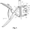
- the device for the production of a ball joint, comprises a clamp generally designated by (P) and having two branches (1) and (2) hinged against an elastic member reminder (3), especially in the form of a spring.
- This clamp (P) is, moreover, subject to a cutting guide (4).
- the clamp comprises a volumetric body (5), custom-designed, of parallelepipedal general shape, and acting as a spacer.
- the spacer (5) is intended to be temporarily coupled to one of the branches on the clamp, in particular the upper branch (2), as will be indicated later.
- one of the faces (5a) of the body (5) seen opposite the coupling face with the branch (2), has a hollow recess, matching, in inverted form, the anterior surface of the anatomical patella of the patient positioned on the other limb (1).
- This intaglio imprint and the height of the volumetric body (5) are defined by a shape modeling software scanner or MRI data of the anatomical patella.
- the two branches (1) and (2) each receive at their free ends an articulated arm (6) and (7).
- the arms (6) and (7) are mounted with height displacement capability to be spaced apart or brought closer to each other, in parallel, in combination with a guide column (8) under the effect of the actuation of the branches (1) and (2) of the clamp.
- the guide column (8) receives the return spring (3) mounted between the two arms (6) and (7).
- the volumetric body (5) is pierced coaxially with a through hole whose diameter substantially corresponds to that of the fixing stud of the prosthetic implant patellar.
- This hole is extended by a centering stud (5b) adapted to cooperate with a complementary outlet recess (7a) that has a circular bearing surface (7b) formed at the free end of the arm (7) of the upper branch (2). .
- a flat bearing face (5c) of the spacer (5) cooperates with said bearing surface (7b).
- the arm (7) which is coupled to the volumetric body (5), serves as a stop for a bit (9) engaged in the aligned holes of the cavity (7a) of the bearing surface (7b), the pad (5b) and the body (5).
- the body of the wick (9) has a stop (9a) adapted to bear on the upper face of the arm (7) at the face (7c) of the circular bearing (7b).
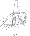
- the free end of the lower arm (6) has anchoring asperities cooperating with the anatomical patella, as shown in FIG. figure 2 .
- the spacer (5) with respect to the bearing surface which marries in inverted form the inner face of the anatomical patella, which shape is defined by a shape modeling software scanner or MRI data that the practitioner has asked his patient, allows to define the positioning and orientation of the clamp with the posterior articular surface of the patella.
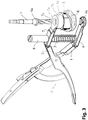
- the figure 3 shows the preparation of the ball (R) positioned relative to the volumetric body (5), before drilling the hole in the patellar block, with the bit (9), positioned in the orifice (7a) and abutting by its bearing ( 9a) on the face (7c) of the arm (7).
- This stop determines, thanks to the adapted height of the volumetric form (5), the good drilling depth of the anatomical patella.
- the figure 4 shows the preparation of the anatomical patella (R) attached to the spacer (5), before placing the cutting guide (4) on the column (8) and the figure 5 , the cutting block (4) is placed on the column (8) and is locked in the lower position on the upper face of the arm (7), for example by means of a wheel.
- the cutting guide (4) is positioned at the correct cutting height considering the correct height of the volumetric body (5), which height is made to measure, following scanner or MRI data, thus allowing the cutting of the articular face.
- posterior of the anatomical patella by means of, for example, a saw blade inserted in a slot (4a), that has the cutting guide (4).
- the prosthetic patella is, therefore, in the desired orientation.
Landscapes
- Health & Medical Sciences (AREA)
- Surgery (AREA)
- Life Sciences & Earth Sciences (AREA)
- Medical Informatics (AREA)
- Animal Behavior & Ethology (AREA)
- Orthopedic Medicine & Surgery (AREA)
- Oral & Maxillofacial Surgery (AREA)
- Engineering & Computer Science (AREA)
- Biomedical Technology (AREA)
- Heart & Thoracic Surgery (AREA)
- Dentistry (AREA)
- Molecular Biology (AREA)
- Nuclear Medicine, Radiotherapy & Molecular Imaging (AREA)
- General Health & Medical Sciences (AREA)
- Public Health (AREA)
- Veterinary Medicine (AREA)
- Physical Education & Sports Medicine (AREA)
- Transplantation (AREA)
- Surgical Instruments (AREA)
- Prostheses (AREA)
Description
- L'invention se rattache au secteur technique des instruments, notamment pour implants orthopédiques.
- Plus particulièrement, l'invention concerne un dispositif de positionnement et de coupe personnalisée d'une rotule, et trouve une application avantageuse dans l'arthroplastie de genou, et plus particulièrement le resurfaçage de la rotule.
- De manière parfaitement connu par un homme du métier, une prothèse de genou, et plus particulièrement l'implant fémoral que comprend cette prothèse présente, entre des patins condyliens, une trochlée sur laquelle est susceptible de glisser, lors de la flexion du membre inférieur, la rotule. Afin d'éviter les douleurs, le praticien doit respecter, lors de la mise en place de l'implant prothétique rotulien, l'orientation dudit implant par rapport à la trochlée, afin d'éviter tous phénomènes de ressauts. Il convient également de respecter l'épaisseur, afin d'éviter une tension inappropriée du ligament rotulien sur la trochlée de l'implant prothétique susceptible de générer une limitation de la flexion de genou.
- Généralement, la préparation de la rotule anatomique lors de la mise en place d'un implant prothétique rotulien, s'effectue au moyen d'une pince assujettie à un guide de coupe. Toutefois, la conception de cette pince ne permet pas de préparer la rotule aux cas pathologiques spécifiques des patients à prothéser.
-
US 5 342 364 A décrit un dispositif conforme au préambule de la revendication 1. - L'invention s'est fixée pour but de remédier à ces inconvénients d'une manière simple, sûre, efficace et rationnelle.
- Le problème que se propose de résoudre l'invention est de pouvoir préparer la rotule anatomique en adaptant, notamment, le positionnement et la hauteur de coupe pour la mise en place de l'implant rotulien, d'une manière personnalisée à la rotule du patient, notamment à la face postérieure de la rotule à prothéser.
- Pour résoudre un tel problème, il a été conçu et mis au point un dispositif pour la préparation d'une rotule pour la mise en place d'un implant rotulien, comprenant, d'une manière connue, une pince assujettie à un guide de coupe et comportant deux branches articulées à l'encontre d'un organe élastique de rappel.
- Selon l'invention, le dispositif comprend un corps volumétrique conçu sur mesure et faisant office d'espaceur en étant conformé pour être accouplé à l'une des branches, l'une des faces du corps, considérée à l'opposé de l'accouplement avec la branche, présente une empreinte en creux épousant, en forme inversée, la face antérieure de la rotule positionnée sur l'autre branche, ladite empreinte et la hauteur du corps volumétrique étant définies par un logiciel de modélisation de forme de données scanner ou IRM de ladite rotule, afin de donner l'orientation et le positionnement de la rotule prothétique, la hauteur de coupe postérieure et la profondeur de perçage d'un plot de fixation de l'implant rotulien, le corps volumétrique faisant office d'espaceur est percé coaxialement d'un trou de diamètre sensiblement égal à celui du plot de fixation de l'implant rotulien.
- Ces caractéristiques permettent de donner l'orientation et le positionnement de la rotule prothétique, la hauteur de coupe postérieure et la profondeur de perçage du plot de fixation de l'implant prothétique rotulien.
- Pour résoudre le problème poser d'accoupler le corps volumétrique à l'une des branches de la pince, notamment la branche supérieure, le trou du corps volumétrique est prolongé par un plot de centrage apte à coopérer avec une forme complémentaire que présente l'une des branches de la pince, notamment la branche supérieure, ledit corps présentant une surface d'appui plane coopérant avec ladite branche.
- Pour résoudre le problème posé de déterminer la bonne profondeur de perçage de la rotule anatomique, la branche, où est accouplé le corps volumétrique, fait office de butée à une mèche engagée dans le trou du corps volumétrique. Ladite butée correspond à la profondeur de perçage de la rotule compte tenu de la hauteur adaptée dudit corps.
- Dans une forme de réalisation, les deux branches du dispositif reçoivent chacune à leur extrémité libre, un bras articulé, lesdits bras recevant le corps volumétrique et étant montés avec capacité de déplacement en hauteur pour être écartés ou rapprochés l'un de l'autre, d'une manière parallèle, en combinaison avec une colonne de guidage recevant l'organe de rappel.
- Pour résoudre le problème posé de positionner la rotule anatomique sur l'une des branches de la pince en vue du positionnement du corps volumétrique pour la préparation de ladite rotule, l'extrémité du bras relatif à la branche inférieure, présente des aspérités d'ancrage coopérant avec la rotule.
- Pour résoudre le problème posé de réaliser la découpe de la face antérieure de la rotule, le guide de coupe du dispositif est monté avec capacité de réglage en hauteur sur la colonne de guidage.
- L'invention est exposée ci-après plus en détails à l'aide des figures des dessins annexés dans lesquels :
- la
figure 1 est une vue en perspective du dispositif, avant mise en place de l'espaceur par rapport à la rotule anatomique, - la
figure 2 montre le dispositif pour la préparation de la rotule positionnée en relation avec l'espaceur, après serrage des branches de la pince, - la
figure 3 montre le dispositif avant perçage de l'empreinte du plot rotulien avec une mèche, - la
figure 4 est une vue en perspective du dispositif, avant mise en place du guide de coupe, - la
figure 5 est une vue en perspective du dispositif, en position serrée des branches avec l'espaceur et la rotule anatomique, le guide de coupe étant bloqué en position basse sur la face de la branche supérieure, et déterminé par la bonne hauteur de l'espaceur afin d'assurer la découpe de la face antérieure de la rotule anatomique, moyennant un organe de coupe, tel qu'une scie. - Le dispositif, selon l'invention, pour l'élaboration d'une rotule, comprend une pince désignée dans son ensemble par (P) et présentant deux branches (1) et (2), articulées à l'encontre d'un organe élastique de rappel (3), notamment sous forme d'un ressort. Cette pince (P) est, par ailleurs, assujettie à un guide de coupe (4).
- Selon une caractéristique de l'invention, la pince comprend un corps volumétrique (5), conçu sur mesure, de forme générale parallépipédique, et faisant office d'espaceur. L'espaceur (5) est destiné à être temporairement accouplé à l'une des branches sur la pince, notamment la branche supérieure (2), comme il sera indiqué ultérieurement.
- D'une manière importante, l'une des faces (5a) du corps (5), considérée à l'opposé de la face d'accouplement avec la branche (2), présente une empreinte en creux, épousant, en forme inversée, la face antérieure de la rotule anatomique du patient positionnée sur l'autre branche (1). Cette empreinte en creux et la hauteur du corps volumétrique (5) sont définis par un logiciel de de modélisation de forme des données scanner ou IRM de la rotule anatomique. Ces dispositions permettent de donner l'orientation et le positionnement de la rotule prothétique, la hauteur de coupe postérieure, la profondeur de perçage du plot de fixation que présente l'implant rotulien.
- Dans la forme de réalisation illustrée, les deux branches (1) et (2) reçoivent chacune à leurs extrémités libres un bras articulé (6) et (7). Les bras (6) et (7) sont montés avec capacité de déplacement en hauteur pour être écartés ou rapprocher l'un de l'autre, de manière parallèle, en combinaison avec une colonne de guidage (8) sous l'effet de l'actionnement des branches (1) et (2) de la pince. La colonne de guidage (8) reçoit le ressort de rappel (3) monté entre les deux bras (6) et (7).
- Le corps volumétrique (5) est percé coaxialement d'un trou débouchant dont le diamètre correspond sensiblement à celui du plot de fixation de l'implant prothétique rotulien. Ce trou est prolongé par un plot de centrage (5b) apte à coopérer avec une empreinte complémentaire débouchante (7a) que présente une portée circulaire (7b), formée à l'extrémité libre du bras (7) de la branche supérieure (2). Après engagement du plot (5b) dans l'empreinte (7a) de la portée (7b), une face d'appui plane (5c) de l'espaceur (5), coopère avec ladite portée (7b).
- Le bras (7), où est accouplé le corps volumétrique (5), fait office de butée à une mèche (9) engagée dans les trous alignés de l'empreinte (7a) de la portée (7b), du plot (5b) et du corps (5). Dans l'exemple illustré, comme le montre la
figure 3 , le corps de la mèche (9) présente une butée (9a) apte à prendre appui sur la face supérieure du bras (7) au niveau de la face (7c) de la portée circulaire (7b). - L'extrémité libre du bras inférieur (6) présente des aspérités d'ancrage coopérant avec la rotule anatomique, comme le montre la
figure 2 . - Il ressort de ces caractéristiques que l'espaceur (5), eu égard à la surface d'appui qui épouse en forme inversée la face intérieure de la rotule anatomique, laquelle forme est définie par un logiciel de modélisation de forme des données scanner ou IRM que le praticien aura demandé à son patient, permet de définir le positionnement et l'orientation de la pince avec la face articulaire postérieure de la rotule.
- Comme indiqué, la
figure 3 montre la préparation de la rotule (R) positionnée par rapport au corps volumétrique (5), avant en perçage du trou au plot rotulien, avec la mèche (9), positionnée dans l'orifice (7a) et en butée par sa portée (9a) sur la face (7c) du bras (7). Cette butée détermine, grâce à la hauteur adaptée de la forme volumétrique (5), la bonne profondeur de perçage de la rotule anatomique. - La
figure 4 montre la préparation de la rotule anatomique (R) assujettie à l'espaceur (5), avant mise en place du guide de coupe (4) sur la colonne (8) et lafigure 5 , le bloc de coupe (4) est mis en place sur la colonne (8) et est bloqué en position basse sur la face supérieure du bras (7), par exemple au moyen d'une molette. Le guide de coupe (4) est positionné à la bonne hauteur de coupe en considérant la bonne hauteur du corps volumétrique (5), laquelle hauteur est réalisée sur mesure, suite aux données scanner ou IRM, permettant par conséquent la découpe de la face articulaire postérieure de la rotule anatomique au moyen, par exemple, d'une lame de scie insérée dans une fente (4a), que présente le guide de coupe (4). La rotule prothétique se trouve, par conséquent, dans l'orientation souhaitée. - Les avantages ressortent bien de la description.
Claims (6)
- Dispositif pour la préparation d'une rotule pour la mise en place d'un implant rotulien, comprenant une pince assujettie à un guide de coupe (4) et comportant deux branches articulées (1) et (2) à l'encontre d'un organe élastique de rappel (3), le dispositif comprenant un corps volumétrique (5) faisant office d'espaceur et conformé pour être accouplé à l'une des branches (2), l'une des faces du corps (5) considérée à l'opposé de l'accouplement avec la branche (2) présentant une empreinte en creux, caractérisé en ce que le corps volumétrique est conçu sur mesure, son empreint en creux épousant en forme inversée, la face articulaire postérieure de la rotule positionnée sur l'autre branche (1), ladite empreinte et la hauteur du corps volumétrique (5) étant définies par un logiciel de modélisation de forme de données scanner ou IRM de ladite rotule, afin de donner l'orientation et le positionnement de la rotule prothétique, la hauteur de coupe postérieure et la profondeur de perçage d'un plot de fixation de l'implant rotulien, le corps volumétrique (5) faisant office d'espaceur, étant percé coaxialement d'un trou débouchant de diamètre sensiblement égal à celui du plot de fixation de l'implant rotulien.
- Dispositif selon la revendication 1, caractérisé en ce que le trou du corps volumétrique (5) est prolongé par un plot de centrage (5b) apte à coopérer avec une forme complémentaire que présente l'une des branches (2) de la pince notamment la branche supérieure, ledit corps (5) présentant une surface d'appui plane (5c) coopérant avec ladite branche (2).
- Dispositif selon la revendication 2, caractérisé en ce que la branche (2) où est accouplé le corps volumétrique (5), fait office de butée à une mèche (9) engagée dans le trou du corps volumétrique (5), ladite butée correspond à la profondeur de perçage de la rotule compte tenu de la hauteur adaptée dudit corps.
- Dispositif selon la revendication 1, caractérisé en ce que les deux branches (1) et (2) reçoivent chacune à leur extrémité libre, un bras articulé (6) et (7), lesdits bras recevant le corps volumétrique (5) et étant montés avec capacité de déplacement en hauteur pour être écartés ou rapprochés l'un de l'autre, d'une manière parallèle, en combinaison avec une colonne de guidage (8) recevant l'organe de rappel (3).
- Dispositif selon l'une quelconque des revendications 1 à 4, caractérisé en ce que l'extrémité du bras (6) relatif à la branche inférieure (1), présente des aspérités d'ancrage coopérant avec la rotule.
- Dispositif selon les revendications 1 et 4, caractérisé en ce que le guide de coupe (4) est monté avec capacité de réglage en hauteur sur la colonne de guidage.
Applications Claiming Priority (2)
| Application Number | Priority Date | Filing Date | Title |
|---|---|---|---|
| FR1460248A FR3027503A1 (fr) | 2014-10-24 | 2014-10-24 | Dispositif pour la preparation d'une rotule pour la mise en place d'un implant rotulien |
| PCT/FR2015/052846 WO2016062973A1 (fr) | 2014-10-24 | 2015-10-22 | Dispositif pour la préparation d'une rotule pour la mise en place d'un implant rotulien |
Publications (2)
| Publication Number | Publication Date |
|---|---|
| EP3209223A1 EP3209223A1 (fr) | 2017-08-30 |
| EP3209223B1 true EP3209223B1 (fr) | 2018-10-10 |
Family
ID=52358945
Family Applications (1)
| Application Number | Title | Priority Date | Filing Date |
|---|---|---|---|
| EP15807945.9A Not-in-force EP3209223B1 (fr) | 2014-10-24 | 2015-10-22 | Dispositif pour la préparation d'une rotule pour la mise en place d'un implant rotulien |
Country Status (5)
| Country | Link |
|---|---|
| US (1) | US20170245867A1 (fr) |
| EP (1) | EP3209223B1 (fr) |
| CN (1) | CN107106185A (fr) |
| FR (1) | FR3027503A1 (fr) |
| WO (1) | WO2016062973A1 (fr) |
Families Citing this family (2)
| Publication number | Priority date | Publication date | Assignee | Title |
|---|---|---|---|---|
| CA3131443A1 (fr) * | 2021-09-21 | 2023-03-21 | Services Medicaux Georges Sioufi Inc. | Equipement d'operation pour chirurgie du genou, salle d'operation pourvue d'un tel equipment, kit pour assembler, et methodes d'assemblage, d'operation et d'utilisation correspondantes |
| CN115836891A (zh) * | 2022-12-06 | 2023-03-24 | 苏俞丹 | 穿骨缝合导引器 |
Family Cites Families (13)
| Publication number | Priority date | Publication date | Assignee | Title |
|---|---|---|---|---|
| US5129908A (en) * | 1990-01-23 | 1992-07-14 | Petersen Thomas D | Method and instruments for resection of the patella |
| US5342364A (en) * | 1993-05-17 | 1994-08-30 | Mikhail Michael W E | Patellar implant stem trimmer |
| US5575793A (en) * | 1995-02-15 | 1996-11-19 | Smith & Nephew Richards Inc. | Patella clamp apparatus |
| US5716360A (en) * | 1995-06-30 | 1998-02-10 | U.S. Medical Products | Patella recession instrument and method for anatomically-shaped patellar prostheses |
| US5658291A (en) * | 1995-09-29 | 1997-08-19 | Johnson & Johnson Medical, Inc. | Median ridge referencing patella cutting system |
| US6866667B2 (en) * | 2002-09-03 | 2005-03-15 | Symmetry Medical, Inc. | Patellar milling clamp |
| US20040162561A1 (en) * | 2003-02-13 | 2004-08-19 | Howmedica Osteonics Corp. | Modular patella instrument |
| GB0411487D0 (en) * | 2004-05-22 | 2004-06-23 | Depuy Int Ltd | Surgical jig |
| WO2007106516A2 (fr) * | 2006-03-14 | 2007-09-20 | Ralph Scott Oliver | Appareil et procédé de mise en oeuvre de guide de résection rotulaire pour micromanipulation chirurgicale |
| US20080097450A1 (en) * | 2006-09-14 | 2008-04-24 | Zimmer Technology, Inc. | Patella clamp |
| ATE451881T1 (de) * | 2006-10-12 | 2010-01-15 | Link Waldemar Gmbh Co | Modulares patella-instrumentarium |
| US20100185202A1 (en) * | 2009-01-16 | 2010-07-22 | Lester Mark B | Customized patient-specific patella resectioning guide |
| EP2760350A1 (fr) * | 2011-06-22 | 2014-08-06 | Medacta International S.A. | Dispositif pour resurfaçage rotulien |
-
2014
- 2014-10-24 FR FR1460248A patent/FR3027503A1/fr not_active Withdrawn
-
2015
- 2015-10-22 WO PCT/FR2015/052846 patent/WO2016062973A1/fr not_active Ceased
- 2015-10-22 CN CN201580057822.6A patent/CN107106185A/zh active Pending
- 2015-10-22 EP EP15807945.9A patent/EP3209223B1/fr not_active Not-in-force
- 2015-10-22 US US15/521,591 patent/US20170245867A1/en not_active Abandoned
Non-Patent Citations (1)
| Title |
|---|
| None * |
Also Published As
| Publication number | Publication date |
|---|---|
| WO2016062973A1 (fr) | 2016-04-28 |
| US20170245867A1 (en) | 2017-08-31 |
| CN107106185A (zh) | 2017-08-29 |
| FR3027503A1 (fr) | 2016-04-29 |
| EP3209223A1 (fr) | 2017-08-30 |
Similar Documents
| Publication | Publication Date | Title |
|---|---|---|
| FR3030221B1 (fr) | Instrument et procede de guidage d’une broche de guidage | |
| EP0709061B1 (fr) | Instrumentation ancillaire fémorale pour l'implantation d'une prothèse unicompartimentale du genou | |
| EP1885267B1 (fr) | Appareillage d'arthrodese pour une articulation, du genre articulation de la cheville | |
| EP0685210B1 (fr) | Implant trochléen pour prothèse fémoro-patellaire et son instrumentation de pose | |
| EP2277460A1 (fr) | Instrumentation chirurgicale pour la préparation à la pose d'une prothèse de genou | |
| WO1991004715A1 (fr) | Prothese femoro-patellaire et ses dispositifs de mise en place | |
| EP1275345A2 (fr) | Ancillaire de pose d'un composant cubital et/ou d'un composant radial de prothèse de coude | |
| FR2896404A1 (fr) | Ensemble d'instrumentation chirurgicale pour poser une prothese de cheville | |
| FR2943528A1 (fr) | Instrumentation chirurgicale de resection de l'extremite d'un os long | |
| FR2916954A1 (fr) | Agrafe d'osteosynthese | |
| CA2560746A1 (fr) | Ensemble d'ancillaires pour implanter une prothese de genou | |
| EP3171795B1 (fr) | Procédé de conception d'un dispositif chirurgical d'aide a la pose d'un implant orthopedique entre deux os d'une articulation d'un patient | |
| EP0687448A1 (fr) | Prothèse fémoro-patellaire et dispositif ancillaire pour former une empreinte trochléenne de réception de cette prothèse | |
| WO2016062973A1 (fr) | Dispositif pour la préparation d'une rotule pour la mise en place d'un implant rotulien | |
| WO2010023399A1 (fr) | Ensemble d'ancillaires pour implanter une prothese de genou | |
| FR2949315A1 (fr) | Instrument chirurgical | |
| FR3071147A1 (fr) | Dispositif d'aide a la pose d'une prothese de genou, outil distracteur et equilibreur du systeme ligamentaire du genou | |
| FR3033691A1 (fr) | Dispositif pour la preparation des coupes osseuses pour la mise en place d'une prothese du genou sans conservation des ligaments croises | |
| WO2008037898A2 (fr) | Appareil de resection tibio -femorale | |
| FR2915870A1 (fr) | Guide de coupe d'un viseur tibial. | |
| EP0288402B1 (fr) | Prothèse bi-compartimentaire d'articulation du genou | |
| FR2987738A1 (fr) | Ensemble pour prothese de genou | |
| FR2899091A1 (fr) | Systeme ancillaire de pose de prothese totale du genou par voie minimale sans effraction du quadriceps, avec reglage de l'equilibre ligamentaire et de la rotation horizontale | |
| FR2782633A1 (fr) | Materiel ancillaire de preparation rotulienne lors de la mise en place d'une prothese | |
| FR3094626A1 (fr) | Instrument de positionnement d'un bloc de coupe sur la partie supérieure d'un tibia, en vue de la coupe de cette partie supérieure |
Legal Events
| Date | Code | Title | Description |
|---|---|---|---|
| STAA | Information on the status of an ep patent application or granted ep patent |
Free format text: STATUS: THE INTERNATIONAL PUBLICATION HAS BEEN MADE |
|
| PUAI | Public reference made under article 153(3) epc to a published international application that has entered the european phase |
Free format text: ORIGINAL CODE: 0009012 |
|
| STAA | Information on the status of an ep patent application or granted ep patent |
Free format text: STATUS: REQUEST FOR EXAMINATION WAS MADE |
|
| 17P | Request for examination filed |
Effective date: 20170420 |
|
| AK | Designated contracting states |
Kind code of ref document: A1 Designated state(s): AL AT BE BG CH CY CZ DE DK EE ES FI FR GB GR HR HU IE IS IT LI LT LU LV MC MK MT NL NO PL PT RO RS SE SI SK SM TR |
|
| AX | Request for extension of the european patent |
Extension state: BA ME |
|
| DAV | Request for validation of the european patent (deleted) | ||
| DAX | Request for extension of the european patent (deleted) | ||
| GRAP | Despatch of communication of intention to grant a patent |
Free format text: ORIGINAL CODE: EPIDOSNIGR1 |
|
| STAA | Information on the status of an ep patent application or granted ep patent |
Free format text: STATUS: GRANT OF PATENT IS INTENDED |
|
| INTG | Intention to grant announced |
Effective date: 20180606 |
|
| GRAS | Grant fee paid |
Free format text: ORIGINAL CODE: EPIDOSNIGR3 |
|
| GRAA | (expected) grant |
Free format text: ORIGINAL CODE: 0009210 |
|
| STAA | Information on the status of an ep patent application or granted ep patent |
Free format text: STATUS: THE PATENT HAS BEEN GRANTED |
|
| AK | Designated contracting states |
Kind code of ref document: B1 Designated state(s): AL AT BE BG CH CY CZ DE DK EE ES FI FR GB GR HR HU IE IS IT LI LT LU LV MC MK MT NL NO PL PT RO RS SE SI SK SM TR |
|
| REG | Reference to a national code |
Ref country code: GB Ref legal event code: FG4D Free format text: NOT ENGLISH |
|
| REG | Reference to a national code |
Ref country code: CH Ref legal event code: EP Ref country code: AT Ref legal event code: REF Ref document number: 1050321 Country of ref document: AT Kind code of ref document: T Effective date: 20181015 |
|
| REG | Reference to a national code |
Ref country code: FR Ref legal event code: PLFP Year of fee payment: 4 |
|
| REG | Reference to a national code |
Ref country code: IE Ref legal event code: FG4D Free format text: LANGUAGE OF EP DOCUMENT: FRENCH |
|
| REG | Reference to a national code |
Ref country code: DE Ref legal event code: R096 Ref document number: 602015018038 Country of ref document: DE |
|
| REG | Reference to a national code |
Ref country code: NL Ref legal event code: MP Effective date: 20181010 |
|
| REG | Reference to a national code |
Ref country code: LT Ref legal event code: MG4D |
|
| REG | Reference to a national code |
Ref country code: AT Ref legal event code: MK05 Ref document number: 1050321 Country of ref document: AT Kind code of ref document: T Effective date: 20181010 |
|
| PG25 | Lapsed in a contracting state [announced via postgrant information from national office to epo] |
Ref country code: NL Free format text: LAPSE BECAUSE OF FAILURE TO SUBMIT A TRANSLATION OF THE DESCRIPTION OR TO PAY THE FEE WITHIN THE PRESCRIBED TIME-LIMIT Effective date: 20181010 |
|
| PG25 | Lapsed in a contracting state [announced via postgrant information from national office to epo] |
Ref country code: AT Free format text: LAPSE BECAUSE OF FAILURE TO SUBMIT A TRANSLATION OF THE DESCRIPTION OR TO PAY THE FEE WITHIN THE PRESCRIBED TIME-LIMIT Effective date: 20181010 Ref country code: LV Free format text: LAPSE BECAUSE OF FAILURE TO SUBMIT A TRANSLATION OF THE DESCRIPTION OR TO PAY THE FEE WITHIN THE PRESCRIBED TIME-LIMIT Effective date: 20181010 Ref country code: NO Free format text: LAPSE BECAUSE OF FAILURE TO SUBMIT A TRANSLATION OF THE DESCRIPTION OR TO PAY THE FEE WITHIN THE PRESCRIBED TIME-LIMIT Effective date: 20190110 Ref country code: FI Free format text: LAPSE BECAUSE OF FAILURE TO SUBMIT A TRANSLATION OF THE DESCRIPTION OR TO PAY THE FEE WITHIN THE PRESCRIBED TIME-LIMIT Effective date: 20181010 Ref country code: IS Free format text: LAPSE BECAUSE OF FAILURE TO SUBMIT A TRANSLATION OF THE DESCRIPTION OR TO PAY THE FEE WITHIN THE PRESCRIBED TIME-LIMIT Effective date: 20190210 Ref country code: BG Free format text: LAPSE BECAUSE OF FAILURE TO SUBMIT A TRANSLATION OF THE DESCRIPTION OR TO PAY THE FEE WITHIN THE PRESCRIBED TIME-LIMIT Effective date: 20190110 Ref country code: LT Free format text: LAPSE BECAUSE OF FAILURE TO SUBMIT A TRANSLATION OF THE DESCRIPTION OR TO PAY THE FEE WITHIN THE PRESCRIBED TIME-LIMIT Effective date: 20181010 Ref country code: ES Free format text: LAPSE BECAUSE OF FAILURE TO SUBMIT A TRANSLATION OF THE DESCRIPTION OR TO PAY THE FEE WITHIN THE PRESCRIBED TIME-LIMIT Effective date: 20181010 Ref country code: HR Free format text: LAPSE BECAUSE OF FAILURE TO SUBMIT A TRANSLATION OF THE DESCRIPTION OR TO PAY THE FEE WITHIN THE PRESCRIBED TIME-LIMIT Effective date: 20181010 Ref country code: PL Free format text: LAPSE BECAUSE OF FAILURE TO SUBMIT A TRANSLATION OF THE DESCRIPTION OR TO PAY THE FEE WITHIN THE PRESCRIBED TIME-LIMIT Effective date: 20181010 |
|
| PG25 | Lapsed in a contracting state [announced via postgrant information from national office to epo] |
Ref country code: GR Free format text: LAPSE BECAUSE OF FAILURE TO SUBMIT A TRANSLATION OF THE DESCRIPTION OR TO PAY THE FEE WITHIN THE PRESCRIBED TIME-LIMIT Effective date: 20190111 Ref country code: SE Free format text: LAPSE BECAUSE OF FAILURE TO SUBMIT A TRANSLATION OF THE DESCRIPTION OR TO PAY THE FEE WITHIN THE PRESCRIBED TIME-LIMIT Effective date: 20181010 Ref country code: AL Free format text: LAPSE BECAUSE OF FAILURE TO SUBMIT A TRANSLATION OF THE DESCRIPTION OR TO PAY THE FEE WITHIN THE PRESCRIBED TIME-LIMIT Effective date: 20181010 Ref country code: PT Free format text: LAPSE BECAUSE OF FAILURE TO SUBMIT A TRANSLATION OF THE DESCRIPTION OR TO PAY THE FEE WITHIN THE PRESCRIBED TIME-LIMIT Effective date: 20190210 Ref country code: RS Free format text: LAPSE BECAUSE OF FAILURE TO SUBMIT A TRANSLATION OF THE DESCRIPTION OR TO PAY THE FEE WITHIN THE PRESCRIBED TIME-LIMIT Effective date: 20181010 |
|
| REG | Reference to a national code |
Ref country code: BE Ref legal event code: MM Effective date: 20181031 |
|
| PG25 | Lapsed in a contracting state [announced via postgrant information from national office to epo] |
Ref country code: LU Free format text: LAPSE BECAUSE OF NON-PAYMENT OF DUE FEES Effective date: 20181022 |
|
| REG | Reference to a national code |
Ref country code: DE Ref legal event code: R097 Ref document number: 602015018038 Country of ref document: DE |
|
| REG | Reference to a national code |
Ref country code: IE Ref legal event code: MM4A |
|
| PG25 | Lapsed in a contracting state [announced via postgrant information from national office to epo] |
Ref country code: DK Free format text: LAPSE BECAUSE OF FAILURE TO SUBMIT A TRANSLATION OF THE DESCRIPTION OR TO PAY THE FEE WITHIN THE PRESCRIBED TIME-LIMIT Effective date: 20181010 Ref country code: CZ Free format text: LAPSE BECAUSE OF FAILURE TO SUBMIT A TRANSLATION OF THE DESCRIPTION OR TO PAY THE FEE WITHIN THE PRESCRIBED TIME-LIMIT Effective date: 20181010 |
|
| PLBE | No opposition filed within time limit |
Free format text: ORIGINAL CODE: 0009261 |
|
| STAA | Information on the status of an ep patent application or granted ep patent |
Free format text: STATUS: NO OPPOSITION FILED WITHIN TIME LIMIT |
|
| PG25 | Lapsed in a contracting state [announced via postgrant information from national office to epo] |
Ref country code: RO Free format text: LAPSE BECAUSE OF FAILURE TO SUBMIT A TRANSLATION OF THE DESCRIPTION OR TO PAY THE FEE WITHIN THE PRESCRIBED TIME-LIMIT Effective date: 20181010 Ref country code: SM Free format text: LAPSE BECAUSE OF FAILURE TO SUBMIT A TRANSLATION OF THE DESCRIPTION OR TO PAY THE FEE WITHIN THE PRESCRIBED TIME-LIMIT Effective date: 20181010 Ref country code: EE Free format text: LAPSE BECAUSE OF FAILURE TO SUBMIT A TRANSLATION OF THE DESCRIPTION OR TO PAY THE FEE WITHIN THE PRESCRIBED TIME-LIMIT Effective date: 20181010 Ref country code: BE Free format text: LAPSE BECAUSE OF NON-PAYMENT OF DUE FEES Effective date: 20181031 Ref country code: SK Free format text: LAPSE BECAUSE OF FAILURE TO SUBMIT A TRANSLATION OF THE DESCRIPTION OR TO PAY THE FEE WITHIN THE PRESCRIBED TIME-LIMIT Effective date: 20181010 Ref country code: MC Free format text: LAPSE BECAUSE OF FAILURE TO SUBMIT A TRANSLATION OF THE DESCRIPTION OR TO PAY THE FEE WITHIN THE PRESCRIBED TIME-LIMIT Effective date: 20181010 |
|
| 26N | No opposition filed |
Effective date: 20190711 |
|
| PG25 | Lapsed in a contracting state [announced via postgrant information from national office to epo] |
Ref country code: SI Free format text: LAPSE BECAUSE OF FAILURE TO SUBMIT A TRANSLATION OF THE DESCRIPTION OR TO PAY THE FEE WITHIN THE PRESCRIBED TIME-LIMIT Effective date: 20181010 Ref country code: IE Free format text: LAPSE BECAUSE OF NON-PAYMENT OF DUE FEES Effective date: 20181022 |
|
| PG25 | Lapsed in a contracting state [announced via postgrant information from national office to epo] |
Ref country code: MT Free format text: LAPSE BECAUSE OF FAILURE TO SUBMIT A TRANSLATION OF THE DESCRIPTION OR TO PAY THE FEE WITHIN THE PRESCRIBED TIME-LIMIT Effective date: 20181010 |
|
| PG25 | Lapsed in a contracting state [announced via postgrant information from national office to epo] |
Ref country code: TR Free format text: LAPSE BECAUSE OF FAILURE TO SUBMIT A TRANSLATION OF THE DESCRIPTION OR TO PAY THE FEE WITHIN THE PRESCRIBED TIME-LIMIT Effective date: 20181010 |
|
| PG25 | Lapsed in a contracting state [announced via postgrant information from national office to epo] |
Ref country code: MK Free format text: LAPSE BECAUSE OF NON-PAYMENT OF DUE FEES Effective date: 20181010 Ref country code: HU Free format text: LAPSE BECAUSE OF FAILURE TO SUBMIT A TRANSLATION OF THE DESCRIPTION OR TO PAY THE FEE WITHIN THE PRESCRIBED TIME-LIMIT; INVALID AB INITIO Effective date: 20151022 Ref country code: CY Free format text: LAPSE BECAUSE OF FAILURE TO SUBMIT A TRANSLATION OF THE DESCRIPTION OR TO PAY THE FEE WITHIN THE PRESCRIBED TIME-LIMIT Effective date: 20181010 |
|
| PGFP | Annual fee paid to national office [announced via postgrant information from national office to epo] |
Ref country code: IT Payment date: 20201012 Year of fee payment: 6 Ref country code: CH Payment date: 20201015 Year of fee payment: 6 Ref country code: GB Payment date: 20201015 Year of fee payment: 6 Ref country code: DE Payment date: 20201009 Year of fee payment: 6 Ref country code: FR Payment date: 20201029 Year of fee payment: 6 |
|
| REG | Reference to a national code |
Ref country code: DE Ref legal event code: R119 Ref document number: 602015018038 Country of ref document: DE |
|
| REG | Reference to a national code |
Ref country code: CH Ref legal event code: PL |
|
| GBPC | Gb: european patent ceased through non-payment of renewal fee |
Effective date: 20211022 |
|
| PG25 | Lapsed in a contracting state [announced via postgrant information from national office to epo] |
Ref country code: GB Free format text: LAPSE BECAUSE OF NON-PAYMENT OF DUE FEES Effective date: 20211022 Ref country code: DE Free format text: LAPSE BECAUSE OF NON-PAYMENT OF DUE FEES Effective date: 20220503 |
|
| PG25 | Lapsed in a contracting state [announced via postgrant information from national office to epo] |
Ref country code: LI Free format text: LAPSE BECAUSE OF NON-PAYMENT OF DUE FEES Effective date: 20211031 Ref country code: CH Free format text: LAPSE BECAUSE OF NON-PAYMENT OF DUE FEES Effective date: 20211031 |
|
| PG25 | Lapsed in a contracting state [announced via postgrant information from national office to epo] |
Ref country code: FR Free format text: LAPSE BECAUSE OF NON-PAYMENT OF DUE FEES Effective date: 20211031 |
|
| PG25 | Lapsed in a contracting state [announced via postgrant information from national office to epo] |
Ref country code: IT Free format text: LAPSE BECAUSE OF NON-PAYMENT OF DUE FEES Effective date: 20211022 |