EP3208786A1 - Method and system for evaluating inter-vehicle traffic gaps and time instances to perform a lane change manoeuvre - Google Patents
Method and system for evaluating inter-vehicle traffic gaps and time instances to perform a lane change manoeuvre Download PDFInfo
- Publication number
- EP3208786A1 EP3208786A1 EP16156686.4A EP16156686A EP3208786A1 EP 3208786 A1 EP3208786 A1 EP 3208786A1 EP 16156686 A EP16156686 A EP 16156686A EP 3208786 A1 EP3208786 A1 EP 3208786A1
- Authority
- EP
- European Patent Office
- Prior art keywords
- vehicle
- lane change
- lane
- inter
- manoeuvre
- Prior art date
- Legal status (The legal status is an assumption and is not a legal conclusion. Google has not performed a legal analysis and makes no representation as to the accuracy of the status listed.)
- Granted
Links
Images
Classifications
-
- B—PERFORMING OPERATIONS; TRANSPORTING
- B60—VEHICLES IN GENERAL
- B60W—CONJOINT CONTROL OF VEHICLE SUB-UNITS OF DIFFERENT TYPE OR DIFFERENT FUNCTION; CONTROL SYSTEMS SPECIALLY ADAPTED FOR HYBRID VEHICLES; ROAD VEHICLE DRIVE CONTROL SYSTEMS FOR PURPOSES NOT RELATED TO THE CONTROL OF A PARTICULAR SUB-UNIT
- B60W30/00—Purposes of road vehicle drive control systems not related to the control of a particular sub-unit, e.g. of systems using conjoint control of vehicle sub-units
- B60W30/18—Propelling the vehicle
- B60W30/18009—Propelling the vehicle related to particular drive situations
- B60W30/18163—Lane change; Overtaking manoeuvres
-
- B—PERFORMING OPERATIONS; TRANSPORTING
- B60—VEHICLES IN GENERAL
- B60W—CONJOINT CONTROL OF VEHICLE SUB-UNITS OF DIFFERENT TYPE OR DIFFERENT FUNCTION; CONTROL SYSTEMS SPECIALLY ADAPTED FOR HYBRID VEHICLES; ROAD VEHICLE DRIVE CONTROL SYSTEMS FOR PURPOSES NOT RELATED TO THE CONTROL OF A PARTICULAR SUB-UNIT
- B60W60/00—Drive control systems specially adapted for autonomous road vehicles
- B60W60/001—Planning or execution of driving tasks
- B60W60/0011—Planning or execution of driving tasks involving control alternatives for a single driving scenario, e.g. planning several paths to avoid obstacles
-
- G—PHYSICS
- G05—CONTROLLING; REGULATING
- G05D—SYSTEMS FOR CONTROLLING OR REGULATING NON-ELECTRIC VARIABLES
- G05D1/00—Control of position, course, altitude or attitude of land, water, air or space vehicles, e.g. using automatic pilots
-
- G—PHYSICS
- G08—SIGNALLING
- G08G—TRAFFIC CONTROL SYSTEMS
- G08G1/00—Traffic control systems for road vehicles
- G08G1/16—Anti-collision systems
- G08G1/167—Driving aids for lane monitoring, lane changing, e.g. blind spot detection
-
- B—PERFORMING OPERATIONS; TRANSPORTING
- B60—VEHICLES IN GENERAL
- B60W—CONJOINT CONTROL OF VEHICLE SUB-UNITS OF DIFFERENT TYPE OR DIFFERENT FUNCTION; CONTROL SYSTEMS SPECIALLY ADAPTED FOR HYBRID VEHICLES; ROAD VEHICLE DRIVE CONTROL SYSTEMS FOR PURPOSES NOT RELATED TO THE CONTROL OF A PARTICULAR SUB-UNIT
- B60W2520/00—Input parameters relating to overall vehicle dynamics
- B60W2520/10—Longitudinal speed
- B60W2520/105—Longitudinal acceleration
-
- B—PERFORMING OPERATIONS; TRANSPORTING
- B60—VEHICLES IN GENERAL
- B60W—CONJOINT CONTROL OF VEHICLE SUB-UNITS OF DIFFERENT TYPE OR DIFFERENT FUNCTION; CONTROL SYSTEMS SPECIALLY ADAPTED FOR HYBRID VEHICLES; ROAD VEHICLE DRIVE CONTROL SYSTEMS FOR PURPOSES NOT RELATED TO THE CONTROL OF A PARTICULAR SUB-UNIT
- B60W2552/00—Input parameters relating to infrastructure
-
- B—PERFORMING OPERATIONS; TRANSPORTING
- B60—VEHICLES IN GENERAL
- B60W—CONJOINT CONTROL OF VEHICLE SUB-UNITS OF DIFFERENT TYPE OR DIFFERENT FUNCTION; CONTROL SYSTEMS SPECIALLY ADAPTED FOR HYBRID VEHICLES; ROAD VEHICLE DRIVE CONTROL SYSTEMS FOR PURPOSES NOT RELATED TO THE CONTROL OF A PARTICULAR SUB-UNIT
- B60W2554/00—Input parameters relating to objects
- B60W2554/40—Dynamic objects, e.g. animals, windblown objects
- B60W2554/404—Characteristics
- B60W2554/4049—Relationship among other objects, e.g. converging dynamic objects
-
- B—PERFORMING OPERATIONS; TRANSPORTING
- B60—VEHICLES IN GENERAL
- B60W—CONJOINT CONTROL OF VEHICLE SUB-UNITS OF DIFFERENT TYPE OR DIFFERENT FUNCTION; CONTROL SYSTEMS SPECIALLY ADAPTED FOR HYBRID VEHICLES; ROAD VEHICLE DRIVE CONTROL SYSTEMS FOR PURPOSES NOT RELATED TO THE CONTROL OF A PARTICULAR SUB-UNIT
- B60W2554/00—Input parameters relating to objects
- B60W2554/80—Spatial relation or speed relative to objects
- B60W2554/801—Lateral distance
-
- B—PERFORMING OPERATIONS; TRANSPORTING
- B60—VEHICLES IN GENERAL
- B60W—CONJOINT CONTROL OF VEHICLE SUB-UNITS OF DIFFERENT TYPE OR DIFFERENT FUNCTION; CONTROL SYSTEMS SPECIALLY ADAPTED FOR HYBRID VEHICLES; ROAD VEHICLE DRIVE CONTROL SYSTEMS FOR PURPOSES NOT RELATED TO THE CONTROL OF A PARTICULAR SUB-UNIT
- B60W2554/00—Input parameters relating to objects
- B60W2554/80—Spatial relation or speed relative to objects
- B60W2554/802—Longitudinal distance
-
- B—PERFORMING OPERATIONS; TRANSPORTING
- B60—VEHICLES IN GENERAL
- B60W—CONJOINT CONTROL OF VEHICLE SUB-UNITS OF DIFFERENT TYPE OR DIFFERENT FUNCTION; CONTROL SYSTEMS SPECIALLY ADAPTED FOR HYBRID VEHICLES; ROAD VEHICLE DRIVE CONTROL SYSTEMS FOR PURPOSES NOT RELATED TO THE CONTROL OF A PARTICULAR SUB-UNIT
- B60W2554/00—Input parameters relating to objects
- B60W2554/80—Spatial relation or speed relative to objects
- B60W2554/804—Relative longitudinal speed
Definitions
- the present disclosure relates to a method and a system for evaluating inter-vehicle traffic gaps and time instances to perform a lane change manoeuvre.
- the disclosure further relates to an automated lane change system, an advanced driver assistance system and a vehicle.
- a lane change is sometimes desirable, e.g. when there is a slow-driving preceding vehicle ahead or when there is a faster vehicle approaching from behind.
- a lane change may also be desirable when the own lane ends.
- an inter-vehicle traffic gap may have to be selected in a target lane as well as a time instance to perform the lane change manoeuvre.
- ADAS Advanced driver assistance systems
- ACC adaptive cruise control
- LKA lane keeping aid
- TJA traffic jam assist
- trajectory planning for lane change manoeuvres There are various research projects ongoing regarding trajectory planning for lane change manoeuvres. Many of the proposed approaches consider the lane change trajectory planning problem mainly as a lateral planning problem. It is often assumed that given a sufficiently large inter-vehicle traffic gap, the ego vehicle can perform a lateral movement into the target lane.
- the object of the present disclosure is to overcome or ameliorate at least one of the disadvantages of the prior art, or to provide a useful alternative.
- a method for evaluating inter-vehicle traffic gaps and time instances to perform a lane change manoeuvre is performed by a system on-board an ego vehicle.
- the ego vehicle travels in a current lane of a road, which also comprises a target lane adjacent to the current lane.
- the lane change manoeuvre comprises the ego vehicle changing from the current lane to an inter-vehicle traffic gap in the target lane.
- the method comprises:
- the road comprises at least the current lane and the target lane. There may in addition be one or more additional lanes on the road in the same direction and/or in the opposite direction.
- the current lane is the lane of the ego vehicle before the lane change manoeuvre is started.
- the target lane is the lane of the ego vehicle after the lane change manoeuvre is finished.
- a lane change of the ego vehicle from the current lane into the target lane may be desirable, e.g. when there is a slow-driving preceding vehicle in the current lane or when there is a faster vehicle approaching from behind.
- a lane change may also be desirable when the current lane ends.
- the method for evaluating inter-vehicle traffic gaps and time instances to perform a lane change manoeuvre as disclosed herein describes a method suitable for automated gap selection.
- the method may be performed by a system for evaluating inter-vehicle traffic gaps and time instances to perform a lane change manoeuvre, e.g. the system as disclosed herein.
- the system may form part of an automated lane change system, which may in turn form part of an advanced driver assistance system.
- the system described herein may be comprised in the ego vehicle. Alternatively, or as a complement, the system may be a separate mobile device, which can be placed and used in the ego vehicle.
- the method as disclosed herein may be performed in a partially automated, semi-automated or fully automated vehicle.
- a driver of the vehicle performs some of the driving functions, while the vehicle autonomously performs other functions. If the vehicle is fully automated, the vehicle autonomously performs the driving functions, at least for a temporary period of time.
- a vehicle may be arranged to be able to change between driving manually, partially automated, semi-automated and/or fully automated.
- inter-vehicle traffic gap relates to a longitudinal distance, e.g. expressed in metres between two vehicles.
- the longitudinal distance is the distance as seen in a running direction of the road and/or along lane markings thereof. If a surrounding vehicle travels in another lane than the ego vehicle, there is also a lateral distance to the surrounding vehicle. If a surrounding vehicle travels in the same lane as the ego vehicle, there is a longitudinal distance to the other vehicle, but only a small lateral distance or even no lateral distance.
- the longitudinal position of a vehicle relates to the position as seen in the running direction of the road. There is also a lateral position component. The lateral direction is perpendicular to the longitudinal direction.
- step a a set of trajectories, which respectively constitutes an approximation of feasible motion of the ego vehicle, are determined.
- the feasible motion of the ego vehicle may be set by physical and/or design constraints of the ego vehicle.
- the constraints may come from the ego vehicle itself, e.g. its technical performance, but may also be set by external factors, such as road conditions or weather conditions, e.g. a slippery road or a heavy rainfall.
- a number of acceleration profiles may be assumed, e.g. a number of constant acceleration profiles.
- the acceleration profiles may be selected to be within a range going from a minimum acceleration of the ego vehicle to a maximum acceleration of the ego vehicle.
- the minimum acceleration is the same as the maximum deceleration.
- the minimum and the maximum acceleration may be set by the physical and/or design constraints of the ego vehicle.
- the prediction horizon is a time period in which the lane change manoeuvre is supposed to occur.
- the prediction horizon may be in the range of from 1 to 60 seconds, preferably in the range of from 2 to 30 seconds, more preferably in the range of from 5 to 15 seconds, such as for example 10 seconds.
- step b the set of trajectories determined in step a are evaluated on the available inter-vehicle traffic gaps and time instances to perform the lane change manoeuvre over the prediction horizon.
- One, two, three or more inter-vehicle traffic gaps may be considered in the evaluation.
- the set of available inter-vehicle traffic gaps may comprise the inter-vehicle traffic gaps in the target lane being detected within a sensor range of a sensing system, e.g. comprising camera and/or radar monitoring.
- the sensor range may vary dependent on kinds of sensors and number of sensors, but may be in the range of from 50 to 200 metres ahead of and behind the ego vehicle, e.g. 100 metres ahead and 100 metres behind the ego vehicle. Being within the sensor range means that the sensor can detect objects being located in a region extending from the ego vehicle, which carries the sensing system, to the sensor range. In the example above, objects could be detected within +/- 0 to 100 metres from the ego vehicle.
- the sensing system of the ego vehicle may be utilized for determining relative positions and/or velocities of at least one surrounding object, preferably for all, or substantially all, surrounding objects, to thereby determine existing inter-vehicle traffic gaps.
- the surrounding objects may transmit information about their positions and/or velocities and the ego vehicle may receive this information directly or via an information database.
- the longitudinal extension of the portion of the target lane being searched for available inter-vehicle traffic gaps and time instances to perform the lane change manoeuvre over the prediction horizon may be set to a preselectable value or may be selected dependent on traffic situation and traffic conditions.
- the corresponding space which the ego vehicle should traverse in order to perform the lane-change manoeuvre, can be divided into three regions: a safe region in the current lane, a lane-change region and an inter-vehicle traffic gap region.
- the safe region in the current lane is defined by the objects, e.g. vehicles, pedestrians, and road barriers, which the ego vehicle should account for - i.e. take into account - when approaching the lane-change region.
- the lane-change region is defined by the environment where the ego vehicle does not have right-of-way i.e. the objects the ego vehicle must take into account when performing the lateral motion of the lane change manoeuvre.
- the inter-vehicle traffic gap region is defined by the objects which the ego vehicle should account for after leaving the lane-change region and moving into the target lane.
- the inter-vehicle traffic gap region is located in the target lane.
- the minimum time is the minimum time it takes for the ego vehicle to laterally traverse the lane-change region, i.e. the minimum time it takes for the ego vehicle to perform the lateral movement from its current lane into the target lane, e.g. between 1 and 5 seconds, such as 3 seconds.
- step b a subset of feasible inter-vehicle traffic gaps and time instances to perform the lane change manoeuvre is selected and a corresponding set of lane change trajectories is established. A certain trajectory is then associated with a certain inter-vehicle traffic gap and a time instance.
- Step b comprises determining if a trajectory determined in step a allows the ego vehicle to enter a corresponding lane change region of a certain inter-vehicle traffic gap and remain in the lane-change region for a minimum time, and thereafter safely be positioned in a corresponding inter-vehicle traffic gap region in the target lane over the prediction horizon.
- the method may comprise that the ego vehicle should maintain a minimum safe distance d s to the surrounding objects.
- step c the set of lane change trajectories from step b is evaluated on the set of feasible inter-vehicle traffic gaps and time instances from a safety critical perspective.
- Step c may comprise taking a safety critical event into account.
- a safety critical event is an event, which may threaten the ego vehicle if occurring, such that the ego vehicle may risk becoming involved in an accident.
- the safety critical event may comprise a relevant preceding vehicle, e.g. a vehicle in front of the ego vehicle, making a substantial braking manoeuvre.
- a substantial braking manoeuvre is characterized in that the braking is performed with the full, or substantially the full capacity of the vehicle. It may then be assumed that the relevant preceding vehicle brakes like an average vehicle.
- the safety critical event may comprise that a surrounding vehicle performs a sudden unexpected lane change manoeuvre ahead of the ego vehicle in its current lane.
- a safety critical event which may be taken into account is the possibility of any relevant preceding vehicle unexpectedly performing a substantial brake manoeuvre, as mentioned above.
- the ego vehicle should not perform a lane change manoeuvre for which it does not have the ability to avoid a collision if such an event occurs.
- the ego vehicle when selecting the inter-vehicle traffic gap and time instance for when to initiate the manoeuvre, in addition to a certain acceleration profile allowing the ego vehicle to enter the lane-change region and remain in that region for the minimum time and thereafter safely be positioned in the inter-vehicle traffic gap region over the prediction horizon, it should also be possible for the ego vehicle to apply a deceleration profile which allows it to not be closer than the minimum safe distance to the surrounding vehicle at the next time instance.
- the ego vehicle when determining the most appropriate inter-vehicle traffic gap and time instance for performing the lane change manoeuvre, the possibility of a relevant preceding vehicle performing a substantial brake manoeuvre is accounted for, and thereby it should be possible for the ego vehicle to avoid a collision in such a situation.
- Step d comprises selecting a preferred lane change trajectory with corresponding inter-vehicle traffic gap and time instance, considering the safety critical perspective of step c, to perform the lane change manoeuvre.
- the velocity of the ego vehicle may be constrained in the lane-change region.
- v i is the velocity of a surrounding preceding object denoted by i
- v x max denotes the maximum allowed velocity of the ego vehicle E
- a x min denotes the minimum acceleration of the ego vehicle E, i.e. the maximum deceleration
- d b denotes a possible braking distance defined as e.g. d b
- v i ⁇ v i ⁇ ⁇
- the selection in step d may be performed by selecting a trajectory, for which one or more required control signals for the ego vehicle, e.g. longitudinal acceleration/deceleration, has the smallest magnitude considering step b and the safety critical perspective of step c.
- one or more required control signals for the ego vehicle e.g. longitudinal acceleration/deceleration
- the selection in step d may be performed by selecting a preferred inter-vehicle traffic gap as the inter-vehicle traffic gap for which the corresponding lane change region comes first in time considering step b and the safety critical perspective of step c.
- the inter-vehicle traffic gap for which the corresponding lane change region is the largest could be selected considering step b and the safety critical perspective of step c.
- a system for evaluating inter-vehicle traffic gaps and time instances to perform a lane change manoeuvre is performed when the ego vehicle travels in a current lane of a road, which also comprises a target lane adjacent to the current lane.
- the lane change manoeuvre comprises the ego vehicle changing from the current lane to an inter-vehicle traffic gap in the target lane.
- the system comprises:
- the units of the system thus correspond to the steps of the method as disclosed herein, such that the system is suitable for carrying out the method.
- the system may further comprise a sensing system, e.g. comprising camera and/or radar monitoring, for determining relative positions and/or velocities of at least one of the surrounding objects, preferably for all or substantially all surrounding objects.
- a sensing system e.g. comprising camera and/or radar monitoring
- an automated lane change system comprising the system for evaluating inter-vehicle traffic gaps and time instances to perform a lane change manoeuvre as disclosed herein.
- an advanced driver assistance system comprising the automated lane change system.
- a vehicle comprising the system for evaluating inter-vehicle traffic gaps and time instances to perform a lane change manoeuvre as described herein. Additionally or alternatively, the vehicle may comprise the lane change system and/or the advanced driver assistance system.
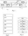
- Figure 1 schematically illustrates a traffic situation, wherein an ego vehicle E travels on a road 1 having at least two adjacent lanes 3, 5 for traffic in the same direction. There may in addition be one or more additional lanes on the road 1 in the same direction and/or in the other direction.
- the ego vehicle E travels in a current lane 3. Adjacent to the current lane 3 there is another lane forming a target lane 5 for a lane change manoeuvre of the ego vehicle E.
- the illustrated traffic situation there are four surrounding vehicles, a first S 1 , a second S 2 , a third S 3 and a fourth S 4 surrounding vehicle.
- the first surrounding vehicle S 1 moves in front of the second surrounding vehicle S 2 in the target lane 5.
- the third surrounding vehicle S 3 moves in front of the fourth surrounding vehicle S 4 in the current lane 3.
- a lane change of the ego vehicle E from its current lane 3 into the target lane 5 is desirable, e.g. when there is a slow-driving preceding vehicle in the current lane 3 or when there is a faster vehicle approaching from behind.
- a lane change may also be desirable when the lane current lane 3 ends, e.g. due to road work.
- the term inter-vehicle traffic gap relates to a longitudinal distance, e.g. expressed in metres between two vehicles.
- the longitudinal distance is the distance as seen in a running direction X of the road 1 and/or along lane markings thereof. If a surrounding vehicle S 1 , S 2 travels in another lane 5 than the ego vehicle E, there is also a lateral distance to the surrounding vehicle S 1 , S 2 . If a surrounding vehicle S 3 , S 4 travels in the same lane 3 as the ego vehicle E, there is a longitudinal distance to the other vehicle S 3 , S 4 , but only a small lateral distance or even no lateral distance.
- the longitudinal position of a vehicle relates to the position as seen in the running direction X of the road. There is also a lateral position component.
- the lateral direction Y is perpendicular to the longitudinal direction X.
- the corresponding space which the ego vehicle E should traverse can be divided into three regions: a safe region in the current lane 7, a lane-change region 9 and an inter-vehicle traffic gap region 11.
- the safe region 7 in the current lane 3 is defined by the objects, e.g. vehicles, pedestrians, and road barriers which the ego vehicle E should account for when approaching the lane-change region 9.
- the ego vehicle E should account for the the third surrounding vehicle S 3 and the fourth surrounding vehicle S 4 in the current lane 3.
- the lane-change region 9 is defined by the environment where the ego vehicle E does not have right-of-way i.e., the objects, e.g. vehicles, pedestrians, and road barriers the ego vehicle E must take into account when performing the lateral motion of the lane change manoeuvre.
- the ego vehicle E should maintain a minimum safe distance to these objects, when it laterally moves from the current lane 3 into the target lane 5.
- the ego vehicle E should account for all four of the surrounding vehicles S 1 , S 2 , S 3 , S 4 in the current lane 3 and the target lane 5.
- the inter-vehicle traffic gap region 11 is defined by the objects, e.g. vehicles, pedestrians, and road barriers which the ego vehicle E should account for after leaving the lane-change region 9.
- the ego vehicle E should account for the first surrounding vehicle S 1 and the second surrounding vehicle S 2 in the target lane 5.
- the ego vehicle E is provided with a system 200 for evaluating a lane change manoeuvre, which system 200 is further described below in conjunction with Figure 2 .
- the system 200 may form part of an automated lane change system.
- the ego vehicle E may further be provided with at least one additional system, which is adapted to determine a position on the road 1 of the ego vehicle E and its velocity, as commonly known in the art.
- Other systems may be adapted to in a known manner determine positions and velocities v 1 , v 2 , v 3 , v 4 of the surrounding vehicles S 1 , S 2 , S 3 , S 4 in relation to the ego vehicle E.
- the system 200 is adapted to select an inter-vehicle traffic gap in the target lane 5, and at which time instance the ego vehicle E should laterally move into the selected inter-vehicle traffic gap.
- the approach for inter-vehicle traffic gap and initiation time selection as described herein determines whether there exists a longitudinal trajectory which allows the ego vehicle E to safely position itself in an inter-vehicle traffic gap in the target lane 5. The approach should thus determine whether a certain inter-vehicle traffic gap is feasible and at which time instance the lane change manoeuvre should be initiated.
- the selection approach is adapted to crudely evaluate which inter-vehicle traffic gap that is most appropriate, e.g. in terms of the control signals, i.e. longitudinal deceleration/acceleration, which are required in order to reach the inter-vehicle traffic gap, and at which time instance to initialize the laterally movement into the selected inter-vehicle traffic gap.
- the control signals i.e. longitudinal deceleration/acceleration
- the feasible set of the ego vehicle E can crudely be approximated by acceleration profiles, e.g. constant acceleration profiles, which may range over a discrete interval from the maximum to the minimum feasible acceleration which satisfies the physical and design limitations of the ego vehicle E.
- the limitations may come from the ego vehicle itself, e.g. its technical performance, but may also be set by external factors, such as road conditions or weather conditions, e.g. a slippery road or a heavy rainfall.
- the most appropriate inter-vehicle traffic gap and time instance for when to initiate the lane change manoeuvre can be selected as the inter-vehicle traffic gap with corresponding time instance which is feasible utilizing the lowest magnitude control signals.
- a safety critical event which should be taken into account is the possibility of any relevant preceding vehicle unexpectedly performing a substantial brake manoeuvre.
- the ego vehicle E should not perform a lane change manoeuvre for which it does not have the ability to avoid a collision if such an event occurs.
- the ego vehicle E when selecting the inter-vehicle traffic gap and time instance for when to initiate the manoeuvre, in addition to a certain acceleration profile allowing the ego vehicle E to enter the lane-change region 9 and remain in that region for the minimum time t min , and thereafter safely be positioned in the inter-vehicle traffic gap region 11 over the prediction horizon, it should also be possible for the ego vehicle E to apply a deceleration profile which allows it to not be closer than the minimum distance ⁇ to the surrounding vehicle at the next time instance.
- the system 200 for evaluating inter-vehicle traffic gaps and time instances to perform a lane change manoeuvre which is illustrated in Figure 2 , comprises a number of units:
- the system 200 may further comprise a sensing system 250, e.g. comprising camera and/or radar monitoring, for determining relative positions and/or velocities of at least one of the surrounding objects S 1 , S 2 , S 3 , S 4 , preferably for all, or substantially all, surrounding objects S 1 , S 2 , S 3 , S 4 . Additionally, or alternatively, the surrounding objects S 1 , S 2 , S 3 , S 4 may transmit information about their positions and/or velocities and the ego vehicle E may receive this information directly or via an information database.
- a sensing system 250 e.g. comprising camera and/or radar monitoring
- an automated lane change system comprising the system for evaluating inter-vehicle traffic gaps and time instances to perform a lane change manoeuvre as disclosed herein.
- an advanced driver assistance system comprising the automated lane change system.
- a vehicle comprising the system 200 for evaluating inter-vehicle traffic gaps and time instances to perform a lane change manoeuvre as described herein, the lane change system and/or the advanced driver assistance system.
- the method as disclosed and described in more detail above is illustrated in Figure 3 .
- the method comprises four steps.
Landscapes
- Engineering & Computer Science (AREA)
- Automation & Control Theory (AREA)
- Transportation (AREA)
- Mechanical Engineering (AREA)
- Physics & Mathematics (AREA)
- General Physics & Mathematics (AREA)
- Human Computer Interaction (AREA)
- Remote Sensing (AREA)
- Radar, Positioning & Navigation (AREA)
- Aviation & Aerospace Engineering (AREA)
- Traffic Control Systems (AREA)
- Business, Economics & Management (AREA)
- Health & Medical Sciences (AREA)
- Artificial Intelligence (AREA)
- Evolutionary Computation (AREA)
- Game Theory and Decision Science (AREA)
- Medical Informatics (AREA)
Abstract
a) determining a set of trajectories which respectively constitutes an approximation of the feasible motion of the ego vehicle,
b) evaluating the set of trajectories on the available inter-vehicle traffic gaps and time instances to perform the lane change manoeuvre over a prediction horizon, to select a subset of feasible inter-vehicle traffic gaps and time instances to perform the lane change manoeuvre and to establish a corresponding set of lane change trajectories,
c) evaluating the set of lane change trajectories on the set of feasible inter-vehicle traffic gaps and time instances from a safety critical perspective, and
d) selecting a preferred lane change trajectory, with corresponding inter-vehicle traffic gap and time instance, to perform the lane change manoeuvre.
Description
- The present disclosure relates to a method and a system for evaluating inter-vehicle traffic gaps and time instances to perform a lane change manoeuvre. The disclosure further relates to an automated lane change system, an advanced driver assistance system and a vehicle.
- When a partially automated, semi-automated or fully automated vehicle drives on a road comprising more than one lane going in the same direction, a lane change is sometimes desirable, e.g. when there is a slow-driving preceding vehicle ahead or when there is a faster vehicle approaching from behind. A lane change may also be desirable when the own lane ends. In order to perform the lane change manoeuvre, an inter-vehicle traffic gap may have to be selected in a target lane as well as a time instance to perform the lane change manoeuvre.
- Advanced driver assistance systems, abbreviated as ADAS, e.g. adaptive cruise control, abbreviated as ACC, lane keeping aid, abbreviated as LKA, and traffic jam assist, abbreviated as TJA, are becoming more and more common as the development towards autonomous or automated vehicles progress. To further increase the autonomous capability of ADAS and eventually progress to fully automated or autonomous driving on e.g. highways, the ability of an ego vehicle to perform lane change manoeuvres is desirable.
- There are various research projects ongoing regarding trajectory planning for lane change manoeuvres. Many of the proposed approaches consider the lane change trajectory planning problem mainly as a lateral planning problem. It is often assumed that given a sufficiently large inter-vehicle traffic gap, the ego vehicle can perform a lateral movement into the target lane.
- However, it may also be desirable to consider the longitudinal planning. There is thus a desire for an improved method and system for evaluating inter-vehicle traffic gaps and time instances to perform a lane change manoeuvre.
- The object of the present disclosure is to overcome or ameliorate at least one of the disadvantages of the prior art, or to provide a useful alternative.
- The object above may be achieved by the subject-matter disclosed herein. Embodiments are set forth in the appended dependent claims, in the following description and in the drawings.
- Thus, according to the invention there is provided a method for evaluating inter-vehicle traffic gaps and time instances to perform a lane change manoeuvre. The method is performed by a system on-board an ego vehicle. The ego vehicle travels in a current lane of a road, which also comprises a target lane adjacent to the current lane. The lane change manoeuvre comprises the ego vehicle changing from the current lane to an inter-vehicle traffic gap in the target lane. The method comprises:
- a) determining a set of trajectories which respectively constitutes an approximation of the feasible motion of the ego vehicle,
- b) evaluating the set of trajectories on available inter-vehicle traffic gaps and time instances to perform the lane change manoeuvre over a prediction horizon to select a subset of feasible inter-vehicle traffic gaps and time instances to perform the lane change manoeuvre and to establish a corresponding set of lane change trajectories,
- c) evaluating the set of lane change trajectories on the set of feasible inter-vehicle traffic gaps and time instances from a safety critical perspective, and
- d) selecting a preferred lane change trajectory, with corresponding inter-vehicle traffic gap and time instance, to perform the lane change manoeuvre.
- The road comprises at least the current lane and the target lane. There may in addition be one or more additional lanes on the road in the same direction and/or in the opposite direction. The current lane is the lane of the ego vehicle before the lane change manoeuvre is started. The target lane is the lane of the ego vehicle after the lane change manoeuvre is finished.
- Sometimes a lane change of the ego vehicle from the current lane into the target lane may be desirable, e.g. when there is a slow-driving preceding vehicle in the current lane or when there is a faster vehicle approaching from behind. A lane change may also be desirable when the current lane ends.
- The method for evaluating inter-vehicle traffic gaps and time instances to perform a lane change manoeuvre as disclosed herein describes a method suitable for automated gap selection. The method may be performed by a system for evaluating inter-vehicle traffic gaps and time instances to perform a lane change manoeuvre, e.g. the system as disclosed herein. The system may form part of an automated lane change system, which may in turn form part of an advanced driver assistance system. The system described herein may be comprised in the ego vehicle. Alternatively, or as a complement, the system may be a separate mobile device, which can be placed and used in the ego vehicle.
- The method as disclosed herein may be performed in a partially automated, semi-automated or fully automated vehicle. In a partially automated vehicle or a semi-automated vehicle, a driver of the vehicle performs some of the driving functions, while the vehicle autonomously performs other functions. If the vehicle is fully automated, the vehicle autonomously performs the driving functions, at least for a temporary period of time. A vehicle may be arranged to be able to change between driving manually, partially automated, semi-automated and/or fully automated.
- The term inter-vehicle traffic gap relates to a longitudinal distance, e.g. expressed in metres between two vehicles. The longitudinal distance is the distance as seen in a running direction of the road and/or along lane markings thereof. If a surrounding vehicle travels in another lane than the ego vehicle, there is also a lateral distance to the surrounding vehicle. If a surrounding vehicle travels in the same lane as the ego vehicle, there is a longitudinal distance to the other vehicle, but only a small lateral distance or even no lateral distance. The longitudinal position of a vehicle relates to the position as seen in the running direction of the road. There is also a lateral position component. The lateral direction is perpendicular to the longitudinal direction.
- In step a, a set of trajectories, which respectively constitutes an approximation of feasible motion of the ego vehicle, are determined.
- The feasible motion of the ego vehicle may be set by physical and/or design constraints of the ego vehicle. The constraints may come from the ego vehicle itself, e.g. its technical performance, but may also be set by external factors, such as road conditions or weather conditions, e.g. a slippery road or a heavy rainfall.
- In step a, a number of acceleration profiles may be assumed, e.g. a number of constant acceleration profiles. The acceleration profiles may be selected to be within a range going from a minimum acceleration of the ego vehicle to a maximum acceleration of the ego vehicle. The minimum acceleration is the same as the maximum deceleration. As mentioned above, the minimum and the maximum acceleration may be set by the physical and/or design constraints of the ego vehicle.
- The prediction horizon is a time period in which the lane change manoeuvre is supposed to occur. The prediction horizon may be in the range of from 1 to 60 seconds, preferably in the range of from 2 to 30 seconds, more preferably in the range of from 5 to 15 seconds, such as for example 10 seconds.
- In step b, the set of trajectories determined in step a are evaluated on the available inter-vehicle traffic gaps and time instances to perform the lane change manoeuvre over the prediction horizon. One, two, three or more inter-vehicle traffic gaps may be considered in the evaluation. The set of available inter-vehicle traffic gaps may comprise the inter-vehicle traffic gaps in the target lane being detected within a sensor range of a sensing system, e.g. comprising camera and/or radar monitoring. The sensor range may vary dependent on kinds of sensors and number of sensors, but may be in the range of from 50 to 200 metres ahead of and behind the ego vehicle, e.g. 100 metres ahead and 100 metres behind the ego vehicle. Being within the sensor range means that the sensor can detect objects being located in a region extending from the ego vehicle, which carries the sensing system, to the sensor range. In the example above, objects could be detected within +/- 0 to 100 metres from the ego vehicle.
- The sensing system of the ego vehicle may be utilized for determining relative positions and/or velocities of at least one surrounding object, preferably for all, or substantially all, surrounding objects, to thereby determine existing inter-vehicle traffic gaps. Additionally, or alternatively, the surrounding objects may transmit information about their positions and/or velocities and the ego vehicle may receive this information directly or via an information database. In that case, the longitudinal extension of the portion of the target lane being searched for available inter-vehicle traffic gaps and time instances to perform the lane change manoeuvre over the prediction horizon may be set to a preselectable value or may be selected dependent on traffic situation and traffic conditions.
- The corresponding space, which the ego vehicle should traverse in order to perform the lane-change manoeuvre, can be divided into three regions: a safe region in the current lane, a lane-change region and an inter-vehicle traffic gap region.
- The safe region in the current lane is defined by the objects, e.g. vehicles, pedestrians, and road barriers, which the ego vehicle should account for - i.e. take into account - when approaching the lane-change region.
- The lane-change region is defined by the environment where the ego vehicle does not have right-of-way i.e. the objects the ego vehicle must take into account when performing the lateral motion of the lane change manoeuvre.
- The inter-vehicle traffic gap region is defined by the objects which the ego vehicle should account for after leaving the lane-change region and moving into the target lane. The inter-vehicle traffic gap region is located in the target lane.
- The minimum time is the minimum time it takes for the ego vehicle to laterally traverse the lane-change region, i.e. the minimum time it takes for the ego vehicle to perform the lateral movement from its current lane into the target lane, e.g. between 1 and 5 seconds, such as 3 seconds.
- As a result of the evaluation in step b, a subset of feasible inter-vehicle traffic gaps and time instances to perform the lane change manoeuvre is selected and a corresponding set of lane change trajectories is established. A certain trajectory is then associated with a certain inter-vehicle traffic gap and a time instance.
- An inter-vehicle traffic gap being feasible means that the inter-vehicle traffic gap is reachable at a certain time instance using one or more of the trajectories in step a. Step b comprises determining if a trajectory determined in step a allows the ego vehicle to enter a corresponding lane change region of a certain inter-vehicle traffic gap and remain in the lane-change region for a minimum time, and thereafter safely be positioned in a corresponding inter-vehicle traffic gap region in the target lane over the prediction horizon.
- To avoid collision conflicts with objects in the surrounding traffic environment, the method may comprise that the ego vehicle should maintain a minimum safe distance ds to the surrounding objects. The minimum safe distance ds may described by

- In step c, the set of lane change trajectories from step b is evaluated on the set of feasible inter-vehicle traffic gaps and time instances from a safety critical perspective.
- Step c may comprise taking a safety critical event into account. A safety critical event is an event, which may threaten the ego vehicle if occurring, such that the ego vehicle may risk becoming involved in an accident.
- The safety critical event may comprise a relevant preceding vehicle, e.g. a vehicle in front of the ego vehicle, making a substantial braking manoeuvre. A substantial braking manoeuvre is characterized in that the braking is performed with the full, or substantially the full capacity of the vehicle. It may then be assumed that the relevant preceding vehicle brakes like an average vehicle.
- Alternatively, or additionally, the safety critical event may comprise that a surrounding vehicle performs a sudden unexpected lane change manoeuvre ahead of the ego vehicle in its current lane.
- When planning a lane change manoeuvre, a safety critical event which may be taken into account is the possibility of any relevant preceding vehicle unexpectedly performing a substantial brake manoeuvre, as mentioned above. To account for this possibility, the ego vehicle should not perform a lane change manoeuvre for which it does not have the ability to avoid a collision if such an event occurs. Thus, when selecting the inter-vehicle traffic gap and time instance for when to initiate the manoeuvre, in addition to a certain acceleration profile allowing the ego vehicle to enter the lane-change region and remain in that region for the minimum time and thereafter safely be positioned in the inter-vehicle traffic gap region over the prediction horizon, it should also be possible for the ego vehicle to apply a deceleration profile which allows it to not be closer than the minimum safe distance to the surrounding vehicle at the next time instance. As such, when determining the most appropriate inter-vehicle traffic gap and time instance for performing the lane change manoeuvre, the possibility of a relevant preceding vehicle performing a substantial brake manoeuvre is accounted for, and thereby it should be possible for the ego vehicle to avoid a collision in such a situation.
- Step d comprises selecting a preferred lane change trajectory with corresponding inter-vehicle traffic gap and time instance, considering the safety critical perspective of step c, to perform the lane change manoeuvre.
- The velocity of the ego vehicle may be constrained in the lane-change region.
- To further account for the possibility of a relevant preceding vehicle unexpectedly performing a substantial brake manoeuvre, whilst in the lane-change region, the velocity of the ego vehicle vx (vt ) in the longitudinal direction x may be constrained to

max denotes the maximum allowed velocity of the ego vehicle E, axmin denotes the minimum acceleration of the ego vehicle E, i.e. the maximum deceleration, and db denotes a possible braking distance defined as e.g.
- The selection in step d may be performed by selecting a trajectory, for which one or more required control signals for the ego vehicle, e.g. longitudinal acceleration/deceleration, has the smallest magnitude considering step b and the safety critical perspective of step c.
- As an alternative, or a complement, the selection in step d may be performed by selecting a preferred inter-vehicle traffic gap as the inter-vehicle traffic gap for which the corresponding lane change region comes first in time considering step b and the safety critical perspective of step c.
- As yet an alternative, the inter-vehicle traffic gap for which the corresponding lane change region is the largest could be selected considering step b and the safety critical perspective of step c.
- According to the invention, there is also provided a system for evaluating inter-vehicle traffic gaps and time instances to perform a lane change manoeuvre. The lane change manoeuvre is performed when the ego vehicle travels in a current lane of a road, which also comprises a target lane adjacent to the current lane. The lane change manoeuvre comprises the ego vehicle changing from the current lane to an inter-vehicle traffic gap in the target lane.
- The system comprises:
- a unit for determining a set of trajectories which respectively constitutes an approximation of feasible motion of the ego vehicle,
- a unit for evaluating the set of trajectories on available inter-vehicle traffic gaps and time instances to perform the lane change manoeuvre over a prediction horizon to select a subset of feasible inter-vehicle traffic gaps and time instances to perform the lane change manoeuvre and to establish a corresponding set of lane change trajectories,
- a unit for evaluating the set of lane change trajectories on the set of feasible inter-vehicle traffic gaps and time instances from a safety critical perspective, and
- a unit for selecting a preferred lane change trajectory, with corresponding inter-vehicle traffic gap and time instance, to perform the lane change manoeuvre.
- The units of the system thus correspond to the steps of the method as disclosed herein, such that the system is suitable for carrying out the method.
- The system may further comprise a sensing system, e.g. comprising camera and/or radar monitoring, for determining relative positions and/or velocities of at least one of the surrounding objects, preferably for all or substantially all surrounding objects.
- According to the invention, there may further be provided an automated lane change system comprising the system for evaluating inter-vehicle traffic gaps and time instances to perform a lane change manoeuvre as disclosed herein.
- In addition, there may be an advanced driver assistance system comprising the automated lane change system.
- Moreover, there may be provided a vehicle comprising the system for evaluating inter-vehicle traffic gaps and time instances to perform a lane change manoeuvre as described herein. Additionally or alternatively, the vehicle may comprise the lane change system and/or the advanced driver assistance system.
- The present invention will hereinafter be further explained by means of non-limiting examples with reference to the appended drawings wherein:
- Fig. 1
- illustrates a traffic situation, wherein an ego vehicle travels on a road,
- Fig. 2
- illustrates an exemplifying system for evaluating inter-vehicle traffic gaps and time instances to perform a lane change manoeuvre according to the invention, and
- Fig. 3
- illustrates an exemplifying method for evaluating inter-vehicle traffic gaps and time instances to perform a lane change manoeuvre according to the invention.
- It should be noted that the appended drawings are not necessarily drawn to scale and that the dimensions of some features of the present invention may have been exaggerated for the sake of clarity.
- The invention will, in the following, be exemplified by embodiments. It should however be realized that the embodiments are included in order to explain principles of the invention and not to limit the scope of the invention, defined by the appended claims. Details from two or more of the embodiments may be combined with each other.
-
Figure 1 schematically illustrates a traffic situation, wherein an ego vehicle E travels on a road 1 having at least twoadjacent lanes current lane 3. Adjacent to thecurrent lane 3 there is another lane forming atarget lane 5 for a lane change manoeuvre of the ego vehicle E. In the illustrated traffic situation there are four surrounding vehicles, a first S1, a second S2, a third S3 and a fourth S4 surrounding vehicle. The first surrounding vehicle S1 moves in front of the second surrounding vehicle S2 in thetarget lane 5. There is thus illustrated an inter-vehicle traffic gap between the first surrounding vehicle S1 and the second surrounding vehicle S2 in thetarget lane 5. The third surrounding vehicle S3 moves in front of the fourth surrounding vehicle S4 in thecurrent lane 3. - Sometimes a lane change of the ego vehicle E from its
current lane 3 into thetarget lane 5 is desirable, e.g. when there is a slow-driving preceding vehicle in thecurrent lane 3 or when there is a faster vehicle approaching from behind. A lane change may also be desirable when the lanecurrent lane 3 ends, e.g. due to road work. - The term inter-vehicle traffic gap relates to a longitudinal distance, e.g. expressed in metres between two vehicles. The longitudinal distance is the distance as seen in a running direction X of the road 1 and/or along lane markings thereof. If a surrounding vehicle S1, S2 travels in another
lane 5 than the ego vehicle E, there is also a lateral distance to the surrounding vehicle S1, S2. If a surrounding vehicle S3, S4 travels in thesame lane 3 as the ego vehicle E, there is a longitudinal distance to the other vehicle S3, S4, but only a small lateral distance or even no lateral distance. The longitudinal position of a vehicle relates to the position as seen in the running direction X of the road. There is also a lateral position component. The lateral direction Y is perpendicular to the longitudinal direction X. - For a certain traffic situation where the ego vehicle E does not have right-of way, like the traffic situation illustrated in
Figure 1 , the corresponding space which the ego vehicle E should traverse can be divided into three regions: a safe region in thecurrent lane 7, a lane-change region 9 and an inter-vehicletraffic gap region 11. - The
safe region 7 in thecurrent lane 3 is defined by the objects, e.g. vehicles, pedestrians, and road barriers which the ego vehicle E should account for when approaching the lane-change region 9. In the traffic situation illustrated inFigure 1 , the ego vehicle E should account for the the third surrounding vehicle S3 and the fourth surrounding vehicle S4 in thecurrent lane 3. - The lane-
change region 9 is defined by the environment where the ego vehicle E does not have right-of-way i.e., the objects, e.g. vehicles, pedestrians, and road barriers the ego vehicle E must take into account when performing the lateral motion of the lane change manoeuvre. The ego vehicle E should maintain a minimum safe distance to these objects, when it laterally moves from thecurrent lane 3 into thetarget lane 5. In the traffic situation illustrated inFigure 1 , the ego vehicle E should account for all four of the surrounding vehicles S1, S2, S3, S4 in thecurrent lane 3 and thetarget lane 5. - The inter-vehicle
traffic gap region 11 is defined by the objects, e.g. vehicles, pedestrians, and road barriers which the ego vehicle E should account for after leaving the lane-change region 9. In the traffic situation illustrated inFigure 1 , the ego vehicle E should account for the first surrounding vehicle S1 and the second surrounding vehicle S2 in thetarget lane 5. - The ego vehicle E is provided with a
system 200 for evaluating a lane change manoeuvre, whichsystem 200 is further described below in conjunction withFigure 2 . Thesystem 200 may form part of an automated lane change system. The ego vehicle E may further be provided with at least one additional system, which is adapted to determine a position on the road 1 of the ego vehicle E and its velocity, as commonly known in the art. Other systems may be adapted to in a known manner determine positions and velocities v1, v2, v3, v4 of the surrounding vehicles S1, S2, S3, S4 in relation to the ego vehicle E. - In order to plan a lane change manoeuvre, the
system 200 is adapted to select an inter-vehicle traffic gap in thetarget lane 5, and at which time instance the ego vehicle E should laterally move into the selected inter-vehicle traffic gap. By considering a lane change manoeuvre as primarily a longitudinal motion planning problem, the approach for inter-vehicle traffic gap and initiation time selection as described herein determines whether there exists a longitudinal trajectory which allows the ego vehicle E to safely position itself in an inter-vehicle traffic gap in thetarget lane 5. The approach should thus determine whether a certain inter-vehicle traffic gap is feasible and at which time instance the lane change manoeuvre should be initiated. As such, the selection approach is adapted to crudely evaluate which inter-vehicle traffic gap that is most appropriate, e.g. in terms of the control signals, i.e. longitudinal deceleration/acceleration, which are required in order to reach the inter-vehicle traffic gap, and at which time instance to initialize the laterally movement into the selected inter-vehicle traffic gap. - To simply estimate whether a certain inter-vehicle traffic gap is feasible, the feasible set of the ego vehicle E can crudely be approximated by acceleration profiles, e.g. constant acceleration profiles, which may range over a discrete interval from the maximum to the minimum feasible acceleration which satisfies the physical and design limitations of the ego vehicle E. The limitations may come from the ego vehicle itself, e.g. its technical performance, but may also be set by external factors, such as road conditions or weather conditions, e.g. a slippery road or a heavy rainfall.
- As such, for each possible inter-vehicle traffic gap and discrete time instance to initialize the lane change manoeuvre, it can easily be determined if a certain acceleration profile allows the ego vehicle E to enter the lane-
change region 9 and remain in that region for a minimum time tmin, and thereafter safely be positioned in the inter-vehicletraffic gap region 11 over the prediction horizon. The minimum time tmin is the minimum time it takes for the ego vehicle E to laterally traverse the lane-change region 9. To allow for smooth and comfortable lane change manoeuvres, the most appropriate inter-vehicle traffic gap and time instance for when to initiate the lane change manoeuvre can be selected as the inter-vehicle traffic gap with corresponding time instance which is feasible utilizing the lowest magnitude control signals. - To avoid collision conflicts with objects in the surrounding traffic environment, the ego vehicle should maintain a minimum safe distance ds to all surrounding objects S1, S2, S3, S4 as described by e.g.

- To further account for uncertainty in the surrounding traffic environment and allow the ego vehicle E the possibility to abort a lane change manoeuvre in order to avoid collision conflicts, additional safety aspects can be considered. When planning a lane change manoeuvre, a safety critical event which should be taken into account is the possibility of any relevant preceding vehicle unexpectedly performing a substantial brake manoeuvre. To account for this possibility, the ego vehicle E should not perform a lane change manoeuvre for which it does not have the ability to avoid a collision if such an event occurs. Thus, when selecting the inter-vehicle traffic gap and time instance for when to initiate the manoeuvre, in addition to a certain acceleration profile allowing the ego vehicle E to enter the lane-
change region 9 and remain in that region for the minimum time tmin, and thereafter safely be positioned in the inter-vehicletraffic gap region 11 over the prediction horizon, it should also be possible for the ego vehicle E to apply a deceleration profile which allows it to not be closer than the minimum distance ε to the surrounding vehicle at the next time instance. As such, when determining the most appropriate inter-vehicle traffic gap and time instance for performing the lane change manoeuvre, the possibility of a relevant preceding vehicle performing a substantial brake manoeuvre is accounted for, and thereby it should be possible for the ego vehicle E to avoid a collision in such a situation. - To further account for the possibility of a relevant preceding vehicle Si, illustrated as the first surrounding vehicle S1 in
Figure 1 , unexpectedly performing a substantial brake manoeuvre, whilst is in the lane-change region 9, the velocity vx (vi ) of the ego vehicle E in the longitudinal direction x is constrained to
max denotes the maximum allowed velocity of the ego vehicle E, axmin denotes the minimum acceleration of the ego vehicle E, i.e. maximum deceleration, and db denotes a possible braking distance defined as e.g.
- The
system 200 for evaluating inter-vehicle traffic gaps and time instances to perform a lane change manoeuvre, which is illustrated inFigure 2 , comprises a number of units: - a
unit 210 for determining a set of trajectories which respectively constitutes an approximation of feasible motion of the ego vehicle E, - a
unit 220 for evaluating the set of trajectories on available inter-vehicle traffic gaps and time instances to perform the lane change manoeuvre over a prediction horizon, to select a subset of feasible inter-vehicle traffic gaps and time instances to perform the lane change manoeuvre and to establish a corresponding set of lane change trajectories, - a
unit 230 for evaluating the set of lane change trajectories on the set of feasible inter-vehicle traffic gaps and time instances from a safety critical perspective, and - a
unit 240 for selecting a preferred lane change trajectory, with corresponding inter-vehicle traffic gap and time instance, to perform the lane change manoeuvre. - The
system 200 may further comprise asensing system 250, e.g. comprising camera and/or radar monitoring, for determining relative positions and/or velocities of at least one of the surrounding objects S1, S2, S3, S4, preferably for all, or substantially all, surrounding objects S1, S2, S3, S4. Additionally, or alternatively, the surrounding objects S1, S2, S3, S4 may transmit information about their positions and/or velocities and the ego vehicle E may receive this information directly or via an information database. - According to the invention, there may further be provided an automated lane change system comprising the system for evaluating inter-vehicle traffic gaps and time instances to perform a lane change manoeuvre as disclosed herein.
- In addition, there may be an advanced driver assistance system comprising the automated lane change system.
- Moreover, there may be provided a vehicle comprising the
system 200 for evaluating inter-vehicle traffic gaps and time instances to perform a lane change manoeuvre as described herein, the lane change system and/or the advanced driver assistance system. - The method as disclosed and described in more detail above is illustrated in
Figure 3 . The method comprises four steps. - 110: Step a comprises determining a set of trajectories which respectively constitutes an approximation of feasible motion of the ego vehicle E,
- 120: Step b comprises evaluating the set of trajectories on available inter-vehicle traffic gaps and time instances to perform the lane change manoeuvre over a prediction horizon, to select a subset of feasible inter-vehicle traffic gaps and time instances to perform the lane change manoeuvre and to establish a corresponding set of lane change trajectories,
- 130: Step c comprises evaluating the set of lane change trajectories on the set of feasible inter-vehicle traffic gaps and time instances from a safety critical perspective, and
- 140: Step d comprises selecting a preferred lane change trajectory, with corresponding inter-vehicle traffic gap and time instance, to perform the lane change manoeuvre.
- Further modifications of the invention within the scope of the appended claims are feasible. As such, the present invention should not be considered as limited by the embodiments and figures described herein. Rather, the full scope of the invention should be determined by the appended claims, with reference to the description and drawings.
Claims (14)
- A method for evaluating inter-vehicle traffic gaps and time instances to perform a lane change manoeuvre, said method being performed by a system (200) on-board an ego vehicle (E), said ego vehicle (E) travelling in a current lane (3) of a road (1), said road (1) also comprising a target lane (5) adjacent to said current lane (3), said lane change manoeuvre comprising said ego vehicle (E) changing from said current lane (3) to an inter-vehicle traffic gap in said target lane (5),
said method comprisinga) determining a set of trajectories which respectively constitutes an approximation of the feasible motion of said ego vehicle (E),b) evaluating said set of trajectories on available inter-vehicle traffic gaps and time instances to perform said lane change manoeuvre over a prediction horizon to select a subset of feasible inter-vehicle traffic gaps and time instances to perform said lane change manoeuvre and to establish a corresponding set of lane change trajectories,c) evaluating said set of lane change trajectories on said set of feasible inter-vehicle traffic gaps and time instances from a safety critical perspective, andd) selecting a preferred lane change trajectory, with corresponding inter-vehicle traffic gap and time instance, to perform said lane change manoeuvre. - The method according to claim 1, wherein a number of acceleration profiles are assumed in step a.
- The method according to claim 1 or 2, wherein said number of acceleration profiles are within a range going from a minimum acceleration of said ego vehicle (E) to a maximum acceleration of said ego vehicle (E).
- The method according to any one of the preceding claims, wherein step b comprises determining if a trajectory determined in step a allows said ego vehicle (E) to enter a corresponding lane-change region (9) of a certain inter-vehicle traffic gap and remain in said lane-change region (9) for a minimum time, and thereafter safely be positioned in a corresponding inter-vehicle traffic gap region (11) in said target lane (5) over the prediction horizon.
- The method according to any one of the preceding claims, wherein step b comprises said ego vehicle (E) maintaining a minimum safe distance to said surrounding objects (S1, S2,..., Si,...Sk).
- The method according to any one of the preceding claims, wherein step c comprises taking a safety critical event into account.
- The method according to claim 6, wherein said safety critical event comprises a preceding vehicle (S1) making a substantial brake manoeuvre.
- The method according to claim 4, or any one of claims 5-7 when dependent on claim 4, wherein a velocity of said ego vehicle (E) is constrained in said lane-change region (9).
- The method according to any one of the preceding claims, wherein step d is performed by selecting a trajectory for which one or more required control signals for said ego vehicle (E), e.g. longitudinal acceleration/deceleration, has the smallest magnitude.
- A system (200) for evaluating inter-vehicle traffic gaps and time instances to perform a lane change manoeuvre, said lane change manoeuvre being performed when said vehicle (E) travels in a current lane (3) of a road (1), said road (1) also comprising a target lane (5) adjacent to said current lane (3), said lane change manoeuvre comprising said ego vehicle (E) changing from said current lane (3) to an inter-vehicle traffic gap in said target lane (5),
said system (200) comprising- a unit (210) for determining a set of trajectories which respectively constitutes an approximation of feasible motion of said ego vehicle (E),- a unit (220) for evaluating said set of trajectories on available inter-vehicle traffic gaps and time instances to perform said lane change manoeuvre over a prediction horizon to select a subset of feasible inter-vehicle traffic gaps and time instances to perform said lane change manoeuvre and to establish a corresponding set of lane change trajectories,- a unit (230) for evaluating said set of lane change trajectories on said set of feasible inter-vehicle traffic gaps and time instances from a safety critical perspective, and- a unit (240) for selecting a preferred lane change trajectory, with corresponding inter-vehicle traffic gap and time instance, to perform said lane change manoeuvre. - The system (200) according to claim 10 further comprising- a sensing system (250) for determining relative positions and/or velocities of at least one of said surrounding objects (S1, S2,..., Si,...Sk).
- An automated lane change system comprising the system according to claim 10 or 11.
- An advanced driver assistance system comprising said automated lane change system according to claim 12.
- A vehicle comprising the system (200) according to claim 10 or 11, the automated lane change system according to claim 12 and/or said advanced driver assistance system according to claim 13.
Priority Applications (3)
| Application Number | Priority Date | Filing Date | Title |
|---|---|---|---|
| EP16156686.4A EP3208786B1 (en) | 2016-02-22 | 2016-02-22 | Method and system for evaluating inter-vehicle traffic gaps and time instances to perform a lane change manoeuvre |
| CN201710303818.4A CN107103784B (en) | 2016-02-22 | 2017-02-15 | Method and system for estimating vehicle separation and time occasions for lane change maneuvers |
| US15/435,815 US10317902B2 (en) | 2016-02-22 | 2017-02-17 | Method and system for evaluating inter-vehicle traffic gaps and time instances to perform a lane change maneuver |
Applications Claiming Priority (1)
| Application Number | Priority Date | Filing Date | Title |
|---|---|---|---|
| EP16156686.4A EP3208786B1 (en) | 2016-02-22 | 2016-02-22 | Method and system for evaluating inter-vehicle traffic gaps and time instances to perform a lane change manoeuvre |
Publications (2)
| Publication Number | Publication Date |
|---|---|
| EP3208786A1 true EP3208786A1 (en) | 2017-08-23 |
| EP3208786B1 EP3208786B1 (en) | 2023-06-07 |
Family
ID=55409772
Family Applications (1)
| Application Number | Title | Priority Date | Filing Date |
|---|---|---|---|
| EP16156686.4A Active EP3208786B1 (en) | 2016-02-22 | 2016-02-22 | Method and system for evaluating inter-vehicle traffic gaps and time instances to perform a lane change manoeuvre |
Country Status (3)
| Country | Link |
|---|---|
| US (1) | US10317902B2 (en) |
| EP (1) | EP3208786B1 (en) |
| CN (1) | CN107103784B (en) |
Cited By (7)
| Publication number | Priority date | Publication date | Assignee | Title |
|---|---|---|---|---|
| KR20180070384A (en) * | 2016-12-16 | 2018-06-26 | 현대자동차주식회사 | Apparatus and method for controlling autonomous driving of vehicle |
| DE102018212033A1 (en) | 2018-07-19 | 2020-01-23 | Robert Bosch Gmbh | Method and control device for determining a travel trajectory for a transverse dynamic driving maneuver for a vehicle |
| CN111783536A (en) * | 2020-05-29 | 2020-10-16 | 北京百度网讯科技有限公司 | Lane change rationality assessment method, device, equipment and storage medium |
| CN115240442A (en) * | 2022-07-26 | 2022-10-25 | 合肥工业大学 | Optimal lane changing control method for following vehicles of front accident vehicles in internet environment and application |
| CN115973192A (en) * | 2022-12-29 | 2023-04-18 | 新石器慧通(北京)科技有限公司 | Vehicle control method and device, electronic device and storage medium |
| EP4119412A4 (en) * | 2020-09-10 | 2023-10-11 | Tencent Technology (Shenzhen) Company Limited | Vehicle-based data processing method and apparatus, computer, and storage medium |
| WO2023208709A1 (en) * | 2022-04-27 | 2023-11-02 | Bayerische Motoren Werke Aktiengesellschaft | Method for assisting a user of a vehicle when maneuvering the vehicle on a multi-lane road by displaying an intention for a planned lane change maneuver, and driver assistance system for a vehicle |
Families Citing this family (56)
| Publication number | Priority date | Publication date | Assignee | Title |
|---|---|---|---|---|
| DE102016214822B4 (en) * | 2016-08-10 | 2022-06-09 | Audi Ag | Method for assisting a driver in driving a motor vehicle |
| JP6592423B2 (en) * | 2016-11-25 | 2019-10-16 | 株式会社デンソー | Vehicle control device |
| JP6575492B2 (en) * | 2016-11-29 | 2019-09-18 | トヨタ自動車株式会社 | Automated driving system |
| WO2018132614A2 (en) * | 2017-01-12 | 2018-07-19 | Mobileye Vision Technologies Ltd. | Rules-based navigation |
| DE102017212607A1 (en) * | 2017-07-21 | 2019-01-24 | Ford Global Technologies, Llc | Method and device for environment-based adaptation of driver assistance system functions |
| US11731614B2 (en) * | 2017-07-25 | 2023-08-22 | Hl Klemove Corp. | Apparatus and method for controlling vehicle to avoid or mitigate collision |
| US20190061765A1 (en) * | 2017-08-23 | 2019-02-28 | Uber Technologies, Inc. | Systems and Methods for Performing Lane Changes Around Obstacles |
| JP6834853B2 (en) * | 2017-08-31 | 2021-02-24 | トヨタ自動車株式会社 | Vehicle control device |
| DE102017011140A1 (en) * | 2017-12-01 | 2019-06-06 | Lucas Automotive Gmbh | Control system and control method for driving a motor vehicle and avoiding a collision with another motor vehicle |
| US11360475B2 (en) * | 2017-12-05 | 2022-06-14 | Waymo Llc | Real-time lane change selection for autonomous vehicles |
| JP6973100B2 (en) * | 2018-01-17 | 2021-11-24 | トヨタ自動車株式会社 | Vehicle driving support system |
| GB2570887B (en) * | 2018-02-07 | 2020-08-12 | Jaguar Land Rover Ltd | A system for a vehicle |
| US20190315361A1 (en) * | 2018-04-11 | 2019-10-17 | Hyundai Motor Company | Apparatus and method for controlling lane change in vehicle |
| US11351989B2 (en) | 2018-04-11 | 2022-06-07 | Hyundai Motor Company | Vehicle driving controller, system including the same, and method thereof |
| US20190315357A1 (en) * | 2018-04-17 | 2019-10-17 | Baidu Usa Llc | Novel method for speed adjustment of autonomous driving vehicles prior to lane change |
| US20200049513A1 (en) * | 2018-08-10 | 2020-02-13 | Delphi Technologies, Llc | Positioning system |
| US10919532B2 (en) * | 2018-12-04 | 2021-02-16 | GM Global Technology Operations LLC | Apparatus and method for longitudinal control in automatic lane change in an assisted driving vehicle |
| US10906549B2 (en) * | 2018-12-07 | 2021-02-02 | Nio Usa, Inc. | Systems and methods of autonomously controlling vehicle lane change maneuver |
| CN109828573B (en) * | 2019-02-20 | 2022-09-20 | 百度在线网络技术(北京)有限公司 | Unmanned vehicle control method, device and storage medium |
| WO2020233772A1 (en) | 2019-05-17 | 2020-11-26 | Volvo Truck Corporation | A method for operating an autonomous vehicle |
| US11613254B2 (en) * | 2019-06-13 | 2023-03-28 | Baidu Usa Llc | Method to monitor control system of autonomous driving vehicle with multiple levels of warning and fail operations |
| US11548511B2 (en) * | 2019-06-14 | 2023-01-10 | GM Global Technology Operations LLC | Method to control vehicle speed to center of a lane change gap |
| US11242060B2 (en) * | 2019-08-26 | 2022-02-08 | GM Global Technology Operations LLC | Maneuver planning for urgent lane changes |
| US11754408B2 (en) * | 2019-10-09 | 2023-09-12 | Argo AI, LLC | Methods and systems for topological planning in autonomous driving |
| DE102019129879A1 (en) * | 2019-11-06 | 2021-05-06 | Zf Friedrichshafen Ag | Method and control device for controlling a motor vehicle |
| EP3822141B1 (en) * | 2019-11-18 | 2023-07-12 | Zenuity AB | Operational design domain validation coverage for adjacent lane relative velocity |
| FR3104518B1 (en) * | 2019-12-13 | 2022-06-24 | Renault Sas | System and method for predicting the trajectory of a vehicle |
| WO2021138160A1 (en) * | 2019-12-30 | 2021-07-08 | Nvidia Corporation | Lane change planning and control in autonomous machine applications |
| US11827247B2 (en) * | 2020-02-19 | 2023-11-28 | Verizon Connect Development Limited | Systems and methods for externally assisted self-driving |
| JP7404925B2 (en) * | 2020-02-21 | 2023-12-26 | 株式会社デンソー | Driving support device, driving support method, and driving support program |
| JP7061148B2 (en) * | 2020-03-31 | 2022-04-27 | 本田技研工業株式会社 | Vehicle control devices, vehicle control methods, and programs |
| US11511751B2 (en) | 2020-05-29 | 2022-11-29 | Toyota Research Institute, Inc. | Merge situation exposure algorithms to maximize exposure time |
| US11608079B2 (en) * | 2020-06-09 | 2023-03-21 | GM Global Technology Operations LLC | System and method to adjust overtake trigger to prevent boxed-in driving situations |
| CN111986514B (en) * | 2020-09-17 | 2021-12-14 | 腾讯科技(深圳)有限公司 | Vehicle-based data processing method, apparatus, device, and medium |
| US12227205B2 (en) * | 2021-01-15 | 2025-02-18 | Tusimple, Inc. | Proactive lane change for autonomous vehicles |
| CN112896140A (en) * | 2021-03-03 | 2021-06-04 | 李解 | Hybrid vehicle with lane-changing collision avoidance system |
| CN113073584B (en) * | 2021-03-31 | 2022-09-16 | 长安大学 | Method for setting graded guide variable marking at exit of multi-lane highway |
| US12024204B2 (en) | 2021-04-09 | 2024-07-02 | Direct Cursus Technology L.L.C | Method of and system for predicting a maneuver of an object |
| US20230009173A1 (en) * | 2021-07-12 | 2023-01-12 | GM Global Technology Operations LLC | Lane change negotiation methods and systems |
| US12499760B2 (en) * | 2021-08-27 | 2025-12-16 | Toyota Motor Engineering & Manufacturing North America, Inc. | Determining a content of a message used to coordinate interactions among vehicles |
| WO2023080393A1 (en) * | 2021-11-04 | 2023-05-11 | 한국과학기술원 | Lane change system for autonomous vehicle |
| US11987237B2 (en) * | 2021-12-20 | 2024-05-21 | Waymo Llc | Systems and methods to determine a lane change strategy at a merge region |
| DE102022104785A1 (en) * | 2022-03-01 | 2023-09-07 | Valeo Schalter Und Sensoren Gmbh | Improved overtaking maneuver for overtaking a third-party vehicle in front |
| US12065173B2 (en) * | 2022-03-29 | 2024-08-20 | Honda Motor Co., Ltd. | System and methods for speed and lane advisory in evaluating lane change events and opportunities |
| CN115416657B (en) * | 2022-09-16 | 2025-04-29 | 中汽创智科技有限公司 | Method, device, equipment and storage medium for determining vehicle drivable area |
| US12565215B2 (en) * | 2022-10-11 | 2026-03-03 | Atieva, Inc. | Multi-policy lane change assistance for vehicle |
| CN116110216B (en) * | 2022-10-21 | 2024-04-12 | 中国第一汽车股份有限公司 | Vehicle line crossing time determining method and device, storage medium and electronic device |
| CN115909783B (en) * | 2022-11-24 | 2025-07-22 | 同济大学 | Lane-level driving assistance method and system based on traffic flow |
| JP7786422B2 (en) * | 2023-04-05 | 2025-12-16 | トヨタ自動車株式会社 | Vehicle control device, control method, and program |
| DE102023204457B3 (en) * | 2023-05-12 | 2024-07-18 | Volkswagen Aktiengesellschaft | Method for selecting a target object for a longitudinal guidance system of a motor vehicle, electronic vehicle guidance system for a motor vehicle and motor vehicle with an electronic vehicle guidance system |
| CN116805445B (en) * | 2023-07-21 | 2024-04-02 | 交通运输部公路科学研究所 | Vehicle lane changing driving control method and system |
| CN116674557B (en) * | 2023-07-31 | 2023-10-31 | 福思(杭州)智能科技有限公司 | Vehicle autonomous lane change dynamic programming method and device and domain controller |
| US20250058781A1 (en) * | 2023-08-18 | 2025-02-20 | Torc Robotics, Inc. | Courtesy lane selection paradigm |
| US12479477B2 (en) * | 2023-08-18 | 2025-11-25 | Torc Robotics, Inc. | Courtesy lane selection paradigm |
| CN121201052A (en) * | 2024-06-26 | 2025-12-26 | 魔门塔(苏州)科技有限公司 | Vehicle lane change speed control methods, devices, electronic equipment and media |
| CN120589030B (en) * | 2025-06-20 | 2025-11-18 | 合肥工业大学 | Automatic driving path optimization control system integrating environment perception and prediction |
Citations (3)
| Publication number | Priority date | Publication date | Assignee | Title |
|---|---|---|---|---|
| DE102011106746A1 (en) * | 2011-06-28 | 2013-01-03 | Deutsches Zentrum für Luft- und Raumfahrt e.V. | Lane change assistance system for motor vehicle, particularly ego vehicle for lane changing from lane to target lane, comprises environment detection unit for detecting surroundings of ego vehicle with respect to nearby vehicles |
| EP2711908A1 (en) * | 2011-05-20 | 2014-03-26 | Honda Motor Co., Ltd. | Lane change assistant system |
| DE102014200896A1 (en) * | 2014-01-20 | 2015-07-23 | Volkswagen Aktiengesellschaft | Lane change assistance for a motor vehicle |
Family Cites Families (37)
| Publication number | Priority date | Publication date | Assignee | Title |
|---|---|---|---|---|
| DE4005444A1 (en) * | 1990-02-21 | 1991-08-22 | Bayerische Motoren Werke Ag | METHOD AND DEVICE FOR SUPPORTING A DRIVER FOR A ROAD TRACK CHANGE |
| DE4313568C1 (en) * | 1993-04-26 | 1994-06-16 | Daimler Benz Ag | Method for guiding a lane change by a motor vehicle |
| WO2002043029A1 (en) * | 2000-11-24 | 2002-05-30 | Aisin Seiki Kabushiki Kaisha | Vehicle collision preventing apparatus |
| JP3925474B2 (en) * | 2003-07-18 | 2007-06-06 | 日産自動車株式会社 | Lane change support device |
| JP2005339241A (en) * | 2004-05-27 | 2005-12-08 | Nissan Motor Co Ltd | Model predictive control device and vehicle recommended operation amount generating device |
| JP2008531388A (en) * | 2005-03-03 | 2008-08-14 | コンティネンタル・テーベス・アクチエンゲゼルシヤフト・ウント・コンパニー・オッフェネ・ハンデルスゲゼルシヤフト | Method and apparatus for avoiding collision when changing lane of vehicle |
| JP4806573B2 (en) * | 2006-02-15 | 2011-11-02 | Udトラックス株式会社 | Vehicle cruise control device |
| JP2008120288A (en) * | 2006-11-14 | 2008-05-29 | Aisin Aw Co Ltd | Driving assistance device |
| JP4207088B2 (en) * | 2007-06-20 | 2009-01-14 | トヨタ自動車株式会社 | Vehicle travel estimation device |
| US20110320163A1 (en) * | 2008-11-06 | 2011-12-29 | Volvo Technology Corporation | Method and system for determining road data |
| JP5672822B2 (en) * | 2010-07-29 | 2015-02-18 | トヨタ自動車株式会社 | Vehicle control system |
| JP2013107431A (en) * | 2011-11-18 | 2013-06-06 | Mitsubishi Motors Corp | Inter-vehicle distance control device |
| US9187117B2 (en) * | 2012-01-17 | 2015-11-17 | Ford Global Technologies, Llc | Autonomous lane control system |
| US9669828B2 (en) * | 2012-06-01 | 2017-06-06 | Toyota Motor Engineering & Manufacturing North America, Inc. | Cooperative driving and collision avoidance by distributed receding horizon control |
| CN102800213B (en) * | 2012-08-27 | 2014-06-18 | 武汉大学 | Traffic-priority-based lane change danger collision avoiding method |
| DE102013210941A1 (en) * | 2013-06-12 | 2014-12-18 | Robert Bosch Gmbh | Method and device for operating a vehicle |
| US9280899B2 (en) * | 2013-08-06 | 2016-03-08 | GM Global Technology Operations LLC | Dynamic safety shields for situation assessment and decision making in collision avoidance tasks |
| JP6119621B2 (en) * | 2014-01-24 | 2017-04-26 | トヨタ自動車株式会社 | Driving assistance device |
| CN103996287B (en) * | 2014-05-26 | 2016-04-06 | 江苏大学 | A kind of vehicle compulsory based on decision-tree model changes decision-making technique |
| KR101664582B1 (en) * | 2014-11-12 | 2016-10-10 | 현대자동차주식회사 | Path Planning Apparatus and Method for Autonomous Vehicle |
| KR102036050B1 (en) * | 2014-12-30 | 2019-10-24 | 주식회사 만도 | Apparatuses and Methods for line changing |
| WO2017010349A1 (en) * | 2015-07-15 | 2017-01-19 | 本田技研工業株式会社 | Vehicle control apparatus, vehicle control method, and vehicle control program |
| US10684133B2 (en) * | 2015-07-22 | 2020-06-16 | Honda Motor Co., Ltd. | Route generator, route generation method, and route generation program |
| JP6446732B2 (en) * | 2015-08-06 | 2019-01-09 | 本田技研工業株式会社 | Vehicle control device, vehicle control method, and vehicle control program |
| CN105303888B (en) * | 2015-09-14 | 2017-11-14 | 奇瑞汽车股份有限公司 | Lane change method of overtaking and device |
| JP6365481B2 (en) * | 2015-09-23 | 2018-08-01 | トヨタ自動車株式会社 | Vehicle travel control device |
| CN204946357U (en) * | 2015-09-25 | 2016-01-06 | 吉林大学 | Vehicle lane-changing inducible system under a kind of accident state |
| DE102015221920A1 (en) * | 2015-11-09 | 2017-05-11 | Bayerische Motoren Werke Aktiengesellschaft | A method, computer program product, apparatus, and vehicle comprising the apparatus for controlling a trajectory planning of an ego vehicle |
| US10108197B2 (en) * | 2015-12-08 | 2018-10-23 | Ford Global Technologies, Llc | Deceleration determination of a vehicle |
| JP6327244B2 (en) * | 2015-12-25 | 2018-05-23 | トヨタ自動車株式会社 | Vehicle control device |
| US9840254B2 (en) * | 2015-12-31 | 2017-12-12 | Sony Corporation | Method and system for adaptive detection and application of horn for an autonomous vehicle |
| US10875541B2 (en) * | 2016-02-12 | 2020-12-29 | Honda Motor Co., Ltd. | Vehicle control system, vehicle control method, and vehicle control program |
| JP6424848B2 (en) * | 2016-02-17 | 2018-11-21 | トヨタ自動車株式会社 | Control device of autonomous driving vehicle |
| JP6645649B2 (en) * | 2016-02-17 | 2020-02-14 | 本田技研工業株式会社 | Vehicle control device, vehicle control method, and vehicle control program |
| JP6319914B2 (en) * | 2016-02-18 | 2018-05-09 | 本田技研工業株式会社 | Vehicle control system, vehicle control method, and vehicle control program |
| JP6630977B2 (en) * | 2016-02-19 | 2020-01-15 | 本田技研工業株式会社 | Vehicle control device |
| US10328973B2 (en) * | 2017-03-06 | 2019-06-25 | Ford Global Technologies, Llc | Assisting drivers with roadway lane changes |
-
2016
- 2016-02-22 EP EP16156686.4A patent/EP3208786B1/en active Active
-
2017
- 2017-02-15 CN CN201710303818.4A patent/CN107103784B/en active Active
- 2017-02-17 US US15/435,815 patent/US10317902B2/en active Active
Patent Citations (3)
| Publication number | Priority date | Publication date | Assignee | Title |
|---|---|---|---|---|
| EP2711908A1 (en) * | 2011-05-20 | 2014-03-26 | Honda Motor Co., Ltd. | Lane change assistant system |
| DE102011106746A1 (en) * | 2011-06-28 | 2013-01-03 | Deutsches Zentrum für Luft- und Raumfahrt e.V. | Lane change assistance system for motor vehicle, particularly ego vehicle for lane changing from lane to target lane, comprises environment detection unit for detecting surroundings of ego vehicle with respect to nearby vehicles |
| DE102014200896A1 (en) * | 2014-01-20 | 2015-07-23 | Volkswagen Aktiengesellschaft | Lane change assistance for a motor vehicle |
Cited By (11)
| Publication number | Priority date | Publication date | Assignee | Title |
|---|---|---|---|---|
| KR20180070384A (en) * | 2016-12-16 | 2018-06-26 | 현대자동차주식회사 | Apparatus and method for controlling autonomous driving of vehicle |
| US10351137B2 (en) * | 2016-12-16 | 2019-07-16 | Hyundai Motor Company | Apparatus and method for controlling autonomous vehicle lane changes |
| DE102018212033A1 (en) | 2018-07-19 | 2020-01-23 | Robert Bosch Gmbh | Method and control device for determining a travel trajectory for a transverse dynamic driving maneuver for a vehicle |
| WO2020015888A1 (en) | 2018-07-19 | 2020-01-23 | Robert Bosch Gmbh | Method and control device for determining a trajectory for a lateral-dynamic driving manoeuvre for a vehicle |
| CN111783536A (en) * | 2020-05-29 | 2020-10-16 | 北京百度网讯科技有限公司 | Lane change rationality assessment method, device, equipment and storage medium |
| EP4119412A4 (en) * | 2020-09-10 | 2023-10-11 | Tencent Technology (Shenzhen) Company Limited | Vehicle-based data processing method and apparatus, computer, and storage medium |
| US12351210B2 (en) | 2020-09-10 | 2025-07-08 | Tencent Technology (Shenzhen) Company Limited | Vehicle-based data processing method and apparatus, computer, and storage medium |
| WO2023208709A1 (en) * | 2022-04-27 | 2023-11-02 | Bayerische Motoren Werke Aktiengesellschaft | Method for assisting a user of a vehicle when maneuvering the vehicle on a multi-lane road by displaying an intention for a planned lane change maneuver, and driver assistance system for a vehicle |
| CN115240442A (en) * | 2022-07-26 | 2022-10-25 | 合肥工业大学 | Optimal lane changing control method for following vehicles of front accident vehicles in internet environment and application |
| CN115240442B (en) * | 2022-07-26 | 2023-05-02 | 合肥工业大学 | Optimal lane-changing control method and application of car-following vehicles in networked environment |
| CN115973192A (en) * | 2022-12-29 | 2023-04-18 | 新石器慧通(北京)科技有限公司 | Vehicle control method and device, electronic device and storage medium |
Also Published As
| Publication number | Publication date |
|---|---|
| CN107103784B (en) | 2021-07-06 |
| US20170242435A1 (en) | 2017-08-24 |
| EP3208786B1 (en) | 2023-06-07 |
| US10317902B2 (en) | 2019-06-11 |
| CN107103784A (en) | 2017-08-29 |
Similar Documents
| Publication | Publication Date | Title |
|---|---|---|
| EP3208786B1 (en) | Method and system for evaluating inter-vehicle traffic gaps and time instances to perform a lane change manoeuvre | |
| JP6704890B2 (en) | Vehicle control device, vehicle control method, and program | |
| EP3407329B1 (en) | Driving assistance method and device | |
| JP7021983B2 (en) | Vehicle control devices, vehicle control methods, and programs | |
| EP3211617B1 (en) | Driving assistance device | |
| JP7201550B2 (en) | VEHICLE CONTROL DEVICE, VEHICLE CONTROL METHOD, AND PROGRAM | |
| JP6823512B2 (en) | Route determination device, vehicle control device, route determination method, and program | |
| CN109426263B (en) | Vehicle control device, vehicle control method, and storage medium | |
| EP3825979B1 (en) | Travel assistance method and travel assistance device | |
| EP2950294B1 (en) | Method and vehicle with an advanced driver assistance system for risk-based traffic scene analysis | |
| EP3410418B1 (en) | Vehicle travel control method and vehicle travel control device | |
| US12017648B2 (en) | Vehicle control device | |
| CN107031636B (en) | Method and system for gap selection | |
| CN103935361B (en) | For autonomous lane changing, process and the valid data flow algorithm surmounting behavior | |
| US20230123418A1 (en) | Method for planning a target trajectory | |
| US9159023B2 (en) | System for predicting a driver's intention to change lanes | |
| CN110271542B (en) | Vehicle control device, vehicle control method, and storage medium | |
| US20190286149A1 (en) | Vehicle control device | |
| JP2019151207A (en) | Vehicle control device, vehicle control method, and program | |
| EP3696789A1 (en) | Driving control method and driving control apparatus | |
| CN109835343B (en) | Vehicle control device, vehicle control method, and storage medium | |
| JP6583697B2 (en) | Perimeter monitoring device, control device, perimeter monitoring method, and program | |
| JP2019160031A (en) | Vehicle control device, vehicle control method, and program | |
| JP2020083106A (en) | Vehicle control device, vehicle control method, and program | |
| CN114506316B (en) | Vehicle control device, vehicle control method and storage medium |
Legal Events
| Date | Code | Title | Description |
|---|---|---|---|
| PUAI | Public reference made under article 153(3) epc to a published international application that has entered the european phase |
Free format text: ORIGINAL CODE: 0009012 |
|
| STAA | Information on the status of an ep patent application or granted ep patent |
Free format text: STATUS: THE APPLICATION HAS BEEN PUBLISHED |
|
| AK | Designated contracting states |
Kind code of ref document: A1 Designated state(s): AL AT BE BG CH CY CZ DE DK EE ES FI FR GB GR HR HU IE IS IT LI LT LU LV MC MK MT NL NO PL PT RO RS SE SI SK SM TR |
|
| AX | Request for extension of the european patent |
Extension state: BA ME |
|
| STAA | Information on the status of an ep patent application or granted ep patent |
Free format text: STATUS: REQUEST FOR EXAMINATION WAS MADE |
|
| 17P | Request for examination filed |
Effective date: 20180223 |
|
| RBV | Designated contracting states (corrected) |
Designated state(s): AL AT BE BG CH CY CZ DE DK EE ES FI FR GB GR HR HU IE IS IT LI LT LU LV MC MK MT NL NO PL PT RO RS SE SI SK SM TR |
|
| STAA | Information on the status of an ep patent application or granted ep patent |
Free format text: STATUS: EXAMINATION IS IN PROGRESS |
|
| 17Q | First examination report despatched |
Effective date: 20210211 |
|
| GRAP | Despatch of communication of intention to grant a patent |
Free format text: ORIGINAL CODE: EPIDOSNIGR1 |
|
| STAA | Information on the status of an ep patent application or granted ep patent |
Free format text: STATUS: GRANT OF PATENT IS INTENDED |
|
| INTG | Intention to grant announced |
Effective date: 20230125 |
|
| GRAS | Grant fee paid |
Free format text: ORIGINAL CODE: EPIDOSNIGR3 |
|
| GRAA | (expected) grant |
Free format text: ORIGINAL CODE: 0009210 |
|
| STAA | Information on the status of an ep patent application or granted ep patent |
Free format text: STATUS: THE PATENT HAS BEEN GRANTED |
|
| AK | Designated contracting states |
Kind code of ref document: B1 Designated state(s): AL AT BE BG CH CY CZ DE DK EE ES FI FR GB GR HR HU IE IS IT LI LT LU LV MC MK MT NL NO PL PT RO RS SE SI SK SM TR |
|
| REG | Reference to a national code |
Ref country code: GB Ref legal event code: FG4D |
|
| REG | Reference to a national code |
Ref country code: CH Ref legal event code: EP Ref country code: AT Ref legal event code: REF Ref document number: 1577343 Country of ref document: AT Kind code of ref document: T Effective date: 20230615 |
|
| REG | Reference to a national code |
Ref country code: DE Ref legal event code: R096 Ref document number: 602016079790 Country of ref document: DE |
|
| REG | Reference to a national code |
Ref country code: LT Ref legal event code: MG9D |
|
| REG | Reference to a national code |
Ref country code: NL Ref legal event code: MP Effective date: 20230607 |
|
| PG25 | Lapsed in a contracting state [announced via postgrant information from national office to epo] |
Ref country code: SE Free format text: LAPSE BECAUSE OF FAILURE TO SUBMIT A TRANSLATION OF THE DESCRIPTION OR TO PAY THE FEE WITHIN THE PRESCRIBED TIME-LIMIT Effective date: 20230607 Ref country code: NO Free format text: LAPSE BECAUSE OF FAILURE TO SUBMIT A TRANSLATION OF THE DESCRIPTION OR TO PAY THE FEE WITHIN THE PRESCRIBED TIME-LIMIT Effective date: 20230907 Ref country code: ES Free format text: LAPSE BECAUSE OF FAILURE TO SUBMIT A TRANSLATION OF THE DESCRIPTION OR TO PAY THE FEE WITHIN THE PRESCRIBED TIME-LIMIT Effective date: 20230607 |
|
| REG | Reference to a national code |
Ref country code: AT Ref legal event code: MK05 Ref document number: 1577343 Country of ref document: AT Kind code of ref document: T Effective date: 20230607 |
|
| PG25 | Lapsed in a contracting state [announced via postgrant information from national office to epo] |
Ref country code: RS Free format text: LAPSE BECAUSE OF FAILURE TO SUBMIT A TRANSLATION OF THE DESCRIPTION OR TO PAY THE FEE WITHIN THE PRESCRIBED TIME-LIMIT Effective date: 20230607 Ref country code: NL Free format text: LAPSE BECAUSE OF FAILURE TO SUBMIT A TRANSLATION OF THE DESCRIPTION OR TO PAY THE FEE WITHIN THE PRESCRIBED TIME-LIMIT Effective date: 20230607 Ref country code: LV Free format text: LAPSE BECAUSE OF FAILURE TO SUBMIT A TRANSLATION OF THE DESCRIPTION OR TO PAY THE FEE WITHIN THE PRESCRIBED TIME-LIMIT Effective date: 20230607 Ref country code: LT Free format text: LAPSE BECAUSE OF FAILURE TO SUBMIT A TRANSLATION OF THE DESCRIPTION OR TO PAY THE FEE WITHIN THE PRESCRIBED TIME-LIMIT Effective date: 20230607 Ref country code: HR Free format text: LAPSE BECAUSE OF FAILURE TO SUBMIT A TRANSLATION OF THE DESCRIPTION OR TO PAY THE FEE WITHIN THE PRESCRIBED TIME-LIMIT Effective date: 20230607 Ref country code: GR Free format text: LAPSE BECAUSE OF FAILURE TO SUBMIT A TRANSLATION OF THE DESCRIPTION OR TO PAY THE FEE WITHIN THE PRESCRIBED TIME-LIMIT Effective date: 20230908 |
|
| PG25 | Lapsed in a contracting state [announced via postgrant information from national office to epo] |
Ref country code: FI Free format text: LAPSE BECAUSE OF FAILURE TO SUBMIT A TRANSLATION OF THE DESCRIPTION OR TO PAY THE FEE WITHIN THE PRESCRIBED TIME-LIMIT Effective date: 20230607 |
|
| PG25 | Lapsed in a contracting state [announced via postgrant information from national office to epo] |
Ref country code: SK Free format text: LAPSE BECAUSE OF FAILURE TO SUBMIT A TRANSLATION OF THE DESCRIPTION OR TO PAY THE FEE WITHIN THE PRESCRIBED TIME-LIMIT Effective date: 20230607 |
|
| P01 | Opt-out of the competence of the unified patent court (upc) registered |
Effective date: 20231212 |
|
| PG25 | Lapsed in a contracting state [announced via postgrant information from national office to epo] |
Ref country code: IS Free format text: LAPSE BECAUSE OF FAILURE TO SUBMIT A TRANSLATION OF THE DESCRIPTION OR TO PAY THE FEE WITHIN THE PRESCRIBED TIME-LIMIT Effective date: 20231007 |
|
| PG25 | Lapsed in a contracting state [announced via postgrant information from national office to epo] |
Ref country code: SM Free format text: LAPSE BECAUSE OF FAILURE TO SUBMIT A TRANSLATION OF THE DESCRIPTION OR TO PAY THE FEE WITHIN THE PRESCRIBED TIME-LIMIT Effective date: 20230607 Ref country code: SK Free format text: LAPSE BECAUSE OF FAILURE TO SUBMIT A TRANSLATION OF THE DESCRIPTION OR TO PAY THE FEE WITHIN THE PRESCRIBED TIME-LIMIT Effective date: 20230607 Ref country code: RO Free format text: LAPSE BECAUSE OF FAILURE TO SUBMIT A TRANSLATION OF THE DESCRIPTION OR TO PAY THE FEE WITHIN THE PRESCRIBED TIME-LIMIT Effective date: 20230607 Ref country code: PT Free format text: LAPSE BECAUSE OF FAILURE TO SUBMIT A TRANSLATION OF THE DESCRIPTION OR TO PAY THE FEE WITHIN THE PRESCRIBED TIME-LIMIT Effective date: 20231009 Ref country code: IS Free format text: LAPSE BECAUSE OF FAILURE TO SUBMIT A TRANSLATION OF THE DESCRIPTION OR TO PAY THE FEE WITHIN THE PRESCRIBED TIME-LIMIT Effective date: 20231007 Ref country code: EE Free format text: LAPSE BECAUSE OF FAILURE TO SUBMIT A TRANSLATION OF THE DESCRIPTION OR TO PAY THE FEE WITHIN THE PRESCRIBED TIME-LIMIT Effective date: 20230607 Ref country code: CZ Free format text: LAPSE BECAUSE OF FAILURE TO SUBMIT A TRANSLATION OF THE DESCRIPTION OR TO PAY THE FEE WITHIN THE PRESCRIBED TIME-LIMIT Effective date: 20230607 Ref country code: AT Free format text: LAPSE BECAUSE OF FAILURE TO SUBMIT A TRANSLATION OF THE DESCRIPTION OR TO PAY THE FEE WITHIN THE PRESCRIBED TIME-LIMIT Effective date: 20230607 |
|
| PG25 | Lapsed in a contracting state [announced via postgrant information from national office to epo] |
Ref country code: PL Free format text: LAPSE BECAUSE OF FAILURE TO SUBMIT A TRANSLATION OF THE DESCRIPTION OR TO PAY THE FEE WITHIN THE PRESCRIBED TIME-LIMIT Effective date: 20230607 |
|
| REG | Reference to a national code |
Ref country code: DE Ref legal event code: R097 Ref document number: 602016079790 Country of ref document: DE |
|
| PLBE | No opposition filed within time limit |
Free format text: ORIGINAL CODE: 0009261 |
|
| STAA | Information on the status of an ep patent application or granted ep patent |
Free format text: STATUS: NO OPPOSITION FILED WITHIN TIME LIMIT |
|
| PG25 | Lapsed in a contracting state [announced via postgrant information from national office to epo] |
Ref country code: DK Free format text: LAPSE BECAUSE OF FAILURE TO SUBMIT A TRANSLATION OF THE DESCRIPTION OR TO PAY THE FEE WITHIN THE PRESCRIBED TIME-LIMIT Effective date: 20230607 |
|
| PG25 | Lapsed in a contracting state [announced via postgrant information from national office to epo] |
Ref country code: SI Free format text: LAPSE BECAUSE OF FAILURE TO SUBMIT A TRANSLATION OF THE DESCRIPTION OR TO PAY THE FEE WITHIN THE PRESCRIBED TIME-LIMIT Effective date: 20230607 |
|
| 26N | No opposition filed |
Effective date: 20240308 |
|
| PG25 | Lapsed in a contracting state [announced via postgrant information from national office to epo] |
Ref country code: SI Free format text: LAPSE BECAUSE OF FAILURE TO SUBMIT A TRANSLATION OF THE DESCRIPTION OR TO PAY THE FEE WITHIN THE PRESCRIBED TIME-LIMIT Effective date: 20230607 Ref country code: IT Free format text: LAPSE BECAUSE OF FAILURE TO SUBMIT A TRANSLATION OF THE DESCRIPTION OR TO PAY THE FEE WITHIN THE PRESCRIBED TIME-LIMIT Effective date: 20230607 |
|
| PG25 | Lapsed in a contracting state [announced via postgrant information from national office to epo] |
Ref country code: MC Free format text: LAPSE BECAUSE OF FAILURE TO SUBMIT A TRANSLATION OF THE DESCRIPTION OR TO PAY THE FEE WITHIN THE PRESCRIBED TIME-LIMIT Effective date: 20230607 |
|
| REG | Reference to a national code |
Ref country code: CH Ref legal event code: PL |
|
| PG25 | Lapsed in a contracting state [announced via postgrant information from national office to epo] |
Ref country code: LU Free format text: LAPSE BECAUSE OF NON-PAYMENT OF DUE FEES Effective date: 20240222 |
|
| PG25 | Lapsed in a contracting state [announced via postgrant information from national office to epo] |
Ref country code: CH Free format text: LAPSE BECAUSE OF NON-PAYMENT OF DUE FEES Effective date: 20240229 |
|
| PG25 | Lapsed in a contracting state [announced via postgrant information from national office to epo] |
Ref country code: LU Free format text: LAPSE BECAUSE OF NON-PAYMENT OF DUE FEES Effective date: 20240222 Ref country code: CH Free format text: LAPSE BECAUSE OF NON-PAYMENT OF DUE FEES Effective date: 20240229 |
|
| PG25 | Lapsed in a contracting state [announced via postgrant information from national office to epo] |
Ref country code: BG Free format text: LAPSE BECAUSE OF FAILURE TO SUBMIT A TRANSLATION OF THE DESCRIPTION OR TO PAY THE FEE WITHIN THE PRESCRIBED TIME-LIMIT Effective date: 20230607 |
|
| PG25 | Lapsed in a contracting state [announced via postgrant information from national office to epo] |
Ref country code: BG Free format text: LAPSE BECAUSE OF FAILURE TO SUBMIT A TRANSLATION OF THE DESCRIPTION OR TO PAY THE FEE WITHIN THE PRESCRIBED TIME-LIMIT Effective date: 20230607 |
|
| REG | Reference to a national code |
Ref country code: BE Ref legal event code: MM Effective date: 20240229 |
|
| PG25 | Lapsed in a contracting state [announced via postgrant information from national office to epo] |
Ref country code: BE Free format text: LAPSE BECAUSE OF NON-PAYMENT OF DUE FEES Effective date: 20240229 |
|
| PG25 | Lapsed in a contracting state [announced via postgrant information from national office to epo] |
Ref country code: IE Free format text: LAPSE BECAUSE OF NON-PAYMENT OF DUE FEES Effective date: 20240222 |
|
| PG25 | Lapsed in a contracting state [announced via postgrant information from national office to epo] |
Ref country code: IE Free format text: LAPSE BECAUSE OF NON-PAYMENT OF DUE FEES Effective date: 20240222 Ref country code: BE Free format text: LAPSE BECAUSE OF NON-PAYMENT OF DUE FEES Effective date: 20240229 |
|
| PG25 | Lapsed in a contracting state [announced via postgrant information from national office to epo] |
Ref country code: CY Free format text: LAPSE BECAUSE OF FAILURE TO SUBMIT A TRANSLATION OF THE DESCRIPTION OR TO PAY THE FEE WITHIN THE PRESCRIBED TIME-LIMIT; INVALID AB INITIO Effective date: 20160222 |
|
| PG25 | Lapsed in a contracting state [announced via postgrant information from national office to epo] |
Ref country code: HU Free format text: LAPSE BECAUSE OF FAILURE TO SUBMIT A TRANSLATION OF THE DESCRIPTION OR TO PAY THE FEE WITHIN THE PRESCRIBED TIME-LIMIT; INVALID AB INITIO Effective date: 20160222 |
|
| PG25 | Lapsed in a contracting state [announced via postgrant information from national office to epo] |
Ref country code: TR Free format text: LAPSE BECAUSE OF FAILURE TO SUBMIT A TRANSLATION OF THE DESCRIPTION OR TO PAY THE FEE WITHIN THE PRESCRIBED TIME-LIMIT Effective date: 20230607 |
|
| PGFP | Annual fee paid to national office [announced via postgrant information from national office to epo] |
Ref country code: GB Payment date: 20260121 Year of fee payment: 11 |
|
| PGFP | Annual fee paid to national office [announced via postgrant information from national office to epo] |
Ref country code: DE Payment date: 20260121 Year of fee payment: 11 |
|
| PGFP | Annual fee paid to national office [announced via postgrant information from national office to epo] |
Ref country code: FR Payment date: 20260121 Year of fee payment: 11 |