US11511751B2 - Merge situation exposure algorithms to maximize exposure time - Google Patents
Merge situation exposure algorithms to maximize exposure time Download PDFInfo
- Publication number
- US11511751B2 US11511751B2 US16/888,330 US202016888330A US11511751B2 US 11511751 B2 US11511751 B2 US 11511751B2 US 202016888330 A US202016888330 A US 202016888330A US 11511751 B2 US11511751 B2 US 11511751B2
- Authority
- US
- United States
- Prior art keywords
- vehicle
- merge
- exposure time
- gaps
- ego
- Prior art date
- Legal status (The legal status is an assumption and is not a legal conclusion. Google has not performed a legal analysis and makes no representation as to the accuracy of the status listed.)
- Active, expires
Links
- 238000000034 method Methods 0.000 claims abstract description 50
- 238000004891 communication Methods 0.000 claims description 36
- 230000009471 action Effects 0.000 claims description 35
- 230000001133 acceleration Effects 0.000 claims description 25
- 230000008447 perception Effects 0.000 claims description 10
- 238000013527 convolutional neural network Methods 0.000 claims description 6
- 230000006399 behavior Effects 0.000 description 39
- 238000012545 processing Methods 0.000 description 23
- 230000006870 function Effects 0.000 description 18
- 239000003795 chemical substances by application Substances 0.000 description 11
- 230000008859 change Effects 0.000 description 10
- 238000010801 machine learning Methods 0.000 description 10
- 238000010586 diagram Methods 0.000 description 9
- 230000002123 temporal effect Effects 0.000 description 9
- 230000008901 benefit Effects 0.000 description 7
- 238000004590 computer program Methods 0.000 description 6
- 230000033001 locomotion Effects 0.000 description 6
- 238000005516 engineering process Methods 0.000 description 5
- 238000013528 artificial neural network Methods 0.000 description 4
- 230000005540 biological transmission Effects 0.000 description 4
- 238000013461 design Methods 0.000 description 4
- 238000001514 detection method Methods 0.000 description 4
- 238000012552 review Methods 0.000 description 4
- 238000005259 measurement Methods 0.000 description 3
- 230000001537 neural effect Effects 0.000 description 3
- 230000003287 optical effect Effects 0.000 description 3
- 238000012546 transfer Methods 0.000 description 3
- 206010039203 Road traffic accident Diseases 0.000 description 2
- 238000013473 artificial intelligence Methods 0.000 description 2
- 239000000835 fiber Substances 0.000 description 2
- 239000012530 fluid Substances 0.000 description 2
- 230000006872 improvement Effects 0.000 description 2
- 230000003993 interaction Effects 0.000 description 2
- 230000007774 longterm Effects 0.000 description 2
- 238000007726 management method Methods 0.000 description 2
- 239000005022 packaging material Substances 0.000 description 2
- 230000002093 peripheral effect Effects 0.000 description 2
- 230000008569 process Effects 0.000 description 2
- 230000000007 visual effect Effects 0.000 description 2
- 241000282412 Homo Species 0.000 description 1
- 230000003044 adaptive effect Effects 0.000 description 1
- 238000003491 array Methods 0.000 description 1
- 230000010267 cellular communication Effects 0.000 description 1
- 230000001413 cellular effect Effects 0.000 description 1
- 238000010276 construction Methods 0.000 description 1
- 230000008878 coupling Effects 0.000 description 1
- 238000010168 coupling process Methods 0.000 description 1
- 238000005859 coupling reaction Methods 0.000 description 1
- 230000001934 delay Effects 0.000 description 1
- 230000001788 irregular Effects 0.000 description 1
- 238000012986 modification Methods 0.000 description 1
- 230000004048 modification Effects 0.000 description 1
- 210000002569 neuron Anatomy 0.000 description 1
- 230000008520 organization Effects 0.000 description 1
- 230000010355 oscillation Effects 0.000 description 1
- 230000000946 synaptic effect Effects 0.000 description 1
Images


Classifications
-
- B—PERFORMING OPERATIONS; TRANSPORTING
- B60—VEHICLES IN GENERAL
- B60W—CONJOINT CONTROL OF VEHICLE SUB-UNITS OF DIFFERENT TYPE OR DIFFERENT FUNCTION; CONTROL SYSTEMS SPECIALLY ADAPTED FOR HYBRID VEHICLES; ROAD VEHICLE DRIVE CONTROL SYSTEMS FOR PURPOSES NOT RELATED TO THE CONTROL OF A PARTICULAR SUB-UNIT
- B60W30/00—Purposes of road vehicle drive control systems not related to the control of a particular sub-unit, e.g. of systems using conjoint control of vehicle sub-units
- B60W30/18—Propelling the vehicle
- B60W30/18009—Propelling the vehicle related to particular drive situations
- B60W30/18163—Lane change; Overtaking manoeuvres
-
- B—PERFORMING OPERATIONS; TRANSPORTING
- B60—VEHICLES IN GENERAL
- B60W—CONJOINT CONTROL OF VEHICLE SUB-UNITS OF DIFFERENT TYPE OR DIFFERENT FUNCTION; CONTROL SYSTEMS SPECIALLY ADAPTED FOR HYBRID VEHICLES; ROAD VEHICLE DRIVE CONTROL SYSTEMS FOR PURPOSES NOT RELATED TO THE CONTROL OF A PARTICULAR SUB-UNIT
- B60W30/00—Purposes of road vehicle drive control systems not related to the control of a particular sub-unit, e.g. of systems using conjoint control of vehicle sub-units
- B60W30/14—Adaptive cruise control
- B60W30/143—Speed control
-
- B—PERFORMING OPERATIONS; TRANSPORTING
- B60—VEHICLES IN GENERAL
- B60W—CONJOINT CONTROL OF VEHICLE SUB-UNITS OF DIFFERENT TYPE OR DIFFERENT FUNCTION; CONTROL SYSTEMS SPECIALLY ADAPTED FOR HYBRID VEHICLES; ROAD VEHICLE DRIVE CONTROL SYSTEMS FOR PURPOSES NOT RELATED TO THE CONTROL OF A PARTICULAR SUB-UNIT
- B60W30/00—Purposes of road vehicle drive control systems not related to the control of a particular sub-unit, e.g. of systems using conjoint control of vehicle sub-units
- B60W30/18—Propelling the vehicle
- B60W30/18009—Propelling the vehicle related to particular drive situations
- B60W30/18109—Braking
-
- B—PERFORMING OPERATIONS; TRANSPORTING
- B60—VEHICLES IN GENERAL
- B60W—CONJOINT CONTROL OF VEHICLE SUB-UNITS OF DIFFERENT TYPE OR DIFFERENT FUNCTION; CONTROL SYSTEMS SPECIALLY ADAPTED FOR HYBRID VEHICLES; ROAD VEHICLE DRIVE CONTROL SYSTEMS FOR PURPOSES NOT RELATED TO THE CONTROL OF A PARTICULAR SUB-UNIT
- B60W60/00—Drive control systems specially adapted for autonomous road vehicles
- B60W60/001—Planning or execution of driving tasks
- B60W60/0025—Planning or execution of driving tasks specially adapted for specific operations
-
- H—ELECTRICITY
- H04—ELECTRIC COMMUNICATION TECHNIQUE
- H04W—WIRELESS COMMUNICATION NETWORKS
- H04W4/00—Services specially adapted for wireless communication networks; Facilities therefor
- H04W4/30—Services specially adapted for particular environments, situations or purposes
- H04W4/40—Services specially adapted for particular environments, situations or purposes for vehicles, e.g. vehicle-to-pedestrians [V2P]
-
- B—PERFORMING OPERATIONS; TRANSPORTING
- B60—VEHICLES IN GENERAL
- B60W—CONJOINT CONTROL OF VEHICLE SUB-UNITS OF DIFFERENT TYPE OR DIFFERENT FUNCTION; CONTROL SYSTEMS SPECIALLY ADAPTED FOR HYBRID VEHICLES; ROAD VEHICLE DRIVE CONTROL SYSTEMS FOR PURPOSES NOT RELATED TO THE CONTROL OF A PARTICULAR SUB-UNIT
- B60W2552/00—Input parameters relating to infrastructure
- B60W2552/05—Type of road, e.g. motorways, local streets, paved or unpaved roads
-
- B—PERFORMING OPERATIONS; TRANSPORTING
- B60—VEHICLES IN GENERAL
- B60W—CONJOINT CONTROL OF VEHICLE SUB-UNITS OF DIFFERENT TYPE OR DIFFERENT FUNCTION; CONTROL SYSTEMS SPECIALLY ADAPTED FOR HYBRID VEHICLES; ROAD VEHICLE DRIVE CONTROL SYSTEMS FOR PURPOSES NOT RELATED TO THE CONTROL OF A PARTICULAR SUB-UNIT
- B60W2552/00—Input parameters relating to infrastructure
- B60W2552/10—Number of lanes
-
- B—PERFORMING OPERATIONS; TRANSPORTING
- B60—VEHICLES IN GENERAL
- B60W—CONJOINT CONTROL OF VEHICLE SUB-UNITS OF DIFFERENT TYPE OR DIFFERENT FUNCTION; CONTROL SYSTEMS SPECIALLY ADAPTED FOR HYBRID VEHICLES; ROAD VEHICLE DRIVE CONTROL SYSTEMS FOR PURPOSES NOT RELATED TO THE CONTROL OF A PARTICULAR SUB-UNIT
- B60W2554/00—Input parameters relating to objects
- B60W2554/40—Dynamic objects, e.g. animals, windblown objects
- B60W2554/404—Characteristics
- B60W2554/4041—Position
-
- B—PERFORMING OPERATIONS; TRANSPORTING
- B60—VEHICLES IN GENERAL
- B60W—CONJOINT CONTROL OF VEHICLE SUB-UNITS OF DIFFERENT TYPE OR DIFFERENT FUNCTION; CONTROL SYSTEMS SPECIALLY ADAPTED FOR HYBRID VEHICLES; ROAD VEHICLE DRIVE CONTROL SYSTEMS FOR PURPOSES NOT RELATED TO THE CONTROL OF A PARTICULAR SUB-UNIT
- B60W2554/00—Input parameters relating to objects
- B60W2554/40—Dynamic objects, e.g. animals, windblown objects
- B60W2554/404—Characteristics
- B60W2554/4042—Longitudinal speed
-
- B—PERFORMING OPERATIONS; TRANSPORTING
- B60—VEHICLES IN GENERAL
- B60W—CONJOINT CONTROL OF VEHICLE SUB-UNITS OF DIFFERENT TYPE OR DIFFERENT FUNCTION; CONTROL SYSTEMS SPECIALLY ADAPTED FOR HYBRID VEHICLES; ROAD VEHICLE DRIVE CONTROL SYSTEMS FOR PURPOSES NOT RELATED TO THE CONTROL OF A PARTICULAR SUB-UNIT
- B60W2556/00—Input parameters relating to data
- B60W2556/45—External transmission of data to or from the vehicle
- B60W2556/65—Data transmitted between vehicles
-
- B—PERFORMING OPERATIONS; TRANSPORTING
- B60—VEHICLES IN GENERAL
- B60W—CONJOINT CONTROL OF VEHICLE SUB-UNITS OF DIFFERENT TYPE OR DIFFERENT FUNCTION; CONTROL SYSTEMS SPECIALLY ADAPTED FOR HYBRID VEHICLES; ROAD VEHICLE DRIVE CONTROL SYSTEMS FOR PURPOSES NOT RELATED TO THE CONTROL OF A PARTICULAR SUB-UNIT
- B60W2720/00—Output or target parameters relating to overall vehicle dynamics
- B60W2720/10—Longitudinal speed
- B60W2720/106—Longitudinal acceleration
-
- H—ELECTRICITY
- H04—ELECTRIC COMMUNICATION TECHNIQUE
- H04W—WIRELESS COMMUNICATION NETWORKS
- H04W4/00—Services specially adapted for wireless communication networks; Facilities therefor
- H04W4/02—Services making use of location information
- H04W4/029—Location-based management or tracking services
Definitions
- Certain aspects of the present disclosure generally relate to autonomous vehicle technology and, more particularly, to merge situation exposure algorithms to maximize exposure time.
- Machine vision e.g., vehicles, robots, etc.
- Machine vision involves recovering a three-dimensional (3D) structure of the world from images and using the 3D structure for fully understanding a scene. That is, machine vision strives to provide a high-level understanding of a surrounding environment, as performed by the human visual system.
- Machine learning techniques for vehicle control using a network to select a vehicle control action for an ego vehicle are desired. For example, a selected speed/acceleration/steering angle of the controlled (ego) vehicle may be applied as a vehicle control action.
- These conventional machine learning techniques do not consider a temporal component of a current traffic state for selecting vehicle control actions.
- a method of improving a merging efficiency of an ego vehicle includes determining one or more merge gaps between vehicles in a target lane of a multilane highway.
- the method also includes computing an exposure time in which the ego vehicle is specified to merge into the one or more merge gaps.
- the method further includes selecting a merge gap between a first vehicle and a second vehicle in the target lane of the multilane highway having a maximum exposure time.
- a non-transitory computer-readable medium having program code recorded thereon for improving a merging efficiency of an ego vehicle is described.
- the program code is executed by a processor.
- the non-transitory computer-readable medium includes program code to determine one or more merge gaps between vehicles in a target lane of a multilane highway.
- the non-transitory computer-readable medium also includes program code to compute an exposure time in which the ego vehicle is specified to merge into the one or more merge gaps.
- the non-transitory computer-readable medium further includes program code to select a merge gap between a first vehicle and a second vehicle in the target lane of the multilane highway having a maximum exposure time.
- the system includes a vehicle perception module.
- the vehicle perception module includes a convolutional neural network configured to determine one or more merge gaps between vehicles in a target lane of a multilane highway.
- the system also includes a controller module configured to compute an exposure time in which the ego vehicle is specified to merge into one of the one or more merge gaps.
- the controller module is also configured to select a merge gap between a first vehicle and a second vehicle in the target lane of the multilane highway having a maximum exposure time.
- FIG. 1 illustrates an example implementation of designing a neural network using a system-on-a-chip (SOC) for a vehicle behavior control system, in accordance with aspects of the present disclosure.
- SOC system-on-a-chip
- FIG. 2 is a block diagram illustrating a software architecture that may modularize artificial intelligence (AI) functions for a vehicle behavior control system of an autonomous agent, according to aspects of the present disclosure.
- AI artificial intelligence
- FIG. 3 is a diagram illustrating an example of a hardware implementation for a vehicle behavior control system, according to aspects of the present disclosure.
- FIG. 4 is a diagram illustrating an overview of a highway environment, including vehicles on a highway main-lane and a controlled ego vehicle on a highway on-ramp, according to aspects of the present disclosure.
- FIG. 5 is a diagram illustrating an overview of a traffic environment, including vehicles on highway lanes and a controlled ego vehicle prior to a lane change, according to aspects of the present disclosure.
- FIG. 6 is a flowchart illustrating a method of improving a merging efficiency of an ego vehicle, according to aspects of the present disclosure.
- Traffic congestion on highways affects millions of people and presents an urgent problem to solve.
- vehicles at highway merging sections e.g., such as on-ramp and land-drop bottlenecks
- lane changes which may generate traffic oscillations and extra congestion.
- Both main-lane and on-ramp traffic are potentially congested due to irregular lane change behavior and unexpected braking maneuvers of surrounding vehicles.
- Automated vehicles are expected to reduce traffic accidents and improve traffic efficiency.
- automation of vehicle control on highways is rapidly advancing, which may eventually reduce traffic accidents and improve traffic efficiency.
- Reducing traffic congestion may be achieved by effectively directing timing and speed of controlled vehicles.
- the timing and speed of vehicles is controlled when merging onto main-lane traffic in a manner that does not detrimentally affect traffic in the highway main-lane as well as the highway on-ramp.
- a vehicle merge control system is described to effectively merge a controlled vehicle onto a highway main-lane (or change lanes on the highway) while reducing the traffic impact on the highway main-lane and on-ramp.
- Vehicle control by machine learning is less effective in complicated traffic environments.
- these traffic environments may involve complex interactions between vehicles, including situations where a controlled (ego) vehicle merges onto a traffic lane.
- Conventional machine learning techniques for vehicle control may use a network to select an appropriate vehicle control action from input data relative to the ego vehicle. For example, a selected speed/acceleration/steering angle of the controlled (ego) vehicle may be applied as a vehicle control action to enter a merge gap.
- a “merge gap” is a gap located between two vehicles into which a third vehicle may desire to merge.
- conventional machine learning techniques do not consider a temporal component of a current traffic state for selecting vehicle control actions. For example, conventional machine learning techniques do not view a merge gap as an exposure time. Rather, conventional machine learning techniques view a “merge gap” as an open space without a time component. Aspects of the present disclosure provide an improvement over conventional machine learning techniques by considering a merge gap as an exposure time. This aspect of the present disclosure seeks to maximize the exposure time associated with a merge gap, allowing an ego vehicle to more easily enter a stream of traffic.
- aspects of the present disclosure add a merge gap temporal estimation task to improve a vehicle merge control system.
- This aspect of the present disclosure uses data from a perception system of the ego vehicle and/or data received from other connected vehicles (e.g., via vehicle-to-vehicle (V2V) communication in connected vehicle environments).
- V2V vehicle-to-vehicle
- the vehicle merge control system determines the presence of any “merge gaps” that are located between vehicles in a stream of traffic.
- the vehicle merge control system considers the speed of the vehicles forming the merge gap and the speed of the ego vehicle. Based on this information, the vehicle merge control system seeks to maximize the period of time that an ego vehicle has to merge into the merge gap. As described herein, this period of time may be referred to as an exposure time.
- the vehicle merge control system seeks to maximize the exposure time in order for an ego vehicle to make a more fluid entry into a stream of traffic.
- the stream of traffic can include any stream of traffic, but generally involves entrance ramps to highways. As such, the stream of traffic is on the highway, and the ego vehicle is attempting to get into the stream of traffic via the entrance ramp.
- the vehicle merge control system may be mounted within a vehicle and include a processor in communication with a vehicle perception system.
- the vehicle perception system can include a number of different sensors, such as cameras, a light detection and ranging (LiDAR) sensor or a radio detection and ranging (RADAR) sensor, sonar, or other like sensor. Additionally, the vehicle merge control system may be able to communicate with other connected vehicles using vehicle-to-vehicle communication.
- LiDAR light detection and ranging
- RADAR radio detection and ranging
- FIG. 1 illustrates an example implementation of the aforementioned system and method for a vehicle behavior control system using a system-on-a-chip (SOC) 100 of an autonomous vehicle 150 .
- the SOC 100 may include a single processor or multi-core processors (e.g., a central processing unit (CPU) 102 ), in accordance with certain aspects of the present disclosure.
- Variables e.g., neural signals and synaptic weights
- system parameters associated with a computational device e.g., neural network with weights
- delays e.g., frequency bin information, and task information
- task information may be stored in a memory block.
- the memory block may be associated with a neural processing unit (NPU) 108 , a CPU 102 , a graphics processing unit (GPU) 104 , a digital signal processor (DSP) 106 , a dedicated memory block 118 , or may be distributed across multiple blocks. Instructions executed at a processor (e.g., CPU 102 ) may be loaded from a program memory associated with the CPU 102 or may be loaded from the dedicated memory block 118 .
- a processor e.g., CPU 102
- the SOC 100 may also include additional processing blocks configured to perform specific functions, such as the GPU 104 , the DSP 106 , and a connectivity block 110 , which may include fifth generation (5G) cellular network technology, fourth generation long term evolution (4G LTE) connectivity, unlicensed WiFi connectivity, USB connectivity, Bluetooth® connectivity, and the like.
- a multimedia processor 112 in combination with a display 130 may, for example, apply a temporal component of a current traffic state to select a vehicle behavior control action, according to the display 130 illustrating a view of a vehicle.
- the NPU 108 may be implemented in the CPU 102 , DSP 106 , and/or GPU 104 .
- the SOC 100 may further include a sensor processor 114 , image signal processors (ISPs) 116 , and/or navigation 120 , which may, for instance, include a global positioning system.
- ISPs image signal processors
- the SOC 100 may be based on an Advanced Risk Machine (ARM) instruction set or the like.
- the SOC 100 may be a server computer in communication with the autonomous vehicle 150 .
- the autonomous vehicle 150 may include a processor and other features of the SOC 100 .
- instructions loaded into a processor (e.g., CPU 102 ) or the NPU 108 of the autonomous vehicle 150 may include program code to determine one or more merge gaps between vehicles in a target lane of a multilane highway based on images processed by the sensor processor 114 .
- the instructions loaded into a processor may also include program code to compute an exposure time in which the ego vehicle is specified to merge into the one or more merge gaps, and program code to select a merge gap between a first vehicle and a second vehicle in the target lane of the multilane highway having a maximum exposure time.
- FIG. 2 is a block diagram illustrating a software architecture 200 that may modularize artificial intelligence (AI) functions for selecting a vehicle control action of an autonomous agent using a temporal component of a current traffic state, according to aspects of the present disclosure.
- a controller application 202 may be designed such that it may cause various processing blocks of an SOC 220 (for example a CPU 222 , a DSP 224 , a GPU 226 , and/or an NPU 228 ) to perform supporting computations during run-time operation of the controller application 202 .
- FIG. 2 describes the software architecture 200 for selecting a vehicle control action of an autonomous agent, it should be recognized that vehicle action control functionality is not limited to autonomous agents.
- vehicle action control functionality is applicable to any vehicle type, provided the vehicle is equipped with appropriate functions (e.g., vehicle-to-vehicle (V2V) communication) of connected vehicle applications and/or an advanced driver assistance system (ADAS).
- V2V vehicle-to-vehicle
- ADAS advanced driver assistance system
- the controller application 202 may be configured to call functions defined in a user space 204 that may, for example, provide for vehicle action control services.
- the controller application 202 may make a request to compile program code associated with a library defined in a temporal traffic state application programming interface (API) 206 to perform a vehicle behavior action control selection. Selection of the vehicle behavior control action may ultimately rely on the output of a convolutional neural network configured to select a vehicle control action of an autonomous agent using a temporal component of a current traffic state.
- API application programming interface
- a run-time engine 208 which may be compiled code of a runtime framework, may be further accessible to the controller application 202 .
- the controller application 202 may cause the run-time engine 208 , for example, to take actions for controlling the autonomous agent.
- the run-time engine 208 may in turn send a signal to an operating system 210 , such as a Linux Kernel 212 , running on the SOC 220 .
- FIG. 2 illustrates the Linux Kernel 212 as software architecture for implementing control of an autonomous agent using temporal traffic state information. It should be recognized, however, that aspects of the present disclosure are not limited to this exemplary software architecture. For example, other kernels may be used to provide the software architecture to support vehicle control action selection functionality.
- the operating system 210 may cause a computation to be performed on the CPU 222 , the DSP 224 , the GPU 226 , the NPU 228 , or some combination thereof.
- the CPU 222 may be accessed directly by the operating system 210 , and other processing blocks may be accessed through a driver, such as drivers 214 - 218 for the DSP 224 , for the GPU 226 , or for the NPU 228 .
- the deep neural network may be configured to run on a combination of processing blocks, such as the CPU 222 and the GPU 226 , or may be run on the NPU 228 , if present.
- FIG. 3 is a diagram illustrating an example of a hardware implementation for a vehicle behavior control system 300 , according to aspects of the present disclosure.
- the vehicle behavior control system 300 may be configured for improved merging efficiency of an ego vehicle.
- the vehicle behavior control system 300 may be a component of a vehicle, a robotic device, or other non-autonomous device (e.g., non-autonomous vehicles, ride-share cars, etc.).
- the vehicle behavior control system 300 is a component of a car 350 .
- vehicle behavior control system 300 being a component of the car 350 .
- Other devices such as a bus, motorcycle, or other like non-autonomous vehicle, are also contemplated for implementing the vehicle behavior control system 300 .
- the car 350 may be autonomous or semi-autonomous; however, other configurations for the car 350 are contemplated, such as an advanced driver assistance system (ADAS).
- ADAS advanced driver assistance system
- the vehicle behavior control system 300 may be implemented with an interconnected architecture, represented generally by an interconnect 336 .
- the interconnect 336 may include any number of point-to-point interconnects, buses, and/or bridges depending on the specific application of the vehicle behavior control system 300 and the overall design constraints.
- the interconnect 336 links together various circuits including one or more processors and/or hardware modules, represented by a sensor module 302 , a vehicle behavior controller 310 , a processor 320 , a computer-readable medium 322 , a communication module 324 , a planner module 326 , a locomotion module 328 , an onboard unit 330 , and a location module 340 .
- the interconnect 336 may also link various other circuits such as timing sources, peripherals, voltage regulators, and power management circuits, which are well known in the art, and therefore, will not be described any further.
- the vehicle behavior control system 300 includes a transceiver 332 coupled to the sensor module 302 , the vehicle behavior controller 310 , the processor 320 , the computer-readable medium 322 , the communication module 324 , the planner module 326 , the locomotion module 328 , the location module 340 , and the onboard unit 330 .
- the transceiver 332 is coupled to antenna 334 .
- the transceiver 332 communicates with various other devices over a transmission medium. For example, the transceiver 332 may receive commands via transmissions from a user or a connected vehicle. In this example, the transceiver 332 may receive/transmit vehicle-to-vehicle traffic state information for the vehicle behavior controller 310 to/from connected vehicles within the vicinity of the car 350 .
- the vehicle behavior control system 300 includes the processor 320 coupled to the computer-readable medium 322 .
- the processor 320 performs processing, including the execution of software stored on the computer-readable medium 322 to provide functionality according to the disclosure.
- the software when executed by the processor 320 , causes the vehicle behavior control system 300 to perform the various functions described for vehicle behavior control (e.g., vehicle merging control) of the car 350 , or any of the modules (e.g., 302 , 310 , 324 , 326 , 328 , 330 , and/or 340 ).
- the computer-readable medium 322 may also be used for storing data that is manipulated by the processor 320 when executing the software.
- the sensor module 302 may obtain measurements via different sensors, such as a first sensor 306 and a second sensor 304 .
- the first sensor 306 may be a vision sensor (e.g., a stereoscopic camera or a red-green-blue (RGB) camera) for capturing 2D images.
- the second sensor 304 may be a ranging sensor, such as a light detection and ranging (LiDAR) sensor or a radio detection and ranging (RADAR) sensor.
- LiDAR light detection and ranging
- RADAR radio detection and ranging
- aspects of the present disclosure are not limited to the aforementioned sensors as other types of sensors (e.g., thermal, sonar, and/or lasers) are also contemplated for either of the first sensor 306 or the second sensor 304 .
- the measurements of the first sensor 306 and the second sensor 304 may be processed by the processor 320 , the sensor module 302 , the vehicle behavior controller 310 , the communication module 324 , the planner module 326 , the locomotion module 328 , the onboard unit 330 , and/or the location module 340 .
- the measurements of the first sensor 306 and the second sensor 304 are processed to implement the functionality described herein.
- the data captured by the first sensor 306 and the second sensor 304 may be transmitted to a connected vehicle via the transceiver 332 .
- the first sensor 306 and the second sensor 304 may be coupled to the car 350 or may be in communication with the car 350 .
- the location module 340 may determine a location of the car 350 .
- the location module 340 may use a global positioning system (GPS) to determine the location of the car 350 .
- GPS global positioning system
- the location module 340 may implement a dedicated short-range communication (DSRC)-compliant GPS unit.
- DSRC dedicated short-range communication
- a DSRC-compliant GPS unit includes hardware and software to make the car 350 and/or the location module 340 compliant with one or more of the following DSRC standards, including any derivative or fork thereof: EN 12253:2004 Dedicated Short-Range Communication—Physical layer using microwave at 5.8 GHz (review); EN 12795:2002 Dedicated Short-Range Communication (DSRC)—DSRC Data link layer: Medium Access and Logical Link Control (review); EN 12834:2002 Dedicated Short-Range Communication—Application layer (review); EN 13372:2004 Dedicated Short-Range Communication (DSRC)—DSRC profiles for RTTT applications (review); and EN ISO 14906:2004 Electronic Fee Collection—Application interface.
- DSRC Dedicated Short-Range Communication
- the communication module 324 may facilitate communications via the transceiver 332 .
- the communication module 324 may be configured to provide communication capabilities via different wireless protocols, such as 5G, WiFi, long term evolution (LTE), 4G, 3G, etc.
- the communication module 324 may also communicate with other components of the car 350 that are not modules of the vehicle behavior control system 300 .
- the transceiver 332 may be a communications channel through a network access point 360 .
- the communications channel may include DSRC, LTE, LTE-D2D, mmWave, WiFi (infrastructure mode), WiFi (ad-hoc mode), visible light communication, TV white space communication, satellite communication, full-duplex wireless communications, or any other wireless communications protocol such as those mentioned herein.
- the network access point 360 includes Bluetooth® communication networks or a cellular communications network for sending and receiving data including via short messaging service (SMS), multimedia messaging service (MMS), hypertext transfer protocol (HTTP), direct data connection, wireless application protocol (WAP), e-mail, DSRC, full-duplex wireless communications, mmWave, WiFi (infrastructure mode), WiFi (ad-hoc mode), visible light communication, TV white space communication, and satellite communication.
- the network access point 360 may also include a mobile data network that may include 3G, 4G, 5G, LTE, LTE-V2X, LTE-D2D, VoLTE, or any other mobile data network or combination of mobile data networks. Further, the network access point 360 may include one or more IEEE 802.11 wireless networks.
- the vehicle behavior control system 300 also includes the planner module 326 for planning a route and controlling the locomotion of the car 350 , via the locomotion module 328 for autonomous operation of the car 350 .
- the planner module 326 may override a user input when the user input is expected (e.g., predicted) to cause a collision according to an autonomous level of the car 350 .
- the modules may be software modules running in the processor 320 , resident/stored in the computer-readable medium 322 , and/or hardware modules coupled to the processor 320 , or some combination thereof.
- the National Highway Traffic Safety Administration (“NHTSA”) has defined different “levels” of autonomous vehicles (e.g., Level 0, Level 1, Level 2, Level 3, Level 4, and Level 5). For example, if an autonomous vehicle has a higher level number than another autonomous vehicle (e.g., Level 3 is a higher level number than Levels 2 or 1), then the autonomous vehicle with a higher level number offers a greater combination and quantity of autonomous features relative to the vehicle with the lower level number.
- levels of autonomous vehicles
- levels e.g., Level 0, Level 1, Level 2, Level 3, Level 4, and Level 5
- Level 0 In a Level 0 vehicle, the set of advanced driver assistance system (ADAS) features installed in a vehicle provide no vehicle control, but may issue warnings to the driver of the vehicle.
- ADAS advanced driver assistance system
- a vehicle which is Level 0 is not an autonomous or semi-autonomous vehicle.
- Level 1 In a Level 1 vehicle, the driver is ready to take driving control of the autonomous vehicle at any time.
- the set of ADAS features installed in the autonomous vehicle may provide autonomous features such as: adaptive cruise control (“ACC”); parking assistance with automated steering; and lane keeping assistance (“LKA”) type II, in any combination.
- ACC adaptive cruise control
- LKA lane keeping assistance
- Level 2 In a Level 2 vehicle, the driver is obliged to detect objects and events in the roadway environment and respond if the set of ADAS features installed in the autonomous vehicle fail to respond properly (based on the driver's subjective judgement).
- the set of ADAS features installed in the autonomous vehicle may include accelerating, braking, and steering.
- the set of ADAS features installed in the autonomous vehicle can deactivate immediately upon takeover by the driver.
- Level 3 In a Level 3 ADAS vehicle, within known, limited environments (such as freeways), the driver can safely turn their attention away from driving tasks, but must still be prepared to take control of the autonomous vehicle when needed.
- Level 4 In a Level 4 vehicle, the set of ADAS features installed in the autonomous vehicle can control the autonomous vehicle in all but a few environments, such as severe weather.
- the driver of the Level 4 vehicle enables the automated system (which is comprised of the set of ADAS features installed in the vehicle) only when it is safe to do so.
- the automated Level 4 vehicle is enabled, driver attention is not required for the autonomous vehicle to operate safely and consistent within accepted norms.
- Level 5 In a Level 5 vehicle, other than setting the destination and starting the system, no human intervention is involved.
- the automated system can drive to any location where it is legal to drive and make its own decision (which may vary based on the jurisdiction where the vehicle is located).
- a highly autonomous vehicle is an autonomous vehicle that is Level 3 or higher. Accordingly, in some configurations the car 350 is one of the following: a Level 1 autonomous vehicle; a Level 2 autonomous vehicle; a Level 3 autonomous vehicle; a Level 4 autonomous vehicle; a Level 5 autonomous vehicle; and an HAV.
- the vehicle behavior controller 310 may be in communication with the sensor module 302 , the processor 320 , the computer-readable medium 322 , the communication module 324 , the planner module 326 , the locomotion module 328 , the location module 340 , the onboard unit 330 , and the transceiver 332 .
- the vehicle behavior controller 310 receives sensor data from the sensor module 302 .
- the sensor module 302 may receive the sensor data from the first sensor 306 and the second sensor 304 .
- the sensor module 302 may filter the data to remove noise, encode the data, decode the data, merge the data, extract frames, or perform other functions.
- the vehicle behavior controller 310 may receive sensor data directly from the first sensor 306 and the second sensor 304 to determine, for example, input traffic data images.
- the vehicle behavior controller 310 includes a mobile unit communication module 312 , a vehicle perception module 314 , a V2V traffic state sharing module 316 , and a vehicle control selection module 318 .
- the mobile unit communication module 312 , the vehicle perception module 314 , the V2V traffic state sharing module 316 , and the vehicle control selection module 318 may be components of a same or different artificial neural network, such as a deep convolutional neural network (CNN).
- the vehicle behavior controller 310 is not limited to a CNN.
- the vehicle behavior controller 310 receives a data stream from the first sensor 306 and/or the second sensor 304 .
- the data stream may include a 2D RGB image from the first sensor 306 and LiDAR data points from the second sensor 304 .
- the data stream may include multiple frames, such as image frames of traffic data.
- the mobile unit communication module 312 may be configured to communicate with other connected vehicles within proximity of the car to determine traffic state information, such as temporal traffic state information.
- traffic state information such as temporal traffic state information.
- a merging behavior of the car 350 may be controlled by the vehicle behavior controller 310 in a manner that seeks to maximize an exposure time in order for an ego vehicle to make a more fluid entry into a merge gap between vehicles in a stream of traffic, for example, as shown in FIG. 4 .
- FIG. 4 is a diagram illustrating an overview of a highway environment, including vehicles on a highway main-lane and a controlled ego vehicle on a highway on-ramp, according to aspects of the present disclosure.
- the highway environment 400 includes a highway main-lane 410 having vehicles 402 , and a highway on-ramp 420 having a controlled ego vehicle 450 .
- the controlled ego vehicle 450 is configured to monitor the dynamics of both vehicles on the highway main-lane 410 , as well as vehicles on the highway on-ramp 420 .
- the controlled ego vehicle 450 may be the car 350 , shown in FIG. 3 .
- the controlled ego vehicle 450 is essentially controlled by a vehicle controller (e.g., the vehicle behavior controller 310 ).
- the controlled ego vehicle 450 e.g., the vehicle perception module 314
- the controlled ego vehicle 450 identifies a merge gap 430 between a first vehicle 452 and a second vehicle 454 on a first highway main-lane 412 . That is, the controlled ego vehicle 450 is configured to identify the merge gap 430 to enable entry onto the first highway main-lane 412 from on the highway on-ramp 420 .
- the controlled ego vehicle 450 is configured to compute an exposure time in which the controlled ego vehicle 450 is specified to merge into the merge gap 430 .
- the controlled ego vehicle 450 is configured to perform vehicle control actions to maximize the exposure time. Maximizing the exposure time increases the probability of a successful merge onto the highway main-lane 410 .
- the vehicle controller e.g., vehicle control selection module 318
- a collision avoidance function is provided by the vehicle controller (e.g., vehicle behavior controller 310 ).
- the controlled ego vehicle 450 enters the highway on-ramp 420 at fifty (50) kilometers (km) per hour (km/h), while the flow of traffic of the vehicles 402 is approximately eighty (80) km/h. Subsequently, the speed of the controlled ego vehicle 450 is controlled to maximize the exposure time associated with transitioning into the merge gap 430 .
- the vehicle controller controls the speed of the controlled ego vehicle 450 until the controlled ego vehicle 450 successfully merges onto the highway main-lane 410 .
- the first vehicle 452 and the second vehicle 454 may be connected vehicles configured to communicate with the controlled ego vehicle 450 to enable maximizing the exposure time to enter into the merge gap 430 and onto the highway main-lane 410 .
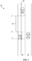
- FIG. 5 is a diagram illustrating an overview of a traffic environment, including vehicles on highway lanes and a controlled ego vehicle prior to a lane change, according to aspects of the present disclosure.
- the traffic environment includes a multilane highway 500 (e.g., a two lane highway), having a first lane 502 and a target lane 504 (e.g., a second lane), in which the first lane 502 includes a controlled ego vehicle 550 .
- the controlled ego vehicle 550 is configured to monitor the dynamics of vehicles on the multilane highway 500 , such as a first vehicle 510 and a second vehicle 520 in the target lane 504 of the multilane highway 500 .
- the controlled ego vehicle 550 desired to change lanes from the first lane 502 to the target lane 504 of the multilane highway 500 .
- the controlled ego vehicle 550 may be the car 350 , shown in FIG. 3 .
- the controlled ego vehicle 550 is controlled by a vehicle controller (e.g., the vehicle behavior controller 310 ).
- the controlled ego vehicle 550 e.g., the vehicle perception module 314 ) identifies a merge gap 530 between the first vehicle 510 and the second vehicle 520 in the target lane 504 . That is, the controlled ego vehicle 550 is configured to identify the merge gap 530 to enable a lane change of the controlled ego vehicle 550 from the first lane 502 to the target lane 504 .
- the controlled ego vehicle 550 is configured to compute an exposure time in which the controlled ego vehicle 550 is specified to merge into the merge gap 530 .
- an S-axis 540 indicates a position along the target lane 504 of the multilane highway 500 .
- the controlled ego vehicle 550 is shown at a position S e .
- the position S e can change with time “t” so it becomes a function S e (t).
- the first vehicle 510 e.g., rear obstacle
- the second vehicle 520 e.g., front obstacle
- the positions S r and S f can be chosen to incorporate a predetermined amount of padding distance to account for the safe driving distance and the length of the controlled ego vehicle 550 .
- an exposure interval is defined as an interval [T s , T e ] (e.g., start and end times).
- the exposure interval is defined, such that a position of the controlled ego vehicle 550 is between the first vehicle 510 (e.g., rear vehicle) and the second vehicle 520 (e.g., front vehicle), formally: t e >t s ⁇ s r ( t ) ⁇ s e ( t ) ⁇ s f ( t ), ⁇ t ⁇ [ t s ,t e ] (1)
- the exposure time “E” is simply the length of the exposure interval (e.g., T e ⁇ T s ).
- a speed profile of the controlled ego vehicle 550 is controlled and adjustable, control is also provided over the function S e (t).
- a set of safe and comfortable acceleration/braking profiles “A” are defined.
- variations of an exposure time are computed based on application of different acceleration/braking values.
- the controlled ego vehicle 550 is configured to perform vehicle control actions to maximize the exposure time E according to Equation (2). Maximizing the exposure time increases the probability of a successful lane change within the multilane highway 500 .
- the vehicle controller e.g., vehicle control selection module 318 . adjusts an acceleration/braking of the controlled ego vehicle 550 to efficiently and smoothly merge from the first lane 502 to the target lane 504 .
- a target acceleration/braking value of the controlled ego vehicle 550 is not safe, the vehicle controller ignores the target acceleration/braking value and selects a different merge gap. Therefore, a collision avoidance function is provided by the vehicle controller (e.g., vehicle behavior controller 310 ).
- FIG. 6 is a flowchart illustrating a method of improving a merging efficiency of an ego vehicle, according to aspects of the present disclosure.
- a method 600 begins at block 602 , in which one or more merge gaps are determined between vehicles in a target lane of a multilane highway.
- the controlled ego vehicle 550 identifies a merge gap 530 between the first vehicle 510 and the second vehicle 520 in the target lane 504 . That is, the controlled ego vehicle 550 is configured to identify the merge gap 530 to enable a lane change of the controlled ego vehicle 550 from the first lane 502 to the target lane 504 .
- an exposure time in which an ego vehicle is specified to merge into the one or merge gaps is computed.
- the controlled ego vehicle 550 is configured to compute an exposure time in which the controlled ego vehicle 550 is specified to merge into the merge gap 530 .
- the exposure interval is defined, such that a position of the controlled ego vehicle 550 is between the first vehicle 510 (e.g., rear vehicle) and the second vehicle (e.g., front vehicle).
- a merge gap is selected between a first vehicle and a second vehicle the target lane of the multilane highway having a maximum exposure time.
- This process includes adjusting a selected acceleration/braking value of the ego vehicle for each of the one or more merge gaps to maximize the exposure time for each of the one or more merge gaps. This process further includes selecting a merge gap from the one or more merge gaps according to a corresponding exposure time.
- a vehicle control action is selected to merge the ego vehicle into the merge gap between the first vehicle and the second vehicle in the target lane.
- the controlled ego vehicle 550 is configured to vary vehicle control actions to maximize the exposure time E according to Equation (2).
- the vehicle controller e.g., vehicle control selection module 318
- the selecting of the merge gap in block 606 may also include discarding a merge gap from the one or more merge gaps if a trigger time to initiate merging into the discarded merge gap is greater than a predetermined value (e.g., ten seconds). Alternatively, if the exposure time “E” is less than a predetermined threshold value four seconds) a is merge gap is discarded from the one or more merge gaps.
- a predetermined value e.g., ten seconds
- the method shown in FIG. 6 may be performed by the SOC 100 ( FIG. 1 ) or the software architecture 200 ( FIG. 2 ) of the autonomous vehicle 150 . That is, each of the elements or methods may, for example, but without limitation, be performed by the SOC 100 , the software architecture 200 , the processor (e.g., CPU 102 ) and/or other components included therein of the autonomous vehicle 150 , or the vehicle behavior control system 300 .
- the various operations of methods described above may be performed by any suitable means capable of performing the corresponding functions.
- the means may include various hardware and/or software component(s) and/or module(s), including, but not limited to, a circuit, an application specific integrated circuit (ASIC), or processor.
- ASIC application specific integrated circuit
- determining encompasses a wide variety of actions. For example, “determining” may include calculating, computing, processing, deriving, investigating, looking up (e.g., looking up in a table, a database or another data structure), ascertaining, and the like. Additionally, “determining” may include receiving (e.g., receiving information), accessing (e.g., accessing data in a memory), and the like. Furthermore, “determining” may include resolving, selecting, choosing, establishing, and the like.
- a phrase referring to “at least one of” a list of items refers to any combination of those items, including single members.
- “at least one of: a, b, or c” is intended to cover: a, b, c, a-b, a-c, b-c, and a-b-c.
- DSP digital signal processor
- ASIC application specific integrated circuit
- FPGA field programmable gate array signal
- PLD programmable logic device
- the processor may be a microprocessor, but, in the alternative, the processor may be any commercially available processor, controller, microcontroller, or state machine specially configured as described herein.
- a processor may also be implemented as a combination of computing devices, e.g., a combination of a DSP and a microprocessor, a plurality of microprocessors, one or more microprocessors in conjunction with a DSP core, or any other such configuration.
- a software module may reside in any form of storage medium that is known in the art. Some examples of storage media that may be used include random access memory (RAM), read only memory (ROM), flash memory, erasable programmable read-only memory (EPROM), electrically erasable programmable read-only memory (EEPROM), registers, a hard disk, a removable disk, a CD-ROM, and so forth.
- RAM random access memory
- ROM read only memory
- EPROM erasable programmable read-only memory
- EEPROM electrically erasable programmable read-only memory
- registers a hard disk, a removable disk, a CD-ROM, and so forth.
- a software module may comprise a single instruction, or many instructions, and may be distributed over several different code segments, among different programs, and across multiple storage media.
- a storage medium may be coupled to a processor such that the processor can read information from, and write information to, the storage medium. In the alternative, the storage medium may be integral to the processor.
- the methods disclosed herein comprise one or more steps or actions for achieving the described method.
- the method steps and/or actions may be interchanged with one another without departing from the scope of the claims.
- the order and/or use of specific steps and/or actions may be modified without departing from the scope of the claims.
- an example hardware configuration may comprise a processing system in a device.
- the processing system may be implemented with a bus architecture.
- the bus may include any number of interconnecting buses and bridges depending on the specific application of the processing system and the overall design constraints.
- the bus may link together various circuits including a processor, machine-readable media, and a bus interface.
- the bus interface may connect a network adapter, among other things, to the processing system via the bus.
- the network adapter may implement signal processing functions.
- a user interface e.g., keypad, display, mouse, joystick, etc.
- the bus may also link various other circuits such as timing sources, peripherals, voltage regulators, power management circuits, and the like, which are well known in the art, and therefore, will not be described any further.
- the processor may be responsible for managing the bus and processing, including the execution of software stored on the machine-readable media.
- Examples of processors that may be specially configured according to the present disclosure include microprocessors, microcontrollers, DSP processors, and other circuitry that can execute software.
- Software shall be construed broadly to mean instructions, data, or any combination thereof, whether referred to as software, firmware, middleware, microcode, hardware description language, or otherwise.
- Machine-readable media may include, by way of example, random access memory (RAM), flash memory, read only memory (ROM), programmable read-only memory (PROM), erasable programmable read-only memory (EPROM), electrically erasable programmable read-only memory (EEPROM), registers, magnetic disks, optical disks, hard drives, or any other suitable storage medium, or any combination thereof.
- RAM random access memory
- ROM read only memory
- PROM programmable read-only memory
- EPROM erasable programmable read-only memory
- EEPROM electrically erasable programmable read-only memory
- registers magnetic disks, optical disks, hard drives, or any other suitable storage medium, or any combination thereof.
- the machine-readable media may be embodied in a computer-program product.
- the computer-program product may comprise packaging materials.
- the machine-readable media may be part of the processing system separate from the processor.
- the machine-readable media, or any portion thereof may be external to the processing system.
- the machine-readable media may include a transmission line, a carrier wave modulated by data, and/or a computer product separate from the device, all which may be accessed by the processor through the bus interface.
- the machine-readable media, or any portion thereof may be integrated into the processor, such as the case may be with cache and/or specialized register files.
- the various components discussed may be described as having a specific location, such as a local component, they may also be configured in various ways, such as certain components being configured as part of a distributed computing system.
- the processing system may be configured with one or more microprocessors providing the processor functionality and external memory providing at least a portion of the machine-readable media, all linked together with other supporting circuitry through an external bus architecture.
- the processing system may comprise one or more neuromorphic processors for implementing the neuron models and models of neural systems described herein.
- the processing system may be implemented with an application specific integrated circuit (ASIC) with the processor, the bus interface, the user interface, supporting circuitry, and at least a portion of the machine-readable media integrated into a single chip, or with one or more field programmable gate arrays (FPGAs), programmable logic devices (PLDs), controllers, state machines, gated logic, discrete hardware components, or any other suitable circuitry, or any combination of circuits that can perform the various functions described throughout the present disclosure.
- ASIC application specific integrated circuit
- FPGAs field programmable gate arrays
- PLDs programmable logic devices
- controllers state machines, gated logic, discrete hardware components, or any other suitable circuitry, or any combination of circuits that can perform the various functions described throughout the present disclosure.
- the machine-readable media may comprise a number of software modules.
- the software modules include instructions that, when executed by the processor, cause the processing system to perform various functions.
- the software modules may include a transmission module and a receiving module.
- Each software module may reside in a single storage device or be distributed across multiple storage devices.
- a software module may be loaded into RAM from a hard drive when a triggering event occurs.
- the processor may load some of the instructions into cache to increase access speed.
- One or more cache lines may then be loaded into a special purpose register file for execution by the processor.
- Computer-readable media include both computer storage media and communication media including any medium that facilitates transfer of a computer program from one place to another.
- a storage medium may be any available medium that can be accessed by a computer.
- such computer-readable media can comprise RAM, ROM, EEPROM, CD-ROM or other optical disk storage, magnetic disk storage or other magnetic storage devices, or any other medium that can carry or store desired program code in the form of instructions or data structures and that can be accessed by a computer. Additionally, any connection is properly termed a computer-readable medium.
- Disk and disc include compact disc (CD), laser disc, optical disc, digital versatile disc (DVD), floppy disk, and Blu-ray® disc, where disks usually reproduce data magnetically, while discs reproduce data optically with lasers.
- computer-readable media may comprise non-transitory computer-readable media (e.g., tangible media).
- computer-readable media may comprise transitory computer-readable media (e.g., a signal). Combinations of the above should also be included within the scope of computer-readable media.
- certain aspects may comprise a computer program product for performing the operations presented herein.
- a computer program product may comprise a computer-readable medium having instructions stored (and/or encoded) thereon, the instructions being executable by one or more processors to perform the operations described herein.
- the computer program product may include packaging material.
- modules and/or other appropriate means for performing the methods and techniques described herein can be downloaded and/or otherwise obtained by a user terminal and/or base station as applicable.
- a user terminal and/or base station can be coupled to a server to facilitate the transfer of means for performing the methods described herein.
- various methods described herein can be provided via storage means (e.g., RAM, ROM, a physical storage medium such as a compact disc (CD) or floppy disk, etc.), such that a user terminal and/or base station can obtain the various methods upon coupling or providing the storage means to the device.
- storage means e.g., RAM, ROM, a physical storage medium such as a compact disc (CD) or floppy disk, etc.
- CD compact disc
- floppy disk etc.
- any other suitable technique for providing the methods and techniques described herein to a device can be utilized.
Landscapes
- Engineering & Computer Science (AREA)
- Automation & Control Theory (AREA)
- Transportation (AREA)
- Mechanical Engineering (AREA)
- Computer Networks & Wireless Communication (AREA)
- Signal Processing (AREA)
- Human Computer Interaction (AREA)
- Traffic Control Systems (AREA)
Abstract
Description
t e >t s ∧s r(t)≤s e(t)≤s f(t),∀t∈[t s ,t e] (1)
In addition, the exposure time “E” is simply the length of the exposure interval (e.g., Te−Ts). Because a speed profile of the controlled
E=maxa∈A(t e −t s),s.t.t e >t s s r(t)≤s e(t,a)≤s f(t),∀t∈[t s ,t e] (2)
Claims (17)
Priority Applications (1)
| Application Number | Priority Date | Filing Date | Title |
|---|---|---|---|
| US16/888,330 US11511751B2 (en) | 2020-05-29 | 2020-05-29 | Merge situation exposure algorithms to maximize exposure time |
Applications Claiming Priority (1)
| Application Number | Priority Date | Filing Date | Title |
|---|---|---|---|
| US16/888,330 US11511751B2 (en) | 2020-05-29 | 2020-05-29 | Merge situation exposure algorithms to maximize exposure time |
Publications (2)
| Publication Number | Publication Date |
|---|---|
| US20210370945A1 US20210370945A1 (en) | 2021-12-02 |
| US11511751B2 true US11511751B2 (en) | 2022-11-29 |
Family
ID=78706632
Family Applications (1)
| Application Number | Title | Priority Date | Filing Date |
|---|---|---|---|
| US16/888,330 Active 2041-03-13 US11511751B2 (en) | 2020-05-29 | 2020-05-29 | Merge situation exposure algorithms to maximize exposure time |
Country Status (1)
| Country | Link |
|---|---|
| US (1) | US11511751B2 (en) |
Families Citing this family (1)
| Publication number | Priority date | Publication date | Assignee | Title |
|---|---|---|---|---|
| US20240063651A1 (en) * | 2022-08-16 | 2024-02-22 | Microsoft Technology Licensing, Llc | Controlling electrical power flowing from a battery |
Citations (19)
| Publication number | Priority date | Publication date | Assignee | Title |
|---|---|---|---|---|
| US5761630A (en) | 1995-03-23 | 1998-06-02 | Honda Giken Kogyo Kabushiki Kaisha | Vehicle control system for merging vehicles safely |
| US20050015203A1 (en) | 2003-07-18 | 2005-01-20 | Nissan Motor Co., Ltd. | Lane-changing support system |
| US20090060647A1 (en) | 2007-09-04 | 2009-03-05 | John Denison | Traffic merging system |
| US20140074356A1 (en) * | 2011-05-20 | 2014-03-13 | Honda Motor Co., Ltd. | Lane change assist system |
| US8810431B2 (en) | 2011-10-20 | 2014-08-19 | GM Global Technology Operations LLC | Highway merge assistant and control |
| US9159023B2 (en) | 2010-06-18 | 2015-10-13 | Honda Motor Co., Ltd. | System for predicting a driver's intention to change lanes |
| JP2016007954A (en) * | 2014-06-25 | 2016-01-18 | トヨタ自動車株式会社 | Lane merging assist system |
| US20170174261A1 (en) * | 2015-12-17 | 2017-06-22 | Ford Global Technologies, Llc | Vehicle Turn Signal Detection |
| US20170197626A1 (en) * | 2016-01-11 | 2017-07-13 | Ford Global Technologies, Llc | Management of autonomous vehicle lanes |
| EP2499459B1 (en) | 2009-11-12 | 2018-12-26 | TomTom Belgium N.V. | Navigation system with live speed warning for merging traffic flow |
| US10317902B2 (en) | 2016-02-22 | 2019-06-11 | Volvo Car Corporation | Method and system for evaluating inter-vehicle traffic gaps and time instances to perform a lane change maneuver |
| US20190193737A1 (en) * | 2017-12-21 | 2019-06-27 | Denso International America, Inc. | System For Autonomous Lane Merging |
| US20190299983A1 (en) | 2016-12-23 | 2019-10-03 | Mobileye Vision Technologies Ltd. | Safe State to Safe State Navigation |
| US20190311616A1 (en) * | 2018-04-10 | 2019-10-10 | Cavh Llc | Connected and automated vehicle systems and methods for the entire roadway network |
| US20190329778A1 (en) | 2018-04-27 | 2019-10-31 | Honda Motor Co., Ltd. | Merge behavior systems and methods for merging vehicles |
| US20200286386A1 (en) * | 2017-10-25 | 2020-09-10 | Huawei Technologies Co., Ltd. | Vehicle Merging Method and Apparatus |
| US20210001857A1 (en) * | 2019-07-03 | 2021-01-07 | Toyota Motor Engineering & Manufacturing North America, Inc. | Efficiency improvement for machine learning of vehicle control using traffic state estimation |
| US20210229656A1 (en) * | 2019-10-24 | 2021-07-29 | Zoox, Inc. | Trajectory modifications based on a collision zone |
| US20220089164A1 (en) * | 2020-09-24 | 2022-03-24 | Toyota Motor Engineering & Manufacturing North America, Inc. | System and method for connected vehicle lane merge |
-
2020
- 2020-05-29 US US16/888,330 patent/US11511751B2/en active Active
Patent Citations (19)
| Publication number | Priority date | Publication date | Assignee | Title |
|---|---|---|---|---|
| US5761630A (en) | 1995-03-23 | 1998-06-02 | Honda Giken Kogyo Kabushiki Kaisha | Vehicle control system for merging vehicles safely |
| US20050015203A1 (en) | 2003-07-18 | 2005-01-20 | Nissan Motor Co., Ltd. | Lane-changing support system |
| US20090060647A1 (en) | 2007-09-04 | 2009-03-05 | John Denison | Traffic merging system |
| EP2499459B1 (en) | 2009-11-12 | 2018-12-26 | TomTom Belgium N.V. | Navigation system with live speed warning for merging traffic flow |
| US9159023B2 (en) | 2010-06-18 | 2015-10-13 | Honda Motor Co., Ltd. | System for predicting a driver's intention to change lanes |
| US20140074356A1 (en) * | 2011-05-20 | 2014-03-13 | Honda Motor Co., Ltd. | Lane change assist system |
| US8810431B2 (en) | 2011-10-20 | 2014-08-19 | GM Global Technology Operations LLC | Highway merge assistant and control |
| JP2016007954A (en) * | 2014-06-25 | 2016-01-18 | トヨタ自動車株式会社 | Lane merging assist system |
| US20170174261A1 (en) * | 2015-12-17 | 2017-06-22 | Ford Global Technologies, Llc | Vehicle Turn Signal Detection |
| US20170197626A1 (en) * | 2016-01-11 | 2017-07-13 | Ford Global Technologies, Llc | Management of autonomous vehicle lanes |
| US10317902B2 (en) | 2016-02-22 | 2019-06-11 | Volvo Car Corporation | Method and system for evaluating inter-vehicle traffic gaps and time instances to perform a lane change maneuver |
| US20190299983A1 (en) | 2016-12-23 | 2019-10-03 | Mobileye Vision Technologies Ltd. | Safe State to Safe State Navigation |
| US20200286386A1 (en) * | 2017-10-25 | 2020-09-10 | Huawei Technologies Co., Ltd. | Vehicle Merging Method and Apparatus |
| US20190193737A1 (en) * | 2017-12-21 | 2019-06-27 | Denso International America, Inc. | System For Autonomous Lane Merging |
| US20190311616A1 (en) * | 2018-04-10 | 2019-10-10 | Cavh Llc | Connected and automated vehicle systems and methods for the entire roadway network |
| US20190329778A1 (en) | 2018-04-27 | 2019-10-31 | Honda Motor Co., Ltd. | Merge behavior systems and methods for merging vehicles |
| US20210001857A1 (en) * | 2019-07-03 | 2021-01-07 | Toyota Motor Engineering & Manufacturing North America, Inc. | Efficiency improvement for machine learning of vehicle control using traffic state estimation |
| US20210229656A1 (en) * | 2019-10-24 | 2021-07-29 | Zoox, Inc. | Trajectory modifications based on a collision zone |
| US20220089164A1 (en) * | 2020-09-24 | 2022-03-24 | Toyota Motor Engineering & Manufacturing North America, Inc. | System and method for connected vehicle lane merge |
Non-Patent Citations (1)
| Title |
|---|
| Kang, K, et al., "A Repeated Game Freeway Lane Changing Model." Sensors (Basel, Switzerland) vol. 20(6), pp. 1554, Mar. 11, 2020. |
Also Published As
| Publication number | Publication date |
|---|---|
| US20210370945A1 (en) | 2021-12-02 |
Similar Documents
| Publication | Publication Date | Title |
|---|---|---|
| US20240425084A1 (en) | Navigation cost computation for lane changes before a critical intersection | |
| US11279361B2 (en) | Efficiency improvement for machine learning of vehicle control using traffic state estimation | |
| US11644835B2 (en) | Game-theoretic planning for risk-aware interactive agents | |
| US12249193B2 (en) | Partial sensor data sharing for connected vehicles | |
| US11702138B2 (en) | Method for lateral control assistance to enable one-handed driving of a vehicle | |
| US11735051B2 (en) | Detection of bicyclists near ego vehicles | |
| US11854280B2 (en) | Learning monocular 3D object detection from 2D semantic keypoint detection | |
| US20220068050A1 (en) | System and method for monitoring test data for autonomous operation of self-driving vehicles | |
| US20240363000A1 (en) | Traffic signal understandings and representation for prediction, planning, and control | |
| US11531842B2 (en) | Invertible depth network for image reconstruction and domain transfers | |
| US20230347925A1 (en) | Agent and scenario modeling extracted via an mbse classification on a large number of real-world data samples | |
| US11703870B2 (en) | Method for computing maneuvers drivable space using piecewise semantic aggregation of trajectories | |
| US12159465B2 (en) | End-to-end learned lane boundary detection based on a transformer | |
| US11935258B2 (en) | Range detection using machine learning combined with camera focus | |
| US11511751B2 (en) | Merge situation exposure algorithms to maximize exposure time | |
| US12158925B2 (en) | Learning-based online mapping | |
| US12391279B2 (en) | Method for enumerating homotopies for maneuvers using a hierarchy of tolerance relations | |
| US20240246552A1 (en) | Method for overriding disablement of advanced driver assistance system (adas) safety features based on driver impairment and driver performance | |
| US11687155B2 (en) | Method for vehicle eye tracking system | |
| US12071172B2 (en) | Method for visualizing a steering angle and lateral boundaries for driver assist and safer driving | |
| US20230294742A1 (en) | System and method for lane association/transition association with splines | |
| US12488597B2 (en) | End-to-end monocular 2D semantic keypoint detector and tracker learning | |
| US20230056475A1 (en) | System and method for a scenario-based event trigger | |
| US12122421B2 (en) | Method for improving temporal consistency of planned maneuvers | |
| US12576881B2 (en) | Method for polynomial based predictions of ego vehicles and adversarial agents |
Legal Events
| Date | Code | Title | Description |
|---|---|---|---|
| FEPP | Fee payment procedure |
Free format text: ENTITY STATUS SET TO UNDISCOUNTED (ORIGINAL EVENT CODE: BIG.); ENTITY STATUS OF PATENT OWNER: LARGE ENTITY |
|
| AS | Assignment |
Owner name: TOYOTA RESEARCH INSTITUTE, INC., CALIFORNIA Free format text: ASSIGNMENT OF ASSIGNORS INTEREST;ASSIGNOR:MOLINARI, DANIELE;REEL/FRAME:052849/0668 Effective date: 20200513 |
|
| STPP | Information on status: patent application and granting procedure in general |
Free format text: NON FINAL ACTION MAILED |
|
| STPP | Information on status: patent application and granting procedure in general |
Free format text: RESPONSE TO NON-FINAL OFFICE ACTION ENTERED AND FORWARDED TO EXAMINER |
|
| STPP | Information on status: patent application and granting procedure in general |
Free format text: NOTICE OF ALLOWANCE MAILED -- APPLICATION RECEIVED IN OFFICE OF PUBLICATIONS |
|
| STPP | Information on status: patent application and granting procedure in general |
Free format text: PUBLICATIONS -- ISSUE FEE PAYMENT VERIFIED |
|
| STCF | Information on status: patent grant |
Free format text: PATENTED CASE |
|
| AS | Assignment |
Owner name: TOYOTA JIDOSHA KABUSHIKI KAISHA, JAPAN Free format text: ASSIGNMENT OF ASSIGNORS INTEREST;ASSIGNOR:TOYOTA RESEARCH INSTITUTE, INC.;REEL/FRAME:063736/0115 Effective date: 20230516 |