EP3208693A2 - Ensemble de dispositif périphérique modulaire - Google Patents
Ensemble de dispositif périphérique modulaire Download PDFInfo
- Publication number
- EP3208693A2 EP3208693A2 EP17156497.4A EP17156497A EP3208693A2 EP 3208693 A2 EP3208693 A2 EP 3208693A2 EP 17156497 A EP17156497 A EP 17156497A EP 3208693 A2 EP3208693 A2 EP 3208693A2
- Authority
- EP
- European Patent Office
- Prior art keywords
- handheld controller
- assembly base
- assembly
- magnet
- haptic
- Prior art date
- Legal status (The legal status is an assumption and is not a legal conclusion. Google has not performed a legal analysis and makes no representation as to the accuracy of the status listed.)
- Withdrawn
Links
Images


Classifications
-
- G—PHYSICS
- G06—COMPUTING; CALCULATING OR COUNTING
- G06F—ELECTRIC DIGITAL DATA PROCESSING
- G06F3/00—Input arrangements for transferring data to be processed into a form capable of being handled by the computer; Output arrangements for transferring data from processing unit to output unit, e.g. interface arrangements
- G06F3/01—Input arrangements or combined input and output arrangements for interaction between user and computer
- G06F3/016—Input arrangements with force or tactile feedback as computer generated output to the user
-
- A—HUMAN NECESSITIES
- A63—SPORTS; GAMES; AMUSEMENTS
- A63F—CARD, BOARD, OR ROULETTE GAMES; INDOOR GAMES USING SMALL MOVING PLAYING BODIES; VIDEO GAMES; GAMES NOT OTHERWISE PROVIDED FOR
- A63F13/00—Video games, i.e. games using an electronically generated display having two or more dimensions
- A63F13/20—Input arrangements for video game devices
- A63F13/21—Input arrangements for video game devices characterised by their sensors, purposes or types
- A63F13/211—Input arrangements for video game devices characterised by their sensors, purposes or types using inertial sensors, e.g. accelerometers or gyroscopes
-
- A—HUMAN NECESSITIES
- A63—SPORTS; GAMES; AMUSEMENTS
- A63F—CARD, BOARD, OR ROULETTE GAMES; INDOOR GAMES USING SMALL MOVING PLAYING BODIES; VIDEO GAMES; GAMES NOT OTHERWISE PROVIDED FOR
- A63F13/00—Video games, i.e. games using an electronically generated display having two or more dimensions
- A63F13/20—Input arrangements for video game devices
- A63F13/24—Constructional details thereof, e.g. game controllers with detachable joystick handles
-
- A—HUMAN NECESSITIES
- A63—SPORTS; GAMES; AMUSEMENTS
- A63F—CARD, BOARD, OR ROULETTE GAMES; INDOOR GAMES USING SMALL MOVING PLAYING BODIES; VIDEO GAMES; GAMES NOT OTHERWISE PROVIDED FOR
- A63F13/00—Video games, i.e. games using an electronically generated display having two or more dimensions
- A63F13/25—Output arrangements for video game devices
- A63F13/28—Output arrangements for video game devices responding to control signals received from the game device for affecting ambient conditions, e.g. for vibrating players' seats, activating scent dispensers or affecting temperature or light
- A63F13/285—Generating tactile feedback signals via the game input device, e.g. force feedback
-
- A—HUMAN NECESSITIES
- A63—SPORTS; GAMES; AMUSEMENTS
- A63F—CARD, BOARD, OR ROULETTE GAMES; INDOOR GAMES USING SMALL MOVING PLAYING BODIES; VIDEO GAMES; GAMES NOT OTHERWISE PROVIDED FOR
- A63F13/00—Video games, i.e. games using an electronically generated display having two or more dimensions
- A63F13/90—Constructional details or arrangements of video game devices not provided for in groups A63F13/20 or A63F13/25, e.g. housing, wiring, connections or cabinets
- A63F13/98—Accessories, i.e. detachable arrangements optional for the use of the video game device, e.g. grip supports of game controllers
-
- G—PHYSICS
- G05—CONTROLLING; REGULATING
- G05G—CONTROL DEVICES OR SYSTEMS INSOFAR AS CHARACTERISED BY MECHANICAL FEATURES ONLY
- G05G9/00—Manually-actuated control mechanisms provided with one single controlling member co-operating with two or more controlled members, e.g. selectively, simultaneously
- G05G9/02—Manually-actuated control mechanisms provided with one single controlling member co-operating with two or more controlled members, e.g. selectively, simultaneously the controlling member being movable in different independent ways, movement in each individual way actuating one controlled member only
- G05G9/04—Manually-actuated control mechanisms provided with one single controlling member co-operating with two or more controlled members, e.g. selectively, simultaneously the controlling member being movable in different independent ways, movement in each individual way actuating one controlled member only in which movement in two or more ways can occur simultaneously
- G05G9/047—Manually-actuated control mechanisms provided with one single controlling member co-operating with two or more controlled members, e.g. selectively, simultaneously the controlling member being movable in different independent ways, movement in each individual way actuating one controlled member only in which movement in two or more ways can occur simultaneously the controlling member being movable by hand about orthogonal axes, e.g. joysticks
-
- G—PHYSICS
- G06—COMPUTING; CALCULATING OR COUNTING
- G06F—ELECTRIC DIGITAL DATA PROCESSING
- G06F3/00—Input arrangements for transferring data to be processed into a form capable of being handled by the computer; Output arrangements for transferring data from processing unit to output unit, e.g. interface arrangements
- G06F3/01—Input arrangements or combined input and output arrangements for interaction between user and computer
- G06F3/011—Arrangements for interaction with the human body, e.g. for user immersion in virtual reality
-
- G—PHYSICS
- G06—COMPUTING; CALCULATING OR COUNTING
- G06F—ELECTRIC DIGITAL DATA PROCESSING
- G06F3/00—Input arrangements for transferring data to be processed into a form capable of being handled by the computer; Output arrangements for transferring data from processing unit to output unit, e.g. interface arrangements
- G06F3/01—Input arrangements or combined input and output arrangements for interaction between user and computer
- G06F3/03—Arrangements for converting the position or the displacement of a member into a coded form
- G06F3/033—Pointing devices displaced or positioned by the user, e.g. mice, trackballs, pens or joysticks; Accessories therefor
- G06F3/0338—Pointing devices displaced or positioned by the user, e.g. mice, trackballs, pens or joysticks; Accessories therefor with detection of limited linear or angular displacement of an operating part of the device from a neutral position, e.g. isotonic or isometric joysticks
-
- G—PHYSICS
- G06—COMPUTING; CALCULATING OR COUNTING
- G06F—ELECTRIC DIGITAL DATA PROCESSING
- G06F3/00—Input arrangements for transferring data to be processed into a form capable of being handled by the computer; Output arrangements for transferring data from processing unit to output unit, e.g. interface arrangements
- G06F3/01—Input arrangements or combined input and output arrangements for interaction between user and computer
- G06F3/03—Arrangements for converting the position or the displacement of a member into a coded form
- G06F3/033—Pointing devices displaced or positioned by the user, e.g. mice, trackballs, pens or joysticks; Accessories therefor
- G06F3/0346—Pointing devices displaced or positioned by the user, e.g. mice, trackballs, pens or joysticks; Accessories therefor with detection of the device orientation or free movement in a 3D space, e.g. 3D mice, 6-DOF [six degrees of freedom] pointers using gyroscopes, accelerometers or tilt-sensors
-
- G—PHYSICS
- G06—COMPUTING; CALCULATING OR COUNTING
- G06T—IMAGE DATA PROCESSING OR GENERATION, IN GENERAL
- G06T19/00—Manipulating 3D models or images for computer graphics
- G06T19/006—Mixed reality
-
- A—HUMAN NECESSITIES
- A63—SPORTS; GAMES; AMUSEMENTS
- A63F—CARD, BOARD, OR ROULETTE GAMES; INDOOR GAMES USING SMALL MOVING PLAYING BODIES; VIDEO GAMES; GAMES NOT OTHERWISE PROVIDED FOR
- A63F13/00—Video games, i.e. games using an electronically generated display having two or more dimensions
- A63F13/40—Processing input control signals of video game devices, e.g. signals generated by the player or derived from the environment
- A63F13/42—Processing input control signals of video game devices, e.g. signals generated by the player or derived from the environment by mapping the input signals into game commands, e.g. mapping the displacement of a stylus on a touch screen to the steering angle of a virtual vehicle
- A63F13/428—Processing input control signals of video game devices, e.g. signals generated by the player or derived from the environment by mapping the input signals into game commands, e.g. mapping the displacement of a stylus on a touch screen to the steering angle of a virtual vehicle involving motion or position input signals, e.g. signals representing the rotation of an input controller or a player's arm motions sensed by accelerometers or gyroscopes
-
- A—HUMAN NECESSITIES
- A63—SPORTS; GAMES; AMUSEMENTS
- A63F—CARD, BOARD, OR ROULETTE GAMES; INDOOR GAMES USING SMALL MOVING PLAYING BODIES; VIDEO GAMES; GAMES NOT OTHERWISE PROVIDED FOR
- A63F13/00—Video games, i.e. games using an electronically generated display having two or more dimensions
- A63F13/90—Constructional details or arrangements of video game devices not provided for in groups A63F13/20 or A63F13/25, e.g. housing, wiring, connections or cabinets
- A63F13/92—Video game devices specially adapted to be hand-held while playing
-
- A—HUMAN NECESSITIES
- A63—SPORTS; GAMES; AMUSEMENTS
- A63F—CARD, BOARD, OR ROULETTE GAMES; INDOOR GAMES USING SMALL MOVING PLAYING BODIES; VIDEO GAMES; GAMES NOT OTHERWISE PROVIDED FOR
- A63F2250/00—Miscellaneous game characteristics
- A63F2250/12—Miscellaneous game characteristics using a string, rope, strap or belt as a play element
- A63F2250/121—Strap or belt
-
- A—HUMAN NECESSITIES
- A63—SPORTS; GAMES; AMUSEMENTS
- A63F—CARD, BOARD, OR ROULETTE GAMES; INDOOR GAMES USING SMALL MOVING PLAYING BODIES; VIDEO GAMES; GAMES NOT OTHERWISE PROVIDED FOR
- A63F2250/00—Miscellaneous game characteristics
- A63F2250/52—Miscellaneous game characteristics with a remote control
-
- A—HUMAN NECESSITIES
- A63—SPORTS; GAMES; AMUSEMENTS
- A63F—CARD, BOARD, OR ROULETTE GAMES; INDOOR GAMES USING SMALL MOVING PLAYING BODIES; VIDEO GAMES; GAMES NOT OTHERWISE PROVIDED FOR
- A63F2300/00—Features of games using an electronically generated display having two or more dimensions, e.g. on a television screen, showing representations related to the game
- A63F2300/10—Features of games using an electronically generated display having two or more dimensions, e.g. on a television screen, showing representations related to the game characterized by input arrangements for converting player-generated signals into game device control signals
- A63F2300/1037—Features of games using an electronically generated display having two or more dimensions, e.g. on a television screen, showing representations related to the game characterized by input arrangements for converting player-generated signals into game device control signals being specially adapted for converting control signals received from the game device into a haptic signal, e.g. using force feedback
-
- A—HUMAN NECESSITIES
- A63—SPORTS; GAMES; AMUSEMENTS
- A63F—CARD, BOARD, OR ROULETTE GAMES; INDOOR GAMES USING SMALL MOVING PLAYING BODIES; VIDEO GAMES; GAMES NOT OTHERWISE PROVIDED FOR
- A63F2300/00—Features of games using an electronically generated display having two or more dimensions, e.g. on a television screen, showing representations related to the game
- A63F2300/80—Features of games using an electronically generated display having two or more dimensions, e.g. on a television screen, showing representations related to the game specially adapted for executing a specific type of game
- A63F2300/8082—Virtual reality
-
- G—PHYSICS
- G05—CONTROLLING; REGULATING
- G05G—CONTROL DEVICES OR SYSTEMS INSOFAR AS CHARACTERISED BY MECHANICAL FEATURES ONLY
- G05G9/00—Manually-actuated control mechanisms provided with one single controlling member co-operating with two or more controlled members, e.g. selectively, simultaneously
- G05G9/02—Manually-actuated control mechanisms provided with one single controlling member co-operating with two or more controlled members, e.g. selectively, simultaneously the controlling member being movable in different independent ways, movement in each individual way actuating one controlled member only
- G05G9/04—Manually-actuated control mechanisms provided with one single controlling member co-operating with two or more controlled members, e.g. selectively, simultaneously the controlling member being movable in different independent ways, movement in each individual way actuating one controlled member only in which movement in two or more ways can occur simultaneously
- G05G9/047—Manually-actuated control mechanisms provided with one single controlling member co-operating with two or more controlled members, e.g. selectively, simultaneously the controlling member being movable in different independent ways, movement in each individual way actuating one controlled member only in which movement in two or more ways can occur simultaneously the controlling member being movable by hand about orthogonal axes, e.g. joysticks
- G05G2009/04703—Mounting of controlling member
- G05G2009/04714—Mounting of controlling member with orthogonal axes
- G05G2009/04718—Mounting of controlling member with orthogonal axes with cardan or gimbal type joint
-
- G—PHYSICS
- G06—COMPUTING; CALCULATING OR COUNTING
- G06F—ELECTRIC DIGITAL DATA PROCESSING
- G06F2203/00—Indexing scheme relating to G06F3/00 - G06F3/048
- G06F2203/01—Indexing scheme relating to G06F3/01
- G06F2203/013—Force feedback applied to a game
-
- G—PHYSICS
- G06—COMPUTING; CALCULATING OR COUNTING
- G06F—ELECTRIC DIGITAL DATA PROCESSING
- G06F2203/00—Indexing scheme relating to G06F3/00 - G06F3/048
- G06F2203/01—Indexing scheme relating to G06F3/01
- G06F2203/015—Force feedback applied to a joystick
Definitions
- the present invention is directed to a modular peripheral device assembly that has application in user interfaces, gaming, automotives, wearables, and consumer electronics.
- a computer system such as a personal computer, home video game console, and portable computer can display a visual environment to a user on a display device. Users can interact with the displayed environment by inputting commands or data from the interface device.
- Popular interface devices include joysticks, mice, trackballs, styluses, tablets, pressure spheres, foot or hand pedals, or the like, that are connected to the computer system controlling the displayed environment.
- the computer updates the environment in response to the user's manipulation of a moved manipulandum, such as a joystick handle or mouse, and provides visual feedback to the user using the display screen.
- haptic e.g., tactile and/or kinesthetic feedback
- These types of interface devices can provide physical sensations to the user manipulating the interface device.
- motors or other actuators of the interface device are coupled to the manipulandum and are connected to the controlling computer system.
- the computer system receives sensor signals from the interface device and sends appropriate haptic control signals to the actuators in conjunction with host events.
- the actuators then provide forces on the manipulandum.
- the computer system can thus convey physical sensations to the user in conjunction with other visual and auditory feedback as the user is contacting the manipulandum.
- Commercially available interface devices with haptic feedback include the ForceFX joystick from CH Products, Inc.; the Wingman Force joystick and Wingman Formula Force steering wheel from Logitech, Inc.; and the Sidewinder Force Feedback Pro joystick from Microsoft Corporation.
- the handheld controller includes a user input component, a sensor configured to track at least one of motion and orientation of the handheld controller, and a first magnet of the handheld controller, located at an attachment region of the handheld controller.
- the assembly base is attachable to and detachable from the handheld controller, and comprises a first attachment region of the assembly base, forming a receiving portion at a surface of the assembly base.
- the assembly base further comprises a first magnet of the assembly base, disposed at the receiving portion.
- the receiving portion is shaped to receive the attachment region of the handheld controller.
- the handheld controller is attachable to the assembly base via the first magnet in the handheld controller and the first magnet in the assembly base.
- the handheld controller is pivotable about the receiving portion such that the assembly is operable as a joystick when the handheld controller is attached to the assembly base.
- the handheld controller is a first handheld controller, and the assembly further comprises a second handheld controller.
- the assembly base further comprises a second magnet disposed at a second attachment region, and comprises a third magnet disposed at a third attachment region.
- the first handheld controller is attachable to the second attachment region of the assembly base via the second magnet of the assembly base, and is also detachable from the second attachment region.
- the second handheld controller is attachable to the third attachment region of the assembly base via the third magnet of the assembly base, and is detachable from the third attachment region.
- the second attachment region and the third attachment region of the assembly base are on opposite sides of the assembly base.
- the first handheld controller comprises a second magnet located at a side thereof, and is attachable to the second attachment region of the assembly base via the second magnet of the first handheld controller.
- the second handheld controller comprises a first magnet located at attachment region thereof and comprises a second magnet located at a side thereof, wherein the second handheld controller is attachable to the first attachment region of the assembly base via the first magnet of the second handheld controller and the first magnet of the assembly base, and is attachable to the third attachment region of the assembly base via the second magnet of the second handheld controller and the third magnet of the third attachment region.
- a base of the first handheld controller curves in a first direction away from the assembly base, and a base of the second handheld controller curves in a second direction away from the assembly base, the first direction being opposite the second direction.
- At least one of the first handheld controller, the second handheld controller, and the assembly base is configured to generate a haptic effect utilizing at least one of its magnets.
- the assembly base includes a strap adapted for attachment to a body of a user.
- the assembly base is a first assembly base
- the peripheral device assembly further comprises a second assembly base that comprises a first magnet and a second magnet located at opposite sides of the second assembly base.
- the second assembly base is attachable to the first assembly base via the first magnet of the second assembly base.
- the second assembly base is attachable to the second handheld controller via the second magnet of the second assembly base.
- Embodiments hereof relate to a haptically-enabled modular peripheral device assembly that can be used in a gaming application, wearable application, augmented reality (AR) or virtual reality (VR) application, another computing application, or any other application.
- the modular peripheral device assembly may include a handheld controller and an assembly base.
- the peripheral device assembly may be modular in that the handheld controller can be attached to the assembly base and used, e.g., as a joystick, or can be detached from the assembly base and used independently.
- the modular nature of the peripheral device assembly allows its use to be adapted to different applications, or different virtual environments in an application, or different physical environments (e.g., game playing in a living room versus game playing at a desk).
- the handheld controller may be attached to the assembly base and used as a joystick for a combat simulation in a gaming application, while in other situations the handheld controller may be detached and used independently as a motion-sensing controller.
- the attachment mechanism for the peripheral device assembly may include a sleeve and lock mechanism.
- the attachment mechanism may include a plurality of magnets.
- the peripheral device assembly may include a plurality of haptic actuators.
- One or more of the haptic actuators may be located in the handheld controller, and one or more of the haptic actuators may be located in the assembly base.
- the haptic actuators may have different capabilities, such as the ability to create different types of haptic effects, and/or different levels of haptic effect intensity.
- the plurality of haptic actuators may allow the peripheral device assembly to generate different haptic effects for different applications, or different situations in an application.
- haptic effects may change based on whether the handheld controller is attached to or detached from the assembly base.
- a first type of haptic effect e.g., a rumble or other vibrotactile haptic effect
- first level of haptic effect intensity may be generated
- second type of haptic effect e.g., kinesthetic haptic effect
- the selection of the haptic actuators being used to generate the haptic effect may be based on whether the handheld controller is attached to or detached from the assembly base.
- the generating of a haptic effect in the embodiments hereof may refer to creating a new haptic effect, or modulating one or parameters of an existing haptic effect for haptic playback.
- FIG. 1 illustrates an example peripheral device assembly 100, which includes a handheld controller 101 and an assembly base 111.
- the handheld controller 101 and the assembly base 111 may be attachable to each other, as shown in FIG. 1 , and may be detachable from each other.
- the handheld controller 101 When the handheld controller 101 is detached from the assembly base 111, it may be used as a motion-sensing controller that tracks 6 DOF position of the controller. For instance, it may have motion-sensing capability similar to those in the Wii® Remote, Razer® Hydra, or the motion-sensing controllers for the Oculus Touch® and HTC Vive® systems.
- the peripheral device assembly 100 may be operable as a joystick, with the handheld controller 101 acting as the manipulandum of the joystick.
- the assembly base 111 may include an attachment component 112 which provides multiple degrees of freedom for the handheld controller 101 when it is attached to the base 111.
- the assembly base 111 may be placed on a floor or a table.
- the assembly base may be strapped to a user's body for a wearable application.
- the assembly base may be incorporated into a piece of furniture.
- the handheld controller 101 may include one or more user input components, a sensor configured to track at least one of motion and orientation of the handheld controller, and a first haptic actuator 106a/106b (as shown in FIG. 2B ) configured to generate one or more haptic effects at the handheld controller.
- the one or more user input components may include a thumbstick 104a, push buttons 104b-104e, and (as shown in FIG. 2B ) a trigger button 104f.
- the sensor 108 may include, for example, an accelerometer, a gyroscope, or any combination thereof.
- the one or more user input components may generate a control signal, and the sensor may generate a measurement signal. These signals may be communicated over a wired or wireless channel to another device, such as a game console or other computer.
- the handheld controller 101 may have a capacitive or other sensor that is configured to track hand or finger pose.
- the first haptic actuator (e.g., 106a) may be the only haptic actuator of the handheld controller 101.
- the first haptic actuator 106a/106b may be a haptic actuator in a first set of haptic actuators of the handheld controller 101.
- the first set of haptic actors may include a targeted actuator 106a that is configured to create one or more kinesthetic haptic effects at the trigger button 104f, and a body actuator 106b.
- Haptic actuator 106a may include, for example, a motor and a transmission component configured to transfer a force or torque from the motor to the trigger button 104f, so as to generate a kinesthetic haptic effect at the trigger button 104f.
- Haptic actuator 106b may include, for example, an eccentric rotating mass (ERM) actuator or voice coil actuator configured to generate a rumble haptic effect or other vibrotactile haptic effect at the handheld controller 101.
- EEM eccentric rotating mass
- haptic actuators include a motor, an ERM actuator, a linear resonating actuator (LRA), a solenoid resonating actuator (SRA), or an actuator using a smart material such as a piezoelectric material, an electro-active polymer, or a shape memory alloy.
- a haptic effect generated in the peripheral device assembly include a vibrotactile haptic effect, a deformation-based haptic effect, an electrostatic friction (ESF) haptic effect, kinesthetic haptic effect, or any other type of haptic effect.
- ESF electrostatic friction
- a peripheral device assembly that has actuators or other components to generate a deformation-based haptic effect may be configured to change a deformation configuration based on whether a handheld controller of the assembly is attached to an assembly base.
- FIGS. 2A and 2B further show the handheld controller 101 to have a groove 107 at an end 109 (e.g., top end or bottom end) thereof.
- the groove 107 may be referred to as an attachment groove or a locking groove.
- the groove 107 may be used to attach the controller 101 to the assembly base 111. Additional components of the handheld controller 101 are described below with respect to FIG. 5 .
- the assembly base 111 may have the shape of a box, a plate, or any other shape. It may be configured to be attachable to another structure, such as a floor, a piece of furniture (e.g., attached to a table or to the arm rest of a chair), or a user body (e.g., via a strap attached to the assembly base), or may have no such attachment configurations.
- the assembly base 111 includes an attachment component 112 and a second haptic actuator 116a/116b.
- the second haptic actuator e.g., 116a
- the second haptic actuator is the only haptic actuator of the assembly base 111.
- the second haptic actuator 116a/116b is a haptic actuator in a second set of haptic actuators of the assembly base.
- the second set includes actuators 116a and 116b.
- the haptic actuators 116a and 116b are both motors that are configured to exert a force on the attachment component 112, so as to provide a kinesthetic haptic effect that can be perceived at the handheld controller 101 when it is attached to the base 111.
- the attachment component 112 may be attachable with the handheld controller 101, and may itself have various degrees of freedom (e.g., 2 degrees of freedom) with respect to the rest of the assembly base 111.
- the attachment component 112 may thus provide a physical linkage that can transfer force or torque from the handheld controller 101 to any sensor in the assembly base 111 configured to sense motion along the various degrees of freedom (e.g., to sense joystick motion). This physical linkage may also transfer force or torque from one or more haptic actuators in the assembly base 111 to the handheld controller 101.
- the attachment component 112 includes a cylindrical sleeve 112d that may be connected to a 2 degree of freedom (DOF) gimbal 112e, and may be able to be actuated to create a kinesthetic haptic effect for an object (e.g., handheld controller 101) connected to the attachment component 112.
- the gimbal 112e may comprise a pin and frame which permits rotation of the sleeve 112d about an axis 122 of the pin, and may further comprise a turnstile structure that allows the sleeve 112d to rotate about an orthogonal axis 124.
- the sleeve may have a groove 112a in an inner surface thereof, such as a groove 112a that outlines a circular ring along the inner surface of the cylindrical sleeve.
- the groove 112a may be part of a locking mechanism that also includes a ball 112b, or other object, that is extendable from the groove 112a.
- the ball 112b is extendable from the groove 112a of the attachment component, and is extendable to the groove 107 of the handheld controller 101 when the two grooves 112a, 107 are aligned. In this extended position, the ball 112b locks the handheld controller 101 to the assembly base 111.
- the ball 112b may be biased, such as with a spring 112f, to one of a retracted position and an extended position. For instance, if the ball 112b is biased to an extended position, as shown in FIG. 4 , the handheld controller 101 may be snapped into a locked position as its groove 107 slides into alignment with the groove 112a and the ball 112b automatically extends or snaps into the groove 107. In such instances, the ball 112b may be retracted using a manual release mechanism (e.g., a manual release button) or using another device, such as a solenoid 112c configured to pull the ball 112b to a retracted position.
- a manual release mechanism e.g., a manual release button
- another device such as a solenoid 112c configured to pull the ball 112b to a retracted position.
- the ball 112b may be considered to be biased to an extended position relative to the groove 112a in FIG. 4 in the sense that the ball 112b is located at one end of the spring 112f, and the length of the spring 112f at equilibrium is long enough to cause the ball 112b to protrude outside of the groove 112a. If, in another embodiment, the ball 112b were biased to a retracted position, such as by a spring whose length at equilibrium is shorter than that shown in FIG. 4 such that the ball 112b is completely within the groove 112a, the ball 112b may be actuated to the extended position using the solenoid 112c or some other device. That is, the solenoid 112c is configured to push the ball 112b to the extended position.
- the attachment component 112 may provide an electrical connection to communicate signaling and/or power, such as haptic control signaling and/or battery charging power, between the handheld controller 101 and the assembly base 111.
- the attachment component may include a deformable material (e.g., electroactive polymer) at a surface thereof, so that the attachment component is capable of surface formation when the handheld controller 101 is pressed into the deformable material, or when the deformable material is actuated by another mechanism (e.g., with an electrical current that is passed through the deformable material).
- the surface deformation may create a receiving portion in the surface of the attachment component for receiving an end (e.g., 109) of the handheld controller 101.
- the attachment component may be configured to actuate the deformable material to wrap around the end of the handheld controller 101, so as to grasp onto the handheld controller 101. This actuation may attach the assembly base to the handheld controller 101.
- the deformable material may further be able to reverse its deformation, so as to release the end of the handheld controller 101 and allow detachment of the handheld controller 101 from the assembly base.
- FIG. 5 shows the handheld controller 101 to include user input components (104a-104f), haptic actuators, and a sensor configured to sense motion and/or orientation of the controller 101 (as shown in FIGS. 1 , 2A, and 2B ), a communication interface 105, and a battery (or other power source) 130, and a storage device 103.
- haptic actuator 106a may be a targeted actuator that provides a targeted haptic effect for the trigger button 104f.
- the sensor 108 may be, e.g., a 6 DOF sensor used to track motion of the handheld controller 101 in six different degrees of freedom.
- the communication interface 105 may be a wireless (e.g., IEEE 802.11 or Bluetooth®) or wired communication interface configured to communicate a sensor measurement or control signal with a gaming console 201.
- the sensor signal may, for example, indicate to the gaming console 201 the motion or orientation of the handheld controller 101, while the control signal may indicate which user input components 104a-104f have been pressed or pulled.
- the communication interface 105 may communicate with the gaming console 201 via a communication interface 115 in the assembly base 111 (which may act as a base station that relays such communication), or may have the capability to directly communicate with the gaming console 201. In some cases, whether the communication interface 105 directly communicates with the gaming console may depend on whether the handheld controller 101 is attached to the assembly base 111.
- the storage device 103 may store one or more device profiles, such as one or more haptic actuator profiles.
- Each of the haptic actuator profiles may describe a haptic actuator in the controller 101, such as an actuator type (e.g., a piezoelectric versus an ERM actuator, or a rumble actuator versus a targeted actuator, such as a motor, for providing kinesthetic effects), location (e.g., attached to a trigger button versus centrally located), a level or range of output intensity, input type, or any combination thereof.
- the one or more device profiles in the storage device 103 and/or one or more device profiles in a storage device 113 of assembly base 111 may be used to intelligently determine what haptic effect is to be generated in the assembly 100, and by which haptic actuators. For example, if the device profiles indicate that a motor or other targeted actuator for generating a kinesthetic haptic effect is present in the assembly base 111, a kinesthetic haptic effect using the targeted actuator may be generated for a particular set of events. If the device profiles indicate that no targeted actuator for a kinesthetic haptic effect is present in either of the controller 101 or assembly base 111 of the assembly 100, a vibrotactile haptic effect using an ERM actuator may instead be generated for the same set of events.
- FIG. 5 further shows the assembly base 111 to include the haptic actuators 116a, 116b, the attachment component 112 (as shown in FIGS. 3 and 4 ), the communication interface 115, the storage device 113, and a control unit 120.
- the haptic actuators 116a and 116b may provide a kinesthetic haptic effect through the attachment component 112.
- the communication interface 115 of the assembly base 111 may be a wireless and/or a wired communication interface that is configured to communicate with the communication interface 105 of the handheld controller 101.
- the storage device 113 may store one or more device profiles, such as one or more haptic actuator profiles as described above.
- the one or more device profiles in storage device 113 may be similar in format, content, and/or usage to those in storage device 103.
- the control unit 120 in FIG. 5 may be configured to control a haptic effect for the peripheral device assembly 100, such as what type of haptic effect to generate, the intensity level of the haptic effect, and/or which actuators are to be used to generate the haptic effect.
- the control unit 120 is located in the assembly base 111.
- the control unit for controlling the haptic effect in the peripheral device assembly 100 may be located in the handheld controller 101, the assembly base 111, in another device (e.g., gaming console 201), or any combination thereof.
- the control unit may be implemented through a processing circuit (e.g., microprocessor, FPGA, PGA) on the handheld controller 101 and a processing circuit on the assembly base 111, which may jointly control haptic effects in the peripheral device assembly 100.
- a processing circuit e.g., microprocessor, FPGA, PGA
- wireless communication for the peripheral device assembly 100 may use a base station that is the handheld controller 101, the assembly base 111, or another device, such as an intelligent game board with figures placed on top acting as peripheral components.
- the modular nature of the assembly 100 allows it to be adapted to respective applications (e.g., an AR or VR application), respective events or other types of situations in those applications, respective locations (e.g., living room, desk, etc.), and/or respective gaming genres.
- respective applications e.g., an AR or VR application
- respective events or other types of situations in those applications e.g., respective locations (e.g., living room, desk, etc.)
- respective locations e.g., living room, desk, etc.
- respective gaming genres e.g., a space combat game such as Star Citizen®
- the user may combine the use of a VR headset and a peripheral device assembly 100 in which the handheld controller 101 is attached to the assembly base 111, and may be seated at a desk.
- the peripheral device assembly 100 may then be used as a joystick, which may provide, e.g., throttle control and kinesthetic haptic effects.
- Certain parts of Star Citizen® involve situations that do not require combat, and are more centered on interacting with a virtual world of the game and being social with other players in the game.
- the handheld controller 101 may be detached from the assembly base 111, to change its use from being the manipulandum of a joystick to a haptic tangible.
- a user may, e.g., take the handheld controller 101 and walk around his or her living room, to have more space than the desk area, in interacting with the virtual environment of the game.
- FIG. 6 provides a flow diagram which illustrates a method 300 for generating a haptic effect for a peripheral device assembly, and includes selecting one or more haptic actuators to generate the haptic effect. The selection may be based on whether the handheld controller 101 is attached to the assembly base 111, and on an event in an application that triggers, or is otherwise associated, with the haptic effect.
- the method 300 begins at step 302, in which a control unit (e.g., control unit 120) determines that a haptic effect needs to be generated. In some cases, this determination may be based on the occurrence of an event in an application (i.e., application event) receiving input from the peripheral device assembly 100.
- the application may be a first-person shooter game receiving input from user input components 104a-104f
- the event may include a damage event (e.g., a game player has taken damage) or a recoil event (e.g., there is recoil from a firearm being fired in the game).
- the control unit may determine whether the handheld controller 101 is attached to or detached from the assembly base 111 of the peripheral device assembly 100. For example, if the ball 112b is in a retracted state, it may be determined that the handheld controller 101 is not attached to the assembly base 111. In response to determining that the handheld controller 101 is detached from or otherwise not attached to the assembly base 111, the control unit may select from only actuators in the handheld controller 101 (e.g., select from only the first haptic actuator 106a/106b and any other haptic actuator of the handheld controller 101) to generate the haptic effect. For instance, control unit 120 in step 304 may select only actuator 106a and/or 106b in the handheld controller 101.
- the control unit in response to determining that the handheld controller 101 is attached to the assembly base 111, the control unit may be configured to perform the selection of at least one haptic actuator to generate the haptic effect based further on a type of application event (e.g., a recoil event or damage event in a game) that the haptic effect is associated with. For instance, the control unit may determine in step 308 whether the haptic effect is associated with a first type of event (e.g., a recoil event) in the application which is receiving input from the peripheral device assembly 100.
- a type of application event e.g., a recoil event or damage event in a game
- the control unit may be configured to select an actuator from among the one or more actuators in the assembly base (e.g., select the second haptic actuator 116a/116b).
- the first type of event may be a recoil event.
- the recoil event may trigger a rumble haptic effect generated by actuator 106b in the handheld controller 101 (step 306).
- the recoil event may trigger a kinesthetic haptic effect generated by actuators 116a, 116b in the assembly base 111 (step 312).
- the control unit may select from only the second haptic actuator (e.g., 116a) and any other haptic actuator (e.g., 116b) of the assembly base to generate haptic effect.
- the control unit may additionally select actuator 106a or 106b for the haptic effect.
- the haptic effect may continue to be generated by actuators in the handheld controller.
- the control unit in step 314 may determine whether the haptic effect to be generated is associated with a second type of event (e.g., the damage event).
- the control unit in step 316 may select the first haptic actuator 106a/106b in the handheld controller.
- the control unit in step 316 may select only one or more actuators in the handheld controller (e.g., select only actuator 106a, only actuator 106b, or both), or may additionally select a haptic actuator in the assembly base. In an embodiment, if the haptic effect is not associated with the first type of event nor the second type of event, the control unit in step 310 may select any actuator in the peripheral device assembly 100 to generate a haptic effect.
- an event in an application may be associated with different haptic effects or different types of haptic effects, and the different haptic effects or types of haptic effects may be ranked in terms of priority, or based on some other criteria.
- the ranking may be stored in a device profile, or may be determined dynamically.
- a game may include a recoil event arising from the firing of a weapon in the game.
- the recoil event may be associated with a trigger-based haptic effect, a high-definition (HD) vibrotactile haptic effect, and a rumble haptic effect.
- HD high-definition
- the three haptic effects may be ranked to, e.g., assign a top rank to the trigger-based haptic effect, a second rank to the rumble haptic effect, and a third rank to the HD vibrotactile haptic effect.
- a control unit of the assembly may select, from among the three haptic effects, the highest ranked haptic effect for which hardware is available.
- the trigger-based haptic effect that is top-ranked may require a targeted actuator (e.g., 106a) attached to a device trigger.
- this actuator may be unavailable. If the actuator were unavailable, the control unit may select the second-ranked haptic effect, e.g.
- a rumble haptic effect if there is an actuator (e.g., haptic actuator 106b) available in the handheld controller for generating the rumble effect.
- the actuator for a particular haptic effect may be located in the assembly base. In those instances, the actuator may be considered available if the assembly base were attached to the handheld controller, and may be considered unavailable if the assembly base were not attached to the handheld controller.
- the control unit may select the highest ranked haptic effect for which an actuator is available.
- a control unit may select both a haptic actuator in the handheld controller 101 and a haptic actuator in the assembly base 111 to generate a haptic effect. For instance, in response to a determination that the handheld controller is attached to the assembly base, the control unit may be configured to select actuators 116a, 116b in the assembly base 111 to generate the haptic effect, and to also select a first haptic actuator 106a/106b in the set of one or more haptic actuators of the controller 101 to generate the haptic effect.
- the selection of respective haptic actuators in both the controller 101 and the assembly base 111 may be done only if the device profile information stored on the peripheral device assembly (e.g., in one of storage device 103 or 113) indicates that an output intensity of the actuator 106a or 106b to be selected from the handheld controller 101 is less than a programmed threshold.
- the control unit may select motors in the assembly base 111 to generate a haptic effect. It may also select a body actuator, such as actuator 106b, or a targeted actuator, such as actuator 106a, in the handheld controller 101 to augment the haptic effect, but only if the output of those actuators in the handheld controller 101 will not interfere with the output of the motors.
- control unit may select respective actuators in both the handheld controller 101 and the assembly base 111, but may delay the activation of the actuators relative to each other.
- control unit in response to a determination that the handheld controller is attached to the assembly base, the control unit may be configured to select both an actuator in the handheld controller and to select an actuator in the assembly base to generate the haptic effect with a delay in activation of the selected actuator of the handheld controller relative to activation of the selected actuator of the assembly base.
- FIG. 7 illustrates a peripheral device assembly 400 that includes both a first handheld controller 401 and a second handheld controller 411 (e.g., a gamepad), as well as an assembly base 111.
- a first handheld controller 401 and a second handheld controller 411 e.g., a gamepad
- the first handheld controller 401 and the assembly base 111 may be attachable to each other, such as by having an end 409a of the first handheld controller 401 being received within the attachment component 112 of the assembly base 111.
- the first handheld controller 401 may be further attached to the second handheld controller 411, at an end 409b of the first handheld controller 401.
- the second handheld controller 411 may comprise an attachment component 412 that is attachable to and detachable from the end 409b of the first handheld controller 401.
- the second handheld controller 411 may be attached to provide an alternative joystick grip (e.g., a two-handed game controller grip), to provide a steering wheel, or to provide some other grip.
- the second handheld controller 411 may be designed as a two-handed controller, while the first handheld controller 401 may be designed as a one-handed controller.
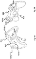
- FIG. 8 provides a side view of an embodiment of the first handheld controller 401.
- the first handheld controller 401 includes user input components (a thumbstick 404a, push buttons 404b-404e, and a trigger button (not shown)), a haptic actuator (e.g., actuator 406), and a sensor 408 configured to sense at least one of motion and orientation of the controller 401.
- the haptic actuator 406 may be the only haptic actuator of the first handheld controller 401, or may be a haptic actuator in a set of haptic actuators of the first handheld controller 401.
- the haptic actuator 406 may be denoted as the first haptic actuator of the assembly 400, and a haptic actuator in the assembly base 111 may be denoted as the second haptic actuator of the assembly 400.
- the first handheld controller 401 has a groove 407a at one end 409a of the first handheld controller 401 and another groove 407b at the other end 409b of the controller 401.
- the grooves 407a, 407b may be used to attach the first handheld controller 401 to the assembly base 111 and to the second handheld controller 411, respectively.
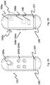
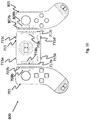
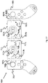
- FIGS. 9A and 9B provide perspective views of an embodiment of the second handheld controller 411.
- the second handheld controller 411 includes multiple user input components (thumbsticks 414a, 414b, push buttons (e.g., directional buttons) 414c-414f, 414g-414j, toggle buttons 414o, 414p, and trigger buttons 414m, 414n), and a haptic actuator 416, and an attachment component 412.
- the attachment component 412 may be attachable to and detachable from an end 409b of the first handheld controller 401.
- the haptic actuator 416 may be the only haptic actuator of the second handheld controller 411, or may be an actuator in a set of haptic actuators of the second handheld controller 411. In some instances, the haptic actuator 416 may be denoted the third haptic actuator of the assembly 400.
- one or more user input components in the first handheld controller 401 may be disabled in functionality.
- the functionality of the disabled user input components may be replaced by one or more user input components in the second handheld controller 411.
- the thumbstick 404a in the first handheld controller 401 may be disabled.
- Thumbstick 414a or 414b in the second handheld controller 411 may be activated and replace the use of thumbstick 404a.
- a control unit e.g., control unit 120 that controls one or more haptic effects in the assembly 400 may be located in at least one of the first handheld controller 401, the second handheld controller 411, and the assembly base 111.
- the control unit may be configured to vary the haptic effect for the peripheral device assembly 400 based on whether the second handheld controller 411 is attached to or detached from the first handheld controller 401.
- the control unit when the first handheld controller 401 is attached to the assembly base 111 and is not attached to the second handheld controller 411, the control unit may be configured to select an actuator in the first handheld controller 401, and no actuator in the second handheld controller 411, to generate a haptic effect. In an embodiment, when the first handheld controller 401 is attached to both the assembly base 111 and the second handheld controller 411, the control unit may be configured to select an actuator 416 in the second handheld controller 411 to generate a haptic effect. In an embodiment, when the second handheld controller 411 is attached to the first handheld controller 401, the haptic actuator 416 in the second handheld controller 411 may supplement or replace the haptic actuator 406 in the first handheld controller 401 for generating one or more haptic effects.
- the second handheld controller 411 may be configured as a two-handed controller, and the first handheld controller 401 may be configured as a one-handed controller. In such cases, the second handheld controller 411 may be better suited to receiving a stronger haptic effect.
- the control unit may increase a level of haptic effect intensity when the second handheld controller 411 is attached in the assembly 400. For example, when the first handheld controller 401 is attached to the assembly base 111 and is not attached to the second handheld controller 411, such that a user would be holding the first handheld controller 401 with one hand, the control unit may be configured to select an actuator 406 with a first level of output intensity to generate a haptic effect.
- the control unit may be configured to select the actuator 406 and/or actuator 416, with a second level of intensity that is higher than the first level of output intensity, to generate a stronger haptic effect.
- FIGS. 9A and 9B further show the attachment component 412 of the second handheld controller 411.
- the attachment component 412 may, for instance, attach to the end 409b of the first handheld controller 401.
- the attachment component 412 may be similar in structure to the attachment component 112 in FIG. 4 .
- the attachment component 412 may include a sleeve having a groove and a ball extendable from the groove. The ball may be configured to extend from the groove in the attachment component 412 to another groove 407b in the first handheld controller 401 when the two grooves are aligned. When the ball is extended to the groove 407b, the two handheld controllers 401, 411 may be locked in an attached configuration.
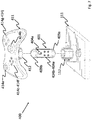
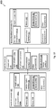
- FIG. 10 is a functional diagram of the peripheral device assembly 400.
- the functional diagram depicts communication between the first handheld controller 401 and the assembly base 111, and communication between the second handheld controller 411 and the assembly base 111.
- the assembly base may relay the communication to, e.g., a gaming console or any other computer. In some instances, however, one or both of the handheld controllers 401 and 411 may be configured to directly communicate with a gaming console.
- FIG. 10 depicts the first handheld controller 401 to include user input components 404a-404e, haptic actuator 406, sensor 408 (as shown in FIG. 8 ), a storage device 403, a communication interface 405, and a battery 430.
- FIG. 10 depicts the first handheld controller 401 to include user input components 404a-404e, haptic actuator 406, sensor 408 (as shown in FIG. 8 ), a storage device 403, a communication interface 405, and a battery 430.
- FIG. 10 depicts the first handheld controller 401 to include user input components
- the second handheld controller 411 further depicts the second handheld controller 411 to include user input components 414a-414o, attachment component 412, haptic actuator 416 (as shown in FIGS. 9A and 9B ), a communication interface 415, a storage device 413, and a battery 440.
- the functional diagram for the assembly base 111 is similar to that in FIG. 5 , and includes a control unit 120, haptic actuators 116a, 116b, an attachment component 112, a communication interface 115, and a storage device 113.
- the second handheld controller 411 does not include any sensor for sensing motion or orientation of the second handheld controller 411.
- FIG. 11 provides an embodiment in which the assembly base 511 may include at least two attachment components 512, 513 that are attachable to and detachable from two respective handheld controllers (e.g., handheld controllers 101, 401).
- Each of the attachment components 512,513 may have a structure similar to the attachment component 112 in FIG. 4 .
- each of the attachment components 512, 513 may have a groove with a ball extendable from the groove. When the ball in one of the attachment components is in an extended position, the attachment component may be locked to a respective handheld controller.
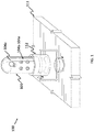
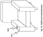
- FIG. 12 provides another embodiment of an assembly base 611 that is incorporated into a piece of furniture.
- assembly base 611 may have a body that is part of a piece of furniture, such as a chair or sofa.
- the assembly base 611 may have an attachment component 612 that is integrated into the furniture (e.g., into an arm rest of the chair).
- This embodiment may provide an assembly base 611 that is more likely to remain stationary, which may provide enhanced stability for gameplay.
- FIGS. 13-18 show modular peripheral device assemblies in which a handheld controller is magnetically attachable (e.g., via permanent magnets and/or electromagnets) to an assembly base (or to another handheld controller).
- FIG. 13 illustrates a peripheral device assembly 700 in which a handheld controller 701 is magnetically attachable to and detachable from an assembly base 711 via an attachment region 707a at a base or bottom of the controller 701 and a corresponding attachment region 717a (e.g., a receiving portion) in the assembly base 711.
- FIGS. 16 and 17 illustrate modular peripheral device assemblies 800, 900 in which a first handheld controller 701 and a second handheld controller 801 are attached at respective attachment regions 707b, 807b to the same assembly base 711 ( FIG. 16 ) and to respective assembly bases 711, 911 ( FIG. 17 ).
- the peripheral device assembly 700 is configured to permit the handheld controller 701 to be magnetically attached to the assembly base 711 at a base of the controller 701.
- the handheld controller 701 may be pivotable within the attachment region 717a of the assembly base 711, such that the peripheral device assembly 700 is operable as a joystick when the handheld controller 701 is attached to the assembly base 711.
- the handheld controller 701 includes one or more user input components, one or more attachment regions, and one or more magnets. In some embodiments, the handheld controller 701 further includes one or more sensors and one or more haptic actuators. As shown in FIGS. 13 and 14A , the plurality of user input components may include a thumbstick 704a, a trigger button 704b, and/or push buttons 704c-704f. As further shown in FIGS. 13 and 14A , the attachment regions in the handheld controller 701 may include attachment region 707a at a base of the controller 701 and an attachment region 707b at a side of the controller 701.
- a magnet 708a may be disposed at (e.g., within the boundary of, or adjacent to) the attachment region 707a, and a magnet 708b may be disposed at the attachment region 707b. Each of the magnets 708a, 708b may be used for attachment with the assembly base 711.
- a sensor in the handheld controller 701 may be configured to track at least one of motion and orientation of the handheld controller 701.
- any haptic actuator in the handheld controller 701 may include one or more of the magnets 708a, 708b.
- any haptic actuator in the controller 701 is separate from the one or more magnets 708a, 708b.
- the first handheld controller 701, the second handheld controller 801, and the assembly base 711 may further include any of the components shown in the functional diagrams of FIGS. 5 and 10 .
- the assembly base 711 may include a plurality of attachment regions 717a, 717b, 717c, and a plurality of respective magnets 718a, 718b, 718c disposed at the respective attachment regions.
- the attachment region 717a and the magnet 718a may form an attachment component to attach the assembly base 711 to a base of the handheld controller 711.
- the attachment region 717a may form a receiving portion 717a disposed at a surface of the assembly base 711, and may be shaped to receive the attachment region 707a of the handheld controller 701.
- the attachment region 707a may curve outward and have a semi-circular end, elliptical end, or other curved-end such that the attachment region 707a has a circular, or elliptical cross section, while the receiving portion 717a may form a recess having a complementary shape that fits around the semi-circular end, elliptical end, or other curved-end of the attachment region 707a so as to receive the attachment region 707a.
- the attachment region 707a of the handheld controller 701 may be attachable to the attachment region 717a of the assembly base 711 via the magnet 708a and the magnet 718a. In this attached configuration, the handheld controller 701 is pivotable about the receiving portion 717a such that the peripheral device assembly 700 is operable as a joystick when the handheld controller 701 is attached to the assembly base 711.
- FIGS. 13 , 15 and 16 further show an embodiment in which the assembly base 711 includes hooks 715a-715d that are usable in a wearables context. As described in later figures ( FIGS. 19A and 19B ), the hooks 715a-715d may be attached to straps, which may in turn be attached to a user's body.
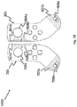
- FIG. 16 illustrates a modular peripheral device assembly 800 in which two handheld controllers (701 and 801) are attached to the assembly base 711.
- the peripheral device assembly 800 may be used, for example, as a two-handed game controller.
- the handheld controller 701 and assembly base 711 are described above with respect to FIGS. 13 , 14A, and 15 .
- the handheld controller 801 is shown in FIG. 14B .
- the handheld controller 801 includes one or more user input components (e.g., a thumbstick 804a, a trigger button, and push buttons 804c-804f), one or more attachment regions 807a, 807b, one or more magnets 808a, 808b disposed at the respective attachment regions 807a, 807b, one or more motion or orientation sensors, and one or more haptic actuators.
- the handheld controller 701 may be a left-handed controller, and the handheld controller 801 may be a right-handed controller.
- the base of the handheld controller 701, at the attachment region 708a may curve in a first direction away from the assembly base 711. Meanwhile, a base of the handheld controller 801, at the attachment region 808a, may curve in a second and opposite direction away from the assembly base 711.
- the handheld controller 701, the handheld controller 801, and the assembly base 711 may be magnetically attached as a peripheral device assembly 800.
- the attachment region 707b at a side of controller 701 may be attached to a corresponding attachment region 717b at a side of the assembly base 711.
- the attachment may be achieved via magnets 708b and 718b in the controller 701 and base 711, respectively.
- the attachment regions 707b, 717b are both substantially flat.
- the attachment regions 707b, 717b have complementary shapes (e.g., a protruding shape and a complementary recessed shape).
- an attachment region 717c at an opposite side of the assembly base 711 may be attached to an attachment region 807b at a side of the controller 801, via respective magnets 808b, 718c in the controller 801 and the assembly base 711, respectively.
- the handheld controllers 701, 801 and the assembly base 711 may be detachable from each other, such as through being pulled apart.
- one or more of the magnets in the assembly 800 may be deactivated, wherein this deactivation may need to be performed before the handheld controllers 701, 801 and the assembly base 711 can be detached from each other.
- the magnets in the assembly 800 may be electromagnets that are able to be deactivated. In such an embodiment, the electromagnet may be deactivated by ceasing power to the electromagnet.
- At least one of the first handheld controller 701, the second handheld controller 801, and the assembly base 711 may be configured to generate a haptic effect utilizing at least one of the magnets 708a, 708b, 808a, 808b, and 718a-718c.
- the magnets can generate a haptic effect by varying magnetic strength of two magnets on two respective handheld controllers, or on a respective handheld controller and a respective assembly base, to make the two objects harder or easier to pull apart. For instance, if the magnets were electromagnets, their magnetic strength may be varied by varying a current that is applied to the electromagnets.
- the magnets can create a haptic effect by varying magnetic strength by varying magnetic strength of two magnets on two respective handheld controllers, or on a respective handheld controller and respective assembly base, as the user is moving the two objects relative to each other.
- FIG. 17 shows another embodiment in which one or more handheld controllers and one or more assembly bases can be attached to form a modular peripheral device assembly 900.
- the peripheral device assembly 900 may include the handheld controllers 701, 801, and assembly base 711, as shown in FIG. 16 , and further include a second assembly base 911.
- the second assembly base 911 may be included in the peripheral device assembly 900 to increase the width of the assembly 900 (as compared to peripheral device assembly 800) for a two-handed game controller.
- the second assembly base 911 includes one or more attachment regions and one or more respective magnets at those regions.
- the attachment regions include attachment regions 917a, 917b, and 917c.
- the magnets include magnets 918a, 918b, and 918c at the respective attachment regions.
- the attachment region 917a and magnet 918a may be used for attachment with an attachment region 707a or 807a of the handheld controller 701 and 801, respectively.
- the attachment regions 917b and 917c may be at opposite sides of the second assembly base 911.
- the respective magnets 918b and 918c may also be at opposite sides of the second assembly base 911.
- the attachment region 707b at a side of the handheld controller 701 is attachable to an attachment region 717b at a first side of the first assembly base 711, in a similar manner as shown and described with reference to FIG. 16 .
- an attachment region 717c at a second, opposite side of the first assembly base 711 may be attachable to an attachment region 917b at a first side of the second assembly base 911.
- an attachment region 917c at a second, opposite side of the second assembly base 911 may be attachable to an attachment region 807b at a side of the second handheld controller 801.
- the attachment in FIG. 17 may be performed using magnets 708b, 718b, 718c, 918b, 918c, and 808b.
- a peripheral device assembly may include more (e.g., three) or fewer assembly bases.
- FIG. 18 shows a peripheral device assembly 1000 that has no assembly base.
- the peripheral device assembly 1000 includes only the handheld controller 701 and the handheld controller 801, which may be magnetically attached at an attachment region 707b and 807b of the respective handheld controllers. The magnetic attachment may be accomplished using magnets 708b and 808b of the respective handheld controllers.
- peripheral device assemblies 700-1000 may include a control unit for controlling one or more haptic effects, such as control unit 120.
- the control unit may control the haptic effects, including what type of haptic effect to generate, an output intensity of the haptic effect, and/or which haptic actuators to use to generate the haptic effect.
- the control unit may control the haptic effects based on the techniques discussed above with respect to FIGS. 1-12 . For example, it may control the haptic effects based on whether the handheld controller 701, 801 is/are attached to the assembly base 711, or whether the handheld controller 701, 801 is/are detached from the assembly base 711, and/or based on an application event associated with the haptic effect.
- the assembly base 711 may include one or more hooks 715a-715d that can be used for a wearables application.
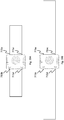
- FIGS. 19A and 19B illustrate straps being attached to the hooks 715a-715d for wearables applications.
- FIG. 19A shows the assembly base 711 being hooked to a wrist strap, which may be attached to a user's wrist.
- FIG. 19B shows the assembly base 711 being hooked to a longer strap which may be attached around a user's thigh, for instance.
- Both wearables straps may provide, e.g., greater portability of the peripheral device assembly, by making it easier for a user to move with or to transport the peripheral device assembly.
- an assembly base may be included as part of a glove.
- the attachment component for this assembly base may be attached to a surface of a palm portion of the glove, or attached to a surface on the other side of the glove.
- This configuration may allow a user to wear the glove on one hand (e.g., left hand), and attach a handheld controller with an attachment component on the glove. The user may then use the other hand (e.g., right hand) to control the handheld controller, e.g., as a joystick.
- the magnets discussed herein may be used to approximate the distance between two components (e.g., between a handheld controller and an assembly base) before the two components are attached to each other.
- the magnets may be part of a hall effect sensor used to detect proximity between the two components.
- software may be used to customize inputs/haptic preferences.
- one or more of the handheld controllers and/or assembly bases described herein may include a touch screen or other display element.
- Embodiments hereof may be adapted for use in various hardware and system interface to include a set of connection or interface points into a haptic environment, e.g., input/output, function calls, libraries such as DLLs, etc.
- Various control units described herein may include a microprocessor, FPGA, PGA, or any combination thereof.
- the microprocessor may execute one or more computer-readable instructions stored on a non-transitory computer-readable medium.
- Embodiments may be referred to as modular haptic peripheral device assembly and/or a buildable haptic controller.
Landscapes
- Engineering & Computer Science (AREA)
- Multimedia (AREA)
- General Engineering & Computer Science (AREA)
- Theoretical Computer Science (AREA)
- Human Computer Interaction (AREA)
- Physics & Mathematics (AREA)
- General Physics & Mathematics (AREA)
- Automation & Control Theory (AREA)
- Software Systems (AREA)
- Computer Hardware Design (AREA)
- Computer Graphics (AREA)
- User Interface Of Digital Computer (AREA)
- Toys (AREA)
- Programmable Controllers (AREA)
- Casings For Electric Apparatus (AREA)
Priority Applications (1)
| Application Number | Priority Date | Filing Date | Title |
|---|---|---|---|
| EP18195682.2A EP3454183A1 (fr) | 2016-02-18 | 2017-02-16 | Ensemble de dispositif périphérique modulaire |
Applications Claiming Priority (2)
| Application Number | Priority Date | Filing Date | Title |
|---|---|---|---|
| US201662297087P | 2016-02-18 | 2016-02-18 | |
| US15/350,715 US10198074B2 (en) | 2016-02-18 | 2016-11-14 | Haptically-enabled modular peripheral device assembly |
Related Child Applications (1)
| Application Number | Title | Priority Date | Filing Date |
|---|---|---|---|
| EP18195682.2A Division EP3454183A1 (fr) | 2016-02-18 | 2017-02-16 | Ensemble de dispositif périphérique modulaire |
Publications (2)
| Publication Number | Publication Date |
|---|---|
| EP3208693A2 true EP3208693A2 (fr) | 2017-08-23 |
| EP3208693A3 EP3208693A3 (fr) | 2017-08-30 |
Family
ID=58054061
Family Applications (3)
| Application Number | Title | Priority Date | Filing Date |
|---|---|---|---|
| EP17156497.4A Withdrawn EP3208693A3 (fr) | 2016-02-18 | 2017-02-16 | Ensemble de dispositif périphérique modulaire |
| EP18195682.2A Withdrawn EP3454183A1 (fr) | 2016-02-18 | 2017-02-16 | Ensemble de dispositif périphérique modulaire |
| EP17156488.3A Active EP3208692B1 (fr) | 2016-02-18 | 2017-02-16 | Ensemble de dispositif périphérique modulaire à effet haptique |
Family Applications After (2)
| Application Number | Title | Priority Date | Filing Date |
|---|---|---|---|
| EP18195682.2A Withdrawn EP3454183A1 (fr) | 2016-02-18 | 2017-02-16 | Ensemble de dispositif périphérique modulaire |
| EP17156488.3A Active EP3208692B1 (fr) | 2016-02-18 | 2017-02-16 | Ensemble de dispositif périphérique modulaire à effet haptique |
Country Status (5)
| Country | Link |
|---|---|
| US (2) | US10198074B2 (fr) |
| EP (3) | EP3208693A3 (fr) |
| JP (1) | JP6974010B2 (fr) |
| KR (1) | KR20170097564A (fr) |
| CN (1) | CN107092344B (fr) |
Cited By (4)
| Publication number | Priority date | Publication date | Assignee | Title |
|---|---|---|---|---|
| EP3470960A1 (fr) * | 2017-10-11 | 2019-04-17 | Immersion Corporation | Effets haptiques associés à de multiples dispositifs périphériques |
| FR3096162A1 (fr) * | 2019-05-15 | 2020-11-20 | Robert Bosch Gmbh | « Télécommande à manette d’engin de travaux » |
| EP3785773A1 (fr) * | 2019-08-30 | 2021-03-03 | Nintendo Co., Ltd. | Appareil périphérique, commande de jeu, système de traitement d'informations et procédé de traitement d'informations |
| WO2022157416A1 (fr) * | 2021-01-25 | 2022-07-28 | Ps Audio Design Oy | Procédé et agencement pour produire des effets haptiques dans un dispositif utilisateur |
Families Citing this family (29)
| Publication number | Priority date | Publication date | Assignee | Title |
|---|---|---|---|---|
| JP6074534B2 (ja) | 2015-06-12 | 2017-02-01 | 任天堂株式会社 | ゲームコントローラ |
| US9751008B2 (en) | 2015-06-12 | 2017-09-05 | Nintendo Co., Ltd. | Game controller |
| EP3305382B1 (fr) | 2016-10-06 | 2019-02-27 | Nintendo Co., Ltd. | Accessoire |
| US10963054B2 (en) | 2016-12-15 | 2021-03-30 | Sony Interactive Entertainment Inc. | Information processing system, vibration control method and program |
| JP6799077B2 (ja) | 2016-12-15 | 2020-12-09 | 株式会社ソニー・インタラクティブエンタテインメント | 情報処理システム、コントローラデバイス、コントローラデバイスの制御方法、及びプログラム |
| US10963055B2 (en) * | 2016-12-15 | 2021-03-30 | Sony Interactive Entertainment Inc. | Vibration device and control system for presenting corrected vibration data |
| WO2018193514A1 (fr) | 2017-04-18 | 2018-10-25 | 株式会社ソニー・インタラクティブエンタテインメント | Dispositif de commande de vibration |
| WO2018193513A1 (fr) | 2017-04-18 | 2018-10-25 | 株式会社ソニー・インタラクティブエンタテインメント | Dispositif de commande de vibration |
| JP6887011B2 (ja) | 2017-04-19 | 2021-06-16 | 株式会社ソニー・インタラクティブエンタテインメント | 振動制御装置 |
| WO2018198229A1 (fr) | 2017-04-26 | 2018-11-01 | 株式会社ソニー・インタラクティブエンタテインメント | Dispositif de commande de vibration |
| WO2019038887A1 (fr) | 2017-08-24 | 2019-02-28 | 株式会社ソニー・インタラクティブエンタテインメント | Dispositif de commande de vibration |
| JP6893561B2 (ja) | 2017-08-24 | 2021-06-23 | 株式会社ソニー・インタラクティブエンタテインメント | 振動制御装置 |
| WO2019043781A1 (fr) | 2017-08-29 | 2019-03-07 | 株式会社ソニー・インタラクティブエンタテインメント | Dispositif de commande de vibration, procédé de commande de vibration et programme |
| JP7042061B2 (ja) * | 2017-11-10 | 2022-03-25 | 株式会社バンダイナムコエンターテインメント | 操作入力システム、操作入力装置及びゲームシステム |
| CN109085922B (zh) | 2018-07-27 | 2021-02-12 | 北京航空航天大学 | 一种多元触觉融合反馈手柄 |
| CN109045683A (zh) * | 2018-07-29 | 2018-12-21 | 赣州研顺飞科技有限公司 | 一种Ar成像技术用游戏手柄 |
| US10761607B2 (en) * | 2018-08-21 | 2020-09-01 | Disney Enterprises Inc. | Multi-mode haptic effects delivery system |
| FR3086185B1 (fr) * | 2018-09-20 | 2023-06-16 | Protubevr | Dispositif de retour de force mecanique concu pour simuler un impact physique lors d'un evenement de jeu video. |
| US10744406B2 (en) * | 2018-10-19 | 2020-08-18 | North Carolina State University | Temporal axial alignment adapter for VR hand controllers |
| US11020656B2 (en) * | 2019-07-16 | 2021-06-01 | Joshua Roehrig | Handheld tactile simulator system for enhancing the motion picture viewing experience |
| KR102242200B1 (ko) * | 2019-09-25 | 2021-04-20 | 한국과학기술정보연구원 | 햅틱입력장치 및 그 동작 방법 |
| US10868436B1 (en) * | 2019-10-02 | 2020-12-15 | Kingston Technology Corporation | Mobile device gaming accessory with swappable battery packs and wireless charging |
| US11439902B2 (en) * | 2020-05-01 | 2022-09-13 | Dell Products L.P. | Information handling system gaming controls |
| US11260297B2 (en) * | 2020-05-01 | 2022-03-01 | Dell Products L.P. | Information handling system wheel input device |
| CN112256136B (zh) * | 2020-11-13 | 2022-07-15 | 腾讯科技(深圳)有限公司 | 一种触觉反馈装置、方法、电子设备及人机交互系统 |
| WO2023015490A1 (fr) * | 2021-08-11 | 2023-02-16 | 深圳市韶音科技有限公司 | Système et procédé de commande de terminal |
| US11847267B2 (en) * | 2022-05-11 | 2023-12-19 | Hewlett-Packard Development Company, L.P. | Input device tracking systems |
| US20240075381A1 (en) * | 2022-09-06 | 2024-03-07 | ACCO Brands Corporation | Mobile game controller and full feature game controller combination device |
| KR20240094676A (ko) * | 2022-12-16 | 2024-06-25 | 이성호 | Vr 연동 항공게임용 조이스틱 |
Family Cites Families (26)
| Publication number | Priority date | Publication date | Assignee | Title |
|---|---|---|---|---|
| US6004134A (en) * | 1994-05-19 | 1999-12-21 | Exos, Inc. | Interactive simulation including force feedback |
| US6422941B1 (en) * | 1994-09-21 | 2002-07-23 | Craig Thorner | Universal tactile feedback system for computer video games and simulations |
| US5691898A (en) * | 1995-09-27 | 1997-11-25 | Immersion Human Interface Corp. | Safe and low cost computer peripherals with force feedback for consumer applications |
| TW387816B (en) * | 1996-03-05 | 2000-04-21 | Sega Enterprises Kk | Controller and expansion unit for controller |
| JP2000218041A (ja) * | 1999-01-29 | 2000-08-08 | Alps Electric Co Ltd | ゲーム機器用のコントローラ |
| JP2004362555A (ja) * | 2004-05-12 | 2004-12-24 | Sony Corp | 再生表示装置および再生表示方法 |
| US20060109251A1 (en) | 2004-11-19 | 2006-05-25 | Jesse Kelly | Combined keyboard and movement detection system |
| US7927216B2 (en) | 2005-09-15 | 2011-04-19 | Nintendo Co., Ltd. | Video game system with wireless modular handheld controller |
| US20070273643A1 (en) | 2006-05-24 | 2007-11-29 | Sandisk Il Ltd. | Dongle joystick |
| EP2338154A1 (fr) | 2008-09-20 | 2011-06-29 | Ringbow Ltd. | Dispositif porté au doigt et procédés d interaction et procédés de communications |
| US8939838B2 (en) | 2008-09-30 | 2015-01-27 | Apple Inc. | Accessory for playing games with a portable electronic device |
| WO2010071827A2 (fr) | 2008-12-19 | 2010-06-24 | Immersion Corporation | Jeu de peinture interactif et dispositif de commande associé |
| US8497767B2 (en) | 2009-03-02 | 2013-07-30 | Butterfly Haptics, LLC | Magnetic levitation haptic interface system |
| US8241126B2 (en) | 2009-11-04 | 2012-08-14 | Valve Corporation | Video game controller having user swappable control components |
| FR2954980B1 (fr) * | 2010-01-04 | 2012-02-10 | Guillemot Corp | Joystick a ressorts de compensation, procede de fabrication et manette correspondants. |
| US8599162B2 (en) * | 2010-03-18 | 2013-12-03 | Chris Argiro | Actionable-object controller and data-entry attachment for touchscreen-based electronics |
| JP5550433B2 (ja) * | 2010-04-22 | 2014-07-16 | 任天堂株式会社 | 操作装置および情報処理システム |
| US8821284B2 (en) | 2010-05-10 | 2014-09-02 | Performance Designed Products Llc | Adapter apparatus for a handheld controller |
| JP5175908B2 (ja) | 2010-09-14 | 2013-04-03 | 株式会社東芝 | 情報処理装置及びプログラム |
| US9164595B2 (en) | 2013-03-08 | 2015-10-20 | Darren C. PETERSEN | Mechanical actuator apparatus for a touchscreen |
| EP3211511A1 (fr) * | 2013-03-15 | 2017-08-30 | Immersion Corporation | Périphérique haptique programmable |
| KR20140117184A (ko) | 2013-03-26 | 2014-10-07 | 삼성전자주식회사 | 디스플레이 장치 및 이를 제어하는 원격 제어 장치 |
| KR101815720B1 (ko) | 2013-05-21 | 2018-01-05 | 삼성전자주식회사 | 진동 제어 방법 및 장치 |
| US9649558B2 (en) * | 2014-03-14 | 2017-05-16 | Sony Interactive Entertainment Inc. | Gaming device with rotatably placed cameras |
| US10045195B2 (en) * | 2015-05-29 | 2018-08-07 | Nike, Inc. | Athletic data aggregation and display system |
| US10748406B2 (en) * | 2015-07-02 | 2020-08-18 | Aktiebolaget Skf | Machine condition measurement system with haptic feedback |
-
2016
- 2016-11-14 US US15/350,715 patent/US10198074B2/en active Active
-
2017
- 2017-02-14 KR KR1020170019886A patent/KR20170097564A/ko unknown
- 2017-02-15 JP JP2017025532A patent/JP6974010B2/ja active Active
- 2017-02-16 EP EP17156497.4A patent/EP3208693A3/fr not_active Withdrawn
- 2017-02-16 EP EP18195682.2A patent/EP3454183A1/fr not_active Withdrawn
- 2017-02-16 EP EP17156488.3A patent/EP3208692B1/fr active Active
- 2017-02-17 CN CN201710085748.XA patent/CN107092344B/zh not_active Expired - Fee Related
-
2019
- 2019-01-30 US US16/262,269 patent/US20190163279A1/en not_active Abandoned
Non-Patent Citations (1)
| Title |
|---|
| None |
Cited By (5)
| Publication number | Priority date | Publication date | Assignee | Title |
|---|---|---|---|---|
| EP3470960A1 (fr) * | 2017-10-11 | 2019-04-17 | Immersion Corporation | Effets haptiques associés à de multiples dispositifs périphériques |
| FR3096162A1 (fr) * | 2019-05-15 | 2020-11-20 | Robert Bosch Gmbh | « Télécommande à manette d’engin de travaux » |
| EP3785773A1 (fr) * | 2019-08-30 | 2021-03-03 | Nintendo Co., Ltd. | Appareil périphérique, commande de jeu, système de traitement d'informations et procédé de traitement d'informations |
| US11148043B2 (en) | 2019-08-30 | 2021-10-19 | Nintendo Co., Ltd. | Peripheral apparatus, game controller, information processing system, and information processing method |
| WO2022157416A1 (fr) * | 2021-01-25 | 2022-07-28 | Ps Audio Design Oy | Procédé et agencement pour produire des effets haptiques dans un dispositif utilisateur |
Also Published As
| Publication number | Publication date |
|---|---|
| US20190163279A1 (en) | 2019-05-30 |
| CN107092344A (zh) | 2017-08-25 |
| EP3208693A3 (fr) | 2017-08-30 |
| EP3208692A1 (fr) | 2017-08-23 |
| JP2017146971A (ja) | 2017-08-24 |
| JP6974010B2 (ja) | 2021-12-01 |
| EP3208692B1 (fr) | 2020-12-23 |
| EP3454183A1 (fr) | 2019-03-13 |
| KR20170097564A (ko) | 2017-08-28 |
| US20170242486A1 (en) | 2017-08-24 |
| CN107092344B (zh) | 2021-05-04 |
| US10198074B2 (en) | 2019-02-05 |
Similar Documents
| Publication | Publication Date | Title |
|---|---|---|
| EP3208692B1 (fr) | Ensemble de dispositif périphérique modulaire à effet haptique | |
| US10343061B2 (en) | Haptic actuators having magnetic elements and at least one electromagnet | |
| US11086416B2 (en) | Input device for use in an augmented/virtual reality environment | |
| US10279251B2 (en) | Programmable haptic peripheral | |
| CN107533369B (zh) | 带有外围装置的手套指尖的磁性跟踪 | |
| US9833700B2 (en) | Connectable hand-held controllers for virtual-reality systems | |
| US9778743B2 (en) | Gaming device having a haptic-enabled trigger | |
| US10359853B2 (en) | Haptic peripheral having a plurality of deformable membranes and a motor to move radial pins | |
| US10712812B2 (en) | Foot operated navigation and interaction for virtual reality experiences | |
| US20190176033A1 (en) | Input apparatus for a computer | |
| US20060111180A1 (en) | Touch-control game controller | |
| US20140368428A1 (en) | System and Method For Enhanced Gesture-Based Interaction | |
| WO2012104772A1 (fr) | Système pouvant être commandé par des gestes et utilisant la proprioception pour créer un cadre de référence absolu | |
| KR20170131237A (ko) | 햅틱 효과들을 제공하기 위한 기계식 키 및 통합된 스마트 재료 액추에이터를 포함하는 햅틱적으로 향상된 사용자 입력 요소를 갖는 햅틱 주변 장치 | |
| US8701026B2 (en) | User interface | |
| US20090079745A1 (en) | System and method for intuitive interactive navigational control in virtual environments | |
| Chastine et al. | A study of gesture-based first person control | |
| Shibata et al. | Improvement of a Joystick Controller for Electric Wheelchair User | |
| Schlattmann et al. | Real-time bare-hands-tracking for 3D games | |
| Baudisch et al. | Soap: How to make a mouse work in mid-air | |
| Zaiţi et al. | Glove-based input for reusing everyday objects as interfaces in smart environments | |
| Powers et al. | A novel video game peripheral for detecting fine hand motion and providing haptic feedback |
Legal Events
| Date | Code | Title | Description |
|---|---|---|---|
| PUAI | Public reference made under article 153(3) epc to a published international application that has entered the european phase |
Free format text: ORIGINAL CODE: 0009012 |
|
| PUAL | Search report despatched |
Free format text: ORIGINAL CODE: 0009013 |
|
| AK | Designated contracting states |
Kind code of ref document: A2 Designated state(s): AL AT BE BG CH CY CZ DE DK EE ES FI FR GB GR HR HU IE IS IT LI LT LU LV MC MK MT NL NO PL PT RO RS SE SI SK SM TR |
|
| AX | Request for extension of the european patent |
Extension state: BA ME |
|
| AK | Designated contracting states |
Kind code of ref document: A3 Designated state(s): AL AT BE BG CH CY CZ DE DK EE ES FI FR GB GR HR HU IE IS IT LI LT LU LV MC MK MT NL NO PL PT RO RS SE SI SK SM TR |
|
| AX | Request for extension of the european patent |
Extension state: BA ME |
|
| RIC1 | Information provided on ipc code assigned before grant |
Ipc: G06F 3/0346 20130101ALI20170721BHEP Ipc: G05G 9/047 20060101ALI20170721BHEP Ipc: G06F 3/01 20060101AFI20170721BHEP Ipc: G06F 3/0338 20130101ALI20170721BHEP |
|
| 17P | Request for examination filed |
Effective date: 20180228 |
|
| RBV | Designated contracting states (corrected) |
Designated state(s): AL AT BE BG CH CY CZ DE DK EE ES FI FR GB GR HR HU IE IS IT LI LT LU LV MC MK MT NL NO PL PT RO RS SE SI SK SM TR |
|
| GRAP | Despatch of communication of intention to grant a patent |
Free format text: ORIGINAL CODE: EPIDOSNIGR1 |
|
| INTG | Intention to grant announced |
Effective date: 20180507 |
|
| GRAJ | Information related to disapproval of communication of intention to grant by the applicant or resumption of examination proceedings by the epo deleted |
Free format text: ORIGINAL CODE: EPIDOSDIGR1 |
|
| INTC | Intention to grant announced (deleted) | ||
| 17Q | First examination report despatched |
Effective date: 20180928 |
|
| STAA | Information on the status of an ep patent application or granted ep patent |
Free format text: STATUS: THE APPLICATION IS DEEMED TO BE WITHDRAWN |
|
| 18D | Application deemed to be withdrawn |
Effective date: 20200901 |