EP3208531A2 - Kraftfahrzeug-scheinwerfer mit einem flüssigkristalldisplay - Google Patents
Kraftfahrzeug-scheinwerfer mit einem flüssigkristalldisplay Download PDFInfo
- Publication number
- EP3208531A2 EP3208531A2 EP17156657.3A EP17156657A EP3208531A2 EP 3208531 A2 EP3208531 A2 EP 3208531A2 EP 17156657 A EP17156657 A EP 17156657A EP 3208531 A2 EP3208531 A2 EP 3208531A2
- Authority
- EP
- European Patent Office
- Prior art keywords
- liquid crystal
- matrix element
- crystal matrix
- light
- beam splitter
- Prior art date
- Legal status (The legal status is an assumption and is not a legal conclusion. Google has not performed a legal analysis and makes no representation as to the accuracy of the status listed.)
- Granted
Links
- 239000004973 liquid crystal related substance Substances 0.000 title claims abstract description 124
- 239000011159 matrix material Substances 0.000 claims abstract description 115
- 230000010287 polarization Effects 0.000 claims abstract description 35
- 230000003287 optical effect Effects 0.000 claims description 23
- 239000010409 thin film Substances 0.000 claims description 3
- 238000005286 illumination Methods 0.000 description 17
- 238000009826 distribution Methods 0.000 description 14
- 230000005540 biological transmission Effects 0.000 description 1
- 230000015572 biosynthetic process Effects 0.000 description 1
- 230000001419 dependent effect Effects 0.000 description 1
- 230000000694 effects Effects 0.000 description 1
- 238000005516 engineering process Methods 0.000 description 1
- 230000007613 environmental effect Effects 0.000 description 1
- 238000003384 imaging method Methods 0.000 description 1
- 238000002955 isolation Methods 0.000 description 1
- 230000028161 membrane depolarization Effects 0.000 description 1
- 238000012634 optical imaging Methods 0.000 description 1
- 230000005855 radiation Effects 0.000 description 1
- 229910052710 silicon Inorganic materials 0.000 description 1
- 239000010703 silicon Substances 0.000 description 1
- 229910000679 solder Inorganic materials 0.000 description 1
Images

Classifications
-
- F—MECHANICAL ENGINEERING; LIGHTING; HEATING; WEAPONS; BLASTING
- F21—LIGHTING
- F21S—NON-PORTABLE LIGHTING DEVICES; SYSTEMS THEREOF; VEHICLE LIGHTING DEVICES SPECIALLY ADAPTED FOR VEHICLE EXTERIORS
- F21S41/00—Illuminating devices specially adapted for vehicle exteriors, e.g. headlamps
- F21S41/60—Illuminating devices specially adapted for vehicle exteriors, e.g. headlamps characterised by a variable light distribution
- F21S41/63—Illuminating devices specially adapted for vehicle exteriors, e.g. headlamps characterised by a variable light distribution by acting on refractors, filters or transparent cover plates
- F21S41/64—Illuminating devices specially adapted for vehicle exteriors, e.g. headlamps characterised by a variable light distribution by acting on refractors, filters or transparent cover plates by changing their light transmissivity, e.g. by liquid crystal or electrochromic devices
- F21S41/645—Illuminating devices specially adapted for vehicle exteriors, e.g. headlamps characterised by a variable light distribution by acting on refractors, filters or transparent cover plates by changing their light transmissivity, e.g. by liquid crystal or electrochromic devices by electro-optic means, e.g. liquid crystal or electrochromic devices
-
- F—MECHANICAL ENGINEERING; LIGHTING; HEATING; WEAPONS; BLASTING
- F21—LIGHTING
- F21S—NON-PORTABLE LIGHTING DEVICES; SYSTEMS THEREOF; VEHICLE LIGHTING DEVICES SPECIALLY ADAPTED FOR VEHICLE EXTERIORS
- F21S41/00—Illuminating devices specially adapted for vehicle exteriors, e.g. headlamps
- F21S41/20—Illuminating devices specially adapted for vehicle exteriors, e.g. headlamps characterised by refractors, transparent cover plates, light guides or filters
- F21S41/285—Refractors, transparent cover plates, light guides or filters not provided in groups F21S41/24 - F21S41/2805
-
- F—MECHANICAL ENGINEERING; LIGHTING; HEATING; WEAPONS; BLASTING
- F21—LIGHTING
- F21S—NON-PORTABLE LIGHTING DEVICES; SYSTEMS THEREOF; VEHICLE LIGHTING DEVICES SPECIALLY ADAPTED FOR VEHICLE EXTERIORS
- F21S41/00—Illuminating devices specially adapted for vehicle exteriors, e.g. headlamps
- F21S41/10—Illuminating devices specially adapted for vehicle exteriors, e.g. headlamps characterised by the light source
- F21S41/12—Illuminating devices specially adapted for vehicle exteriors, e.g. headlamps characterised by the light source characterised by the type of emitted light
- F21S41/135—Polarised
Definitions
- the present invention relates to a motor vehicle headlight according to the preamble of claim 1.
- Such a headlight is from the DE 10 2013 113 807 A1 known.
- Liquid crystal matrix components are used as a display (LCD) but also in video projectors.
- Another disadvantage is a rather weak contrast ratio between luminous and non-luminous matrix elements.
- Another disadvantage is that the function of the liquid-crystal matrix elements as light-controllable segments of a light-emitting surface of the liquid-crystal matrix component illumination with linear polarized light presupposes.
- Light of conventional light sources is initially not polarized and has two portions of mutually orthogonal polarization directions.
- the light is polarized before it strikes the liquid crystal matrix device.
- the polarization is usually carried out by a polarizing filter that lets only one of the two components through and absorbs the other component.
- This document shows a motor vehicle headlamp with a light source, a polarizing beam splitter, which is arranged in a light beam emanating from the light source and divides the incident light from the light source into a first sub-beam and a second sub-beam, wherein the light of the first sub-beam a first Polarization direction and having a first Schopropagations psychologist, and wherein the light of the second sub-beam having a second polarization direction and a second Mannpropagationsraum, and having a first reflective liquid crystal matrix element region whose influence on the polarization direction of the reflected light is controllable, and with a second reflective liquid crystal matrix element region whose influence is controllable to the polarization direction of the reflected light.
- the liquid crystal matrix element regions are operated in transmission.
- the from the DE 10 2013 113 807A1 known headlight requires its own projection optics for each direction of polarization. Each of the two projection optics transmits polarized light. Headlights should generally produce light distributions that consist of unpolarized light. This may require an additional depolarization device. Since two projection optics are required, there is a doubling of the light exit surface and thus a halving of the luminance compared to a solution that requires only a projection optics.
- the known headlight is a so-called matrix headlight, in which the brightness of individual pixels of the liquid crystal element is controllable.
- matrix headlights in automotive technology, a dynamic adjustment of the light distribution of the headlamps to changing environmental conditions. For example, at night driving with high beam individual subregions of the light distribution can be darkened, so that an oncoming vehicle is not dazzled despite the high beam.
- headlights can also be equipped, for example, with micromirrors (eg DE 10 2013 113807 A1 . EP 2 813 395 A1 ) will be realized. Disadvantages of these concepts are the high costs for the micromirrors.
- the object of the present invention is to provide a headlamp of the type mentioned above, which requires a smaller light exit surface and has a greater luminance and which is also able to produce a substantially unpolarized light existing light distribution without additional depolarizers.
- the present invention differs in that the first liquid crystal matrix element region in the first sub-beam is arranged to reflect incident light back to the beam splitter from the beam splitter, and the second liquid crystal matrix element region in the second sub-beam is arranged to receive light from the beam splitter reflected back to the beam splitter.
- the liquid crystal matrix element regions are operated in reflection in the invention. Suitable liquid crystal components are known, for example, from the publication " Optical Imaging and Metrology, edited by W.Osten and N.Reingand, 2012 Wiley-VCH Publishing known.
- the light reflected back from the liquid-crystal matrix element regions is combined by the beam splitter and projected into the emission direction by means of projection optics.
- the liquid crystal matrix element regions have, above all, the task of modulating the incident light pixel by pixel in accordance with the required light function.
- a preferred embodiment is characterized in that the two liquid-crystal matrix element regions are aligned parallel to one another, and that a deflecting mirror is arranged between the second liquid-crystal matrix element region and the beam splitter.
- the two liquid crystal matrix element regions are arranged in the same plane.
- a further preferred embodiment is characterized in that the two liquid crystal matrix element areas adjoin one another and belong to the same component.
- the individual pixels of the liquid crystal matrix element regions are driven so that the polarization of the light reflected thereon is not rotated in an outer region and is rotated in an inner region, and that inner region having a larger magnification factor into one Lighting zone of the headlamp is shown, is smaller than the inner area, which is imaged with a larger magnification factor in a lighting zone of the headlamp.
- the first liquid-crystal matrix element region belongs to a first component
- that the second liquid-crystal matrix element region belongs to a second component that is separate from the first component
- a further preferred refinement is characterized in that the two liquid-crystal matrix element regions are arranged offset from one another parallel to one another in different, mutually parallel planes.
- the two liquid-crystal matrix element regions prefferably be offset parallel to one another in different planes parallel to one another, and for a distance perpendicular to the pixel surfaces between the two liquid crystal element regions to be equal to a mean distance of the deflection mirror from the beam splitter.
- the two liquid crystal matrix element regions make a right angle with each other, one surface of the Liquid crystal matrix element region facing a first side of the beam splitter and wherein a surface of the second liquid crystal matrix element region faces a second surface of the beam splitter.
- liquid-crystal matrix element regions are arranged such that the light incident from the beam splitter is incident perpendicularly on the liquid-crystal matrix element regions and thus also is reflected perpendicularly.
- a preferred embodiment is characterized by a projection optical system which is arranged behind the beam splitter in the beam path of the light reflected by the liquid crystal matrix element regions.
- a beam splitter-side focal point of the projection optics is located in the vicinity of the surfaces of the liquid-crystal matrix element regions.
- a further preferred refinement is characterized in that a first optical element is arranged between the light source and the beam splitter, and that the first optical element is set up to parallelize light emanating from the light source.
- the first optical element is a lens, a reflector or a catadioptric attachment optics.
- the polarizing beam splitter consists of two prismatic halves.
- the beam splitter is a thin film polarizer.
- FIG. 1 a headlight 10 of a motor vehicle.
- the headlight 10 has a housing 12, the light exit opening of a transparent Cover 14 is covered. Inside the housing 12 is a light module 16 and a control unit 18th
- the control unit 18 is set up, in particular programmed, to control the function of the light module 16 in response to signals from a desired driver 20 or a higher-level light control device 22 of the motor vehicle.
- the driver's desire encoder 20 is, for example, a light switch of the motor vehicle.
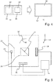
- the FIG. 2 shows details of a features of the invention having light module 16 of a headlight according to the invention.
- the light module 16 comprises a light source 24, a polarizing beam splitter 26, a first reflective liquid crystal matrix element region 28, a second reflective liquid crystal matrix element region 30, and a projection optical system 32.
- the light source 24 preferably has at least one, but preferably a plurality of light-emitting diodes.
- the light emitting diodes emit light of white color, as is permissible for motor vehicle headlights.
- a light bundle 25 of unpolarized light emanating from the light source 24 is preferably first parallelized by a first optical element 27.
- the first optical element 27 is preferably realized as a lens or as a reflector or as a catadioptric optical attachment.
- the parallelized light beam 29 emanating from the first optical element 27 is incident on the polarizing beam splitter 26.
- the first optical element 27 is located between the light source 24 and the beam splitter 26.
- the beam splitter 26 is shown here schematically as a beam splitter cube, which consists of two prismatic halves, each having the shape of a right-angled and equilateral triangle in the plane of the drawing and which are along their respective right angle opposite base surfaces assembled into a cube. The base surfaces of such a cube are then the beam-splitting surfaces 31. Contrary to this embodiment, the beam splitter 26 is preferably a thin-film polarizer.
- the beam splitting surfaces 31 of the beam splitter 26 appear as a line lying in a pz plane of a right-right coordinate system 34.
- the coordinate system 34 has an s-axis, a p-axis and a z-axis, wherein the axes are orthogonal to each other.
- the shape and position of the beam-splitting surface 31 results in this representation by shifting the beam-splitting surface 31 performing line in the S-direction.
- a light incidence plane in which light ultimately emanating from the light source 24 is incident on the beam splitter 26 is identical to the plane of the drawing and is therefore parallel to a p-z plane.
- Such a light incidence plane is defined by the direction of the incident beam and the perpendicular of the plane surface on which the beam is incident.
- the incident, unpolarized light 29 has a first portion which is polarized parallel to the pz-light incidence plane. This share is also referred to below as the p share. Its polarization direction lies in the plane of the drawing.
- the incident, unpolarized light 29 also has a second portion polarized perpendicular to the p-z light incidence plane. This share is also referred to below as the s share. Its polarization direction is perpendicular to the plane of the drawing.
- the polarizing beam splitter 26 has the property of being transparent to one of the two components and of reflecting the other component. Without limiting the generality, it should be assumed in the following that the polarizing beam splitter 26 is transparent to the p component and reflects the s component. This means that the p component passes through the beam-dividing surfaces 31 and that the s component is reflected at the beam-dividing surfaces 31. In an alternative embodiment, the polarizing beam splitter 26 is transparent to the s-component and reflects the s-component.
- the polarizing beam splitter 26 divides the light 24 directly or, if a first optical element 27 is present, light 28 incident on the first optical element 27 into a first sub-beam 36 and a second sub-beam 38.
- the light of the first sub-beam 36 has a first polarization direction (here parallel to the plane of incidence, hence referred to as the p-direction) and a first main propagation direction.
- This sub-beam 36 passes through the beam-splitting surfaces 31.
- the first main propagation direction points toward the first liquid crystal matrix element region 28, which is thus illuminated with the p component.
- the light of the second sub-beam 38 has a second one Polarization direction (here perpendicular to the plane of incidence, therefore referred to as s-direction) and a second Kleinpropagationsraum on.
- This sub-beam 38 is reflected at the beam-splitting surfaces. After reflection, the second main propagation direction points to the second liquid crystal matrix element region 30, which is thus illuminated with the s component.
- the first liquid crystal matrix element region 28 is arranged in the first sub-beam 36 in such a way that it reflects back incident light from the beam splitter 26 to the beam splitter 26.
- the first liquid-crystal matrix element region 28 is thus aligned perpendicular to the incident partial bundle 36.
- the second liquid crystal matrix element region 30 is arranged in the second sub-beam 38 in such a way that it reflects back incident light from the beam splitter 26 to the beam splitter 26.
- the second liquid-crystal matrix element region 30 is therefore aligned perpendicular to the incident sub-beam 38.
- the influence of the first reflective liquid-crystal matrix element region 30 on the polarization direction of the light reflected on it can be controlled pixel by pixel by the control device 18.
- the control intervention rotates the polarization direction of the reflected beam more or less.
- the first liquid crystal matrix element region 28 has 10 pixels in the p direction, so that if the number of pixels in the s direction is equal, a number of 100 pixels would result. In reality, the number of Pixels also be much higher and on the order of several hundred thousand.
- the influence of the second reflective liquid-crystal matrix element region 30 on the polarization direction of the light reflected thereon can be controlled pixel-by-pixel by the control device 18.
- the second liquid crystal matrix element region 30 has 10 pixels in the z-direction, so that if the number of pixels in the s-direction was the same, a figure of 100 pixels would result. Again, the number of pixels in reality can be much greater. This number will generally correspond to the number of pixels of the first liquid crystal matrix element region 28.
- the reflectance of the liquid crystal matrix element regions additionally depends on the angle of incidence of the light incident on the pixels.
- the parallelization achieved with the first optical element 27 is advantageous because it results in the light rays of a beam impinging on the pixels at the same angle of incidence.
- the angle of incidence to the solder is preferably zero degrees. Then there is an unconstrained reversal in the direction of the reflection in the pixels, which returns the light reflected in the pixels to the beam splitter again without any further deflections.
- the pixels shown crossed are driven by the controller to rotate the polarization of the light incident thereon by 90 °, so that light incident on these pixels polarized in the p direction is extracted from the cross-hatched pixels exit as s-polarized light.
- Analog should be shown for the crossed Pixels, light incident on the pixels, which is polarized in the s direction, emerges from these pixels as light polarized in the p direction.
- the pixels not shown crossed should not change the polarization direction, so that the polarization direction of the light emerging from these pixels corresponds to the polarization direction of the light incident on this pixel.
- the light reflected at the crossed pixels of the second liquid crystal matrix element region 30, which is reflected back to the beam splitter 26, is incident there as p-polarized light and is transmitted as such from the beam splitter in the p direction.
- the two light components are thus brought together again by the beam splitter 26 to form a light bundle.
- This light beam is preferably distributed by a projection optical system 32 in a lying in front of the headlight illumination zone.
- Pixels of the two liquid crystal matrix element regions 28, 30 that are not crossed are pixels which are controlled by the control device 18 such that they do not rotate the polarization of the light incident there.
- the pixels of the first liquid crystal matrix element region 28 which are not crossed are reflected Rays in the illustrated embodiment with a p-polarization impinge on the beam splitter and are therefore transmitted after reflection at the first liquid crystal matrix element region 28 in the direction of the light source 24. These light beams thus do not contribute to the light distribution in the lighting zone in front of the headlight.
- the rays reflected at the pixels of the second liquid-crystal matrix element region 30 which are not crossed will impinge on the beam splitter 26 with an s-polarization in the exemplary embodiment shown and will therefore be reflected in the direction of the light source 24. These light beams also do not contribute to the light distribution in the lighting zone in front of the headlight.
- a beam splitter-side focal point of the projection optics 32 is preferably located in the vicinity of the surfaces of the liquid crystal matrix element regions 28, 30.
- a proximity of the focal point to the surfaces 28, 30 is understood to be between 0 and 10% of the focal length of the projection optics 32.
- the projection optical system 32 then forms the illumination pattern of the light component transmitted from the beam splitter 26 to the projection optics in the vicinity of the focal point as light distribution into the aforementioned illumination zone.
- the illumination pattern that arises in the illumination zone in front of the headlight can therefore be shaped by controlling the pixels with a fineness given by the pixel size.
- the control unit 18 By changing the control of the pixels by the control unit 18, therefore, different light distributions with controllably distributed bright and create dark areas in the lighting zone in front of the headlight. Since the two differently polarized components are reunited by the beam splitter 26 into a bundle, the light distribution arising in the illumination zone consists essentially of unpolarized light. This assumes that the spatial pattern of the pixel drive is the same or at least similar in both liquid crystal matrix element regions.
- the second liquid-crystal matrix element region 30 is preferably arranged such that its pixel surface is oriented perpendicular to the light emerging from the beam splitter 26 and incident on it without deflection. Moreover, the second liquid crystal matrix element region 30 is preferably arranged so that the distance of its pixel surface from the beam splitter 26 is the same as the distance of the pixel surface of the first liquid crystal matrix element region 28 from the beam splitter 26.
- this embodiment does not require a deflection mirror between one of the two liquid crystal matrix element regions 28, 30 and the beam splitter 26.
- this embodiment requires two different liquid crystal matrix element region components, since the Liquid crystal matrix element regions 28, 30 are not arranged in a single plane and therefore can not be realized as subregions of a single liquid crystal matrix element region component.
- the white light impinging on the beam splitter 26 from the light source 24 has an intensity profile with a maximum transverse to its propagation direction, which lies in the region of a central emission direction and that towards the sides, ie with increasing distance from the middle Direction of radiation, is continuously lower. This results in the last in a floodlit lighting zone in front of the motor vehicle soft to the sides, i. without a sharp cut-off-light border, which favors the formation of a usual for motor vehicles light distribution.
- the projection optics 32 it is desirable for the projection optics 32 to image the surface of the two liquid-crystal matrix element regions 28, 30 and their pixels in the illumination zone in a manner that is as sharp as possible and precise in position, so that the image of each pixel is illuminated as far as possible by unpolarized light.
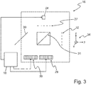
- FIG. 3 shows details of another embodiment of a headlight according to the invention.
- the illumination of the second liquid-crystal matrix element region 30 takes place via a mirror 39.
- the mirror 39 is preferably designed such that it reflects both polarization directions s and p equally well and does not change the two polarization directions during the reflection.
- the distances between the two Liquid crystal matrix element regions 28 and 30 of the projection optics 32 are in the subject of FIG. 3 different from each other.
- the beam splitter-side focal point of the projection optical system 32 is closer to one of the two liquid crystal matrix element regions 28, 30 than to the respective other liquid crystal matrix element region 30, 28.
- different object widths and hence slightly different magnification factors result for the two liquid crystal matrix element regions 28, 30 through the projection optics 32 taking place picture.
- liquid crystal matrix element regions and particularly LCoS regions, have a very large number of pixels (e.g., several hundred thousand), this undesirable effect of different magnification factors can be compensated by adjusting the object size on the liquid crystal matrix element regions.
- FIG. 4 Figure 12 illustrates the image of the surface of the liquid crystal matrix element areas in the headlamp illumination zone of the headlamp.
- the FIG. 4 shows left in the figure part a), the surface regions 28 ', 30' of the two Liquid crystal matrix element regions 28, 30, in which the polarization is rotated, in the ps plane and on the right in the figure part b), the overlap of their two images 28 ", 30" after their projection through the projection optics 32 in the illumination zone.
- a rectangular area should be illuminated in exactly the same position as overlapping contributions 28 ", 30" of both polarization directions.
- the individual pixels of the liquid crystal matrix element regions 28, 30 are switched so that the polarization in the outer region is not rotated and is rotated in the inner regions.
- the outer area is in the FIG. 4 in each case the difference of the surfaces 30 and 30 'as well as 28 and 28'. Only light from the areas where the polarization is rotated is transmitted or reflected by the beam splitter to the projection optics.
- the liquid crystal matrix element region that is imaged into the illumination zone with the larger magnification factor is reduced by a corresponding drive of its outer pixels on the liquid crystal matrix element region. In the example shown, this is the liquid crystal matrix element region 28.
- the then resulting regions 28 ', 30' of different size on the liquid crystal matrix element regions are then imaged by the projection optics so that their images 28 ", 30" in the illumination zone merge into each other in a positionally overlapping manner.
- the degree of polarization of this light distribution by electronic control of the pixels of the liquid crystal matrix element areas are adjusted. If, for example, the pixels of one of the two liquid-crystal matrix element regions 28, 30 are switched such that the light reflected by them is not directed by the beam splitter to the projection optics, then a nearly one hundred percent polarized light distribution results from the respective other of the two liquid-crystal matrix element regions.
- the embodiment of the FIG. 3 requires a deflection mirror 39 between one of the two liquid crystal matrix element regions 28, 30 and the beam splitter 26.
- this principal disadvantage has the advantage that this embodiment does not require two different liquid crystal matrix element region components since the liquid crystal matrix element regions are arranged here in a single plane and therefore can be realized as subregions of a single liquid crystal matrix element area component.
- the different magnification factors which result in this example from the different optical path lengths between the projection optics 32 on the one side and one of the two liquid crystal matrix element regions 28, 30 on the other side can be achieved by arranging the two liquid crystal matrix element regions 28, 30 in mutually offset planes be avoided.
- the two liquid-crystal element regions are arranged in different planes with pixel surfaces arranged parallel to one another. It is preferred that a perpendicular to the Pixel surface lying distance between the two liquid crystal element areas is the same as an average distance of the deflecting mirror 39 from the beam splitter 26.
- the pixel surfaces of the liquid crystal matrix element areas are then offset in the z-direction just offset so far that the optical path lengths of the reflected light there are the same. In this determination of the distance then the two liquid crystal element regions are equidistant from the projection lens. As a result, both areas are imaged by the projection optics 32 with the same magnification factor in the front of the headlight illumination zone.
- this embodiment then requires two different liquid crystal matrix element region components, since the liquid crystal matrix element regions are not arranged in a single plane and therefore can not be realized as partial regions of a single liquid crystal matrix element region component.
- the projection optics 32 is a projection lens, which is represented in these figures by its main plane shown in dashed lines.
- FIG. 5 shows an embodiment in which instead of the projection lens, a reflector 40 is used as projection optics 32.
Landscapes
- Engineering & Computer Science (AREA)
- General Engineering & Computer Science (AREA)
- Chemical & Material Sciences (AREA)
- Crystallography & Structural Chemistry (AREA)
- Liquid Crystal (AREA)
- Non-Portable Lighting Devices Or Systems Thereof (AREA)
Abstract
Description
- Die vorliegende Erfindung betrifft einen Kraftfahrzeugscheinwerfer nach dem Oberbegriff des Anspruchs 1.
- Ein solcher Scheinwerfer ist aus der
DE 10 2013 113 807 A1 bekannt. Flüssigkristallmatrixbauteile werden als Display (LCD), aber auch in Videoprojektoren verwendet. Bei Verwendung in Scheinwerfern bilden die dort herrschenden Umgebungsbedingungen, wie zum Beispiel stark wechselnde Temperaturen, zu überwindende Anwendungshindernisse. Ein weiterer Nachteil besteht in einem eher schwach ausgeprägten Kontrastverhältnis zwischen leuchtenden und nicht leuchtend eingestellten Matrixelementen. - Nachteilig ist auch, dass die Funktion der Flüssigkristallmatrixelemente als in ihrer Helligkeit steuerbare Segmente einer Lichtaustrittsfläche des Flüssigkristallmatrixbauteils eine Beleuchtung mit linear polarisiertem Licht voraussetzt. Licht üblicher Lichtquellen ist zunächst nicht polarisiert und weist zwei Anteile zueinander orthogonaler Polarisationsrichtungen auf. Bei der Verwendung von Flüssigkristallmatrixbauteilen wird das Licht, bevor es auf das Flüssigkristallmatrixbauteil auftrifft, polarisiert. Die Polarisation erfolgt dabei in der Regel durch einen Polarisationsfilter, der nur einen der beiden Anteile durchlässt und der den anderen Anteil absorbiert. Bei einer Beleuchtung des Flüssigkristallmatrixbauteils mit herkömmlichen Lichtquellen geht daher etwa 50 % des Lichtes verloren.
- Aus der
DE 10 2013 113 807 A1 ist es bekannt, beide Anteile zur Erzeugung einer Lichtverteilung zu nutzen. - Diese Schrift zeigt einen Kraftfahrzeugscheinwerfer mit einer Lichtquelle, einem polarisierenden Strahlteiler, der in einem von der Lichtquelle ausgehenden Lichtbündel angeordnet ist und der das von der Lichtquelle her einfallende Licht in ein erstes Teilbündel und ein zweites Teilbündel aufteilt, wobei das Licht des ersten Teilbündels eine erste Polarisationsrichtung aufweist und eine erste Hauptpropagationsrichtung aufweist, und wobei das Licht des zweiten Teilbündels eine zweite Polarisationsrichtung und eine zweite Hauptpropagationsrichtung aufweist, und mit einem ersten reflektierenden Flüssigkristallmatrixelementbereich, dessen Einfluss auf die Polarisationsrichtung des reflektierten Lichtes steuerbar ist, und mit einem zweiten reflektierenden Flüssigkristallmatrixelementbereich dessen Einfluss auf die Polarisationsrichtung des reflektierten Lichtes steuerbar ist. Die Flüssigkristallmatrixelementbereiche werden in Transmission betrieben.
- Der aus der
DE 10 2013 113 807A1 bekannte Scheinwerfer benötigt für jede Polarisationsrichtung eine eigene Projektionsoptik. Jede der beiden Projektionsoptiken überträgt polarisiertes Licht. Scheinwerfer sollen in der Regel Lichtverteilungen erzeugen, die aus unpolarisiertem Licht bestehen. Damit wird eventuell eine zusätzliche Vorrichtung zur Depolarisierung erforderlich. Da zwei Projektionsoptiken erforderlich sind, ergibt sich eine Verdopplung der Lichtaustrittsfläche und damit auch eine Halbierung der Leuchtdichte gegenüber einer Lösung, die nur eine Projektionsoptik erfordert. - Der bekannte Scheinwerfer ist ein sogenannter Matrixscheinwerfer, bei dem die Helligkeit einzelner Pixel des Flüssigkristallelements steuerbar ist. Allgemein erlauben Matrixscheinwerfer in der Automobiltechnik eine dynamische Anpassung der Lichtverteilung der Frontscheinwerfer an wechselnde Umgebungsbedingungen. Beispielsweise können bei Nachtfahrt mit Fernlicht einzelne Teilbereiche der Lichtverteilung abgedunkelt werden, so dass ein entgegenkommendes Fahrzeug trotz eingeschaltetem Fernlicht nicht geblendet wird. Außer mit Flüssigkristalldisplays können solche Scheinwerfer zum Beispiel auch mit Mikrospiegeln (z.B.
DE 10 2013 113807 A1 ,EP 2 813 395 A1 ) realisiert werden. Nachteilig bei diesen Konzepten sind die hohen Kosten für die Mikrospiegel. - Die Aufgabe der vorliegenden Erfindung besteht darin, einen Scheinwerfer der eingangs genannten Art anzugeben, der eine kleinere Lichtaustrittsfläche benötigt und eine größere Leuchtdichte besitzt und der auch ohne zusätzliche Depolarisatoren dazu in der Lage ist, eine im Wesentlichen aus unpolarisiertem Licht bestehende Lichtverteilung zu erzeugen.
- Diese Aufgabe wird mit den Merkmalen des Anspruchs 1 gelöst. Von dem Stand der Technik nach der
DE 10 2013 113 807 A1 unterscheidet sich die vorliegende Erfindung dadurch, dass der erste Flüssigkristallmatrixelementbereich in dem ersten Teilbündel so angeordnet ist, dass er vom Strahlteiler her einfallendes Licht zum Strahlteiler zurückreflektiert, und dass der zweite Flüssigkristallmatrixelementbereich in dem zweiten Teilbündel so angeordnet ist, dass er vom Strahlteiler her einfallendes Licht zum Strahlteiler zurückreflektiert. Die Flüssigkristallmatrixelementbereiche werden bei der Erfindung in Reflexion betrieben. Geeignete Flüssigkristallbauteile sind zum Beispiel aus der Veröffentlichung "Optical Imaging and Metrology", edited by W.Osten and N.Reingand, 2012 Wiley-VCH Verlag bekannt. - Das von den Flüssigkristallmatrixelementbereichen zurückreflektierte Licht wird vom Strahlteiler vereint und mittels einer Projektionsoptik in die Abstrahlrichtung projiziert. Die Flüssigkristallmatrixelementbereiche haben vor allem die Aufgabe, das einfallende Licht pixelweise gemäß der geforderten Lichtfunktion zu modulieren.
- Eine bevorzugte Ausgestaltung zeichnet sich dadurch aus, dass die beiden Flüssigkristallmatrixelementbereiche parallel zueinander ausgerichtet sind, und dass zwischen dem zweiten Flüssigkristallmatrixelementbereich und dem Strahlteiler ein Umlenkspiegel angeordnet ist.
- Bevorzugt ist auch, dass die beiden Flüssigkristallmatrixelementbereiche in derselben Ebene angeordnet sind.
- Eine weitere bevorzugte Ausgestaltung zeichnet sich dadurch aus, dass die beiden Flüssigkristallmatrixelementbereiche aneinander angrenzen und zu demselben Bauelement gehören.
- Ferner ist bevorzugt, dass die einzelnen Pixel der Flüssigkristallmatrixelementbereiche so angesteuert werden, dass die Polarisation des an ihnen reflektierten Lichtes in einem äußeren Bereich nicht gedreht wird und in einem inneren Bereich gedreht wird und dass derjenige innere Bereich, der mit dem einem größeren Vergrößerungsfaktor in eine Beleuchtungszone des Scheinwerfers abgebildet wird, kleiner ist als derjenige innere Bereich, der mit dem einem größeren Vergrößerungsfaktor in eine Beleuchtungszone des Scheinwerfers abgebildet wird.
- Bevorzugt ist auch, dass der erste Flüssigkristallmatrixelementbereich zu einem ersten Bauelement gehört, und dass der zweite Flüssigkristallmatrixelementbereich zu einem zweiten, vom ersten Bauelement separaten Bauelement gehört.
- Eine weitere bevorzugte Ausgestaltung zeichnet sich dadurch aus, dass die beiden Flüssigkristallmatrixelementbereiche parallel zueinander in verschiedenen, zueinander parallelen Ebenen versetzt zueinander angeordnet sind.
- Bevorzugt ist auch, dass die beiden Flüssigkristallmatrixelementbereiche parallel zueinander in verschiedenen, zueinander parallelen Ebenen soweit versetzt zueinander angeordnet sind, und dass ein senkrecht zu den Pixeloberflächen liegender Abstand zwischen den beiden Flüssigkristallelementbereichen genauso groß ist wie ein mittlerer Abstand des Umlenkspiegels vom Strahlteiler.
- Bevorzugt ist auch, dass die beiden Flüssigkristallmatrixelementbereiche einen rechten Winkel miteinander einschließen, wobei eine Oberfläche des Flüssigkristallmatrixelementbereichs einer ersten Seite des Strahlteilers zugewandt ist und wobei eine Oberfläche des zweiten Flüssigkristallmatrixelementbereichs einer zweiten Oberfläche des Strahlteilers zugewandt ist.
- Bevorzugt ist auch, dass die Flüssigkristallmatrixelementbereiche so angeordnet sind, dass das vom Strahlteiler her einfallende Licht lotrecht auf die Flüssigkristallmatrixelementbereiche einfällt und damit auch lotrecht reflektiert wird.
- Eine bevorzugte Ausgestaltung zeichnet sich durch eine Projektionsoptik aus, die im Strahlengang des von den Flüssigkristallmatrixelementbereichen reflektierten Lichtes hinter dem Strahlteiler angeordnet ist.
- Bevorzugt ist auch, dass ein strahlteilerseitiger Brennpunkt der Projektionsoptik in der Nähe der Oberflächen der Flüssigkristallmatrixelementbereiche liegt.
- Eine weitere bevorzugte Ausgestaltung zeichnet sich dadurch aus, dass ein erstes optisches Element zwischen der Lichtquelle und dem Strahlteiler angeordnet ist, und dass das erste optische Element dazu eingerichtet ist, von der Lichtquelle ausgehendes Licht zu parallelisieren.
- Ferner ist bevorzugt, dass das erste optische Element eine Linse, ein Reflektor oder eine katadioptrische Vorsatzoptik ist.
- Bevorzugt ist auch, dass der polarisierende Strahlteiler aus zwei prismatischen Hälften besteht.
- Bevorzugt ist auch, dass der Strahlteiler ein Dünnschichtpolarisator ist.
- Weitere Vorteile ergeben sich aus den abhängigen Ansprüchen, der Beschreibung und den beigefügten Figuren.
- Es versteht sich, dass die vorstehend genannten und die nachstehend noch zu erläuternden Merkmale nicht nur in der jeweils angegebenen Kombination, sondern auch in anderen Kombinationen oder in Alleinstellung verwendbar sind, ohne den Rahmen der vorliegenden Erfindung zu verlassen.
- Ausführungsbeispiele der Erfindung sind in den Zeichnungen dargestellt und werden in der nachfolgenden Beschreibung näher erläutert. Dabei bezeichnen gleiche Bezugszeichen in verschiedenen Figuren jeweils gleiche oder zumindest ihrer Funktion nach vergleichbare Elemente. Es zeigen, jeweils in schematischer Form:
- Figur 1
- das technische Umfeld der Erfindung in Form eines Scheinwerfers eines Kraftfahrzeugs;
- Figur 2
- Einzelheiten eines Ausführungsbeispiels eines erfindungsgemäßen Scheinwerfers;
- Figur 3
- Einzelheiten eines weiteren Ausführungsbeispiels eines erfindungsgemäßen Scheinwerfers;
- Figur 4
- Einzelheiten eines weiteren Ausführungsbeispiels eines erfindungsgemäßen Scheinwerfers; und
- Figur 5
- ein Ausführungsbeispiel mit einem Reflektor als Projektionsoptik.
- Im Einzelnen zeigt die
Figur 1 einen Scheinwerfer 10 eines Kraftfahrzeugs. Der Scheinwerfer 10 weist ein Gehäuse 12 auf, dessen Lichtaustrittsöffnung von einer transparenten Abdeckscheibe 14 abgedeckt wird. Im Inneren des Gehäuses 12 befindet sich ein Lichtmodul 16 und ein Steuergerät 18. - Das Steuergerät 18 ist dazu eingerichtet, insbesondere dazu programmiert, die Funktion des Lichtmoduls 16 in Abhängigkeit von Signalen eines Fahrerwunschgebers 20 oder eines übergeordneten Lichtsteuergeräts 22 des Kraftfahrzeugs zu steuern. Der Fahrerwunschgeber 20 ist zum Beispiel ein Lichtschalter des Kraftfahrzeuges.
- Die
Figur 2 zeigt Einzelheiten eines Merkmale der Erfindung aufweisenden Lichtmoduls 16 eines erfindungsgemäßen Scheinwerfers. Das Lichtmodul 16 weist eine Lichtquelle 24, einen polarisierenden Strahlteiler 26, einen ersten reflektierenden Flüssigkristallmatrixelementbereich 28, einen zweiten reflektierenden Flüssigkristallmatrixelementbereich 30, und eine Projektionsoptik 32 auf. - Die Lichtquelle 24 weist bevorzugt wenigstens eine, bevorzugt jedoch mehrere Leuchtdioden auf. Die Leuchtdioden geben Licht weißer Farbe ab, wie es für Kraftfahrzeugscheinwerfer zulässig ist.
- Ein von der Lichtquelle 24 ausgehendes Lichtbündel 25 aus unpolarisiertem Licht wird bevorzugt zunächst von einem ersten optischen Element 27 parallelisiert. Das erste optische Element 27 ist bevorzugt als Linse oder als Reflektor oder als katadioptrische Vorsatzoptik verwirklicht. Das von dem ersten optischen Element 27 ausgehende parallelisierte Lichtbündel 29 fällt auf den polarisierenden Strahlteiler 26 ein. Das erste optische Element 27 befindet sich zwischen der Lichtquelle 24 und dem Strahlteiler 26.
- Der Strahlteiler 26 ist hier schematisch als Strahlteilerwürfel dargestellt, der aus zwei prismatischen Hälften besteht, die in der Zeichnungsebene jeweils die Form eines rechtwinkligen und gleichseitigen Dreiecks besitzen und die längs ihrer dem jeweiligen rechten Winkel gegenüberliegenden Basisflächen zu einem Würfel zusammengesetzt sind. Die Basisflächen eines solchen Würfels sind dann die strahlteilenden Flächen 31. Abweichend von dieser Ausgestaltung ist der Strahlteiler 26 bevorzugt ein Dünnschichtpolarisator.
- In der
Figur 2 erscheinen die strahlteilenden Flächen 31 des Strahlteilers 26 als Linie, die in einer p-z-Ebene eines rechtwinklig-rechtshändigen Koordinatensystems 34 liegt. Das Koordinatensystem 34 weist eine s-Achse, eine p-Achse und eine z-Achse auf, wobei die Achsen orthogonal zueinander sind. Die Form und Lage der strahlteilenden Fläche 31 ergibt sich bei dieser Darstellung durch Verschiebung der die strahlteilende Fläche 31 darstellenden Linie in der S-Richtung. - Eine Lichteinfallsebene, in der letztlich von der Lichtquelle 24 ausgehendes Licht auf den Strahlteiler 26 einfällt, ist mit der Zeichnungsebene identisch und ist daher parallel zu einer p-z-Ebene. Eine solche Lichteinfallsebene wird von der Richtung des einfallenden Strahls und dem Lot der ebenen Fläche, auf die der Strahl einfällt, definiert.
- Das einfallende, unpolarisierte Licht 29 weist einen ersten Anteil auf, der parallel zu der p-z-Lichteinfallsebene polarisiert ist. Dieser Anteil wird im Folgenden auch als p-Anteil bezeichnet. Seine Polarisationsrichtung liegt in der Zeichnungsebene.
- Das einfallende, unpolarisierte Licht 29 weist darüber hinaus einen zweiten Anteil auf, der senkrecht zu der p-z-Lichteinfallsebene polarisiert ist. Dieser Anteil wird im Folgenden auch als s-Anteil bezeichnet. Seine Polarisationsrichtung steht senkrecht auf der Zeichnungsebene.
- Der polarisierende Strahlteiler 26 hat die Eigenschaft, für einen der beiden Anteile transparent zu sein und den anderen Anteil zu reflektieren. Ohne Beschränkung der Allgemeinheit soll im Folgenden davon ausgegangen werden, dass der polarisierende Strahlteiler 26 für den p-Anteil transparent ist und den s-Anteil reflektiert. Das bedeutet, dass der p-Anteil durch die strahlteilenden Flächen 31 hindurchtritt und dass der s-Anteil an den strahlteilenden Flächen 31 reflektiert wird. In einer alternativen Ausgestaltung ist der polarisierende Strahlteiler 26 für den s-Anteil transparent und reflektiert den s-Anteil.
- Der polarisierende Strahlteiler 26 teilt das letztlich von der Lichtquelle 24 her direkt oder, wenn ein erstes optisches Element 27 vorhanden ist, über das erste optische Element 27 einfallende Licht 29 in ein erstes Teilbündel 36 und ein zweites Teilbündel 38 auf.
- Das Licht des ersten Teilbündels 36 weist eine erste Polarisationsrichtung (hier parallel zur Einfallsebene, daher als p-Richtung bezeichnet) und eine erste Hauptpropagationsrichtung auf. Dieses Teilbündel 36 tritt durch die strahlteilenden Flächen 31 hindurch. Die erste Hauptpropagationsrichtung weist zu dem ersten Flüssigkristallmatrixelementbereich 28, der damit mit dem p-Anteil beleuchtet wird.
- Das Licht des zweiten Teilbündels 38 weist eine zweite Polarisationsrichtung (hier senkrecht zur Einfallsebene, daher als s-Richtung bezeichnet) und eine zweite Hauptpropagationsrichtung auf. Dieses Teilbündel 38 wird an den strahlteilenden Flächen reflektiert. Nach der Reflexion weist die zweite Hauptpropagationsrichtung zu dem zweiten Flüssigkristallmatrixelementbereich 30, der damit mit dem s-Anteil beleuchtet wird.
- Der erste Flüssigkristallmatrixelementbereich 28 ist in dem ersten Teilbündel 36 so angeordnet, dass er vom Strahlteiler 26 her einfallendes Licht zum Strahlteiler 26 zurückreflektiert. Der erste Flüssigkristallmatrixelementbereich 28 ist also senkrecht zum einfallenden Teilbündel 36 ausgerichtet. Der zweite Flüssigkristallmatrixelementbereich 30 ist in dem zweiten Teilbündel 38 so angeordnet, dass er vom Strahlteiler 26 her einfallendes Licht zum Strahlteiler 26 zurückreflektiert. Der zweite Flüssigkristallmatrixelementbereich 30 ist also senkrecht zum einfallenden Teilbündel 38 ausgerichtet. Jeder Flüssigkristallmatrixelementbereich 28, 30 ist bevorzugt als LCoS-Bauelement (LCoS = Liquid Crystal on Silicon) oder Teilbereich eines zusammenhängenden LCoS-Bauelements verwirklicht.
- Der Einfluss des ersten reflektierenden Flüssigkristallmatrixelementbereichs 30 auf die Polarisationsrichtung des an ihm reflektierten Lichtes ist vom Steuergerät 18 pixelweise steuerbar. Durch den Steuerungseingriff wird die Polarisationsrichtung des reflektierten Strahls mehr oder weniger gedreht. In der
Figur 2 weist der erste Flüssigkristallmatrixelementbereich 28 in der p-Richtung 10 Pixel auf, so dass sich bei gleicher Pixelzahl in der s-Richtung eine Zahl von 100 Pixeln ergeben würde. In der Realität kann die Zahl der Pixel auch wesentlich höher sein und in der Größenordnung von mehreren hunderttausend liegen. - Analog dazu ist auch der Einfluss des zweiten reflektierenden Flüssigkristallmatrixelementbereichs 30 auf die Polarisationsrichtung des an ihm reflektierten Lichtes vom Steuergerät 18 pixelweise steuerbar. In der
Figur 2 weist der zweite Flüssigkristallmatrixelementbereich 30 in der z-Richtung 10 Pixel auf, so dass sich bei gleicher Pixelzahl in der s-Richtung eine Zahl von 100 Pixeln ergeben würde. Auch hier gilt, dass die Zahl der Pixel in der Realität wesentlich größer sein kann. Diese Zahl wird im Allgemeinen der Zahl der Pixel des ersten Flüssigkristallmatrixelementbereichs 28 entsprechen. - An dieser Stelle sei erwähnt, dass der Reflexionsgrad der Flüssigkristallmatrixelementbereiche zusätzlich vom Einfallswinkel des auf die Pixel auftreffenden Lichtes abhängig ist. Aus diesem Grunde ist die mit dem ersten optischen Element 27 erzielte Parallelisierung vorteilhaft, da sie dazu führt, dass die Lichtstrahlen eines Bündels jeweils mit dem gleichen Einfallswinkel auf die Pixel auftreffen. Der Auftreffwinkel zum Lot ist dabei bevorzugt Null Grad. Dann ergibt sich zwanglos eine Richtungsumkehr bei der in den Pixeln erfolgenden Reflexion, die das in den Pixeln reflektierte Licht ohne weitere Umlenkungen wieder zu dem Strahlteiler zurückführt.
- Für die folgende Erläuterung wird angenommen, dass die gekreuzt dargestellten Pixel vom Steuergerät so angesteuert werden, dass sie die Polarisation des auf sie einfallenden Lichtes um 90° drehen, so dass auf diese Pixel einfallendes Licht, das in p-Richtung polarisiert ist, aus den mit Kreuzen versehenen Pixeln als in s-Richtung polarisiertes Licht austritt. Analog soll für die gekreuzt dargestellten Pixel gelten, dass auf die Pixel einfallendes Licht, das in s-Richtung polarisiert ist, aus diesen Pixeln als in p-Richtung polarisiertes Licht austritt.
- Die nicht gekreuzt dargestellten Pixel sollen dagegen die Polarisationsrichtung nicht verändern, so dass die Polarisationsrichtung des aus diesen Pixeln austretenden Lichtes der Polarisationsrichtung des auf diese Pixel einfallenden Lichtes entspricht.
- Im Ergebnis führt dies dazu, dass das an den gekreuzt dargestellten Pixeln des zweiten Flüssigkeitskristallmatrixelementbereichs 30 reflektierte Licht, das zum Strahlteiler 26 zurückreflektiert wird, dort als in p-Richtung polarisiertes Licht auftrifft und als solches vom Strahlteiler in p-Richtung transmittiert wird.
- Analog dazu trifft das an den gekreuzt dargestellten Pixeln des ersten Flüssigkeitskristallmatrixelementbereichs 28 reflektierte Licht, das direkt zum Strahlteiler zurückreflektiert wird, dort als in s-Richtung polarisiertes Licht auf und wird als solches vom Strahlteiler in die p-Richtung reflektiert. Die beiden Lichtanteile werden also vom Strahlteiler 26 wieder zu einem Lichtbündel zusammengeführt. Dieses Lichtbündel wird bevorzugt von einer Projektionsoptik 32 in eine vor dem Scheinwerfer liegende Beleuchtungszone verteilt.
- Die in der
Figur 2 nicht gekreuzt dargestellten Pixel der beiden Flüssigkristallmatrixelementbereiche 28, 30 sind Pixel, die vom Steuergerät 18 so angesteuert werden, dass sie die Polarisation des dort auftreffenden Lichtes nicht drehen. Das hat zur Folge, dass die an den nicht gekreuzt dargestellten Pixeln des ersten Flüssigkristallmatrixelementbereichs 28 reflektierten Strahlen in dem dargestellten Ausführungsbeispiel mit einer p-Polarisierung auf den Strahlteiler auftreffen und daher nach der Reflexion am ersten Flüssigkristallmatrixelementbereich 28 in Richtung der Lichtquelle 24 transmittiert werden. Diese Lichtstrahlen tragen also nicht zu der Lichtverteilung in der Beleuchtungszone vor dem Scheinwerfer bei. - Analog dazu werden die an den nicht gekreuzt dargestellten Pixeln des zweiten Flüssigkristallmatrixelementbereichs 30 reflektierten Strahlen in dem dargestellten Ausführungsbeispiel mit einer s-Polarisierung auf den Strahlteiler 26 auftreffen und daher in Richtung der Lichtquelle 24 reflektiert werden. Auch diese Lichtstrahlen tragen also nicht zu der Lichtverteilung in der Beleuchtungszone vor dem Scheinwerfer bei.
- Ein strahlteilerseitiger Brennpunkt der Projektionsoptik 32 liegt bevorzugt in der Nähe der Oberflächen der Flüssigkristallmatrixelementbereiche 28, 30. Unter einer Nähe wird dabei ein Abstand des Brennpunktes zu den Oberflächen 28, 30 verstanden, der zwischen 0 und 10% der Brennweite der Projektionsoptik 32 beträgt. Dann bildet die Projektionsoptik 32 das sich dort in der Umgebung des Brennpunktes einstellende Beleuchtungsmuster des vom Strahlteiler 26 zur Projektionsoptik transmittierten Lichtanteils als Lichtverteilung in die genannte Beleuchtungszone ab. Das sich in der Beleuchtungszone vor dem Scheinwerfer einstellende Beleuchtungsmuster ist daher durch eine Ansteuerung der Pixel mit einer durch die Pixelgröße gegebenen Feinheit formbar.
- Durch eine Änderung einer Ansteuerung der Pixel durch das Steuergerät 18 lassen sich daher verschiedene Lichtverteilungen mit steuerbar verteilten hellen und dunklen Bereichen in der Beleuchtungszone vor dem Scheinwerfer erzeugen. Da die beiden verschieden polarisierten Anteile von dem Strahlteiler 26 wieder zu einem Bündel vereinigt werden, besteht die sich in der Beleuchtungszone einstellende Lichtverteilung im Wesentlichen aus unpolarisiertem Licht. Dies setzt voraus, dass das räumliche Muster der Pixelansteuerung bei beiden Flüssigkristallmatrixelementbereichen gleich oder zumindest ähnlich ist.
- Der zweite Flüssigkristallmatrixelementbereich 30 ist dabei bevorzugt so angeordnet, dass seine Pixeloberfläche senkrecht zu dem vom Strahlteiler 26 her ausgehenden und ohne Umlenkung auf ihn einfallenden Licht ausgerichtet ist. Darüber hinaus ist der zweite Flüssigkristallmatrixelementbereich 30 bevorzugt so angeordnet, dass der Abstand seiner Pixeloberfläche vom Strahlteiler 26 genauso groß ist wie der Abstand der Pixeloberfläche des ersten Flüssigkristallmatrixelementbereichs 28 vom Strahlteiler 26.
- Dann ergeben sich bei diesem Ausführungsbeispiel gleiche Vergrößerungsfaktoren für die durch die Projektionsoptik 32 erfolgende Abbildung der Pixeloberflächen des ersten Flüssigkristallmatrixelementbereichs und des zweiten Flüssigkristallmatrixelementbereichs.
- Im Unterschied zu einem weiter unten beschriebenen Ausführungsbeispiel benötigt dieses Ausführungsbeispiel keinen Umlenkspiegel zwischen einem der beiden Flüssigkristallmatrixelementbereiche 28, 30 und dem Strahlteiler 26. Allerdings benötigt dieses Ausführungsbeispiel zwei verschiedene Flüssigkristallmatrixelementbereichs-Bauteile, da die Flüssigkristallmatrixelementbereiche 28, 30 nicht in einer einzigen Ebene angeordnet sind und daher nicht als Teilbereiche eines einzigen Flüssigkristallmatrixelementbereichs-Bauteils verwirklicht werden können.
- In einer bevorzugten Ausgestaltung weist das von der Lichtquelle 24 her auf den Strahlteiler 26 auftreffende weiße Licht quer zu seiner Ausbreitungsrichtung ein Intensitätsprofil mit einem Maximum auf, das im Bereich einer mittleren Abstrahlrichtung liegt und das zu den Seiten hin, also mit zunehmendem Abstand von der mittleren Abstrahlrichtung, kontinuierlich niedriger wird. Dadurch ergibt sich in der letztlich in einer vom Scheinwerfer beleuchteten Beleuchtungszone vor dem Kraftfahrzeug ein zu den Seiten weich, d.h. ohne scharfe Hell-Dunkel-Grenze auslaufende Helligkeit, was die Bildung einer für Kraftfahrzeuge üblichen Lichtverteilung begünstigt.
- Prinzipiell ist es erwünscht, dass die Projektionsoptik 32 die Oberfläche der beiden Flüssigkristallmatrixelementbereiche 28, 30 und deren Pixel scharf und möglichst positionsgenau überlappend in die Beleuchtungszone abbildet, so dass das Bild von jedem Pixel möglichst weitgehend durch unpolarisiertes Licht beleuchtet wird.
- Die
Figur 3 zeigt Einzelheiten eines weiteren Ausführungsbeispiels eines erfindungsgemäßen Scheinwerfers. Bei dem Gegenstand derFigur 3 erfolgt die Beleuchtung des zweiten Flüssigkristallmatrixelementbereichs 30 über einen Spiegel 39. Der Spiegel 39 ist bevorzugt so ausgestaltet, dass er beide Polarisationsrichtungen s und p gleich gut reflektiert und die beiden Polarisationsrichtungen bei der Reflexion nicht verändert. Die Abstände der beiden Flüssigkristallmatrixelementbereiche 28 und 30 von der Projektionsoptik 32 sind bei dem Gegenstand derFigur 3 verschieden voneinander. - Im Allgemeinen liegt dann der strahlteilerseitige Brennpunkt der Projektionsoptik 32 näher an einem der beiden Flüssigkristallmatrixelementbereiche 28, 30 als an dem jeweils anderen Flüssigkristallmatrixelementbereich 30, 28. Als Folge ergeben sich für die beiden Flüssigkristallmatrixelementbereiche 28, 30 unterschiedliche Gegenstandsweiten und damit auch leicht unterschiedliche Vergrößerungsfaktoren bei der durch die Projektionsoptik 32 erfolgenden Abbildung.
- Da Flüssigkristallmatrixelementbereiche und insbesondere LCoS-Bereiche eine sehr große Zahl von Pixeln besitzen (z.B. mehrere hunderttausend), kann dieser unerwünschte Effekt unterschiedlicher Vergrößerungsfaktoren durch ein Anpassen der Objektgröße auf den Flüssigkristallmatrixelementbereichen kompensiert werden.
- Für eine Erläuterung der Kompensation soll zunächst angenommen werden, dass der in der
Figur 3 näher an der Projektionsoptik 32 liegende erste Flüssigkristallmatrixelementbereich 28 ohne kompensierende Maßnahmen mit einem größeren Vergrößerungsfaktor in die Beleuchtungszone abgebildet werden würde als der weiter von der Projektionsoptik 32 entfernt liegende zweite Flüssigkristallmatrixelementbereich 38. -
Figur 4 veranschaulicht die Abbildung der Oberfläche der Flüssigkristallmatrixelementbereiche in die vor dem Fahrzeug liegenden Beleuchtungszone des Scheinwerfers. DieFigur 4 zeigt links in dem Figurenteil a) die Oberflächenbereiche 28', 30' der beiden Flüssigkristallmatrixelementbereiche 28, 30, in denen die Polarisation gedreht wird, in der p-s-Ebene und rechts im Figurenteil b) die Überlappung ihrer beiden Bilder 28", 30" nach ihrer durch die Projektionsoptik 32 erfolgenden Abbildung in die Beleuchtungszone. In dem in der Beleuchtungszone liegenden Bildbereich soll zum Beispiel ein rechteckiger Bereich positionsgenau überlappend mit Beiträgen 28", 30" beider Polarisationsrichtungen beleuchtet werden. - Dazu werden die einzelnen Pixel der Flüssigkristallmatrixelementbereiche 28, 30 so geschaltet, dass die Polarisation in dem äußeren Bereich nicht gedreht wird und in den inneren Bereichen gedreht wird. Der äußere Bereich ist in der
Figur 4 jeweils die Differenz der Flächen 30 und 30' sowie 28 und 28'. Nur Licht aus den Bereichen, in denen die Polarisation gedreht wird, wird vom Strahlteiler zur Projektionsoptik durchgelassen oder reflektiert. Derjenige Flüssigkristallmatrixelementbereich, der mit dem größeren Vergrößerungsfaktor in die Beleuchtungszone abgebildet wird, wird durch eine entsprechende Ansteuerung seiner äußeren Pixel auf dem Flüssigkristallmatrixelementbereich verkleinert. Im dargestellten Beispiel ist dies der Flüssigkristallmatrixelementbereich 28. - Die dann resultierenden Bereiche 28', 30' unterschiedlicher Größe auf den Flüssigkristallmatrixelementbereichen werden dann durch die Projektionsoptik so abgebildet, dass ihre Bilder 28", 30" in der Beleuchtungszone positionsgenau überlappend miteinander verschmelzen.
- Für den Fall, dass eine polarisierte Lichtverteilung in der Beleuchtungszone erzeugt werden soll, kann der Polarisationsgrad dieser Lichtverteilung durch elektronische Ansteuerung der Pixel der Flüssigkristallmatrixelementbereiche angepasst werden. Werden zum Beispiel die Pixel eines der beiden Flüssigkristallmatrixelementbereiche 28, 30 so geschaltet, dass das von ihnen reflektierte Licht vom Strahlteiler nicht zu der Projektionsoptik gerichtet wird, ergibt sich durch den jeweils anderen der beiden Flüssigkristallmatrixelementbereiche eine nahezu einhundertprozentig polarisierte Lichtverteilung.
- Das Ausführungsbeispiel nach der
Figur 3 benötigt einen Umlenkspiegel 39 zwischen einem der beiden Flüssigkristallmatrixelementbereiche 28, 30 und dem Strahlteiler 26. Dieser prinzipielle Nachteil geht aber mit dem Vorteil einher, dass dieses Ausführungsbeispiel keine zwei verschiedenen Flüssigkristallmatrixelementbereichs-Bauteile benötigt, da die Flüssigkristallmatrixelementbereiche hier in einer einzigen Ebene angeordnet sind und daher als Teilbereiche eines einzigen Flüssigkristallmatrixelementbereichs-Bauteils verwirklicht werden können. - Die unterschiedlichen Vergrößerungsfaktoren, die bei diesem Beispiel aus den unterschiedlichen optischen Weglängen zwischen der Projektionsoptik 32 auf der einen Seite und jeweils einem der beiden Flüssigkristallmatrixelementbereiche 28, 30 auf der anderen Seite resultieren, können durch eine Anordnung der beiden Flüssigkristallmatrixelementbereiche 28, 30 in zueinander versetzten Ebenen vermieden werden.
- In einem weiteren Ausführungsbeispiel sind die beiden Flüssigkristallelementbereiche dazu in verschieden Ebenen mit parallel zueinander angeordneten Pixeloberflächen angeordnet. Dabei ist bevorzugt, dass ein senkrecht zu den Pixeloberflächen liegender Abstand zwischen den beiden Flüssigkristallelementbereichen genauso groß ist wie ein mittlerer Abstand des Umlenkspiegels 39 vom Strahlteiler 26. Die Pixeloberflächen der Flüssigkristallmatrixelementbereiche sind dann in der z-Richtung gerade soweit versetzt angeordnet, dass die optischen Weglängen des dort reflektierten Lichtes gleich sind. Bei dieser Festlegung des Abstands sind dann die beiden Flüssigkristallelementbereiche gleich weit von der Projektionslinse entfernt angeordnet. Als Folge werden beide Bereiche von der Projektionsoptik 32 mit gleichem Vergrößerungsfaktor in die vor dem Scheinwerfer liegende Beleuchtungszone abgebildet.
- Allerdings benötigt dieses Ausführungsbeispiel dann zwei verschiedene Flüssigkristallmatrixelementbereichs-Bauteile, da die Flüssigkristallmatrixelementbereiche nicht in einer einzigen Ebene angeordnet sind und daher nicht als Teilbereiche eines einzigen Flüssigkristallmatrixelementbereichs-Bauteils verwirklicht werden können.
- Bei dem in den
Figur 2 und3 dargestellten Ausführungsbeispielen ist die Projektionsoptik 32 eine Projektionslinse, die in diesen Figuren durch ihre gestrichelt dargestellte Hauptebene repräsentiert wird. -
Figur 5 zeigt ein Ausführungsbeispiel, bei dem an Stelle der Projektionslinse ein Reflektor 40 als Projektionsoptik 32 verwendet wird.
Claims (16)
- Kraftfahrzeugscheinwerfer (10) mit einer Lichtquelle (24), einem polarisierenden Strahlteiler (26), der in einem von der Lichtquelle (24) ausgehenden Lichtbündel (25) angeordnet ist und der das von der Lichtquelle (24) her einfallende Licht in ein erstes Teilbündel (36) und ein zweites Teilbündel (38) aufteilt, wobei das Licht des ersten Teilbündels (36) eine erste Polarisationsrichtung aufweist und eine erste Hauptpropagationsrichtung aufweist, und wobei das Licht des zweiten Teilbündels (38) eine zweite Polarisationsrichtung und eine zweite Hauptpropagationsrichtung aufweist, und mit einem ersten reflektierenden Flüssigkristallmatrixelementbereich (28), dessen Einfluss auf die Polarisationsrichtung des an ihm reflektierten Lichtes steuerbar ist, und mit einem zweiten reflektierenden Flüssigkristallmatrixelementbereich (30) dessen Einfluss auf die Polarisationsrichtung des an ihm reflektierten Lichtes steuerbar ist, dadurch gekennzeichnet, dass der erste Flüssigkristallmatrixelementbereich (28) in dem ersten Teilbündel (36) so angeordnet ist, dass er vom Strahlteiler (26) her einfallendes Licht zum Strahlteiler (26) zurückreflektiert, und dass der zweite Flüssigkristallmatrixelementbereich (30) in dem zweiten Teilbündel (38) so angeordnet ist, dass er vom Strahlteiler (26) her einfallendes Licht zum Strahlteiler (26) zurückreflektiert.
- Scheinwerfer (10) nach Anspruch 1, dadurch gekennzeichnet, dass die beiden Flüssigkristallmatrixelementbereiche (28, 30) parallel zueinander ausgerichtet sind, und dass zwischen dem zweiten Flüssigkristallmatrixelementbereich (30) und dem Strahlteiler (26) ein Umlenkspiegel (39) angeordnet ist.
- Scheinwerfer (10) nach Anspruch 2, dadurch gekennzeichnet, dass die beiden Flüssigkristallmatrixelementbereiche (28, 30) in derselben Ebene angeordnet sind.
- Scheinwerfer (10) nach Anspruch 3, dadurch gekennzeichnet, dass die beiden Flüssigkristallmatrixelementbereiche (28, 30) aneinander angrenzen und zu demselben Bauelement gehören.
- Scheinwerfer (10) nach Anspruch 3 oder 4, dadurch gekennzeichnet, dass die einzelnen Pixel der Flüssigkristallmatrixelementbereiche 28, 30 so angesteuert werden, dass die Polarisation des an ihnen reflektierten Lichtes in einem äußeren Bereich nicht gedreht wird und in einem inneren Bereich (28', 30') gedreht wird und dass derjenige innere Bereich (28'), der mit dem einem größeren Vergrößerungsfaktor in eine Beleuchtungszone des Scheinwerfers abgebildet wird, kleiner ist als derjenige innere Bereich (30'), der mit dem einem größeren Vergrößerungsfaktor in eine Beleuchtungszone des Scheinwerfers abgebildet wird.
- Scheinwerfer (10) nach einem der vorhergehenden Ansprüche, dadurch gekennzeichnet, dass der erste Flüssigkristallmatrixelementbereich (28) zu einem ersten Bauelement gehört, und der zweite Flüssigkristallmatrixelementbereich (30) zu einem zweiten, vom ersten Bauelement separaten Bauelement gehört.
- Scheinwerfer (10) nach Anspruch 1, dadurch gekennzeichnet, dass die beiden Flüssigkristallmatrixelementbereiche (28, 30) parallel zueinander in verschiedenen, zueinander parallelen Ebenen versetzt zueinander angeordnet sind.
- Scheinwerfer (10) nach Anspruch 7, dadurch gekennzeichnet, dass die beiden Flüssigkristallmatrixelementbereiche (28, 30) parallel zueinander in verschiedenen, zueinander parallelen Ebenen soweit versetzt zueinander angeordnet sind, dass ein senkrecht zu den Pixeloberflächen liegender Abstand zwischen den beiden Flüssigkristallelementbereichen genauso groß ist wie ein mittlerer Abstand des Umlenkspiegels (39) vom Strahlteiler (26).
- Scheinwerfer (10) nach Anspruch 1, dadurch gekennzeichnet, dass die beiden Flüssigkristallmatrixelementbereiche (28, 30) einen rechten Winkel miteinander einschließen, wobei eine Oberfläche des Flüssigkristallmatrixelementbereichs (28) einer ersten Seite des Strahlteilers (26) zugewandt ist und wobei eine Oberfläche des zweiten Flüssigkristallmatrixelementbereichs (30) einer zweiten Oberfläche des Strahlteilers (26) zugewandt ist.
- Scheinwerfer nach einem der vorhergehenden Ansprüche, dass die Flüssigkristallmatrixelementbereiche so angeordnet sind, dass das vom Strahlteiler her einfallende Licht lotrecht auf die Flüssigkristallmatrixelementbereiche einfällt und damit auch lotrecht reflektiert wird.
- Scheinwerfer nach einem der vorhergehenden Ansprüche, gekennzeichnet durch eine Projektionsoptik, die im Strahlengang des von den Flüssigkristallmatrixelementbereichen reflektierten Lichtes hinter dem Strahlteiler angeordnet ist.
- Scheinwerfer (10) nach Anspruch 11, dadurch gekennzeichnet, dass ein strahlteilerseitiger Brennpunkt der Projektionsoptik (32) in der Nähe der Oberflächen der Flüssigkristallmatrixelementbereiche (28, 30) liegt.
- Scheinwerfer (10) nach einem der vorhergehenden Ansprüche, dadurch gekennzeichnet, dass ein erstes optisches Element (27) zwischen der Lichtquelle (24) und dem Strahlteiler (26) angeordnet ist, und dass das erste optische Element (27) dazu eingerichtet ist, von der Lichtquelle (24) ausgehendes Licht zu parallelisieren.
- Scheinwerfer (10) nach Anspruch 13, dadurch gekennzeichnet, dass das erste optische Element (27) eine Linse, ein Reflektor oder eine katadioptrische Vorsatzoptik ist.
- Scheinwerfer (10) nach einem der vorhergehenden Ansprüche, dadurch gekennzeichnet, dass der polarisierende Strahlteiler (26) aus zwei prismatischen Hälften besteht.
- Scheinwerfer (10) nach einem der Ansprüche 1 bis 14, dadurch gekennzeichnet, dass der Strahlteiler (26) ein Dünnschichtpolarisator ist.
Applications Claiming Priority (1)
| Application Number | Priority Date | Filing Date | Title |
|---|---|---|---|
| DE102016102991.2A DE102016102991A1 (de) | 2016-02-19 | 2016-02-19 | Kraftfahrzeug-Scheinwerfer mit einem Flüssigkristalldisplay |
Publications (3)
| Publication Number | Publication Date |
|---|---|
| EP3208531A2 true EP3208531A2 (de) | 2017-08-23 |
| EP3208531A3 EP3208531A3 (de) | 2017-10-25 |
| EP3208531B1 EP3208531B1 (de) | 2020-04-01 |
Family
ID=58094247
Family Applications (1)
| Application Number | Title | Priority Date | Filing Date |
|---|---|---|---|
| EP17156657.3A Active EP3208531B1 (de) | 2016-02-19 | 2017-02-17 | Kraftfahrzeug-scheinwerfer mit einem flüssigkristalldisplay |
Country Status (2)
| Country | Link |
|---|---|
| EP (1) | EP3208531B1 (de) |
| DE (1) | DE102016102991A1 (de) |
Cited By (2)
| Publication number | Priority date | Publication date | Assignee | Title |
|---|---|---|---|---|
| EP3547009A1 (de) * | 2018-03-29 | 2019-10-02 | Valeo Vision | Lichtsignalvorrichtung mit lcd-bildschirm |
| CN112415738A (zh) * | 2020-02-24 | 2021-02-26 | 谷歌有限责任公司 | 可编程注入器栅格板 |
Families Citing this family (2)
| Publication number | Priority date | Publication date | Assignee | Title |
|---|---|---|---|---|
| DE102017109679A1 (de) * | 2017-05-05 | 2018-11-08 | Jos. Schneider Optische Werke Gmbh | Vorrichtung und Verfahren zum Erzeugen einer Ausgangslichtemission und Scheinwerfer |
| CN106939992A (zh) | 2017-05-14 | 2017-07-11 | 上海小糸车灯有限公司 | 一种基于pbs分光器的车灯系统 |
Citations (2)
| Publication number | Priority date | Publication date | Assignee | Title |
|---|---|---|---|---|
| EP2813395A1 (de) | 2013-06-11 | 2014-12-17 | Valeo Vision | Kraftfahrzeug-Scheinwerfer, der eine Laser-Lichtquelle umfasst und Verfahren zur Erzeugung eines Lichtbündel |
| DE102013113807A1 (de) | 2013-12-11 | 2015-06-11 | Hella Kgaa Hueck & Co. | Beleuchtungseinrichtung für ein Kraftfahrzeug |
Family Cites Families (5)
| Publication number | Priority date | Publication date | Assignee | Title |
|---|---|---|---|---|
| JP3614001B2 (ja) * | 1997-12-03 | 2005-01-26 | セイコーエプソン株式会社 | 投影装置 |
| DE102008044334A1 (de) * | 2008-12-04 | 2010-06-10 | Robert Bosch Gmbh | Projektionseinrichtung und Verfahren zur Projektion |
| JP5418760B2 (ja) * | 2009-01-28 | 2014-02-19 | スタンレー電気株式会社 | 車両用灯具 |
| JP5448615B2 (ja) * | 2009-07-14 | 2014-03-19 | 株式会社小糸製作所 | 車両用前照灯 |
| US10174894B2 (en) * | 2014-12-11 | 2019-01-08 | Stanley Electric Co., Ltd. | Vehicle headlamp unit and vehicle headlamp system |
-
2016
- 2016-02-19 DE DE102016102991.2A patent/DE102016102991A1/de not_active Ceased
-
2017
- 2017-02-17 EP EP17156657.3A patent/EP3208531B1/de active Active
Patent Citations (2)
| Publication number | Priority date | Publication date | Assignee | Title |
|---|---|---|---|---|
| EP2813395A1 (de) | 2013-06-11 | 2014-12-17 | Valeo Vision | Kraftfahrzeug-Scheinwerfer, der eine Laser-Lichtquelle umfasst und Verfahren zur Erzeugung eines Lichtbündel |
| DE102013113807A1 (de) | 2013-12-11 | 2015-06-11 | Hella Kgaa Hueck & Co. | Beleuchtungseinrichtung für ein Kraftfahrzeug |
Non-Patent Citations (1)
| Title |
|---|
| "Optical Imaging and Metrology", 2012, WILEY-VCH VERLAG |
Cited By (7)
| Publication number | Priority date | Publication date | Assignee | Title |
|---|---|---|---|---|
| EP3547009A1 (de) * | 2018-03-29 | 2019-10-02 | Valeo Vision | Lichtsignalvorrichtung mit lcd-bildschirm |
| FR3079599A1 (fr) * | 2018-03-29 | 2019-10-04 | Valeo Vision | Dispositif de signalisation lumineuse avec ecran lcd |
| CN110332499A (zh) * | 2018-03-29 | 2019-10-15 | 法雷奥照明公司 | 具有液晶显示器的发光信号装置 |
| US10677411B2 (en) | 2018-03-29 | 2020-06-09 | Valeo Vision | Luminous signalling device with LCD |
| CN112415738A (zh) * | 2020-02-24 | 2021-02-26 | 谷歌有限责任公司 | 可编程注入器栅格板 |
| CN112415738B (zh) * | 2020-02-24 | 2023-07-18 | 谷歌有限责任公司 | 可编程注入器栅格板 |
| US11880030B2 (en) | 2020-02-24 | 2024-01-23 | Google Llc | Programmable injector grid plate |
Also Published As
| Publication number | Publication date |
|---|---|
| DE102016102991A1 (de) | 2017-08-24 |
| EP3208531B1 (de) | 2020-04-01 |
| EP3208531A3 (de) | 2017-10-25 |
Similar Documents
| Publication | Publication Date | Title |
|---|---|---|
| DE102017129254B4 (de) | Fahrzeugscheinwerfer | |
| DE60015627T2 (de) | Gerät zur Polarisationswandlung, Beleuchtungssystem und projektor | |
| EP3420269B1 (de) | Scheinwerfer für fahrzeuge | |
| AT517306B1 (de) | Scheinwerfer für Kraftfahrzeuge | |
| EP3205928B1 (de) | Kraftfahrzeugscheinwerfer mit einem flüssigkristallmatrixbauteil | |
| EP3208531B1 (de) | Kraftfahrzeug-scheinwerfer mit einem flüssigkristalldisplay | |
| EP2294483B1 (de) | Projektionssystem | |
| DE102012008833A1 (de) | Beleuchtungsanordnung und Fahrzeugscheinwerfer | |
| WO2018095718A1 (de) | Aufteilung einer gesamtlichtverteilung auf einzelne scheinwerfermodule unter berücksichtigung spezifischer lichttechnischer eigenschaften und fehlfunktionen | |
| DE102011009949A1 (de) | Beleuchtungseinrichtung und Bildanzeigeeinrichtung vom Projektionstyp | |
| DE102018110083A1 (de) | Optikanordnung zur flexiblen Mehrfarbbeleuchtung für ein Lichtmikroskop und Verfahren hierzu | |
| DE112017001785T5 (de) | Head-up-Anzeigegerät | |
| DE10247247A1 (de) | Optische Anordnung und Mikroskop | |
| EP3619465B1 (de) | Vorrichtung und verfahren zum erzeugen einer ausgangslichtemission und scheinwerfer | |
| DE102017207350B4 (de) | Scheinwerfersystem für ein Kraftfahrzeug | |
| DE102016211691B4 (de) | Vorrichtung und Verfahren zum Erzeugen einer Ausgangslichtemission | |
| DE102016200586A1 (de) | Vorrichtung und Verfahren zum Projizieren eines Lichtmusters | |
| DE102021108253A1 (de) | Leuchte für Fahrzeuge und diese aufweisendes Fahrzeug | |
| DE10345432A1 (de) | Projektionsvorrichtung | |
| DE102008029788B4 (de) | Projektionssystem | |
| EP2225610B1 (de) | Verfahren und vorrichtung zum projizieren eines bildes auf eine projektionsfläche | |
| DE102008029789B4 (de) | Projektionssystem | |
| DE102015215106A1 (de) | Bildgebereinheit für ein Head-up-Display, Head-up-Display und Verfahren zum Erzeugen stereoskopsicher Halbbilder mittels einer Bildgebereinheit | |
| DE102008029785B4 (de) | Projektionssystem | |
| DE102008029787B4 (de) | Projektionssystem |
Legal Events
| Date | Code | Title | Description |
|---|---|---|---|
| PUAI | Public reference made under article 153(3) epc to a published international application that has entered the european phase |
Free format text: ORIGINAL CODE: 0009012 |
|
| STAA | Information on the status of an ep patent application or granted ep patent |
Free format text: STATUS: THE APPLICATION HAS BEEN PUBLISHED |
|
| AK | Designated contracting states |
Kind code of ref document: A2 Designated state(s): AL AT BE BG CH CY CZ DE DK EE ES FI FR GB GR HR HU IE IS IT LI LT LU LV MC MK MT NL NO PL PT RO RS SE SI SK SM TR |
|
| AX | Request for extension of the european patent |
Extension state: BA ME |
|
| PUAL | Search report despatched |
Free format text: ORIGINAL CODE: 0009013 |
|
| AK | Designated contracting states |
Kind code of ref document: A3 Designated state(s): AL AT BE BG CH CY CZ DE DK EE ES FI FR GB GR HR HU IE IS IT LI LT LU LV MC MK MT NL NO PL PT RO RS SE SI SK SM TR |
|
| AX | Request for extension of the european patent |
Extension state: BA ME |
|
| RIC1 | Information provided on ipc code assigned before grant |
Ipc: F21S 8/10 20060101AFI20170919BHEP |
|
| STAA | Information on the status of an ep patent application or granted ep patent |
Free format text: STATUS: REQUEST FOR EXAMINATION WAS MADE |
|
| 17P | Request for examination filed |
Effective date: 20180423 |
|
| RBV | Designated contracting states (corrected) |
Designated state(s): AL AT BE BG CH CY CZ DE DK EE ES FI FR GB GR HR HU IE IS IT LI LT LU LV MC MK MT NL NO PL PT RO RS SE SI SK SM TR |
|
| RIC1 | Information provided on ipc code assigned before grant |
Ipc: F21S 41/20 20170823AFI20181024BHEP Ipc: F21S 41/135 20170823ALN20181024BHEP Ipc: F21S 41/64 20170823ALI20181024BHEP |
|
| STAA | Information on the status of an ep patent application or granted ep patent |
Free format text: STATUS: EXAMINATION IS IN PROGRESS |
|
| RIC1 | Information provided on ipc code assigned before grant |
Ipc: F21S 41/135 20180101ALN20181024BHEP Ipc: F21S 41/64 20180101ALI20181024BHEP Ipc: F21S 41/20 20180101AFI20181024BHEP |
|
| 17Q | First examination report despatched |
Effective date: 20181217 |
|
| RIC1 | Information provided on ipc code assigned before grant |
Ipc: F21S 41/64 20180101ALI20181024BHEP Ipc: F21S 41/20 20180101AFI20181024BHEP Ipc: F21S 41/135 20180101ALN20181024BHEP |
|
| REG | Reference to a national code |
Ref country code: DE Ref legal event code: R079 Ref document number: 502017004427 Country of ref document: DE Free format text: PREVIOUS MAIN CLASS: F21S0008100000 Ipc: F21S0041200000 |
|
| GRAP | Despatch of communication of intention to grant a patent |
Free format text: ORIGINAL CODE: EPIDOSNIGR1 |
|
| STAA | Information on the status of an ep patent application or granted ep patent |
Free format text: STATUS: GRANT OF PATENT IS INTENDED |
|
| RIC1 | Information provided on ipc code assigned before grant |
Ipc: F21S 41/64 20180101ALI20190910BHEP Ipc: F21S 41/20 20180101AFI20190910BHEP Ipc: F21S 41/135 20180101ALN20190910BHEP |
|
| INTG | Intention to grant announced |
Effective date: 20191008 |
|
| GRAS | Grant fee paid |
Free format text: ORIGINAL CODE: EPIDOSNIGR3 |
|
| GRAA | (expected) grant |
Free format text: ORIGINAL CODE: 0009210 |
|
| STAA | Information on the status of an ep patent application or granted ep patent |
Free format text: STATUS: THE PATENT HAS BEEN GRANTED |
|
| AK | Designated contracting states |
Kind code of ref document: B1 Designated state(s): AL AT BE BG CH CY CZ DE DK EE ES FI FR GB GR HR HU IE IS IT LI LT LU LV MC MK MT NL NO PL PT RO RS SE SI SK SM TR |
|
| REG | Reference to a national code |
Ref country code: GB Ref legal event code: FG4D Free format text: NOT ENGLISH |
|
| REG | Reference to a national code |
Ref country code: AT Ref legal event code: REF Ref document number: 1251802 Country of ref document: AT Kind code of ref document: T Effective date: 20200415 Ref country code: CH Ref legal event code: EP |
|
| REG | Reference to a national code |
Ref country code: DE Ref legal event code: R096 Ref document number: 502017004427 Country of ref document: DE |
|
| REG | Reference to a national code |
Ref country code: IE Ref legal event code: FG4D Free format text: LANGUAGE OF EP DOCUMENT: GERMAN |
|
| PG25 | Lapsed in a contracting state [announced via postgrant information from national office to epo] |
Ref country code: BG Free format text: LAPSE BECAUSE OF FAILURE TO SUBMIT A TRANSLATION OF THE DESCRIPTION OR TO PAY THE FEE WITHIN THE PRESCRIBED TIME-LIMIT Effective date: 20200701 |
|
| REG | Reference to a national code |
Ref country code: NL Ref legal event code: MP Effective date: 20200401 |
|
| REG | Reference to a national code |
Ref country code: LT Ref legal event code: MG4D |
|
| PG25 | Lapsed in a contracting state [announced via postgrant information from national office to epo] |
Ref country code: FI Free format text: LAPSE BECAUSE OF FAILURE TO SUBMIT A TRANSLATION OF THE DESCRIPTION OR TO PAY THE FEE WITHIN THE PRESCRIBED TIME-LIMIT Effective date: 20200401 Ref country code: IS Free format text: LAPSE BECAUSE OF FAILURE TO SUBMIT A TRANSLATION OF THE DESCRIPTION OR TO PAY THE FEE WITHIN THE PRESCRIBED TIME-LIMIT Effective date: 20200801 Ref country code: SE Free format text: LAPSE BECAUSE OF FAILURE TO SUBMIT A TRANSLATION OF THE DESCRIPTION OR TO PAY THE FEE WITHIN THE PRESCRIBED TIME-LIMIT Effective date: 20200401 Ref country code: GR Free format text: LAPSE BECAUSE OF FAILURE TO SUBMIT A TRANSLATION OF THE DESCRIPTION OR TO PAY THE FEE WITHIN THE PRESCRIBED TIME-LIMIT Effective date: 20200702 Ref country code: NO Free format text: LAPSE BECAUSE OF FAILURE TO SUBMIT A TRANSLATION OF THE DESCRIPTION OR TO PAY THE FEE WITHIN THE PRESCRIBED TIME-LIMIT Effective date: 20200701 Ref country code: PT Free format text: LAPSE BECAUSE OF FAILURE TO SUBMIT A TRANSLATION OF THE DESCRIPTION OR TO PAY THE FEE WITHIN THE PRESCRIBED TIME-LIMIT Effective date: 20200817 Ref country code: LT Free format text: LAPSE BECAUSE OF FAILURE TO SUBMIT A TRANSLATION OF THE DESCRIPTION OR TO PAY THE FEE WITHIN THE PRESCRIBED TIME-LIMIT Effective date: 20200401 Ref country code: CZ Free format text: LAPSE BECAUSE OF FAILURE TO SUBMIT A TRANSLATION OF THE DESCRIPTION OR TO PAY THE FEE WITHIN THE PRESCRIBED TIME-LIMIT Effective date: 20200401 Ref country code: NL Free format text: LAPSE BECAUSE OF FAILURE TO SUBMIT A TRANSLATION OF THE DESCRIPTION OR TO PAY THE FEE WITHIN THE PRESCRIBED TIME-LIMIT Effective date: 20200401 |
|
| PG25 | Lapsed in a contracting state [announced via postgrant information from national office to epo] |
Ref country code: RS Free format text: LAPSE BECAUSE OF FAILURE TO SUBMIT A TRANSLATION OF THE DESCRIPTION OR TO PAY THE FEE WITHIN THE PRESCRIBED TIME-LIMIT Effective date: 20200401 Ref country code: LV Free format text: LAPSE BECAUSE OF FAILURE TO SUBMIT A TRANSLATION OF THE DESCRIPTION OR TO PAY THE FEE WITHIN THE PRESCRIBED TIME-LIMIT Effective date: 20200401 Ref country code: HR Free format text: LAPSE BECAUSE OF FAILURE TO SUBMIT A TRANSLATION OF THE DESCRIPTION OR TO PAY THE FEE WITHIN THE PRESCRIBED TIME-LIMIT Effective date: 20200401 |
|
| PG25 | Lapsed in a contracting state [announced via postgrant information from national office to epo] |
Ref country code: AL Free format text: LAPSE BECAUSE OF FAILURE TO SUBMIT A TRANSLATION OF THE DESCRIPTION OR TO PAY THE FEE WITHIN THE PRESCRIBED TIME-LIMIT Effective date: 20200401 |
|
| REG | Reference to a national code |
Ref country code: DE Ref legal event code: R097 Ref document number: 502017004427 Country of ref document: DE |
|
| PG25 | Lapsed in a contracting state [announced via postgrant information from national office to epo] |
Ref country code: DK Free format text: LAPSE BECAUSE OF FAILURE TO SUBMIT A TRANSLATION OF THE DESCRIPTION OR TO PAY THE FEE WITHIN THE PRESCRIBED TIME-LIMIT Effective date: 20200401 Ref country code: IT Free format text: LAPSE BECAUSE OF FAILURE TO SUBMIT A TRANSLATION OF THE DESCRIPTION OR TO PAY THE FEE WITHIN THE PRESCRIBED TIME-LIMIT Effective date: 20200401 Ref country code: ES Free format text: LAPSE BECAUSE OF FAILURE TO SUBMIT A TRANSLATION OF THE DESCRIPTION OR TO PAY THE FEE WITHIN THE PRESCRIBED TIME-LIMIT Effective date: 20200401 Ref country code: RO Free format text: LAPSE BECAUSE OF FAILURE TO SUBMIT A TRANSLATION OF THE DESCRIPTION OR TO PAY THE FEE WITHIN THE PRESCRIBED TIME-LIMIT Effective date: 20200401 Ref country code: EE Free format text: LAPSE BECAUSE OF FAILURE TO SUBMIT A TRANSLATION OF THE DESCRIPTION OR TO PAY THE FEE WITHIN THE PRESCRIBED TIME-LIMIT Effective date: 20200401 Ref country code: SM Free format text: LAPSE BECAUSE OF FAILURE TO SUBMIT A TRANSLATION OF THE DESCRIPTION OR TO PAY THE FEE WITHIN THE PRESCRIBED TIME-LIMIT Effective date: 20200401 |
|
| PLBE | No opposition filed within time limit |
Free format text: ORIGINAL CODE: 0009261 |
|
| STAA | Information on the status of an ep patent application or granted ep patent |
Free format text: STATUS: NO OPPOSITION FILED WITHIN TIME LIMIT |
|
| PG25 | Lapsed in a contracting state [announced via postgrant information from national office to epo] |
Ref country code: SK Free format text: LAPSE BECAUSE OF FAILURE TO SUBMIT A TRANSLATION OF THE DESCRIPTION OR TO PAY THE FEE WITHIN THE PRESCRIBED TIME-LIMIT Effective date: 20200401 Ref country code: PL Free format text: LAPSE BECAUSE OF FAILURE TO SUBMIT A TRANSLATION OF THE DESCRIPTION OR TO PAY THE FEE WITHIN THE PRESCRIBED TIME-LIMIT Effective date: 20200401 |
|
| 26N | No opposition filed |
Effective date: 20210112 |
|
| PG25 | Lapsed in a contracting state [announced via postgrant information from national office to epo] |
Ref country code: SI Free format text: LAPSE BECAUSE OF FAILURE TO SUBMIT A TRANSLATION OF THE DESCRIPTION OR TO PAY THE FEE WITHIN THE PRESCRIBED TIME-LIMIT Effective date: 20200401 |
|
| PG25 | Lapsed in a contracting state [announced via postgrant information from national office to epo] |
Ref country code: MC Free format text: LAPSE BECAUSE OF FAILURE TO SUBMIT A TRANSLATION OF THE DESCRIPTION OR TO PAY THE FEE WITHIN THE PRESCRIBED TIME-LIMIT Effective date: 20200401 |
|
| GBPC | Gb: european patent ceased through non-payment of renewal fee |
Effective date: 20210217 |
|
| REG | Reference to a national code |
Ref country code: BE Ref legal event code: MM Effective date: 20210228 |
|
| PG25 | Lapsed in a contracting state [announced via postgrant information from national office to epo] |
Ref country code: LU Free format text: LAPSE BECAUSE OF NON-PAYMENT OF DUE FEES Effective date: 20210217 Ref country code: LI Free format text: LAPSE BECAUSE OF NON-PAYMENT OF DUE FEES Effective date: 20210228 Ref country code: CH Free format text: LAPSE BECAUSE OF NON-PAYMENT OF DUE FEES Effective date: 20210228 |
|
| PG25 | Lapsed in a contracting state [announced via postgrant information from national office to epo] |
Ref country code: FR Free format text: LAPSE BECAUSE OF NON-PAYMENT OF DUE FEES Effective date: 20210228 Ref country code: GB Free format text: LAPSE BECAUSE OF NON-PAYMENT OF DUE FEES Effective date: 20210217 Ref country code: IE Free format text: LAPSE BECAUSE OF NON-PAYMENT OF DUE FEES Effective date: 20210217 |
|
| PG25 | Lapsed in a contracting state [announced via postgrant information from national office to epo] |
Ref country code: BE Free format text: LAPSE BECAUSE OF NON-PAYMENT OF DUE FEES Effective date: 20210228 |
|
| REG | Reference to a national code |
Ref country code: AT Ref legal event code: MM01 Ref document number: 1251802 Country of ref document: AT Kind code of ref document: T Effective date: 20220217 |
|
| PG25 | Lapsed in a contracting state [announced via postgrant information from national office to epo] |
Ref country code: AT Free format text: LAPSE BECAUSE OF NON-PAYMENT OF DUE FEES Effective date: 20220217 |
|
| PG25 | Lapsed in a contracting state [announced via postgrant information from national office to epo] |
Ref country code: HU Free format text: LAPSE BECAUSE OF FAILURE TO SUBMIT A TRANSLATION OF THE DESCRIPTION OR TO PAY THE FEE WITHIN THE PRESCRIBED TIME-LIMIT; INVALID AB INITIO Effective date: 20170217 |
|
| PG25 | Lapsed in a contracting state [announced via postgrant information from national office to epo] |
Ref country code: CY Free format text: LAPSE BECAUSE OF FAILURE TO SUBMIT A TRANSLATION OF THE DESCRIPTION OR TO PAY THE FEE WITHIN THE PRESCRIBED TIME-LIMIT Effective date: 20200401 |
|
| PG25 | Lapsed in a contracting state [announced via postgrant information from national office to epo] |
Ref country code: MK Free format text: LAPSE BECAUSE OF FAILURE TO SUBMIT A TRANSLATION OF THE DESCRIPTION OR TO PAY THE FEE WITHIN THE PRESCRIBED TIME-LIMIT Effective date: 20200401 |
|
| PGFP | Annual fee paid to national office [announced via postgrant information from national office to epo] |
Ref country code: DE Payment date: 20240123 Year of fee payment: 8 |