EP3208133A1 - Heatable display apparatus for vehicle - Google Patents
Heatable display apparatus for vehicle Download PDFInfo
- Publication number
- EP3208133A1 EP3208133A1 EP17150049.9A EP17150049A EP3208133A1 EP 3208133 A1 EP3208133 A1 EP 3208133A1 EP 17150049 A EP17150049 A EP 17150049A EP 3208133 A1 EP3208133 A1 EP 3208133A1
- Authority
- EP
- European Patent Office
- Prior art keywords
- vehicle
- information
- processor
- display
- heating element
- Prior art date
- Legal status (The legal status is an assumption and is not a legal conclusion. Google has not performed a legal analysis and makes no representation as to the accuracy of the status listed.)
- Granted
Links
- 238000010438 heat treatment Methods 0.000 claims abstract description 227
- 238000004891 communication Methods 0.000 claims description 84
- 238000013459 approach Methods 0.000 claims description 62
- 230000004044 response Effects 0.000 claims description 5
- 239000004973 liquid crystal related substance Substances 0.000 description 43
- 239000000758 substrate Substances 0.000 description 26
- 230000007246 mechanism Effects 0.000 description 17
- 239000000470 constituent Substances 0.000 description 13
- 238000000034 method Methods 0.000 description 13
- 238000004378 air conditioning Methods 0.000 description 12
- 238000001514 detection method Methods 0.000 description 11
- 230000006870 function Effects 0.000 description 9
- 230000001788 irregular Effects 0.000 description 9
- 239000000463 material Substances 0.000 description 9
- 239000000725 suspension Substances 0.000 description 9
- 230000001133 acceleration Effects 0.000 description 8
- 238000009826 distribution Methods 0.000 description 8
- 238000010586 diagram Methods 0.000 description 7
- 238000010295 mobile communication Methods 0.000 description 7
- 239000010408 film Substances 0.000 description 6
- 230000003287 optical effect Effects 0.000 description 6
- 230000005236 sound signal Effects 0.000 description 6
- 239000000446 fuel Substances 0.000 description 5
- 230000033001 locomotion Effects 0.000 description 5
- 239000010409 thin film Substances 0.000 description 5
- 239000004020 conductor Substances 0.000 description 4
- 238000005516 engineering process Methods 0.000 description 4
- 239000011521 glass Substances 0.000 description 4
- 230000007774 longterm Effects 0.000 description 4
- 238000012986 modification Methods 0.000 description 4
- 230000004048 modification Effects 0.000 description 4
- 239000004033 plastic Substances 0.000 description 4
- 229920003023 plastic Polymers 0.000 description 4
- 238000012545 processing Methods 0.000 description 4
- 230000008901 benefit Effects 0.000 description 3
- 230000005540 biological transmission Effects 0.000 description 3
- 230000000694 effects Effects 0.000 description 3
- 230000005684 electric field Effects 0.000 description 3
- 238000005286 illumination Methods 0.000 description 3
- 238000004519 manufacturing process Methods 0.000 description 3
- 238000005259 measurement Methods 0.000 description 3
- 239000002245 particle Substances 0.000 description 3
- 239000002985 plastic film Substances 0.000 description 3
- 229920006255 plastic film Polymers 0.000 description 3
- 230000008569 process Effects 0.000 description 3
- 229910052709 silver Inorganic materials 0.000 description 3
- 239000004332 silver Substances 0.000 description 3
- 238000002834 transmittance Methods 0.000 description 3
- RYGMFSIKBFXOCR-UHFFFAOYSA-N Copper Chemical compound [Cu] RYGMFSIKBFXOCR-UHFFFAOYSA-N 0.000 description 2
- -1 Polyethylene terephthalate Polymers 0.000 description 2
- 238000007792 addition Methods 0.000 description 2
- 238000003491 array Methods 0.000 description 2
- 229910052802 copper Inorganic materials 0.000 description 2
- 239000010949 copper Substances 0.000 description 2
- 210000003128 head Anatomy 0.000 description 2
- 230000007257 malfunction Effects 0.000 description 2
- 239000011159 matrix material Substances 0.000 description 2
- 229910052751 metal Inorganic materials 0.000 description 2
- 239000002184 metal Substances 0.000 description 2
- 229920003207 poly(ethylene-2,6-naphthalate) Polymers 0.000 description 2
- 229920002037 poly(vinyl butyral) polymer Polymers 0.000 description 2
- 239000004417 polycarbonate Substances 0.000 description 2
- 229920006393 polyether sulfone Polymers 0.000 description 2
- 239000011112 polyethylene naphthalate Substances 0.000 description 2
- 229920000139 polyethylene terephthalate Polymers 0.000 description 2
- 239000005020 polyethylene terephthalate Substances 0.000 description 2
- 239000007787 solid Substances 0.000 description 2
- 238000003860 storage Methods 0.000 description 2
- 238000006467 substitution reaction Methods 0.000 description 2
- 238000012706 support-vector machine Methods 0.000 description 2
- 239000013598 vector Substances 0.000 description 2
- 238000012795 verification Methods 0.000 description 2
- OKTJSMMVPCPJKN-UHFFFAOYSA-N Carbon Chemical compound [C] OKTJSMMVPCPJKN-UHFFFAOYSA-N 0.000 description 1
- 229920002160 Celluloid Polymers 0.000 description 1
- XUIMIQQOPSSXEZ-UHFFFAOYSA-N Silicon Chemical compound [Si] XUIMIQQOPSSXEZ-UHFFFAOYSA-N 0.000 description 1
- BQCADISMDOOEFD-UHFFFAOYSA-N Silver Chemical compound [Ag] BQCADISMDOOEFD-UHFFFAOYSA-N 0.000 description 1
- 125000000218 acetic acid group Chemical group C(C)(=O)* 0.000 description 1
- 230000004913 activation Effects 0.000 description 1
- 238000013528 artificial neural network Methods 0.000 description 1
- 230000004397 blinking Effects 0.000 description 1
- 239000002041 carbon nanotube Substances 0.000 description 1
- 229910021393 carbon nanotube Inorganic materials 0.000 description 1
- 230000008859 change Effects 0.000 description 1
- 238000002485 combustion reaction Methods 0.000 description 1
- 238000013500 data storage Methods 0.000 description 1
- 230000007423 decrease Effects 0.000 description 1
- 229910003460 diamond Inorganic materials 0.000 description 1
- 239000010432 diamond Substances 0.000 description 1
- 230000001747 exhibiting effect Effects 0.000 description 1
- 230000001815 facial effect Effects 0.000 description 1
- 210000003195 fascia Anatomy 0.000 description 1
- 239000002803 fossil fuel Substances 0.000 description 1
- 239000007788 liquid Substances 0.000 description 1
- 238000007726 management method Methods 0.000 description 1
- 238000012544 monitoring process Methods 0.000 description 1
- 230000007935 neutral effect Effects 0.000 description 1
- 229920000515 polycarbonate Polymers 0.000 description 1
- 238000002360 preparation method Methods 0.000 description 1
- 230000005855 radiation Effects 0.000 description 1
- 210000001525 retina Anatomy 0.000 description 1
- 239000004065 semiconductor Substances 0.000 description 1
- 229910052710 silicon Inorganic materials 0.000 description 1
- 239000010703 silicon Substances 0.000 description 1
- XLYOFNOQVPJJNP-UHFFFAOYSA-N water Substances O XLYOFNOQVPJJNP-UHFFFAOYSA-N 0.000 description 1
Images


Classifications
-
- B60K35/60—
-
- B—PERFORMING OPERATIONS; TRANSPORTING
- B60—VEHICLES IN GENERAL
- B60K—ARRANGEMENT OR MOUNTING OF PROPULSION UNITS OR OF TRANSMISSIONS IN VEHICLES; ARRANGEMENT OR MOUNTING OF PLURAL DIVERSE PRIME-MOVERS IN VEHICLES; AUXILIARY DRIVES FOR VEHICLES; INSTRUMENTATION OR DASHBOARDS FOR VEHICLES; ARRANGEMENTS IN CONNECTION WITH COOLING, AIR INTAKE, GAS EXHAUST OR FUEL SUPPLY OF PROPULSION UNITS IN VEHICLES
- B60K35/00—Arrangement of adaptations of instruments
-
- G—PHYSICS
- G06—COMPUTING; CALCULATING OR COUNTING
- G06F—ELECTRIC DIGITAL DATA PROCESSING
- G06F1/00—Details not covered by groups G06F3/00 - G06F13/00 and G06F21/00
- G06F1/16—Constructional details or arrangements
- G06F1/1601—Constructional details related to the housing of computer displays, e.g. of CRT monitors, of flat displays
-
- B—PERFORMING OPERATIONS; TRANSPORTING
- B60—VEHICLES IN GENERAL
- B60H—ARRANGEMENTS OF HEATING, COOLING, VENTILATING OR OTHER AIR-TREATING DEVICES SPECIALLY ADAPTED FOR PASSENGER OR GOODS SPACES OF VEHICLES
- B60H1/00—Heating, cooling or ventilating [HVAC] devices
- B60H1/00271—HVAC devices specially adapted for particular vehicle parts or components and being connected to the vehicle HVAC unit
-
- B—PERFORMING OPERATIONS; TRANSPORTING
- B60—VEHICLES IN GENERAL
- B60H—ARRANGEMENTS OF HEATING, COOLING, VENTILATING OR OTHER AIR-TREATING DEVICES SPECIALLY ADAPTED FOR PASSENGER OR GOODS SPACES OF VEHICLES
- B60H1/00—Heating, cooling or ventilating [HVAC] devices
- B60H1/00642—Control systems or circuits; Control members or indication devices for heating, cooling or ventilating devices
- B60H1/00735—Control systems or circuits characterised by their input, i.e. by the detection, measurement or calculation of particular conditions, e.g. signal treatment, dynamic models
-
- B—PERFORMING OPERATIONS; TRANSPORTING
- B60—VEHICLES IN GENERAL
- B60H—ARRANGEMENTS OF HEATING, COOLING, VENTILATING OR OTHER AIR-TREATING DEVICES SPECIALLY ADAPTED FOR PASSENGER OR GOODS SPACES OF VEHICLES
- B60H1/00—Heating, cooling or ventilating [HVAC] devices
- B60H1/22—Heating, cooling or ventilating [HVAC] devices the heat being derived otherwise than from the propulsion plant
-
- B60K35/405—
-
- B60K35/80—
-
- B—PERFORMING OPERATIONS; TRANSPORTING
- B60—VEHICLES IN GENERAL
- B60R—VEHICLES, VEHICLE FITTINGS, OR VEHICLE PARTS, NOT OTHERWISE PROVIDED FOR
- B60R16/00—Electric or fluid circuits specially adapted for vehicles and not otherwise provided for; Arrangement of elements of electric or fluid circuits specially adapted for vehicles and not otherwise provided for
- B60R16/02—Electric or fluid circuits specially adapted for vehicles and not otherwise provided for; Arrangement of elements of electric or fluid circuits specially adapted for vehicles and not otherwise provided for electric constitutive elements
- B60R16/023—Electric or fluid circuits specially adapted for vehicles and not otherwise provided for; Arrangement of elements of electric or fluid circuits specially adapted for vehicles and not otherwise provided for electric constitutive elements for transmission of signals between vehicle parts or subsystems
-
- G—PHYSICS
- G05—CONTROLLING; REGULATING
- G05D—SYSTEMS FOR CONTROLLING OR REGULATING NON-ELECTRIC VARIABLES
- G05D23/00—Control of temperature
- G05D23/19—Control of temperature characterised by the use of electric means
- G05D23/1917—Control of temperature characterised by the use of electric means using digital means
-
- G—PHYSICS
- G06—COMPUTING; CALCULATING OR COUNTING
- G06F—ELECTRIC DIGITAL DATA PROCESSING
- G06F1/00—Details not covered by groups G06F3/00 - G06F13/00 and G06F21/00
- G06F1/16—Constructional details or arrangements
- G06F1/20—Cooling means
- G06F1/206—Cooling means comprising thermal management
-
- H—ELECTRICITY
- H05—ELECTRIC TECHNIQUES NOT OTHERWISE PROVIDED FOR
- H05K—PRINTED CIRCUITS; CASINGS OR CONSTRUCTIONAL DETAILS OF ELECTRIC APPARATUS; MANUFACTURE OF ASSEMBLAGES OF ELECTRICAL COMPONENTS
- H05K7/00—Constructional details common to different types of electric apparatus
- H05K7/20—Modifications to facilitate cooling, ventilating, or heating
- H05K7/20954—Modifications to facilitate cooling, ventilating, or heating for display panels
-
- B60K2360/55—
-
- B60K2360/566—
-
- B60K2360/573—
-
- G—PHYSICS
- G06—COMPUTING; CALCULATING OR COUNTING
- G06F—ELECTRIC DIGITAL DATA PROCESSING
- G06F3/00—Input arrangements for transferring data to be processed into a form capable of being handled by the computer; Output arrangements for transferring data from processing unit to output unit, e.g. interface arrangements
- G06F3/01—Input arrangements or combined input and output arrangements for interaction between user and computer
- G06F3/048—Interaction techniques based on graphical user interfaces [GUI]
- G06F3/0484—Interaction techniques based on graphical user interfaces [GUI] for the control of specific functions or operations, e.g. selecting or manipulating an object, an image or a displayed text element, setting a parameter value or selecting a range
- G06F3/04847—Interaction techniques to control parameter settings, e.g. interaction with sliders or dials
-
- G—PHYSICS
- G06—COMPUTING; CALCULATING OR COUNTING
- G06F—ELECTRIC DIGITAL DATA PROCESSING
- G06F3/00—Input arrangements for transferring data to be processed into a form capable of being handled by the computer; Output arrangements for transferring data from processing unit to output unit, e.g. interface arrangements
- G06F3/01—Input arrangements or combined input and output arrangements for interaction between user and computer
- G06F3/048—Interaction techniques based on graphical user interfaces [GUI]
- G06F3/0487—Interaction techniques based on graphical user interfaces [GUI] using specific features provided by the input device, e.g. functions controlled by the rotation of a mouse with dual sensing arrangements, or of the nature of the input device, e.g. tap gestures based on pressure sensed by a digitiser
- G06F3/0488—Interaction techniques based on graphical user interfaces [GUI] using specific features provided by the input device, e.g. functions controlled by the rotation of a mouse with dual sensing arrangements, or of the nature of the input device, e.g. tap gestures based on pressure sensed by a digitiser using a touch-screen or digitiser, e.g. input of commands through traced gestures
Definitions
- the present invention relates to a display apparatus for vehicles and a vehicle including the same.
- a vehicle can be moved in a desired direction by a user riding therein.
- a typical example of the vehicle is an automobile.
- the vehicle may include a display providing various functions such as a cluster, navigation and an A/V device.
- the display apparatus may also be used as a human machine interface (HFI) for controlling driving-related operations of the vehicle.
- HFI human machine interface
- the vehicle is usually parked in an outdoor environment and therefore the display apparatus is affected by the temperature of the exterior of the vehicle, namely the air temperature.
- the display apparatus may become sluggish or fail to normally operate in the winter or in a low-temperature area, particularly when the temperature decreases below 0°C. The failure of operation of the display apparatus according to temperature may result in an accident.
- one object of the present invention is to address the above-noted and other problems with the related art.
- Another object is to provide a display apparatus for vehicles which normally operates even at low temperature.
- the present invention provides in one aspect a display apparatus in a vehicle and including a display; a heating element configured to provide heat to the display; an interface configured to receive at least one of interior temperature information and exterior temperature information about the vehicle; and a processor configured to control the heating element to produce heat based on the received at least one of the interior temperature information and the exterior temperature information about the vehicle.
- the present invention also provides a corresponding method of controlling a display apparatus in a vehicle.
- the processor is further configured to: receive event information including at least one of remote engine start event information, user approach event information and door opening event information via the interface, wherein the processor is further configured to control the heating element to produce heat based on the received event information.
- the processor is further configured to control the heating element to produce heat according to the received at least one of the remote engine start event information, the user approach event information and the door opening event information.
- the processor is further configured to control a degree of heating of the heating element according to a user approach speed included in the received user approach event information.
- the processor is further configured to control the heating element to produce maximum heat in response to receiving the door opening event information.
- the processor is further configured to control an air conditioner included in the vehicle to supply warm air to the display in response to receiving the door opening event information.
- the processor is further configured to: receive a reservation time input via a touch input through the display, and control the heating element to produce heat at the reservation time.
- the processor is further configured to: receive a heating duration input via a touch input through the display, and control the heating element to stop producing heat after the heating duration.
- the processor is further configured to control the heating element to stop producing heat, when an engine of the vehicle is not started after a predetermined time passes.
- the apparatus may further comprise a temperature sensor configured to sense a temperature of surroundings of the display.
- the processor is further configured to control the heating element to maintain the temperature of the surroundings of the display within a predetermined range.
- the processor is further configured to control the heating element to stop producing heat, when the temperature of the surroundings of the display reaches a predetermined temperature value.
- the processor is further configured to control a degree of heating of the heating element in proportion to an absolute value of an interior temperature or an exterior temperature included in the interior temperature information or the exterior temperature information, respectively, when the interior temperature or the exterior temperature is below 0°C.
- the processor is further configured to control a degree of heating of the heating element based on received location information.
- the processor when the heating element is uncontrollable, is further configured to control an air conditioner included in the vehicle to supply warm air to the display.
- the processor is further configured to provide the interior temperature information or the exterior temperature information to an external device through a wireless communication unit.
- the processor is further configured to receive, through the wireless communication unit, a control signal for controlling the heating element to produce heat from the external device.
- the processor is further configured to provide the external device with information about whether or not the heating element produces heat through the wireless communication unit.
- the invention may also relate to a method of controlling a display apparatus in a vehicle, the method comprising: receiving, via an interface of the display apparatus, at least one of interior temperature information and exterior temperature information about the vehicle; and controlling, via a processor, a heating element of the display apparatus to produce heat based on the received at least one of the interior temperature information and the exterior temperature information about the vehicle.
- the method may further comprise receiving, via the interface, event information including at least one of remote engine start event information, user approach event information and door opening event information via the interface; and controlling, via the processor, the heating element to produce heat based on the received event information.
- the method may further comprise receiving, controlling, via the processor, the heating element to produce heat according to the received at least one of the remote engine start event information, the user approach event information and the door opening event information.
- vehicle used in this specification may include an automobile and a motorcycle.
- vehicle may include an automobile and a motorcycle.
- description will be given mainly focusing on an automobile.
- the vehicle according to embodiments of the present invention include a vehicle equipped with an internal combustion engine as a power source, a hybrid vehicle equipped with both an engine and an electric motor as a power source, and an electric vehicle equipped with an electric motor as a power source.
- the vehicle according to embodiments of the present invention may be an autonomous vehicle.
- the left side of the vehicle refers to the left side with respect to the travel direction of the vehicle and the right side of the vehicle refers to the right side with respect to the travel direction of the vehicle.
- the term “front” refers to the forward driving direction of the vehicle, and the term “rear” refers to a reverse driving direction of the vehicle.
- the vehicle is assumed to be an LHD vehicle.
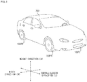
- FIG. 1 is a view illustrating the exterior of a vehicle provided with a display apparatus
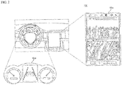
- FIG. 2 is a view illustrating the display apparatus for vehicles according to an embodiment of the present invention.
- a vehicle 700 includes wheels 103FR, 103FL, 103RL,... which are rotated by a power source and a steering input apparatus for adjusting the travel direction of the vehicle 700, and a display apparatus 100 provided in the vehicle 700.
- the overall length refers to the length of the vehicle 700 from the front to back of the vehicle
- the width refers to the width of the vehicle 700
- the height refers to the distance from the bottom of a wheel to the roof of the vehicle.
- the overall-length direction L indicates a direction in which measurement of the overall length of the vehicle 700 is performed
- the width direction W indicates a direction in which measurement of the width of the vehicle 700 is performed
- the height direction H indicates a direction in which measurement of the height of the vehicle 700 is performed.
- the display apparatus 100 may be positioned in one area of a cockpit module to allow a user to check a screen displayed on the display.
- a display apparatus 100a may be disposed in one area of the center fascia and a display apparatus 100b may be disposed around the steering wheel.
- the display apparatus 100 may also include a transparent display or a head up display (HUD) to display content on the windshield.
- HUD head up display
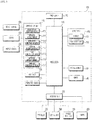
- FIG. 3 is a block diagram illustrating a display apparatus for vehicles according to an embodiment of the present invention.
- the display apparatus 100 includes a communication unit 110, an input unit 120, a temperature sensor 126, an interface unit 130, a memory 140, an output unit 150, a heating element 160, a processor 170, and a power supply 190.
- the communication unit 110 may include at least one module enabling wireless communication between the display apparatus 100 and a mobile terminal 600, between the display apparatus 100 and an external server 601 or between the display apparatus 100 and another vehicle 602.
- the communication unit 110 may also include at least one module for connecting the display apparatus 100 to at least one network.
- the communication unit 110 includes a broadcast reception module 111, a mobile communication module 112, a short-range communication module 113, a location information module 114, a V2X communication module 115, a wireless Internet module 116, and a smart key communication module 117.
- the broadcast reception module 111 receives a broadcast signal or broadcast-related information from an external broadcast management server over a broadcast channel. Further, the broadcast includes radio broadcast or TV broadcast.
- the mobile communication module 112 transmits and receives a radio signal to and from at least one of a base station, an external terminal and a server over a mobile communication network which is built according to the connected standards for mobile communication or communication schemes (e.g., GSM (Global System for Mobile communication), CDMA (Code Division Multi Access), CDMA2000 (Code Division Multi Access 2000), EV-DO (Enhanced Voice-Data Optimized or Enhanced Voice-Data Only), WCDMA (Wideband CDMA), HSDPA (High Speed Downlink Packet Access), HSUPA (High Speed Uplink Packet Access), LTE (Long Term Evolution), LTE-A (Long Term Evolution-Advanced), etc.).
- GSM Global System for Mobile communication
- CDMA Code Division Multi Access
- CDMA2000 Code Division Multi Access 2000
- EV-DO Enhanced Voice-Data Optimized or Enhanced Voice-Data Only
- WCDMA Wideband CDMA
- HSDPA High Speed Downlink Packet Access
- HSUPA High Speed Uplink Packet Access
- the radio signal may contain various kinds of data according to transmission and reception of a voice call signal, a video call signal, or a text/multimedia message.
- the short-range communication module 113 which is used for short-range communication, supports short-range communication using at least one of BluetoothTM, Radio Frequency Identification (RFID), Infrared Data Association (IrDA), ultra wideband (UWB), ZigBee, Near Field Communication (NFC), Wi-Fi, Wi-Fi Direct, and Wireless Universal Serial Bus (Wireless USB) technologies.
- RFID Radio Frequency Identification
- IrDA Infrared Data Association
- UWB ultra wideband
- ZigBee Near Field Communication
- Wi-Fi Wi-Fi Direct
- Wireless Universal Serial Bus Wireless Universal Serial Bus
- the short-range communication module 113 can establish a wireless local area network to implement short-range communication between the vehicle 700 and at least one external device.
- the short-range communication module 113 can wirelessly exchange data with the mobile terminal 600, and receive weather information and traffic situation information (e.g., TPEG (Transport Protocol Expert Group)) from the mobile terminal 600.
- TPEG Transport Protocol Expert Group
- the mobile terminal 600 of the user can be paired with the vehicle 700 automatically or by execution of an application by the user.
- An example of the location information module 114 which serves to acquire the location of the vehicle 700, is a global positioning system (GPS) module.
- GPS global positioning system
- the location of the vehicle can be acquired using a signal from a GPS satellite.
- the V2X communication module 115 serves to perform wireless communication with the server 601 or another vehicle 602.
- the V2X communication module 115 includes a module capable of implementing a vehicle-to-vehicle communication (V2V) protocol or a vehicle-to-infrastructure communication (V2I) protocol.
- the vehicle 700 can perform wireless communication with the external server 601 or the vehicle 602 through the V2X communication module 115.
- the wireless Internet module 116 which refers to a module for wireless Internet access, may be installed inside or outside the vehicle 700.
- the wireless Internet module 116 is also configured to transmit and receive a radio signal over a communication network according to wireless Internet technologies.
- wireless Internet technologies include Wireless LAN (WLAN), Wi-Fi, Wi-Fi Direct, Digital Living Network Alliance (DLNA), Wireless Broadband (WiBro), World Interoperability for Microwave Access (WiMAX), High Speed Downlink Packet Access (HSDPA), High Speed Uplink Packet Access (HSUPA), Long Term Evolution (LTE), and Long Term Evolution-Advanced (LTE-A).
- the wireless Internet module 116 transmits and receives data according to at least one of the aforementioned wireless Internet technologies.
- the wireless Internet module 116 can wirelessly exchange data with the external server 601 and receive weather information and traffic situation information (e.g., TPEG (Transport Protocol Expert Group)) from the external server 601.
- TPEG Transport Protocol Expert Group
- the smart key communication module 117 can perform wireless communication with a smart key carried by the user using low-frequency (LF) communication.
- the smart key communication module 117 can sense a distance between the vehicle 700 and the user based on the strength of a signal received from the smart key such as based on a Received Signal Strength Indication (RSSI).
- RSSI Received Signal Strength Indication
- the input unit 120 may include a user input unit and a sound input unit.
- the user input unit serves to receive information from the user and when information is input through the user input unit, the processor 170 can control operation of the display apparatus 100 to correspond to the input information.
- the user input unit may include a touch input or a mechanical input.
- the sound input unit can process an external sound signal to create and use electrical data for various purposes according to functions being executed by the display apparatus 100.
- the sound input unit can convert a voice command from the user into electrical data and then deliver the electrical data to the processor 170.
- the temperature sensor 126 can sense temperature by employing one of thermal expansion, thermal electromotive force, electric resistance, a semiconductor, a magnetic element, elasticity, radiation, and a photoelectric effect.
- the temperature sensor 126 may include an NTC thermistor, and sense the temperature using the property of the thermistor whose resistance varies with temperature.
- the temperature sensor 126 can also sense the temperature of the interior of the vehicle 700.
- the temperature sensor 126 can sense the temperature of the surroundings of the display 151 or the temperature of the interior of the vehicle 700 and also sense the temperature of a liquid crystal panel 311 (see FIG. 7 ).
- the interface unit 130 can receive data, information and signals, or transmit data, information and signals processed or generated by the processor 170.
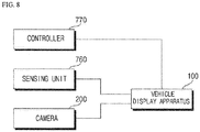
- the interface unit 130 can perform data communication with a controller 770, a sensing unit 760, a vehicle drive unit 750, a camera 200, and the like, which are included in the vehicle, through wired or wireless communication.
- the interface unit 130 can also receive sensor information from the controller 770 or the sensing unit 760.
- the sensor information includes vehicle direction information, vehicle location information (GPS information), vehicle orientation information, vehicle speed information, vehicle acceleration information, vehicle inclination information, vehicle drive/reverse information, battery information, fuel information, tire information, vehicle lamp information, vehicle interior temperature information, vehicle exterior temperature information, vehicle interior humidity information and/or vehicle exterior illumination information, for example.
- GPS information vehicle location information
- vehicle orientation information vehicle speed information
- vehicle acceleration information vehicle acceleration information
- vehicle inclination information vehicle drive/reverse information
- battery information fuel information
- tire information tire information
- vehicle lamp information vehicle interior temperature information
- vehicle exterior temperature information vehicle interior humidity information
- vehicle exterior illumination information for example.
- the sensing unit 760 senses a signal related to traveling of the vehicle 700.
- the sensor information can be received from a heading sensor, a yaw sensor, a gyro sensor, a position module, a vehicle drive/reverse drive sensor, a wheel sensor, a vehicle speed sensor, a vehicle body tilt sensor, a battery sensor, a fuel sensor, a tire sensor, a steering sensor based on turning of the steering wheel, a vehicle interior temperature sensor, a vehicle exterior temperature sensor, a vehicle interior humidity sensor, an illumination sensor, and the like.
- the position module may also include a GPS module for receiving GPS information.
- vehicle travel information Of the sensor information, vehicle direction information, vehicle location information, vehicle orientation information, vehicle speed information and vehicle inclination information which are related to travel of the vehicle is referred to as vehicle travel information.
- vehicle travel information Of the sensor information, vehicle direction information, vehicle location information, vehicle orientation information, vehicle speed information and vehicle inclination information which are related to travel of the vehicle is referred to as vehicle travel information.
- the interface unit 130 can also receive object information from the camera 200.
- the camera 200 can detect lane detection (LD), vehicle detection (VD), pedestrian detection (PD), bright-spot detection (BD), traffic sign recognition (TSR), and road surface detection, and the like based on an acquired image.
- the camera 200 can also generate information about the distance to a detected object.
- the interface unit 130 can receive surroundings-of-vehicle information from a communication unit 710 (see FIG. 5 ), the sensing unit 760 or the camera 200.
- the surroundings-of-vehicle information includes object information, weather information, driving road information, travel time information, illumination information and the like. Further, the object information includes information indicating presence or absence of an object, location information about the object, information about distance to the object and relative speed information about the object, for example.
- the interface unit 130 can receive remote engine start event information.
- the controller 770 of the vehicle 700 can start the engine of the vehicle 700.
- the interface unit 130 can receive engine on information from the controller 770.
- the interface unit 130 can receive user approach event information. Also, the object sensor 761 or the camera 200 of the vehicle 700 can sense an approach of the user. The interface unit 130 can also receive user approach event information from the object sensor 761 or the camera 200.
- the interface unit 130 can receive information about the distance to the user or approach speed information of the user.
- the object sensor 761 or the camera 200 of the vehicle 700 can calculate the distance to the user and the approach speed of the user. Further, the interface unit 130 can receive the information about the distance to the user or the user approach speed information from the object sensor 761 or the camera 200.
- the interface unit 130 can also receive door opening event information and the processor 170 can receive the door opening event information from the controller 770.
- the memory 140 is electrically connected to the processor 170 and can store basic data for each unit, control data for controlling operation of each unit, and input/output data.
- the memory 140 may correspond to various storage devices such as a ROM, RAM, EPROM, flash drive, and hard drive in terms of hardware.
- the memory 140 can also store various kinds of data for overall operation of the display apparatus 100 including a program for processing or controlling the processor 170.
- the memory 140 may also store map data for implementing the navigation function. Further, the map data can be stored as a default when the vehicle is shipped. Alternatively, the map data can be received from an external device through the communication unit 110 or the interface unit 130. According to an embodiment, the memory 140 may be integrated with the processor 170.
- the output unit 150 which serves to output information processed by the processor 170, includes a display unit 151 and a sound output unit 152.
- the display 151 displays information processed by the processor 170.
- the display 151 may display vehicle-related information.
- vehicle-related information includes vehicle control information for direct control of the vehicle or vehicle driving assistance information for assisting the driver in driving the vehicle.
- vehicle-related information may also include vehicle condition information indicating the current condition of the vehicle or vehicle driving information related to driving of the vehicle.
- the display 151 may include at least one of a liquid crystal display (LCD), a thin film transistor-liquid crystal display (TFT LCD), an organic light-emitting diode (OLED) display, a flexible display, a 3D display and an e-ink display.
- LCD liquid crystal display
- TFT LCD thin film transistor-liquid crystal display
- OLED organic light-emitting diode
- the display 151 may form a layered structure together with a touch sensor or be integrated with the touch sensor, thereby implementing a touchscreen.
- the touchscreen functions as a user input unit providing an input interface between the display apparatus 100 and the user and an output interface between the display apparatus 100 and the user.
- the display 151 may include a touch sensor for sensing a touch applied to the display 151 in order to receive a control command in a touch manner.
- the display 151 can receive a touch input.
- the touch sensor can sense the touch, and the processor 170 can generate a control command corresponding to the touch.
- Content input through touch may include characters, numbers, or menu items which can be indicated or specified in various modes.
- the display 151 may be implemented to display a screen is in one area of the windshield and may include a transparent display.
- the transparent display may be attached to the windshield and output information.
- the transparent display may also have predetermined transparency and display a predetermined screen image.
- the transparent display may include at least one of a transparent thin film electroluminescent (TFEL) display, a transparent organic light-emitting diode (OLED), a transparent liquid crystal display (LCD), a light-transmittable transparent display and a transparent light emitting diode display (LED).
- TFEL transparent thin film electroluminescent
- OLED transparent organic light-emitting diode
- LCD transparent liquid crystal display
- LED transparent light emitting diode display
- the transparency of the transparent display can also be adjusted according to control of the processor 170.
- the display 151 may include a projection module and output information through an image projected onto the windshield.
- the projection module protects a beam toward the windshield or a screen provided in the vehicle using a light source and a projection lens.
- the projection module can also implement an image corresponding to the information processed by the processor 170. That is, the projection module can implement an image using light generated from the light source, and project the implemented image onto the windshield. In this instance, LEDs, lasers, or the like are preferably used as the light source.
- the sound output unit 152 converts an electrical signal from the processor 170 into an audio signal and outputs the audio signal.
- the sound output unit 152 may also be provided with a speaker and output sound corresponding to operation of the user input unit.
- the heating element 160 provides heat to the display 151 and may be formed in the shape of a film. In this instance, the heating element 160 may be referred to as a heating film. The heating element 160 will be described with reference to FIGS. 6 and 7 later.
- the processor 170 is electrically connected to the respective units in the display apparatus 100. Thereby, the processor 170 controls overall operation of the respective units.
- the processor 170 also controls the output unit 150 to output the information or data received through the communication unit 110, the input unit 120 or the interface unit 130.
- the processor 170 controls the output unit 150 to output information or data stored in the memory 140.
- the processor 170 can directly output received information or data or process and output the information or data and output the information or data through the display 151.
- the processor 170 can also audibly output the information or data through the sound output unit 152.
- the processor 170 can generate new information based on the information or data received through the interface unit 130 and control the display 151 to display the generated information or a screen image corresponding to the generated information.
- the processor 170 can also acquire interior temperature information or exterior temperature information about the vehicle 700.
- the processor 170 can control the heating element 160 to produce heat based on the interior temperature information or the exterior temperature information.
- the heating element 160 can provide heat to the display to allow the display 151 to normally operate even in a low-temperature environment.
- the processor 170 can control the heating element 160 to produce heat based on the temperature of the surroundings of the display 151 sensed by the temperature sensor 126.
- the processor 170 can control the heating element 160 to produce heat based on the temperature information about the liquid crystal panel 311 (see FIG. 7 ) sensed by the temperature sensor 126.
- the exterior temperature information may be provided to the external server 601 through the communication unit 110.
- the processor 170 can receive temperature information corresponding to the location of the vehicle 700 from the weather information providing server 601, based on the location information about the vehicle 700 acquired through the location information module 114.
- the processor 170 can also receive event information through the interface unit 130. Further, the image information may be event information for controlling the heating element 160. Upon receiving the event information, the processor 170 can control the heating element 160 to produce heat. The event information may also be received through the communication unit 110, and received from the camera 200 or the sensing unit 760 of the vehicle 700.
- the processor 170 can receive remote engine start event information through the interface unit 130.
- the controller 770 of the vehicle 700 may start the engine of the vehicle 700.
- the processor 170 can receive engine on information from the controller 770 through the interface unit 130.
- the processor 170 can receive remote engine start event information through the communication unit 170.
- the processor 170 can receive start event information through the smart key communication module 117.
- the processor 170 can control the heating element 160 to produce heat according to the remote engine start event information.
- the display 151 can normally operate in a cold environment before the user enters the vehicle 700.
- the processor 170 can acquire user approach event information through the interface unit 130.
- the processor 170 can receive user information from the sensing unit 760 or the camera 200 through the interface unit 130.
- the user information may include information about the distance to the user, and approach speed information about the user. If the distance to the user is within a predetermined distance, the processor can determine that the user approaches and acquire the user approach event information. Alternatively, the processor 170 can receive user approach event information through the communication unit 170. For example, the processor 170 can receive the user approach event information through the smart key communication module 117.
- the processor 170 can control the heating element 160 to produce heat according to the user approach event information.
- the display 151 can normally operate in a cold environment before the user enters the vehicle 700.
- the processor 170 can also control the degree of heating of the heating element 160 according to the approach speed of the user. Further, the degree of heating includes a heating rate or the amount of produced heat. For example, the processor 170 can control the heating rate or the amount of produced heat of the heating element 160 to increase in proportion to the approach speed of the user.
- user approach speed information can be received through the interface unit 130 or acquired through the communication unit 110.
- the display can normally operate even when the user rapidly approaches the vehicle.
- the processor 170 can receive door opening event information about the vehicle 700 through the interface unit 130 and control the heating element to produce heat according to the door opening event information. Upon receiving the door opening event, the processor 170 can control the heating element 160 to produce maximum heat. For example, when the door opening event is received, the processor 170 can control the heating element 160 to produce heat at a maximum rate such as at a maximum heating rate.
- the processor 170 can provide an air conditioner included in the vehicle 700 with a control signal for supplying warm air to the display 151.
- the processor 170 can provide the control signal to the air conditioning drive unit 755 of the vehicle 700 and the air conditioning drive unit 755 of the vehicle 700 can control the air conditioner to supply warm air to the display 151. In this instance, it is preferable to provide warm air with a maximum power at a maximum temperature.
- the temperature of the display 151 can be increased to a temperature allowing normal operation of the display 151 in a short time.
- the processor 170 can receive a reservation time input through a touch input to the display 151, for example and can control the heating element 160 to produce heat at the reservation time.
- the processor 170 can receive a heating duration input through touch input to the display 151, for example and control the heating element 160 to produce heat for the heating duration. After the heating duration passes, the processor 170 can control the heating element 160 to stop producing heat.
- the processor 170 can control the heating element 160 to stop producing heat if the vehicle 700 fails to start even after a preset time passes.
- the display 151 can properly operate as desired by the user.
- the processor 170 can receive information about the temperature of the surroundings of the display 151 from the temperature sensor 126 and control the heating element 160 to maintain the temperature of the surroundings of the display 151 within a predetermined range.
- the processor 170 can control the heating element 160 to maintain the temperature of the liquid crystal panel 311 (see FIG. 7 ) within a predetermined range.
- the predetermined range may be a temperature range allowing the display 151 to operate normally.
- the processor 170 can control the heating element 160 to stop producing heat.
- the heating element 160 By controlling the heating element 160 according to the temperature of the surroundings of the display in this manner, an optimum temperature for operation of the display 151 is provided to allow the display 151 to operate normally.
- the processor 170 can control the degree of heating of the heating element 160 in proportion to the absolute value of the interior temperature of the vehicle 700 or the exterior temperature of the vehicle 700. Further, the degree of heating includes a heating rate or the amount of produced heat. For example, the processor 170 can control the rate of heating or the amount of produced heat of the heating element 160 to increase in proportion to the absolute value.
- the processor 170 can acquire location information about the vehicle 700 through the location information module 114 and can control the degree of heating of the heating element 160 based on the location information. Further, the degree of heating includes a heating rate or the amount of produced heat. For example, the processor 170 can receive temperature information corresponding to the location of the vehicle 700 from the weather information providing server 601, based on the location information about the vehicle 700 acquired through the location information module 114 and control the degree of heating of the heating element 160 based on the temperature information.
- the processor 170 can provide a control signal for supplying warm air to the display 151 to an air conditioner included in the vehicle 700.
- the heating element 160 may be uncontrollable due to failure of the heating element 160.
- the processor 170 can provide a control signal to the air conditioning drive unit 755, and air conditioning drive unit 755 can control the air conditioner according to the control signal.
- the air conditioner can then provide warm air into the vehicle to supply warm air to the display 151.
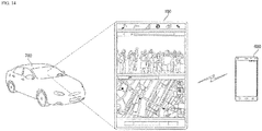
- the processor 170 can also provide interior temperature information or exterior temperature information about the vehicle 700 to an external device through the communication unit 110. Further, the external device may be a mobile terminal 600 carried by the user.
- the processor 170 can receive a control signal for controlling the heating element 160 to produce heat from an external device such as the mobile terminal 600 through the communication unit 110. The processor 170 can then control the heating element 160 according to the received control signal.
- the processor 170 can also provide information indicating whether the heating element 160 produces heat to an external device such as the mobile terminal 600 through the communication unit 110.
- the processor 470 may be implemented using at least one of application specific integrated circuits (ASICs), digital signal processors (DSPs), digital signal processing devices (DSPDs), programmable logic devices (PLDs), field programmable gate arrays (FPGAs), processors, controllers, micro-controllers, microprocessors, and electric units for performing other functions.
- the power supply 190 can be controlled by the processor 170 to supply electric power for operation of respective constituents.
- the power supply 190 can receive power from, for example, a battery in the vehicle.
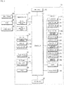
- FIG. 4 is a flowchart illustrating operation of a display apparatus for vehicles according to an embodiment of the present invention.
- the processor 170 acquires temperature information (S410). Further, the temperature information may include an interior temperature of the vehicle 700 or an exterior temperature of the vehicle 700.
- the processor 170 can receive information about the interior temperature or exterior temperature of the vehicle 700 from the sensing unit 760 through the interface unit 130, receive information about the interior temperature of the vehicle 700 through the temperature sensor 126, and receive temperature information corresponding to the location information about the vehicle 700 from the weather information providing server 601 through the communication unit 110.
- the processor 170 acquires event information (S420), which may be trigger data for controlling the heating element 160 to produce heat.
- event information S420
- the processor 170 can acquire remote engine start event information, user approach event information and door opening event information.
- the processor 170 controls the heating element to produce heat based on the temperature information or the event information (S430). For example, the processor 170 can control the heating element 160 to produce heat based on the interior temperature information or the exterior temperature information. For example, when the processor 170 receives event information, the processor 170 can control the heating element 160 to produce heat.
- the processor 170 can provide a control signal to the air conditioning drive unit 755 configured to drive the air conditioner in order to provide warm air to the display 151 (S440).
- Step S440 is selectively operable according to an embodiment of the present invention. For example, upon receiving the door open event information, the processor 170 can provide the air conditioner included in the vehicle 700 with a control signal for supplying warm air to the display 151.
- the processor 170 can provide the control signal to the air conditioning drive unit 755 of the vehicle 700 to control the air conditioner to supply warm air to the display 151. In this instance, it is preferable to provide warm air with maximum power at maximum temperature.
- the temperature of the display 151 can be increased to a temperature allowing normal operation of the display 151 in a short time. If the heating element 160 is not controllable, the processor 170 can provide a control signal for supplying warm air to the display 151 to an air conditioner included in the vehicle 700.
- the heating element 160 may be uncontrollable due to failure of the heating element 160.
- the processor 170 can provide a control signal to the air conditioning drive unit 755 to control the air conditioner according to the control signal.
- the air conditioner can also provide warm air into the vehicle to supply warm air to the display 151. Thereby, even if the heating element 160 fails, the display 150 can normally operate as warm air is provided to the display 151 by controlling the air conditioner.
- FIG. 5 is a block diagram illustrating a vehicle according to an embodiment of the present invention.
- the vehicle 700 includes a communication unit 710, an input unit 720, a sensing unit 760, an output unit 740, a vehicle drive unit 750, a memory 730, an interface unit 780, a controller 770, a power supply 790, a camera 200 and a display apparatus 100 for the vehicle.
- the communication unit 710 includes at least one module enabling wireless communication between the vehicle 700 and a mobile terminal 600, between the vehicle 700 and an external server 601, or between the vehicle 700 and another vehicle 602.
- the communication unit 710 may also include at least one module for connecting the vehicle 700 to at least one network.
- the communication unit 710 may include an optical communication module 715 and a V2X communication module 716.
- the optical communication module 715 may include a light transmitter and a light receiver.
- the light receiver can covert a light signal into an electrical signal to receive information
- the light receiver can include a photodiode (PD) for receiving light.
- the PD converts light into an electrical signal.
- the light receiver can receive information on a preceding vehicle through light emitted from a light source included in the preceding vehicle.
- the light transmitter may include at least one light emitting device for converting an electrical signal into a light signal.
- the light emitting device is a light emitting diode (LED).
- the light transmitter converts an electrical signal into a light signal and transmits the light signal outside. For example, the light transmitter transmits a light signal by blinking a light emitting device at a predetermined frequency.
- the light transmitter includes an array of a plurality of light emitting devices. Further, the light transmitter may be integrated with a lamp provided to the vehicle 700.
- the light transmitter may be a headlight, a taillight, a stop lamp, a turn signal lamp and a sidelight.
- the optical communication module 715 can exchange data with the vehicle 602 through optical communication.
- the input unit 720 includes a driving manipulation apparatus 721, a microphone 723 and a user input unit 724.
- the driving manipulation apparatus 721 receives user input for driving the vehicle 700 and may include a steering input apparatus, a shift input apparatus, an acceleration input apparatus, and a brake input apparatus.
- the steering input apparatus receives a travel direction input of the vehicle 700 from the user.
- the steering input apparatus is formed in the shape of a wheel to allow steering input through rotation.
- the steering input apparatus may include a touchscreen, a touch pad, or a button.
- the shift input apparatus receives, from the user, inputs for Park (P), Drive (D), Neutral (N) and Reverse (R) of the vehicle 700.
- the shift input apparatus is formed in the shape of a lever.
- the shift input apparatus may include a touchscreen, a touch pad, or a button.
- the acceleration input apparatus receives an input for accelerating the vehicle 700 from the user, and brake input apparatus receives an input for decelerating the vehicle 700 from the user.
- the acceleration input apparatus and the brake input apparatus are formed in the shape of a pedal.
- the acceleration input apparatus and the brake input apparatus may include a touchscreen, a touch pad, or a button.
- the microphone 723 processes an external sound signal to create electrical data that can be utilized for various purposes according to functions being executed by the vehicle 700.
- the microphone 723 can also convert a voice command from the user into electrical data to be delivered to the controller 770.
- the camera 722 or the microphone 723 may be a constituent included in the sensing unit 760 rather than being included in the input unit 720.
- the user input unit 724 is intended to receive information from the user. When information is input through the user input unit 724, the controller 770 can control operation of the vehicle 700 in accordance with the input information.
- the user input unit 724 may also include a touch input mechanism or a mechanical input mechanism. According to some embodiments, the user input unit 724 may be disposed in one area of the steering wheel. In this instance, the driver can manipulate the user input unit 724 with their fingers while holding the steering wheel.
- the sensing unit 760 senses a signal related to traveling of the vehicle 700.
- the sensing unit 760 may include a collision sensor, a wheel sensor, a speed sensor, a tilt sensor, a weight sensor, a heading sensor, a yaw sensor, a gyro sensor, a position module, a vehicle drive/reverse drive sensor, a battery sensor, a fuel sensor, a tire sensor, a steering sensor based on turning of the steering wheel, a vehicle interior temperature sensor, a vehicle exterior temperature sensor, a vehicle interior humidity sensor, and a rain sensor.
- the sensing unit 760 can acquire sensing signals carrying vehicle collision information, vehicle direction information, vehicle location information (GPS information), vehicle orientation information, vehicle speed information, vehicle acceleration information, vehicle inclination information, vehicle drive/reverse information, battery information, fuel information, tire information, vehicle lamp information, vehicle interior temperature information, vehicle exterior temperature information, vehicle interior humidity information, information about whether it rains, and an angle by which the steering wheel is rotated.
- GPS information vehicle location information
- vehicle orientation information vehicle speed information
- vehicle acceleration information vehicle acceleration information
- vehicle inclination information vehicle drive/reverse information
- battery information fuel information, tire information, vehicle lamp information, vehicle interior temperature information, vehicle exterior temperature information, vehicle interior humidity information, information about whether it rains, and an angle by which the steering wheel is rotated.
- the sensing unit 760 may further include an accelerator pedal sensor, a pressure sensor, an engine speed sensor, an air flow sensor (AFS), an intake air temperature sensor (ATS), a water temperature sensor (WTS), a throttle position sensor (TPS), a TDC sensor, and a crankshaft angle sensor (CAS).
- the sensing unit 760 may also include a biometric identification information sensing unit that senses and acquires biometric identification information of a passenger.
- the biometric identification information may include fingerprint information, iris scan information, retina scan information, hand geometry information, facial recognition information, and voice recognition information.
- the biometric identification information sensing unit may also include a sensor for sensing biometric identification information of a person in the vehicle. Further, the interior camera and the microphone 723 may operate as sensors. The biometric recognition information sensing unit can also acquire hand shape information and face recognition information through the interior camera.
- the sensing unit 760 may include an object sensor 761 including one of a radar, a lidar, an ultrasonic sensor, a TOF sensor and an infrared sensor.
- the object sensor 761 includes a radar or a lidar. If the object sensor 761 is provided with a radar or a lidar, the object sensor 761 can sense presence of an object, a distance to the object, a relative speed of the object, and the location of the object.
- data, a signal or information generated by the object sensor 761 is transmitted to the controller 770, and the object sensor 761 can sense an object located around the vehicle 700 such as a user.
- the object sensor 761 can also calculate the distance to the object and calculate an approach speed of the object based on the distance information.
- the output unit 740 which serves to output information processed by the controller 770, may include a display unit 741, a sound output unit 742 and a haptic output unit 743.
- the display unit 741 can display information processed by the controller 770 such as displaying vehicle-related information.
- vehicle-related information may include vehicle control information for controlling the direction of the vehicle or vehicle driving assistance information for assisting the driver in driving the vehicle.
- vehicle-related information may also include vehicle condition information indicating the current condition of the vehicle or vehicle driving information related to driving.
- the display unit 741 may include one of a liquid crystal display (LCD), a thin film transistor-liquid crystal display (TFT LCD), an organic light-emitting diode (OLED) display, a flexible display, a 3D display and an e-ink display.
- LCD liquid crystal display
- TFT LCD thin film transistor-liquid crystal display
- OLED organic light-emitting diode
- the display unit 741 may also form a layered architecture together with a touch sensor or be integrated with the touch sensor, thereby implementing a touchscreen.
- Such touchscreen can thus function as the user input unit 724 providing an input interface between the vehicle 700 and the user and also as an output interface between the vehicle 700 and the user.
- the display unit 741 may include a touch sensor for sensing touch applied to the display unit 741 in order to receive a control command in a touch manner. Thereby, when the display unit 741 is touched, the touch sensor can sense the touch, and the controller 770 can generate a control command corresponding to the touch.
- Content input through touch includes characters, numbers, or menu items which can be indicated or specified in various modes.
- the display unit 741 may include a cluster to allow the driver to check the vehicle condition information or vehicle driving information during driving.
- the cluster may be positioned on the dashboard and the driver can check the information displayed on the cluster while looking forward.
- the display unit 741 may be implemented as a head up display (HUD). If the display unit 741 is implemented as the HUD, information can be output through a transparent display provided to the windshield. Alternatively, the display unit 741 may be provided with a projection module, thereby outputting information through an image projected onto the windshield.
- HUD head up display
- the sound output unit 742 converts an electrical signal from the controller 770 into an audio signal and outputs the audio signal.
- the sound output unit 742 may include a speaker, to output sound corresponding to operation of the user input unit 724.
- the haptic output unit 743 generates haptic output such as vibrating the steering wheel, a seat belt and a seat to allow the user to recognize the output.
- the vehicle drive unit 750 can also control operations of various vehicular devices and receive a control signal from the display apparatus 100 for vehicles. The vehicle drive unit 750 can control various devices based on the control signal.
- the vehicle drive unit 750 may include a power source drive unit 751, a steering drive unit 752, a brake drive unit 753, a lamp drive unit 754, an air conditioning drive unit 755, a window drive unit 756, an airbag drive unit 757, a sunroof drive unit 758 and a suspension drive unit 759.
- the power source drive unit 751 can perform electronic control of the power source in the vehicle 700.
- the power source drive unit 751 can perform electronic control of the engine. Thereby, the output torque of the engine can be controlled. If the power source drive unit 751 is an engine, the output torque of the engine can be controlled by the controller 770 to limit the speed of the vehicle. As another example, if an electric motor is the power source, the power source drive unit 751 can control the motor. Thereby, the rotational speed and torque of the motor can be controlled.
- the power source drive unit 751 can receive an acceleration control signal from the display apparatus 100 and control the power source according to the received acceleration control signal.
- the steering drive unit 752 can perform electronic control of the steering apparatus in the vehicle 700. Thereby, the steering drive unit 752 can change the travel direction of the vehicle.
- the steering drive unit 752 can receive a steering control signal from the display apparatus 100.
- the steering drive unit 752 can control the steering apparatus to be steered according to the steering control signal.
- the brake drive unit 753 can perform electronic control of a brake apparatus in the vehicle 700. For example, by controlling the operation of the brakes disposed on the wheels, the speed of the vehicle 700 can be reduced. In another example, the brake disposed on a left wheel can be operated differently from the brake disposed on a right wheel in order to adjust the travel direction of the vehicle 700 to the left or right.
- the brake drive unit 753 can also receive a deceleration control signal from the display apparatus 100. Further, the brake drive unit 753 can control the brake apparatus according to the received deceleration control signal.
- the lamp drive unit 754 can control lamps disposed inside and outside the vehicle to be turned on/off. In addition, the lamp drive unit 754 can control the intensity and direction of light from the lamps. For example, the lamp drive unit 754 can control a turn signal lamp and a brake lamp.
- the air conditioning drive unit 755 can perform electronic control of an air conditioner in the vehicle 700. For example, if the temperature of the interior of the vehicle is high, the air conditioning drive unit 755 can control the air conditioner to supply cool air to the interior of the vehicle.
- the window drive unit 756 can perform electronic control of a window apparatus in the vehicle 700.
- the window drive unit 756 can control opening or closing of the left and right windows on both sides of the vehicle.
- the airbag drive unit 757 can perform electronic control of an airbag apparatus in the vehicle 700.
- the airbag drive unit 757 can control the airbag apparatus such that the airbags are inflated when the vehicle is exposed to danger.
- the sunroof drive unit 758 can perform electronic control of a sunroof apparatus in the vehicle 700.
- the sunroof drive unit 758 can control opening or closing of the sunroof.
- the suspension drive unit 759 can perform electronic control of a suspension apparatus in the vehicle 700.
- the suspension drive unit 759 can control the suspension apparatus to attenuate vibration of the vehicle 700.
- the suspension drive unit 759 can also receive a suspension control signal from the display apparatus 100 and control the suspension apparatus according to the received suspension control signal.
- the memory 730 is electrically connected to the controller 770 and can store basic data for each unit, control data for controlling operation of each unit, and input/output data.
- the memory 730 may include various storage devices such as a ROM, RAM, EPROM, flash drive, and hard drive.
- the memory 730 can also store various kinds of data for overall operation of the vehicle 700 including a program for processing or controlling operation of the controller 770.
- the interface unit 780 serves as a path between the vehicle 700 and various kinds of external devices connected thereto.
- the interface unit 780 may be provided with a port connectable to the mobile terminal 600, thus being connected to the mobile terminal 600 through the port.
- the interface unit 780 can exchange data with the mobile terminal 600.
- the interface unit 780 also serves as a path through which electrical energy is supplied to the mobile terminal 600 connected thereto. If the mobile terminal 600 is electrically connected to the interface unit 780, the interface unit 780 is controlled by the controller 770 to provide the mobile terminal 600 with electrical energy supplied from the power supply 790.
- controller 770 can control overall operations of the respective units in the vehicle 700 and be called an electronic control unit (ECU).
- the controller 770 may be implemented as hardware using at least one of application specific integrated circuits (ASICs), digital signal processors (DSPs), digital signal processing devices (DSPDs), programmable logic devices (PLDs), field programmable gate arrays (FPGAs), processors, controllers, micro-controllers, microprocessors, and electric units for performing other functions.
- ASICs application specific integrated circuits
- DSPs digital signal processors
- DSPDs digital signal processing devices
- PLDs programmable logic devices
- FPGAs field programmable gate arrays
- processors controllers, micro-controllers, microprocessors, and electric units for performing other functions.
- the power supply 790 can be controlled by the controller 770 to supply electric power necessary for operation of respective constituents.
- the power supply 790 may be supplied with power from, for example, a battery in the vehicle.
- the camera 200 can acquire a surroundings-of-vehicle image and may include at least one lens and at least one image sensor (e.g., CMOS or CCD), and an image processor.
- the camera 200 can detect an object from the surroundings-of-vehicle image. In detecting objects, the camera 200 can perform lane detection (LD), vehicle detection (VD), pedestrian detection (PD), bright-spot detection (BD), traffic sign recognition (TSR), and road surface detection, structure detection, and the like.
- LD lane detection
- VD vehicle detection
- PD pedestrian detection
- BD bright-spot detection
- TSR traffic sign recognition
- road surface detection structure detection, and the like.
- the camera 200 can also verify the detected object using a verification technique such as neural network, support vector machine (SVM), AdaBoost using Haar-like features, and histograms of oriented gradients (HOG).
- a verification technique such as neural network, support vector machine (SVM), AdaBoost using Haar-like features, and histograms of oriented gradients (HOG).
- the camera 200 can perform the verification operation by comparing the detected object in the surroundings-of-vehicle image with data stored in the memory 140.
- the camera 200 can track the verified object, calculate motion of the verified object or motion vectors of the verified object, and track movement of the object based on the calculated motion or motion vectors.
- the camera 200 can also generate information about the distance to the object based on the surroundings-of-vehicle image and acquire information about the distance between the vehicle 700 and the object based on disparity information.
- the camera 200 can generate disparity information based on a stereo image, and acquire the distance information about the object based on the generated disparity information.
- the stereo image may be an image acquired through a stereo camera.
- the camera 200 can generate disparity information based on a plurality of mono images, and acquire the distance information about the object based on the generated disparity information.
- the plurality of mono image may be acquired through one camera at predetermined time intervals, and the mono image may be acquired through a mono camera or an around view camera.
- the camera 200 can generate relative speed information about an object by tracking the object and calculate the relative speed information about the object based on variation of the distance to the object with time with the information about the distance to the object acquired.
- the camera 200 may include a mono camera, a stereo camera and an around view camera.
- the mono camera may include one lens, and one image sensor, and acquire mono images
- the stereo camera may include two lenses and two image sensors, and acquire stereo images
- the around view camera may include four lenses and four image sensors, and acquire around view images.
- the around view camera may be a camera employed by an around view monitoring (AVM) system.
- AVM around view monitoring
- the camera 200 can detect a user. For example, the camera 200 can detect the user by detecting feature points of the face of the user. The camera 200 can also calculate the distance to the user. In this instance, the camera 200 can use the aforementioned method of detecting the distance to an object. The camera 200 can also calculate the approach speed of the user based on the distance information.
- the display apparatus 100 can exchange data with the controller 770, and the controller 770 can receive navigation information from the display apparatus 100 or a separate navigation apparatus.
- the navigation information may include designated destination information, route information according to the destination, map information, or location information about the vehicle, where the map information and location information are related to traveling of the vehicle.
- FIG. 6 is a view schematically illustrating a heating element 330 according to an embodiment of the present invention.
- the heating element 330 includes bus bars 332 and 333 and a conductive heating mechanism 331 electrically connected to the bus bars 332 and 333.
- the conductive heating mechanism 331 refers to a mechanism which is electrically connected to the bus bars 332 and 333 and is capable of producing heat according to the resistance and thermal conductivity thereof when a voltage is applied to the bus bars 332 and 333.
- a conductive material having the shape of a plane or a line may be used as the heating mechanism 331.
- the heating mechanism 331 When the heating mechanism 331 has a planar shape, the heating mechanism 331 may be formed of a transparent conductive material such as, for example, ITO and ZnO or of a thin film of an opaque conductive material. When the heating mechanism 331 has a line shape, the heating mechanism 331 may be formed of a transparent or opaque conductive material. According to an embodiment of the present invention, when the heating mechanism 331 has a line shape, the heating mechanism 331 may be configured not to obstruct the view of the user by adjusting the line width and the uniformity of a pattern even if the heating mechanism is formed of an opaque material such as a metal.
- the heating element 330 may include a heating line.
- the heating element may include a plurality of irregular patterns formed by irregular thickness lines.
- the heating mechanism 331 may be referred to as a conductive heating surface if the heating mechanism has a planar shape. Also, if the heating mechanism 331 has a line shape, the heating mechanism 331 may be referred to as a conductive heating line. When heat is produced using a heating element, an increment of temperature is determined by power per unit area.
- a conductive heating line may be a straight line or may have other forms such as a curve, a wavy line and a zigzag line.
- the conductive heating line may be formed in a pattern such as stripe, diamond, square lattice, circle, wave, grid and two-dimensional grid.
- the conductive heating line is not limited to specific shapes, but is preferably designed not to deteriorate the optical properties of light emitted from a certain light source due to diffraction and interference of light. That is, to minimize regularity of a pattern, a pattern provided with irregular spacing and line thickness of a wavy pattern, a sine wave and a lattice structure may be used.
- the pattern of the conductive heating line may also be a combination of two or more patterns.
- the conductive heating line may include an irregular pattern in which the ratio of the standard deviation to the average of distances of adjacent intersection points of the conductive heating line to a straight line intersecting the conductive heating line (distance distribution ratio) is greater than or equal to 2%, for example.
- the line intersecting the conductive heating line may also be a line providing the smallest standard deviation of distances of the line to adjacent intersection points of the conductive heating line.
- the line intersecting the conductive heating line may be a line perpendicular to a tangential line at a point on the conductive heating line.
- the straight line intersecting the conductive heating line may have at least 80 intersection points.
- the ratio of the standard deviation to the average of distances of adjacent intersection points of the conductive heating line to the straight line intersecting the conductive heating line may be greater than or equal to 2%, 10% or 20%.
- At least one portion of the surface of a transparent substrate provided with the heating line pattern described above may have another conductive heating line pattern.
- the irregular pattern may include closed geometric figures exhibiting continuous distribution, and include a pattern having a ratio of the standard deviation to the average of the areas of the closed geometric figures (area distribution ratio) greater than or equal to 2%.
- the number of the closed geometric figures may be greater than or equal to 100.
- the ratio of the standard deviation to the average of the areas of the closed geometric figures may be greater than or equal to 2%, 10% or 20%.
- At least one portion of the surface of a transparent substrate provided with the aforementioned heating line pattern with a ratio of the standard deviation to the average of the areas of the closed geometric figures (area distribution ratio) is greater than or equal to 2% may have another conductive heating line pattern.
- the present invention can properly harmonize regularity and irregularity in forming a heating line.
- a basic unit may be defined so as not to make the heating line noticeable or to cause local heating, and the heating line may be formed in a an irregular pattern within the basic unit. With this method, the line can be distributed not to be concentrated at one point, and thus the issue related to visibility can be addressed.
- the irregular pattern can include a conductive heating line pattern having the shape of a boundary line of geometric figures that forms a Voronoi diagram. Further, the irregular pattern may include a conductive heating line pattern having the shape of a boundary line of geometric figures including at least one triangle that forms a Delaunay pattern.
- the aperture ratio of the conductive heating line pattern per unit area may be set to be constant.
- the heating element may also have deviation of transmission factor less than or equal to 5% with respect to any circle having a diameter of 20 cm. In this instance, the heating element can prevent local heating.
- the standard deviation of temperatures on the surface of the transparent substrate may be within 20%.
- the conductive heating line may be disposed such that the heating element has a temperature deviation.
- the heating element 330 can be arranged on a transparent substrate.
- the transparent substrate is not specifically limited, but may have light transmittance greater than or equal to 50% or 75%.
- glass, a plastic substrate or a plastic film may be used as the transparent substrate.
- glass may be bonded to at least one surface of the substrate after a conductive heating line pattern is formed.
- glass or a plastic substrate may be bonded to a surface of the transparent substrate on which the conductive heating line pattern has been formed.
- the plastic substrate or film may be formed of a material well known in the art.
- the film may be formed of a material having visible light transmittance greater than or equal to 80% such as PET (Polyethylene terephthalate), PVB (polyvinylbutyral), PEN (polyethylene naphthalate), PES (polyethersulfon), PC (polycarbonate) and acetyl celluloid.
- the thickness of the plastic film may be between 12.5 ⁇ m and 500 ⁇ m or between 50 ⁇ m and 250 ⁇ m.
- the material of the conductive heating line may be metal having high thermal conductivity.
- resistivity of the material of the conductive heating line may be between 1 microOhm cm and 200 microOhm cm.
- materials of the conductive heating line may include copper, silver and carbon nanotube. Silver may be the most preferable material.
- the material of the conductive heating line may be used in the form of particles such as copper particles coated with silver.
- the heating element 330 may be connected to a power source to produce heat. The amount of produced heat of the heating element 330 may be determined by control of the processor 170.
- FIG. 7 is an exemplary view illustrating a display according to an embodiment of the present invention.
- description will be given of an embodiment of the display 151 including a liquid crystal display panel 310a with reference to FIG. 7 . It should be noted that other types of display panels may also be covered by the present invention.
- the liquid crystal display panel 310a includes a liquid crystal panel 311 and a backlight unit 312.
- the liquid crystal panel 311 includes a first substrate, a second substrate, a liquid crystal layer sealed between the first substrate and the second substrate, the first substrate and the second substrate being spaced from each other.
- the liquid crystal panel 311 further includes a first polarizing plate disposed on the outer side of the first substrate, a second polarizing plate disposed on the outer side of the second substrate, a first electrode disposed between the first substrate and the liquid crystal layer, a second electrode disposed between the second substrate and the liquid crystal layer, and a color panel disposed between the second substrate and the second electrode.
- the liquid crystal panel 311 further includes a first alignment film disposed between the first electrode and the liquid crystal layer and a second alignment film disposed between the second electrode and the liquid crystal layer.
- the first substrate and the second substrate of the liquid crystal panel 311 are formed of glass or a plastic material and flexible.
- the liquid crystal panel 311 displays images by creating light and shade by changing the array of liquid crystal particles according to an external electric field with the liquid crystal with a property between solid and liquid that is injected into a space between two thin substrates.
- the liquid crystal panel 311 is non-self-luminescent element (light receiving element), the liquid crystal panel 311 is not usable unless a separate light emitting method is provided. For this reason, the liquid crystal panel 311 uses the backlight unit 312 implemented in the form of a surface light source capable of maintaining uniform brightness over the entire screen thereof.
- the backlight unit 312 is a device for emitting light toward the liquid crystal panel 311 using light sources (LEDs).
- Types of the backlight unit 312 include a direct type having a plurality of light sources arranged on the lower surface of the liquid crystal panel to emit light and an edge type having a light guide plate installed on the lower surface of the liquid crystal panel and a plurality of light sources arranged on at least one side of the light guide plate.
- the liquid crystal display panel 310a adjusts the amount of the transmitted portion of the light emitted from the backlight unit 312 to make an image shown through the liquid crystal panel 311. Further, the amount of light transmitted through the liquid crystal layer is adjustable according to the magnitude of the applied voltage.
- the liquid crystal display panels 310a are classified into Passive Matrix (PM)-type panels and Active Matrix (AM)-type panels according to activation techniques for the panel.
- PM-type liquid crystal display panel a voltage is applied to electrodes of a horizontal axis and a vertical axis to activate a liquid crystal at the point of intersection between the horizontal axis and the vertical axis.
- AM-type liquid crystal display panel each pixel of the panel is controlled by a thin film transistor (TFT).
- TFT thin film transistor
- the case of the PM-type liquid crystal display panel displays desired images according to the following principle.
- a voltage is applied to a first electrode and a second electrode, an electric field is created between the two electrodes.
- the electric field in turn changes the angle of arrangement of the liquid crystals, and the light transmittance changes according to the angle of arrangement.
- the AM-type liquid crystal display panel further includes a TFT panel.
- the TFT panel is disposed spaced from the color panel and includes a plurality of gate lines, data lines and pixel electrodes.
- a light emitting element 310 may be disposed on the upper side or outer side of the liquid crystal display panel 310a.
- the light emitting element 310 may be disposed on the lower side or inner side of the liquid crystal display panel 310a.
- the light emitting element 310 may be disposed between the liquid crystal display panel 311 and the backlight unit 312.
- the heating element 310 can provide heat to the display 151.
- the heating element 310 can provide heat to the liquid crystal display panel 310a.
- FIG. 8 is a diagram illustrating an operation of acquiring event information according to an embodiment of the present invention.
- the processor 170 can receive event information from the controller 770, the sensing unit 760 or the camera 200 through the interface unit 130.
- the processor 170 can receive remote engine start event information from the controller 770.
- the controller 770 of the vehicle 700 can start the engine of the vehicle 700.
- the processor 170 can transmit remote engine start event information to the display apparatus 100.
- the processor 170 can receive remote engine start event information from the controller 770 through the interface unit 130.
- the processor 170 can receive user approach event information from the sensing unit 760 or the camera 200.
- the object sensor 761 of the sensing unit 760 can sense approach of the user.
- the object sensor 761 can calculate the distance to the user and the approach speed of the user.
- the camera 200 can sense approach of the user.
- the camera 200 can calculate the distance to the user and the approach speed of the user.
- the processor 170 can receive user approach event information from the object sensor 761 or the camera 200 through the interface unit 130.
- the processor 170 can receive door opening event information.
- the controller 770 can provide door opening event information to the display apparatus 100.
- the processor 170 can also receive door opening event information through the interface unit 130.
- the processor 170 can acquire event information and remote engine start event information through the communication unit 110.
- the smart key communication module 117 can perform communication with a smart key carried by the user, and the processor 170 can receive remote engine start event information through the smart key communication module 117.
- the processor 170 can acquire user approach event information through the communication unit 110 and acquire the user approach event information through the smart key communication module 117.
- the smart key communication module 117 can sense the distance between the vehicle 700 and the user based on Received Signal Strength Indication (RSSI).
- RSSI Received Signal Strength Indication
- the processor 170 can determine that the user is approaching the vehicle 700. In this instance, the processor 170 can acquire user approach event information and acquire the approach speed of the user by calculating the distance to the user per unit time.
- the processor 170 can acquire the user approach event information by performing communication with the mobile terminal 600 carried by the user through the communication unit 110.
- the processor 170 can also perform communication with the mobile terminal 600 through the mobile communication module 112 or the short-range communication module 113. In this instance, the processor 170 can receive location information about the mobile terminal 600.
- the processor 170 can acquire the information about the distance between the vehicle 700 and the user based on the location information about mobile terminal 600. When the user approaches the vehicle 700, and thus the distance between the vehicle 700 and the user becomes less than or equal to a predetermined distance, the processor 170 can determine that the user is approaching the vehicle 700. In this instance, the processor 170 can acquire user approach event information and acquire the approach speed of the user by calculating the distance to the user per unit time.
- FIG. 9 is a view illustrating an operation of a display apparatus for vehicles performed based on remote engine start event information according to an embodiment of the present invention.
- the vehicle 700 can receive a remote engine start signal from a smart key carried by the user 1010.
- the controller 770 Upon receiving the remote engine start signal, the controller 770 can start the engine of the vehicle 700. At this time, the controller 770 can provide remote engine start event information to the display apparatus 100.
- the processor 170 can receive the remote engine start event information through the interface unit 130. In addition, the processor 170 can directly receive the remote engine start signal through the communication unit 110. In this instance, the processor 170 can acquire the remote engine start event information.
- the processor 170 can control the heating element 160 to produce heat based on the remote engine start event information.
- the heating element 160 is controlled to produce heat according to the remote engine start event information as described above, heat can be provided to the display 151 before the user enters the vehicle 700. Thereby, the display 151 can normally operate even in a cold environment when the user 1010 enters the vehicle 700.
- FIG. 10 illustrates operation of a display apparatus for vehicles based on user approach event information according to an embodiment of the present invention.
- the processor 170 can acquire event information about approach of a user 1110.
- the object sensor 761 can sense an object positioned near the vehicle 700. Further, the object may be the user 1110. The object sensor 761 can calculate the distance to the user 1110and calculate the approach speed of the user 1110 based on the distance information.
- the camera 200 can detect the user 1110 and calculate the distance to the user 1110. The camera 200 can also calculate the approach speed of the user 1110 based on the distance information. Further, the processor 170 can receive the information about the distance to the user 1110 from the object sensor 761 or the camera 200 through the interface unit 130. When the distance to the user is within a predetermined distance range 1120, the processor 170 can determine that the user approaches. In this instance, the processor 170 can acquire approach event information about the user 1110.
- the processor 170 can acquire the user approach event information through the communication unit 110. Upon acquiring user approach event information, the processor 170 can control the heating element 160 to produce heat based on the user approach event information.
- the heating element 160 is controlled to produce heat according to the user approach event information as described above, heat can be provided to the display 151 before the user enter the vehicle 700. Thereby, the display 151 can normally operate even in a cold environment when the user 1010 enters the vehicle 700.
- the processor 170 can control the degree of heating of the heating element 160 according to the approach speed of the user. Further, the degree of heating includes a heating rate or the amount of produced heat. For example, the processor 170 can control the heating rate or the amount of produced heat of the heating element 160 to increase in proportion to the approach speed of the user. By controlling the degree of heating of the heating element according to the approach speed of the user 1110, the display can normally operate even when the user 1110 rapidly approaches the vehicle.
- FIG. 11 illustrates operation of a display apparatus for vehicles based on door opening event information according to an embodiment of the present invention.
- the processor 170 can receive door opening event information about the vehicle 700.
- the controller 770 opens the door. At this time, the controller 770 can provide door opening event information to the display apparatus 100. The processor 170 can also receive the door opening event information through the interface unit 130.
- the processor 170 can control the heating element 160 to produce heat based on the door opening event information. For example, upon receiving the door opening event, the processor 170 can control the heating element 160 to produce maximum heat. That is, when the door opening event is received, the processor 170 can control the heating element 160 to produce heat at a maximum rate such as a maximum heating rate.
- the processor 170 can provide an air conditioner included in the vehicle 700 with a control signal for supplying warm air 1220 to the display 151.
- the processor 170 can provide the control signal to the air conditioning drive unit 755 of the vehicle 700, and the air conditioning drive unit 755 of the vehicle 700 can control the air conditioner to supply warm air to the display 151. In this instance, it is preferable to provide warm air with a maximum power at a maximum temperature.
- the temperature of the display 151 can be increased to a temperature allowing normal operation of the display 151 in a short time.
- FIG. 12 illustrates operation of a display apparatus for vehicles based on a reservation time input according to an embodiment of the present invention.
- the display 151 can form a layered structure together with a touch sensor or be integrated with the touch sensor, thereby implementing a touchscreen. If the display 151 is implemented as a touchscreen, the display 151 can receive touch input.
- the processor 170 can generate a control command according to the touch input received through the display 151 and receive input of a reservation time 1310 through at least one touch input provided through the display 151. For example, when a heating reservation mode is set, the processor 170 can receive touch input on a input screen image displayed on the screen. Further, the input screen image may include a virtual keyboard image and an analog or digital clock image. Upon receiving a reservation time input, the processor 170 can control the heating element 160 to produce heat at the reservation time.
- FIG. 13 illustrates operation of a display apparatus for vehicles based on a duration input according to an embodiment of the present invention.
- the processor 170 can receive a heating duration input through at least one touch input provided to the display 151.
- the processor 170 can receive touch input on a input screen image displayed on the screen.
- the input screen image may include a virtual keyboard image, an analog or digital clock imager, and a plurality of predetermined time images.
- the processor 170 can control the heating element 160 to produce heat for a heating duration. Once the heating element 160 produces heat at the reservation time, and the heating duration ends, the processor 170 can control the heating element 160 to stop producing heat.
- FIG. 14 illustrates communication with a mobile terminal according to an embodiment of the present invention.
- the display apparatus 100 can perform communication with the mobile terminal 600 carried by the user through the communication unit 110.
- the display apparatus 100 can perform communication with the mobile terminal 600 through the mobile communication module 112 or the short-range communication module 113.
- the processor 170 can transmit the interior temperature information or exterior temperature information about the vehicle 700 to the mobile terminal 600 through the communication unit 110.
- the mobile terminal 600 can display the received interior temperature information or exterior temperature information about the vehicle 700.
- the mobile terminal 600 can receive a user input for controlling the display apparatus 100.
- the mobile terminal 600 can receive a user input for controlling the heating operation of the heating element 160.
- the mobile terminal 600 transmits, to the display apparatus 100, a control signal for controlling the heating operation of the heating element 160 according to the user input.
- the processor 170 can also receive, through the communication unit 110, the control signal for controlling the heating element 160 to produce heat and can provide information about the state of the display apparatus 100 to the mobile terminal 600 through the communication unit 110.
- the processor 170 can provide the mobile terminal 600 with information about whether or not heat is produced by the heating element 160, the degree of heating and the heating state through the communication unit 110.
- the user can check, through the mobile terminal 600, whether or not heat is produced by the heating element 160, the degree of heating and the heating state.
- the present invention has one or more of the following advantageous. First, even if a user enters a vehicle parked in an outdoor environment in the winter, the display for vehicles does not malfunction, and the response speed is not degraded. Second, as the display apparatus for vehicles is capable of immediately operating in the winter, the engine does not need to idle to operate the display apparatus.
- the fuel efficiency is enhanced.
- the display can be properly warmed in a situation encountered by the user by controlling a heating element according to various events.
- malfunction of the display apparatus for vehicles can be prevented. Thereby, accidents can be prevented.
- the present invention described above may be implemented as computer-readable code on a medium on which a program is recorded.
- the computer-readable medium includes all kinds of recording devices in which data readable by a computer system can be stored. Examples of the computer-readable medium include a hard disk drive (HDD), solid state disk (SSD), silicon disk drive (SDD), ROM, RAM, CD-ROM, magnetic tape, floppy disk, and optical data storage.
- the invention may be implemented in the form of a carrier wave (e.g., transmission over the Internet).
- the computer may include the processor 170 or the controller 770.
Abstract
Description
- This application claims the priority benefit of
Korean Patent Application No. 10-2016-0000323, filed on January 4, 2016 - The present invention relates to a display apparatus for vehicles and a vehicle including the same.
- A vehicle can be moved in a desired direction by a user riding therein. A typical example of the vehicle is an automobile. In addition, the vehicle may include a display providing various functions such as a cluster, navigation and an A/V device. The display apparatus may also be used as a human machine interface (HFI) for controlling driving-related operations of the vehicle.
- In addition, the vehicle is usually parked in an outdoor environment and therefore the display apparatus is affected by the temperature of the exterior of the vehicle, namely the air temperature. For example, the display apparatus may become sluggish or fail to normally operate in the winter or in a low-temperature area, particularly when the temperature decreases below 0°C. The failure of operation of the display apparatus according to temperature may result in an accident.
- Accordingly, one object of the present invention is to address the above-noted and other problems with the related art.
- Another object is to provide a display apparatus for vehicles which normally operates even at low temperature.
- To achieve these and other advantages and in accordance with the purpose of the present invention, as embodied and broadly described Further, the present invention provides in one aspect a display apparatus in a vehicle and including a display; a heating element configured to provide heat to the display; an interface configured to receive at least one of interior temperature information and exterior temperature information about the vehicle; and a processor configured to control the heating element to produce heat based on the received at least one of the interior temperature information and the exterior temperature information about the vehicle. The present invention also provides a corresponding method of controlling a display apparatus in a vehicle.
- In a possible embodiment, the processor is further configured to: receive event information including at least one of remote engine start event information, user approach event information and door opening event information via the interface, wherein the processor is further configured to control the heating element to produce heat based on the received event information.
- In a possible embodiment, the processor is further configured to control the heating element to produce heat according to the received at least one of the remote engine start event information, the user approach event information and the door opening event information.
- In a possible embodiment, the processor is further configured to control a degree of heating of the heating element according to a user approach speed included in the received user approach event information.
- In a possible embodiment, the processor is further configured to control the heating element to produce maximum heat in response to receiving the door opening event information.
- In a possible embodiment, the processor is further configured to control an air conditioner included in the vehicle to supply warm air to the display in response to receiving the door opening event information.
- In a possible embodiment, the processor is further configured to: receive a reservation time input via a touch input through the display, and control the heating element to produce heat at the reservation time.
- In a possible embodiment, the processor is further configured to: receive a heating duration input via a touch input through the display, and control the heating element to stop producing heat after the heating duration.
- In a possible embodiment, the processor is further configured to control the heating element to stop producing heat, when an engine of the vehicle is not started after a predetermined time passes.
- The apparatus may further comprise a temperature sensor configured to sense a temperature of surroundings of the display. The processor is further configured to control the heating element to maintain the temperature of the surroundings of the display within a predetermined range.
- In a possible embodiment, the processor is further configured to control the heating element to stop producing heat, when the temperature of the surroundings of the display reaches a predetermined temperature value.
- In a possible embodiment, the processor is further configured to control a degree of heating of the heating element in proportion to an absolute value of an interior temperature or an exterior temperature included in the interior temperature information or the exterior temperature information, respectively, when the interior temperature or the exterior temperature is below 0°C.
- In a possible embodiment, the processor is further configured to control a degree of heating of the heating element based on received location information.
- In a possible embodiment, when the heating element is uncontrollable, the processor is further configured to control an air conditioner included in the vehicle to supply warm air to the display.
- In a possible embodiment, the processor is further configured to provide the interior temperature information or the exterior temperature information to an external device through a wireless communication unit.
- In a possible embodiment, the processor is further configured to receive, through the wireless communication unit, a control signal for controlling the heating element to produce heat from the external device.
- In a possible embodiment, the processor is further configured to provide the external device with information about whether or not the heating element produces heat through the wireless communication unit.
- The invention may also relate to a method of controlling a display apparatus in a vehicle, the method comprising: receiving, via an interface of the display apparatus, at least one of interior temperature information and exterior temperature information about the vehicle; and controlling, via a processor, a heating element of the display apparatus to produce heat based on the received at least one of the interior temperature information and the exterior temperature information about the vehicle.
- The method may further comprise receiving, via the interface, event information including at least one of remote engine start event information, user approach event information and door opening event information via the interface; and controlling, via the processor, the heating element to produce heat based on the received event information.
- The method may further comprise receiving, controlling, via the processor, the heating element to produce heat according to the received at least one of the remote engine start event information, the user approach event information and the door opening event information.
- Further scope of applicability of the present invention will become apparent from the detailed description. However, the detailed description and specific examples, while indicating preferred embodiments of the invention, are given by illustration only, since various changes and modifications within the spirit and scope of the invention will become apparent to those skilled in the art from this detailed description.
- The above and other objects, features and other advantages of the present invention will be more clearly understood from the following detailed description taken in conjunction with the accompanying drawings, in which:
-
FIG. 1 is a view illustrating the exterior of a vehicle including a display apparatus for vehicles according to an embodiment of the present invention; -
FIG. 2 is a view illustrating a display apparatus for vehicles according to an embodiment of the present invention; -
FIG. 3 is a block diagram illustrating a display apparatus for vehicles according to an embodiment of the present invention; -
FIG. 4 is a flowchart illustrating operation of a display apparatus for vehicles according to an embodiment of the present invention; -
FIG. 5 is a block diagram illustrating a vehicle according to an embodiment of the present invention; -
FIG. 6 is a view schematically illustrating a heating element according to an embodiment of the present invention; -
FIG. 7 is an view illustrating a display according to an embodiment of the present invention; -
FIG. 8 is a diagram illustrating an operation of acquiring event information according to an embodiment of the present invention; -
FIG. 9 is a view illustrating an operation of a display apparatus for vehicles performed based on remote engine start event information according to an embodiment of the present invention; -
FIG. 10 illustrates operation of a display apparatus for vehicles based on user approach event information according to an embodiment of the present invention; -
FIG. 11 illustrates operation of a display apparatus for vehicles based on door opening event information according to an embodiment of the present invention; -
FIG. 12 illustrates operation of a display apparatus for vehicles based on a reservation time input according to an embodiment of the present invention; -
FIG. 13 illustrates operation of a display apparatus for vehicles based on a duration input according to an embodiment of the present invention; and -
FIG. 14 illustrates communication with a mobile terminal according to an embodiment of the present invention. - Reference will now be made in detail to the preferred embodiments of the present invention, examples of which are illustrated in the accompanying drawings. Wherever possible, the same reference numbers will be used throughout the drawings to refer to the same or like parts. As used Further, the suffixes "module" and "unit" are added or interchangeably used to facilitate preparation of this specification and are not intended to suggest unique meanings or functions.
- In addition, the accompanying drawings are merely intended to facilitate understanding of the embodiments disclosed in this specification and not to restrict the technical spirit of the present invention. In addition, the accompanying drawings should be understood as covering all equivalents or substitutions within the scope of the present invention.
- Terms including ordinal numbers such as first, second, etc. may be used to explain various elements. However, it will be appreciated that the elements are not limited to such terms. These terms are merely used to distinguish one element from another.
- Stating that one constituent is "connected" or "linked" to another should be understood as meaning that the one constituent may be directly connected or linked to another constituent or another constituent may be interposed between the constituents. Further, stating that one constituent is "directly connected" or "directly linked" to another should be understood as meaning that no other constituent is interposed between the constituents.
- As used Further, the singular forms "a", "an", and "the" are intended to include the plural forms as well, unless context clearly indicates otherwise. In this specification, terms such as "includes" or "has" are intended to indicate existence of characteristics, figures, steps, operations, constituents, components, or combinations thereof disclosed in the specification. The terms "includes" or "has" should be understood as not precluding possibility of existence or addition of one or more other characteristics, figures, steps, operations, constituents, components, or combinations thereof.
- The term "vehicle" used in this specification may include an automobile and a motorcycle. Hereinafter, description will be given mainly focusing on an automobile. Further, the vehicle according to embodiments of the present invention include a vehicle equipped with an internal combustion engine as a power source, a hybrid vehicle equipped with both an engine and an electric motor as a power source, and an electric vehicle equipped with an electric motor as a power source.
- The vehicle according to embodiments of the present invention may be an autonomous vehicle. In the description, the left side of the vehicle refers to the left side with respect to the travel direction of the vehicle and the right side of the vehicle refers to the right side with respect to the travel direction of the vehicle. The term "front" refers to the forward driving direction of the vehicle, and the term "rear" refers to a reverse driving direction of the vehicle. Unless mentioned otherwise in the following description, the vehicle is assumed to be an LHD vehicle.
-
FIG. 1 is a view illustrating the exterior of a vehicle provided with a display apparatus, andFIG. 2 is a view illustrating the display apparatus for vehicles according to an embodiment of the present invention. - Referring to
FIGS. 1 and2 , avehicle 700 includes wheels 103FR, 103FL, 103RL,... which are rotated by a power source and a steering input apparatus for adjusting the travel direction of thevehicle 700, and adisplay apparatus 100 provided in thevehicle 700. - In addition, the overall length refers to the length of the
vehicle 700 from the front to back of the vehicle, the width refers to the width of thevehicle 700, and the height refers to the distance from the bottom of a wheel to the roof of the vehicle. In the description below, the overall-length direction L indicates a direction in which measurement of the overall length of thevehicle 700 is performed, the width direction W indicates a direction in which measurement of the width of thevehicle 700 is performed, and the height direction H indicates a direction in which measurement of the height of thevehicle 700 is performed. - Further, the
display apparatus 100 may be positioned in one area of a cockpit module to allow a user to check a screen displayed on the display. For example, adisplay apparatus 100a may be disposed in one area of the center fascia and adisplay apparatus 100b may be disposed around the steering wheel. Thedisplay apparatus 100 may also include a transparent display or a head up display (HUD) to display content on the windshield. - Next,
FIG. 3 is a block diagram illustrating a display apparatus for vehicles according to an embodiment of the present invention. Referring toFIG. 3 , thedisplay apparatus 100 includes acommunication unit 110, aninput unit 120, atemperature sensor 126, aninterface unit 130, amemory 140, anoutput unit 150, aheating element 160, aprocessor 170, and apower supply 190. - The
communication unit 110 may include at least one module enabling wireless communication between thedisplay apparatus 100 and amobile terminal 600, between thedisplay apparatus 100 and anexternal server 601 or between thedisplay apparatus 100 and anothervehicle 602. Thecommunication unit 110 may also include at least one module for connecting thedisplay apparatus 100 to at least one network. - Further, the
communication unit 110 includes abroadcast reception module 111, amobile communication module 112, a short-range communication module 113, alocation information module 114, aV2X communication module 115, awireless Internet module 116, and a smartkey communication module 117. Thebroadcast reception module 111 receives a broadcast signal or broadcast-related information from an external broadcast management server over a broadcast channel. Further, the broadcast includes radio broadcast or TV broadcast. - In addition, the
mobile communication module 112 transmits and receives a radio signal to and from at least one of a base station, an external terminal and a server over a mobile communication network which is built according to the connected standards for mobile communication or communication schemes (e.g., GSM (Global System for Mobile communication), CDMA (Code Division Multi Access), CDMA2000 (Code Division Multi Access 2000), EV-DO (Enhanced Voice-Data Optimized or Enhanced Voice-Data Only), WCDMA (Wideband CDMA), HSDPA (High Speed Downlink Packet Access), HSUPA (High Speed Uplink Packet Access), LTE (Long Term Evolution), LTE-A (Long Term Evolution-Advanced), etc.). - The radio signal may contain various kinds of data according to transmission and reception of a voice call signal, a video call signal, or a text/multimedia message. In addition, the short-
range communication module 113, which is used for short-range communication, supports short-range communication using at least one of Bluetooth™, Radio Frequency Identification (RFID), Infrared Data Association (IrDA), ultra wideband (UWB), ZigBee, Near Field Communication (NFC), Wi-Fi, Wi-Fi Direct, and Wireless Universal Serial Bus (Wireless USB) technologies. - The short-
range communication module 113 can establish a wireless local area network to implement short-range communication between thevehicle 700 and at least one external device. In particular, the short-range communication module 113 can wirelessly exchange data with themobile terminal 600, and receive weather information and traffic situation information (e.g., TPEG (Transport Protocol Expert Group)) from themobile terminal 600. For example, once a user enters thevehicle 700, themobile terminal 600 of the user can be paired with thevehicle 700 automatically or by execution of an application by the user. - An example of the
location information module 114, which serves to acquire the location of thevehicle 700, is a global positioning system (GPS) module. For example, if the vehicle utilizes the GPS module, the location of the vehicle can be acquired using a signal from a GPS satellite. - In addition, the
V2X communication module 115 serves to perform wireless communication with theserver 601 or anothervehicle 602. In more detail, theV2X communication module 115 includes a module capable of implementing a vehicle-to-vehicle communication (V2V) protocol or a vehicle-to-infrastructure communication (V2I) protocol. Further, thevehicle 700 can perform wireless communication with theexternal server 601 or thevehicle 602 through theV2X communication module 115. - The
wireless Internet module 116, which refers to a module for wireless Internet access, may be installed inside or outside thevehicle 700. Thewireless Internet module 116 is also configured to transmit and receive a radio signal over a communication network according to wireless Internet technologies. - Examples of wireless Internet technologies include Wireless LAN (WLAN), Wi-Fi, Wi-Fi Direct, Digital Living Network Alliance (DLNA), Wireless Broadband (WiBro), World Interoperability for Microwave Access (WiMAX), High Speed Downlink Packet Access (HSDPA), High Speed Uplink Packet Access (HSUPA), Long Term Evolution (LTE), and Long Term Evolution-Advanced (LTE-A). The
wireless Internet module 116 transmits and receives data according to at least one of the aforementioned wireless Internet technologies. For example, thewireless Internet module 116 can wirelessly exchange data with theexternal server 601 and receive weather information and traffic situation information (e.g., TPEG (Transport Protocol Expert Group)) from theexternal server 601. - In addition, the smart
key communication module 117 can perform wireless communication with a smart key carried by the user using low-frequency (LF) communication. In addition, the smartkey communication module 117 can sense a distance between thevehicle 700 and the user based on the strength of a signal received from the smart key such as based on a Received Signal Strength Indication (RSSI). - Further, the
input unit 120 may include a user input unit and a sound input unit. In more detail, the user input unit serves to receive information from the user and when information is input through the user input unit, theprocessor 170 can control operation of thedisplay apparatus 100 to correspond to the input information. The user input unit may include a touch input or a mechanical input. - In addition, the sound input unit can process an external sound signal to create and use electrical data for various purposes according to functions being executed by the
display apparatus 100. For example, the sound input unit can convert a voice command from the user into electrical data and then deliver the electrical data to theprocessor 170. - Further, the
temperature sensor 126 can sense temperature by employing one of thermal expansion, thermal electromotive force, electric resistance, a semiconductor, a magnetic element, elasticity, radiation, and a photoelectric effect. For example, thetemperature sensor 126 may include an NTC thermistor, and sense the temperature using the property of the thermistor whose resistance varies with temperature. - The
temperature sensor 126 can also sense the temperature of the interior of thevehicle 700. For example, thetemperature sensor 126 can sense the temperature of the surroundings of thedisplay 151 or the temperature of the interior of thevehicle 700 and also sense the temperature of a liquid crystal panel 311 (seeFIG. 7 ). - In addition, the
interface unit 130 can receive data, information and signals, or transmit data, information and signals processed or generated by theprocessor 170. Thus, theinterface unit 130 can perform data communication with acontroller 770, asensing unit 760, avehicle drive unit 750, acamera 200, and the like, which are included in the vehicle, through wired or wireless communication. Theinterface unit 130 can also receive sensor information from thecontroller 770 or thesensing unit 760. - Further, the sensor information includes vehicle direction information, vehicle location information (GPS information), vehicle orientation information, vehicle speed information, vehicle acceleration information, vehicle inclination information, vehicle drive/reverse information, battery information, fuel information, tire information, vehicle lamp information, vehicle interior temperature information, vehicle exterior temperature information, vehicle interior humidity information and/or vehicle exterior illumination information, for example.
- In addition, the
sensing unit 760 senses a signal related to traveling of thevehicle 700. The sensor information can be received from a heading sensor, a yaw sensor, a gyro sensor, a position module, a vehicle drive/reverse drive sensor, a wheel sensor, a vehicle speed sensor, a vehicle body tilt sensor, a battery sensor, a fuel sensor, a tire sensor, a steering sensor based on turning of the steering wheel, a vehicle interior temperature sensor, a vehicle exterior temperature sensor, a vehicle interior humidity sensor, an illumination sensor, and the like. The position module may also include a GPS module for receiving GPS information. - Of the sensor information, vehicle direction information, vehicle location information, vehicle orientation information, vehicle speed information and vehicle inclination information which are related to travel of the vehicle is referred to as vehicle travel information. The
interface unit 130 can also receive object information from thecamera 200. - In addition, the
camera 200 can detect lane detection (LD), vehicle detection (VD), pedestrian detection (PD), bright-spot detection (BD), traffic sign recognition (TSR), and road surface detection, and the like based on an acquired image. Thecamera 200 can also generate information about the distance to a detected object. Theinterface unit 130 can receive surroundings-of-vehicle information from a communication unit 710 (seeFIG. 5 ), thesensing unit 760 or thecamera 200. - The surroundings-of-vehicle information includes object information, weather information, driving road information, travel time information, illumination information and the like. Further, the object information includes information indicating presence or absence of an object, location information about the object, information about distance to the object and relative speed information about the object, for example.
- In addition, the
interface unit 130 can receive remote engine start event information. When thevehicle 700 receives a remote engine start signal from the smart key carried by the user, thecontroller 770 of thevehicle 700 can start the engine of thevehicle 700. In this instance, theinterface unit 130 can receive engine on information from thecontroller 770. - Further, the
interface unit 130 can receive user approach event information. Also, theobject sensor 761 or thecamera 200 of thevehicle 700 can sense an approach of the user. Theinterface unit 130 can also receive user approach event information from theobject sensor 761 or thecamera 200. - In addition, the
interface unit 130 can receive information about the distance to the user or approach speed information of the user. Theobject sensor 761 or thecamera 200 of thevehicle 700 can calculate the distance to the user and the approach speed of the user. Further, theinterface unit 130 can receive the information about the distance to the user or the user approach speed information from theobject sensor 761 or thecamera 200. Theinterface unit 130 can also receive door opening event information and theprocessor 170 can receive the door opening event information from thecontroller 770. - In addition, the
memory 140 is electrically connected to theprocessor 170 and can store basic data for each unit, control data for controlling operation of each unit, and input/output data. Thememory 140 may correspond to various storage devices such as a ROM, RAM, EPROM, flash drive, and hard drive in terms of hardware. Thememory 140 can also store various kinds of data for overall operation of thedisplay apparatus 100 including a program for processing or controlling theprocessor 170. - The
memory 140 may also store map data for implementing the navigation function. Further, the map data can be stored as a default when the vehicle is shipped. Alternatively, the map data can be received from an external device through thecommunication unit 110 or theinterface unit 130. According to an embodiment, thememory 140 may be integrated with theprocessor 170. - In addition, as shown in
FIG. 3 , theoutput unit 150, which serves to output information processed by theprocessor 170, includes adisplay unit 151 and asound output unit 152. Thedisplay 151 displays information processed by theprocessor 170. For example, thedisplay 151 may display vehicle-related information. - Further, the vehicle-related information includes vehicle control information for direct control of the vehicle or vehicle driving assistance information for assisting the driver in driving the vehicle. The vehicle-related information may also include vehicle condition information indicating the current condition of the vehicle or vehicle driving information related to driving of the vehicle.
- The
display 151 may include at least one of a liquid crystal display (LCD), a thin film transistor-liquid crystal display (TFT LCD), an organic light-emitting diode (OLED) display, a flexible display, a 3D display and an e-ink display. Thedisplay 151 may form a layered structure together with a touch sensor or be integrated with the touch sensor, thereby implementing a touchscreen. - The touchscreen functions as a user input unit providing an input interface between the
display apparatus 100 and the user and an output interface between thedisplay apparatus 100 and the user. In this instance, thedisplay 151 may include a touch sensor for sensing a touch applied to thedisplay 151 in order to receive a control command in a touch manner. Thus, thedisplay 151 can receive a touch input. - When the
display 151 is touched, the touch sensor can sense the touch, and theprocessor 170 can generate a control command corresponding to the touch. Content input through touch may include characters, numbers, or menu items which can be indicated or specified in various modes. - Further, the
display 151 may be implemented to display a screen is in one area of the windshield and may include a transparent display. In this instance, the transparent display may be attached to the windshield and output information. The transparent display may also have predetermined transparency and display a predetermined screen image. - To have transparency, the transparent display may include at least one of a transparent thin film electroluminescent (TFEL) display, a transparent organic light-emitting diode (OLED), a transparent liquid crystal display (LCD), a light-transmittable transparent display and a transparent light emitting diode display (LED). The transparency of the transparent display can also be adjusted according to control of the
processor 170. - Further, the
display 151 may include a projection module and output information through an image projected onto the windshield. In more detail, the projection module protects a beam toward the windshield or a screen provided in the vehicle using a light source and a projection lens. The projection module can also implement an image corresponding to the information processed by theprocessor 170. That is, the projection module can implement an image using light generated from the light source, and project the implemented image onto the windshield. In this instance, LEDs, lasers, or the like are preferably used as the light source. - In addition, the
sound output unit 152 converts an electrical signal from theprocessor 170 into an audio signal and outputs the audio signal. Thesound output unit 152 may also be provided with a speaker and output sound corresponding to operation of the user input unit. - Further, the
heating element 160 provides heat to thedisplay 151 and may be formed in the shape of a film. In this instance, theheating element 160 may be referred to as a heating film. Theheating element 160 will be described with reference toFIGS. 6 and7 later. - The
processor 170 is electrically connected to the respective units in thedisplay apparatus 100. Thereby, theprocessor 170 controls overall operation of the respective units. Theprocessor 170 also controls theoutput unit 150 to output the information or data received through thecommunication unit 110, theinput unit 120 or theinterface unit 130. In addition, theprocessor 170 controls theoutput unit 150 to output information or data stored in thememory 140. Theprocessor 170 can directly output received information or data or process and output the information or data and output the information or data through thedisplay 151. Theprocessor 170 can also audibly output the information or data through thesound output unit 152. - Further, the
processor 170 can generate new information based on the information or data received through theinterface unit 130 and control thedisplay 151 to display the generated information or a screen image corresponding to the generated information. Theprocessor 170 can also acquire interior temperature information or exterior temperature information about thevehicle 700. Thus, theprocessor 170 can control theheating element 160 to produce heat based on the interior temperature information or the exterior temperature information. In this instance, theheating element 160 can provide heat to the display to allow thedisplay 151 to normally operate even in a low-temperature environment. - In addition, the
processor 170 can control theheating element 160 to produce heat based on the temperature of the surroundings of thedisplay 151 sensed by thetemperature sensor 126. For example, theprocessor 170 can control theheating element 160 to produce heat based on the temperature information about the liquid crystal panel 311 (seeFIG. 7 ) sensed by thetemperature sensor 126. - According to an embodiment of the present invention, the exterior temperature information may be provided to the
external server 601 through thecommunication unit 110. For example, theprocessor 170 can receive temperature information corresponding to the location of thevehicle 700 from the weatherinformation providing server 601, based on the location information about thevehicle 700 acquired through thelocation information module 114. - The
processor 170 can also receive event information through theinterface unit 130. Further, the image information may be event information for controlling theheating element 160. Upon receiving the event information, theprocessor 170 can control theheating element 160 to produce heat. The event information may also be received through thecommunication unit 110, and received from thecamera 200 or thesensing unit 760 of thevehicle 700. - Further, the
processor 170 can receive remote engine start event information through theinterface unit 130. When thevehicle 700 receives a remote engine start signal from a smart key carried by the user, thecontroller 770 of thevehicle 700 may start the engine of thevehicle 700. In this instance, theprocessor 170 can receive engine on information from thecontroller 770 through theinterface unit 130. - Alternatively, the
processor 170 can receive remote engine start event information through thecommunication unit 170. For example, theprocessor 170 can receive start event information through the smartkey communication module 117. Theprocessor 170 can control theheating element 160 to produce heat according to the remote engine start event information. - As the
heating element 160 is controlled to produce heat according to the remote engine start event information as described above, thedisplay 151 can normally operate in a cold environment before the user enters thevehicle 700. Theprocessor 170 can acquire user approach event information through theinterface unit 130. For example, theprocessor 170 can receive user information from thesensing unit 760 or thecamera 200 through theinterface unit 130. - Further, the user information may include information about the distance to the user, and approach speed information about the user. If the distance to the user is within a predetermined distance, the processor can determine that the user approaches and acquire the user approach event information. Alternatively, the
processor 170 can receive user approach event information through thecommunication unit 170. For example, theprocessor 170 can receive the user approach event information through the smartkey communication module 117. - In addition, the
processor 170 can control theheating element 160 to produce heat according to the user approach event information. By controlling production of heat in the heating element by sensing approach of the user as described above, thedisplay 151 can normally operate in a cold environment before the user enters thevehicle 700. - The
processor 170 can also control the degree of heating of theheating element 160 according to the approach speed of the user. Further, the degree of heating includes a heating rate or the amount of produced heat. For example, theprocessor 170 can control the heating rate or the amount of produced heat of theheating element 160 to increase in proportion to the approach speed of the user. - In addition, user approach speed information can be received through the
interface unit 130 or acquired through thecommunication unit 110. By controlling the degree of heating of the heating element according to the approach speed of the user, the display can normally operate even when the user rapidly approaches the vehicle. - Further, the
processor 170 can receive door opening event information about thevehicle 700 through theinterface unit 130 and control the heating element to produce heat according to the door opening event information. Upon receiving the door opening event, theprocessor 170 can control theheating element 160 to produce maximum heat. For example, when the door opening event is received, theprocessor 170 can control theheating element 160 to produce heat at a maximum rate such as at a maximum heating rate. - In addition, upon receiving the door opening event information, the
processor 170 can provide an air conditioner included in thevehicle 700 with a control signal for supplying warm air to thedisplay 151. In more detail, theprocessor 170 can provide the control signal to the airconditioning drive unit 755 of thevehicle 700 and the airconditioning drive unit 755 of thevehicle 700 can control the air conditioner to supply warm air to thedisplay 151. In this instance, it is preferable to provide warm air with a maximum power at a maximum temperature. - By controlling the
heating element 160 to produce maximum heat according to the event of the user opening the door and controlling warm air to be provided to thedisplay 151 as described above, the temperature of thedisplay 151 can be increased to a temperature allowing normal operation of thedisplay 151 in a short time. - In addition, the
processor 170 can receive a reservation time input through a touch input to thedisplay 151, for example and can control theheating element 160 to produce heat at the reservation time. Theprocessor 170 can receive a heating duration input through touch input to thedisplay 151, for example and control theheating element 160 to produce heat for the heating duration. After the heating duration passes, theprocessor 170 can control theheating element 160 to stop producing heat. - When the
heating element 160 produces heat according to a reservation time, theprocessor 170 can control theheating element 160 to stop producing heat if thevehicle 700 fails to start even after a preset time passes. By controlling production of heat in theheating element 160, the heating duration and the operation of stopping production of heat from theheating element 160 according to the user input as described above, thedisplay 151 can properly operate as desired by the user. - In addition, the
processor 170 can receive information about the temperature of the surroundings of thedisplay 151 from thetemperature sensor 126 and control theheating element 160 to maintain the temperature of the surroundings of thedisplay 151 within a predetermined range. For example, theprocessor 170 can control theheating element 160 to maintain the temperature of the liquid crystal panel 311 (seeFIG. 7 ) within a predetermined range. Further, the predetermined range may be a temperature range allowing thedisplay 151 to operate normally. - When the temperature of the surroundings of the
display 151 reaches a predetermined temperature value, theprocessor 170 can control theheating element 160 to stop producing heat. By controlling theheating element 160 according to the temperature of the surroundings of the display in this manner, an optimum temperature for operation of thedisplay 151 is provided to allow thedisplay 151 to operate normally. - When the interior temperature or the exterior temperature is below 0°C, the
processor 170 can control the degree of heating of theheating element 160 in proportion to the absolute value of the interior temperature of thevehicle 700 or the exterior temperature of thevehicle 700. Further, the degree of heating includes a heating rate or the amount of produced heat. For example, theprocessor 170 can control the rate of heating or the amount of produced heat of theheating element 160 to increase in proportion to the absolute value. - In addition, the
processor 170 can acquire location information about thevehicle 700 through thelocation information module 114 and can control the degree of heating of theheating element 160 based on the location information. Further, the degree of heating includes a heating rate or the amount of produced heat. For example, theprocessor 170 can receive temperature information corresponding to the location of thevehicle 700 from the weatherinformation providing server 601, based on the location information about thevehicle 700 acquired through thelocation information module 114 and control the degree of heating of theheating element 160 based on the temperature information. - If the
heating element 160 is not controllable, theprocessor 170 can provide a control signal for supplying warm air to thedisplay 151 to an air conditioner included in thevehicle 700. For example, theheating element 160 may be uncontrollable due to failure of theheating element 160. In this instance, theprocessor 170 can provide a control signal to the airconditioning drive unit 755, and airconditioning drive unit 755 can control the air conditioner according to the control signal. The air conditioner can then provide warm air into the vehicle to supply warm air to thedisplay 151. - Thereby, even if the
heating element 160 fails, thedisplay 150 can normally operate as warm air is provided to thedisplay 151 by controlling the air conditioner. Theprocessor 170 can also provide interior temperature information or exterior temperature information about thevehicle 700 to an external device through thecommunication unit 110. Further, the external device may be amobile terminal 600 carried by the user. - By providing the interior temperature information or the exterior temperature information about the
vehicle 700 to the user in this way, the user can directly control theheating element 160 to produce heat, through themobile terminal 600. Theprocessor 170 can receive a control signal for controlling theheating element 160 to produce heat from an external device such as themobile terminal 600 through thecommunication unit 110. Theprocessor 170 can then control theheating element 160 according to the received control signal. - The
processor 170 can also provide information indicating whether theheating element 160 produces heat to an external device such as themobile terminal 600 through thecommunication unit 110. In addition, the processor 470 may be implemented using at least one of application specific integrated circuits (ASICs), digital signal processors (DSPs), digital signal processing devices (DSPDs), programmable logic devices (PLDs), field programmable gate arrays (FPGAs), processors, controllers, micro-controllers, microprocessors, and electric units for performing other functions. Thepower supply 190 can be controlled by theprocessor 170 to supply electric power for operation of respective constituents. In particular, thepower supply 190 can receive power from, for example, a battery in the vehicle. - Next,
FIG. 4 is a flowchart illustrating operation of a display apparatus for vehicles according to an embodiment of the present invention. Referring toFIG. 4 , theprocessor 170 acquires temperature information (S410). Further, the temperature information may include an interior temperature of thevehicle 700 or an exterior temperature of thevehicle 700. - For example, the
processor 170 can receive information about the interior temperature or exterior temperature of thevehicle 700 from thesensing unit 760 through theinterface unit 130, receive information about the interior temperature of thevehicle 700 through thetemperature sensor 126, and receive temperature information corresponding to the location information about thevehicle 700 from the weatherinformation providing server 601 through thecommunication unit 110. - In addition, the
processor 170 acquires event information (S420), which may be trigger data for controlling theheating element 160 to produce heat. For example, theprocessor 170 can acquire remote engine start event information, user approach event information and door opening event information. - Further, the
processor 170 controls the heating element to produce heat based on the temperature information or the event information (S430). For example, theprocessor 170 can control theheating element 160 to produce heat based on the interior temperature information or the exterior temperature information. For example, when theprocessor 170 receives event information, theprocessor 170 can control theheating element 160 to produce heat. - In addition, the
processor 170 can provide a control signal to the airconditioning drive unit 755 configured to drive the air conditioner in order to provide warm air to the display 151 (S440). Step S440 is selectively operable according to an embodiment of the present invention. For example, upon receiving the door open event information, theprocessor 170 can provide the air conditioner included in thevehicle 700 with a control signal for supplying warm air to thedisplay 151. - Further, the
processor 170 can provide the control signal to the airconditioning drive unit 755 of thevehicle 700 to control the air conditioner to supply warm air to thedisplay 151. In this instance, it is preferable to provide warm air with maximum power at maximum temperature. - By controlling the
heating element 160 to produce maximum heat according to the event of the user opening the door and warm air to be supplied to thedisplay 151 as described above, the temperature of thedisplay 151 can be increased to a temperature allowing normal operation of thedisplay 151 in a short time. If theheating element 160 is not controllable, theprocessor 170 can provide a control signal for supplying warm air to thedisplay 151 to an air conditioner included in thevehicle 700. - For example, as discussed above, the
heating element 160 may be uncontrollable due to failure of theheating element 160. In this instance, theprocessor 170 can provide a control signal to the airconditioning drive unit 755 to control the air conditioner according to the control signal. The air conditioner can also provide warm air into the vehicle to supply warm air to thedisplay 151. Thereby, even if theheating element 160 fails, thedisplay 150 can normally operate as warm air is provided to thedisplay 151 by controlling the air conditioner. - Next,
FIG. 5 is a block diagram illustrating a vehicle according to an embodiment of the present invention. Referring toFIG. 5 , thevehicle 700 includes acommunication unit 710, aninput unit 720, asensing unit 760, anoutput unit 740, avehicle drive unit 750, amemory 730, aninterface unit 780, acontroller 770, apower supply 790, acamera 200 and adisplay apparatus 100 for the vehicle. - The
communication unit 710 includes at least one module enabling wireless communication between thevehicle 700 and amobile terminal 600, between thevehicle 700 and anexternal server 601, or between thevehicle 700 and anothervehicle 602. Thecommunication unit 710 may also include at least one module for connecting thevehicle 700 to at least one network. - Further, the
communication unit 710 may include anoptical communication module 715 and aV2X communication module 716. Theoptical communication module 715 may include a light transmitter and a light receiver. In more detail, the light receiver can covert a light signal into an electrical signal to receive information, and the light receiver can include a photodiode (PD) for receiving light. The PD converts light into an electrical signal. For example, the light receiver can receive information on a preceding vehicle through light emitted from a light source included in the preceding vehicle. - In addition, the light transmitter may include at least one light emitting device for converting an electrical signal into a light signal. Preferably, the light emitting device is a light emitting diode (LED). The light transmitter converts an electrical signal into a light signal and transmits the light signal outside. For example, the light transmitter transmits a light signal by blinking a light emitting device at a predetermined frequency.
- According to some embodiments, the light transmitter includes an array of a plurality of light emitting devices. Further, the light transmitter may be integrated with a lamp provided to the
vehicle 700. For example, the light transmitter may be a headlight, a taillight, a stop lamp, a turn signal lamp and a sidelight. - In addition, the
optical communication module 715 can exchange data with thevehicle 602 through optical communication. Also, theinput unit 720 includes a drivingmanipulation apparatus 721, amicrophone 723 and auser input unit 724. In more detail, the drivingmanipulation apparatus 721 receives user input for driving thevehicle 700 and may include a steering input apparatus, a shift input apparatus, an acceleration input apparatus, and a brake input apparatus. - Further, the steering input apparatus receives a travel direction input of the
vehicle 700 from the user. Preferably, the steering input apparatus is formed in the shape of a wheel to allow steering input through rotation. According to some embodiments, the steering input apparatus may include a touchscreen, a touch pad, or a button. - In addition, the shift input apparatus receives, from the user, inputs for Park (P), Drive (D), Neutral (N) and Reverse (R) of the
vehicle 700. Preferably, the shift input apparatus is formed in the shape of a lever. According to some embodiments, the shift input apparatus may include a touchscreen, a touch pad, or a button. - The acceleration input apparatus receives an input for accelerating the
vehicle 700 from the user, and brake input apparatus receives an input for decelerating thevehicle 700 from the user. Preferably, the acceleration input apparatus and the brake input apparatus are formed in the shape of a pedal. According to some embodiments, the acceleration input apparatus and the brake input apparatus may include a touchscreen, a touch pad, or a button. - In addition, the
microphone 723 processes an external sound signal to create electrical data that can be utilized for various purposes according to functions being executed by thevehicle 700. Themicrophone 723 can also convert a voice command from the user into electrical data to be delivered to thecontroller 770. - According to an embodiment, the camera 722 or the
microphone 723 may be a constituent included in thesensing unit 760 rather than being included in theinput unit 720. Further, theuser input unit 724 is intended to receive information from the user. When information is input through theuser input unit 724, thecontroller 770 can control operation of thevehicle 700 in accordance with the input information. - The
user input unit 724 may also include a touch input mechanism or a mechanical input mechanism. According to some embodiments, theuser input unit 724 may be disposed in one area of the steering wheel. In this instance, the driver can manipulate theuser input unit 724 with their fingers while holding the steering wheel. - Further, the
sensing unit 760 senses a signal related to traveling of thevehicle 700. Thus, thesensing unit 760 may include a collision sensor, a wheel sensor, a speed sensor, a tilt sensor, a weight sensor, a heading sensor, a yaw sensor, a gyro sensor, a position module, a vehicle drive/reverse drive sensor, a battery sensor, a fuel sensor, a tire sensor, a steering sensor based on turning of the steering wheel, a vehicle interior temperature sensor, a vehicle exterior temperature sensor, a vehicle interior humidity sensor, and a rain sensor. - Thereby, the
sensing unit 760 can acquire sensing signals carrying vehicle collision information, vehicle direction information, vehicle location information (GPS information), vehicle orientation information, vehicle speed information, vehicle acceleration information, vehicle inclination information, vehicle drive/reverse information, battery information, fuel information, tire information, vehicle lamp information, vehicle interior temperature information, vehicle exterior temperature information, vehicle interior humidity information, information about whether it rains, and an angle by which the steering wheel is rotated. - The
sensing unit 760 may further include an accelerator pedal sensor, a pressure sensor, an engine speed sensor, an air flow sensor (AFS), an intake air temperature sensor (ATS), a water temperature sensor (WTS), a throttle position sensor (TPS), a TDC sensor, and a crankshaft angle sensor (CAS). Thesensing unit 760 may also include a biometric identification information sensing unit that senses and acquires biometric identification information of a passenger. - Further, the biometric identification information may include fingerprint information, iris scan information, retina scan information, hand geometry information, facial recognition information, and voice recognition information. The biometric identification information sensing unit may also include a sensor for sensing biometric identification information of a person in the vehicle. Further, the interior camera and the
microphone 723 may operate as sensors. The biometric recognition information sensing unit can also acquire hand shape information and face recognition information through the interior camera. - In addition, the
sensing unit 760 may include anobject sensor 761 including one of a radar, a lidar, an ultrasonic sensor, a TOF sensor and an infrared sensor. Preferably, theobject sensor 761 includes a radar or a lidar. If theobject sensor 761 is provided with a radar or a lidar, theobject sensor 761 can sense presence of an object, a distance to the object, a relative speed of the object, and the location of the object. - Further, data, a signal or information generated by the
object sensor 761 is transmitted to thecontroller 770, and theobject sensor 761 can sense an object located around thevehicle 700 such as a user. Theobject sensor 761 can also calculate the distance to the object and calculate an approach speed of the object based on the distance information. - In addition, the
output unit 740, which serves to output information processed by thecontroller 770, may include adisplay unit 741, asound output unit 742 and ahaptic output unit 743. Thedisplay unit 741 can display information processed by thecontroller 770 such as displaying vehicle-related information. - Further, the vehicle-related information may include vehicle control information for controlling the direction of the vehicle or vehicle driving assistance information for assisting the driver in driving the vehicle. The vehicle-related information may also include vehicle condition information indicating the current condition of the vehicle or vehicle driving information related to driving.
- The
display unit 741 may include one of a liquid crystal display (LCD), a thin film transistor-liquid crystal display (TFT LCD), an organic light-emitting diode (OLED) display, a flexible display, a 3D display and an e-ink display. Thedisplay unit 741 may also form a layered architecture together with a touch sensor or be integrated with the touch sensor, thereby implementing a touchscreen. - Such touchscreen can thus function as the
user input unit 724 providing an input interface between thevehicle 700 and the user and also as an output interface between thevehicle 700 and the user. In this instance, thedisplay unit 741 may include a touch sensor for sensing touch applied to thedisplay unit 741 in order to receive a control command in a touch manner. Thereby, when thedisplay unit 741 is touched, the touch sensor can sense the touch, and thecontroller 770 can generate a control command corresponding to the touch. Content input through touch includes characters, numbers, or menu items which can be indicated or specified in various modes. - In addition, the
display unit 741 may include a cluster to allow the driver to check the vehicle condition information or vehicle driving information during driving. The cluster may be positioned on the dashboard and the driver can check the information displayed on the cluster while looking forward. - According to some embodiments, the
display unit 741 may be implemented as a head up display (HUD). If thedisplay unit 741 is implemented as the HUD, information can be output through a transparent display provided to the windshield. Alternatively, thedisplay unit 741 may be provided with a projection module, thereby outputting information through an image projected onto the windshield. - Further, the
sound output unit 742 converts an electrical signal from thecontroller 770 into an audio signal and outputs the audio signal. Thus, thesound output unit 742 may include a speaker, to output sound corresponding to operation of theuser input unit 724. - In addition, the
haptic output unit 743 generates haptic output such as vibrating the steering wheel, a seat belt and a seat to allow the user to recognize the output. Thevehicle drive unit 750 can also control operations of various vehicular devices and receive a control signal from thedisplay apparatus 100 for vehicles. Thevehicle drive unit 750 can control various devices based on the control signal. - Further, as shown, the
vehicle drive unit 750 may include a powersource drive unit 751, asteering drive unit 752, abrake drive unit 753, alamp drive unit 754, an airconditioning drive unit 755, awindow drive unit 756, anairbag drive unit 757, asunroof drive unit 758 and asuspension drive unit 759. In addition, the powersource drive unit 751 can perform electronic control of the power source in thevehicle 700. - For example, if a fossil fuel-based engine is the power source, the power
source drive unit 751 can perform electronic control of the engine. Thereby, the output torque of the engine can be controlled. If the powersource drive unit 751 is an engine, the output torque of the engine can be controlled by thecontroller 770 to limit the speed of the vehicle. As another example, if an electric motor is the power source, the powersource drive unit 751 can control the motor. Thereby, the rotational speed and torque of the motor can be controlled. - Further, the power
source drive unit 751 can receive an acceleration control signal from thedisplay apparatus 100 and control the power source according to the received acceleration control signal. Thesteering drive unit 752 can perform electronic control of the steering apparatus in thevehicle 700. Thereby, thesteering drive unit 752 can change the travel direction of the vehicle. Thesteering drive unit 752 can receive a steering control signal from thedisplay apparatus 100. Thesteering drive unit 752 can control the steering apparatus to be steered according to the steering control signal. - In addition, the
brake drive unit 753 can perform electronic control of a brake apparatus in thevehicle 700. For example, by controlling the operation of the brakes disposed on the wheels, the speed of thevehicle 700 can be reduced. In another example, the brake disposed on a left wheel can be operated differently from the brake disposed on a right wheel in order to adjust the travel direction of thevehicle 700 to the left or right. Thebrake drive unit 753 can also receive a deceleration control signal from thedisplay apparatus 100. Further, thebrake drive unit 753 can control the brake apparatus according to the received deceleration control signal. - The
lamp drive unit 754 can control lamps disposed inside and outside the vehicle to be turned on/off. In addition, thelamp drive unit 754 can control the intensity and direction of light from the lamps. For example, thelamp drive unit 754 can control a turn signal lamp and a brake lamp. - The air
conditioning drive unit 755 can perform electronic control of an air conditioner in thevehicle 700. For example, if the temperature of the interior of the vehicle is high, the airconditioning drive unit 755 can control the air conditioner to supply cool air to the interior of the vehicle. - Further, the
window drive unit 756 can perform electronic control of a window apparatus in thevehicle 700. For example, thewindow drive unit 756 can control opening or closing of the left and right windows on both sides of the vehicle. Also, theairbag drive unit 757 can perform electronic control of an airbag apparatus in thevehicle 700. For example, theairbag drive unit 757 can control the airbag apparatus such that the airbags are inflated when the vehicle is exposed to danger. - The
sunroof drive unit 758 can perform electronic control of a sunroof apparatus in thevehicle 700. For example, thesunroof drive unit 758 can control opening or closing of the sunroof. Also, thesuspension drive unit 759 can perform electronic control of a suspension apparatus in thevehicle 700. - For example, when a road surface is uneven, the
suspension drive unit 759 can control the suspension apparatus to attenuate vibration of thevehicle 700. Thesuspension drive unit 759 can also receive a suspension control signal from thedisplay apparatus 100 and control the suspension apparatus according to the received suspension control signal. - Further, the
memory 730 is electrically connected to thecontroller 770 and can store basic data for each unit, control data for controlling operation of each unit, and input/output data. When implemented through hardware, thememory 730 may include various storage devices such as a ROM, RAM, EPROM, flash drive, and hard drive. Thememory 730 can also store various kinds of data for overall operation of thevehicle 700 including a program for processing or controlling operation of thecontroller 770. - In addition, the
interface unit 780 serves as a path between thevehicle 700 and various kinds of external devices connected thereto. For example, theinterface unit 780 may be provided with a port connectable to themobile terminal 600, thus being connected to themobile terminal 600 through the port. In this instance, theinterface unit 780 can exchange data with themobile terminal 600. - The
interface unit 780 also serves as a path through which electrical energy is supplied to themobile terminal 600 connected thereto. If themobile terminal 600 is electrically connected to theinterface unit 780, theinterface unit 780 is controlled by thecontroller 770 to provide themobile terminal 600 with electrical energy supplied from thepower supply 790. - Further, the
controller 770 can control overall operations of the respective units in thevehicle 700 and be called an electronic control unit (ECU). Thecontroller 770 may be implemented as hardware using at least one of application specific integrated circuits (ASICs), digital signal processors (DSPs), digital signal processing devices (DSPDs), programmable logic devices (PLDs), field programmable gate arrays (FPGAs), processors, controllers, micro-controllers, microprocessors, and electric units for performing other functions. - In addition, the
power supply 790 can be controlled by thecontroller 770 to supply electric power necessary for operation of respective constituents. In particular, thepower supply 790 may be supplied with power from, for example, a battery in the vehicle. Also, thecamera 200 can acquire a surroundings-of-vehicle image and may include at least one lens and at least one image sensor (e.g., CMOS or CCD), and an image processor. - Further, the
camera 200 can detect an object from the surroundings-of-vehicle image. In detecting objects, thecamera 200 can perform lane detection (LD), vehicle detection (VD), pedestrian detection (PD), bright-spot detection (BD), traffic sign recognition (TSR), and road surface detection, structure detection, and the like. - The
camera 200 can also verify the detected object using a verification technique such as neural network, support vector machine (SVM), AdaBoost using Haar-like features, and histograms of oriented gradients (HOG). In this instance, thecamera 200 can perform the verification operation by comparing the detected object in the surroundings-of-vehicle image with data stored in thememory 140. - In addition, the
camera 200 can track the verified object, calculate motion of the verified object or motion vectors of the verified object, and track movement of the object based on the calculated motion or motion vectors. Thecamera 200 can also generate information about the distance to the object based on the surroundings-of-vehicle image and acquire information about the distance between thevehicle 700 and the object based on disparity information. - For example, the
camera 200 can generate disparity information based on a stereo image, and acquire the distance information about the object based on the generated disparity information. The stereo image may be an image acquired through a stereo camera. For example, thecamera 200 can generate disparity information based on a plurality of mono images, and acquire the distance information about the object based on the generated disparity information. Further, the plurality of mono image may be acquired through one camera at predetermined time intervals, and the mono image may be acquired through a mono camera or an around view camera. - In addition, the
camera 200 can generate relative speed information about an object by tracking the object and calculate the relative speed information about the object based on variation of the distance to the object with time with the information about the distance to the object acquired. - The
camera 200 may include a mono camera, a stereo camera and an around view camera. In more detail, the mono camera may include one lens, and one image sensor, and acquire mono images, the stereo camera may include two lenses and two image sensors, and acquire stereo images, and the around view camera may include four lenses and four image sensors, and acquire around view images. The around view camera may be a camera employed by an around view monitoring (AVM) system. - Further, the
camera 200 can detect a user. For example, thecamera 200 can detect the user by detecting feature points of the face of the user. Thecamera 200 can also calculate the distance to the user. In this instance, thecamera 200 can use the aforementioned method of detecting the distance to an object. Thecamera 200 can also calculate the approach speed of the user based on the distance information. - In addition, the
display apparatus 100 can exchange data with thecontroller 770, and thecontroller 770 can receive navigation information from thedisplay apparatus 100 or a separate navigation apparatus. Further, the navigation information may include designated destination information, route information according to the destination, map information, or location information about the vehicle, where the map information and location information are related to traveling of the vehicle. - Next,
FIG. 6 is a view schematically illustrating aheating element 330 according to an embodiment of the present invention. Referring toFIG. 6 , theheating element 330 includes bus bars 332 and 333 and aconductive heating mechanism 331 electrically connected to the bus bars 332 and 333. - Further, the
conductive heating mechanism 331 refers to a mechanism which is electrically connected to the bus bars 332 and 333 and is capable of producing heat according to the resistance and thermal conductivity thereof when a voltage is applied to the bus bars 332 and 333. A conductive material having the shape of a plane or a line may be used as theheating mechanism 331. - When the
heating mechanism 331 has a planar shape, theheating mechanism 331 may be formed of a transparent conductive material such as, for example, ITO and ZnO or of a thin film of an opaque conductive material. When theheating mechanism 331 has a line shape, theheating mechanism 331 may be formed of a transparent or opaque conductive material. According to an embodiment of the present invention, when theheating mechanism 331 has a line shape, theheating mechanism 331 may be configured not to obstruct the view of the user by adjusting the line width and the uniformity of a pattern even if the heating mechanism is formed of an opaque material such as a metal. - For example, the
heating element 330 may include a heating line. The heating element may include a plurality of irregular patterns formed by irregular thickness lines. - Further, the
heating mechanism 331 may be referred to as a conductive heating surface if the heating mechanism has a planar shape. Also, if theheating mechanism 331 has a line shape, theheating mechanism 331 may be referred to as a conductive heating line. When heat is produced using a heating element, an increment of temperature is determined by power per unit area. In addition, a conductive heating line may be a straight line or may have other forms such as a curve, a wavy line and a zigzag line. - In addition, the conductive heating line may be formed in a pattern such as stripe, diamond, square lattice, circle, wave, grid and two-dimensional grid. The conductive heating line is not limited to specific shapes, but is preferably designed not to deteriorate the optical properties of light emitted from a certain light source due to diffraction and interference of light. That is, to minimize regularity of a pattern, a pattern provided with irregular spacing and line thickness of a wavy pattern, a sine wave and a lattice structure may be used. The pattern of the conductive heating line may also be a combination of two or more patterns.
- Further, the conductive heating line may include an irregular pattern in which the ratio of the standard deviation to the average of distances of adjacent intersection points of the conductive heating line to a straight line intersecting the conductive heating line (distance distribution ratio) is greater than or equal to 2%, for example. The line intersecting the conductive heating line may also be a line providing the smallest standard deviation of distances of the line to adjacent intersection points of the conductive heating line.
- Alternatively, the line intersecting the conductive heating line may be a line perpendicular to a tangential line at a point on the conductive heating line. By using such conductive heating line pattern, side effects including moire according to diffraction and interference of the light source may be prevented. Further, the straight line intersecting the conductive heating line may have at least 80 intersection points. Also, the ratio of the standard deviation to the average of distances of adjacent intersection points of the conductive heating line to the straight line intersecting the conductive heating line (distance distribution ratio) may be greater than or equal to 2%, 10% or 20%. At least one portion of the surface of a transparent substrate provided with the heating line pattern described above may have another conductive heating line pattern.
- According to an embodiment of the present invention, the irregular pattern may include closed geometric figures exhibiting continuous distribution, and include a pattern having a ratio of the standard deviation to the average of the areas of the closed geometric figures (area distribution ratio) greater than or equal to 2%. By using such conductive heating line pattern, side effects including moire according to diffraction and interference of the light source can be prevented.
- Further, the number of the closed geometric figures may be greater than or equal to 100. Also, the ratio of the standard deviation to the average of the areas of the closed geometric figures (area distribution ratio) may be greater than or equal to 2%, 10% or 20%. At least one portion of the surface of a transparent substrate provided with the aforementioned heating line pattern with a ratio of the standard deviation to the average of the areas of the closed geometric figures (area distribution ratio) is greater than or equal to 2% may have another conductive heating line pattern.
- In addition, if the patterns are fully irregular, the distribution of the line may have coarse parts and dense parts. Such line distribution may be noticed however small the line width may be. To address this issue of visible recognizability, the present invention can properly harmonize regularity and irregularity in forming a heating line. Further, a basic unit may be defined so as not to make the heating line noticeable or to cause local heating, and the heating line may be formed in a an irregular pattern within the basic unit. With this method, the line can be distributed not to be concentrated at one point, and thus the issue related to visibility can be addressed.
- According to another embodiment of the present invention, the irregular pattern can include a conductive heating line pattern having the shape of a boundary line of geometric figures that forms a Voronoi diagram. Further,, the irregular pattern may include a conductive heating line pattern having the shape of a boundary line of geometric figures including at least one triangle that forms a Delaunay pattern.
- In addition, to provide uniform heating and visibility of the heating element, the aperture ratio of the conductive heating line pattern per unit area may be set to be constant. The heating element may also have deviation of transmission factor less than or equal to 5% with respect to any circle having a diameter of 20 cm. In this instance, the heating element can prevent local heating. In addition, after the heating element produces heat, the standard deviation of temperatures on the surface of the transparent substrate may be within 20%. For a specific purpose, however, the conductive heating line may be disposed such that the heating element has a temperature deviation.
- In this embodiment, the
heating element 330 can be arranged on a transparent substrate. Further, the transparent substrate is not specifically limited, but may have light transmittance greater than or equal to 50% or 75%. For example, glass, a plastic substrate or a plastic film may be used as the transparent substrate. - When a plastic film is used as the transparent substrate, glass may be bonded to at least one surface of the substrate after a conductive heating line pattern is formed. In this instance, glass or a plastic substrate may be bonded to a surface of the transparent substrate on which the conductive heating line pattern has been formed. The plastic substrate or film may be formed of a material well known in the art. For example, the film may be formed of a material having visible light transmittance greater than or equal to 80% such as PET (Polyethylene terephthalate), PVB (polyvinylbutyral), PEN (polyethylene naphthalate), PES (polyethersulfon), PC (polycarbonate) and acetyl celluloid. The thickness of the plastic film may be between 12.5 µm and 500 µm or between 50 µm and 250 µm.
- In the present invention, the material of the conductive heating line may be metal having high thermal conductivity. In addition, resistivity of the material of the conductive heating line may be between 1 microOhm cm and 200 microOhm cm. Examples of materials of the conductive heating line may include copper, silver and carbon nanotube. Silver may be the most preferable material.
- The material of the conductive heating line may be used in the form of particles such as copper particles coated with silver. The
heating element 330 may be connected to a power source to produce heat. The amount of produced heat of theheating element 330 may be determined by control of theprocessor 170. -
FIG. 7 is an exemplary view illustrating a display according to an embodiment of the present invention. Hereinafter, description will be given of an embodiment of thedisplay 151 including a liquidcrystal display panel 310a with reference toFIG. 7 . It should be noted that other types of display panels may also be covered by the present invention. - Referring to
FIG. 7 , the liquidcrystal display panel 310a includes aliquid crystal panel 311 and abacklight unit 312. For example, theliquid crystal panel 311 includes a first substrate, a second substrate, a liquid crystal layer sealed between the first substrate and the second substrate, the first substrate and the second substrate being spaced from each other. - The
liquid crystal panel 311 further includes a first polarizing plate disposed on the outer side of the first substrate, a second polarizing plate disposed on the outer side of the second substrate, a first electrode disposed between the first substrate and the liquid crystal layer, a second electrode disposed between the second substrate and the liquid crystal layer, and a color panel disposed between the second substrate and the second electrode. Theliquid crystal panel 311 further includes a first alignment film disposed between the first electrode and the liquid crystal layer and a second alignment film disposed between the second electrode and the liquid crystal layer. - The first substrate and the second substrate of the
liquid crystal panel 311 are formed of glass or a plastic material and flexible. Theliquid crystal panel 311 displays images by creating light and shade by changing the array of liquid crystal particles according to an external electric field with the liquid crystal with a property between solid and liquid that is injected into a space between two thin substrates. - Since the
liquid crystal panel 311 is non-self-luminescent element (light receiving element), theliquid crystal panel 311 is not usable unless a separate light emitting method is provided. For this reason, theliquid crystal panel 311 uses thebacklight unit 312 implemented in the form of a surface light source capable of maintaining uniform brightness over the entire screen thereof. - In particular, the
backlight unit 312 is a device for emitting light toward theliquid crystal panel 311 using light sources (LEDs). Types of thebacklight unit 312 include a direct type having a plurality of light sources arranged on the lower surface of the liquid crystal panel to emit light and an edge type having a light guide plate installed on the lower surface of the liquid crystal panel and a plurality of light sources arranged on at least one side of the light guide plate. - The liquid
crystal display panel 310a adjusts the amount of the transmitted portion of the light emitted from thebacklight unit 312 to make an image shown through theliquid crystal panel 311. Further, the amount of light transmitted through the liquid crystal layer is adjustable according to the magnitude of the applied voltage. - In addition, the liquid
crystal display panels 310a are classified into Passive Matrix (PM)-type panels and Active Matrix (AM)-type panels according to activation techniques for the panel. For the PM-type liquid crystal display panel, a voltage is applied to electrodes of a horizontal axis and a vertical axis to activate a liquid crystal at the point of intersection between the horizontal axis and the vertical axis. For the AM-type liquid crystal display panel, each pixel of the panel is controlled by a thin film transistor (TFT). - The case of the PM-type liquid crystal display panel displays desired images according to the following principle. When a voltage is applied to a first electrode and a second electrode, an electric field is created between the two electrodes. The electric field in turn changes the angle of arrangement of the liquid crystals, and the light transmittance changes according to the angle of arrangement.
- The AM-type liquid crystal display panel further includes a TFT panel. The TFT panel is disposed spaced from the color panel and includes a plurality of gate lines, data lines and pixel electrodes. A
light emitting element 310 may be disposed on the upper side or outer side of the liquidcrystal display panel 310a. - The
light emitting element 310 may be disposed on the lower side or inner side of the liquidcrystal display panel 310a. For example, thelight emitting element 310 may be disposed between the liquidcrystal display panel 311 and thebacklight unit 312. As discussed above, theheating element 310 can provide heat to thedisplay 151. For example, theheating element 310 can provide heat to the liquidcrystal display panel 310a. - Next,
FIG. 8 is a diagram illustrating an operation of acquiring event information according to an embodiment of the present invention. Referring toFIG. 8 , theprocessor 170 can receive event information from thecontroller 770, thesensing unit 760 or thecamera 200 through theinterface unit 130. For example, theprocessor 170 can receive remote engine start event information from thecontroller 770. - When the
vehicle 700 receives a remote engine start signal from a smart key carried by the user, thecontroller 770 of thevehicle 700 can start the engine of thevehicle 700. In this instance, theprocessor 170 can transmit remote engine start event information to thedisplay apparatus 100. Theprocessor 170 can receive remote engine start event information from thecontroller 770 through theinterface unit 130. - For example, the
processor 170 can receive user approach event information from thesensing unit 760 or thecamera 200. Theobject sensor 761 of thesensing unit 760 can sense approach of the user. In addition, theobject sensor 761 can calculate the distance to the user and the approach speed of the user. Further, thecamera 200 can sense approach of the user. - In addition, the
camera 200 can calculate the distance to the user and the approach speed of the user. Theprocessor 170 can receive user approach event information from theobject sensor 761 or thecamera 200 through theinterface unit 130. For example, theprocessor 170 can receive door opening event information. When a door of the vehicle is opened by the user, thecontroller 770 can provide door opening event information to thedisplay apparatus 100. Theprocessor 170 can also receive door opening event information through theinterface unit 130. - Further, the
processor 170 can acquire event information and remote engine start event information through thecommunication unit 110. In addition, the smartkey communication module 117 can perform communication with a smart key carried by the user, and theprocessor 170 can receive remote engine start event information through the smartkey communication module 117. - The
processor 170 can acquire user approach event information through thecommunication unit 110 and acquire the user approach event information through the smartkey communication module 117. In performing communication with the smart key carried by the user, the smartkey communication module 117 can sense the distance between thevehicle 700 and the user based on Received Signal Strength Indication (RSSI). - When the user approaches the
vehicle 700, and thus the distance between thevehicle 700 and the user becomes less than or equal to a predetermined distance, theprocessor 170 can determine that the user is approaching thevehicle 700. In this instance, theprocessor 170 can acquire user approach event information and acquire the approach speed of the user by calculating the distance to the user per unit time. - Further, the
processor 170 can acquire the user approach event information by performing communication with themobile terminal 600 carried by the user through thecommunication unit 110. Theprocessor 170 can also perform communication with themobile terminal 600 through themobile communication module 112 or the short-range communication module 113. In this instance, theprocessor 170 can receive location information about themobile terminal 600. - In addition, the
processor 170 can acquire the information about the distance between thevehicle 700 and the user based on the location information aboutmobile terminal 600. When the user approaches thevehicle 700, and thus the distance between thevehicle 700 and the user becomes less than or equal to a predetermined distance, theprocessor 170 can determine that the user is approaching thevehicle 700. In this instance, theprocessor 170 can acquire user approach event information and acquire the approach speed of the user by calculating the distance to the user per unit time. - Next,
FIG. 9 is a view illustrating an operation of a display apparatus for vehicles performed based on remote engine start event information according to an embodiment of the present invention. Referring toFIG. 9 , thevehicle 700 can receive a remote engine start signal from a smart key carried by theuser 1010. - Upon receiving the remote engine start signal, the
controller 770 can start the engine of thevehicle 700. At this time, thecontroller 770 can provide remote engine start event information to thedisplay apparatus 100. Theprocessor 170 can receive the remote engine start event information through theinterface unit 130. In addition, theprocessor 170 can directly receive the remote engine start signal through thecommunication unit 110. In this instance, theprocessor 170 can acquire the remote engine start event information. - Upon acquiring the remote engine start event information, the
processor 170 can control theheating element 160 to produce heat based on the remote engine start event information. As theheating element 160 is controlled to produce heat according to the remote engine start event information as described above, heat can be provided to thedisplay 151 before the user enters thevehicle 700. Thereby, thedisplay 151 can normally operate even in a cold environment when theuser 1010 enters thevehicle 700. - Next,
FIG. 10 illustrates operation of a display apparatus for vehicles based on user approach event information according to an embodiment of the present invention. Referring toFIG. 10 , theprocessor 170 can acquire event information about approach of auser 1110. - In addition, the
object sensor 761 can sense an object positioned near thevehicle 700. Further, the object may be theuser 1110. Theobject sensor 761 can calculate the distance to the user 1110and calculate the approach speed of theuser 1110 based on the distance information. - The
camera 200 can detect theuser 1110 and calculate the distance to theuser 1110. Thecamera 200 can also calculate the approach speed of theuser 1110 based on the distance information. Further, theprocessor 170 can receive the information about the distance to theuser 1110 from theobject sensor 761 or thecamera 200 through theinterface unit 130. When the distance to the user is within apredetermined distance range 1120, theprocessor 170 can determine that the user approaches. In this instance, theprocessor 170 can acquire approach event information about theuser 1110. - Further, the
processor 170 can acquire the user approach event information through thecommunication unit 110. Upon acquiring user approach event information, theprocessor 170 can control theheating element 160 to produce heat based on the user approach event information. - As the
heating element 160 is controlled to produce heat according to the user approach event information as described above, heat can be provided to thedisplay 151 before the user enter thevehicle 700. Thereby, thedisplay 151 can normally operate even in a cold environment when theuser 1010 enters thevehicle 700. - In addition, the
processor 170 can control the degree of heating of theheating element 160 according to the approach speed of the user. Further, the degree of heating includes a heating rate or the amount of produced heat. For example, theprocessor 170 can control the heating rate or the amount of produced heat of theheating element 160 to increase in proportion to the approach speed of the user. By controlling the degree of heating of the heating element according to the approach speed of theuser 1110, the display can normally operate even when theuser 1110 rapidly approaches the vehicle. - Next,
FIG. 11 illustrates operation of a display apparatus for vehicles based on door opening event information according to an embodiment of the present invention. Referring toFIG. 11 , theprocessor 170 can receive door opening event information about thevehicle 700. - When the user attempts to open a door of the vehicle, the
controller 770 opens the door. At this time, thecontroller 770 can provide door opening event information to thedisplay apparatus 100. Theprocessor 170 can also receive the door opening event information through theinterface unit 130. - Upon receiving the door opening event information, the
processor 170 can control theheating element 160 to produce heat based on the door opening event information. For example, upon receiving the door opening event, theprocessor 170 can control theheating element 160 to produce maximum heat. That is, when the door opening event is received, theprocessor 170 can control theheating element 160 to produce heat at a maximum rate such as a maximum heating rate. - Upon receiving the door opening event information, the
processor 170 can provide an air conditioner included in thevehicle 700 with a control signal for supplyingwarm air 1220 to thedisplay 151. In addition, theprocessor 170 can provide the control signal to the airconditioning drive unit 755 of thevehicle 700, and the airconditioning drive unit 755 of thevehicle 700 can control the air conditioner to supply warm air to thedisplay 151. In this instance, it is preferable to provide warm air with a maximum power at a maximum temperature. - By controlling the
heating element 160 to produce maximum heat according to the event of the user opening the door and controlling warm air to be provided to thedisplay 151 as described above, the temperature of thedisplay 151 can be increased to a temperature allowing normal operation of thedisplay 151 in a short time. - Next,
FIG. 12 illustrates operation of a display apparatus for vehicles based on a reservation time input according to an embodiment of the present invention. Referring toFIG. 12 , thedisplay 151 can form a layered structure together with a touch sensor or be integrated with the touch sensor, thereby implementing a touchscreen. If thedisplay 151 is implemented as a touchscreen, thedisplay 151 can receive touch input. - Further, the
processor 170 can generate a control command according to the touch input received through thedisplay 151 and receive input of areservation time 1310 through at least one touch input provided through thedisplay 151. For example, when a heating reservation mode is set, theprocessor 170 can receive touch input on a input screen image displayed on the screen. Further, the input screen image may include a virtual keyboard image and an analog or digital clock image. Upon receiving a reservation time input, theprocessor 170 can control theheating element 160 to produce heat at the reservation time. - Next,
FIG. 13 illustrates operation of a display apparatus for vehicles based on a duration input according to an embodiment of the present invention. Referring toFIG. 13 , theprocessor 170 can receive a heating duration input through at least one touch input provided to thedisplay 151. - For example, when a heating reservation mode is set, the
processor 170 can receive touch input on a input screen image displayed on the screen. Further, the input screen image may include a virtual keyboard image, an analog or digital clock imager, and a plurality of predetermined time images. - When the
heating element 160 produces heat at a reservation time, theprocessor 170 can control theheating element 160 to produce heat for a heating duration. Once theheating element 160 produces heat at the reservation time, and the heating duration ends, theprocessor 170 can control theheating element 160 to stop producing heat. - Next,
FIG. 14 illustrates communication with a mobile terminal according to an embodiment of the present invention. Referring toFIG. 14 , thedisplay apparatus 100 can perform communication with themobile terminal 600 carried by the user through thecommunication unit 110. For example, thedisplay apparatus 100 can perform communication with themobile terminal 600 through themobile communication module 112 or the short-range communication module 113. - In addition, the
processor 170 can transmit the interior temperature information or exterior temperature information about thevehicle 700 to themobile terminal 600 through thecommunication unit 110. In this instance, themobile terminal 600 can display the received interior temperature information or exterior temperature information about thevehicle 700. - Further, the
mobile terminal 600 can receive a user input for controlling thedisplay apparatus 100. For example, themobile terminal 600 can receive a user input for controlling the heating operation of theheating element 160. Themobile terminal 600 transmits, to thedisplay apparatus 100, a control signal for controlling the heating operation of theheating element 160 according to the user input. - The
processor 170 can also receive, through thecommunication unit 110, the control signal for controlling theheating element 160 to produce heat and can provide information about the state of thedisplay apparatus 100 to themobile terminal 600 through thecommunication unit 110. - For example, the
processor 170 can provide themobile terminal 600 with information about whether or not heat is produced by theheating element 160, the degree of heating and the heating state through thecommunication unit 110. In this instance, the user can check, through themobile terminal 600, whether or not heat is produced by theheating element 160, the degree of heating and the heating state. - As is apparent from the above description, the present invention has one or more of the following advantageous. First, even if a user enters a vehicle parked in an outdoor environment in the winter, the display for vehicles does not malfunction, and the response speed is not degraded. Second, as the display apparatus for vehicles is capable of immediately operating in the winter, the engine does not need to idle to operate the display apparatus.
- Third, as separate idling is not needed, the fuel efficiency is enhanced. Fourth, the display can be properly warmed in a situation encountered by the user by controlling a heating element according to various events. Fifth, malfunction of the display apparatus for vehicles can be prevented. Thereby, accidents can be prevented.
- The present invention described above may be implemented as computer-readable code on a medium on which a program is recorded. The computer-readable medium includes all kinds of recording devices in which data readable by a computer system can be stored. Examples of the computer-readable medium include a hard disk drive (HDD), solid state disk (SSD), silicon disk drive (SDD), ROM, RAM, CD-ROM, magnetic tape, floppy disk, and optical data storage. Alternatively, the invention may be implemented in the form of a carrier wave (e.g., transmission over the Internet). In addition, the computer may include the
processor 170 or thecontroller 770. Although the preferred embodiments of the present invention have been disclosed for illustrative purposes, those skilled in the art will appreciate that various modifications, additions and substitutions are possible, without departing from the scope and spirit of the invention as disclosed in the accompanying claims. - The present invention encompasses various modifications to each of the examples and embodiments discussed herein. According to the invention, one or more features described above in one embodiment or example can be equally applied to another embodiment or example described above. The features of one or more embodiments or examples described above can be combined into each of the embodiments or examples described above. Any full or partial combination of one or more embodiment or examples of the invention is also part of the invention.
- As the present invention may be embodied in several forms without departing from the spirit or essential characteristics thereof, it should also be understood that the above-described embodiments are not limited by any of the details of the foregoing description, unless otherwise specified, but rather should be construed broadly within its spirit and scope as defined in the appended claims, and therefore all changes and modifications that fall within the metes and bounds of the claims, or equivalence of such metes and bounds are therefore intended to be embraced by the appended claims.
Claims (15)
- A display apparatus (100) in a vehicle, the display apparatus comprising:a display (151);a heating element (160) configured to provide heat to the display;an interface (130) configured to receive at least one of interior temperature information and exterior temperature information about the vehicle; anda processor (170) configured to:control the heating element to produce heat based on the received at least one of the interior temperature information and the exterior temperature information about the vehicle.
- The display apparatus (100) according to claim 1, wherein the processor (170) is further configured to:receive event information including at least one of remote engine start event information, user approach event information and door opening event information via the interface,wherein the processor (170) is further configured to control the heating element to produce heat based on the received event information.
- The display apparatus (100) according to claim 2, wherein the processor (170) is further configured to control the heating element to produce heat according to the received at least one of the remote engine start event information, the user approach event information and the door opening event information.
- The display apparatus (100) according to claim 2 or 3, wherein the processor (170) is further configured to control a degree of heating of the heating element according to a user approach speed included in the received user approach event information.
- The display apparatus (100) according to any one of claims 2 to 4, wherein the processor (170) is further configured to control the heating element to produce maximum heat in response to receiving the door opening event information.
- The display apparatus (100) according to claim 5, wherein, the processor (170) is further configured to control an air conditioner included in the vehicle to supply warm air to the display in response to receiving the door opening event information.
- The display apparatus (100) according to any one of claims 1 to 6, wherein the processor (170) is further configured to:receive a reservation time input via a touch input through the display, andcontrol the heating element to produce heat at the reservation time.
- The display apparatus (100) according to claim 7, wherein the processor (170) is further configured to:receive a heating duration input via a touch input through the display, andcontrol the heating element to stop producing heat after the heating duration.
- The display apparatus (100) according to claim 7 or 8, wherein the processor (170) is further configured to control the heating element to stop producing heat, when an engine of the vehicle is not started after a predetermined time passes.
- The display apparatus (100) according to any one of claims 1 to 9, further comprising:a temperature sensor (126) configured to sense a temperature of surroundings of the display,wherein the processor (170) is further configured to control the heating element to maintain the temperature of the surroundings of the display within a predetermined range.
- The display apparatus (100) according to claim 10, wherein the processor (170) is further configured to control the heating element to stop producing heat, when the temperature of the surroundings of the display reaches a predetermined temperature value.
- The display apparatus (100) according to any one of claims 1 to 11, wherein the processor (170) is further configured to control a degree of heating of the heating element in proportion to an absolute value of an interior temperature or an exterior temperature included in the interior temperature information or the exterior temperature information, respectively, when the interior temperature or the exterior temperature is below 0°C.
- The display apparatus (100) according to any one of claims 1 to 12, wherein the processor (170) is further configured to control a degree of heating of the heating element based on received location information.
- The display apparatus (100) according to any one of claims 1 to 13, wherein, when the heating element is uncontrollable, the processor (170) is further configured to control an air conditioner included in the vehicle to supply warm air to the display.
- The display apparatus (100) according to any one of claims 1 to 14, wherein the processor (170) is further configured to provide the interior temperature information or the exterior temperature information to an external device through a wireless communication unit (110),
wherein the processor (170) is further configured to receive, through the wireless communication unit, a control signal for controlling the heating element to produce heat from the external device, and
wherein the processor (170) is further configured to provide the external device with information about whether or not the heating element produces heat through the wireless communication unit.
Applications Claiming Priority (1)
| Application Number | Priority Date | Filing Date | Title |
|---|---|---|---|
| KR1020160000323A KR101858698B1 (en) | 2016-01-04 | 2016-01-04 | Display apparatus for vehicle and Vehicle |
Publications (2)
| Publication Number | Publication Date |
|---|---|
| EP3208133A1 true EP3208133A1 (en) | 2017-08-23 |
| EP3208133B1 EP3208133B1 (en) | 2019-11-13 |
Family
ID=57737643
Family Applications (1)
| Application Number | Title | Priority Date | Filing Date |
|---|---|---|---|
| EP17150049.9A Active EP3208133B1 (en) | 2016-01-04 | 2017-01-02 | Heatable display apparatus for vehicle |
Country Status (4)
| Country | Link |
|---|---|
| US (1) | US10310553B2 (en) |
| EP (1) | EP3208133B1 (en) |
| KR (1) | KR101858698B1 (en) |
| CN (1) | CN106938612B (en) |
Cited By (1)
| Publication number | Priority date | Publication date | Assignee | Title |
|---|---|---|---|---|
| CN112693311A (en) * | 2021-01-11 | 2021-04-23 | 安徽天健环保车辆部件有限公司 | Intelligent temperature control system of full liquid crystal combination instrument |
Families Citing this family (8)
| Publication number | Priority date | Publication date | Assignee | Title |
|---|---|---|---|---|
| US10474289B2 (en) * | 2016-04-07 | 2019-11-12 | GM Global Technology Operations LLC | Touchscreen panel with heating function |
| KR101653797B1 (en) * | 2016-04-15 | 2016-09-09 | 스튜디오씨드코리아 주식회사 | Method for prototyping Graphic User Interface and Apparatus thereof |
| EP3575182B1 (en) * | 2018-05-31 | 2021-04-07 | Volkswagen AG | Heatable touch sensor and steering wheel comprising such a touch sensor |
| CN111460013A (en) * | 2019-01-18 | 2020-07-28 | 北京宝沃汽车有限公司 | Vehicle sign display device and vehicle |
| US11197203B2 (en) * | 2019-05-03 | 2021-12-07 | Qualcomm Incorporated | Adaptive control exclusion configuration |
| US11702140B2 (en) | 2019-11-19 | 2023-07-18 | Robert Bosch Gmbh | Vehicle front optical object detection via photoelectric effect of metallic striping |
| KR102586494B1 (en) * | 2020-11-27 | 2023-10-12 | (주)아이테드 | Auto mobility with partial heating function |
| WO2024064706A1 (en) * | 2022-09-21 | 2024-03-28 | Apple Inc. | Environmental preconditioning |
Citations (7)
| Publication number | Priority date | Publication date | Assignee | Title |
|---|---|---|---|---|
| SE0000187L (en) * | 2000-01-21 | 2001-07-22 | Calix Automotive Ab | Control of vehicle heaters |
| DE10100672A1 (en) * | 2000-12-22 | 2002-07-11 | Siemens Ag | Heated LCD display |
| WO2003000513A1 (en) * | 2001-06-25 | 2003-01-03 | The University Of Nottingham | Vehicle climate control system |
| DE10353128A1 (en) * | 2003-11-14 | 2005-06-23 | Daimlerchrysler Ag | Control system for automatic air conditioning especially in a vehicle has a timer controlled programme which determines if the outside temperature is above a set value and therefore requires a modified programme |
| CN102328592A (en) * | 2011-07-28 | 2012-01-25 | 奇瑞汽车股份有限公司 | Low-temperature heating system of liquid crystal display screen of automotive combined instrument |
| KR20130080231A (en) * | 2012-01-04 | 2013-07-12 | 우신전자산업(주) | Display apparatus for a car having drive-stabilizing function in cold environmental |
| US20150129192A1 (en) * | 2013-11-14 | 2015-05-14 | International Business Machines Corporation | System and method to adjust vehicle temperature based on driver location |
Family Cites Families (60)
| Publication number | Priority date | Publication date | Assignee | Title |
|---|---|---|---|---|
| US6005537A (en) * | 1992-08-21 | 1999-12-21 | Hitachi, Ltd. | Liquid-crystal display control apparatus |
| JPH0844546A (en) * | 1994-07-29 | 1996-02-16 | Fujitsu Ltd | Computer system containing graphical user interface |
| US5802479A (en) * | 1994-09-23 | 1998-09-01 | Advanced Safety Concepts, Inc. | Motor vehicle occupant sensing systems |
| US5825283A (en) * | 1996-07-03 | 1998-10-20 | Camhi; Elie | System for the security and auditing of persons and property |
| US6009355A (en) * | 1997-01-28 | 1999-12-28 | American Calcar Inc. | Multimedia information and control system for automobiles |
| JP3593912B2 (en) * | 1999-03-01 | 2004-11-24 | トヨタ自動車株式会社 | Heater control device for air-fuel ratio sensor |
| JP2000289436A (en) | 1999-04-09 | 2000-10-17 | Mitsubishi Heavy Ind Ltd | Air conditioning system for vehicle |
| US7370983B2 (en) * | 2000-03-02 | 2008-05-13 | Donnelly Corporation | Interior mirror assembly with display |
| JP4049295B2 (en) | 2001-03-07 | 2008-02-20 | 本田技研工業株式会社 | Liquid crystal display device for vehicles |
| JP2004019590A (en) * | 2002-06-18 | 2004-01-22 | Aisin Seiki Co Ltd | Vehicle heater control mechanism |
| FR2859146B1 (en) | 2003-08-29 | 2006-02-10 | Valeo Climatisation | VENTILATION MODULE FOR SEATS OF A MOTOR VEHICLE |
| KR20070093516A (en) | 2006-03-14 | 2007-09-19 | 주식회사 현대오토넷 | When remote start up the engine, vehicles indoor temperature optimization system and the control method |
| EP2082919B2 (en) | 2008-01-24 | 2018-08-15 | Eberspächer catem GmbH & Co. KG | Electric additional heating for a motor vehicle |
| US8091795B1 (en) * | 2008-07-15 | 2012-01-10 | Home Automation, Inc. | Intelligent thermostat device with automatic adaptable energy conservation based on real-time energy pricing |
| US8096482B2 (en) * | 2008-09-22 | 2012-01-17 | Ford Global Technologies, Llc | System and method for controlling a climate control system with remote start operation |
| DE102008059886A1 (en) * | 2008-12-03 | 2010-06-10 | GM Global Technology Operations, Inc., Detroit | Ventilation system for a motor vehicle, method for air conditioning a motor vehicle |
| US8727050B2 (en) | 2009-02-25 | 2014-05-20 | GM Global Technology Operations LLC | System and method for controlling an electrically heated catalyst for a hybrid vehicle |
| KR20110045611A (en) | 2009-10-27 | 2011-05-04 | 동의대학교 산학협력단 | system and method for controlling inside temperature of car before starting thereof |
| GB201008710D0 (en) * | 2010-05-25 | 2010-07-07 | Jaguar Cars | Vehicle communications |
| US8979159B2 (en) * | 2011-11-16 | 2015-03-17 | Flextronics Ap, Llc | Configurable hardware unit for car systems |
| WO2013014709A1 (en) | 2011-07-27 | 2013-01-31 | 三菱電機株式会社 | User interface device, onboard information device, information processing method, and information processing program |
| DE102011082015A1 (en) | 2011-09-01 | 2013-03-07 | Ford Global Technologies, Llc | Air conditioner for vehicle, heats passenger compartment using alternator output from electrical heating devices so that thermal comfort of each occupant to different seat positions are optimized according to predefined priorities |
| CN202250548U (en) | 2011-10-10 | 2012-05-30 | 上海通用汽车有限公司 | Preheating remote control system of automobile engine |
| KR101810022B1 (en) | 2011-12-21 | 2017-12-18 | 한온시스템 주식회사 | Air conditioner of vehicle having a function of remote controll using mobile communication temrminal and the remote controlling method thereof |
| US20140310031A1 (en) * | 2013-04-15 | 2014-10-16 | Flextronics Ap, Llc | Transfer of user profile data via vehicle agency control |
| US20160070527A1 (en) * | 2012-03-14 | 2016-03-10 | Autoconnect Holdings Llc | Network connected vehicle and associated controls |
| US9349234B2 (en) * | 2012-03-14 | 2016-05-24 | Autoconnect Holdings Llc | Vehicle to vehicle social and business communications |
| US20140310788A1 (en) * | 2013-04-15 | 2014-10-16 | Flextronics Ap, Llc | Access and portability of user profiles stored as templates |
| US20140309813A1 (en) * | 2013-04-15 | 2014-10-16 | Flextronics Ap, Llc | Guest vehicle user reporting |
| US9082239B2 (en) * | 2012-03-14 | 2015-07-14 | Flextronics Ap, Llc | Intelligent vehicle for assisting vehicle occupants |
| US20140229059A1 (en) * | 2013-02-08 | 2014-08-14 | Ford Global Technologies, Llc | Detecting presence of a person in a non-running vehicle |
| KR20140105408A (en) | 2013-02-22 | 2014-09-01 | 주식회사 엘지화학 | Heating element and method for preparing the same |
| CN104379414B (en) * | 2013-04-15 | 2018-05-29 | 自动连接控股有限责任公司 | User interface and the virtual personalities presentation based on user profiles |
| US9795521B2 (en) * | 2013-09-23 | 2017-10-24 | Halcore Group, Inc. | Emergency vehicle control application |
| DE102014101206A1 (en) * | 2014-01-31 | 2015-08-06 | Huf Hülsbeck & Fürst Gmbh & Co. Kg | Assembly module for a motor vehicle |
| DE102014101199A1 (en) * | 2014-01-31 | 2015-08-06 | Huf Hülsbeck & Fürst Gmbh & Co. Kg | Assembly module for a motor vehicle with an optical sensor system and an emergency operation |
| DE102014101204A1 (en) * | 2014-01-31 | 2015-08-06 | Huf Hülsbeck & Fürst Gmbh & Co. Kg | Assembly module for a motor vehicle |
| DE102014101201A1 (en) * | 2014-01-31 | 2015-08-06 | Huf Hülsbeck & Fürst Gmbh & Co. Kg | Assembly module for a motor vehicle |
| KR20150111680A (en) | 2014-03-26 | 2015-10-06 | 주식회사 엘지화학 | Battery warm up system and Power supply system for vehicles comprising the same |
| JP6359338B2 (en) * | 2014-05-22 | 2018-07-18 | スタンレー電気株式会社 | Liquid crystal display |
| US9418491B2 (en) * | 2014-09-22 | 2016-08-16 | Brian K. Phillips | Method and system for automatically identifying a driver by creating a unique driver profile for a vehicle from driving habits |
| US9555814B2 (en) * | 2014-09-29 | 2017-01-31 | Ford Global Technologies, Llc | Unexpected thermal event assist |
| US10146317B2 (en) * | 2014-12-12 | 2018-12-04 | Ford Global Technologies, Llc | Vehicle accessory operation based on motion tracking |
| US20160191584A1 (en) * | 2014-12-30 | 2016-06-30 | Myine Electronics, Inc. | Synchronized vehicle media content sharing moderation |
| US10131204B2 (en) * | 2015-01-05 | 2018-11-20 | Ford Global Technologies, Llc | Smart connected climate control |
| US20160257198A1 (en) * | 2015-03-02 | 2016-09-08 | Ford Global Technologies, Inc. | In-vehicle component user interface |
| US9544412B2 (en) * | 2015-03-09 | 2017-01-10 | Ford Global Technologies, Llc | Voice profile-based in-vehicle infotainment identity identification |
| US9630496B2 (en) * | 2015-03-24 | 2017-04-25 | Ford Global Technologies, Llc | Rear occupant warning system |
| US9688194B2 (en) * | 2015-03-26 | 2017-06-27 | Ford Global Technologies, Llc | In-vehicle particulate sensor data analysis |
| US9715442B2 (en) * | 2015-03-26 | 2017-07-25 | Ford Global Technologies, Llc | Method and apparatus for in-vehicle hardware and software testing |
| US20160305791A1 (en) * | 2015-04-14 | 2016-10-20 | Ford Global Technologies, Llc | Vehicle energy alert systems and methods |
| US9783205B2 (en) * | 2015-07-01 | 2017-10-10 | Livio, Inc. | Secure low energy vehicle information monitor |
| US9923943B2 (en) * | 2015-07-06 | 2018-03-20 | Livio, Inc. | Low energy data streaming service |
| US10351009B2 (en) * | 2015-07-31 | 2019-07-16 | Ford Global Technologies, Llc | Electric vehicle display systems |
| US20170028850A1 (en) * | 2015-07-31 | 2017-02-02 | Ford Global Technologies, Llc | Vehicle display systems |
| US10952054B2 (en) * | 2015-10-09 | 2021-03-16 | Ford Global Technologies, Llc | Vehicle based content sharing |
| US20170117628A1 (en) * | 2015-10-27 | 2017-04-27 | Ford Global Technologies, Llc | Vehicle phased array antenna pattern generation |
| US20170171272A1 (en) * | 2015-12-11 | 2017-06-15 | Myine Electronics, Inc. | Distributed in-vehicle resource downloading and streaming |
| US10093197B2 (en) * | 2015-12-22 | 2018-10-09 | Ford Global Technologies, Llc | Key off energy management system |
| US9775100B1 (en) * | 2016-03-22 | 2017-09-26 | Livio, Inc. | Passenger zone detection with signal strength data aided by physical signal barriers |
-
2016
- 2016-01-04 KR KR1020160000323A patent/KR101858698B1/en active IP Right Grant
- 2016-11-10 US US15/348,052 patent/US10310553B2/en active Active
- 2016-12-27 CN CN201611223449.XA patent/CN106938612B/en active Active
-
2017
- 2017-01-02 EP EP17150049.9A patent/EP3208133B1/en active Active
Patent Citations (7)
| Publication number | Priority date | Publication date | Assignee | Title |
|---|---|---|---|---|
| SE0000187L (en) * | 2000-01-21 | 2001-07-22 | Calix Automotive Ab | Control of vehicle heaters |
| DE10100672A1 (en) * | 2000-12-22 | 2002-07-11 | Siemens Ag | Heated LCD display |
| WO2003000513A1 (en) * | 2001-06-25 | 2003-01-03 | The University Of Nottingham | Vehicle climate control system |
| DE10353128A1 (en) * | 2003-11-14 | 2005-06-23 | Daimlerchrysler Ag | Control system for automatic air conditioning especially in a vehicle has a timer controlled programme which determines if the outside temperature is above a set value and therefore requires a modified programme |
| CN102328592A (en) * | 2011-07-28 | 2012-01-25 | 奇瑞汽车股份有限公司 | Low-temperature heating system of liquid crystal display screen of automotive combined instrument |
| KR20130080231A (en) * | 2012-01-04 | 2013-07-12 | 우신전자산업(주) | Display apparatus for a car having drive-stabilizing function in cold environmental |
| US20150129192A1 (en) * | 2013-11-14 | 2015-05-14 | International Business Machines Corporation | System and method to adjust vehicle temperature based on driver location |
Cited By (2)
| Publication number | Priority date | Publication date | Assignee | Title |
|---|---|---|---|---|
| CN112693311A (en) * | 2021-01-11 | 2021-04-23 | 安徽天健环保车辆部件有限公司 | Intelligent temperature control system of full liquid crystal combination instrument |
| CN112693311B (en) * | 2021-01-11 | 2022-04-08 | 安徽天健环保车辆部件有限公司 | Intelligent temperature control system of full liquid crystal combination instrument |
Also Published As
| Publication number | Publication date |
|---|---|
| CN106938612B (en) | 2019-05-28 |
| US20170192451A1 (en) | 2017-07-06 |
| KR20170081373A (en) | 2017-07-12 |
| US10310553B2 (en) | 2019-06-04 |
| KR101858698B1 (en) | 2018-05-16 |
| CN106938612A (en) | 2017-07-11 |
| EP3208133B1 (en) | 2019-11-13 |
Similar Documents
| Publication | Publication Date | Title |
|---|---|---|
| EP3208133B1 (en) | Heatable display apparatus for vehicle | |
| US11040620B2 (en) | User interface apparatus for vehicle, and vehicle | |
| US10684620B2 (en) | Vehicle control device mounted on vehicle and method for controlling the vehicle | |
| US10086762B2 (en) | Vehicle display device and vehicle comprising same | |
| EP3133800B1 (en) | Apparatus and method for controlling portable device in vehicle | |
| KR101858694B1 (en) | Vehicle and control method for the same | |
| KR102007228B1 (en) | Vehicle control device mounted on vehicle and method for controlling the vehicle | |
| KR101976425B1 (en) | Driver assistance apparatus | |
| KR102130800B1 (en) | Vehicle control device and vehicle comprising the same | |
| KR101959300B1 (en) | Smart key for vehicle and system | |
| KR101969805B1 (en) | Vehicle control device and vehicle comprising the same | |
| CN108528363B (en) | User interface device for vehicle, method for manufacturing same, and vehicle | |
| KR20170074740A (en) | User interface apparatus for vehicle and vehicle | |
| KR102201757B1 (en) | Autonomous vehicle and method of controlling the same | |
| KR20190033368A (en) | Driving system and vehicle | |
| CN107364390A (en) | Located at the control device, vehicle and its control method of vehicle | |
| US11562579B2 (en) | Method for controlling autonomous vehicle | |
| KR102163895B1 (en) | Vehicle control device and vehicle comprising the same | |
| CN109923019A (en) | The control method of the controller of vehicle and vehicle installed on vehicle | |
| CN109114521A (en) | The lamp and its control method of vehicle | |
| US10549779B2 (en) | Vehicle control device mounted on vehicle and method for controlling vehicle | |
| KR102212777B1 (en) | Video output device | |
| KR102017801B1 (en) | Vehicle control device mounted on vehicle and method for controlling the vehicle | |
| KR101768501B1 (en) | Display apparatus for vehicle and Vehicle | |
| KR102011832B1 (en) | Communication device for vehicle and vehicle |
Legal Events
| Date | Code | Title | Description |
|---|---|---|---|
| PUAI | Public reference made under article 153(3) epc to a published international application that has entered the european phase |
Free format text: ORIGINAL CODE: 0009012 |
|
| STAA | Information on the status of an ep patent application or granted ep patent |
Free format text: STATUS: REQUEST FOR EXAMINATION WAS MADE |
|
| 17P | Request for examination filed |
Effective date: 20170102 |
|
| AK | Designated contracting states |
Kind code of ref document: A1 Designated state(s): AL AT BE BG CH CY CZ DE DK EE ES FI FR GB GR HR HU IE IS IT LI LT LU LV MC MK MT NL NO PL PT RO RS SE SI SK SM TR |
|
| AX | Request for extension of the european patent |
Extension state: BA ME |
|
| RBV | Designated contracting states (corrected) |
Designated state(s): AL AT BE BG CH CY CZ DE DK EE ES FI FR GB GR HR HU IE IS IT LI LT LU LV MC MK MT NL NO PL PT RO RS SE SI SK SM TR |
|
| STAA | Information on the status of an ep patent application or granted ep patent |
Free format text: STATUS: EXAMINATION IS IN PROGRESS |
|
| 17Q | First examination report despatched |
Effective date: 20180405 |
|
| GRAP | Despatch of communication of intention to grant a patent |
Free format text: ORIGINAL CODE: EPIDOSNIGR1 |
|
| STAA | Information on the status of an ep patent application or granted ep patent |
Free format text: STATUS: GRANT OF PATENT IS INTENDED |
|
| INTG | Intention to grant announced |
Effective date: 20190619 |
|
| GRAJ | Information related to disapproval of communication of intention to grant by the applicant or resumption of examination proceedings by the epo deleted |
Free format text: ORIGINAL CODE: EPIDOSDIGR1 |
|
| STAA | Information on the status of an ep patent application or granted ep patent |
Free format text: STATUS: EXAMINATION IS IN PROGRESS |
|
| INTC | Intention to grant announced (deleted) | ||
| GRAR | Information related to intention to grant a patent recorded |
Free format text: ORIGINAL CODE: EPIDOSNIGR71 |
|
| GRAS | Grant fee paid |
Free format text: ORIGINAL CODE: EPIDOSNIGR3 |
|
| STAA | Information on the status of an ep patent application or granted ep patent |
Free format text: STATUS: GRANT OF PATENT IS INTENDED |
|
| GRAA | (expected) grant |
Free format text: ORIGINAL CODE: 0009210 |
|
| STAA | Information on the status of an ep patent application or granted ep patent |
Free format text: STATUS: THE PATENT HAS BEEN GRANTED |
|
| AK | Designated contracting states |
Kind code of ref document: B1 Designated state(s): AL AT BE BG CH CY CZ DE DK EE ES FI FR GB GR HR HU IE IS IT LI LT LU LV MC MK MT NL NO PL PT RO RS SE SI SK SM TR |
|
| INTG | Intention to grant announced |
Effective date: 20191009 |
|
| REG | Reference to a national code |
Ref country code: AT Ref legal event code: REF Ref document number: 1201307 Country of ref document: AT Kind code of ref document: T Effective date: 20191115 Ref country code: CH Ref legal event code: EP |
|
| REG | Reference to a national code |
Ref country code: DE Ref legal event code: R096 Ref document number: 602017008540 Country of ref document: DE |
|
| REG | Reference to a national code |
Ref country code: IE Ref legal event code: FG4D |
|
| REG | Reference to a national code |
Ref country code: DE Ref legal event code: R081 Ref document number: 602017008540 Country of ref document: DE Owner name: ZKW GROUP GMBH, AT Free format text: FORMER OWNER: LG ELECTRONICS INC., SEOUL, KR |
|
| REG | Reference to a national code |
Ref country code: NL Ref legal event code: MP Effective date: 20191113 |
|
| REG | Reference to a national code |
Ref country code: LT Ref legal event code: MG4D |
|
| PG25 | Lapsed in a contracting state [announced via postgrant information from national office to epo] |
Ref country code: GR Free format text: LAPSE BECAUSE OF FAILURE TO SUBMIT A TRANSLATION OF THE DESCRIPTION OR TO PAY THE FEE WITHIN THE PRESCRIBED TIME-LIMIT Effective date: 20200214 Ref country code: NO Free format text: LAPSE BECAUSE OF FAILURE TO SUBMIT A TRANSLATION OF THE DESCRIPTION OR TO PAY THE FEE WITHIN THE PRESCRIBED TIME-LIMIT Effective date: 20200213 Ref country code: PT Free format text: LAPSE BECAUSE OF FAILURE TO SUBMIT A TRANSLATION OF THE DESCRIPTION OR TO PAY THE FEE WITHIN THE PRESCRIBED TIME-LIMIT Effective date: 20200313 Ref country code: LT Free format text: LAPSE BECAUSE OF FAILURE TO SUBMIT A TRANSLATION OF THE DESCRIPTION OR TO PAY THE FEE WITHIN THE PRESCRIBED TIME-LIMIT Effective date: 20191113 Ref country code: PL Free format text: LAPSE BECAUSE OF FAILURE TO SUBMIT A TRANSLATION OF THE DESCRIPTION OR TO PAY THE FEE WITHIN THE PRESCRIBED TIME-LIMIT Effective date: 20191113 Ref country code: SE Free format text: LAPSE BECAUSE OF FAILURE TO SUBMIT A TRANSLATION OF THE DESCRIPTION OR TO PAY THE FEE WITHIN THE PRESCRIBED TIME-LIMIT Effective date: 20191113 Ref country code: LV Free format text: LAPSE BECAUSE OF FAILURE TO SUBMIT A TRANSLATION OF THE DESCRIPTION OR TO PAY THE FEE WITHIN THE PRESCRIBED TIME-LIMIT Effective date: 20191113 Ref country code: NL Free format text: LAPSE BECAUSE OF FAILURE TO SUBMIT A TRANSLATION OF THE DESCRIPTION OR TO PAY THE FEE WITHIN THE PRESCRIBED TIME-LIMIT Effective date: 20191113 Ref country code: FI Free format text: LAPSE BECAUSE OF FAILURE TO SUBMIT A TRANSLATION OF THE DESCRIPTION OR TO PAY THE FEE WITHIN THE PRESCRIBED TIME-LIMIT Effective date: 20191113 Ref country code: BG Free format text: LAPSE BECAUSE OF FAILURE TO SUBMIT A TRANSLATION OF THE DESCRIPTION OR TO PAY THE FEE WITHIN THE PRESCRIBED TIME-LIMIT Effective date: 20200213 |
|
| PG25 | Lapsed in a contracting state [announced via postgrant information from national office to epo] |
Ref country code: RS Free format text: LAPSE BECAUSE OF FAILURE TO SUBMIT A TRANSLATION OF THE DESCRIPTION OR TO PAY THE FEE WITHIN THE PRESCRIBED TIME-LIMIT Effective date: 20191113 Ref country code: IS Free format text: LAPSE BECAUSE OF FAILURE TO SUBMIT A TRANSLATION OF THE DESCRIPTION OR TO PAY THE FEE WITHIN THE PRESCRIBED TIME-LIMIT Effective date: 20200313 Ref country code: HR Free format text: LAPSE BECAUSE OF FAILURE TO SUBMIT A TRANSLATION OF THE DESCRIPTION OR TO PAY THE FEE WITHIN THE PRESCRIBED TIME-LIMIT Effective date: 20191113 |
|
| PG25 | Lapsed in a contracting state [announced via postgrant information from national office to epo] |
Ref country code: AL Free format text: LAPSE BECAUSE OF FAILURE TO SUBMIT A TRANSLATION OF THE DESCRIPTION OR TO PAY THE FEE WITHIN THE PRESCRIBED TIME-LIMIT Effective date: 20191113 |
|
| PG25 | Lapsed in a contracting state [announced via postgrant information from national office to epo] |
Ref country code: RO Free format text: LAPSE BECAUSE OF FAILURE TO SUBMIT A TRANSLATION OF THE DESCRIPTION OR TO PAY THE FEE WITHIN THE PRESCRIBED TIME-LIMIT Effective date: 20191113 Ref country code: CZ Free format text: LAPSE BECAUSE OF FAILURE TO SUBMIT A TRANSLATION OF THE DESCRIPTION OR TO PAY THE FEE WITHIN THE PRESCRIBED TIME-LIMIT Effective date: 20191113 Ref country code: EE Free format text: LAPSE BECAUSE OF FAILURE TO SUBMIT A TRANSLATION OF THE DESCRIPTION OR TO PAY THE FEE WITHIN THE PRESCRIBED TIME-LIMIT Effective date: 20191113 Ref country code: DK Free format text: LAPSE BECAUSE OF FAILURE TO SUBMIT A TRANSLATION OF THE DESCRIPTION OR TO PAY THE FEE WITHIN THE PRESCRIBED TIME-LIMIT Effective date: 20191113 |
|
| RAP2 | Party data changed (patent owner data changed or rights of a patent transferred) |
Owner name: ZKW GROUP GMBH |
|
| REG | Reference to a national code |
Ref country code: DE Ref legal event code: R097 Ref document number: 602017008540 Country of ref document: DE |
|
| REG | Reference to a national code |
Ref country code: AT Ref legal event code: MK05 Ref document number: 1201307 Country of ref document: AT Kind code of ref document: T Effective date: 20191113 |
|
| PG25 | Lapsed in a contracting state [announced via postgrant information from national office to epo] |
Ref country code: SM Free format text: LAPSE BECAUSE OF FAILURE TO SUBMIT A TRANSLATION OF THE DESCRIPTION OR TO PAY THE FEE WITHIN THE PRESCRIBED TIME-LIMIT Effective date: 20191113 Ref country code: SK Free format text: LAPSE BECAUSE OF FAILURE TO SUBMIT A TRANSLATION OF THE DESCRIPTION OR TO PAY THE FEE WITHIN THE PRESCRIBED TIME-LIMIT Effective date: 20191113 Ref country code: MC Free format text: LAPSE BECAUSE OF FAILURE TO SUBMIT A TRANSLATION OF THE DESCRIPTION OR TO PAY THE FEE WITHIN THE PRESCRIBED TIME-LIMIT Effective date: 20191113 |
|
| REG | Reference to a national code |
Ref country code: CH Ref legal event code: PL |
|
| PLBE | No opposition filed within time limit |
Free format text: ORIGINAL CODE: 0009261 |
|
| STAA | Information on the status of an ep patent application or granted ep patent |
Free format text: STATUS: NO OPPOSITION FILED WITHIN TIME LIMIT |
|
| REG | Reference to a national code |
Ref country code: BE Ref legal event code: MM Effective date: 20200131 |
|
| 26N | No opposition filed |
Effective date: 20200814 |
|
| PG25 | Lapsed in a contracting state [announced via postgrant information from national office to epo] |
Ref country code: FR Free format text: LAPSE BECAUSE OF NON-PAYMENT OF DUE FEES Effective date: 20200113 Ref country code: ES Free format text: LAPSE BECAUSE OF FAILURE TO SUBMIT A TRANSLATION OF THE DESCRIPTION OR TO PAY THE FEE WITHIN THE PRESCRIBED TIME-LIMIT Effective date: 20191113 Ref country code: LU Free format text: LAPSE BECAUSE OF NON-PAYMENT OF DUE FEES Effective date: 20200102 |
|
| PG25 | Lapsed in a contracting state [announced via postgrant information from national office to epo] |
Ref country code: LI Free format text: LAPSE BECAUSE OF NON-PAYMENT OF DUE FEES Effective date: 20200131 Ref country code: SI Free format text: LAPSE BECAUSE OF FAILURE TO SUBMIT A TRANSLATION OF THE DESCRIPTION OR TO PAY THE FEE WITHIN THE PRESCRIBED TIME-LIMIT Effective date: 20191113 Ref country code: AT Free format text: LAPSE BECAUSE OF FAILURE TO SUBMIT A TRANSLATION OF THE DESCRIPTION OR TO PAY THE FEE WITHIN THE PRESCRIBED TIME-LIMIT Effective date: 20191113 Ref country code: BE Free format text: LAPSE BECAUSE OF NON-PAYMENT OF DUE FEES Effective date: 20200131 Ref country code: CH Free format text: LAPSE BECAUSE OF NON-PAYMENT OF DUE FEES Effective date: 20200131 |
|
| PG25 | Lapsed in a contracting state [announced via postgrant information from national office to epo] |
Ref country code: IE Free format text: LAPSE BECAUSE OF NON-PAYMENT OF DUE FEES Effective date: 20200102 Ref country code: IT Free format text: LAPSE BECAUSE OF FAILURE TO SUBMIT A TRANSLATION OF THE DESCRIPTION OR TO PAY THE FEE WITHIN THE PRESCRIBED TIME-LIMIT Effective date: 20191113 |
|
| GBPC | Gb: european patent ceased through non-payment of renewal fee |
Effective date: 20210102 |
|
| PG25 | Lapsed in a contracting state [announced via postgrant information from national office to epo] |
Ref country code: GB Free format text: LAPSE BECAUSE OF NON-PAYMENT OF DUE FEES Effective date: 20210102 |
|
| PG25 | Lapsed in a contracting state [announced via postgrant information from national office to epo] |
Ref country code: TR Free format text: LAPSE BECAUSE OF FAILURE TO SUBMIT A TRANSLATION OF THE DESCRIPTION OR TO PAY THE FEE WITHIN THE PRESCRIBED TIME-LIMIT Effective date: 20191113 Ref country code: MT Free format text: LAPSE BECAUSE OF FAILURE TO SUBMIT A TRANSLATION OF THE DESCRIPTION OR TO PAY THE FEE WITHIN THE PRESCRIBED TIME-LIMIT Effective date: 20191113 Ref country code: CY Free format text: LAPSE BECAUSE OF FAILURE TO SUBMIT A TRANSLATION OF THE DESCRIPTION OR TO PAY THE FEE WITHIN THE PRESCRIBED TIME-LIMIT Effective date: 20191113 |
|
| PG25 | Lapsed in a contracting state [announced via postgrant information from national office to epo] |
Ref country code: MK Free format text: LAPSE BECAUSE OF FAILURE TO SUBMIT A TRANSLATION OF THE DESCRIPTION OR TO PAY THE FEE WITHIN THE PRESCRIBED TIME-LIMIT Effective date: 20191113 |
|
| PGFP | Annual fee paid to national office [announced via postgrant information from national office to epo] |
Ref country code: DE Payment date: 20230123 Year of fee payment: 7 |
|
| P01 | Opt-out of the competence of the unified patent court (upc) registered |
Effective date: 20230528 |