EP3208048A1 - Tool - Google Patents
Tool Download PDFInfo
- Publication number
- EP3208048A1 EP3208048A1 EP16002440.2A EP16002440A EP3208048A1 EP 3208048 A1 EP3208048 A1 EP 3208048A1 EP 16002440 A EP16002440 A EP 16002440A EP 3208048 A1 EP3208048 A1 EP 3208048A1
- Authority
- EP
- European Patent Office
- Prior art keywords
- switch
- load
- load sensor
- trigger
- conductive elastic
- Prior art date
- Legal status (The legal status is an assumption and is not a legal conclusion. Google has not performed a legal analysis and makes no representation as to the accuracy of the status listed.)
- Granted
Links
- 239000013013 elastic material Substances 0.000 claims abstract description 14
- 239000002245 particle Substances 0.000 claims abstract description 9
- 230000008859 change Effects 0.000 claims description 16
- 238000012423 maintenance Methods 0.000 claims description 12
- 230000007246 mechanism Effects 0.000 claims description 11
- 238000007789 sealing Methods 0.000 description 86
- 239000000758 substrate Substances 0.000 description 69
- 230000007257 malfunction Effects 0.000 description 40
- 210000003811 finger Anatomy 0.000 description 26
- 230000009467 reduction Effects 0.000 description 11
- 210000005224 forefinger Anatomy 0.000 description 6
- 230000002093 peripheral effect Effects 0.000 description 6
- 230000001105 regulatory effect Effects 0.000 description 6
- OKTJSMMVPCPJKN-UHFFFAOYSA-N Carbon Chemical compound [C] OKTJSMMVPCPJKN-UHFFFAOYSA-N 0.000 description 5
- 230000003213 activating effect Effects 0.000 description 5
- 229910052799 carbon Inorganic materials 0.000 description 5
- 239000004020 conductor Substances 0.000 description 5
- 238000009825 accumulation Methods 0.000 description 4
- 239000003638 chemical reducing agent Substances 0.000 description 4
- 238000010586 diagram Methods 0.000 description 4
- 239000003990 capacitor Substances 0.000 description 3
- 230000006835 compression Effects 0.000 description 3
- 238000007906 compression Methods 0.000 description 3
- PXHVJJICTQNCMI-UHFFFAOYSA-N Nickel Chemical compound [Ni] PXHVJJICTQNCMI-UHFFFAOYSA-N 0.000 description 2
- 230000004913 activation Effects 0.000 description 2
- 239000000853 adhesive Substances 0.000 description 2
- 230000001070 adhesive effect Effects 0.000 description 2
- 238000013459 approach Methods 0.000 description 2
- 230000033228 biological regulation Effects 0.000 description 2
- 238000001514 detection method Methods 0.000 description 2
- 239000000428 dust Substances 0.000 description 2
- 239000007789 gas Substances 0.000 description 2
- UFHFLCQGNIYNRP-UHFFFAOYSA-N Hydrogen Chemical compound [H][H] UFHFLCQGNIYNRP-UHFFFAOYSA-N 0.000 description 1
- WHXSMMKQMYFTQS-UHFFFAOYSA-N Lithium Chemical compound [Li] WHXSMMKQMYFTQS-UHFFFAOYSA-N 0.000 description 1
- HBBGRARXTFLTSG-UHFFFAOYSA-N Lithium ion Chemical compound [Li+] HBBGRARXTFLTSG-UHFFFAOYSA-N 0.000 description 1
- 230000001133 acceleration Effects 0.000 description 1
- OJIJEKBXJYRIBZ-UHFFFAOYSA-N cadmium nickel Chemical compound [Ni].[Cd] OJIJEKBXJYRIBZ-UHFFFAOYSA-N 0.000 description 1
- 238000006243 chemical reaction Methods 0.000 description 1
- 230000001276 controlling effect Effects 0.000 description 1
- 230000003247 decreasing effect Effects 0.000 description 1
- 238000006073 displacement reaction Methods 0.000 description 1
- 229910052739 hydrogen Inorganic materials 0.000 description 1
- 239000001257 hydrogen Substances 0.000 description 1
- 238000005286 illumination Methods 0.000 description 1
- 239000007788 liquid Substances 0.000 description 1
- 229910052744 lithium Inorganic materials 0.000 description 1
- 229910001416 lithium ion Inorganic materials 0.000 description 1
- JXGGISJJMPYXGJ-UHFFFAOYSA-N lithium;oxido(oxo)iron Chemical compound [Li+].[O-][Fe]=O JXGGISJJMPYXGJ-UHFFFAOYSA-N 0.000 description 1
- 238000000034 method Methods 0.000 description 1
- 229910052759 nickel Inorganic materials 0.000 description 1
- 229920000642 polymer Polymers 0.000 description 1
- 230000004044 response Effects 0.000 description 1
- 239000004065 semiconductor Substances 0.000 description 1
Images


Classifications
-
- H—ELECTRICITY
- H01—ELECTRIC ELEMENTS
- H01H—ELECTRIC SWITCHES; RELAYS; SELECTORS; EMERGENCY PROTECTIVE DEVICES
- H01H13/00—Switches having rectilinearly-movable operating part or parts adapted for pushing or pulling in one direction only, e.g. push-button switch
- H01H13/02—Details
-
- B—PERFORMING OPERATIONS; TRANSPORTING
- B25—HAND TOOLS; PORTABLE POWER-DRIVEN TOOLS; MANIPULATORS
- B25F—COMBINATION OR MULTI-PURPOSE TOOLS NOT OTHERWISE PROVIDED FOR; DETAILS OR COMPONENTS OF PORTABLE POWER-DRIVEN TOOLS NOT PARTICULARLY RELATED TO THE OPERATIONS PERFORMED AND NOT OTHERWISE PROVIDED FOR
- B25F5/00—Details or components of portable power-driven tools not particularly related to the operations performed and not otherwise provided for
- B25F5/001—Gearings, speed selectors, clutches or the like specially adapted for rotary tools
-
- B—PERFORMING OPERATIONS; TRANSPORTING
- B25—HAND TOOLS; PORTABLE POWER-DRIVEN TOOLS; MANIPULATORS
- B25B—TOOLS OR BENCH DEVICES NOT OTHERWISE PROVIDED FOR, FOR FASTENING, CONNECTING, DISENGAGING OR HOLDING
- B25B21/00—Portable power-driven screw or nut setting or loosening tools; Attachments for drilling apparatus serving the same purpose
- B25B21/02—Portable power-driven screw or nut setting or loosening tools; Attachments for drilling apparatus serving the same purpose with means for imparting impact to screwdriver blade or nut socket
-
- B—PERFORMING OPERATIONS; TRANSPORTING
- B25—HAND TOOLS; PORTABLE POWER-DRIVEN TOOLS; MANIPULATORS
- B25F—COMBINATION OR MULTI-PURPOSE TOOLS NOT OTHERWISE PROVIDED FOR; DETAILS OR COMPONENTS OF PORTABLE POWER-DRIVEN TOOLS NOT PARTICULARLY RELATED TO THE OPERATIONS PERFORMED AND NOT OTHERWISE PROVIDED FOR
- B25F5/00—Details or components of portable power-driven tools not particularly related to the operations performed and not otherwise provided for
-
- G—PHYSICS
- G01—MEASURING; TESTING
- G01L—MEASURING FORCE, STRESS, TORQUE, WORK, MECHANICAL POWER, MECHANICAL EFFICIENCY, OR FLUID PRESSURE
- G01L1/00—Measuring force or stress, in general
- G01L1/20—Measuring force or stress, in general by measuring variations in ohmic resistance of solid materials or of electrically-conductive fluids; by making use of electrokinetic cells, i.e. liquid-containing cells wherein an electrical potential is produced or varied upon the application of stress
- G01L1/22—Measuring force or stress, in general by measuring variations in ohmic resistance of solid materials or of electrically-conductive fluids; by making use of electrokinetic cells, i.e. liquid-containing cells wherein an electrical potential is produced or varied upon the application of stress using resistance strain gauges
-
- H—ELECTRICITY
- H01—ELECTRIC ELEMENTS
- H01H—ELECTRIC SWITCHES; RELAYS; SELECTORS; EMERGENCY PROTECTIVE DEVICES
- H01H2231/00—Applications
- H01H2231/048—Tools; Drilling machines
Definitions
- the present invention relates to a tool having a switch for operating an electric component.
- an electric tool having a switch for operating an electric component such as a motor is equipped with a sliding type variable resistor so as to control a rotating speed of the motor.
- the switch having the sliding type variable resistor requires many strokes of a switch manipulation part referred to as a trigger, and a size of the switch is being increased.
- an automatic power-off function is provided to automatically stop supplying power from a battery when the tool is not in use for a lengthy period of time, so as to suppress power consumption of the battery.
- the electric tool having the automatic power-off function is provided with a switch, which is also called a wakeup switch, because a function of resuming the supply of power is required when the tool is intended to be used again.
- the power to a control unit including a motor or the like is cut off except when the tool is used, and the supply of the power is resumed when the tool is used (for example, refer to JP-A-2012-101326 ).
- a stroke of a switch manipulation part that is also referred to as a trigger may be reduced.
- the conventional load sensor is problematic in that it does not operate a control circuit to begin supplying power and requires a wakeup switch to activate the sensor from a state where the power is cut off.
- a two-stage switch is employed, which is configured to output a control signal of an electric component after the wakeup switch has been operated by manipulating the trigger manipulation part.
- the stroke of the switch manipulation part may be reduced.
- the wakeup switch is configured to be a mechanical switch that renders contact points to come into contact with each other by displacement, such as sliding, rotation, or the like, a relatively large stroke is required.
- the stroke of the switch manipulation part is set by the wakeup switch, so that there is a limitation on reducing the stroke of the switch manipulation part. Since it is necessary to form two sets of switches, a size of the tool is inevitably increased, so that there is a restriction on arranging components, or a switch structure becomes complicated, and it is difficult to ensure water-proofness and dust-proofness.
- the invention has been made in view of the above problems occurring in the related art, and an object of the invention is to provide a tool that uses a load sensor and may activate a control unit and control an electric component with one set of switches.
- a tool includes a switch and a handle.
- the switch is configured to cause an electric component to operate.
- the handle is held by a hand to manipulate the switch.
- the switch includes a switch manipulation part to be manipulated, and a load sensor.
- the load sensor is configured to receive a pressing force through the switch manipulation part.
- the load sensor includes a pressure-sensitive conductive elastic member in which conductive particles are dispersed in a non-conductive elastic material.
- the tool further includes a control unit and a control circuit.
- the control unit is configured to control the electric component.
- the control circuit is configured to supply power to the control unit.
- the load sensor is configured to cause the control circuit to operate, when a load is applied to the load sensor by the manipulation of the switch manipulation part.
- the control unit is configured to control the electric component according to change of the load applied to the load sensor.
- a tool includes a switch and a handle.
- the switch is configured to cause an electric component to operate.
- the handle is held by a hand to manipulate the switch.
- the switch includes a switch manipulation part to be manipulated, and a load sensor.
- the load sensor is configured to receive a pressing force through the switch manipulation part.
- the tool further includes a control unit and a control circuit.
- the control unit is configured to control the electric component according to change of a load applied to the load sensor by manipulating the switch manipulation part.
- the control circuit is configured to supply power to the control unit, when the load is applied to the load sensor by manipulating the switch manipulation part.
- a switch manipulation part when manipulated to apply load to a load sensor, it is possible to operate a control circuit that supplies power by a control unit that controls an electric component, and to activate the control unit from a state where the supply of power is stopped. Further, it is possible to control the electric component by changing (increasing or reducing) load applied to the load sensor.
- Fig. 1 is a view illustrating an overall configuration of an example of an electric tool according to a first embodiment
- Fig. 2 is a block diagram illustrating an example of a circuit configuration of the electric tool according to the present embodiment.
- An electric tool 1A of the first embodiment includes a switch 2 that operates a motor M as an electric component, a control unit 3 that controls the motor M by the manipulation of the switch 2, a control circuit 4 that activates the control unit 3 by the manipulation of the switch 2, and a power supply unit 5 that supplies power to the motor M, the control unit 3 and the like.
- the electric tool 1A of the present embodiment is for example an impact driver 10A, and includes an electric-tool body 11 and a grip 12 as a handle equipped with the switch 2, as illustrated in Fig. 1 .
- the impact driver 10A of the first embodiment as the electric tool 1A includes a spindle 14 to which the driving force of the motor M is transmitted through a reducer 13, an anvil 16 to which the rotation of the spindle 14 is transmitted through a hitting mechanism 15, and a fan 18 that cools the motor M or the like.
- the motor M is an example of an electric machine, and is made up of a DC brushless motor in the present example.
- the reducer 13 includes a planet gear.
- an input shaft and an output shaft of the reducer 13 are arranged on the same axis.
- the motor M and the spindle 14 are arranged on the same axis.
- the hitting mechanism 15 includes a hammer 15a that gives a hitting force in a rotating direction to the anvil 16, and a compression spring 15b that biases the hammer 15a in a direction where it approaches the anvil 16.
- the hammer 15a is rotatably disposed on the same axis as the rotating shaft of the motor M.
- the hitting mechanism 15 is operated as follows: when a load exceeding a predetermined level acts on the anvil 16, the hammer 15a is retreated while compressing the compression spring 15b, so that the anvil 16 temporarily disengages from the hammer 15a in the rotating direction, and thereafter the hammer 15a is advanced by the restoring force of the compression spring 15b, and simultaneously the hammer 15a hits the anvil 16 in the rotating direction.
- the anvil 16 is rotatably supported on the same axis as the rotating shaft of the motor M, receives the driving force of the motor M through the spindle 14 and the hitting mechanism 15 to be rotated, and simultaneously is hit in the rotating direction by the hitting mechanism 15.
- a bit, a socket or the like (not illustrated) is detachably attached to the anvil 16, so that a screw may be fastened to a fastened object while hitting in the rotating direction.
- the impact driver 10A mounts the above-described motor M, reducer 13, spindle 14, hitting mechanism 15 and anvil 16 in the electric-tool body 11.
- the impact driver 10A is configured such that the electric-tool body 11 is formed on one side of the grip 12 and the power supply unit 5 is attached to the other side.
- the power supply unit 5 may be a rechargeable battery, for example, a lithium ion battery, a lithium ferrite battery, a lithium polymer battery, a nickel hydrogen battery, a nickel cadmium battery or the like.
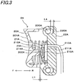
- Fig. 3 is a view illustrating the configuration of an example of a switch according to the first embodiment, and the switch 2A of the first embodiment will be described below in detail with reference to the respective drawings.
- the switch 2A is formed on the grip 12 in the vicinity of the electric-tool body 11.
- the switch 2A is provided with a trigger 20A that is manipulated by a worker, and a load sensor 21A that receives a pressing force through the trigger 20A.
- the trigger 20A is an example of the switch manipulation part, and is attached to a support part 22A attached to the grip 12 illustrated in Fig. 1 to be movable in directions indicated by arrows F and R.
- a pin 200A formed on the trigger 20A is fitted into an elongated hole 220A formed in a support part 22A, so that the trigger 20A is movably attached to the support part 22A while a moving amount and a moving direction are regulated.
- the trigger 20A has a manipulation receiving part 201A formed on an outer surface that is one side thereof to be curved in a concave shape, for example, thus making it easy to exert a force in a direction pulling the trigger by a finger.
- the trigger 20A has a pressing convex part 202A formed on an inner surface that is the other side thereof to protrude in a direction of the load sensor 21A.
- the switch 2A includes a coil spring 23A between the trigger 20A and a support part 22A.
- the trigger 20A is biased in a direction where it moves away from the load sensor 21A, that is, a direction of arrow F, by the coil spring 23A.
- the switch 2A is operates as follows: when a forefinger that is a predetermined finger of a hand holding the grip 12 illustrated in Fig. 1 applies a force in a direction pulling the trigger 20A, the coil spring 23A is compressed and the trigger 20A is moved in the direction indicated by the arrow R. When a force pulling the trigger 20A becomes weak, the trigger 20A is moved in the direction indicated by the arrow F by the restoring force of the coil spring 23A.
- Figs. 5 and 6 are views illustrating the configuration of an example of a load sensor according to the first embodiment.
- the load sensor 21A includes a pressure-sensitive conductive elastic member 210A that is changed in electric conductivity depending on a load, and a substrate 211A that forms variable resistance having a resistance value that varies depending on a change in electric conductivity of the pressure-sensitive conductive elastic member 210A.
- a sealing cover 212A covering the pressure-sensitive conductive elastic member 210A and the substrate 211A is attached to the load sensor 21 A.
- the pressure-sensitive conductive elastic member 210A is made by dispersing conductive particles such as carbon in a non-conductive elastic material such as rubber.
- the pressure-sensitive conductive elastic member 210A has a plate shape, is elastically deformable in a direction in which it is bent when receiving a load, and in addition, is elastically deformable in a direction in which it is compressed.
- the substrate 211A has a pair of conductive patterns that are formed on an outer surface that is one surface facing the pressure-sensitive conductive elastic member 210A to be insulated from each other. Wiring 213A is connected to each conductive pattern.
- the sealing cover 212A includes a pressing part 214A that presses the pressure-sensitive conductive elastic member 210A, a seal part 215A that seals a periphery of the substrate 211A, and a support part 216A that supports the pressure-sensitive conductive elastic member 210A against the substrate 211A.
- the pressing part 214A, the seal part 215A and the support part 216A are integrally formed of the elastic material such as rubber.
- an internal space 218A is formed to face the pressure-sensitive conductive elastic member 210A.
- a portion of the pressing part 214A facing the pressure-sensitive conductive elastic member 210A in the internal space 218A includes a convex portion that protrudes in a direction of the pressure-sensitive conductive elastic member 210A.
- the sealing cover 212A is formed integrally with the seal part 215A, with a flexible part 217A being provided around the pressing part 214A.
- the flexible part 217A is formed to be thinner than the pressing part 214A and the seal part 215A, and does not inhibit the pressing part 214A from being elastically deformed in a direction in which it is separated from the pressure-sensitive conductive elastic member 210A.
- the seal part 215A is shaped to seal a side of the substrate 211A and a surface in the vicinity of the side.
- the support part 216A protrudes from an inner peripheral portion of the seal part 215A between the pressure-sensitive conductive elastic member 210A and the substrate 211 A, and supports a peripheral portion of the pressure-sensitive conductive elastic member 210A against the substrate 211 A.
- the load sensor 21A is attached to the support part 22A in a direction where the sealing cover 212A faces the trigger 20A.
- the load sensor 21A is attached to the support part 22A, for example, through an attaching member (not illustrated) that is formed as an integral or independent component.
- the load sensor 21A may be attached to the support part 22A by an adhesive.
- a first malfunction suppressing space L1 is formed between the pressing convex part 202A of the trigger 20A and the sealing cover 212A of the load sensor 21A.
- a second malfunction suppressing space L2 is formed between the pressing part 214A of the sealing cover 212A and the pressure-sensitive conductive elastic member 210A.
- an insulating space L3 is formed between the pressure-sensitive conductive elastic member 210A and the substrate 211A.
- a resistance value of the load sensor 21A is infinite, and the load sensor 21A is in a non-conduction state.
- the trigger 20A when the trigger 20A is pulled, the trigger 20A is moved in the direction of arrow R, so that the first malfunction suppressing space L1 is reduced and the pressing convex part 202A comes into contact with the sealing cover 212A.
- the pressing convex part 202A of the trigger 20A presses the sealing cover 212A, so that the second malfunction suppressing space L2 is reduced and the pressing part 214A of the sealing cover 212A comes into contact with the pressure-sensitive conductive elastic member 210A.
- the pressure-sensitive conductive elastic member 210A When the trigger 20A is further pulled, the pressure-sensitive conductive elastic member 210A is pressed through the trigger 20A and the sealing cover 212A, so that the pressure-sensitive conductive elastic member 210A is elastically deformed in a direction where it is bent, the insulating space L3 is reduced, and the pressure-sensitive conductive elastic member 210A comes into contact with the substrate 211 A.
- the pressure-sensitive conductive elastic member 210A When the trigger 20A is further pulled, the pressure-sensitive conductive elastic member 210A is pressed through the trigger 20A and the sealing cover 212A, so that the pressure-sensitive conductive elastic member 210A is elastically deformed in a direction where it is compressed, in the state where the pressure-sensitive conductive elastic member 210A is in contact with the substrate 211A.
- the load sensor 21A has characteristics in which the resistance value varies according to a deformation amount, when the pressure-sensitive conductive elastic member 210A is pressed and deformed.
- the load sensor 21A assumes a conduction state.
- the load is further increased when the load sensor 21A is in the conduction state, the deformation amount of the pressure-sensitive conductive elastic member 210A is increased and the resistance value is further reduced.
- the pressure-sensitive conductive elastic member 210A is pressed through the trigger 20A, the sum of the first malfunction suppressing space L1, the second malfunction suppressing space L2 and the insulating space L3 is less than the moving amount L4 of the trigger 20A.
- the first malfunction suppressing space L1 and the second malfunction suppressing space L2 may not be formed.
- the first malfunction suppressing space L1 and the second malfunction suppressing space L2 are formed.
- the insulating space L3 may be sensuously considered to be "0", in the manipulation of pulling the trigger 20A with a person's finger.
- the moving amount L4 of the trigger 20A is set to be 0 mm or more and 3 mm or less.
- the moving amount L4 of the trigger 20A is set to be 3 mm or less, a person rarely feels a manipulation amount when pulling the trigger 20A by his or her finger. Hence, it becomes easy to control the number of rotations of the motor M according to the intensity of a force pulling the trigger 20A.
- the switch 2A using the load sensor 21A equipped with the pressure-sensitive conductive elastic member 210A it is unnecessary to have a mechanical variable resistor, such as a sliding resistor or a rotary resistor.
- a mechanical variable resistor such as a sliding resistor or a rotary resistor.
- the stroke of the trigger is determined by a movable range of the variable resistor.
- a degree of freedom upon determining the stroke of the trigger 20A is improved.
- the switch 2A is configured such that the trigger 20A is movable. However, this employs the load sensor 21A having the pressure-sensitive conductive elastic member 210A. Thus, when comparing this configuration with the configuration having the mechanical variable resistor, the former may reduce the number of moving components, and may achieve a reduction in size of the switch 2A. The reduction in size of the switch 2A may improve a degree of freedom upon placing the trigger 20A. For example, in addition to a normal position where the switch may be manipulated by the forefinger of the hand holding the grip 12, the switch 2A may be additionally provided on a lower portion of the grip 20, thus allowing another trigger 20A to be manipulated even on the lower portion of the grip 20.
- the switch 2A may be additionally provided on the electric-tool body 11, thus allowing another trigger 20A to be manipulated even on the electric-tool body 11. Therefore, it is possible to change a method of holding the tool according to the kind of work and to lessen a workload.
- Figs. 6 and 7 are views illustrating the configuration of an example of a switch according to the second embodiment
- Figs. 8 and 9 are views illustrating the configuration of an example of a sensor unit according to the present embodiment.
- the switch 2B of the second embodiment will be described in detail with reference to the respective drawings.
- the switch 2B is formed on the grip 12 in the vicinity of the electric-tool body 11.
- the switch 2B includes a trigger 20B that is manipulated by a worker, and a sensor unit 24B having a load sensor 21B that receives a pressing force through the trigger 20B.
- the trigger 20B is an example of the switch manipulation part, and is attached to a support part 22B attached to the grip 12 illustrated in Fig. 1 to be movable in directions indicated by arrows F and R.
- a pin 200B formed on the trigger 20B is fitted into an elongated hole 220B formed in a support part 22B, so that the trigger 20B is movably attached to the support part 22B while a moving amount and a moving direction are regulated.
- the trigger 20B has a manipulation receiving part 201B formed on an outer surface that is one side thereof to be curved in a concave shape, for example, thus making it easy to exert a force in a direction pulling the trigger by a finger.
- the trigger 20B has a pressing convex part 202B formed on an inner surface that is the other side thereof to protrude in a direction of the load sensor 21B.
- the switch 2B includes a coil spring 23B between the trigger 20B and the sensor unit 24B.
- the trigger 20B is biased in a direction where it moves away from the load sensor 21B, that is, a direction of arrow F, by the coil spring 23B.
- the switch 2B is operates as follows: when a forefinger that is a predetermined finger of a hand holding the grip 12 illustrated in Fig. 1 applies a force in a direction pulling the trigger 20B, the coil spring 23B is compressed and thereby the trigger 20B is moved in the direction indicated by the arrow R. When a force pulling the trigger 20B becomes weak, the trigger 20B is moved in the direction indicated by the arrow F by the restoring force of the coil spring 23B.
- Fig. 10 is a view illustrating the configuration of an example of a load sensor according to the second embodiment.
- the load sensor 21B includes a pressure-sensitive conductive elastic member 210B that is changed in electric conductivity depending on a load, and a substrate 211B that forms variable resistance having a resistance value that varies depending on a change in electric conductivity of the pressure-sensitive conductive elastic member 210B.
- a sealing cover 212B covering the pressure-sensitive conductive elastic member 210B and the substrate 211 B is attached to the load sensor 21B.
- the pressure-sensitive conductive elastic member 210B is made by dispersing conductive particles such as carbon in a non-conductive elastic material such as rubber.
- the pressure-sensitive conductive elastic member 210B has a plate shape, is elastically deformable in a direction in which it is bent when receiving a load, and in addition, is elastically deformable in a direction in which it is compressed.
- the substrate 211B has a pair of conductive patterns that are formed on an outer surface that is one surface facing the pressure-sensitive conductive elastic member 210B to be insulated from each other. Wiring 213B is connected to each conductive pattern.
- the substrate 211B includes a connecting portion 219B that has a diameter allowing air to pass therethrough and penetrates inner and outer surfaces.
- the sealing cover 212B includes a pressing part 214B that presses the pressure-sensitive conductive elastic member 210B, a seal part 215B that seals a periphery of the substrate 211B, and a support part 216B that supports the pressure-sensitive conductive elastic member 210B against the substrate 211B.
- the pressing part 214B, the seal part 215B and the support part 216B are integrally formed of the elastic material such as rubber.
- an internal space 218B is formed to face the pressure-sensitive conductive elastic member 210B.
- a portion of the pressing part 214B facing the pressure-sensitive conductive elastic member 210B in the internal space 218B includes a convex portion that protrudes in a direction of the pressure-sensitive conductive elastic member 210B.
- the sealing cover 212B is formed integrally with the seal part 215B, with a flexible part 217B being provided around the pressing part 214B.
- the flexible part 217B is formed to be thinner than the pressing part 214B and the seal part 215B, and does not inhibit the pressing part 214B from being elastically deformed in a direction in which it is separated from the pressure-sensitive conductive elastic member 210B.
- the seal part 215B is shaped to seal a side of the substrate 211B and a surface in the vicinity of the side.
- the support part 216B protrudes from an inner peripheral portion of the seal part 215B between the pressure-sensitive conductive elastic member 210B and the substrate 211B, and supports a peripheral portion of the pressure-sensitive conductive elastic member 210B against the substrate 211B.
- the sensor unit 24B includes a preventing member 240B to suppress foreign matter from entering from surroundings to the load sensor 21B.
- the preventing member 240B includes a load-sensor cover member 241B that exposes the sealing cover 212B and covers one side of the load sensor 21B, and a load-sensor support member 242B that seals an opposite surface of the sealing cover 212B, which is another side of the load sensor 21B.
- the load-sensor cover member 241B includes an opening 243B that is formed in a portion facing the pressing part 214B of the sealing cover 212B to pass through inner and outer surfaces of the load-sensor cover member 241B.
- the load-sensor cover member 241B forms, on a side facing the load-sensor support member 242B, a recess having a shape that matches that of the seal part 215B of the sealing cover 212B, thus including a holding portion 244B.
- the load-sensor cover member 241B has a sealing surface 245B at a portion facing the load-sensor support member 242B on an outside of the holding portion 244B, and has a screw-hole portion 246B that passes through the sealing surface 245B.
- the load-sensor support member 242B forms, on the inner surface of the load sensor 21B, a closed space 247B that has a predetermined volume for the internal space 218B.
- the load-sensor support member 242B includes a sealing surface 248B on a portion facing the load-sensor cover member 241B outside of the closed space 247B, and includes a hole portion 249B passing through the sealing surface 248B, in addition to the screw-hole portion 246B.
- the sensor unit 24B comes into contact with the sealing surface 245B of the load-sensor cover member 241B and the sealing surface 248B of the load-sensor support member 242B, in the state where a portion of an inner surface of the substrate 211B of the load sensor 21B comes into contact with a portion of the sealing surface 248B of the load-sensor support member 242B and the sealing cover 212B of the load sensor 21B is put into the holding portion 244B of the load-sensor cover member 241B.
- the load sensor 21B is held between the load-sensor cover member 241B and the load-sensor support member 242B.
- the sealing cover 212B assumes the following state: an outer surface that is one surface of the seal part 215B is in pressure contact with the load-sensor cover member 241B, the inner surface that is another surface of the seal part 215B is in pressure contact with the load-sensor support member 242B, and the seal part 215B is compressed by a predetermined amount.
- the load sensor 21B is provided inside the seal part 215B such that the substrate 211B is held between the load-sensor cover member 241B and the load-sensor support member 242B. Therefore, the sealing cover 212B functions as a sealer between the sealing surface 245B of the load-sensor cover member 241B and the sealing surface 248B of the load-sensor support member 242B.
- the sealing surface 245B of the load-sensor cover member 241B is in pressure contact with the sealing surface 248B of the load-sensor support member 242B, and the seal part 215B of the sealing cover 212B is compressed, so that the internal space 218B of the load sensor 21B is sealed and the closed space 247B is also sealed.
- a portion of the sensor unit 24A through which the wiring 213B of the load sensor 21B is taken out is sealed by the sealer 27B.
- the sensor unit 24B is configured to prevent moisture or dust from entering into the internal space 218B of the load sensor 21B and to prevent moisture or dust from entering into the inner surface of the substrate 211B, it is possible to realize the waterproof and dustproof structure for the pressure-sensitive conductive elastic member 210B and the substrate 211 B of the load sensor 21B.
- the sensor unit 24B is configured such that the internal space 218B and the closed space 247B between which the substrate 211B of the load sensor 21B is connected with each other via the connecting portion 219B, and air flows between the internal space 218B and the closed space 247B.
- the sensor unit 24B is attached to the support part 22B to be movable in the moving direction of the trigger 20B as well as in the directions indicated by arrows F and R.
- the coil spring 26B is fitted between the sensor unit 24B and the support part 22B, so that the sensor unit is biased in the direction of arrow F, namely, a direction in which it approaches the trigger 20B.
- a regulation part 250B enters a pin 221B formed on the support part 22B, thus regulating the moving amount of the sensor unit 24B in the direction of arrow F when it is biased by the coil spring 26B, and the moving amount of the sensor unit in the direction of arrow R when it is pressed through the trigger 20B.
- the sensor unit 24B, the coil spring 26B, the pin 221B, the regulation part 250B and the like constitute a load release mechanism.
- the pressing convex part 202B of the trigger 20B enters the opening 243B of the load-sensor cover member 241B constituting the sensor unit 24B, and faces the sealing cover 212B of the load sensor 21B.
- a first malfunction suppressing space L1 is formed between the pressing convex part 202B of the trigger 20B and the sealing cover 212B of the load sensor 21B.
- a second malfunction suppressing space L2 is formed between the pressing part 214B of the sealing cover 212B and the pressure-sensitive conductive elastic member 210B.
- an insulating space L3 is formed between the pressure-sensitive conductive elastic member 210B and the substrate 211B.
- the trigger 20B when the trigger 20B is pulled, the trigger 20B is moved in the direction of arrow R, so that the first malfunction suppressing space L1 is reduced and the pressing convex part 202B comes into contact with the sealing cover 212B.
- the pressing convex part 202B of the trigger 20B presses the sealing cover 212B, so that the second malfunction suppressing space L2 is reduced and the pressing part 214B of the sealing cover 212B comes into contact with the pressure-sensitive conductive elastic member 210B.
- the pressure-sensitive conductive elastic member 210B When the trigger 20B is further pulled, the pressure-sensitive conductive elastic member 210B is pressed through the trigger 20B and the sealing cover 212B, so that the pressure-sensitive conductive elastic member 210B is elastically deformed in a direction where it is bent, the insulating space L3 is reduced, and the pressure-sensitive conductive elastic member 210B comes into contact with the substrate 211B.
- the pressure-sensitive conductive elastic member 210B When the trigger 20B is further pulled, the pressure-sensitive conductive elastic member 210B is pressed through the trigger 20B and the sealing cover 212B, so that the pressure-sensitive conductive elastic member 210B is elastically deformed in a direction where it is compressed, in the state where the pressure-sensitive conductive elastic member 210B is in contact with the substrate 211B.
- the load sensor 21B has characteristics in which the resistance value varies depending on a deformation amount, when the pressure-sensitive conductive elastic member 210B is pressed and deformed.
- the load sensor 21B assumes a conduction state.
- the load is further increased when the load sensor 21B is in the conduction state, the deformation amount of the pressure-sensitive conductive elastic member 210B is increased and the resistance value is further reduced.
- the pressure-sensitive conductive elastic member 210B is pressed through the trigger 20B, the sum of the first malfunction suppressing space L1, the second malfunction suppressing space L2 and the insulating space L3 is less than the moving amount L4 of the trigger 20B.
- the first malfunction suppressing space L1 and the second malfunction suppressing space L2 may not be formed.
- the first malfunction suppressing space L1 and the second malfunction suppressing space L2 are formed.
- the insulating space L3 may be sensuously considered to be "0", in the manipulation of pulling the trigger 20B with a person's finger.
- the moving amount L4 of the trigger 20B is set to be 0 mm or more and 3 mm or less.
- the moving amount L4 of the trigger 20B is set to be 3 mm or less, a person rarely feels a manipulation amount when pulling the trigger 20B by his or her finger. Hence, it becomes easy to control the number of rotations of the motor M according to the intensity of a force pulling the trigger 20B.
- the switch 2B is configured such that a reaction force of the coil spring 26B biasing the sensor unit 24B is stronger than that of the coil spring 23B biasing the trigger 20B.
- the trigger 20B is moved in the direction of arrow R, so that the pressure-sensitive conductive elastic member 210B is pressed through the trigger 20B and the sealing cover 212B.
- L4 a maximum
- the load sensor 21B may be retracted in the direction of arrow R, and it is possible to suppress a load exceeding a predetermined level from being applied to the load sensor 21B.
- the sealing cover 212B In the switch 2B, when the trigger 20B presses the sealing cover 212B, the volume of the internal space 218B is reduced. In the sensor unit 24B, the sealing surface 245B of the load-sensor cover member 241B is in pressure contact with the sealing surface 248B of the load-sensor support member 242B, so that the closed space 247B is sealed but is not perfectly sealed.
- the internal space 218B and the closed space 247B are configured to be connected with each other via the connecting portion 219B, in the state where the substrate 211B of the load sensor 21B is interposed between the internal space and the closed space.
- Such a configuration allows air of the internal space 218B to flow into the closed space 247B, when the sealing cover 212B is pressed by the trigger 20B.
- the closed space 247B has a sufficiently large volume as compared to the internal space 218B, a rise in pressure occurring when air corresponding to a volume reducing proportion of the internal space 218B flows is negligible, and the leakage of air from between the sealing surface 245B of the load-sensor cover member 241B and the sealing surface 248B of the load-sensor support member 242B is sufficiently suppressed.
- the switch 2B is configured such that the trigger 20B and the sensor unit 24B are movable, but the trigger 20B and the sensor unit 24B are independent members, and the waterproof and dustproof structure is provided in the sensor unit 24B. Thus, it is unnecessary to provide water-proofness and dust-proofness to a sliding portion, so that it is possible to realize the waterproof and dustproof structure with a simple configuration.
- Fig. 11 is a view illustrating the configuration of an example of a switch according to the third embodiment, and the switch 2C of the third embodiment will be described below in detail with reference to the respective drawings.
- the switch 2C is formed on the grip 12 in the vicinity of the electric-tool body 11.
- the switch 2C is provided with a trigger 20C that is manipulated by a worker, and a load sensor 21C that receives a pressing force through the trigger 20C.
- the trigger 20C is an example of the switch manipulation part, and is attached to a support part 22C attached to the grip 12 illustrated in Fig. 1 to be movable in directions indicated by arrows F and R.
- a pin 200C formed on the trigger 20C is fitted into an elongated hole 220C formed in a support part 22C, so that the trigger 20C is movably attached to the support part 22C while a moving amount and a moving direction are regulated.
- the trigger 20C has a manipulation receiving part 201C formed on an outer surface that is one side thereof to be curved in a concave shape, for example, thus making it easy to exert a force in a direction pulling the trigger by a finger.
- the trigger 20C has a pressing convex part 202C formed on an inner surface that is the other side thereof to protrude in a direction of the load sensor 21 C.
- the switch 2C includes a coil spring 23C between the trigger 20C and a support part 22C.
- the trigger 20C is biased in a direction where it moves away from the load sensor 21C, that is, a direction of arrow F, by the coil spring 23C.
- the switch 2C is operates as follows: when a forefinger that is a predetermined finger of a hand holding the grip 12 illustrated in Fig. 1 applies a force in a direction pulling the trigger 20C, the coil spring 23C is compressed and the trigger 20C is moved in the direction indicated by the arrow R. When a force pulling the trigger 20C becomes weak, the trigger 20C is moved in the direction indicated by the arrow F by the restoring force of the coil spring 23C.
- the load sensor 21C includes a pressure-sensitive conductive elastic member 210C that is changed in electric conductivity depending on a load, a substrate 211C that forms variable resistance having a resistance value that varies depending on a change in electric conductivity of the pressure-sensitive conductive elastic member 210C, and a sealing cover 212C covering the pressure-sensitive conductive elastic member 210C and the substrate 211C.
- the pressure-sensitive conductive elastic member 210C is made by dispersing conductive particles such as carbon in a non-conductive elastic material such as rubber.
- the pressure-sensitive conductive elastic member 210C has a plate shape, is elastically deformable in a direction in which it is bent when receiving a load, and in addition, is elastically deformable in a direction in which it is compressed.
- the substrate 211C has a pair of conductive patterns that are formed on an outer surface that is one surface facing the pressure-sensitive conductive elastic member 210C to be insulated from each other. Wiring 213C is connected to each conductive pattern.
- the pressure-sensitive conductive elastic member 210C is attached to the substrate 211C via the support part 216C.
- the support part 216C is made up of a non-conductive member, and supports a periphery of the pressure-sensitive conductive elastic member 210C again the substrate 211C.
- the sealing cover 212C is made of a non-conductive elastic material such as rubber, and integrally covers the pressure-sensitive conductive elastic member 210C, the substrate 211C, and the support part 216C such that the wiring 213C is taken out.
- the load sensor 21C is attached to the support part 22C in a direction where the pressure-sensitive conductive elastic member 210C is located on the substrate 211C towards the trigger 20C.
- the load sensor 21C is attached to the support part 22C, for example, through an attaching member (not illustrated) that is formed as an integral or independent component.
- the load sensor 21C may be attached to the support part 22C by an adhesive.
- a malfunction suppressing space L1 is formed between the pressing convex part 202C of the trigger 20C and the sealing cover 212C of the load sensor 21C.
- an insulating space L3 is formed between the pressure-sensitive conductive elastic member 210C and the substrate 211C.
- the trigger 20C when the trigger 20C is pulled, the trigger 20C is moved in the direction of arrow R, so that the malfunction suppressing space L1 is reduced and the pressing convex part 202C comes into contact with the sealing cover 212C.
- the pressing convex part 202C of the trigger 20C presses the sealing cover 212C, so that the sealing cover 212C is elastically deformed in a direction where it is bent and the pressure-sensitive conductive elastic member 210C is pressed.
- the pressure-sensitive conductive elastic member 210C When the trigger 20C is further pulled, the pressure-sensitive conductive elastic member 210C is pressed through the trigger 20C and the sealing cover 212C, so that the pressure-sensitive conductive elastic member 210C is elastically deformed in a direction where it is bent, the insulating space L3 is reduced, and the pressure-sensitive conductive elastic member 210C comes into contact with the substrate 211C.
- the pressure-sensitive conductive elastic member 210C When the trigger 20C is further pulled, the pressure-sensitive conductive elastic member 210C is pressed through the trigger 20C and the sealing cover 212C, so that the pressure-sensitive conductive elastic member 210C is elastically deformed in a direction where it is compressed, in the state where the pressure-sensitive conductive elastic member 210C is in contact with the substrate 211C.
- the load sensor 21C has characteristics in which the resistance value varies depending on a deformation amount, when the pressure-sensitive conductive elastic member 210C is pressed and deformed.
- the load sensor 21C assumes a conduction state.
- the load is further increased when the load sensor 21C is in the conduction state, the deformation amount of the pressure-sensitive conductive elastic member 210C is increased and the resistance value is further reduced.
- the pressure-sensitive conductive elastic member 210C is pressed through the trigger 20C, the sum of the malfunction suppressing space L1 and the insulating space L3 is less than the moving amount L4 of the trigger 20C.
- the malfunction suppressing space L1 may not be formed.
- the malfunction suppressing space L1 is formed in consideration of a possibility that a load is applied to the pressure-sensitive conductive elastic member 210C by the dimensional tolerance of each component and the accumulation of tolerance when respective components are assembled with each other, in the initial state where the trigger 20C is not pressed.
- the insulating space L3 may be sensuously considered to be "0", in the manipulation of pulling the trigger 20C with a person's finger.
- the moving amount L4 of the trigger 20C is set to be 0 mm or more and 3 mm or less.
- the moving amount L4 of the trigger 20C is set to be 3 mm or less, a person rarely feels a manipulation amount when pulling the trigger 20C by his or her finger. Hence, it becomes easy to control the number of rotations of the motor M according to the intensity of a force pulling the trigger 20C.
- the pressure-sensitive conductive elastic member 210C and the substrate 211C are sealed by the sealing cover 212C, it is possible to realize the waterproof and dustproof structure with a simple configuration. Since the sealing cover 212C is interposed between the load sensor 21C and the support part 22C, the pressure-sensitive conductive elastic member 210C and the substrate 211C may be retracted in the direction of arrow R by the elasticity of the sealing cover 212C when a force exceeding a predetermined level is exerted on the trigger 20C, and a load release mechanism may be realized with a simple configuration.
- Fig. 12 is a view illustrating the configuration of an example of a switch according to the fourth embodiment, and the switch 2D of the fourth embodiment will be described below in detail with reference to the respective drawings.
- the switch 2D is formed on the grip 12 in the vicinity of the electric-tool body 11.
- the switch 2D is provided with a trigger 20D that is manipulated by a worker, and a load sensor 21D that receives a pressing force through the trigger 20D.
- the trigger 20D is an example of the switch manipulation part, and is attached to a support part 22D attached to the grip 12 illustrated in Fig. 1 to be movable in directions indicated by arrows F and R.
- a pin 200D formed on the trigger 20D is fitted into an elongated hole 220D formed in a support part 22D, so that the trigger 20D is movably attached to the support part 22D while a moving amount and a moving direction are regulated.
- the trigger 20D has a manipulation receiving part 201D formed on an outer surface that is one side thereof to be curved in a concave shape, for example, thus making it easy to exert a force in a direction pulling the trigger by a finger.
- the trigger 20D has, on an inner surface that is the other side thereof, a support convex part 202D to which the load sensor 21D is attached.
- the switch 2D includes a coil spring 23D between the trigger 20D and a support part 22D.
- the trigger 20D is biased in a direction where it moves away from the support part 22D, that is, a direction of arrow F, by the coil spring 23D.
- the switch 2D is operates as follows: when a forefinger that is a predetermined finger of a hand holding the grip 12 illustrated in Fig. 1 applies a force in a direction pulling the trigger 20D, the coil spring 23D is compressed and the trigger 20D is moved in the direction of the arrow R. When a force pulling the trigger 20D becomes weak, the trigger 20D is moved in the direction of the arrow F by the restoring force of the coil spring 23D.
- the load sensor 21D has the same configuration as the load sensor 21A illustrated in Fig. 4 , and includes a pressure-sensitive conductive elastic member 210D that is changed in electric conductivity depending on a load, and a substrate 211D that forms variable resistance having a resistance value that varies depending on a change in electric conductivity of the pressure-sensitive conductive elastic member 210D.
- a sealing cover 212D covering the pressure-sensitive conductive elastic member 210D and the substrate 211D is attached to the load sensor 21D.
- the pressure-sensitive conductive elastic member 210D is made by dispersing conductive particles such as carbon in a non-conductive elastic material such as rubber.
- the pressure-sensitive conductive elastic member 210D has a plate shape, is elastically deformable in a direction in which it is bent when receiving a load, and in addition, is elastically deformable in a direction in which it is compressed.
- the substrate 211D has a pair of conductive patterns that are formed on an outer surface that is one surface facing the pressure-sensitive conductive elastic member 210D to be insulated from each other.
- Wiring 213D is connected to each conductive pattern.
- the wiring 213D is connected with wiring 29D of the body by a connector 28D having a waterproof structure, for example.
- the sealing cover 212D includes a pressing part 214D that presses the pressure-sensitive conductive elastic member 210D, a seal part 215D that seals a periphery of the substrate 211D, and a support part 216D that supports the pressure-sensitive conductive elastic member 210D against the substrate 211D.
- the pressing part 214D, the seal part 215D and the support part 216D are integrally formed of the elastic material such as rubber.
- an internal space 218D is formed to face the pressure-sensitive conductive elastic member 210D.
- a portion of the pressing part 214D facing the pressure-sensitive conductive elastic member 210D in the internal space 218D includes a convex portion that protrudes in a direction of the pressure-sensitive conductive elastic member 210D.
- the sealing cover 212D is formed integrally with the seal part 215D, with a flexible part 217D being provided around the pressing part 214D.
- the flexible part 217D is formed to be thinner than the pressing part 214D and the seal part 215D, and does not inhibit the pressing part 214D from being elastically deformed in a direction in which it is separated from the pressure-sensitive conductive elastic member 210D.
- the seal part 215D is shaped to seal a side of the substrate 211D and a surface in the vicinity of the side.
- the support part 216D protrudes from an inner peripheral portion of the seal part 215D between the pressure-sensitive conductive elastic member 210D and the substrate 211D, and supports a peripheral portion of the pressure-sensitive conductive elastic member 210D against the substrate 211D.
- the load sensor 21D is attached to the support convex part 202D of the trigger 20D in a direction where the sealing cover 212D faces the support part 22D.
- a first malfunction suppressing space L1 is formed between the sealing cover 212D of the load sensor 21D and the support part 22D.
- a second malfunction suppressing space L2 is formed between the pressing part 214D of the sealing cover 212D and the pressure-sensitive conductive elastic member 210D.
- an insulating space L3 is formed between the pressure-sensitive conductive elastic member 210D and the substrate 211D.
- a resistance value of the load sensor 21D is infinite, and the load sensor 21D is in a non-conduction state.
- the trigger 20D when the trigger 20D is pulled, the trigger 20D is moved in the direction of arrow R, so that the first malfunction suppressing space L1 is reduced and the sealing cover 212D comes into contact with the support part 22D.
- the sealing cover 212D is pressed on the support part 22D, so that the second malfunction suppressing space L2 is reduced and the pressing part 214D of the sealing cover 212D comes into contact with the pressure-sensitive conductive elastic member 210D.
- the pressure-sensitive conductive elastic member 210D When the trigger 20D is further pulled, the pressure-sensitive conductive elastic member 210D is pressed through the trigger 20D and the sealing cover 212D, so that the pressure-sensitive conductive elastic member 210D is elastically deformed in a direction where it is bent, the insulating space L3 is reduced, and the pressure-sensitive conductive elastic member 210D comes into contact with the substrate 211D.
- the pressure-sensitive conductive elastic member 210D When the trigger 20D is further pulled, the pressure-sensitive conductive elastic member 210D is pressed through the trigger 20D and the sealing cover 212D, so that the pressure-sensitive conductive elastic member 210D is elastically deformed in a direction where it is compressed, in the state where the pressure-sensitive conductive elastic member 210D is in contact with the substrate 211D.
- the load sensor 21D has characteristics in which the resistance value varies depending on a deformation amount, when the pressure-sensitive conductive elastic member 210D is pressed and deformed.
- the load sensor 21D assumes a conduction state.
- the load is further increased when the load sensor 21 D is in the conduction state, the deformation amount of the pressure-sensitive conductive elastic member 210D is increased and the resistance value is further reduced.
- the pressure-sensitive conductive elastic member 210D is pressed through the trigger 20D, the sum of the first malfunction suppressing space L1, the second malfunction suppressing space L2 and the insulating space L3 is less than the moving amount L4 of the trigger 20D.
- the first malfunction suppressing space L1 and the second malfunction suppressing space L2 may not be formed.
- the first malfunction suppressing space L1 and the second malfunction suppressing space L2 are formed.
- the insulating space L3 may be sensuously considered to be "0", in the manipulation of pulling the trigger 20D with a person's finger.
- the moving amount L4 of the trigger 20D is set to be 0 mm or more and 3 mm or less.
- the moving amount L4 of the trigger 20D is set to be 3 mm or less, a person rarely feels a manipulation amount when pulling the trigger 20D by his or her finger. Hence, it becomes easy to control the number of rotations of the motor M according to the intensity of a force pulling the trigger 20D.
- the load sensor 21D is attached to the trigger 20D, so that the trigger 20D may also be replaced during the replacement of the load sensor 21D, thus improving workability.
- Fig. 13 is a view illustrating the configuration of an example of a switch according to the fifth embodiment, and the switch 2E of the fifth embodiment will be described below in detail with reference to the respective drawings.
- the switch 2E is formed on the grip 12 in the vicinity of the electric-tool body 11.
- the switch 2E is an example of the switch, and includes a trigger 20E that is manipulated by a worker, and a load sensor 21E that receives a pressing force through the trigger 20E.
- the trigger 20E is an example of the switch manipulation part, and is attached to a support part 22E attached to the grip 12 illustrated in Fig. 1 to be movable in directions indicated by arrows F and R.
- a pin 200E attached to the trigger 20E is fitted into an elongated hole 220E formed in a support part 22E, so that the trigger 20E is movably attached to the support part 22E while a moving amount and a moving direction are regulated.
- the trigger 20E has a manipulation receiving part 201E formed on an outer surface that is one side thereof to be curved in a concave shape, for example, thus making it easy to exert a force in a direction pulling the trigger by a finger.
- the trigger 20E has, on an inner surface that is the other side thereof, a support convex part 202E to which a pressure-sensitive conductive elastic member 210E of the load sensor 21 E is attached.
- the switch 2E includes a coil spring 23E between the trigger 20E and a support part 22E.
- the trigger 20E is biased in a direction where it moves away from the support part 22E, that is, a direction of arrow F, by the coil spring 23E.
- the switch 2E is operates as follows: when a forefinger that is a predetermined finger of a hand holding the grip 12 illustrated in Fig. 1 applies a force in a direction pulling the trigger 20E, the coil spring 23E is compressed and the trigger 20E is moved in the direction of the arrow R. When a force pulling the trigger 20E becomes weak, the trigger 20E is moved in the direction of the arrow F by the restoring force of the coil spring 23E.
- the load sensor 21E includes the pressure-sensitive conductive elastic member 210E that is changed in electric conductivity depending on a load, and a substrate 211E that forms variable resistance having a resistance value that varies depending on a change in electric conductivity of the pressure-sensitive conductive elastic member 210E.
- the pressure-sensitive conductive elastic member 210E is made by dispersing conductive particles such as carbon in a non-conductive elastic material such as rubber.
- the pressure-sensitive conductive elastic member 210E has a plate shape and is elastically deformable in a direction in which it is compressed when receiving a load.
- the substrate 211E has a pair of conductive patterns that are formed on an outer surface that is one surface facing the pressure-sensitive conductive elastic member 210E to be insulated from each other. Wiring 213E is connected to each conductive pattern.
- the pressure-sensitive conductive elastic member 210E is attached to the support convex part 202E of the trigger 20E, and the substrate 211E is attached to the support part 22E.
- an insulating space L3 is formed between the pressure-sensitive conductive elastic member 210E and the substrate 211E.
- the insulating space L3 serves as a malfunction suppressing space.
- the trigger 20E when the trigger 20E is pulled, the trigger 20E is moved in the direction of arrow R, so that the insulating space L3 is reduced and the pressure-sensitive conductive elastic member 210E comes into contact with the substrate 211E.
- the pressure-sensitive conductive elastic member 210E When the trigger 20E is further pulled, the pressure-sensitive conductive elastic member 210E is pressed through the trigger 20E, so that the pressure-sensitive conductive elastic member 210E is elastically deformed in a direction where it is compressed, in the state where the pressure-sensitive conductive elastic member 210E is in contact with the substrate 211E.
- the load sensor 21E has characteristics in which the resistance value varies depending on a deformation amount, when the pressure-sensitive conductive elastic member 210E is pressed and deformed.
- the load sensor 21E assumes a conduction state.
- the load is further increased when the load sensor 21E is in the conduction state, the deformation amount of the pressure-sensitive conductive elastic member 210E is increased and the resistance value is further reduced.
- the insulating space L3 is smaller than the moving amount L4 of the trigger 20E.
- the insulating space L3 may be sensuously considered to be "0", in the manipulation of pulling the trigger 20E with a person's finger.
- the moving amount L4 of the trigger 20E is set to be 0 mm or more and 3 mm or less.
- the moving amount L4 of the trigger 20E is set to be 3 mm or less, a person rarely feels a manipulation amount when pulling the trigger 20E by his or her finger. Hence, it becomes easy to control the number of rotations of the motor M according to the intensity of a force pulling the trigger 20E.
- the pressure-sensitive conductive elastic member 210E of the load sensor 21E is attached to the trigger 20E, so that the trigger 20E may also be replaced during the replacement of the pressure-sensitive conductive elastic member 210E, thus improving workability. Since the entire load sensor 21E is not replaced with another one, cost is saved.
- the switches 2A to 2E are simply referred to as the switch 2, and the load sensors 21A to 21E are simply referred to as the load sensor 21.
- the pressure-sensitive conductive elastic members 210A to 210E are simply referred to as the pressure-sensitive conductive elastic member 210, and the substrates 211A to 211E are simply referred to as the substrate 211.
- the control unit 3 detects a resistance value R of the load sensor 21 that is changed when the pressure-sensitive conductive elastic member 210 is pressed by the manipulation of the switch 2, and then outputs a control signal Dd depending on the detected resistance value. Since the resistance value R of the load sensor 21 is changed by the force pressing the trigger 20, it is possible to control the motor M in response to a control signal Dd due to acceleration/deceleration manipulation of the trigger 20 by a user.
- An illumination system such as an LED may be prepared as the electric component.
- the control circuit 4 is an activation circuit of the control unit 3, and forms a circuit that causes an electric current to flow from the power supply unit 5 to the control unit 3 when the resistance value R of the load sensor 21 is reduced from an initial value by a predetermined amount, when the pressure-sensitive conductive elastic member 210 is pressed by manipulating the switch 2.
- the control circuit 4 includes, for example, a first switch circuit 41 that is a first switch unit including a transistor Tr1, a resistor or the like, and a second switch circuit 42 that is a second switch unit including a transistor Tr2, a resistor or the like.
- the resistance value of the load sensor 21 is infinite and the load sensor 21 is in a non-conduction state.
- the transistor Tr1 of the first switch circuit 41 is in an OFF state and no electric current flows in the transistor Tr1
- power is not fed from the power supply unit 5 to a power supply driver 53, and a predetermined voltage is not applied from the power supply driver 53 to the control unit 3.
- the transistor Tr2 of the second switch circuit 42 is in an OFF state, and no electric current flows in the transistor Tr2. Therefore, a state where power is interrupted is realized.
- the switch 2 when the trigger 20 is pulled, the insulating space L3 is reduced, and the pressure-sensitive conductive elastic member 210 comes into contact with the substrate 211.
- the trigger 20 is further pulled and the pressure-sensitive conductive elastic member 210 coming into contact with the substrate 211 is deformed in a direction where it is compressed by a predetermined amount, the load sensor 21 is in a conduction state.
- the transistor Tr1 of the first switch circuit 41 When the load sensor 21 is in the conduction state, the transistor Tr1 of the first switch circuit 41 is in an ON state and an electric current flows in the transistor Tr1. As the electric current flows in the transistor Tr1, power is fed from the power supply unit 5 to the power supply driver 53, and a predetermined voltage Vcc is applied from the power supply driver 53 to the control unit 3. The control unit 3 is activated.
- control unit 3 may be activated in the initial state where the load applied to the load sensor 21 through the trigger 20 is low.
- the resistance value R varies depending on the load applied to the pressure-sensitive conductive elastic member 210 through the trigger 20.
- the control unit 3 inputs the resistance value R of the load sensor 21 from a resistance-value detection circuit 44, outputs a control signal Dd, which depends on the resistance value R of the load sensor 21 and controls an output value of pulse width modulation (PWM), for example, to a driving circuit 6, and controls the motor M.
- PWM pulse width modulation
- the load sensor 21 When the force for pulling the trigger 20 is reduced and the load sensor is restored to the state where the insulating space L3 is formed between the pressure-sensitive conductive elastic member 210 and the substrate 211, the load sensor 21 is in the non-conduction state.
- the control unit 3 When it is determined that the resistance value R of the load sensor 21 has a predetermined value, namely, an infinite value in the present example, the control unit 3 outputs the control signal Dd to stop rotating the motor M.
- the motor M stops rotating.
- the control unit 3 continues to output the power supply maintenance signal Dk.
- the control unit 3 continues to output the power supply maintenance signal Dk.
- the control unit 3 stops outputting the power supply maintenance signal Dk.
- the transistor Tr2 in the second switch circuit 42 is in the OFF state and no electric current flows in the transistor Tr2.
- the transistor Tr1 in the first switch circuit 41 is in the OFF state. Since both the first switch circuit 41 and the second switch circuit 42 are in the OFF state, power is not fed from the power supply unit 5 to the power supply driver 53, and voltage Vcc is not applied from the power supply driver 53 to the control unit 3. Therefore, a state where power is interrupted is realized.
- control unit 3 it is unnecessary to form a switch different from the load sensor 21, and it is possible to activate the control unit 3 and control the motor M by the control unit 3, with one set of switches 2 using the load sensor 21.
- the reduction in size of the switch 2 may decrease an area in the grip 12 occupied by the switch 2, and consequently may achieve a reduction in size of the entire apparatus.
- a moving amount L4 that is a stroke of the trigger 20 required to operate the control circuit 4 is not limited particularly as long as it is possible to secure at least the insulating space L3 descried in each embodiment, and the moving amount L4 of the trigger 20 may be set to be smaller than that of a conventional sliding type switch. Furthermore, since the moving amount L4 of the trigger 20 may be selected depending on the presence of the first malfunction suppressing space L1 and the second malfunction suppressing space L2 and the amounts of the first malfunction suppressing space L1 and the second malfunction suppressing space L2, a degree of freedom upon determining the moving amount L4 of the trigger 20 is improved.
- the load sensor may be configured such that conductive patterns are formed on both sides of the pressure-sensitive conductive elastic member, and the pressure-sensitive conductive elastic member is elastically deformed in a direction where it is compressed, thus changing a conduction state on the inner and outer surfaces of the pressure-sensitive conductive elastic member and the resistance value.
- Fig. 14 is a view illustrating an overall configuration of an alternative of an electric tool according to the present embodiment
- Fig. 15 is a block diagram illustrating an example of a circuit configuration of the alternative of the electric tool according to the present embodiment.
- the electric tool 1F has a variable capacitance load sensor 21F as the switch 2F.
- the variable capacitance load sensor 21F has a pair of conductors on opposite sides of a dielectric, thus constituting a capacitor.
- One side of the pair of conductors of the load sensor 21F is formed of an elastic material, for example, and a distance between the conductors is changed as load is applied in a predetermined direction where the conductors come close to each other. Further, a distance between the conductors is changed depending on the magnitude of the load, so that the capacitance C is changed.
- the load sensor 21F sets its capacitance C to 0 when no load is applied thereto, and the capacitance C is increased in proportion to an increase in load. Further, the capacitance C that is increased in proportion to the increase in load is reduced in proportion to a reduction in load.
- the switch 2F is configured to be movable in directions where a trigger 20F comes close to or moves away from the load sensor 21F. In a state where no trigger 20F is pulled, the load sensor 21F is kept unloaded.
- the switch 2F when the trigger 20F is pulled by a person's finger, the load sensor 21F is pressed by the trigger 20F, and load acting on the load sensor 21F is changed according to the intensity of a force pulling the trigger 20F.
- the switch 2F when the force pulling the trigger 20F is increased, the load acting on the load sensor 21F is increased, so that the capacitance C of the load sensor 21F is increased.
- the switch 2F when the force pulling the trigger 20F is reduced, the load acting on the load sensor 21F is reduced, so that the capacitance C of the load sensor 21F is reduced.
- the control unit 3F detects the capacitance C of the load sensor 21F that is changed when the load sensor 21F is pressed by the manipulation of the trigger 20F, and then outputs a control signal Dd depending on the detected capacitance C. Since the capacitance C of the load sensor 21F is changed by the load acting on the load sensor 21F, the control signal Dd changed depending on an increase or reduction in force of a user manipulating the trigger 20F is output, and a motor M may be controlled depending on an increase or reduction in force manipulating the trigger 20F.
- the control circuit 4F is an activation circuit of the control unit 3F, and forms a circuit that causes an electric current to flow from the power supply unit 5 to the control unit 3F if the capacitance C of the load sensor 21F is increased from an initial value by a predetermined amount, when the load sensor 21F is pressed by manipulating the switch 2F.
- the control circuit 4F includes, for example, a first switch circuit 41F that is a first switch unit including a transistor Tr1, a resistor or the like, and a second switch circuit 42F that is a second switch unit including a transistor Tr2, a resistor or the like.
- the capacitance C of the load sensor 21F is zero.
- the resistance value of the load sensor 21F is infinite and the load sensor 21F is in a non-conduction state. Since no current flows in the load sensor 21F, the transistor Tr1 of the first switch circuit 41F is in an OFF state and no current flows in the transistor Tr1. Thus, power is not fed from the power supply unit 5 to a power supply driver 53, and voltage is not applied from the power supply driver 53 to the control unit 3F. Therefore, the control unit 3F is not activated.
- the transistor Tr2 of the second switch circuit 42F is in an OFF state, and no current flows in the transistor Tr2.
- power is not fed from the power supply unit 5 to the power supply driver 53, and voltage is not applied from the power supply driver 53 to the control unit 3F. Therefore, a state in which power is cut off is realized.
- the capacitance C of the load sensor 21F increases from zero.
- inrush current flows in the load sensor 21F, and the capacitor constituting the load sensor 21F is charged, so that the load sensor 21F is in a conduction state.
- the transistor Tr1 of the first switch circuit 41F becomes an ON state, and current flows in the transistor Tr1. Since current flows in the transistor Tr1, power is fed from the power supply unit 5 to the power supply driver 53, a predetermined voltage Vcc is applied from the power supply driver 53 to the control unit 3F, and the control unit 3F is activated.
- a power supply maintenance signal Dk is output from the control unit 3F, the transistor Tr2 of the second switch circuit 42F is in ON state, and current flows in the transistor Tr2. Therefore, in a power supply maintenance circuit 43F, the transistor Tr1 of the first switch circuit 41F is maintained in ON state, and power may be fed from the power supply unit 5 to the power supply driver 53.
- the capacitance C varies depending on the applied load through the trigger 20.
- the control unit 3F detects the capacitance C of the load sensor 21F using a detection circuit 45, outputs a control signal Dd which controls an output value of pulse width modulation (PWM), for example, depending on the capacitance C of the load sensor 21F, to a driving circuit 6, and controls the motor M.
- PWM pulse width modulation
- the control unit 3F outputs the control signal Dd to stop rotating the motor M.
- the motor M stops rotating by decreasing the force for pulling the trigger 20F below a predetermined level at which no load is applied to the load sensor 21F, or releasing the finger from the trigger 20F.
- the control unit 3F continues outputting the power supply maintenance signal Dk.
- the control unit 3F continues outputting the power supply maintenance signal Dk.
- the control unit 3F stops outputting the power supply maintenance signal Dk.
- the transistor Tr2 of the second switch circuit 42F becomes an OFF state, and no current flows in the transistor Tr2.
- the transistor Tr1 of the first switch circuit 41F becomes an OFF state. Since both the first switch circuit 41F and the second switch circuit 42F become the OFF state, power is not fed from the power supply unit 5 to the power supply driver 53, and voltage Vcc is not applied from the power supply driver 53 to the control unit 3F. Therefore, power is cut off.
- variable capacitance load sensor 21F in order to activate the control unit 3F, it is unnecessary to form a switch different from the load sensor 21F, and it is possible to activate the control unit 3F and control the motor M by the control unit 3F, with one set of switches 2 using the load sensor 21F.
- the reduction in size of the switch 2F may decrease an area in the grip 12 occupied by the switch 2F, and consequently may achieve a reduction in size of the entire apparatus.
- variable capacitance load sensor 21F the moving amount of the trigger 20F for activating the control unit 3F and controlling the motor M by the control unit 3F may be reduced as compared to a conventional sliding type switch.
- the impact driver has been exemplified as the electric tool.
- the invention may be applied to an electric driver having no hitting mechanism, an electric saw, an electric file or the like, and the switch 2 (2A to 2F) of each embodiment may be applied to the manipulation part that manipulates the rotation of the motor of the electric tool.
- the load sensor 21A to 21F of each embodiment may be provided as a switch other than the manipulation part for manipulating the rotation of the motor.
- the power supply unit may be a detachable battery as well as a configuration operated by supplying AC power using a power cable.
- the tool may have a configuration that is operated by gas pressure such as air or gas or by liquid pressure such as oil, and may control the electric component such as an electronic valve that regulates the opening and closing of the valve and an opening degree thereof, via the switch applying the load sensor 21A to 21F of each embodiment to manipulate the electric component.
- gas pressure such as air or gas or by liquid pressure such as oil
- the electric component such as an electronic valve that regulates the opening and closing of the valve and an opening degree thereof, via the switch applying the load sensor 21A to 21F of each embodiment to manipulate the electric component.
Abstract
Description
- The present invention relates to a tool having a switch for operating an electric component.
- As known to those skilled in the art, an electric tool having a switch for operating an electric component such as a motor is equipped with a sliding type variable resistor so as to control a rotating speed of the motor. The switch having the sliding type variable resistor requires many strokes of a switch manipulation part referred to as a trigger, and a size of the switch is being increased.
- Therefore, a related art has been proposed in which a semiconductor, a strain gauge or the like are employed, and a load sensor converting a load into a voltage is applied to a switch of an electric tool (for example, refer to
JP-A-2014-167926 - For the electric tool, another related art has been proposed in which an automatic power-off function is provided to automatically stop supplying power from a battery when the tool is not in use for a lengthy period of time, so as to suppress power consumption of the battery. The electric tool having the automatic power-off function is provided with a switch, which is also called a wakeup switch, because a function of resuming the supply of power is required when the tool is intended to be used again. The power to a control unit including a motor or the like is cut off except when the tool is used, and the supply of the power is resumed when the tool is used (for example, refer to
JP-A-2012-101326 - By using a load sensor, a stroke of a switch manipulation part that is also referred to as a trigger may be reduced. However, the conventional load sensor is problematic in that it does not operate a control circuit to begin supplying power and requires a wakeup switch to activate the sensor from a state where the power is cut off.
- In the electric tool having a sleep mode, it is necessary to manipulate the wakeup switch when the tool is activated. However, since it is complicated to manipulate the switch manipulation part after the wakeup switch has been manipulated, a two-stage switch is employed, which is configured to output a control signal of an electric component after the wakeup switch has been operated by manipulating the trigger manipulation part.
- By using the general load sensor, the stroke of the switch manipulation part may be reduced. However, since the wakeup switch is configured to be a mechanical switch that renders contact points to come into contact with each other by displacement, such as sliding, rotation, or the like, a relatively large stroke is required. Thus, in a configuration for operating the wakeup switch and the load sensor by manipulating the trigger manipulation part, the stroke of the switch manipulation part is set by the wakeup switch, so that there is a limitation on reducing the stroke of the switch manipulation part. Since it is necessary to form two sets of switches, a size of the tool is inevitably increased, so that there is a restriction on arranging components, or a switch structure becomes complicated, and it is difficult to ensure water-proofness and dust-proofness.
- The invention has been made in view of the above problems occurring in the related art, and an object of the invention is to provide a tool that uses a load sensor and may activate a control unit and control an electric component with one set of switches.
- According to one aspect of the invention, a tool includes a switch and a handle. The switch is configured to cause an electric component to operate. The handle is held by a hand to manipulate the switch. The switch includes a switch manipulation part to be manipulated, and a load sensor. The load sensor is configured to receive a pressing force through the switch manipulation part. The load sensor includes a pressure-sensitive conductive elastic member in which conductive particles are dispersed in a non-conductive elastic material.
- In the invention, the tool further includes a control unit and a control circuit. The control unit is configured to control the electric component. The control circuit is configured to supply power to the control unit. The load sensor is configured to cause the control circuit to operate, when a load is applied to the load sensor by the manipulation of the switch manipulation part. The control unit is configured to control the electric component according to change of the load applied to the load sensor.
- According to one aspect of the invention, a tool includes a switch and a handle. The switch is configured to cause an electric component to operate. The handle is held by a hand to manipulate the switch. The switch includes a switch manipulation part to be manipulated, and a load sensor. The load sensor is configured to receive a pressing force through the switch manipulation part. The tool further includes a control unit and a control circuit. The control unit is configured to control the electric component according to change of a load applied to the load sensor by manipulating the switch manipulation part. The control circuit is configured to supply power to the control unit, when the load is applied to the load sensor by manipulating the switch manipulation part.
- According to the invention, when a switch manipulation part is manipulated to apply load to a load sensor, it is possible to operate a control circuit that supplies power by a control unit that controls an electric component, and to activate the control unit from a state where the supply of power is stopped. Further, it is possible to control the electric component by changing (increasing or reducing) load applied to the load sensor.
- Therefore, it is possible to activate the control unit and to control the electric component, by one set of switches using the load sensor.
-
-
Fig. 1 is a view illustrating an overall configuration of an example of an electric tool according to a first embodiment; -
Fig. 2 is a block diagram illustrating an example of a circuit configuration of the electric tool according to the present embodiment; -
Fig. 3 is a view illustrating a configuration of an example of a switch according to the first embodiment; -
Fig. 4 is a view illustrating a configuration of an example of a load sensor according to the first embodiment; -
Fig. 5 is a view illustrating a configuration of an example of the load sensor according to the first embodiment; -
Fig. 6 is a view illustrating a configuration of an example of a switch according to a second embodiment; -
Fig. 7 is a view illustrating a configuration of an example of the switch according to the second embodiment; -
Fig. 8 is a view illustrating a configuration of an example of a sensor unit according to the present embodiment; -
Fig. 9 is a view illustrating a configuration of an example of the sensor unit according to the present embodiment; -
Fig. 10 is a view illustrating a configuration of an example of a load sensor according to the second embodiment; -
Fig. 11 is a view illustrating a configuration of an example of a switch according to a third embodiment; -
Fig. 12 is a view illustrating a configuration of an example of a switch according to a fourth embodiment; -
Fig. 13 is a view illustrating a configuration of an example of a switch according to a fifth embodiment; -
Fig. 14 is a view illustrating an overall configuration of an alternative of an electric tool according to the present embodiment; and -
Fig. 15 is a block diagram illustrating an example of a circuit configuration of the alternative of the electric tool according to the present embodiment. - Hereinafter, an electric tool as an example of an embodiment of a tool of the invention will be described with reference to the accompanying drawings.
-
Fig. 1 is a view illustrating an overall configuration of an example of an electric tool according to a first embodiment, andFig. 2 is a block diagram illustrating an example of a circuit configuration of the electric tool according to the present embodiment. - An
electric tool 1A of the first embodiment includes aswitch 2 that operates a motor M as an electric component, acontrol unit 3 that controls the motor M by the manipulation of theswitch 2, acontrol circuit 4 that activates thecontrol unit 3 by the manipulation of theswitch 2, and apower supply unit 5 that supplies power to the motor M, thecontrol unit 3 and the like. - The
electric tool 1A of the present embodiment is for example animpact driver 10A, and includes an electric-tool body 11 and agrip 12 as a handle equipped with theswitch 2, as illustrated inFig. 1 . Theimpact driver 10A of the first embodiment as theelectric tool 1A includes aspindle 14 to which the driving force of the motor M is transmitted through areducer 13, ananvil 16 to which the rotation of thespindle 14 is transmitted through ahitting mechanism 15, and afan 18 that cools the motor M or the like. - The motor M is an example of an electric machine, and is made up of a DC brushless motor in the present example. According to the present example, the
reducer 13 includes a planet gear. Here, an input shaft and an output shaft of thereducer 13 are arranged on the same axis. Thus, the motor M and thespindle 14 are arranged on the same axis. - The
hitting mechanism 15 includes ahammer 15a that gives a hitting force in a rotating direction to theanvil 16, and acompression spring 15b that biases thehammer 15a in a direction where it approaches theanvil 16. Thehammer 15a is rotatably disposed on the same axis as the rotating shaft of the motor M. - The
hitting mechanism 15 is operated as follows: when a load exceeding a predetermined level acts on theanvil 16, thehammer 15a is retreated while compressing thecompression spring 15b, so that theanvil 16 temporarily disengages from thehammer 15a in the rotating direction, and thereafter thehammer 15a is advanced by the restoring force of thecompression spring 15b, and simultaneously thehammer 15a hits theanvil 16 in the rotating direction. - The
anvil 16 is rotatably supported on the same axis as the rotating shaft of the motor M, receives the driving force of the motor M through thespindle 14 and thehitting mechanism 15 to be rotated, and simultaneously is hit in the rotating direction by thehitting mechanism 15. - A bit, a socket or the like (not illustrated) is detachably attached to the
anvil 16, so that a screw may be fastened to a fastened object while hitting in the rotating direction. - The
impact driver 10A mounts the above-described motor M,reducer 13,spindle 14, hittingmechanism 15 andanvil 16 in the electric-tool body 11. Theimpact driver 10A is configured such that the electric-tool body 11 is formed on one side of thegrip 12 and thepower supply unit 5 is attached to the other side. - Since the
power supply unit 5 referred to as a battery pack is detachably mounted on theimpact driver 10A, a battery-pack attaching part 17 is provided on one end of thegrip 12. Thepower supply unit 5 may be a rechargeable battery, for example, a lithium ion battery, a lithium ferrite battery, a lithium polymer battery, a nickel hydrogen battery, a nickel cadmium battery or the like. -
Fig. 3 is a view illustrating the configuration of an example of a switch according to the first embodiment, and theswitch 2A of the first embodiment will be described below in detail with reference to the respective drawings. In theimpact driver 10A, theswitch 2A is formed on thegrip 12 in the vicinity of the electric-tool body 11. Theswitch 2A is provided with atrigger 20A that is manipulated by a worker, and aload sensor 21A that receives a pressing force through thetrigger 20A. - The
trigger 20A is an example of the switch manipulation part, and is attached to asupport part 22A attached to thegrip 12 illustrated inFig. 1 to be movable in directions indicated by arrows F and R. In the present example, apin 200A formed on thetrigger 20A is fitted into anelongated hole 220A formed in asupport part 22A, so that thetrigger 20A is movably attached to thesupport part 22A while a moving amount and a moving direction are regulated. - The
trigger 20A has amanipulation receiving part 201A formed on an outer surface that is one side thereof to be curved in a concave shape, for example, thus making it easy to exert a force in a direction pulling the trigger by a finger. Thetrigger 20A has a pressingconvex part 202A formed on an inner surface that is the other side thereof to protrude in a direction of theload sensor 21A. - The
switch 2A includes acoil spring 23A between thetrigger 20A and asupport part 22A. Thetrigger 20A is biased in a direction where it moves away from theload sensor 21A, that is, a direction of arrow F, by thecoil spring 23A. - The
switch 2A is operates as follows: when a forefinger that is a predetermined finger of a hand holding thegrip 12 illustrated inFig. 1 applies a force in a direction pulling thetrigger 20A, thecoil spring 23A is compressed and thetrigger 20A is moved in the direction indicated by the arrow R. When a force pulling thetrigger 20A becomes weak, thetrigger 20A is moved in the direction indicated by the arrow F by the restoring force of thecoil spring 23A. -
Figs. 5 and6 are views illustrating the configuration of an example of a load sensor according to the first embodiment. Theload sensor 21A includes a pressure-sensitive conductiveelastic member 210A that is changed in electric conductivity depending on a load, and asubstrate 211A that forms variable resistance having a resistance value that varies depending on a change in electric conductivity of the pressure-sensitive conductiveelastic member 210A. A sealingcover 212A covering the pressure-sensitive conductiveelastic member 210A and thesubstrate 211A is attached to theload sensor 21 A. - The pressure-sensitive conductive
elastic member 210A is made by dispersing conductive particles such as carbon in a non-conductive elastic material such as rubber. The pressure-sensitive conductiveelastic member 210A has a plate shape, is elastically deformable in a direction in which it is bent when receiving a load, and in addition, is elastically deformable in a direction in which it is compressed. - The
substrate 211A has a pair of conductive patterns that are formed on an outer surface that is one surface facing the pressure-sensitive conductiveelastic member 210A to be insulated from each other.Wiring 213A is connected to each conductive pattern. - The sealing
cover 212A includes apressing part 214A that presses the pressure-sensitive conductiveelastic member 210A, aseal part 215A that seals a periphery of thesubstrate 211A, and asupport part 216A that supports the pressure-sensitive conductiveelastic member 210A against thesubstrate 211A. In the sealingcover 212A, thepressing part 214A, theseal part 215A and thesupport part 216A are integrally formed of the elastic material such as rubber. - In the sealing
cover 212A, aninternal space 218A is formed to face the pressure-sensitive conductiveelastic member 210A. A portion of thepressing part 214A facing the pressure-sensitive conductiveelastic member 210A in theinternal space 218A includes a convex portion that protrudes in a direction of the pressure-sensitive conductiveelastic member 210A. The sealingcover 212A is formed integrally with theseal part 215A, with aflexible part 217A being provided around thepressing part 214A. Theflexible part 217A is formed to be thinner than thepressing part 214A and theseal part 215A, and does not inhibit thepressing part 214A from being elastically deformed in a direction in which it is separated from the pressure-sensitive conductiveelastic member 210A. - The
seal part 215A is shaped to seal a side of thesubstrate 211A and a surface in the vicinity of the side. Thesupport part 216A protrudes from an inner peripheral portion of theseal part 215A between the pressure-sensitive conductiveelastic member 210A and thesubstrate 211 A, and supports a peripheral portion of the pressure-sensitive conductiveelastic member 210A against thesubstrate 211 A. - In the
switch 2A, theload sensor 21A is attached to thesupport part 22A in a direction where the sealingcover 212A faces thetrigger 20A. Theload sensor 21A is attached to thesupport part 22A, for example, through an attaching member (not illustrated) that is formed as an integral or independent component. Alternatively, theload sensor 21A may be attached to thesupport part 22A by an adhesive. - In the
switch 2A, a first malfunction suppressing space L1 is formed between the pressingconvex part 202A of thetrigger 20A and the sealingcover 212A of theload sensor 21A. In theswitch 2A, a second malfunction suppressing space L2 is formed between thepressing part 214A of the sealingcover 212A and the pressure-sensitive conductiveelastic member 210A. In theload sensor 21A, an insulating space L3 is formed between the pressure-sensitive conductiveelastic member 210A and thesubstrate 211A. - In the
switch 2A, in the state where the insulating space L3 is formed between the pressure-sensitive conductiveelastic member 210A and thesubstrate 211A, a resistance value of theload sensor 21A is infinite, and theload sensor 21A is in a non-conduction state. - In the
switch 2A, when thetrigger 20A is pulled, thetrigger 20A is moved in the direction of arrow R, so that the first malfunction suppressing space L1 is reduced and the pressingconvex part 202A comes into contact with the sealingcover 212A. When thetrigger 20A is further pulled, the pressingconvex part 202A of thetrigger 20A presses the sealingcover 212A, so that the second malfunction suppressing space L2 is reduced and thepressing part 214A of the sealingcover 212A comes into contact with the pressure-sensitive conductiveelastic member 210A. - When the
trigger 20A is further pulled, the pressure-sensitive conductiveelastic member 210A is pressed through thetrigger 20A and the sealingcover 212A, so that the pressure-sensitive conductiveelastic member 210A is elastically deformed in a direction where it is bent, the insulating space L3 is reduced, and the pressure-sensitive conductiveelastic member 210A comes into contact with thesubstrate 211 A. - When the
trigger 20A is further pulled, the pressure-sensitive conductiveelastic member 210A is pressed through thetrigger 20A and the sealingcover 212A, so that the pressure-sensitive conductiveelastic member 210A is elastically deformed in a direction where it is compressed, in the state where the pressure-sensitive conductiveelastic member 210A is in contact with thesubstrate 211A. - The
load sensor 21A has characteristics in which the resistance value varies according to a deformation amount, when the pressure-sensitive conductiveelastic member 210A is pressed and deformed. When the deformation amount of the pressure-sensitive conductiveelastic member 210A is increased by an increase in load and the resistance value is reduced to a predetermined value, theload sensor 21A assumes a conduction state. When the load is further increased when theload sensor 21A is in the conduction state, the deformation amount of the pressure-sensitive conductiveelastic member 210A is increased and the resistance value is further reduced. - As described above, since the pressure-sensitive conductive
elastic member 210A is pressed through thetrigger 20A, the sum of the first malfunction suppressing space L1, the second malfunction suppressing space L2 and the insulating space L3 is less than the moving amount L4 of thetrigger 20A. - When it is possible to secure the insulating space L3 in an initial state where the
trigger 20A is not pressed, the first malfunction suppressing space L1 and the second malfunction suppressing space L2 may not be formed. However, in consideration of a possibility that a load is applied to the pressure-sensitive conductiveelastic member 210A by the dimensional tolerance of each component and the accumulation of tolerance when respective components are assembled with each other, in the initial state where thetrigger 20A is not pressed, the first malfunction suppressing space L1 and the second malfunction suppressing space L2 are formed. - The insulating space L3 may be sensuously considered to be "0", in the manipulation of pulling the
trigger 20A with a person's finger. Thus, the moving amount L4 of thetrigger 20A is set to be 0 mm or more and 3 mm or less. When the moving amount L4 of thetrigger 20A is set to be 3 mm or less, a person rarely feels a manipulation amount when pulling thetrigger 20A by his or her finger. Hence, it becomes easy to control the number of rotations of the motor M according to the intensity of a force pulling thetrigger 20A. - In the
switch 2A using theload sensor 21A equipped with the pressure-sensitive conductiveelastic member 210A, it is unnecessary to have a mechanical variable resistor, such as a sliding resistor or a rotary resistor. Conventionally, the stroke of the trigger is determined by a movable range of the variable resistor. In contrast, in theswitch 2A, a degree of freedom upon determining the stroke of thetrigger 20A is improved. - The
switch 2A is configured such that thetrigger 20A is movable. However, this employs theload sensor 21A having the pressure-sensitive conductiveelastic member 210A. Thus, when comparing this configuration with the configuration having the mechanical variable resistor, the former may reduce the number of moving components, and may achieve a reduction in size of theswitch 2A. The reduction in size of theswitch 2A may improve a degree of freedom upon placing thetrigger 20A. For example, in addition to a normal position where the switch may be manipulated by the forefinger of the hand holding thegrip 12, theswitch 2A may be additionally provided on a lower portion of thegrip 20, thus allowing anothertrigger 20A to be manipulated even on the lower portion of thegrip 20. Alternatively, theswitch 2A may be additionally provided on the electric-tool body 11, thus allowing anothertrigger 20A to be manipulated even on the electric-tool body 11. Therefore, it is possible to change a method of holding the tool according to the kind of work and to lessen a workload. -
Figs. 6 and7 are views illustrating the configuration of an example of a switch according to the second embodiment, andFigs. 8 and 9 are views illustrating the configuration of an example of a sensor unit according to the present embodiment. Hereinafter, theswitch 2B of the second embodiment will be described in detail with reference to the respective drawings. - In the
impact driver 10A, theswitch 2B is formed on thegrip 12 in the vicinity of the electric-tool body 11. Theswitch 2B includes atrigger 20B that is manipulated by a worker, and asensor unit 24B having aload sensor 21B that receives a pressing force through thetrigger 20B. - The
trigger 20B is an example of the switch manipulation part, and is attached to asupport part 22B attached to thegrip 12 illustrated inFig. 1 to be movable in directions indicated by arrows F and R. In the present example, apin 200B formed on thetrigger 20B is fitted into anelongated hole 220B formed in asupport part 22B, so that thetrigger 20B is movably attached to thesupport part 22B while a moving amount and a moving direction are regulated. - The
trigger 20B has amanipulation receiving part 201B formed on an outer surface that is one side thereof to be curved in a concave shape, for example, thus making it easy to exert a force in a direction pulling the trigger by a finger. Thetrigger 20B has a pressingconvex part 202B formed on an inner surface that is the other side thereof to protrude in a direction of theload sensor 21B. - The
switch 2B includes acoil spring 23B between thetrigger 20B and thesensor unit 24B. Thetrigger 20B is biased in a direction where it moves away from theload sensor 21B, that is, a direction of arrow F, by thecoil spring 23B. - The
switch 2B is operates as follows: when a forefinger that is a predetermined finger of a hand holding thegrip 12 illustrated inFig. 1 applies a force in a direction pulling thetrigger 20B, thecoil spring 23B is compressed and thereby thetrigger 20B is moved in the direction indicated by the arrow R. When a force pulling thetrigger 20B becomes weak, thetrigger 20B is moved in the direction indicated by the arrow F by the restoring force of thecoil spring 23B. -
Fig. 10 is a view illustrating the configuration of an example of a load sensor according to the second embodiment. Theload sensor 21B includes a pressure-sensitive conductiveelastic member 210B that is changed in electric conductivity depending on a load, and asubstrate 211B that forms variable resistance having a resistance value that varies depending on a change in electric conductivity of the pressure-sensitive conductiveelastic member 210B. A sealingcover 212B covering the pressure-sensitive conductiveelastic member 210B and thesubstrate 211 B is attached to theload sensor 21B. - The pressure-sensitive conductive
elastic member 210B is made by dispersing conductive particles such as carbon in a non-conductive elastic material such as rubber. The pressure-sensitive conductiveelastic member 210B has a plate shape, is elastically deformable in a direction in which it is bent when receiving a load, and in addition, is elastically deformable in a direction in which it is compressed. - The
substrate 211B has a pair of conductive patterns that are formed on an outer surface that is one surface facing the pressure-sensitive conductiveelastic member 210B to be insulated from each other.Wiring 213B is connected to each conductive pattern. Thesubstrate 211B includes a connectingportion 219B that has a diameter allowing air to pass therethrough and penetrates inner and outer surfaces. - The sealing
cover 212B includes apressing part 214B that presses the pressure-sensitive conductiveelastic member 210B, aseal part 215B that seals a periphery of thesubstrate 211B, and asupport part 216B that supports the pressure-sensitive conductiveelastic member 210B against thesubstrate 211B. In the sealingcover 212B, thepressing part 214B, theseal part 215B and thesupport part 216B are integrally formed of the elastic material such as rubber. - In the sealing
cover 212B, aninternal space 218B is formed to face the pressure-sensitive conductiveelastic member 210B. A portion of thepressing part 214B facing the pressure-sensitive conductiveelastic member 210B in theinternal space 218B includes a convex portion that protrudes in a direction of the pressure-sensitive conductiveelastic member 210B. The sealingcover 212B is formed integrally with theseal part 215B, with aflexible part 217B being provided around thepressing part 214B. Theflexible part 217B is formed to be thinner than thepressing part 214B and theseal part 215B, and does not inhibit thepressing part 214B from being elastically deformed in a direction in which it is separated from the pressure-sensitive conductiveelastic member 210B. - The
seal part 215B is shaped to seal a side of thesubstrate 211B and a surface in the vicinity of the side. Thesupport part 216B protrudes from an inner peripheral portion of theseal part 215B between the pressure-sensitive conductiveelastic member 210B and thesubstrate 211B, and supports a peripheral portion of the pressure-sensitive conductiveelastic member 210B against thesubstrate 211B. - The
sensor unit 24B includes a preventingmember 240B to suppress foreign matter from entering from surroundings to theload sensor 21B. The preventingmember 240B includes a load-sensor cover member 241B that exposes the sealingcover 212B and covers one side of theload sensor 21B, and a load-sensor support member 242B that seals an opposite surface of the sealingcover 212B, which is another side of theload sensor 21B. - As an example of a first cover member, the load-
sensor cover member 241B includes anopening 243B that is formed in a portion facing thepressing part 214B of the sealingcover 212B to pass through inner and outer surfaces of the load-sensor cover member 241B. The load-sensor cover member 241B forms, on a side facing the load-sensor support member 242B, a recess having a shape that matches that of theseal part 215B of the sealingcover 212B, thus including a holdingportion 244B. The load-sensor cover member 241B has a sealingsurface 245B at a portion facing the load-sensor support member 242B on an outside of the holdingportion 244B, and has a screw-hole portion 246B that passes through the sealingsurface 245B. - As an example of a second cover member, the load-
sensor support member 242B forms, on the inner surface of theload sensor 21B, aclosed space 247B that has a predetermined volume for theinternal space 218B. The load-sensor support member 242B includes a sealingsurface 248B on a portion facing the load-sensor cover member 241B outside of theclosed space 247B, and includes ahole portion 249B passing through the sealingsurface 248B, in addition to the screw-hole portion 246B. - The
sensor unit 24B comes into contact with the sealingsurface 245B of the load-sensor cover member 241B and the sealingsurface 248B of the load-sensor support member 242B, in the state where a portion of an inner surface of thesubstrate 211B of theload sensor 21B comes into contact with a portion of the sealingsurface 248B of the load-sensor support member 242B and the sealingcover 212B of theload sensor 21B is put into the holdingportion 244B of the load-sensor cover member 241B. By fastening thescrew 25B through thehole portion 249B into the screw-hole portion 246B, theload sensor 21B is held between the load-sensor cover member 241B and the load-sensor support member 242B. - When the
load sensor 21B is held between the load-sensor cover member 241B and the load-sensor support member 242B, the sealingcover 212B assumes the following state: an outer surface that is one surface of theseal part 215B is in pressure contact with the load-sensor cover member 241B, the inner surface that is another surface of theseal part 215B is in pressure contact with the load-sensor support member 242B, and theseal part 215B is compressed by a predetermined amount. Theload sensor 21B is provided inside theseal part 215B such that thesubstrate 211B is held between the load-sensor cover member 241B and the load-sensor support member 242B. Therefore, the sealingcover 212B functions as a sealer between the sealingsurface 245B of the load-sensor cover member 241B and the sealingsurface 248B of the load-sensor support member 242B. - Therefore, in the
sensor unit 24B, the sealingsurface 245B of the load-sensor cover member 241B is in pressure contact with the sealingsurface 248B of the load-sensor support member 242B, and theseal part 215B of the sealingcover 212B is compressed, so that theinternal space 218B of theload sensor 21B is sealed and theclosed space 247B is also sealed. A portion of the sensor unit 24A through which thewiring 213B of theload sensor 21B is taken out is sealed by thesealer 27B. - Since the
sensor unit 24B is configured to prevent moisture or dust from entering into theinternal space 218B of theload sensor 21B and to prevent moisture or dust from entering into the inner surface of thesubstrate 211B, it is possible to realize the waterproof and dustproof structure for the pressure-sensitive conductiveelastic member 210B and thesubstrate 211 B of theload sensor 21B. - The
sensor unit 24B is configured such that theinternal space 218B and theclosed space 247B between which thesubstrate 211B of theload sensor 21B is connected with each other via the connectingportion 219B, and air flows between theinternal space 218B and theclosed space 247B. - The
sensor unit 24B is attached to thesupport part 22B to be movable in the moving direction of thetrigger 20B as well as in the directions indicated by arrows F and R. Thecoil spring 26B is fitted between thesensor unit 24B and thesupport part 22B, so that the sensor unit is biased in the direction of arrow F, namely, a direction in which it approaches thetrigger 20B. Aregulation part 250B enters apin 221B formed on thesupport part 22B, thus regulating the moving amount of thesensor unit 24B in the direction of arrow F when it is biased by thecoil spring 26B, and the moving amount of the sensor unit in the direction of arrow R when it is pressed through thetrigger 20B. Thus, thesensor unit 24B, thecoil spring 26B, thepin 221B, theregulation part 250B and the like constitute a load release mechanism. - In the
switch 2B, the pressingconvex part 202B of thetrigger 20B enters theopening 243B of the load-sensor cover member 241B constituting thesensor unit 24B, and faces the sealingcover 212B of theload sensor 21B. - In the
switch 2B, a first malfunction suppressing space L1 is formed between the pressingconvex part 202B of thetrigger 20B and the sealingcover 212B of theload sensor 21B. In theswitch 2B, a second malfunction suppressing space L2 is formed between thepressing part 214B of the sealingcover 212B and the pressure-sensitive conductiveelastic member 210B. In theload sensor 21B, an insulating space L3 is formed between the pressure-sensitive conductiveelastic member 210B and thesubstrate 211B. - In the
switch 2B, in the state where the insulating space L3 is formed between the pressure-sensitive conductiveelastic member 210B and thesubstrate 211B, a resistance value of theload sensor 21B is infinite, and theload sensor 21B is in a non-conduction state. - In the
switch 2B, when thetrigger 20B is pulled, thetrigger 20B is moved in the direction of arrow R, so that the first malfunction suppressing space L1 is reduced and the pressingconvex part 202B comes into contact with the sealingcover 212B. When thetrigger 20B is further pulled, the pressingconvex part 202B of thetrigger 20B presses the sealingcover 212B, so that the second malfunction suppressing space L2 is reduced and thepressing part 214B of the sealingcover 212B comes into contact with the pressure-sensitive conductiveelastic member 210B. - When the
trigger 20B is further pulled, the pressure-sensitive conductiveelastic member 210B is pressed through thetrigger 20B and the sealingcover 212B, so that the pressure-sensitive conductiveelastic member 210B is elastically deformed in a direction where it is bent, the insulating space L3 is reduced, and the pressure-sensitive conductiveelastic member 210B comes into contact with thesubstrate 211B. - When the
trigger 20B is further pulled, the pressure-sensitive conductiveelastic member 210B is pressed through thetrigger 20B and the sealingcover 212B, so that the pressure-sensitive conductiveelastic member 210B is elastically deformed in a direction where it is compressed, in the state where the pressure-sensitive conductiveelastic member 210B is in contact with thesubstrate 211B. - The
load sensor 21B has characteristics in which the resistance value varies depending on a deformation amount, when the pressure-sensitive conductiveelastic member 210B is pressed and deformed. When the deformation amount of the pressure-sensitive conductiveelastic member 210B is increased by an increase in load and the resistance value is reduced to a predetermined value, theload sensor 21B assumes a conduction state. When the load is further increased when theload sensor 21B is in the conduction state, the deformation amount of the pressure-sensitive conductiveelastic member 210B is increased and the resistance value is further reduced. - As described above, since the pressure-sensitive conductive
elastic member 210B is pressed through thetrigger 20B, the sum of the first malfunction suppressing space L1, the second malfunction suppressing space L2 and the insulating space L3 is less than the moving amount L4 of thetrigger 20B. - When it is possible to secure the insulating space L3 in an initial state where the
trigger 20B is not pressed, the first malfunction suppressing space L1 and the second malfunction suppressing space L2 may not be formed. However, in consideration of a possibility that a load is applied to the pressure-sensitive conductiveelastic member 210B by the dimensional tolerance of each component and the accumulation of tolerance when respective components are assembled with each other, in the initial state where thetrigger 20B is not pressed, the first malfunction suppressing space L1 and the second malfunction suppressing space L2 are formed. - The insulating space L3 may be sensuously considered to be "0", in the manipulation of pulling the
trigger 20B with a person's finger. Thus, the moving amount L4 of thetrigger 20B is set to be 0 mm or more and 3 mm or less. When the moving amount L4 of thetrigger 20B is set to be 3 mm or less, a person rarely feels a manipulation amount when pulling thetrigger 20B by his or her finger. Hence, it becomes easy to control the number of rotations of the motor M according to the intensity of a force pulling thetrigger 20B. - The
switch 2B is configured such that a reaction force of thecoil spring 26B biasing thesensor unit 24B is stronger than that of thecoil spring 23B biasing thetrigger 20B. Thus, in the manipulation where thetrigger 20B is pulled by a normal force, thetrigger 20B is moved in the direction of arrow R, so that the pressure-sensitive conductiveelastic member 210B is pressed through thetrigger 20B and the sealingcover 212B. - However, when the deformation amount permitted by the sealing
cover 212B and the pressure-sensitive conductiveelastic member 210B is exceeded and in addition, a force exceeding a predetermined level acts on thetrigger 20B, thecoil spring 26B is compressed, so that thesensor unit 24B is moved in the direction of arrow R and theload sensor 21B is retracted. - A moving amount L5 of the
sensor unit 24B is set to allow thesensor unit 24B to move in the direction of arrow R even if the moving amount of thetrigger 20B reaches a maximum (= L4). Thus, even when thetrigger 20B is completely pulled as well as when thetrigger 20B is being pulled, theload sensor 21B may be retracted in the direction of arrow R, and it is possible to suppress a load exceeding a predetermined level from being applied to theload sensor 21B. - In the
switch 2B, when thetrigger 20B presses the sealingcover 212B, the volume of theinternal space 218B is reduced. In thesensor unit 24B, the sealingsurface 245B of the load-sensor cover member 241B is in pressure contact with the sealingsurface 248B of the load-sensor support member 242B, so that theclosed space 247B is sealed but is not perfectly sealed. - Therefore, when the
trigger 20B presses the sealingcover 212B, so that the volume of theinternal space 218B is reduced and a pressure in theinternal space 218B is increased, air in theinternal space 218B may possibly leak from between the sealingsurface 245B of the load-sensor cover member 241B and the sealingsurface 248B of the load-sensor support member 242B to an outside. When the air leaks from theinternal space 218B to the outside, a pressure of theinternal space 218B becomes negative when the pressing force by thetrigger 20B is released and thus the sealingcover 212B is restored to its original shape using the elasticity of the sealingcover 212B, so that it may be difficult to restore the sealingcover 212B to its original shape using the elasticity. - Hence, the
internal space 218B and theclosed space 247B are configured to be connected with each other via the connectingportion 219B, in the state where thesubstrate 211B of theload sensor 21B is interposed between the internal space and the closed space. Such a configuration allows air of theinternal space 218B to flow into theclosed space 247B, when the sealingcover 212B is pressed by thetrigger 20B. - Since the
closed space 247B has a sufficiently large volume as compared to theinternal space 218B, a rise in pressure occurring when air corresponding to a volume reducing proportion of theinternal space 218B flows is negligible, and the leakage of air from between the sealingsurface 245B of the load-sensor cover member 241B and the sealingsurface 248B of the load-sensor support member 242B is sufficiently suppressed. - Therefore, when the pressing force by the
trigger 20B is released and the sealingcover 212B is intended to restore its original shape by the elasticity of the sealingcover 212B, the pressure of theinternal space 218B does not become negative, and the sealingcover 212B is reliably restored to its original shape by the elasticity. - The
switch 2B is configured such that thetrigger 20B and thesensor unit 24B are movable, but thetrigger 20B and thesensor unit 24B are independent members, and the waterproof and dustproof structure is provided in thesensor unit 24B. Thus, it is unnecessary to provide water-proofness and dust-proofness to a sliding portion, so that it is possible to realize the waterproof and dustproof structure with a simple configuration. -
Fig. 11 is a view illustrating the configuration of an example of a switch according to the third embodiment, and theswitch 2C of the third embodiment will be described below in detail with reference to the respective drawings. In theimpact driver 10A, theswitch 2C is formed on thegrip 12 in the vicinity of the electric-tool body 11. Theswitch 2C is provided with atrigger 20C that is manipulated by a worker, and aload sensor 21C that receives a pressing force through thetrigger 20C. - The
trigger 20C is an example of the switch manipulation part, and is attached to asupport part 22C attached to thegrip 12 illustrated inFig. 1 to be movable in directions indicated by arrows F and R. In the present example, apin 200C formed on thetrigger 20C is fitted into anelongated hole 220C formed in asupport part 22C, so that thetrigger 20C is movably attached to thesupport part 22C while a moving amount and a moving direction are regulated. - The
trigger 20C has amanipulation receiving part 201C formed on an outer surface that is one side thereof to be curved in a concave shape, for example, thus making it easy to exert a force in a direction pulling the trigger by a finger. Thetrigger 20C has a pressingconvex part 202C formed on an inner surface that is the other side thereof to protrude in a direction of theload sensor 21 C. - The
switch 2C includes acoil spring 23C between thetrigger 20C and asupport part 22C. Thetrigger 20C is biased in a direction where it moves away from theload sensor 21C, that is, a direction of arrow F, by thecoil spring 23C. - The
switch 2C is operates as follows: when a forefinger that is a predetermined finger of a hand holding thegrip 12 illustrated inFig. 1 applies a force in a direction pulling thetrigger 20C, thecoil spring 23C is compressed and thetrigger 20C is moved in the direction indicated by the arrow R. When a force pulling thetrigger 20C becomes weak, thetrigger 20C is moved in the direction indicated by the arrow F by the restoring force of thecoil spring 23C. - The
load sensor 21C includes a pressure-sensitive conductiveelastic member 210C that is changed in electric conductivity depending on a load, asubstrate 211C that forms variable resistance having a resistance value that varies depending on a change in electric conductivity of the pressure-sensitive conductiveelastic member 210C, and a sealingcover 212C covering the pressure-sensitive conductiveelastic member 210C and thesubstrate 211C. - The pressure-sensitive conductive
elastic member 210C is made by dispersing conductive particles such as carbon in a non-conductive elastic material such as rubber. The pressure-sensitive conductiveelastic member 210C has a plate shape, is elastically deformable in a direction in which it is bent when receiving a load, and in addition, is elastically deformable in a direction in which it is compressed. - The
substrate 211C has a pair of conductive patterns that are formed on an outer surface that is one surface facing the pressure-sensitive conductiveelastic member 210C to be insulated from each other.Wiring 213C is connected to each conductive pattern. - The pressure-sensitive conductive
elastic member 210C is attached to thesubstrate 211C via thesupport part 216C. Thesupport part 216C is made up of a non-conductive member, and supports a periphery of the pressure-sensitive conductiveelastic member 210C again thesubstrate 211C. - The sealing
cover 212C is made of a non-conductive elastic material such as rubber, and integrally covers the pressure-sensitive conductiveelastic member 210C, thesubstrate 211C, and thesupport part 216C such that thewiring 213C is taken out. - In the
switch 2C, theload sensor 21C is attached to thesupport part 22C in a direction where the pressure-sensitive conductiveelastic member 210C is located on thesubstrate 211C towards thetrigger 20C. Theload sensor 21C is attached to thesupport part 22C, for example, through an attaching member (not illustrated) that is formed as an integral or independent component. Alternatively, theload sensor 21C may be attached to thesupport part 22C by an adhesive. - In the
switch 2C, a malfunction suppressing space L1 is formed between the pressingconvex part 202C of thetrigger 20C and the sealingcover 212C of theload sensor 21C. In theload sensor 21C, an insulating space L3 is formed between the pressure-sensitive conductiveelastic member 210C and thesubstrate 211C. - In the
switch 2C, in the state where the insulating space L3 is formed between the pressure-sensitive conductiveelastic member 210C and thesubstrate 211C, a resistance value of theload sensor 21C is infinite, and theload sensor 21C is in a non-conduction state. - In the
switch 2C, when thetrigger 20C is pulled, thetrigger 20C is moved in the direction of arrow R, so that the malfunction suppressing space L1 is reduced and the pressingconvex part 202C comes into contact with the sealingcover 212C. When thetrigger 20C is further pulled, the pressingconvex part 202C of thetrigger 20C presses the sealingcover 212C, so that the sealingcover 212C is elastically deformed in a direction where it is bent and the pressure-sensitive conductiveelastic member 210C is pressed. - When the
trigger 20C is further pulled, the pressure-sensitive conductiveelastic member 210C is pressed through thetrigger 20C and the sealingcover 212C, so that the pressure-sensitive conductiveelastic member 210C is elastically deformed in a direction where it is bent, the insulating space L3 is reduced, and the pressure-sensitive conductiveelastic member 210C comes into contact with thesubstrate 211C. - When the
trigger 20C is further pulled, the pressure-sensitive conductiveelastic member 210C is pressed through thetrigger 20C and the sealingcover 212C, so that the pressure-sensitive conductiveelastic member 210C is elastically deformed in a direction where it is compressed, in the state where the pressure-sensitive conductiveelastic member 210C is in contact with thesubstrate 211C. - The
load sensor 21C has characteristics in which the resistance value varies depending on a deformation amount, when the pressure-sensitive conductiveelastic member 210C is pressed and deformed. When the deformation amount of the pressure-sensitive conductiveelastic member 210C is increased by an increase in load and the resistance value is reduced to a predetermined value, theload sensor 21C assumes a conduction state. When the load is further increased when theload sensor 21C is in the conduction state, the deformation amount of the pressure-sensitive conductiveelastic member 210C is increased and the resistance value is further reduced. - As described above, since the pressure-sensitive conductive
elastic member 210C is pressed through thetrigger 20C, the sum of the malfunction suppressing space L1 and the insulating space L3 is less than the moving amount L4 of thetrigger 20C. - When it is possible to secure the insulating space L3 in an initial state where the
trigger 20C is not pressed, the malfunction suppressing space L1 may not be formed. However, in consideration of a possibility that a load is applied to the pressure-sensitive conductiveelastic member 210C by the dimensional tolerance of each component and the accumulation of tolerance when respective components are assembled with each other, in the initial state where thetrigger 20C is not pressed, the malfunction suppressing space L1 is formed. - The insulating space L3 may be sensuously considered to be "0", in the manipulation of pulling the
trigger 20C with a person's finger. Thus, the moving amount L4 of thetrigger 20C is set to be 0 mm or more and 3 mm or less. When the moving amount L4 of thetrigger 20C is set to be 3 mm or less, a person rarely feels a manipulation amount when pulling thetrigger 20C by his or her finger. Hence, it becomes easy to control the number of rotations of the motor M according to the intensity of a force pulling thetrigger 20C. - In the
switch 2C, since the pressure-sensitive conductiveelastic member 210C and thesubstrate 211C are sealed by the sealingcover 212C, it is possible to realize the waterproof and dustproof structure with a simple configuration. Since the sealingcover 212C is interposed between theload sensor 21C and thesupport part 22C, the pressure-sensitive conductiveelastic member 210C and thesubstrate 211C may be retracted in the direction of arrow R by the elasticity of the sealingcover 212C when a force exceeding a predetermined level is exerted on thetrigger 20C, and a load release mechanism may be realized with a simple configuration. -
Fig. 12 is a view illustrating the configuration of an example of a switch according to the fourth embodiment, and theswitch 2D of the fourth embodiment will be described below in detail with reference to the respective drawings. In theimpact driver 10A, theswitch 2D is formed on thegrip 12 in the vicinity of the electric-tool body 11. Theswitch 2D is provided with atrigger 20D that is manipulated by a worker, and aload sensor 21D that receives a pressing force through thetrigger 20D. - The
trigger 20D is an example of the switch manipulation part, and is attached to asupport part 22D attached to thegrip 12 illustrated inFig. 1 to be movable in directions indicated by arrows F and R. In the present example, apin 200D formed on thetrigger 20D is fitted into anelongated hole 220D formed in asupport part 22D, so that thetrigger 20D is movably attached to thesupport part 22D while a moving amount and a moving direction are regulated. - The
trigger 20D has amanipulation receiving part 201D formed on an outer surface that is one side thereof to be curved in a concave shape, for example, thus making it easy to exert a force in a direction pulling the trigger by a finger. Thetrigger 20D has, on an inner surface that is the other side thereof, a supportconvex part 202D to which theload sensor 21D is attached. - The
switch 2D includes acoil spring 23D between thetrigger 20D and asupport part 22D. Thetrigger 20D is biased in a direction where it moves away from thesupport part 22D, that is, a direction of arrow F, by thecoil spring 23D. - The
switch 2D is operates as follows: when a forefinger that is a predetermined finger of a hand holding thegrip 12 illustrated inFig. 1 applies a force in a direction pulling thetrigger 20D, thecoil spring 23D is compressed and thetrigger 20D is moved in the direction of the arrow R. When a force pulling thetrigger 20D becomes weak, thetrigger 20D is moved in the direction of the arrow F by the restoring force of thecoil spring 23D. - The
load sensor 21D has the same configuration as theload sensor 21A illustrated inFig. 4 , and includes a pressure-sensitive conductiveelastic member 210D that is changed in electric conductivity depending on a load, and asubstrate 211D that forms variable resistance having a resistance value that varies depending on a change in electric conductivity of the pressure-sensitive conductiveelastic member 210D. A sealingcover 212D covering the pressure-sensitive conductiveelastic member 210D and thesubstrate 211D is attached to theload sensor 21D. - The pressure-sensitive conductive
elastic member 210D is made by dispersing conductive particles such as carbon in a non-conductive elastic material such as rubber. The pressure-sensitive conductiveelastic member 210D has a plate shape, is elastically deformable in a direction in which it is bent when receiving a load, and in addition, is elastically deformable in a direction in which it is compressed. - The
substrate 211D has a pair of conductive patterns that are formed on an outer surface that is one surface facing the pressure-sensitive conductiveelastic member 210D to be insulated from each other.Wiring 213D is connected to each conductive pattern. Thewiring 213D is connected withwiring 29D of the body by aconnector 28D having a waterproof structure, for example. - The sealing
cover 212D includes apressing part 214D that presses the pressure-sensitive conductiveelastic member 210D, aseal part 215D that seals a periphery of thesubstrate 211D, and asupport part 216D that supports the pressure-sensitive conductiveelastic member 210D against thesubstrate 211D. In the sealingcover 212D, thepressing part 214D, theseal part 215D and thesupport part 216D are integrally formed of the elastic material such as rubber. - In the sealing
cover 212D, aninternal space 218D is formed to face the pressure-sensitive conductiveelastic member 210D. A portion of thepressing part 214D facing the pressure-sensitive conductiveelastic member 210D in theinternal space 218D includes a convex portion that protrudes in a direction of the pressure-sensitive conductiveelastic member 210D. The sealingcover 212D is formed integrally with theseal part 215D, with aflexible part 217D being provided around thepressing part 214D. Theflexible part 217D is formed to be thinner than thepressing part 214D and theseal part 215D, and does not inhibit thepressing part 214D from being elastically deformed in a direction in which it is separated from the pressure-sensitive conductiveelastic member 210D. - The
seal part 215D is shaped to seal a side of thesubstrate 211D and a surface in the vicinity of the side. Thesupport part 216D protrudes from an inner peripheral portion of theseal part 215D between the pressure-sensitive conductiveelastic member 210D and thesubstrate 211D, and supports a peripheral portion of the pressure-sensitive conductiveelastic member 210D against thesubstrate 211D. - In the
switch 2D, theload sensor 21D is attached to the supportconvex part 202D of thetrigger 20D in a direction where the sealingcover 212D faces thesupport part 22D. In theswitch 2D, a first malfunction suppressing space L1 is formed between the sealingcover 212D of theload sensor 21D and thesupport part 22D. In theswitch 2D, a second malfunction suppressing space L2 is formed between thepressing part 214D of the sealingcover 212D and the pressure-sensitive conductiveelastic member 210D. In theload sensor 21D, an insulating space L3 is formed between the pressure-sensitive conductiveelastic member 210D and thesubstrate 211D. - In the
switch 2D, in the state where the insulating space L3 is formed between the pressure-sensitive conductiveelastic member 210D and thesubstrate 211D, a resistance value of theload sensor 21D is infinite, and theload sensor 21D is in a non-conduction state. - In the
switch 2D, when thetrigger 20D is pulled, thetrigger 20D is moved in the direction of arrow R, so that the first malfunction suppressing space L1 is reduced and the sealingcover 212D comes into contact with thesupport part 22D. When thetrigger 20D is further pulled, the sealingcover 212D is pressed on thesupport part 22D, so that the second malfunction suppressing space L2 is reduced and thepressing part 214D of the sealingcover 212D comes into contact with the pressure-sensitive conductiveelastic member 210D. - When the
trigger 20D is further pulled, the pressure-sensitive conductiveelastic member 210D is pressed through thetrigger 20D and the sealingcover 212D, so that the pressure-sensitive conductiveelastic member 210D is elastically deformed in a direction where it is bent, the insulating space L3 is reduced, and the pressure-sensitive conductiveelastic member 210D comes into contact with thesubstrate 211D. - When the
trigger 20D is further pulled, the pressure-sensitive conductiveelastic member 210D is pressed through thetrigger 20D and the sealingcover 212D, so that the pressure-sensitive conductiveelastic member 210D is elastically deformed in a direction where it is compressed, in the state where the pressure-sensitive conductiveelastic member 210D is in contact with thesubstrate 211D. - The
load sensor 21D has characteristics in which the resistance value varies depending on a deformation amount, when the pressure-sensitive conductiveelastic member 210D is pressed and deformed. When the deformation amount of the pressure-sensitive conductiveelastic member 210D is increased by an increase in load and the resistance value is reduced to a predetermined value, theload sensor 21D assumes a conduction state. When the load is further increased when theload sensor 21 D is in the conduction state, the deformation amount of the pressure-sensitive conductiveelastic member 210D is increased and the resistance value is further reduced. - As described above, since the pressure-sensitive conductive
elastic member 210D is pressed through thetrigger 20D, the sum of the first malfunction suppressing space L1, the second malfunction suppressing space L2 and the insulating space L3 is less than the moving amount L4 of thetrigger 20D. - When it is possible to secure the insulating space L3 in an initial state where the
trigger 20D is not pressed, the first malfunction suppressing space L1 and the second malfunction suppressing space L2 may not be formed. However, in consideration of a possibility that a load is applied to the pressure-sensitive conductiveelastic member 210D by the dimensional tolerance of each component and the accumulation of tolerance when respective components are assembled with each other, in the initial state where thetrigger 20D is not pressed, the first malfunction suppressing space L1 and the second malfunction suppressing space L2 are formed. - The insulating space L3 may be sensuously considered to be "0", in the manipulation of pulling the
trigger 20D with a person's finger. Thus, the moving amount L4 of thetrigger 20D is set to be 0 mm or more and 3 mm or less. When the moving amount L4 of thetrigger 20D is set to be 3 mm or less, a person rarely feels a manipulation amount when pulling thetrigger 20D by his or her finger. Hence, it becomes easy to control the number of rotations of the motor M according to the intensity of a force pulling thetrigger 20D. - In the
switch 2D, theload sensor 21D is attached to thetrigger 20D, so that thetrigger 20D may also be replaced during the replacement of theload sensor 21D, thus improving workability. -
Fig. 13 is a view illustrating the configuration of an example of a switch according to the fifth embodiment, and theswitch 2E of the fifth embodiment will be described below in detail with reference to the respective drawings. In theimpact driver 10A, theswitch 2E is formed on thegrip 12 in the vicinity of the electric-tool body 11. Theswitch 2E is an example of the switch, and includes atrigger 20E that is manipulated by a worker, and aload sensor 21E that receives a pressing force through thetrigger 20E. - The
trigger 20E is an example of the switch manipulation part, and is attached to asupport part 22E attached to thegrip 12 illustrated inFig. 1 to be movable in directions indicated by arrows F and R. In the present example, apin 200E attached to thetrigger 20E is fitted into anelongated hole 220E formed in asupport part 22E, so that thetrigger 20E is movably attached to thesupport part 22E while a moving amount and a moving direction are regulated. - The
trigger 20E has amanipulation receiving part 201E formed on an outer surface that is one side thereof to be curved in a concave shape, for example, thus making it easy to exert a force in a direction pulling the trigger by a finger. Thetrigger 20E has, on an inner surface that is the other side thereof, a supportconvex part 202E to which a pressure-sensitive conductiveelastic member 210E of theload sensor 21 E is attached. - The
switch 2E includes acoil spring 23E between thetrigger 20E and asupport part 22E. Thetrigger 20E is biased in a direction where it moves away from thesupport part 22E, that is, a direction of arrow F, by thecoil spring 23E. - The
switch 2E is operates as follows: when a forefinger that is a predetermined finger of a hand holding thegrip 12 illustrated inFig. 1 applies a force in a direction pulling thetrigger 20E, thecoil spring 23E is compressed and thetrigger 20E is moved in the direction of the arrow R. When a force pulling thetrigger 20E becomes weak, thetrigger 20E is moved in the direction of the arrow F by the restoring force of thecoil spring 23E. - The
load sensor 21E includes the pressure-sensitive conductiveelastic member 210E that is changed in electric conductivity depending on a load, and asubstrate 211E that forms variable resistance having a resistance value that varies depending on a change in electric conductivity of the pressure-sensitive conductiveelastic member 210E. - The pressure-sensitive conductive
elastic member 210E is made by dispersing conductive particles such as carbon in a non-conductive elastic material such as rubber. The pressure-sensitive conductiveelastic member 210E has a plate shape and is elastically deformable in a direction in which it is compressed when receiving a load. - The
substrate 211E has a pair of conductive patterns that are formed on an outer surface that is one surface facing the pressure-sensitive conductiveelastic member 210E to be insulated from each other.Wiring 213E is connected to each conductive pattern. - In the
switch 2E, the pressure-sensitive conductiveelastic member 210E is attached to the supportconvex part 202E of thetrigger 20E, and thesubstrate 211E is attached to thesupport part 22E. In theswitch 2E, an insulating space L3 is formed between the pressure-sensitive conductiveelastic member 210E and thesubstrate 211E. The insulating space L3 serves as a malfunction suppressing space. - In the
switch 2E, in the state where the insulating space L3 is formed between the pressure-sensitive conductiveelastic member 210E and thesubstrate 211E, a resistance value of theload sensor 21E is infinite, and theload sensor 21E is in a non-conduction state. - In the
switch 2E, when thetrigger 20E is pulled, thetrigger 20E is moved in the direction of arrow R, so that the insulating space L3 is reduced and the pressure-sensitive conductiveelastic member 210E comes into contact with thesubstrate 211E. - When the
trigger 20E is further pulled, the pressure-sensitive conductiveelastic member 210E is pressed through thetrigger 20E, so that the pressure-sensitive conductiveelastic member 210E is elastically deformed in a direction where it is compressed, in the state where the pressure-sensitive conductiveelastic member 210E is in contact with thesubstrate 211E. - The
load sensor 21E has characteristics in which the resistance value varies depending on a deformation amount, when the pressure-sensitive conductiveelastic member 210E is pressed and deformed. When the deformation amount of the pressure-sensitive conductiveelastic member 210E is increased by an increase in load and the resistance value is reduced to a predetermined value, theload sensor 21E assumes a conduction state. When the load is further increased when theload sensor 21E is in the conduction state, the deformation amount of the pressure-sensitive conductiveelastic member 210E is increased and the resistance value is further reduced. - As described above, since the pressure-sensitive conductive
elastic member 210E is pressed through thetrigger 20E, the insulating space L3 is smaller than the moving amount L4 of thetrigger 20E. The insulating space L3 may be sensuously considered to be "0", in the manipulation of pulling thetrigger 20E with a person's finger. Thus, the moving amount L4 of thetrigger 20E is set to be 0 mm or more and 3 mm or less. When the moving amount L4 of thetrigger 20E is set to be 3 mm or less, a person rarely feels a manipulation amount when pulling thetrigger 20E by his or her finger. Hence, it becomes easy to control the number of rotations of the motor M according to the intensity of a force pulling thetrigger 20E. - In the
switch 2E, the pressure-sensitive conductiveelastic member 210E of theload sensor 21E is attached to thetrigger 20E, so that thetrigger 20E may also be replaced during the replacement of the pressure-sensitive conductiveelastic member 210E, thus improving workability. Since theentire load sensor 21E is not replaced with another one, cost is saved. - Next, the activating operation of the
control unit 3 equipped with the above-describedswitches 2A to 2E will be described with reference to the respective drawings. In the following description, theswitches 2A to 2E are simply referred to as theswitch 2, and theload sensors 21A to 21E are simply referred to as theload sensor 21. The pressure-sensitive conductiveelastic members 210A to 210E are simply referred to as the pressure-sensitive conductive elastic member 210, and thesubstrates 211A to 211E are simply referred to as the substrate 211. - The
control unit 3 detects a resistance value R of theload sensor 21 that is changed when the pressure-sensitive conductive elastic member 210 is pressed by the manipulation of theswitch 2, and then outputs a control signal Dd depending on the detected resistance value. Since the resistance value R of theload sensor 21 is changed by the force pressing thetrigger 20, it is possible to control the motor M in response to a control signal Dd due to acceleration/deceleration manipulation of thetrigger 20 by a user. An illumination system such as an LED may be prepared as the electric component. - The
control circuit 4 is an activation circuit of thecontrol unit 3, and forms a circuit that causes an electric current to flow from thepower supply unit 5 to thecontrol unit 3 when the resistance value R of theload sensor 21 is reduced from an initial value by a predetermined amount, when the pressure-sensitive conductive elastic member 210 is pressed by manipulating theswitch 2. - The
control circuit 4 includes, for example, afirst switch circuit 41 that is a first switch unit including a transistor Tr1, a resistor or the like, and asecond switch circuit 42 that is a second switch unit including a transistor Tr2, a resistor or the like. - As described above, in the state where the
trigger 20 is not pressed and the insulating space L3 is formed between the pressure-sensitive conductive elastic member 210 and the substrate 211, the resistance value of theload sensor 21 is infinite and theload sensor 21 is in a non-conduction state. Thus, since the transistor Tr1 of thefirst switch circuit 41 is in an OFF state and no electric current flows in the transistor Tr1, power is not fed from thepower supply unit 5 to apower supply driver 53, and a predetermined voltage is not applied from thepower supply driver 53 to thecontrol unit 3. Since thecontrol unit 3 is not activated, the transistor Tr2 of thesecond switch circuit 42 is in an OFF state, and no electric current flows in the transistor Tr2. Therefore, a state where power is interrupted is realized. - In the
switch 2, when thetrigger 20 is pulled, the insulating space L3 is reduced, and the pressure-sensitive conductive elastic member 210 comes into contact with the substrate 211. When thetrigger 20 is further pulled and the pressure-sensitive conductive elastic member 210 coming into contact with the substrate 211 is deformed in a direction where it is compressed by a predetermined amount, theload sensor 21 is in a conduction state. - When the
load sensor 21 is in the conduction state, the transistor Tr1 of thefirst switch circuit 41 is in an ON state and an electric current flows in the transistor Tr1. As the electric current flows in the transistor Tr1, power is fed from thepower supply unit 5 to thepower supply driver 53, and a predetermined voltage Vcc is applied from thepower supply driver 53 to thecontrol unit 3. Thecontrol unit 3 is activated. - When the
control unit 3 is activated, a power supply maintenance signal Dk is output from thecontrol unit 3, the transistor Tr2 of thesecond switch circuit 42 is in an ON state, and an electric current flows in the transistor Tr2. Therefore, in the powersupply maintenance circuit 43, the transistor Tr1 of thefirst switch circuit 41 is maintained in the ON state, and the feeding of power from thepower supply unit 5 to thepower supply driver 53 is possible. - Thus, when a user presses the
trigger 20 by his or her finger to operate theelectric tool 1A, such as theimpact driver 10A, thecontrol unit 3 may be activated in the initial state where the load applied to theload sensor 21 through thetrigger 20 is low. - In the
load sensor 21, the resistance value R varies depending on the load applied to the pressure-sensitive conductive elastic member 210 through thetrigger 20. Thecontrol unit 3 inputs the resistance value R of theload sensor 21 from a resistance-value detection circuit 44, outputs a control signal Dd, which depends on the resistance value R of theload sensor 21 and controls an output value of pulse width modulation (PWM), for example, to adriving circuit 6, and controls the motor M. Thus, it is possible to control the intensity of the force pulling thetrigger 20 and the number of rotations of the motor M. - When the force for pulling the
trigger 20 is reduced and the load sensor is restored to the state where the insulating space L3 is formed between the pressure-sensitive conductive elastic member 210 and the substrate 211, theload sensor 21 is in the non-conduction state. When it is determined that the resistance value R of theload sensor 21 has a predetermined value, namely, an infinite value in the present example, thecontrol unit 3 outputs the control signal Dd to stop rotating the motor M. Thus, as the force for pulling thetrigger 20 is reduced below a predetermined level or the finger is released from thetrigger 20, the motor M stops rotating. - For a predetermined waiting time after the resistance value R of the
load sensor 21 has reached the infinite value, thecontrol unit 3 continues to output the power supply maintenance signal Dk. Thus, even if theload sensor 21 assumes the non-conduction state, the feeding of power from thepower supply unit 5 to thepower supply driver 53 is continued, and the feeding of voltage Vcc from thepower supply driver 53 to thecontrol unit 3 is continued. - If a predetermined waiting time is elapsed after the resistance value R of the
load sensor 21 has reached the infinite value, thecontrol unit 3 stops outputting the power supply maintenance signal Dk. Thus, the transistor Tr2 in thesecond switch circuit 42 is in the OFF state and no electric current flows in the transistor Tr2. The transistor Tr1 in thefirst switch circuit 41 is in the OFF state. Since both thefirst switch circuit 41 and thesecond switch circuit 42 are in the OFF state, power is not fed from thepower supply unit 5 to thepower supply driver 53, and voltage Vcc is not applied from thepower supply driver 53 to thecontrol unit 3. Therefore, a state where power is interrupted is realized. - Therefore, in order to activate the
control unit 3, it is unnecessary to form a switch different from theload sensor 21, and it is possible to activate thecontrol unit 3 and control the motor M by thecontrol unit 3, with one set ofswitches 2 using theload sensor 21. - Therefore, a reduction in size of the
switch 2 is possible. The reduction in size of theswitch 2 may decrease an area in thegrip 12 occupied by theswitch 2, and consequently may achieve a reduction in size of the entire apparatus. - A moving amount L4 that is a stroke of the
trigger 20 required to operate thecontrol circuit 4 is not limited particularly as long as it is possible to secure at least the insulating space L3 descried in each embodiment, and the moving amount L4 of thetrigger 20 may be set to be smaller than that of a conventional sliding type switch. Furthermore, since the moving amount L4 of thetrigger 20 may be selected depending on the presence of the first malfunction suppressing space L1 and the second malfunction suppressing space L2 and the amounts of the first malfunction suppressing space L1 and the second malfunction suppressing space L2, a degree of freedom upon determining the moving amount L4 of thetrigger 20 is improved. - The load sensor may be configured such that conductive patterns are formed on both sides of the pressure-sensitive conductive elastic member, and the pressure-sensitive conductive elastic member is elastically deformed in a direction where it is compressed, thus changing a conduction state on the inner and outer surfaces of the pressure-sensitive conductive elastic member and the resistance value.
-
Fig. 14 is a view illustrating an overall configuration of an alternative of an electric tool according to the present embodiment, andFig. 15 is a block diagram illustrating an example of a circuit configuration of the alternative of the electric tool according to the present embodiment. - Since an
impact driver 10F that is theelectric tool 1F according to the alternative of the present embodiment remains the same as theelectric tool 1 A illustrated inFig. 1 except for theswitch 2F, the description of components other than theswitch 2F will be omitted herein. Theelectric tool 1F has a variablecapacitance load sensor 21F as theswitch 2F. - The variable
capacitance load sensor 21F has a pair of conductors on opposite sides of a dielectric, thus constituting a capacitor. One side of the pair of conductors of theload sensor 21F is formed of an elastic material, for example, and a distance between the conductors is changed as load is applied in a predetermined direction where the conductors come close to each other. Further, a distance between the conductors is changed depending on the magnitude of the load, so that the capacitance C is changed. Theload sensor 21F sets its capacitance C to 0 when no load is applied thereto, and the capacitance C is increased in proportion to an increase in load. Further, the capacitance C that is increased in proportion to the increase in load is reduced in proportion to a reduction in load. - The
switch 2F is configured to be movable in directions where atrigger 20F comes close to or moves away from theload sensor 21F. In a state where notrigger 20F is pulled, theload sensor 21F is kept unloaded. - In the
switch 2F, when thetrigger 20F is pulled by a person's finger, theload sensor 21F is pressed by thetrigger 20F, and load acting on theload sensor 21F is changed according to the intensity of a force pulling thetrigger 20F. In theswitch 2F, when the force pulling thetrigger 20F is increased, the load acting on theload sensor 21F is increased, so that the capacitance C of theload sensor 21F is increased. In contrast, in theswitch 2F, when the force pulling thetrigger 20F is reduced, the load acting on theload sensor 21F is reduced, so that the capacitance C of theload sensor 21F is reduced. - Next, the activating operation of the
control unit 3F equipped with the above-describedswitch 2F will be described with reference toFig. 15 . - The
control unit 3F detects the capacitance C of theload sensor 21F that is changed when theload sensor 21F is pressed by the manipulation of thetrigger 20F, and then outputs a control signal Dd depending on the detected capacitance C. Since the capacitance C of theload sensor 21F is changed by the load acting on theload sensor 21F, the control signal Dd changed depending on an increase or reduction in force of a user manipulating thetrigger 20F is output, and a motor M may be controlled depending on an increase or reduction in force manipulating thetrigger 20F. - The
control circuit 4F is an activation circuit of thecontrol unit 3F, and forms a circuit that causes an electric current to flow from thepower supply unit 5 to thecontrol unit 3F if the capacitance C of theload sensor 21F is increased from an initial value by a predetermined amount, when theload sensor 21F is pressed by manipulating theswitch 2F. - The
control circuit 4F includes, for example, a first switch circuit 41F that is a first switch unit including a transistor Tr1, a resistor or the like, and asecond switch circuit 42F that is a second switch unit including a transistor Tr2, a resistor or the like. - In the
switch 2F, when manipulation of pulling thetrigger 20F is not performed and no load is applied to theload sensor 21F, the capacitance C of theload sensor 21F is zero. Thus, the resistance value of theload sensor 21F is infinite and theload sensor 21F is in a non-conduction state. Since no current flows in theload sensor 21F, the transistor Tr1 of the first switch circuit 41F is in an OFF state and no current flows in the transistor Tr1. Thus, power is not fed from thepower supply unit 5 to apower supply driver 53, and voltage is not applied from thepower supply driver 53 to thecontrol unit 3F. Therefore, thecontrol unit 3F is not activated. - Further, since the
control unit 3F is not activated, the transistor Tr2 of thesecond switch circuit 42F is in an OFF state, and no current flows in the transistor Tr2. Thus, power is not fed from thepower supply unit 5 to thepower supply driver 53, and voltage is not applied from thepower supply driver 53 to thecontrol unit 3F. Therefore, a state in which power is cut off is realized. - In the
switch 2F, if theload sensor 21F is pressed by pulling thetrigger 20F, the capacitance C of theload sensor 21F increases from zero. Thus, inrush current flows in theload sensor 21F, and the capacitor constituting theload sensor 21F is charged, so that theload sensor 21F is in a conduction state. - When the
load sensor 21F becomes the conduction state, the transistor Tr1 of the first switch circuit 41F becomes an ON state, and current flows in the transistor Tr1. Since current flows in the transistor Tr1, power is fed from thepower supply unit 5 to thepower supply driver 53, a predetermined voltage Vcc is applied from thepower supply driver 53 to thecontrol unit 3F, and thecontrol unit 3F is activated. - When the
control unit 3F is activated, a power supply maintenance signal Dk is output from thecontrol unit 3F, the transistor Tr2 of thesecond switch circuit 42F is in ON state, and current flows in the transistor Tr2. Therefore, in a powersupply maintenance circuit 43F, the transistor Tr1 of the first switch circuit 41F is maintained in ON state, and power may be fed from thepower supply unit 5 to thepower supply driver 53. - Thus, when a user pulls the
trigger 20F of theelectric tool 1F with his or her finger and theload sensor 21F is pressed by thetrigger 20F, it is possible to activate thecontrol unit 3F through thetrigger 20F, in an initial stage where the load acting on theload sensor 21F is low. - In the
load sensor 21F, the capacitance C varies depending on the applied load through thetrigger 20. Thecontrol unit 3F detects the capacitance C of theload sensor 21F using adetection circuit 45, outputs a control signal Dd which controls an output value of pulse width modulation (PWM), for example, depending on the capacitance C of theload sensor 21F, to adriving circuit 6, and controls the motor M. Thus, it is possible to control the intensity of the force pulling thetrigger 20 and the number of revolutions of the motor M. - Further, when a force for pulling the
trigger 20F is weakened and theload sensor 21F returns to an unloaded state, the capacitor constituting theload sensor 21F is discharged, so that the capacitance C becomes zero. If it is determined that the capacitance C of theload sensor 21F becomes zero, thecontrol unit 3F outputs the control signal Dd to stop rotating the motor M. Thus, the motor M stops rotating by decreasing the force for pulling thetrigger 20F below a predetermined level at which no load is applied to theload sensor 21F, or releasing the finger from thetrigger 20F. - For a predetermined waiting time after the capacitance C of the
load sensor 21F becomes zero, thecontrol unit 3F continues outputting the power supply maintenance signal Dk. Thus, even when theload sensor 21F becomes the non-conduction state, power is continuously fed from thepower supply unit 5 to thepower supply driver 53, and voltage Vcc is continuously supplied from thepower supply driver 53 to thecontrol unit 3F. - When a predetermined waiting time has elapsed after the capacitance C of the
load sensor 21F became zero, thecontrol unit 3F stops outputting the power supply maintenance signal Dk. Thus, the transistor Tr2 of thesecond switch circuit 42F becomes an OFF state, and no current flows in the transistor Tr2. Likewise, the transistor Tr1 of the first switch circuit 41F becomes an OFF state. Since both the first switch circuit 41F and thesecond switch circuit 42F become the OFF state, power is not fed from thepower supply unit 5 to thepower supply driver 53, and voltage Vcc is not applied from thepower supply driver 53 to thecontrol unit 3F. Therefore, power is cut off. - Therefore, although the variable
capacitance load sensor 21F is employed, in order to activate thecontrol unit 3F, it is unnecessary to form a switch different from theload sensor 21F, and it is possible to activate thecontrol unit 3F and control the motor M by thecontrol unit 3F, with one set ofswitches 2 using theload sensor 21F. - Therefore, a reduction in size of the
switch 2F is possible. The reduction in size of theswitch 2F may decrease an area in thegrip 12 occupied by theswitch 2F, and consequently may achieve a reduction in size of the entire apparatus. - Further, although the variable
capacitance load sensor 21F is employed, the moving amount of thetrigger 20F for activating thecontrol unit 3F and controlling the motor M by thecontrol unit 3F may be reduced as compared to a conventional sliding type switch. - Further, in the above description, the impact driver has been exemplified as the electric tool. However, the invention may be applied to an electric driver having no hitting mechanism, an electric saw, an electric file or the like, and the switch 2 (2A to 2F) of each embodiment may be applied to the manipulation part that manipulates the rotation of the motor of the electric tool. The
load sensor 21A to 21F of each embodiment may be provided as a switch other than the manipulation part for manipulating the rotation of the motor. The power supply unit may be a detachable battery as well as a configuration operated by supplying AC power using a power cable. - The tool may have a configuration that is operated by gas pressure such as air or gas or by liquid pressure such as oil, and may control the electric component such as an electronic valve that regulates the opening and closing of the valve and an opening degree thereof, via the switch applying the
load sensor 21A to 21F of each embodiment to manipulate the electric component. - (1) A tool comprising:
- a switch that is configured to cause an electric component to operate; and
- a handle that is held by a hand to manipulate the switch,
- wherein the switch includes:
- a switch manipulation part to be manipulated; and
- a load sensor that is configured to receive a pressing force through the switch manipulation part, and
- wherein the load sensor includes a pressure-sensitive conductive elastic member in which conductive particles are dispersed in a non-conductive elastic material.
- (2) The tool according to (1), further comprising:
- a control unit that is configured to control the electric component; and
- a control circuit that is configured to supply power to the control unit,
- wherein the load sensor is configured to cause the control circuit to operate, when a load is applied to the load sensor by the manipulation of the switch manipulation part, and
- wherein the control unit is configured to control the electric component according to change of the load applied to the load sensor.
- (3) The tool according to (1) or (2),
wherein the load sensor is in a non-conduction state in a state where no load is applied to the switch manipulation part and where a main body of the tool is powered on. - (4) The tool according to (1) or (2),
wherein a resistance value of the load sensor is infinite in a state where no load is applied to the switch manipulation part and where a main body of the tool is powered on. - (5) The tool according to any one of (1) to (4),
wherein a resistance value of the load sensor is reduced as the load increases. - (6) The tool according to any one of (1) to (5),
wherein the switch manipulation part of the switch is provided at a location where the switch manipulation part is to be manipulated by a predetermined finger of a hand holding the handle. - (7) The tool according to any one of (1) to (6),
wherein the switch is configured such that a space is provided between the switch manipulation part and the load sensor, in a state where no load is applied to the switch manipulation part. - (8) The tool according to any one of (1) to (7),
wherein the switch further includes a load release mechanism to move the load sensor relative to the switch manipulation part along a direction where the switch manipulation part and the load sensor are separated from each other, in a moving direction of the switch manipulation part receiving a load. - (9) The tool according to any one of (1) to (8),
wherein a movable amount of the switch manipulation part is set to be 3 mm or less. - (10) The tool according to any one of (1) to (9),
wherein, when the load sensor is pressed and deformed, a resistance value of the load sensor varies according to a deformation amount of the load sensor,
wherein, when the deformation amount is increased by a increase of load and the resistance value is reduced to a predetermined value, the load sensor is in a conduction state, and
wherein, when the load is further increased in a state where the load sensor is in the conduction state, the deformation amount is further increased and the resistance value is further reduced so as to control the number of rotations of a motor of the tool according to the resistance value. - (11) A tool comprising:
- a switch that is configured to cause an electric component to operate; and
- a handle that is held by a hand to manipulate the switch,
- wherein the switch includes:
- a switch manipulation part to be manipulated;
- a load sensor that is configured to receive a pressing force through the switch manipulation part;
- wherein the tool further comprises;
- a control unit that is configured to control the electric component according to change of a load applied to the load sensor by manipulating the switch manipulation part; and
- a control circuit that is configured to supply power to the control unit, when the load is applied to the load sensor by manipulating the switch manipulation part.
- (12) The tool according to (11),
wherein, when the control unit detects a state where no load is applied to the load sensor, the control circuit stops the supply of power to the control unit after a waiting time is passed. - (13) The tool according to (12),
wherein the control circuit includes:- a first switch unit which is operated when a load is applied to the load sensor; and
- a second switch unit which is operated by the control unit and which maintains the first switch unit in an operated state, and
- (14) The tool according to any one of (11) to (13),
wherein a resistance value of the load sensor changes according to change of the load, and
wherein the control unit outputs a control signal according to the resistance value of the load sensor. - (15) The tool according to any one of (11) to (13),
wherein capacitance of the load sensor changes according to change of the load, and
wherein the control unit outputs a control signal according to the capacitance of the load sensor.
Claims (15)
- A tool comprising:a switch that is configured to cause an electric component to operate; anda handle that is held by a hand to manipulate the switch,wherein the switch includes:a switch manipulation part to be manipulated;a load sensor that is configured to receive a pressing force through the switch manipulation part;wherein the tool further comprises;a control unit that is configured to control the electric component according to change of a load applied to the load sensor by manipulating the switch manipulation part; anda control circuit that is configured to supply power to the control unit, when the load is applied to the load sensor by manipulating the switch manipulation part.
- The tool according to claim 1,
wherein, when the control unit detects a state where no load is applied to the load sensor, the control circuit stops the supply of power to the control unit after a waiting time is passed. - The tool according to claim 2,
wherein the control circuit includes:a first switch unit which is operated when a load is applied to the load sensor; anda second switch unit which is operated by the control unit and which maintains the first switch unit in an operated state, andwherein the control unit outputs a power supply maintenance signal to operate the second switch unit when the first switch unit is operated to supply power, and stops outputting the power supply maintenance signal after the waiting time is passed when no load is applied to the load sensor. - The tool according to any one of claims 1 to 3,
wherein a resistance value of the load sensor changes according to change of the load, and
wherein the control unit outputs a control signal according to the resistance value of the load sensor. - The tool according to any one of claims 1 to 3,
wherein capacitance of the load sensor changes according to change of the load, and
wherein the control unit outputs a control signal according to the capacitance of the load sensor. - A tool comprising:a switch that is configured to cause an electric component to operate; anda handle that is held by a hand to manipulate the switch,wherein the switch includes:a switch manipulation part to be manipulated; anda load sensor that is configured to receive a pressing force through the switch manipulation part, andwherein the load sensor includes a pressure-sensitive conductive elastic member in which conductive particles are dispersed in a non-conductive elastic material.
- The tool according to claim 6, further comprising:a control unit that is configured to control the electric component; anda control circuit that is configured to supply power to the control unit,wherein the load sensor is configured to cause the control circuit to operate, when a load is applied to the load sensor by the manipulation of the switch manipulation part, andwherein the control unit is configured to control the electric component according to change of the load applied to the load sensor.
- The tool according to claim 6 or 7,
wherein the load sensor is in a non-conduction state in a state where no load is applied to the switch manipulation part. - The tool according to claim 6 or 7,
wherein a resistance value of the load sensor is infinite in a state where no load is applied to the switch manipulation part. - The tool according to any one of claims 6 to 9,
wherein a resistance value of the load sensor is reduced as the load increases. - The tool according to any one of claims 6 to 10,
wherein the switch manipulation part of the switch is provided at a location where the switch manipulation part is to be manipulated by a predetermined finger of a hand holding the handle. - The tool according to any one of claims 6 to 11,
wherein the switch is configured such that a space is provided between the switch manipulation part and the load sensor, in a state where no load is applied to the switch manipulation part. - The tool according to any one of claims 6 to 12,
wherein the switch further includes a load release mechanism to move the load sensor relative to the switch manipulation part along a direction where the switch manipulation part and the load sensor are separated from each other, in a moving direction of the switch manipulation part receiving a load. - The tool according to any one of claims 6 to 13,
wherein a movable amount of the switch manipulation part is set to be 3 mm or less. - The tool according to any one of claims 6 to 14,
wherein, when the load sensor is pressed and deformed, a resistance value of the load sensor varies according to a deformation amount of the load sensor,
wherein, when the deformation amount is increased by a increase of load and the resistance value is reduced to a predetermined value, the load sensor is in a conduction state, and
wherein, when the load is further increased in a state where the load sensor is in the conduction state, the deformation amount is further increased and the resistance value is further reduced so as to control the number of rotations of a motor of the tool
according to the resistance value.
Priority Applications (1)
| Application Number | Priority Date | Filing Date | Title |
|---|---|---|---|
| EP18172875.9A EP3388202B1 (en) | 2015-11-20 | 2016-11-17 | Tool |
Applications Claiming Priority (2)
| Application Number | Priority Date | Filing Date | Title |
|---|---|---|---|
| JP2015228222 | 2015-11-20 | ||
| JP2016202657A JP7017022B2 (en) | 2015-11-20 | 2016-10-14 | tool |
Related Child Applications (2)
| Application Number | Title | Priority Date | Filing Date |
|---|---|---|---|
| EP18172875.9A Division EP3388202B1 (en) | 2015-11-20 | 2016-11-17 | Tool |
| EP18172875.9A Division-Into EP3388202B1 (en) | 2015-11-20 | 2016-11-17 | Tool |
Publications (2)
| Publication Number | Publication Date |
|---|---|
| EP3208048A1 true EP3208048A1 (en) | 2017-08-23 |
| EP3208048B1 EP3208048B1 (en) | 2018-06-27 |
Family
ID=59016306
Family Applications (2)
| Application Number | Title | Priority Date | Filing Date |
|---|---|---|---|
| EP18172875.9A Active EP3388202B1 (en) | 2015-11-20 | 2016-11-17 | Tool |
| EP16002440.2A Active EP3208048B1 (en) | 2015-11-20 | 2016-11-17 | Tool |
Family Applications Before (1)
| Application Number | Title | Priority Date | Filing Date |
|---|---|---|---|
| EP18172875.9A Active EP3388202B1 (en) | 2015-11-20 | 2016-11-17 | Tool |
Country Status (6)
| Country | Link |
|---|---|
| EP (2) | EP3388202B1 (en) |
| JP (1) | JP7017022B2 (en) |
| CN (1) | CN106952763B (en) |
| DK (1) | DK3208048T3 (en) |
| ES (1) | ES2676496T3 (en) |
| TW (1) | TWI720063B (en) |
Families Citing this family (3)
| Publication number | Priority date | Publication date | Assignee | Title |
|---|---|---|---|---|
| EP3396796B1 (en) * | 2017-04-25 | 2021-07-21 | WEZAG GmbH & Co. KG | Press, crimping or cutting tool and tool group |
| CN209190696U (en) * | 2018-10-10 | 2019-08-02 | 深圳拓邦股份有限公司 | A kind of electronic device and electric tool |
| JPWO2021251180A1 (en) * | 2020-06-12 | 2021-12-16 |
Citations (7)
| Publication number | Priority date | Publication date | Assignee | Title |
|---|---|---|---|---|
| JP2009190099A (en) * | 2008-02-13 | 2009-08-27 | Hitachi Koki Co Ltd | Power tool |
| US20100084150A1 (en) * | 2008-10-08 | 2010-04-08 | Makita Corporation | Electric power tool, tool body, and battery pack |
| WO2012043288A1 (en) * | 2010-09-30 | 2012-04-05 | Hitachi Koki Co., Ltd. | Power tool |
| JP2012101326A (en) | 2010-11-11 | 2012-05-31 | Makita Corp | Speed change switch |
| WO2012160799A2 (en) * | 2011-05-20 | 2012-11-29 | Hitachi Koki Co., Ltd. | Power tool |
| US20130255981A1 (en) * | 2012-03-27 | 2013-10-03 | Hitachi Koki Co., Ltd. | Power tool |
| JP2014167926A (en) | 2014-04-22 | 2014-09-11 | Makita Corp | Transmission switch |
Family Cites Families (16)
| Publication number | Priority date | Publication date | Assignee | Title |
|---|---|---|---|---|
| CA1096161A (en) * | 1976-12-24 | 1981-02-24 | Katsuhiko Kanamori | Pressure-sensitive, electrically conductive elastomeric composition |
| JPH07220563A (en) * | 1994-02-03 | 1995-08-18 | Otax Kk | Trigger switch for power tool |
| JP3050919U (en) | 1998-01-26 | 1998-08-07 | イナバゴム株式会社 | Pressure sensor |
| JP2001093707A (en) | 1999-09-21 | 2001-04-06 | Polymatech Co Ltd | Pressure-sensitive conductive composition and pressure- sensitive conducting sensor |
| JP2002310824A (en) | 2001-04-13 | 2002-10-23 | Omron Corp | Pressure sensor |
| JP4605232B2 (en) * | 2008-02-21 | 2011-01-05 | 株式会社デンソー | Load sensor and manufacturing method thereof |
| JP5312983B2 (en) * | 2009-02-27 | 2013-10-09 | 株式会社マキタ | Reduction mechanism for power tools |
| US8698430B2 (en) * | 2010-09-17 | 2014-04-15 | Makita Corporation | Variable speed switch and electric power tool with the variable speed switch mounted thereto |
| JP5536598B2 (en) | 2010-09-17 | 2014-07-02 | 株式会社マキタ | Shift switch |
| JP5570933B2 (en) | 2010-10-06 | 2014-08-13 | 株式会社マキタ | Electric tool |
| CN201878124U (en) * | 2010-11-09 | 2011-06-22 | 东莞市优易电子开发设计有限公司 | Conductive rubber pressure sensing device |
| KR102122219B1 (en) * | 2012-03-13 | 2020-06-12 | 메드트로닉 좀드 인코퍼레이티드 | Surgical System Including Powered Rotary-Type Handpiece |
| CN103358289B (en) * | 2012-03-31 | 2016-03-30 | 苏州宝时得电动工具有限公司 | Electric hand tool and control method thereof |
| GB201212958D0 (en) * | 2012-07-20 | 2012-09-05 | Hosking Peter J | Power tools |
| JP2014054703A (en) | 2012-09-13 | 2014-03-27 | Panasonic Corp | Power tool |
| JP2015188997A (en) | 2014-03-29 | 2015-11-02 | 日立工機株式会社 | Electric tool |
-
2016
- 2016-10-14 JP JP2016202657A patent/JP7017022B2/en active Active
- 2016-11-17 ES ES16002440.2T patent/ES2676496T3/en active Active
- 2016-11-17 DK DK16002440.2T patent/DK3208048T3/en active
- 2016-11-17 EP EP18172875.9A patent/EP3388202B1/en active Active
- 2016-11-17 EP EP16002440.2A patent/EP3208048B1/en active Active
- 2016-11-18 CN CN201611020092.5A patent/CN106952763B/en active Active
- 2016-11-18 TW TW105137792A patent/TWI720063B/en active
Patent Citations (8)
| Publication number | Priority date | Publication date | Assignee | Title |
|---|---|---|---|---|
| JP2009190099A (en) * | 2008-02-13 | 2009-08-27 | Hitachi Koki Co Ltd | Power tool |
| US20100084150A1 (en) * | 2008-10-08 | 2010-04-08 | Makita Corporation | Electric power tool, tool body, and battery pack |
| WO2012043288A1 (en) * | 2010-09-30 | 2012-04-05 | Hitachi Koki Co., Ltd. | Power tool |
| JP2012101326A (en) | 2010-11-11 | 2012-05-31 | Makita Corp | Speed change switch |
| EP2639016A1 (en) * | 2010-11-11 | 2013-09-18 | Makita Corporation | Speed-changing switch |
| WO2012160799A2 (en) * | 2011-05-20 | 2012-11-29 | Hitachi Koki Co., Ltd. | Power tool |
| US20130255981A1 (en) * | 2012-03-27 | 2013-10-03 | Hitachi Koki Co., Ltd. | Power tool |
| JP2014167926A (en) | 2014-04-22 | 2014-09-11 | Makita Corp | Transmission switch |
Also Published As
| Publication number | Publication date |
|---|---|
| EP3388202A1 (en) | 2018-10-17 |
| JP2017100275A (en) | 2017-06-08 |
| EP3208048B1 (en) | 2018-06-27 |
| ES2676496T3 (en) | 2018-07-20 |
| TWI720063B (en) | 2021-03-01 |
| JP7017022B2 (en) | 2022-02-08 |
| CN106952763B (en) | 2019-09-10 |
| CN106952763A (en) | 2017-07-14 |
| TW201733747A (en) | 2017-10-01 |
| DK3208048T3 (en) | 2018-10-15 |
| EP3388202B1 (en) | 2021-04-28 |
Similar Documents
| Publication | Publication Date | Title |
|---|---|---|
| EP3170627B1 (en) | Tool | |
| US11154975B2 (en) | Tool | |
| EP3388202B1 (en) | Tool | |
| CN102825569B (en) | Electric tool triggered by pressure | |
| CN110769949B (en) | Fastening tool | |
| JPH07220563A (en) | Trigger switch for power tool | |
| CN104703882A (en) | Battery powered tensioning tool for strap | |
| JP6631196B2 (en) | tool | |
| JP6915650B2 (en) | tool | |
| CN203221471U (en) | Electric tool triggered by pressure to work | |
| JP6679896B2 (en) | tool | |
| WO2006115801A3 (en) | Mechanism for providing residual thrust load on chuck actuating screw | |
| US20220281084A1 (en) | Fastening tool | |
| JP6627451B2 (en) | tool | |
| CN109227456A (en) | The control unit and screw fastening tool of screw fastening tool | |
| JP6822904B2 (en) | Fastening tool | |
| WO2004094018A3 (en) | Device for driving model airplanes |
Legal Events
| Date | Code | Title | Description |
|---|---|---|---|
| PUAI | Public reference made under article 153(3) epc to a published international application that has entered the european phase |
Free format text: ORIGINAL CODE: 0009012 |
|
| AK | Designated contracting states |
Kind code of ref document: A1 Designated state(s): AL AT BE BG CH CY CZ DE DK EE ES FI FR GB GR HR HU IE IS IT LI LT LU LV MC MK MT NL NO PL PT RO RS SE SI SK SM TR |
|
| AX | Request for extension of the european patent |
Extension state: BA ME |
|
| 17P | Request for examination filed |
Effective date: 20171019 |
|
| RBV | Designated contracting states (corrected) |
Designated state(s): AL AT BE BG CH CY CZ DE DK EE ES FI FR GB GR HR HU IE IS IT LI LT LU LV MC MK MT NL NO PL PT RO RS SE SI SK SM TR |
|
| GRAP | Despatch of communication of intention to grant a patent |
Free format text: ORIGINAL CODE: EPIDOSNIGR1 |
|
| INTG | Intention to grant announced |
Effective date: 20180226 |
|
| GRAS | Grant fee paid |
Free format text: ORIGINAL CODE: EPIDOSNIGR3 |
|
| GRAA | (expected) grant |
Free format text: ORIGINAL CODE: 0009210 |
|
| AK | Designated contracting states |
Kind code of ref document: B1 Designated state(s): AL AT BE BG CH CY CZ DE DK EE ES FI FR GB GR HR HU IE IS IT LI LT LU LV MC MK MT NL NO PL PT RO RS SE SI SK SM TR |
|
| REG | Reference to a national code |
Ref country code: GB Ref legal event code: FG4D |
|
| REG | Reference to a national code |
Ref country code: AT Ref legal event code: REF Ref document number: 1011894 Country of ref document: AT Kind code of ref document: T Effective date: 20180715 |
|
| REG | Reference to a national code |
Ref country code: ES Ref legal event code: FG2A Ref document number: 2676496 Country of ref document: ES Kind code of ref document: T3 Effective date: 20180720 |
|
| REG | Reference to a national code |
Ref country code: IE Ref legal event code: FG4D |
|
| REG | Reference to a national code |
Ref country code: DE Ref legal event code: R096 Ref document number: 602016003741 Country of ref document: DE |
|
| REG | Reference to a national code |
Ref country code: SE Ref legal event code: TRGR |
|
| REG | Reference to a national code |
Ref country code: NL Ref legal event code: FP |
|
| REG | Reference to a national code |
Ref country code: DK Ref legal event code: T3 Effective date: 20181008 |
|
| PG25 | Lapsed in a contracting state [announced via postgrant information from national office to epo] |
Ref country code: BG Free format text: LAPSE BECAUSE OF FAILURE TO SUBMIT A TRANSLATION OF THE DESCRIPTION OR TO PAY THE FEE WITHIN THE PRESCRIBED TIME-LIMIT Effective date: 20180927 Ref country code: FI Free format text: LAPSE BECAUSE OF FAILURE TO SUBMIT A TRANSLATION OF THE DESCRIPTION OR TO PAY THE FEE WITHIN THE PRESCRIBED TIME-LIMIT Effective date: 20180627 Ref country code: NO Free format text: LAPSE BECAUSE OF FAILURE TO SUBMIT A TRANSLATION OF THE DESCRIPTION OR TO PAY THE FEE WITHIN THE PRESCRIBED TIME-LIMIT Effective date: 20180927 Ref country code: LT Free format text: LAPSE BECAUSE OF FAILURE TO SUBMIT A TRANSLATION OF THE DESCRIPTION OR TO PAY THE FEE WITHIN THE PRESCRIBED TIME-LIMIT Effective date: 20180627 |
|
| REG | Reference to a national code |
Ref country code: LT Ref legal event code: MG4D |
|
| PG25 | Lapsed in a contracting state [announced via postgrant information from national office to epo] |
Ref country code: LV Free format text: LAPSE BECAUSE OF FAILURE TO SUBMIT A TRANSLATION OF THE DESCRIPTION OR TO PAY THE FEE WITHIN THE PRESCRIBED TIME-LIMIT Effective date: 20180627 Ref country code: HR Free format text: LAPSE BECAUSE OF FAILURE TO SUBMIT A TRANSLATION OF THE DESCRIPTION OR TO PAY THE FEE WITHIN THE PRESCRIBED TIME-LIMIT Effective date: 20180627 Ref country code: RS Free format text: LAPSE BECAUSE OF FAILURE TO SUBMIT A TRANSLATION OF THE DESCRIPTION OR TO PAY THE FEE WITHIN THE PRESCRIBED TIME-LIMIT Effective date: 20180627 Ref country code: GR Free format text: LAPSE BECAUSE OF FAILURE TO SUBMIT A TRANSLATION OF THE DESCRIPTION OR TO PAY THE FEE WITHIN THE PRESCRIBED TIME-LIMIT Effective date: 20180928 |
|
| PG25 | Lapsed in a contracting state [announced via postgrant information from national office to epo] |
Ref country code: EE Free format text: LAPSE BECAUSE OF FAILURE TO SUBMIT A TRANSLATION OF THE DESCRIPTION OR TO PAY THE FEE WITHIN THE PRESCRIBED TIME-LIMIT Effective date: 20180627 Ref country code: PL Free format text: LAPSE BECAUSE OF FAILURE TO SUBMIT A TRANSLATION OF THE DESCRIPTION OR TO PAY THE FEE WITHIN THE PRESCRIBED TIME-LIMIT Effective date: 20180627 Ref country code: SK Free format text: LAPSE BECAUSE OF FAILURE TO SUBMIT A TRANSLATION OF THE DESCRIPTION OR TO PAY THE FEE WITHIN THE PRESCRIBED TIME-LIMIT Effective date: 20180627 Ref country code: CZ Free format text: LAPSE BECAUSE OF FAILURE TO SUBMIT A TRANSLATION OF THE DESCRIPTION OR TO PAY THE FEE WITHIN THE PRESCRIBED TIME-LIMIT Effective date: 20180627 Ref country code: RO Free format text: LAPSE BECAUSE OF FAILURE TO SUBMIT A TRANSLATION OF THE DESCRIPTION OR TO PAY THE FEE WITHIN THE PRESCRIBED TIME-LIMIT Effective date: 20180627 Ref country code: IS Free format text: LAPSE BECAUSE OF FAILURE TO SUBMIT A TRANSLATION OF THE DESCRIPTION OR TO PAY THE FEE WITHIN THE PRESCRIBED TIME-LIMIT Effective date: 20181027 |
|
| PG25 | Lapsed in a contracting state [announced via postgrant information from national office to epo] |
Ref country code: SM Free format text: LAPSE BECAUSE OF FAILURE TO SUBMIT A TRANSLATION OF THE DESCRIPTION OR TO PAY THE FEE WITHIN THE PRESCRIBED TIME-LIMIT Effective date: 20180627 |
|
| REG | Reference to a national code |
Ref country code: DE Ref legal event code: R097 Ref document number: 602016003741 Country of ref document: DE |
|
| PLBE | No opposition filed within time limit |
Free format text: ORIGINAL CODE: 0009261 |
|
| STAA | Information on the status of an ep patent application or granted ep patent |
Free format text: STATUS: NO OPPOSITION FILED WITHIN TIME LIMIT |
|
| 26N | No opposition filed |
Effective date: 20190328 |
|
| PG25 | Lapsed in a contracting state [announced via postgrant information from national office to epo] |
Ref country code: MC Free format text: LAPSE BECAUSE OF FAILURE TO SUBMIT A TRANSLATION OF THE DESCRIPTION OR TO PAY THE FEE WITHIN THE PRESCRIBED TIME-LIMIT Effective date: 20180627 Ref country code: LU Free format text: LAPSE BECAUSE OF NON-PAYMENT OF DUE FEES Effective date: 20181117 |
|
| REG | Reference to a national code |
Ref country code: IE Ref legal event code: MM4A |
|
| PG25 | Lapsed in a contracting state [announced via postgrant information from national office to epo] |
Ref country code: SI Free format text: LAPSE BECAUSE OF FAILURE TO SUBMIT A TRANSLATION OF THE DESCRIPTION OR TO PAY THE FEE WITHIN THE PRESCRIBED TIME-LIMIT Effective date: 20180627 |
|
| PG25 | Lapsed in a contracting state [announced via postgrant information from national office to epo] |
Ref country code: IE Free format text: LAPSE BECAUSE OF NON-PAYMENT OF DUE FEES Effective date: 20181117 |
|
| PG25 | Lapsed in a contracting state [announced via postgrant information from national office to epo] |
Ref country code: AL Free format text: LAPSE BECAUSE OF FAILURE TO SUBMIT A TRANSLATION OF THE DESCRIPTION OR TO PAY THE FEE WITHIN THE PRESCRIBED TIME-LIMIT Effective date: 20180627 |
|
| PG25 | Lapsed in a contracting state [announced via postgrant information from national office to epo] |
Ref country code: MT Free format text: LAPSE BECAUSE OF NON-PAYMENT OF DUE FEES Effective date: 20181117 |
|
| PG25 | Lapsed in a contracting state [announced via postgrant information from national office to epo] |
Ref country code: TR Free format text: LAPSE BECAUSE OF FAILURE TO SUBMIT A TRANSLATION OF THE DESCRIPTION OR TO PAY THE FEE WITHIN THE PRESCRIBED TIME-LIMIT Effective date: 20180627 |
|
| PG25 | Lapsed in a contracting state [announced via postgrant information from national office to epo] |
Ref country code: PT Free format text: LAPSE BECAUSE OF FAILURE TO SUBMIT A TRANSLATION OF THE DESCRIPTION OR TO PAY THE FEE WITHIN THE PRESCRIBED TIME-LIMIT Effective date: 20180627 |
|
| PG25 | Lapsed in a contracting state [announced via postgrant information from national office to epo] |
Ref country code: HU Free format text: LAPSE BECAUSE OF FAILURE TO SUBMIT A TRANSLATION OF THE DESCRIPTION OR TO PAY THE FEE WITHIN THE PRESCRIBED TIME-LIMIT; INVALID AB INITIO Effective date: 20161117 Ref country code: MK Free format text: LAPSE BECAUSE OF NON-PAYMENT OF DUE FEES Effective date: 20180627 Ref country code: CY Free format text: LAPSE BECAUSE OF FAILURE TO SUBMIT A TRANSLATION OF THE DESCRIPTION OR TO PAY THE FEE WITHIN THE PRESCRIBED TIME-LIMIT Effective date: 20180627 |
|
| REG | Reference to a national code |
Ref country code: AT Ref legal event code: UEP Ref document number: 1011894 Country of ref document: AT Kind code of ref document: T Effective date: 20180627 |
|
| PGFP | Annual fee paid to national office [announced via postgrant information from national office to epo] |
Ref country code: BE Payment date: 20221019 Year of fee payment: 7 |
|
| PGFP | Annual fee paid to national office [announced via postgrant information from national office to epo] |
Ref country code: GB Payment date: 20230928 Year of fee payment: 8 |
|
| PGFP | Annual fee paid to national office [announced via postgrant information from national office to epo] |
Ref country code: NL Payment date: 20231013 Year of fee payment: 8 Ref country code: FR Payment date: 20230929 Year of fee payment: 8 |
|
| PGFP | Annual fee paid to national office [announced via postgrant information from national office to epo] |
Ref country code: ES Payment date: 20231201 Year of fee payment: 8 |
|
| PGFP | Annual fee paid to national office [announced via postgrant information from national office to epo] |
Ref country code: SE Payment date: 20231002 Year of fee payment: 8 Ref country code: IT Payment date: 20231010 Year of fee payment: 8 Ref country code: DK Payment date: 20231116 Year of fee payment: 8 Ref country code: DE Payment date: 20230929 Year of fee payment: 8 Ref country code: CH Payment date: 20231201 Year of fee payment: 8 Ref country code: AT Payment date: 20231025 Year of fee payment: 8 |
|
| PGFP | Annual fee paid to national office [announced via postgrant information from national office to epo] |
Ref country code: BE Payment date: 20231016 Year of fee payment: 8 |