JP2009190099A - Power tool - Google Patents
Power tool Download PDFInfo
- Publication number
- JP2009190099A JP2009190099A JP2008031214A JP2008031214A JP2009190099A JP 2009190099 A JP2009190099 A JP 2009190099A JP 2008031214 A JP2008031214 A JP 2008031214A JP 2008031214 A JP2008031214 A JP 2008031214A JP 2009190099 A JP2009190099 A JP 2009190099A
- Authority
- JP
- Japan
- Prior art keywords
- trigger
- battery
- motor
- brushed motor
- switch
- Prior art date
- Legal status (The legal status is an assumption and is not a legal conclusion. Google has not performed a legal analysis and makes no representation as to the accuracy of the status listed.)
- Withdrawn
Links
Images


Classifications
-
- B—PERFORMING OPERATIONS; TRANSPORTING
- B25—HAND TOOLS; PORTABLE POWER-DRIVEN TOOLS; MANIPULATORS
- B25F—COMBINATION OR MULTI-PURPOSE TOOLS NOT OTHERWISE PROVIDED FOR; DETAILS OR COMPONENTS OF PORTABLE POWER-DRIVEN TOOLS NOT PARTICULARLY RELATED TO THE OPERATIONS PERFORMED AND NOT OTHERWISE PROVIDED FOR
- B25F5/00—Details or components of portable power-driven tools not particularly related to the operations performed and not otherwise provided for
Abstract
Description
本発明は、バッテリを電源として回転駆動されるブラシ付きモータを備えた電動工具に関するものである。 The present invention relates to an electric tool including a brushed motor that is rotationally driven by using a battery as a power source.
電動モータを駆動源として動作する電動工具には、トリガを操作することによってバッテリ等の電源から電動モータへの電力供給をON/OFFして電動モータを起動/停止させるスイッチ装置が設けられている。 An electric tool that operates using an electric motor as a drive source is provided with a switch device that starts / stops the electric motor by operating a trigger to turn on / off power supply from a power source such as a battery to the electric motor. .
ここで、従来の電動工具の駆動回路とスイッチ装置の構造を図4及び図5(a),(b)に基づいて説明する。尚、図4は従来の電動工具の駆動回路図、図5(a),(b)は従来のスイッチ装置の側断面図である。 Here, the structure of the drive circuit and switch device of the conventional electric tool will be described with reference to FIGS. 4 and 5A, 5B. 4 is a drive circuit diagram of a conventional power tool, and FIGS. 5A and 5B are side sectional views of a conventional switch device.
図4において、101は充電可能な複数の2次電池を直列に接続して成るバッテリ、102はブラシ102bを備えたブラシ付きモータであり、これらのバッテリ101とブラシ付きモータ102を接続して閉回路を構成する電流ラインにはスイッチ装置120と正逆切替スイッチ115が設けられている(例えば、特許文献1参照)。
In FIG. 4, 101 is a battery formed by connecting a plurality of rechargeable secondary batteries in series, and 102 is a brushed motor having a
而して、スイッチ装置120を図4に破線にて示すようにONするとバッテリ101からブラシ付きモータ102へと電力(電流)が供給されて該ブラシ付きモータ102が起動され、図4に実線にて示すようにOFFすればブラシ付きモータ102の駆動が停止される。又、正逆切替スイッチ115を例えば図4に示す実線にて示す状態から破線にて示す状態に切り替えるとバッテリ101からブラシ付きモータ102へと流れる電流の向きが逆方向に切り替えられてブラシ付きモータ102の回転方向が逆転される。
Thus, when the
ここで、スイッチ装置120の具体的な構成を図5に基づいて説明すると、該スイッチ装置120には引き操作するためのトリガ105が図5の左右方向に移動可能に設けられており、該トリガ105のロッド105aには押し棒129が上下動可能に保持され、該押し棒129はスプリング130によって下方に常時付勢されている。
Here, a specific configuration of the
そして、スイッチケース127の底部には、シーソー端子131上に取り付けられたシーソー板132が上下揺動可能に設けられており、該シーソー板132の先端にはシーソー板接点132aが取り付けられている。又、スイッチケース127の底部の前記シーソー板接点132aに対向する下方位置にはメイン端子133が配置されており、このメイン端子133には、前記シーソー板接点132aが選択的に当接するメイン接点133aが設けられている。尚、図5において、115は正逆切替スイッチである。
A
而して、トリガ105は、ロッド105aとスイッチケース127間に縮装されたリターンスプリング128によって図5の左方(OFF方向)に付勢されており、図5(a)に示すようにトリガ105を操作していない場合には、該トリガ105はリターンスプリング128によって図示位置にあって、そのロッド105aに保持された押し棒129はシーソー板132の基端部を押圧しているためにシーソー板132の先端に取り付けられたシーソー板接点132aがメイン接点133aから離れ、図4に示すバッテリ101からブラシ付きモータ102への通電がなされないために該ブラシ付きモータ102が駆動されない。
Thus, the
図5(a)に示す状態からトリガ105を引いてこれを図5(b)に示すように矢印方向に移動させると、該トリガ105と共に同方向に移動する押し棒129がシーソー板132上を摺動してシーソー板132を時計方向に揺動させるため、該シーソー板132の先端に設けられたシーソー板接点132aがメイン接点133aに当接し、図4に示すバッテリ101からブラシ付きモータ102への通電がなされて該ブラシ付きモータ102が駆動される。
ところが、従来の電動工具は、大電流が流れるシーソー板接点132aとメイン接点133aに堅牢なメカ接点を用いているため、接点劣化が起き易くなるとともに、押し棒129がリターンスプリング128の付勢力に抗してシーソー板132上を摺動するときの荷重が必要となるためにトリガ105の操作荷重が重くなるという問題がある。
However, since the conventional electric tool uses a robust mechanical contact for the
又、シーソー板接点132aとメイン接点133aに大電流が流れるため、接点溶着が起き易く、この接点溶着の発生を防ぐためにはシーソー板接点132aをメイン接点133aから引き離すためのリターンスプリング128の付勢力(バネ定数)を大きくする必要がある。そして、このようにリターンスプリング128の付勢力(バネ定数)を大きくするとトリガ105の操作荷重が重くなる。
Further, since a large current flows through the seesaw plate contact 132a and the
而して、以上の理由によってトリガ105の操作荷重が重くなると、長時間の作業によってトリガ105を繰り返し操作すると作業者の疲労が大きくなる。
Thus, if the operation load of the
本発明は上記問題に鑑みてなされたもので、その目的とする処は、トリガの操作荷重を軽くして作業者の肉体的負担を軽減するとともに、接点劣化を無くして長寿命化を図ることができる電動工具を提供することにある。 The present invention has been made in view of the above problems, and the object of the process is to reduce the physical burden on the operator by reducing the operation load of the trigger and to extend the life by eliminating contact deterioration. It is in providing the electric tool which can do.
上記目的を達成するため、請求項1記載の発明は、駆動源としてのブラシ付きモータと、該ブラシ付きモータに電力を供給するバッテリと、該バッテリから前記ブラシ付きモータへの電力供給をON/OFFするトリガを備えた電動工具において、前記ブラシ付きモータと前記バッテリとを接続する電流ラインに半導体スイッチを設けるとともに、前記電流ラインとは別ラインに、前記トリガのON/OFF動作に連動してON/OFFされるスイッチを含むON/OFF状態回路と、該ON/OFF状態回路から送信されるON/OFF信号に基づいて前記半導体スイッチを動作させて前記バッテリから前記ブラシ付モータへの電力供給をON/OFFする制御手段を設けたことを特徴とする。 In order to achieve the above object, a first aspect of the present invention provides a brushed motor as a drive source, a battery for supplying power to the brushed motor, and power supply from the battery to the brushed motor. In an electric tool having a trigger for turning off, a semiconductor switch is provided in a current line connecting the brushed motor and the battery, and a separate line from the current line is interlocked with the ON / OFF operation of the trigger. ON / OFF state circuit including a switch to be turned ON / OFF, and power supply from the battery to the brushed motor by operating the semiconductor switch based on an ON / OFF signal transmitted from the ON / OFF state circuit A control means for turning ON / OFF is provided.
請求項2記載の発明は、請求項1記載の発明において、前記電流ラインとは別ラインに、前記トリガの操作量に比例する信号を前記制御手段に送信するトリガ操作量状態回路を設け、該トリガ操作量状態回路から送信される信号に基づいて前記制御手段が前記半導体スイッチを動作させて前記バッテリから前記ブラシ付きモータへの電力供給量を制御することを特徴とする。 According to a second aspect of the present invention, in the first aspect of the present invention, a trigger operation amount state circuit for transmitting a signal proportional to the operation amount of the trigger to the control means is provided on a line different from the current line, The control means controls the power supply amount from the battery to the brushed motor by operating the semiconductor switch based on a signal transmitted from the trigger operation amount state circuit.
請求項1記載の構成によれば、電流ラインとは別ラインに設けられたON/OFF状態回路によってトリガのON/OFF動作を検出し、その検出結果によって制御手段が半導体スイッチを動作させてバッテリからブラシ付モータへの電力供給をON/OFFするようにしたため、メカ接点が不要となり、接点劣化を無くしてスイッチ寿命を高めることができるとともに、トリガの操作荷重を軽くして作業者の肉体的負担を軽減することができる。 According to the first aspect of the present invention, the ON / OFF operation of the trigger is detected by the ON / OFF state circuit provided on a line different from the current line, and the control means operates the semiconductor switch according to the detection result, and the battery Since the power supply to the motor with brush is turned ON / OFF, the mechanical contact is no longer required, the contact life is eliminated, the switch life is increased, and the trigger operation load is reduced to reduce the operator's physical The burden can be reduced.
請求項2記載の発明によれば、電流ラインとは別ラインに設けられたトリガ操作量状態回路によって検出されたトリガの操作量に基づいて制御手段が半導体スイッチを動作させてバッテリからブラシ付きモータへの電力供給量を制御するようにしたため、トリガの操作量に比例してブラシ付きモータの回転速度を制御することができる。 According to the second aspect of the present invention, the control means operates the semiconductor switch based on the trigger operation amount detected by the trigger operation amount state circuit provided in a line different from the current line, and the brushed motor is operated from the battery. Since the amount of power supplied to is controlled, the rotation speed of the brushed motor can be controlled in proportion to the operation amount of the trigger.
以下に本発明の実施の形態を添付図面に基づいて説明する。 Embodiments of the present invention will be described below with reference to the accompanying drawings.
先ず、本発明に係る電動工具の一例としてインパクトドライバを取り上げ、その基本構造と作用について説明する。 First, an impact driver is taken up as an example of the electric tool according to the present invention, and its basic structure and operation will be described.
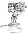
図1はインパクトドライバの側断面図であり、図示のインパクトドライバは、バッテリ1を電源とし、ブラシ付きモータ2を駆動源として回転打撃機構を駆動し、アンビル3に回転と打撃を与えることによって先端工具である不図示のビットに回転打撃力を間欠的に伝達してネジ締め等の作業を行うものである。
FIG. 1 is a side sectional view of an impact driver. The impact driver shown in FIG. 1 has a battery 1 as a power source and a brushed
上記ブラシ付きモータ3は、ハウジング4の胴体部4A内に収容されており、ハウジング4の胴体部4Aから下方に一体に延びるハンドル部4Bの上部には、前記バッテリ1からモータ2への給電をON/OFFしてモータ2を起動/停止させるためのトリガ5が設けられている。
The brushed
而して、ハンマケース6に内蔵された回転打撃機構においては、ブラシ付きモータ2の出力軸2aの回転は遊星ギヤ機構7を経て減速されてスピンドル8に伝達され、該スピンドル8が所定の速度で回転駆動される。
Thus, in the rotary striking mechanism built in the
上記スピンドル8は、その軸方向一端(後端)がベアリング9を介してギヤカバー10に回転可能に支持され、他端(前端)は前記アンビル3の中心部に回転可能に保持されている。又、アンビル3は、軸受メタル11を介してハンマケース6の前端部に回転可能に支持されている。
One end (rear end) in the axial direction of the
更に、スピンドル8の外周にはハンマ12が回転可能に支持されており、スピンドル8とハンマ12とはカム機構によって連結されておいる。ここで、カム機構は、スピンドル8の外周面に形成されたV字状のスピンドルカム溝8a及びハンマ12の内周面に形成されたV字状のハンマカム溝12a及びこれらのカム溝8a,12aに係合するボール13で構成されている。そして、ハンマ12は、スプリング14によって常に先端方向(図1の右方)に付勢されており、静止時にはボール13とカム溝8a,12aとの係合によってアンビル3の端面とは隙間を隔てた位置にある。尚、ハンマ12とアンビル3の相対向する回転平面上の2箇所には凸部12b,3aがそれぞれ対称的に形成されている。
Further, a
而して、前述のようにスピンドル8が回転駆動されると、その回転は前記カム機構を介してハンマ12に伝達され、ハンマ12が半回転しないうちに、該ハンマ12の凸部12bがアンビル3の凸部3aに係合してアンビル3を回転させるが、そのときの係合反力によってスピンドル8とハンマ12との間に相対回転が生ずると、ハンマ12はカム機構のスピンドルカム溝8aに沿ってスプリング14を圧縮しながらブラシ付きモータ2側へと後退を始める。
Thus, when the
そして、ハンマ12の後退動によって該ハンマ12の凸部12bがアンビル3の凸部3aを乗り越えて両者の係合が解除されると、ハンマ12は、スピンドル8の回転力に加え、スプリング14に蓄積されていた弾性エネルギーとカム機構の作用によって回転方向及び前方に急速に加速されつつ、スプリング14の付勢力によって前方へ移動し、その凸部12bがアンビル3の凸部3aに再び係合して一体に回転し始める。このとき、強力な回転打撃力がアンビル3に加えられるため、該アンビル3に装着された不図示のビットを介して不図示のネジに回転打撃力が伝達される。
When the
以後、同様の動作が繰り返されてビットからネジに回転打撃力が間欠的に繰り返し伝達され、該ネジが木材等の被締結材にねじ込まれる。 Thereafter, the same operation is repeated so that the rotational impact force is intermittently repeatedly transmitted from the bit to the screw, and the screw is screwed into the material to be fastened such as wood.
ところで、インパクトドライバにおいては、トリガ5を引き操作するとバッテリ1からブラシ付きモータ2に電力(電流)が供給されて該ブラシ付きモータ2が起動され、トリガ5から手を離すとバッテリ1からブラシ付きモータ2への電力(電流)の供給が遮断されて該ブラシ付きモータ2の駆動が停止される。そして、ブラシ付きモータ2の回転方向は後述の正逆切替スイッチ15(図2及び図3参照)によって切り替えられる。又、トリガ5の引き操作量に比例してブラシ付きモータ2の回転速度が調整される。
By the way, in the impact driver, when the
ここで、インパクトドライバの駆動回路とスイッチ装置の構造を図2及び図3に基づいて説明する。尚、図2はインパクトドライバの駆動回路図、図3はスイッチ装置の側断面図である。 Here, the drive circuit of the impact driver and the structure of the switch device will be described with reference to FIGS. 2 is a drive circuit diagram of the impact driver, and FIG. 3 is a side sectional view of the switch device.
図2において、1は充電可能な複数の2次電池を直列に接続して成る前記バッテリ、2はブラシ2bを備えた前記ブラシ付きモータであり、これらのバッテリ1とブラシ付きモータ2を接続して閉回路を構成する電流ラインには前記正逆切替スイッチ15と半導体スイッチとしてのFET(電界効果トランジスタ)16が設けられている。
In FIG. 2, 1 is the battery formed by connecting a plurality of rechargeable secondary batteries in series, 2 is the brush motor provided with a
又、電流ラインとは別ラインに、トリガ5のON/OFF動作に連動してON/OFFされるスイッチ17と抵抗Rを含むON/OFF状態回路18と、トリガ5の操作量に比例する信号を出力する可変抵抗VRを含むトリガ操作量状態回路19が設けられており、これらのON/OFF状態回路18とトリガ操作量状態回路19と前記正逆切替スイッチ15によってスイッチ装置20が構成されている。
In addition, a signal that is proportional to the amount of operation of the
更に、電流ラインとは別ラインには、前記バッテリ1の電圧(14.4V)を所定の電圧(5V)まで下げるレギュレータ21と、制御手段としてのマイコン(マイクロコンピュータ)22と、前記FET16を駆動するドライバ23が設けられており、これらのレギュレータ21、マイコン22、ドライバ23及び前記FET16はメイン基板24を構成している。
Further, on a line different from the current line, a
次に、スイッチ装置20の具体的な構成を図3に基づいて説明すると、該スイッチ装置20には引き操作するための前記トリガ5が図3の左右方向に移動可能に設けられており、該トリガ5のロッド5aにはON/OFF状態回路用セッペン25とトリガ引き量状態回路用セッペン26が設けられている。そして、トリガ5は、ロッド5aとスイッチケース27間に縮装されたリターンスプリング28によって図3の左方(OFF方向)に付勢されている。尚、図3において、15は正逆切替スイッチである。
Next, a specific configuration of the
而して、トリガ5が引き操作されていない図3に示す状態では、ON/OFF状態回路用セッペン25はメイン基板24に接触しておらず、スイッチ17は図2に実線にて示すようにOFF状態にあって、マイコン22は、ON/OFF状態回路18から送信される信号によってスイッチ17がOFF状態であることを検出し、ドライバ23によってFET16を動作させてバッテリ1からブラシ付モータ2への電力供給をOFFするため、バッテリ1からブラシ付きモータ2への電力(電流)の供給はなされず、該ブラシ付きモータ2は起動されない。
Thus, in the state shown in FIG. 3 in which the
作業者がトリガ5を図3の矢印方向に引き操作すれば、ON/OFF状態回路用セッペン25はメイン基板24に接触して図2に示すスイッチ17が破線にて示すようにONされ、抵抗Rを電流が流れるため、この抵抗R分だけ電圧が降下し、これによってマイコン22はスイッチ17がONされた状態を検出し、ドライバ23によってFET16を動作させてバッテリ1からブラシ付モータ2への電力供給をONするため、バッテリ1からブラシ付きモータ2への電力(電流)の供給がなされて該ブラシ付きモータ2が起動され、図1に示すインパクトドライバが前述のように動作してネジ締め作業がなされる。
When the operator pulls the
又、同時にトリガ5の引き操作によって図3に示すトリガ引き量状態状態回路用セッペン26がメイン基板24に沿って摺動し、図2に示すトリガ引き量状態回路19の可変抵抗VRの抵抗値がトリガ5の引き量に比例して変化すると、その抵抗値の変化に伴う電圧変化がマイコン22によって検出される。そして、マイコン22は、トリガ5の操作量に基づいてドライバ23によってFET16を動作させてバッテリ1からブラシ付きモータ2への電力供給量を制御し、トリガ5の操作量に比例してブラシ付きモータ2の回転速度を制御する。
At the same time, the trigger pull state
以上のように、本実施の形態に係るインパクトドライバにおいては、図2に示すように、電流ラインとは別ラインに設けられたON/OFF状態回路18によってトリガ5のON/OFF動作を検出し、その検出結果によってマイコン22がFET16を動作させてバッテリ1からブラシ付モータ2への電力供給をON/OFFするようにしたため、メカ接点が不要となり、接点劣化を無くしてスイッチ装置20の寿命を高めることができるとともに、リターンスプリング28の付勢力(バネ定数)を小さく抑えてトリガ5の操作荷重を軽くすることができ、長時間の作業によって作業者がトリガ5を引き操作を繰り返しても、作業者の疲労が軽減される。
As described above, in the impact driver according to the present embodiment, as shown in FIG. 2, the ON / OFF operation of the
又、本実施の形態では、電流ラインとは別ラインに設けられたトリガ操作量状態回路19によって検出されたトリガ5の操作量に基づいてマイコン22がFET16を動作させてバッテリ1からブラシ付きモータ2への電力供給量を制御するようにしたため、トリガ5の操作量に比例してブラシ付きモータ2の回転速度を制御することができる。
Further, in the present embodiment, the
尚、以上は本発明をインパクトドライバに適用した形態について説明したが、本発明は、バッテリを電源として動作するブラシ付きモータを駆動源とする他の任意の電動工具に対しても同様に適用可能であることは勿論である。 Although the present invention has been described with respect to an embodiment in which the present invention is applied to an impact driver, the present invention can be similarly applied to any other electric tool using a motor with a brush that operates using a battery as a power source. Of course.
1 バッテリ
2 ブラシ付きモータ
2a ブラシ付きモータの出力軸
2b ブラシ付きモータのブラシ
3 アンビル
3a アンビルの凸部
4 ハウジング
4A ハウジングの胴体部
4B ハウジングのハンドル部
5 トリガ
6 ハンマケース
7 遊星ギヤ機構
8 スピンドル
8a スピンドルカム溝
9 ベアリング
10 ギヤカバー(カバー部材)
11 軸受メタル
12 ハンマ
12a ハンマカム溝
12b ハンマの凸部
13 ボール
14 スプリング
15 正逆切替スイッチ
16 FET(半導体スイッチ)
17 スイッチ
18 ON/OFF状態回路
19 トリガ引き量状態回路
20 スイッチ装置
21 レギュレータ
22 マイコン(制御手段)
23 ドライバ
24 メイン基板
25 ON/OFF状態回路用セッペン
26 トリガ引き量状態回路用セッペン
27 スイッチケース
28 リターンスプリング
R 抵抗
VR 可変抵抗
DESCRIPTION OF SYMBOLS 1
DESCRIPTION OF SYMBOLS 11
17
23
Claims (2)
前記ブラシ付きモータと前記バッテリとを接続する電流ラインに半導体スイッチを設けるとともに、前記電流ラインとは別ラインに、前記トリガのON/OFF動作に連動してON/OFFされるスイッチを含むON/OFF状態回路と、該ON/OFF状態回路から送信されるON/OFF信号に基づいて前記半導体スイッチを動作させて前記バッテリから前記ブラシ付モータへの電力供給をON/OFFする制御手段を設けたことを特徴とする電動工具。 In a power tool comprising a brushed motor as a drive source, a battery for supplying power to the brushed motor, and a trigger for turning on / off power supply from the battery to the brushed motor,
A semiconductor switch is provided in a current line connecting the brushed motor and the battery, and an ON / OFF including a switch that is turned on / off in conjunction with the ON / OFF operation of the trigger is provided on a line different from the current line. An OFF state circuit and control means for operating the semiconductor switch based on an ON / OFF signal transmitted from the ON / OFF state circuit to turn on / off power supply from the battery to the brushed motor are provided. An electric tool characterized by that.
A trigger operation amount state circuit for transmitting a signal proportional to the operation amount of the trigger to the control means is provided on a line different from the current line, and the control means is based on a signal transmitted from the trigger operation amount state circuit. The power tool according to claim 1, wherein the power switch controls the amount of power supplied from the battery to the brushed motor by operating the semiconductor switch.
Priority Applications (1)
| Application Number | Priority Date | Filing Date | Title |
|---|---|---|---|
| JP2008031214A JP2009190099A (en) | 2008-02-13 | 2008-02-13 | Power tool |
Applications Claiming Priority (1)
| Application Number | Priority Date | Filing Date | Title |
|---|---|---|---|
| JP2008031214A JP2009190099A (en) | 2008-02-13 | 2008-02-13 | Power tool |
Publications (1)
| Publication Number | Publication Date |
|---|---|
| JP2009190099A true JP2009190099A (en) | 2009-08-27 |
Family
ID=41072596
Family Applications (1)
| Application Number | Title | Priority Date | Filing Date |
|---|---|---|---|
| JP2008031214A Withdrawn JP2009190099A (en) | 2008-02-13 | 2008-02-13 | Power tool |
Country Status (1)
| Country | Link |
|---|---|
| JP (1) | JP2009190099A (en) |
Cited By (5)
| Publication number | Priority date | Publication date | Assignee | Title |
|---|---|---|---|---|
| US8446120B2 (en) | 2011-05-19 | 2013-05-21 | Black & Decker Inc. | Electronic switching module for a power tool |
| JP2014048998A (en) * | 2012-09-03 | 2014-03-17 | Yahoo Japan Corp | Recommended commodity notification device, recommended commodity notification method, and recommended commodity notification program |
| CN106952763A (en) * | 2015-11-20 | 2017-07-14 | 美克司株式会社 | Possess for making the instrument of the switch of electrical equipment action |
| US10608501B2 (en) | 2017-05-24 | 2020-03-31 | Black & Decker Inc. | Variable-speed input unit having segmented pads for a power tool |
| US11154975B2 (en) | 2015-11-20 | 2021-10-26 | Max Co., Ltd. | Tool |
-
2008
- 2008-02-13 JP JP2008031214A patent/JP2009190099A/en not_active Withdrawn
Cited By (13)
| Publication number | Priority date | Publication date | Assignee | Title |
|---|---|---|---|---|
| US10256697B2 (en) | 2011-05-19 | 2019-04-09 | Black & Decker Inc. | Electronic switching module for a power tool |
| US9000882B2 (en) | 2011-05-19 | 2015-04-07 | Black & Decker Inc. | Electronic switching module for a power tool |
| US9401250B2 (en) | 2011-05-19 | 2016-07-26 | Black & Decker, Inc. | Electronic switching module for a power tool |
| US9406457B2 (en) | 2011-05-19 | 2016-08-02 | Black & Decker Inc. | Electronic switching module for a power tool |
| US9508498B2 (en) | 2011-05-19 | 2016-11-29 | Black & Decker, Inc. | Electronic switching module for a power tool |
| US8446120B2 (en) | 2011-05-19 | 2013-05-21 | Black & Decker Inc. | Electronic switching module for a power tool |
| US10651706B2 (en) | 2011-05-19 | 2020-05-12 | Black & Decker Inc. | Control unit for a power tool |
| JP2014048998A (en) * | 2012-09-03 | 2014-03-17 | Yahoo Japan Corp | Recommended commodity notification device, recommended commodity notification method, and recommended commodity notification program |
| CN106952763A (en) * | 2015-11-20 | 2017-07-14 | 美克司株式会社 | Possess for making the instrument of the switch of electrical equipment action |
| CN106952763B (en) * | 2015-11-20 | 2019-09-10 | 美克司株式会社 | Has the tool for making the switch of electrical equipment action |
| EP3208048A1 (en) * | 2015-11-20 | 2017-08-23 | Max Co., Ltd. | Tool |
| US11154975B2 (en) | 2015-11-20 | 2021-10-26 | Max Co., Ltd. | Tool |
| US10608501B2 (en) | 2017-05-24 | 2020-03-31 | Black & Decker Inc. | Variable-speed input unit having segmented pads for a power tool |
Similar Documents
| Publication | Publication Date | Title |
|---|---|---|
| JP5589255B2 (en) | Portable power tools | |
| US7543728B2 (en) | Hand-held drive-in tool | |
| US9737984B2 (en) | Power tool | |
| JP5824419B2 (en) | Electric tool | |
| JP5974616B2 (en) | Electric tool | |
| CN110270956B (en) | Screw fastening tool | |
| JP2009190099A (en) | Power tool | |
| JP5766843B2 (en) | Shift switch | |
| JP6004226B2 (en) | Trigger switch and power tool | |
| HK1131364A1 (en) | Electric power tool | |
| JP2006326828A (en) | Electric driving device | |
| US20120000755A1 (en) | Electric tool | |
| JP2015526301A (en) | Power tools and manual electrical equipment | |
| JP5536598B2 (en) | Shift switch | |
| JP5003223B2 (en) | Electric tool | |
| JP5574981B2 (en) | Electric tool | |
| JP2008183691A (en) | Power tool | |
| JP4986640B2 (en) | Constant torque electric screwdriver | |
| JP5472411B2 (en) | Electric tool | |
| GB2486564A (en) | Function control in an electric power hand tool | |
| JP6105446B2 (en) | Work tools | |
| JP2007021620A (en) | Power tool | |
| JP5088614B2 (en) | Electric tool | |
| JP5351555B2 (en) | Power tool switch | |
| JP4454674B2 (en) | Screw tightening device |
Legal Events
| Date | Code | Title | Description |
|---|---|---|---|
| A300 | Application deemed to be withdrawn because no request for examination was validly filed |
Free format text: JAPANESE INTERMEDIATE CODE: A300 Effective date: 20110510 |