EP3207362B1 - Plate-forme de détection de réactance et de capacité pour détecter des micro-organismes - Google Patents
Plate-forme de détection de réactance et de capacité pour détecter des micro-organismes Download PDFInfo
- Publication number
- EP3207362B1 EP3207362B1 EP15853221.8A EP15853221A EP3207362B1 EP 3207362 B1 EP3207362 B1 EP 3207362B1 EP 15853221 A EP15853221 A EP 15853221A EP 3207362 B1 EP3207362 B1 EP 3207362B1
- Authority
- EP
- European Patent Office
- Prior art keywords
- frequency
- khz
- electrodes
- switch
- electrical signal
- Prior art date
- Legal status (The legal status is an assumption and is not a legal conclusion. Google has not performed a legal analysis and makes no representation as to the accuracy of the status listed.)
- Active
Links
- 244000005700 microbiome Species 0.000 title description 25
- 239000000523 sample Substances 0.000 claims description 57
- 230000012010 growth Effects 0.000 claims description 42
- 230000000813 microbial effect Effects 0.000 claims description 31
- 238000000034 method Methods 0.000 claims description 25
- 230000035945 sensitivity Effects 0.000 claims description 16
- 239000003990 capacitor Substances 0.000 claims description 14
- 238000012545 processing Methods 0.000 claims description 5
- 239000012472 biological sample Substances 0.000 claims description 4
- 238000001514 detection method Methods 0.000 description 66
- 239000007788 liquid Substances 0.000 description 31
- 239000008280 blood Substances 0.000 description 17
- 210000004369 blood Anatomy 0.000 description 17
- 230000003287 optical effect Effects 0.000 description 15
- 238000005259 measurement Methods 0.000 description 14
- 241000588724 Escherichia coli Species 0.000 description 13
- 229910052751 metal Inorganic materials 0.000 description 13
- 239000002184 metal Substances 0.000 description 13
- 210000004027 cell Anatomy 0.000 description 12
- 230000008859 change Effects 0.000 description 12
- 239000002609 medium Substances 0.000 description 12
- 239000000203 mixture Substances 0.000 description 11
- 238000002474 experimental method Methods 0.000 description 10
- 230000006872 improvement Effects 0.000 description 9
- 238000000576 coating method Methods 0.000 description 8
- 238000012360 testing method Methods 0.000 description 8
- 241000894006 Bacteria Species 0.000 description 7
- 239000011248 coating agent Substances 0.000 description 7
- 239000006227 byproduct Substances 0.000 description 6
- 230000001419 dependent effect Effects 0.000 description 6
- 230000002503 metabolic effect Effects 0.000 description 6
- 230000001878 mycolytic effect Effects 0.000 description 6
- 230000004044 response Effects 0.000 description 6
- 238000001228 spectrum Methods 0.000 description 6
- 230000001413 cellular effect Effects 0.000 description 5
- 230000001332 colony forming effect Effects 0.000 description 5
- 229910052737 gold Inorganic materials 0.000 description 5
- 239000010931 gold Substances 0.000 description 5
- 150000002500 ions Chemical class 0.000 description 5
- 239000012528 membrane Substances 0.000 description 5
- 230000009467 reduction Effects 0.000 description 5
- 241001135518 Acinetobacter lwoffii Species 0.000 description 4
- 239000004593 Epoxy Substances 0.000 description 4
- 241000025769 Mucor luteus Species 0.000 description 4
- 238000013461 design Methods 0.000 description 4
- 230000000694 effects Effects 0.000 description 4
- PCHJSUWPFVWCPO-UHFFFAOYSA-N gold Chemical compound [Au] PCHJSUWPFVWCPO-UHFFFAOYSA-N 0.000 description 4
- 239000001963 growth medium Substances 0.000 description 4
- 230000002906 microbiologic effect Effects 0.000 description 4
- 230000005789 organism growth Effects 0.000 description 4
- 230000010076 replication Effects 0.000 description 4
- 239000002028 Biomass Substances 0.000 description 3
- 229910001369 Brass Inorganic materials 0.000 description 3
- 240000002355 Celtis tournefortii var. glabrata Species 0.000 description 3
- 241000606768 Haemophilus influenzae Species 0.000 description 3
- 230000001580 bacterial effect Effects 0.000 description 3
- 230000008901 benefit Effects 0.000 description 3
- 239000010951 brass Substances 0.000 description 3
- 239000011159 matrix material Substances 0.000 description 3
- 230000007246 mechanism Effects 0.000 description 3
- 238000012544 monitoring process Methods 0.000 description 3
- 239000004033 plastic Substances 0.000 description 3
- BASFCYQUMIYNBI-UHFFFAOYSA-N platinum Chemical compound [Pt] BASFCYQUMIYNBI-UHFFFAOYSA-N 0.000 description 3
- 229910052709 silver Inorganic materials 0.000 description 3
- 239000000126 substance Substances 0.000 description 3
- XEEYBQQBJWHFJM-UHFFFAOYSA-N Iron Chemical compound [Fe] XEEYBQQBJWHFJM-UHFFFAOYSA-N 0.000 description 2
- PXHVJJICTQNCMI-UHFFFAOYSA-N Nickel Chemical compound [Ni] PXHVJJICTQNCMI-UHFFFAOYSA-N 0.000 description 2
- BQCADISMDOOEFD-UHFFFAOYSA-N Silver Chemical compound [Ag] BQCADISMDOOEFD-UHFFFAOYSA-N 0.000 description 2
- 238000013019 agitation Methods 0.000 description 2
- 238000013459 approach Methods 0.000 description 2
- 238000009640 blood culture Methods 0.000 description 2
- 238000006243 chemical reaction Methods 0.000 description 2
- 150000001875 compounds Chemical class 0.000 description 2
- 238000007405 data analysis Methods 0.000 description 2
- 238000010586 diagram Methods 0.000 description 2
- 238000000157 electrochemical-induced impedance spectroscopy Methods 0.000 description 2
- 230000002708 enhancing effect Effects 0.000 description 2
- 239000012530 fluid Substances 0.000 description 2
- 230000006870 function Effects 0.000 description 2
- 239000012212 insulator Substances 0.000 description 2
- JVTAAEKCZFNVCJ-UHFFFAOYSA-N lactic acid Chemical compound CC(O)C(O)=O JVTAAEKCZFNVCJ-UHFFFAOYSA-N 0.000 description 2
- 239000000463 material Substances 0.000 description 2
- 238000007620 mathematical function Methods 0.000 description 2
- 239000002245 particle Substances 0.000 description 2
- 230000008569 process Effects 0.000 description 2
- 239000000047 product Substances 0.000 description 2
- 239000000376 reactant Substances 0.000 description 2
- 150000003839 salts Chemical class 0.000 description 2
- 238000005070 sampling Methods 0.000 description 2
- 239000004332 silver Substances 0.000 description 2
- 230000003595 spectral effect Effects 0.000 description 2
- RYGMFSIKBFXOCR-UHFFFAOYSA-N Copper Chemical compound [Cu] RYGMFSIKBFXOCR-UHFFFAOYSA-N 0.000 description 1
- 241000233866 Fungi Species 0.000 description 1
- 229910019142 PO4 Inorganic materials 0.000 description 1
- 206010036790 Productive cough Diseases 0.000 description 1
- 229910000831 Steel Inorganic materials 0.000 description 1
- 241000700605 Viruses Species 0.000 description 1
- HCHKCACWOHOZIP-UHFFFAOYSA-N Zinc Chemical compound [Zn] HCHKCACWOHOZIP-UHFFFAOYSA-N 0.000 description 1
- 238000009825 accumulation Methods 0.000 description 1
- 230000009471 action Effects 0.000 description 1
- 238000004026 adhesive bonding Methods 0.000 description 1
- 229910052782 aluminium Inorganic materials 0.000 description 1
- XAGFODPZIPBFFR-UHFFFAOYSA-N aluminium Chemical compound [Al] XAGFODPZIPBFFR-UHFFFAOYSA-N 0.000 description 1
- 150000001413 amino acids Chemical class 0.000 description 1
- 238000004458 analytical method Methods 0.000 description 1
- 238000009635 antibiotic susceptibility testing Methods 0.000 description 1
- 238000003556 assay Methods 0.000 description 1
- 244000052616 bacterial pathogen Species 0.000 description 1
- 230000015572 biosynthetic process Effects 0.000 description 1
- 238000000071 blow moulding Methods 0.000 description 1
- 238000004422 calculation algorithm Methods 0.000 description 1
- 238000004364 calculation method Methods 0.000 description 1
- 230000032823 cell division Effects 0.000 description 1
- 210000000170 cell membrane Anatomy 0.000 description 1
- 210000002421 cell wall Anatomy 0.000 description 1
- 210000003850 cellular structure Anatomy 0.000 description 1
- 239000004020 conductor Substances 0.000 description 1
- 239000000470 constituent Substances 0.000 description 1
- 239000000356 contaminant Substances 0.000 description 1
- 229910052802 copper Inorganic materials 0.000 description 1
- 239000010949 copper Substances 0.000 description 1
- 230000001186 cumulative effect Effects 0.000 description 1
- 230000003247 decreasing effect Effects 0.000 description 1
- 230000001066 destructive effect Effects 0.000 description 1
- 238000003745 diagnosis Methods 0.000 description 1
- 238000006073 displacement reaction Methods 0.000 description 1
- 238000009713 electroplating Methods 0.000 description 1
- 210000003013 erythroid precursor cell Anatomy 0.000 description 1
- 230000008020 evaporation Effects 0.000 description 1
- 238000001704 evaporation Methods 0.000 description 1
- 230000029142 excretion Effects 0.000 description 1
- 239000007789 gas Substances 0.000 description 1
- 239000003292 glue Substances 0.000 description 1
- 210000005260 human cell Anatomy 0.000 description 1
- 238000002847 impedance measurement Methods 0.000 description 1
- 230000036512 infertility Effects 0.000 description 1
- 230000010354 integration Effects 0.000 description 1
- 239000000543 intermediate Substances 0.000 description 1
- 229910052742 iron Inorganic materials 0.000 description 1
- 235000014655 lactic acid Nutrition 0.000 description 1
- 239000004310 lactic acid Substances 0.000 description 1
- 238000004519 manufacturing process Methods 0.000 description 1
- 238000000691 measurement method Methods 0.000 description 1
- 230000004060 metabolic process Effects 0.000 description 1
- 239000002207 metabolite Substances 0.000 description 1
- 238000001465 metallisation Methods 0.000 description 1
- 150000002739 metals Chemical class 0.000 description 1
- 238000002156 mixing Methods 0.000 description 1
- 238000012986 modification Methods 0.000 description 1
- 230000004048 modification Effects 0.000 description 1
- 238000000465 moulding Methods 0.000 description 1
- 230000007935 neutral effect Effects 0.000 description 1
- 229910052759 nickel Inorganic materials 0.000 description 1
- 150000002823 nitrates Chemical class 0.000 description 1
- 235000015097 nutrients Nutrition 0.000 description 1
- 244000052769 pathogen Species 0.000 description 1
- 230000000737 periodic effect Effects 0.000 description 1
- 235000021317 phosphate Nutrition 0.000 description 1
- 150000003013 phosphoric acid derivatives Chemical class 0.000 description 1
- 229910052697 platinum Inorganic materials 0.000 description 1
- 239000004417 polycarbonate Substances 0.000 description 1
- 229920000515 polycarbonate Polymers 0.000 description 1
- 238000012805 post-processing Methods 0.000 description 1
- 238000002360 preparation method Methods 0.000 description 1
- 102000004196 processed proteins & peptides Human genes 0.000 description 1
- 108090000765 processed proteins & peptides Proteins 0.000 description 1
- -1 protons Chemical class 0.000 description 1
- 230000003362 replicative effect Effects 0.000 description 1
- 239000011347 resin Substances 0.000 description 1
- 229920005989 resin Polymers 0.000 description 1
- 239000010944 silver (metal) Substances 0.000 description 1
- 150000003384 small molecules Chemical class 0.000 description 1
- 238000004544 sputter deposition Methods 0.000 description 1
- 210000003802 sputum Anatomy 0.000 description 1
- 208000024794 sputum Diseases 0.000 description 1
- 230000003068 static effect Effects 0.000 description 1
- 239000010959 steel Substances 0.000 description 1
- 150000003467 sulfuric acid derivatives Chemical class 0.000 description 1
- 238000012546 transfer Methods 0.000 description 1
- 210000002700 urine Anatomy 0.000 description 1
- 239000002699 waste material Substances 0.000 description 1
- XLYOFNOQVPJJNP-UHFFFAOYSA-N water Substances O XLYOFNOQVPJJNP-UHFFFAOYSA-N 0.000 description 1
- 229910052725 zinc Inorganic materials 0.000 description 1
- 239000011701 zinc Substances 0.000 description 1
Images


Classifications
-
- C—CHEMISTRY; METALLURGY
- C12—BIOCHEMISTRY; BEER; SPIRITS; WINE; VINEGAR; MICROBIOLOGY; ENZYMOLOGY; MUTATION OR GENETIC ENGINEERING
- C12M—APPARATUS FOR ENZYMOLOGY OR MICROBIOLOGY; APPARATUS FOR CULTURING MICROORGANISMS FOR PRODUCING BIOMASS, FOR GROWING CELLS OR FOR OBTAINING FERMENTATION OR METABOLIC PRODUCTS, i.e. BIOREACTORS OR FERMENTERS
- C12M41/00—Means for regulation, monitoring, measurement or control, e.g. flow regulation
- C12M41/30—Means for regulation, monitoring, measurement or control, e.g. flow regulation of concentration
- C12M41/36—Means for regulation, monitoring, measurement or control, e.g. flow regulation of concentration of biomass, e.g. colony counters or by turbidity measurements
-
- G—PHYSICS
- G01—MEASURING; TESTING
- G01N—INVESTIGATING OR ANALYSING MATERIALS BY DETERMINING THEIR CHEMICAL OR PHYSICAL PROPERTIES
- G01N27/00—Investigating or analysing materials by the use of electric, electrochemical, or magnetic means
- G01N27/02—Investigating or analysing materials by the use of electric, electrochemical, or magnetic means by investigating impedance
-
- C—CHEMISTRY; METALLURGY
- C12—BIOCHEMISTRY; BEER; SPIRITS; WINE; VINEGAR; MICROBIOLOGY; ENZYMOLOGY; MUTATION OR GENETIC ENGINEERING
- C12Q—MEASURING OR TESTING PROCESSES INVOLVING ENZYMES, NUCLEIC ACIDS OR MICROORGANISMS; COMPOSITIONS OR TEST PAPERS THEREFOR; PROCESSES OF PREPARING SUCH COMPOSITIONS; CONDITION-RESPONSIVE CONTROL IN MICROBIOLOGICAL OR ENZYMOLOGICAL PROCESSES
- C12Q1/00—Measuring or testing processes involving enzymes, nucleic acids or microorganisms; Compositions therefor; Processes of preparing such compositions
- C12Q1/02—Measuring or testing processes involving enzymes, nucleic acids or microorganisms; Compositions therefor; Processes of preparing such compositions involving viable microorganisms
- C12Q1/04—Determining presence or kind of microorganism; Use of selective media for testing antibiotics or bacteriocides; Compositions containing a chemical indicator therefor
-
- G—PHYSICS
- G01—MEASURING; TESTING
- G01N—INVESTIGATING OR ANALYSING MATERIALS BY DETERMINING THEIR CHEMICAL OR PHYSICAL PROPERTIES
- G01N27/00—Investigating or analysing materials by the use of electric, electrochemical, or magnetic means
- G01N27/02—Investigating or analysing materials by the use of electric, electrochemical, or magnetic means by investigating impedance
- G01N27/026—Dielectric impedance spectroscopy
-
- G—PHYSICS
- G01—MEASURING; TESTING
- G01N—INVESTIGATING OR ANALYSING MATERIALS BY DETERMINING THEIR CHEMICAL OR PHYSICAL PROPERTIES
- G01N27/00—Investigating or analysing materials by the use of electric, electrochemical, or magnetic means
- G01N27/02—Investigating or analysing materials by the use of electric, electrochemical, or magnetic means by investigating impedance
- G01N27/04—Investigating or analysing materials by the use of electric, electrochemical, or magnetic means by investigating impedance by investigating resistance
-
- G—PHYSICS
- G01—MEASURING; TESTING
- G01N—INVESTIGATING OR ANALYSING MATERIALS BY DETERMINING THEIR CHEMICAL OR PHYSICAL PROPERTIES
- G01N33/00—Investigating or analysing materials by specific methods not covered by groups G01N1/00 - G01N31/00
- G01N33/48—Biological material, e.g. blood, urine; Haemocytometers
- G01N33/483—Physical analysis of biological material
- G01N33/487—Physical analysis of biological material of liquid biological material
- G01N33/48785—Electrical and electronic details of measuring devices for physical analysis of liquid biological material not specific to a particular test method, e.g. user interface or power supply
-
- G—PHYSICS
- G01—MEASURING; TESTING
- G01N—INVESTIGATING OR ANALYSING MATERIALS BY DETERMINING THEIR CHEMICAL OR PHYSICAL PROPERTIES
- G01N33/00—Investigating or analysing materials by specific methods not covered by groups G01N1/00 - G01N31/00
- G01N33/48—Biological material, e.g. blood, urine; Haemocytometers
- G01N33/483—Physical analysis of biological material
- G01N33/487—Physical analysis of biological material of liquid biological material
- G01N33/49—Blood
Definitions
- the present invention relates to the field of microbial detection in clinical samples.
- the invention is in particular related to achieving faster detection of the presence or absence of bacteria in a biological sample.
- indirect detection methods may estimate the effects of by-products, molecules, compounds, or chemical reactants on organism growth/replication. That is, whether the by-products, molecules, compounds, or chemical reactants collectively and cumulatively increase, decrease, or become altered as a result of organism growth/replication. For instance, the changing metabolic demands of a growing microorganism population may be observed through a change in fluorescence or through a colorimetric change of an elastomeric sensor. While such detection mechanisms are well-known, the detection threshold is exceeded when organism concentrations reach approximately 10 9 colony forming units (CFU) per bottle. This results in typical time-to-detection (TTD) in the range of 8 to 24 hours for many clinically relevant blood stream pathogens. In some cases, certain organisms may require more than 72 hours for detection.
- TTD time-to-detection
- the total ionic makeup of the sample is altered when microbial growth occurs.
- Microbial growth affects the overall conductivity (or resistivity) of the medium. This change in conduction (or resistance) manifests itself by changes in the overall electrical impedance of the solution over time. Impedance is measured by immersing a plurality of electrodes into the solution and measuring either the voltage (e.g., AC or DC) and/or current response.
- some well-known systems use a 10 mL reaction cell filled with a specialized broth.
- the reaction cell is inoculated with industrial microbiological samples and incubated for up to 24 hrs.
- a fixed frequency (10 kHz) input waveform is supplied into the tube and the impedance is monitored.
- the ionic composition of the medium changes in response to microbial growth over time, small changes in media conduction begin to accumulate.
- the conductivity has increased above a specified threshold, an indication of a sample testing positive for microbial growth is returned.
- systems of these types have major technical limitations such that the scope of their application has been limited mainly to industrial microbiological applications.
- electrical detection systems suffer from a technical limitation in that they rely on a conduction or resistance change in the growth medium due to formation and accumulation of by-products of microbial growth. Consequently, for high-ionic strength mediums, any signal generated by microbial replication is essentially masked until a very high concentration of microorganisms is present. Additionally, many applications that monitor a highly complex medium (e.g., blood) for microorganism growth and detection cannot use standard impedance based detection techniques.
- a highly complex medium e.g., blood
- Sengupta et. al. "A micro-scale multi-frequency reactance measurement technique to detect bacterial growth at low bio-particle concentrations," Lab Chip, Vol. 6, pp. 682-692 (2006 ) (hereinafter "Sengupta")
- a microfluidic chamber of 100 ⁇ L volume was used as a chamber that was monitored for a response that would indicate the presence of bacteria. Sengupta et. al.
- the sensing response can be improved relative to a simple dielectric conductivity measurement by providing a long (cm scale) and very thin ( ⁇ 250 microns) channel-like chamber containing the sample, with very small electrodes positioned at both ends.
- very high frequencies from 100 kHz to 100 MHz
- the capacitance contribution of the liquid sample was measured.
- the capacitance in the liquid sample is sensitive to changes caused by the presence and/or growth of bacteria in the sample disposed in the chamber.
- Sengupta states that temperature fluctuations were the most significant challenge to the use of the method of using a microfluidic environment to assay for the presence of bacteria in a sample using a dielectric conductivity measurement. Additionally, Sengupta obtains and measures a new sample for each analytical time point. That is, Sengupta requires filling a new microfluidics chamber (or replacing the liquid sample in the microfluidics chamber with fresh sample) before making a subsequent measurement. This approach is destructive as it requires consumption of approximately 100-200 ⁇ L of sample per hour, as each previously sampled portion is discarded. The volume of sample consumption over time could present a serious challenge, especially for samples with slow growing or slow metabolism microorganisms. Additionally, obtaining samples over time has inherent biohazard waste disposal and sterility concerns.
- Sengupta Another disadvantage of the technique described in Sengupta is the need to perform the experiment on the microliter volume scale. This prohibits the technique from sensing clinically relevant samples without the proper preparation or sub-sampling steps. Furthermore, the technique utilizes raw spectrum data from a wide range of frequencies (hundreds to thousands of kHz) to computationally fit to a circuit model of the "capacitance" of the solution. Thus, there is mathematical complexity surrounding the analysis of the data, which may result in up to a minute of post-processing time per consumable.
- Sengupta does not overcome the inherent incompatibility of high ionic media (e.g., blood) with the described impedance technique. Instead, Sengupta circumvents the problem by limiting the total number of ions by reducing the overall volume of the detection chamber. Therefore, even slightly higher volumes result in a large loss in sensitivity.
- high ionic media e.g., blood
- an impedance-based microbial growth detection method uses a sub-component, i.e. the imaginary (reactance) component, of the total impedance to determine the total ionic composition of the medium.
- the reactance sub-component has much higher sensitivity to both the change in ionic components of the media due to microorganism growth (indirect detection) and the charged cellular mass of the microorganisms (direct detection). This provides a broad detection approach for dealing with a wide and diverse spectrum of microorganisms.
- the frequency sensitivity of the system may be changed from 1 kHz to hundreds of kHz by tuning the physical value of resistors in parallel to a capacitive input stage of a lock-in amplifier detector. This results in an increased sensitivity towards changes in ionic composition (for operating frequencies between 1-20 kHz) and microbial biomass (for operation frequencies much greater than 20kHz) .
- a method for tuning the frequency sensitivity of the target sample through the use of a bridge resistor-capacitor tuning circuit is also described.
- the detection becomes sensitive to both changes in ionic composition and the charged organism mass in the high frequency spectrum (>> 20 kHz).
- the bridge resistor-capacitor tuning circuit yields faster time-to-detections (TTDs) .
- tuning the frequency response within the test consumable allows for the detection of microbial growth in relatively large volumes (e.g. >10 mL) of sample. This eliminates the prior art need to constantly sub-sample. Additional benefits are realized by utilizing the raw reactance data since complex mathematical calculations may no longer be required after each sample. The reduced computational complexity coupled to the utilization of a narrower range of frequencies allows for faster scan times (milliseconds to seconds versus seconds to minutes).
- the system includes signal processing electronic circuit connected to a test cell (i.e., consumable) through two or more electrodes that fully penetrate the test cell and are in contact with the fluid contents.
- the electronic circuit is configured to detect a component of the total impedance, specifically the "out-of-phase" or imaginary reactance component, which has a sensitive response to organism growth in a frequency-dependent manner.
- the reactance component of impedance is well-known to one skilled in the art and is not described in detail herein.
- the system may detect changes in both the composition of charged molecules in the liquid matrix and the number of microorganisms based on monitoring the sample for change in this parameter. This results in a 5-70% reduction in time-to-detection (TTD).
- TTD time-to-detection
- Electrodes should be fully immersed in a continuous body of liquid sample.
- the distance between electrodes may be adjusted or tuned to fit the needs of the consumable.
- the voltage inputs can also be adjusted to allow proper detection of the contents within the consumable.
- the current system is capable of sensing microorganisms present in what would otherwise be deemed “dirty" samples due to the highly charged nature of microorganism cell walls and their respective changes in the ionic composition of the liquid matrix. That is, the current system may monitor growth in an antimicrobial susceptibility test situation with blood contaminants and other constituents of the sample that would otherwise disrupt optical detection strategies.
- the presence or absence of microbial growth is determined using an impedance sub-component measurement.
- the electrode configuration and the frequency may be configured as described herein to ensure that even small changes in the ionic charge of the test environment are detectable to determine the presence or absence of microbial growth.
- Impedance is a measurement of the electrical opposition that a circuit presents to a current when a voltage is applied.
- impedance is an electrical characteristic of a substance that is comprised of two sub-components, resistance and reactance.
- Resistance is the opposition to the passage of an electrical current through an electrical conductor (e.g., metal wire, salt water solution, etc.). Resistance is a scalar value and is not frequency dependent. Accordingly, resistance has an inverse relationship with the total number of static (non-evolving) charged species (i.e., ions, protons, amino acids, peptides, small molecules, etc.) that are contained within a given sample. An increase in charged species results in a lower resistance while, conversely, a decrease results in a higher resistance. During microbial replication (commonly referred to as microbial growth), the total number of charged particles will continue to change in an organism-dependent manner.
- an electrical conductor e.g., metal wire, salt water solution, etc.
- ions are taken from the media and incorporated into the daughter cells.
- cell division results in a decreased number of charged species.
- organisms metabolize nutrients in the medium and produce charged products that result in an increase in the number of charged species.
- Reactance is the opposition of a circuit element to a change of electric current or voltage, due to that element's inductance or capacitance. Reactance is similar to electrical resistance, but differs in that reactance is sensitive to operating frequency. Accordingly, reactance has an inverse relationship with the total number of capacitive components that are contained within a given sample. In this regard, capacitance within biological samples is manifested in two ways. First, charged species (typically molecules, non-microbial cells, etc.) accumulate at the site of the electrode interface due to the application of a sensing voltage (or potential).
- charged species typically molecules, non-microbial cells, etc.
- Interface capacitance is greatest when the system is operating at low frequencies ( ⁇ 15 kHz). With respect to detecting microbial growth, the interface capacitance changes when there are changes in ionic composition of the medium due to increases in microbial cell mass and associated metabolites. As such, interface capacitance is an indirect indicator of microorganism growth.
- the other biological contributor to reactance is the capacitance of the cell.
- human and non-human cells have charged outer cell membranes, followed by an insulating membrane core, and finally highly ionic inner cell components (e.g. ions).
- highly ionic inner cell components e.g. ions.
- This is similar to the interface capacitance discussed above and shall be referred to as cellular capacitance or membrane capacitance (Cm).
- conductivity is a measurement related to the presence or absence of metabolic bacterial byproducts (e.g., gases, such as CO 2 ).
- metabolic bacterial byproducts e.g., gases, such as CO 2
- the capacitive components (and the changes in those components over time) discussed above more directly reflect the presence or absence of microorganisms (e.g., bacteria) in a sample container.
- the method and system described herein detects interface capacitance (Ci) and cellular capacitance (Cm) as manifested by changes in electrical reactance through the use of an external frequency tuning circuit.
- the external frequency tuning circuit is compatible with a plurality of media volumes ranging from a microliter to more than a milliliter. Furthermore, the external frequency tuning circuit allows for continuous monitoring without requiring periodic sub-sampling and refreshing of the sample being used.
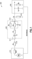
- FIG. 1 is a detailed illustration showing an apparatus for detecting microbial growth based on a measurement of the capacitive impedance of the component.
- a lock-in amplifier is shown having an output stage 210 and an input stage 235.
- the output stage 210 includes an internal signal generator that may be used to feed a sinusoidal RF signal to one electrode 211 of a dielectric impedance measuring chamber 220 (not shown).
- the second electrode 212 of said chamber is connected with the signal input stage 235 of said lock-in amplifier.
- a lock-in amplifier is shown in the figures and described in the examples herein, one of ordinary skill in the art would recognize that other measuring devices, such as an LCR meter or a network analyzer, may be used in place of the lock-in amplifier.
- the sample liquid within said chamber 220 (not shown) is in direct contact with the two electrodes and can be described by the circuit diagram shown in the dashed box 225.
- Ci represents the interface capacitance between the metal electrodes and the liquid
- Ri represents the interface resistance between the metal electrodes and the liquid
- Rb is the bulk resistance of the liquid
- Rm is the membrane resistance of the microorganisms
- Cm is the membrane capacitance.
- internal signal generator in the output stage 210 of the lock-in amplifier has a typical internal resistance of 50 Q
- lock-in amplifier input stage 235 has a typical capacitance (Cp) of 15 pF and a typical input resistance (Rp) of 10 M ⁇ .
- the apparatus for detecting microbial growth shown in FIG. 1 includes a source-matching resistor Rs (215) and a measuring load resistor Rv (216).
- the source-matching resistor 215 and the measuring load resister 216 may be selected for a given dielectric measuring chamber and liquid, such that the frequency spectrum of the out-of-phase component of the measurement signal shows a zero-crossing feature that (i) is dependent on the value of Cm, and (ii) is set at a conveniently low frequency. In certain examples that frequency is set at a value at or below about 100 kHz. This allows for the use of standard lock-in amplifiers.
- the out-of-phase signal amplitude with the output stage 210 of the lock-in amplifier is inversely proportional to the out-of-phase impedance value.
- the out-of phase impedance value e.g., the reactance value
- the lock-in amplifier input stage 235 provides reference potential.
- the reference as illustrated is a floating ground.
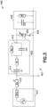
- FIG. 2 illustrates an alternate example, not part of the present invention, of an apparatus for measuring the dielectric capacitance and reactance of a liquid sample to determine changes in the ionic charge of the test environment using an automatic tuning of the measurement frequency.
- the out-of-phase signal output 332 of a phase-sensitive signal detector 330 is connected to the input 335 of an electronic integrator 340.
- the output 345 of the integrator 340 is connected to the frequency-control input 305 of a voltage-controlled oscillator 310 that acts as the signal generator as in the apparatus shown in FIG. 1 .
- Ci represents the interface capacitance between the metal electrodes and the liquid
- Ri represents the interface resistance between the metal electrodes and the liquid
- Rb is the bulk resistance of the liquid
- Cm is the bulk capacitance.
- bulk capacitance (Cb) as discussed in WO 2013/123189 .
- a sinusoidal electrical signal is generated by a voltage-controlled oscillator (“VCO") 310 and electrically coupled to an electrode 311 in contact with the sample.
- a second electrode 312, also in contact with the sample, is electrically connected to a phase-sensitive signal detector 330.
- the out-of-phase output signal of the phase-sensitive signal detector is coupled to the integrator 340. Because the output of the integrator 340 is coupled to the frequency-control input of the VCO 310, the frequency of the VCO 310 is adjusted until the out-of-phase signal amplitude measured by the phase-sensitive signal detector is at zero. Over time, an increase in the tuned frequency at zero out-of-phase signal amplitude indicates microorganism growth within the sample.
- the integrator 340 output voltage affects the frequency of the voltage-controlled oscillator. For example, if the starting frequency is below 60 kHz, the out-of-phase signal amplitude is positive. This leads to a positive output voltage at the integrator output 345 and, consequently, to an increase in the frequency of the voltage-controlled oscillator 310. The increase in frequency will continue until the zero-crossing frequency is reached (where the out-of-phase-signal amplitude is zero). At this moment, when the out-of-phase amplitude becomes zero, no further integration occurs. Thus, the frequency of the voltage-controlled oscillator is left at the zero-crossing frequency, which is 60.723 kHz according to this example. If the initial frequency is too high, the actual zero-crossing frequency would be automatically approached from the too high frequency. The presence of bacteria could be detected by recording the zero-crossing frequency over time and detecting an increase in frequency attributable to microbial growth.
- the advantage of the apparatus illustrated in FIG. 2 is that a zero-crossing frequency can be determined with extremely high precision. Due to the fact that a "Zero Signal" is generated at the output of the phase-sensitive signal detector, any drift in the signal generator amplitude or in the internal gain of the phase-sensitive signal detector will not affect the automatically tuned zero-crossing frequency, which represents the system output information.
- FIG. 3 an implementation of a system 400, part of the present invention, for measuring impedance using a bridge resistor (Rp)-capacitor tuning circuit 405 is shown.
- the system of FIG. 3 includes a output stage 410 of a lock-in amplifier with an internal signal generator, a variable series tunable element 415 (i.e. a variable potentiometer), a consumable 420 containing a liquid sample, a bridge resistor-capacitor tuning circuit (e.g., a second variable potentiometer 405 and a switch 425 wired in series), and an input stage 435 of the lock-in amplifier.
- a variable series tunable element 415 i.e. a variable potentiometer
- a consumable 420 containing a liquid sample
- a bridge resistor-capacitor tuning circuit e.g., a second variable potentiometer 405 and a switch 425 wired in series
- an input stage 435 of the lock-in amplifier when the switch
- the lock-in amplifier with an internal signal generator has a typical internal resistance of 50 ⁇ .
- the lock-in amplifier input stage 435 has a typical capacitance (Cis) of 15 pF and a typical input resistance (Ris) of 10 M ⁇ .
- the lock-in amplifier may generate the voltage and frequency applied to the liquid sample.
- measuring devices such as an LCR meter or a network analyzer, may be used without departing from the scope of the examples described herein.
- variable bridge tunable element (Rs) e.g., a variable potentiometer
- the variable bridge tunable element (Rs) 405 may be tuned to a resistance (0-10,000 ⁇ ) for a given consumable 420 (i.e., measuring chamber) and sample liquid, such that the frequency spectrum of the out-of-phase component of the measurement signal shows a zero-crossing feature that (i) is dependent on the value of Cm, and (ii) is positioned at a conveniently low frequency below 100 kHz. This allows for the use of standard lock-in amplifiers.
- the consumable 420 is largely a matter of design choice.
- the consumable is a plastic bottle or similar plastic consumable (not shown) with two apertures on the side spaced apart between about 10 mm to about 40 mm.
- a metalized electrode e.g., a brass cylinder piece electroplated with gold
- epoxy e.g., glue
- the consumable may have variety of geometries and adapter ports for sterile transfer of sample into and out of said consumable.
- different consumables may be used based on the patient specimen types, volumes of samples to be tested, etc.
- the metalized electrodes 411, 412 may be made of any standard (i.e., low-cost) metal (e.g., copper, brass, steel, etc.) that has a conformal coating (i.e., sub-nm to micron thickness) with a non-corroding metal (e.g., platinum, gold, silver) applied thereto.
- a conformal coating i.e., sub-nm to micron thickness
- a non-corroding metal e.g., platinum, gold, silver
- This conformal coating of a non-corroding metal is necessary to be compatible with high salt growth/media matrices (e.g. blood, urine, sputum).
- conformal coating techniques include electroplating, sputtering, and evaporation processes. Such processes are well known to one skilled in the art and not described in detail herein.
- One of ordinary skill in the art would select among convention conformal coating techniques to form the electrodes described herein.
- the electrode configuration may be adapted to virtually any size, geometry, and material used in a consumable (i.e., test device).
- the electrodes (2 or more) may be configured into any consumable format that has been provided with appropriate sized features to receive the electrodes.
- the consumable may be formed by blow molding the consumable around the electrodes.
- the electrodes may extend into the consumable through the cap of the consumable. This design does not require molding or gluing the electrodes directly into the material of the consumable.
- the electrodes may be configured to form a conduction path between the outside world and inner contents (i.e., liquid) of the consumable.
- consumables include traditional vials, tube configurations, microfluidic cartridges, etc. Suitable consumables are well-known to one skilled in the art and are not described in detail herein.
- suitable metals for the electrode include, but are not limited to, silver, gold, zinc, iron, nickel, aluminum, etc.
- different metal coatings could be used for the electrodes.
- the electrode spacing, trace wire configurations, and electrode dimensions are largely a matter of design choice. The electrode design depends on a variety of factors, such as the medium, the consumable, the sample, etc. One of ordinary skill in the art would recognize that a variety of configurations may be used based on the examples described herein.
- the electrodes In operation in those embodiments where the electrodes are positioned inside the consumable, the electrodes must be immersed within the sample liquid such that there is a conduction path between the electrodes. In other words, the same body of liquid that covers one electrode must also cover the other. Furthermore, the presence of non-biological objects within the bottle (e.g., epoxy, resin) must not cover the electrodes to an extent that may disturb the conductive path between electrodes resulting in highly variable and unreliable data.
- non-biological objects within the bottle e.g., epoxy, resin
- the system is configured to receive the consumable (schematically illustrated in FIG. 3 ) such that it will be integrated electronically into the system 400.
- an asymmetric feature may be formed into the consumable such that the user can only insert the consumable into the instrument in one pre-determined orientation. This will ensure proper interconnection between the consumable "module" and the other components in the system.
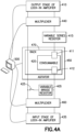
- FIGS. 4A and 4B various implementations of system 400 are shown for measuring impedance in multiple consumables.
- the system of FIGS. 4A and 4B include an output stage 410 of a lock-in amplifier, a multiplexer 440, a variable series resistor 415, a consumable 420 with a first electrode 411 and a second electrode 412, an agitator 450, a rack 470, a variable bridge resistor 405, a second multiplexer 460, an input stage 435 of the lock-in amplifier, and a computer 500.
- the switch 425 is in series with the variable bridge resistor 405. Such relationship between the switch 425 and bridge resistor 405 is also illustrated in FIG. 3 .
- FIG. 4B is an alternate configuration where switch 425 is parallel to variable bridge resistor 405.
- the consumables 420 may be stored in a rack-based modular platform 470.
- Each rack 470 may include multiplexer elements that can address up to 20 consumables.
- DSP digital signal processing
- the multiplexer circuitry 440 and 460 may allow a computer (e.g. 500), single detection board or instrument to scan a plurality of consumables or sub-components of a single consumable. In those embodiments where one consumable has multiple chambers with sample in each of the multiple chambers, the multiplexers act to "switch" the connection (1+ input and 1+ output) of the detection instrument/circuit to a single consumable or sub-component of a consumable.
- the multiplexer circuitry would allow for relatively few hardware components to monitor a plurality of consumables.
- the multiplexer circuitry may have a number of operating variations, depending upon the extent of multiplexing and consumable configurations.
- measurements of the consumables may be done serially. That is, each consumable in the array may be scanned one at a time. The scan time per consumable may be on the order of tens of seconds. Therefore, each rack (if completely full) will take roughly 2-3 minutes to scan.
- the computing device 500 may repeat the scanning action every 10-15 minutes.
- it may agitate the consumables using the agitator 450 to fully mix and aerate the liquid. Agitation may be performed through vertical displacement, orbital shaking, or through the use of stir-bars within the consumable.
- the agitation mechanism (if required) may have a variety of configurations including horizontal shaking mechanisms to maximize sample mixing.
- agitators may be used from the examples described herein and are therefore not discussed in greater detail.
- the variable bridge resistor 405 may be an external tuning circuit that physically connects the consumable 420 to the detection instrument (i.e. the input stage 435 of the lock-in amplifier).
- the variable bridge resistor 405 may contain a series of parallel variable resistors (digital potentiometers) that allow for "on-the-fly frequency tuning and calibration" of the frequency sensitivity.
- the frequency of the signal from the consumable may be tuned to between about 1 kHz and about 200 MHz.
- the tuning parameters i.e., frequency range selected and peak-to-peak voltage
- the system is able to detect metabolic by-products at low frequencies and organism biomass at higher frequencies independently.
- a switch 425 may be wired in series with the series of variable bridge resistor 405 as shown in FIG. 4A .
- the switch 425 may be wired in parallel with the variable bridge resistor 405 as shown in FIG. 4B .
- the switch When the switch is open, the system may operate at a low frequency (i.e., 1 to 20 kHz). As noted above, this will enable detection of changes in the make-up of the consumable.
- the switch When the switch is closed, the system may operate at higher frequencies (i.e., >> 20 kHz) by providing feedback to the signal generator.
- the system becomes sensitive to both changes in ionic composition of the liquid and the organism mass itself. By having the ability to tune the frequency to test at both high and low frequencies, the system may yield faster time-to-detections (TTDs) with lower volumes of sample.
- TTDs time-to-detections
- using subcomponents of the signals may 1) allow for continuous monitoring of each consumable or subcomponent of a consumable at specified intervals (e.g. about 10 minutes) for several days (e.g. 5 day protocol) and 2) detect changes in the composition of charged molecules and number of biological cells or components of the sample.
- a data analysis may be performed once the signals are input into the input stage 435 of the lock-in amplifier.
- the data analysis is performed in two steps to determine microbial growth.
- raw spectral data i.e., detected reactance signal vs. frequency
- a generalized algorithm is applied to determine at which point a statistically significant deviation from known control values indicates the presence of an organism. Due to the enhanced sensitivity to microbial growth, the examples described herein provide faster detection times of microbial growth.
- a single extracted data value from the raw "reactance" data may be used to determine the presence or absence of microbial growth.
- the extracted data may use mathematical functions to determine intercepts or areas under a curve. The results of these mathematical functions may be compared to threshold values. Thus, cumulative changes above threshold values may be used to differentiate between organism-containing consumables.
- the frequency spectrum of the out-of-phase component of the measurement signal shows a zero-crossing feature that (i) is dependent on the value of Cm, and (ii) is set at a conveniently low frequency. The frequency is set at a value at or below about 100 kHz This allows for the use of standard measuring devices, such as the lock-in amplifiers described herein, LCR meters, and/or network analyzers.
- TTD time-to-detection
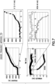
- FIG. 5 an experiment was conducted with a smaller polycarbonate tube that contained: 10 mL of BACTEC TM standard aerobic medium, 3 mL of bagged blood, 17 CFU (colony forming units) of E. coli organisms (A25922), and Au-plated metal electrodes (brass body) extending into the interior of the consumable and immersed in the medium/sample mixture.
- the electrodes in the consumable were interconnected with the other components of the lock-in amplifier.
- the bridge resistor setup for the instrument was set to 187 Ohms, resulting in a spectral sensitivity in the 40 to 80 kHz band.
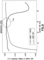
- TTDs When compared to controls (no organism) tube, which were scanned in parallel, TTDs improved significantly for most organisms and media as illustrated in FIG. 6 . This may indicate organism sensitivity on the order of 10 4 -10 5 CFU, which is at least 2 to 4 orders of magnitude more sensitive than current optical measuring systems, which detect organism at approximately 10 9 CFU. These results represent a 70% reduction in time to detection as discussed in greater detail below with respect to FIG. 5 Detection at these levels has never been reported and was completely unexpected. For illustration, the frequency changes over time are shown for E . coli (vs. control). At low frequency, TTD was approximately 10hours, which is up to 5-10% faster. At high frequency, the TTD was improved to approximately 4 hours, which is almost 70% faster.
- FIG. 6 illustrates results of performing the experiment with 7 mL of bagged blood and 17 CFU of E. coli organisms (A25922); 7 mL of bagged blood and 17 CFU of S. aureus (A25923); 7 mL of bagged blood and 17 CFU of H. influenzae (A19418); 7 mL of bagged blood and 17 CFU of H. faecalis (A29212); and 7 mL of bagged blood and 17 CFU of C . glabrata (A66032).
- the E. coli growth was detected in approximately 8.5 to 9 hours, which is an improvement in TTD when compared to standard optical detection techniques for detecting the growth of E. coli in mycolytic media (10-11 hours).
- the S. aureus growth in mycolytic media was detected in about 10 hours which represented a 23% improvement over standard optical detection techniques.
- H. influenzae colony growth in mycolytic media was detected in approximately 16 hours. This represented a 16% improvement over the TTD for H. influenzae (16 hours) using standard optical detection techniques.
- the TTD was 11 hours, representing an 8% improvement over a TTD of 11-12 hours using standard optical detection techniques.
- the TTD for C is an improvement in TTD when compared to standard optical detection techniques for detecting the growth of E. coli in mycolytic media (10-11 hours).
- the S. aureus growth in mycolytic media was detected in about 10 hours which represented a 23% improvement over standard optical detection techniques.
- H. influenzae colony growth in mycolytic media was detected in approximately 16 hours. This represented
- glabrata colonies in mycolytic media was detected in approximately 17 hours, which represented a 45% improvement in TTD for C . glabrata (20-42 hours) using standard optical detection techniques. Improvement in TTD for this sample in standard aerobic media over standard optical techniques is also reported in FIGS. 5 and 6 .
- FIG. 7 illustrates that the improved time to detection achieved for the smaller volumes described above is also achieved for larger volumes of sample/media.
- 40 ml of standard BACTEC media and 10 ml of blood were combined in a BACTEC bottle.
- the sample was spotted with 50-60 CFU E. coli.
- TTD was 10.5-11 hours, which is up to 5% faster.
- the TTD was improved to 9.5-10 hours, which is up to 14% faster.
- FIG. 5 illustrates the time-to-detection of E. coli at different frequencies. All consumables were prepared the same way and the only difference was the presence or absence of organisms and the electrical parameters of the external circuit. In this regard, the experiment was performed with four 16 mL consumables, each prepared with 10 mL of standard aerobic medium and 3 mL of blood. Two of the consumables also had 17 colony forming units of the E. coli added (one for low frequency mode and one for high frequency mode). The electrodes of the consumable were 30 mm gold electrodes. During the experiment, a 500 mV peak-to-peak voltage was applied to the consumable and the consumable was agitated via shaking at a rate of 120 rotations per minute.
- variable bridge resistor e.g., 405 in FIGS. 4A and 4B
- the variable bridge resistor was tuned to 500 ⁇ . Accordingly, a deviation from the applied signal was detected in the consumable with E. coli at around the four (4) hour mark, as depicted in FIG. 5 at signal deviation point 520.
- detection at these levels in this timeframe has never been reported and was completely unexpected. While the inventor does not wish to be held to a particular theory, this early detection feature at signal deviation point 520 is believed to be primarily attributable to cellular capacitance, or charge associated with the membrane potential of the microbial cells.
- the current application describes enhancing detection sensitivity by using both high and low frequency detection to yield a lower time-to-detection.
- FIG. 8 shows the time to detection for A . lwoffii in a high frequency mode by measuring the rate of change as a function of time.
- the variable bridge resistor e.g., 405 in FIGS. 4A and 4B
- the frequency band was 50-60 kHz.
- Two 1 mL consumables e.g. a control and one with sample
- Two 1 mL consumables were prepared with 0.9 mL of standard aerobic media and 0 mL of blood. According to this experiment, 28 colony forming units of A . lwoffii were added to one of the consumables.
- the consumables had two 15 mm electrodes.
- FIG. 9 represents the experimental results of detecting M . luteus in a high frequency mode.
- the variable bridge resistor e.g., 405 in FIGS. 4A and 4B
- the frequency band was 60-70 kHz.
- Two 1 mL consumables e.g. a control and one with sample
- One of the consumables had 21 colony forming units of M . luteus added thereto.
- the consumables had two 15 mm electrodes.
- a 250 mV peak-to-peak voltage was applied to the consumable and the consumable was agitated via shaking at a rate of 100 rotations per minute.
- a rate change of the normal frequency was detected around 28-30 hours, which is a 30% reduction over traditional optical detection systems.
- the historic BACTEC TTD for M . luteus is approximately 42 hours.
Landscapes
- Chemical & Material Sciences (AREA)
- Life Sciences & Earth Sciences (AREA)
- Health & Medical Sciences (AREA)
- Engineering & Computer Science (AREA)
- Organic Chemistry (AREA)
- Physics & Mathematics (AREA)
- Zoology (AREA)
- Wood Science & Technology (AREA)
- Biochemistry (AREA)
- Analytical Chemistry (AREA)
- General Health & Medical Sciences (AREA)
- Biomedical Technology (AREA)
- Bioinformatics & Cheminformatics (AREA)
- Immunology (AREA)
- Biophysics (AREA)
- Proteomics, Peptides & Aminoacids (AREA)
- General Engineering & Computer Science (AREA)
- Biotechnology (AREA)
- Microbiology (AREA)
- Genetics & Genomics (AREA)
- Pathology (AREA)
- General Physics & Mathematics (AREA)
- Molecular Biology (AREA)
- Electrochemistry (AREA)
- Chemical Kinetics & Catalysis (AREA)
- Sustainable Development (AREA)
- Medicinal Chemistry (AREA)
- Food Science & Technology (AREA)
- Human Computer Interaction (AREA)
- Hematology (AREA)
- Urology & Nephrology (AREA)
- Toxicology (AREA)
- Spectroscopy & Molecular Physics (AREA)
- Investigating Or Analyzing Materials By The Use Of Electric Means (AREA)
- Measuring Or Testing Involving Enzymes Or Micro-Organisms (AREA)
Claims (11)
- Procédé basé sur l'impédance permettant de détecter une croissance microbienne, le procédé comprenant : la fourniture d'un récipient (220) avec au moins deux électrodes (211, 212) disposées à l'intérieur de celui-ci ;l'introduction d'un échantillon à surveiller pour déceler une croissance microbienne dans le récipient (220), dans lequel les au moins deux électrodes (211, 212) sont immergées dans l'échantillon ;l'application d'un signal électrique sinusoïdal, dont une fréquence est variée, à une première électrode (411) des au moins deux électrodes ;la mesure répétée d'une amplitude de signal déphasé au niveau d'une seconde électrode (412) des au moins deux électrodesl'accord répété de la fréquence du signal électrique sinusoïdal jusqu'à ce qu'une fréquence de passage par zéro de l'amplitude de signal déphasé soit atteinte ; etla détermination à partir d'une augmentation dans la fréquence de passage par zéro au fil du temps qu'une croissance microbienne s'est produite,caractérisé en ce que le procédé comprend :
la commutation entre un mode de fonctionnement à haute fréquence et un mode de fonctionnement à basse fréquence, dans lequel la fréquence du signal électrique sinusoïdal est dans une plage d'environ 40 kHz à environ 80 kHz dans le mode de fonctionnement à haute fréquence, et dans lequel la fréquence du signal électrique sinusoïdal est dans une plage d'environ 1 kHz à environ 10 kHz dans le mode de fonctionnement à basse fréquence. - Procédé basé sur l'impédance selon la revendication 1, comprenant en outre l'ajustement d'une résistance parmi une ou plusieurs résistances (405) en parallèle avec un étage d'entrée capacitif (235) d'un détecteur à amplificateur synchrone pour accorder la fréquence du signal électrique sinusoïdal.
- Procédé basé sur l'impédance selon la revendication 2, dans lequel la fréquence du signal électrique sinusoïdal est accordée avec un circuit d'accord à résistance de pont-condensateur.
- Procédé basé sur l'impédance selon la revendication 3, dans lequel le circuit d'accord à résistance de pont-condensateur comprend un commutateur (425) en série ou en parallèle avec une résistance de pont (405), dans lequel le commutateur (425) est ouvert pour commuter vers le mode de fonctionnement à basse fréquence, et dans lequel le commutateur (425) est fermé pour commuter vers le mode de fonctionnement à haute fréquence.
- Système avec une sensibilité à la croissance microbienne comprenant ;un circuit électronique de traitement de signal (400) connecté à un récipient (420) conçu pour recevoir un échantillon biologique ; etdeux électrodes (411, 412) ou plus qui pénètrent dans le récipient (420) et sont en contact avec l'échantillon biologique ;dans lequel le circuit électronique de traitement de signal (400) est configuré pour :appliquer un signal électrique sinusoïdal, dont une fréquence varie, à une première électrode (411) de deux électrodes ou plus ;mesurer de manière répétée une amplitude de signal déphasé au niveau d'une seconde électrode (412) des deux électrodes ou plus ; etaccorder de manière répétée la fréquence du signal électrique sinusoïdal jusqu'à ce qu'une fréquence de passage par zéro de l'amplitude de signal déphasé soit atteinte ;dans lequel une augmentation dans la fréquence de passage par zéro au fil du temps indique qu'une croissance microbienne s'est produite, etcaractérisé en ce quele circuit électronique de traitement de signal (400) est configuré pour commuter entre un mode de fonctionnement à haute fréquence et un mode de fonctionnement à basse fréquence, dans lequel la fréquence du signal électrique sinusoïdal est dans une plage d'environ 40 kHz à environ 80 kHz dans le mode de fonctionnement à haute fréquence, et dans lequel la fréquence du signal électrique sinusoïdal est dans une plage d'environ 1 kHz à environ 10 kHz dans le mode de fonctionnement à basse fréquence.
- Système selon la revendication 5, comprenant en outre une ou plusieurs résistances variables (405) en parallèle avec un étage d'entrée (435) d'un amplificateur synchrone.
- Système selon la revendication 5, comprenant en outre un circuit d'accord à résistance de pont-condensateur.
- Système selon la revendication 7, dans lequel le circuit d'accord à résistance de pont-condensateur comprend un commutateur (425) en série ou en parallèle avec une résistance de pont (405), et dans lequel le système fonctionne dans le mode à basse fréquence lorsque le commutateur (425) est ouvert et dans le mode à haute fréquence lorsque le commutateur (425) est fermé.
- Système selon la revendication 8, dans lequel le circuit d'accord à résistance de pont-condensateur est en parallèle avec un étage d'entrée (435) d'un amplificateur synchrone.
- Système selon la revendication 8, dans lequel le circuit d'accord à résistance de pont-condensateur est en parallèle avec un premier multiplexeur (460).
- Système selon la revendication 10, dans lequel le premier multiplexeur (460) est en parallèle avec un étage d'entrée (435) d'un amplificateur synchrone, et dans lequel un second multiplexeur (440) est en parallèle avec un étage de sortie (410) de l'amplificateur synchrone.
Applications Claiming Priority (2)
| Application Number | Priority Date | Filing Date | Title |
|---|---|---|---|
| US201462063602P | 2014-10-14 | 2014-10-14 | |
| PCT/US2015/055501 WO2016064635A1 (fr) | 2014-10-14 | 2015-10-14 | Plate-forme de détection de réactance et de capacité pour détecter des micro-organismes |
Publications (3)
| Publication Number | Publication Date |
|---|---|
| EP3207362A1 EP3207362A1 (fr) | 2017-08-23 |
| EP3207362A4 EP3207362A4 (fr) | 2018-05-09 |
| EP3207362B1 true EP3207362B1 (fr) | 2024-05-01 |
Family
ID=55761340
Family Applications (1)
| Application Number | Title | Priority Date | Filing Date |
|---|---|---|---|
| EP15853221.8A Active EP3207362B1 (fr) | 2014-10-14 | 2015-10-14 | Plate-forme de détection de réactance et de capacité pour détecter des micro-organismes |
Country Status (7)
| Country | Link |
|---|---|
| US (2) | US10808217B2 (fr) |
| EP (1) | EP3207362B1 (fr) |
| JP (1) | JP6795495B2 (fr) |
| CN (3) | CN115963149A (fr) |
| AU (1) | AU2015336363B2 (fr) |
| CA (1) | CA2964310C (fr) |
| WO (1) | WO2016064635A1 (fr) |
Families Citing this family (6)
| Publication number | Priority date | Publication date | Assignee | Title |
|---|---|---|---|---|
| US10196678B2 (en) | 2014-10-06 | 2019-02-05 | ALVEO Technologies Inc. | System and method for detection of nucleic acids |
| CN115963149A (zh) * | 2014-10-14 | 2023-04-14 | 贝克顿·迪金森公司 | 用于检测微生物的电抗和电容型传感平台 |
| US11465141B2 (en) | 2016-09-23 | 2022-10-11 | Alveo Technologies, Inc. | Methods and compositions for detecting analytes |
| CN111615628A (zh) * | 2018-01-24 | 2020-09-01 | 惠普发展公司,有限责任合伙企业 | 根据流体阻抗的流体性质确定 |
| US20190241861A1 (en) * | 2018-02-02 | 2019-08-08 | Karmel Alon Allison | Bacterial detection system |
| CN113406153B (zh) * | 2021-06-29 | 2022-06-07 | 毕玉琦 | 一种食品菌群快速检测装置 |
Family Cites Families (15)
| Publication number | Priority date | Publication date | Assignee | Title |
|---|---|---|---|---|
| TW526327B (en) * | 1998-02-19 | 2003-04-01 | Sumitomo Metal Ind | Detection apparatus and method of physical variable |
| WO2000022431A1 (fr) | 1998-10-09 | 2000-04-20 | Simon Feldberg | Procede et appareil permettant de determiner et d'evaluer des populations bacteriennes |
| EP1162449A1 (fr) * | 2000-06-06 | 2001-12-12 | Universiteit Gent | Méthode et dispositif de détection à courant alternatif pour déterminer la taille des particules colloidales, des cellules et des bactéries |
| US6649402B2 (en) | 2001-06-22 | 2003-11-18 | Wisconsin Alumni Research Foundation | Microfabricated microbial growth assay method and apparatus |
| US6433560B1 (en) * | 2001-08-31 | 2002-08-13 | Eaton Corporation | Combined fluid condition monitor and fluid level sensor |
| WO2006048456A1 (fr) * | 2004-11-05 | 2006-05-11 | Graceton Finance Sa | Procede et dispositif de detection, de mesure et d'analyse de signaux biologiques, bioactifs, bioenergetiques et bioharmoniques |
| US8318099B2 (en) | 2005-10-26 | 2012-11-27 | General Electric Company | Chemical and biological sensors, systems and methods based on radio frequency identification |
| US7923241B2 (en) | 2007-10-10 | 2011-04-12 | Corning Incorporated | Cell culture article and methods thereof |
| PL2271933T3 (pl) | 2008-05-07 | 2013-05-31 | Univ Strathclyde | System i sposób charakteryzowania komórek |
| CN101698879A (zh) | 2009-10-14 | 2010-04-28 | 电子科技大学 | 检测细菌培养基电阻抗曲线形态的药物敏感试验方法 |
| TW201226896A (en) * | 2010-12-17 | 2012-07-01 | Univ Yuanpei | Microbe or cell inspection system and method thereof |
| CN102954985A (zh) * | 2011-08-31 | 2013-03-06 | 中国科学院上海微系统与信息技术研究所 | 一种电阻抗式细菌快速检测传感器的数据分析方法 |
| ES2753202T3 (es) * | 2012-02-15 | 2020-04-07 | Becton Dickinson Co | Sistema de detección bacteriana basado en la impedancia |
| CN115963149A (zh) | 2014-10-14 | 2023-04-14 | 贝克顿·迪金森公司 | 用于检测微生物的电抗和电容型传感平台 |
| EP3523626A1 (fr) * | 2016-10-07 | 2019-08-14 | Boehringer Ingelheim Vetmedica GmbH | Système et procédé d'analyse pour tester un échantillon |
-
2015
- 2015-10-14 CN CN202211697198.4A patent/CN115963149A/zh active Pending
- 2015-10-14 CN CN201580055175.5A patent/CN107110803A/zh active Pending
- 2015-10-14 US US15/518,989 patent/US10808217B2/en active Active
- 2015-10-14 EP EP15853221.8A patent/EP3207362B1/fr active Active
- 2015-10-14 WO PCT/US2015/055501 patent/WO2016064635A1/fr active Application Filing
- 2015-10-14 CN CN201520983323.7U patent/CN205538786U/zh active Active
- 2015-10-14 CA CA2964310A patent/CA2964310C/fr active Active
- 2015-10-14 JP JP2017518797A patent/JP6795495B2/ja active Active
- 2015-10-14 AU AU2015336363A patent/AU2015336363B2/en active Active
-
2020
- 2020-09-14 US US17/019,802 patent/US20200407677A1/en active Pending
Non-Patent Citations (2)
| Title |
|---|
| GONCALVES J J ET AL: "Rapid evaluation of biofilm attachment promoters and biofilm growth orientation using a mini-impedimetric device", SENSORS AND ACTUATORS B: CHEMICAL, ELSEVIER BV, NL, vol. 143, no. 1, 4 December 2009 (2009-12-04), pages 341 - 348, XP026754260, ISSN: 0925-4005, [retrieved on 20090730], DOI: 10.1016/J.SNB.2009.07.036 * |
| YANG LIJU ET AL: "Detection of viable Salmonella typhimurium by impedance measurement of electrode capacitance and medium resistance", BIOSENSORS AND BIOELECTRONICS, ELSEVIER SCIENCE LTD, UK, AMSTERDAM , NL, vol. 19, no. 5, 30 December 2003 (2003-12-30), pages 495 - 502, XP002533654, ISSN: 0956-5663, DOI: 10.1016/S0956-5663(03)00229-X * |
Also Published As
| Publication number | Publication date |
|---|---|
| US20200407677A1 (en) | 2020-12-31 |
| CA2964310C (fr) | 2019-02-26 |
| EP3207362A4 (fr) | 2018-05-09 |
| EP3207362A1 (fr) | 2017-08-23 |
| CN107110803A (zh) | 2017-08-29 |
| US10808217B2 (en) | 2020-10-20 |
| CA2964310A1 (fr) | 2016-04-28 |
| CN115963149A (zh) | 2023-04-14 |
| WO2016064635A1 (fr) | 2016-04-28 |
| JP2017532033A (ja) | 2017-11-02 |
| US20170240855A1 (en) | 2017-08-24 |
| AU2015336363A1 (en) | 2017-05-04 |
| JP6795495B2 (ja) | 2020-12-02 |
| AU2015336363B2 (en) | 2021-03-04 |
| CN205538786U (zh) | 2016-08-31 |
Similar Documents
| Publication | Publication Date | Title |
|---|---|---|
| US20200407677A1 (en) | Reactance and capacitance sensing platform for detecting microorganisms | |
| US9709516B2 (en) | Impedance-based bacterial detection system | |
| EP1839044B1 (fr) | Système pour la détermination de la présence/absence de microbes dans un échantillon | |
| CN101896619A (zh) | 速读门控电流分析法 | |
| Gu et al. | Cellular electrical impedance spectroscopy: an emerging technology of microscale biosensors | |
| JP4918237B2 (ja) | 生体の定量方法 | |
| Pliquett et al. | Testing miniaturized electrodes for impedance measurements within the β-dispersion–a practical approach | |
| KR20040105757A (ko) | 편차 보상형 투자율 검출기 | |
| CN100507537C (zh) | 含有导电聚合物的味觉传感器的制备方法 | |
| JP2005304376A (ja) | 生体検出方法および生体検出装置 | |
| EP2972273B1 (fr) | Procédés d'utilisation d'informations issues d'impulsions de récupération lors de mesures d'analytes électrochimiques, et dispositifs les incorporant | |
| EP4296351A1 (fr) | Analyseur d'impédance sans contact pour la détection en temps réel de la croissance microbienne | |
| Potyrailo et al. | Label-free independent quantitation of viable and non-viable cells using a multivariable multi-resonant sensor | |
| Buscaglia | Development of a portable impedance spectrometer | |
| Bhatt et al. | A historical perspective on impedance spectroscopy and its application in biological detection | |
| EP1117995A1 (fr) | Procede et appareil permettant de determiner et d'evaluer des populations bacteriennes | |
| Spiller et al. | Development of an electronic microtiterplate for high throughput screening (HTS) | |
| Chehelcheraghi et al. | Real-Time kHz to GHz Monitoring of Incubated Yeast Cell Growth Using Interdigitated Capacitors | |
| Farace et al. | Bioanalytical application of impedance analysis: Transducing in polymer-based biosensors and probes for living tissues |
Legal Events
| Date | Code | Title | Description |
|---|---|---|---|
| STAA | Information on the status of an ep patent application or granted ep patent |
Free format text: STATUS: THE INTERNATIONAL PUBLICATION HAS BEEN MADE |
|
| PUAI | Public reference made under article 153(3) epc to a published international application that has entered the european phase |
Free format text: ORIGINAL CODE: 0009012 |
|
| STAA | Information on the status of an ep patent application or granted ep patent |
Free format text: STATUS: REQUEST FOR EXAMINATION WAS MADE |
|
| 17P | Request for examination filed |
Effective date: 20170407 |
|
| AK | Designated contracting states |
Kind code of ref document: A1 Designated state(s): AL AT BE BG CH CY CZ DE DK EE ES FI FR GB GR HR HU IE IS IT LI LT LU LV MC MK MT NL NO PL PT RO RS SE SI SK SM TR |
|
| AX | Request for extension of the european patent |
Extension state: BA ME |
|
| DAV | Request for validation of the european patent (deleted) | ||
| DAX | Request for extension of the european patent (deleted) | ||
| A4 | Supplementary search report drawn up and despatched |
Effective date: 20180409 |
|
| RIC1 | Information provided on ipc code assigned before grant |
Ipc: G01N 33/487 20060101ALI20180403BHEP Ipc: C12Q 1/02 20060101ALI20180403BHEP Ipc: G01N 27/04 20060101ALI20180403BHEP Ipc: C12Q 1/04 20060101ALI20180403BHEP Ipc: G01N 33/49 20060101ALI20180403BHEP Ipc: G01N 27/02 20060101AFI20180403BHEP Ipc: C12M 1/34 20060101ALI20180403BHEP Ipc: C12Q 1/00 20060101ALI20180403BHEP |
|
| STAA | Information on the status of an ep patent application or granted ep patent |
Free format text: STATUS: EXAMINATION IS IN PROGRESS |
|
| 17Q | First examination report despatched |
Effective date: 20210614 |
|
| STAA | Information on the status of an ep patent application or granted ep patent |
Free format text: STATUS: EXAMINATION IS IN PROGRESS |
|
| GRAP | Despatch of communication of intention to grant a patent |
Free format text: ORIGINAL CODE: EPIDOSNIGR1 |
|
| STAA | Information on the status of an ep patent application or granted ep patent |
Free format text: STATUS: GRANT OF PATENT IS INTENDED |
|
| INTG | Intention to grant announced |
Effective date: 20231103 |
|
| GRAS | Grant fee paid |
Free format text: ORIGINAL CODE: EPIDOSNIGR3 |
|
| GRAA | (expected) grant |
Free format text: ORIGINAL CODE: 0009210 |
|
| STAA | Information on the status of an ep patent application or granted ep patent |
Free format text: STATUS: THE PATENT HAS BEEN GRANTED |
|
| AK | Designated contracting states |
Kind code of ref document: B1 Designated state(s): AL AT BE BG CH CY CZ DE DK EE ES FI FR GB GR HR HU IE IS IT LI LT LU LV MC MK MT NL NO PL PT RO RS SE SI SK SM TR |
|
| REG | Reference to a national code |
Ref country code: GB Ref legal event code: FG4D |
|
| REG | Reference to a national code |
Ref country code: CH Ref legal event code: EP |
|
| REG | Reference to a national code |
Ref country code: DE Ref legal event code: R096 Ref document number: 602015088580 Country of ref document: DE |
|
| REG | Reference to a national code |
Ref country code: IE Ref legal event code: FG4D |