EP3206840B1 - Holder for objects - Google Patents
Holder for objects Download PDFInfo
- Publication number
- EP3206840B1 EP3206840B1 EP15849926.9A EP15849926A EP3206840B1 EP 3206840 B1 EP3206840 B1 EP 3206840B1 EP 15849926 A EP15849926 A EP 15849926A EP 3206840 B1 EP3206840 B1 EP 3206840B1
- Authority
- EP
- European Patent Office
- Prior art keywords
- holder
- bracket
- pivoting
- arm
- gripping section
- Prior art date
- Legal status (The legal status is an assumption and is not a legal conclusion. Google has not performed a legal analysis and makes no representation as to the accuracy of the status listed.)
- Active
Links
- 239000000463 material Substances 0.000 claims description 5
- 239000004033 plastic Substances 0.000 claims description 4
- 229920003023 plastic Polymers 0.000 claims description 4
- 238000002347 injection Methods 0.000 claims description 3
- 239000007924 injection Substances 0.000 claims description 3
- 238000004519 manufacturing process Methods 0.000 claims description 3
- 230000009471 action Effects 0.000 claims description 2
- 229920001971 elastomer Polymers 0.000 claims description 2
- 238000000034 method Methods 0.000 claims description 2
- 229920001296 polysiloxane Polymers 0.000 claims description 2
- 229920002457 flexible plastic Polymers 0.000 claims 1
- 239000012858 resilient material Substances 0.000 claims 1
- 230000008901 benefit Effects 0.000 description 7
- 238000011161 development Methods 0.000 description 4
- 230000018109 developmental process Effects 0.000 description 4
- 244000007853 Sarothamnus scoparius Species 0.000 description 2
- 238000004140 cleaning Methods 0.000 description 2
- 239000000835 fiber Substances 0.000 description 2
- 239000003292 glue Substances 0.000 description 2
- 239000000243 solution Substances 0.000 description 2
- 239000004952 Polyamide Substances 0.000 description 1
- 239000013013 elastic material Substances 0.000 description 1
- 238000003780 insertion Methods 0.000 description 1
- 230000037431 insertion Effects 0.000 description 1
- 238000002844 melting Methods 0.000 description 1
- 230000008018 melting Effects 0.000 description 1
- 238000012986 modification Methods 0.000 description 1
- 230000004048 modification Effects 0.000 description 1
- 229920002647 polyamide Polymers 0.000 description 1
Images

Classifications
-
- F—MECHANICAL ENGINEERING; LIGHTING; HEATING; WEAPONS; BLASTING
- F16—ENGINEERING ELEMENTS AND UNITS; GENERAL MEASURES FOR PRODUCING AND MAINTAINING EFFECTIVE FUNCTIONING OF MACHINES OR INSTALLATIONS; THERMAL INSULATION IN GENERAL
- F16M—FRAMES, CASINGS OR BEDS OF ENGINES, MACHINES OR APPARATUS, NOT SPECIFIC TO ENGINES, MACHINES OR APPARATUS PROVIDED FOR ELSEWHERE; STANDS; SUPPORTS
- F16M13/00—Other supports for positioning apparatus or articles; Means for steadying hand-held apparatus or articles
- F16M13/02—Other supports for positioning apparatus or articles; Means for steadying hand-held apparatus or articles for supporting on, or attaching to, an object, e.g. tree, gate, window-frame, cycle
-
- B—PERFORMING OPERATIONS; TRANSPORTING
- B25—HAND TOOLS; PORTABLE POWER-DRIVEN TOOLS; MANIPULATORS
- B25G—HANDLES FOR HAND IMPLEMENTS
- B25G3/00—Attaching handles to the implements
- B25G3/02—Socket, tang, or like fixings
- B25G3/12—Locking and securing devices
- B25G3/20—Locking and securing devices comprising clamping or contracting means acting concentrically on the handle or socket
-
- A—HUMAN NECESSITIES
- A47—FURNITURE; DOMESTIC ARTICLES OR APPLIANCES; COFFEE MILLS; SPICE MILLS; SUCTION CLEANERS IN GENERAL
- A47F—SPECIAL FURNITURE, FITTINGS, OR ACCESSORIES FOR SHOPS, STOREHOUSES, BARS, RESTAURANTS OR THE LIKE; PAYING COUNTERS
- A47F7/00—Show stands, hangers, or shelves, adapted for particular articles or materials
-
- A—HUMAN NECESSITIES
- A47—FURNITURE; DOMESTIC ARTICLES OR APPLIANCES; COFFEE MILLS; SPICE MILLS; SUCTION CLEANERS IN GENERAL
- A47L—DOMESTIC WASHING OR CLEANING; SUCTION CLEANERS IN GENERAL
- A47L13/00—Implements for cleaning floors, carpets, furniture, walls, or wall coverings
- A47L13/10—Scrubbing; Scouring; Cleaning; Polishing
- A47L13/50—Auxiliary implements
- A47L13/51—Storing of cleaning tools, e.g. containers therefor
- A47L13/512—Clamping devices for hanging the tools
-
- B—PERFORMING OPERATIONS; TRANSPORTING
- B25—HAND TOOLS; PORTABLE POWER-DRIVEN TOOLS; MANIPULATORS
- B25H—WORKSHOP EQUIPMENT, e.g. FOR MARKING-OUT WORK; STORAGE MEANS FOR WORKSHOPS
- B25H3/00—Storage means or arrangements for workshops facilitating access to, or handling of, work tools or instruments
- B25H3/04—Racks
-
- F—MECHANICAL ENGINEERING; LIGHTING; HEATING; WEAPONS; BLASTING
- F16—ENGINEERING ELEMENTS AND UNITS; GENERAL MEASURES FOR PRODUCING AND MAINTAINING EFFECTIVE FUNCTIONING OF MACHINES OR INSTALLATIONS; THERMAL INSULATION IN GENERAL
- F16B—DEVICES FOR FASTENING OR SECURING CONSTRUCTIONAL ELEMENTS OR MACHINE PARTS TOGETHER, e.g. NAILS, BOLTS, CIRCLIPS, CLAMPS, CLIPS OR WEDGES; JOINTS OR JOINTING
- F16B2/00—Friction-grip releasable fastenings
- F16B2/20—Clips, i.e. with gripping action effected solely by the inherent resistance to deformation of the material of the fastening
- F16B2/205—Clips, i.e. with gripping action effected solely by the inherent resistance to deformation of the material of the fastening with two stable positions
-
- F—MECHANICAL ENGINEERING; LIGHTING; HEATING; WEAPONS; BLASTING
- F16—ENGINEERING ELEMENTS AND UNITS; GENERAL MEASURES FOR PRODUCING AND MAINTAINING EFFECTIVE FUNCTIONING OF MACHINES OR INSTALLATIONS; THERMAL INSULATION IN GENERAL
- F16B—DEVICES FOR FASTENING OR SECURING CONSTRUCTIONAL ELEMENTS OR MACHINE PARTS TOGETHER, e.g. NAILS, BOLTS, CIRCLIPS, CLAMPS, CLIPS OR WEDGES; JOINTS OR JOINTING
- F16B2/00—Friction-grip releasable fastenings
- F16B2/20—Clips, i.e. with gripping action effected solely by the inherent resistance to deformation of the material of the fastening
- F16B2/22—Clips, i.e. with gripping action effected solely by the inherent resistance to deformation of the material of the fastening of resilient material, e.g. rubbery material
Definitions
- the present invention relates to a holder for objects.
- Holders for holding and supporting objects are well known and are available in a variety of sizes and shapes, depending on the object to be held. For longer objects, such as brooms, rakes and other tools, or other elongated longer objects such as e.g. ski poles, it is of advantage to use a holder that holds the object at the shaft part of the object. Such holders are available in different designs.
- One type uses an elastic front part that deforms such that it surrounds part of the object and grips the object.
- WO 8500132 A1 discloses a holder for supporting and holding objects, such as tools and implements.
- the holder comprises a holder element comprising a gripping part and an attachment device for the attachment of the holder to a supporting surface.
- the object is gripped and held by the gripping part and two gripping devices arranged on each side of the gripping part.
- WO 2005042212 discloses a holder for objects, comprising a carrying bracket and a holder element supported by the carrying bracket, where the holder element consists of two gripping devices arranged with an elastic connecting device between then.
- the holder element is capable of gripping objects and can be adjusted between a position for receiving the object and a position for holding the object securely.
- An object of the invention is therefore to provide an improved holder that is capable of gripping objects having a wide span of diameters.
- a further object is to provide an improved holder that comprises few parts.
- a further object of the invention is to provide a holder that can easily be disassembled.
- the object of the invention is achieved in that the holder element comprises a resilient gripping section, a first pivoting arm and a second pivoting arm, where the first pivoting arm is stiff and pivotably suspended to the first bracket arm at an inner end of the first pivoting arm and where the outer end of the first pivoting arm is fixedly attached to a first end of the gripping section, where the second pivoting arm is stiff and pivotably suspended to the second bracket arm at an inner end of the second pivoting arm and where the outer end of the second pivoting arm is fixedly attached to a second end of the gripping section, where the holder element comprises a first receiving position in which the pivoting arms are directed away from the bracket, and a second holding position in which the object is held by the holder element and in which the pivoting arms are pivoted inwards towards the bracket such that
- the holder will provide a holder having a larger gripping range than known holders.
- the holder will thus provide a secure hold of objects having a large cross-section variation, both in size and shape.
- the holder is suitable for objects having different cross-section shapes and not only for circular objects.
- the stiff pivoting arms will provide an enlarged gripping opening in comparison with known holders, and will at the same time allow smaller objects to be held in a secure way.
- the bracket is provided with flexible arms, which enlarge the gripping range further.
- the holder element is attached to the bracket with a snap connection, which allows the holder element to be removed in an easy way.
- the holder element can be removed and reinstalled easily, which is of advantage e.g. when the holder must be cleaned or replaced. This is especially of advantage when the holder is used in the food industry, where a thorough cleaning of all utensils and tools is required.
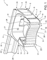
- Fig. 1 shows a holder 1 according to the invention.
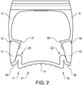
- Fig. 2 shows a top view of the holder
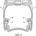
- Fig. 3 shows a cut top view of a first example of the holder
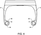
- Fig. 4 shows a cut view of a second example of the holder.
- the holder comprises a bracket 2 and a holder element 3 supported by the bracket.
- the bracket comprises a base part 4 having a first arm 5 and a second arm 6.
- the base part is preferably injection moulded in one piece from e.g. a suitable plastic material, and may be reinforced with additional fibers.
- the first arm and the second arm are preferably designed such that they are somewhat flexible. In this way, the arms can bend outwards which allows for a larger gripping range of the holder.
- the bracket is provided with a suitable height, which is adapted to the object to be held. A suitable height for normal household tools, such as rakes or brooms, etc, is in the range of 1-3 cm.
- each bracket arm 5, 6 is provided with a longitudinal semi-circular groove 35, 36 adapted to cooperate with a longitudinal circular hinge pin 37, 38 of the holder element 3.
- a semi-circular groove is provided with a jaw opening that is narrower than the diameter of the corresponding hinge pin. In this way, a snap connection is created, which forms a hinge joint.
- the jaw is preferably designed such that the holder element can easily be inserted and removed without damaging the holder element, and such that the holder element provides a secure grip of an object.
- the bracket is further provided with an attachment means adapted to allow the holder to be mounted to a mounting rail.
- the holder can be mounted to a mounting rail in different ways.
- the bracket is provided with an upper attachment groove 24 and a lower attachment groove 25 that are adapted to grip an upper mounting edge 33 and a lower mounting edge 34 of a mounting rail 32.
- the upper attachment groove is preferably designed such that the holder can only be attached to and removed from the mounting rail in a specific angled position, e.g. when the angle between the holder and the mounting rail is in a range between 30 to 45 degrees.
- the advantage of this is that the holder will not disengage easily from the mounting rail, even if the locking device breaks or comes loose and the holder is pushed upwards.
- the bracket further comprises a locking device 26 which is adapted to secure the holder in a chosen position on the mounting rail.
- the locking device can be designed in different ways.
- the locking device comprises a flap that can be operated by hand when the holder is to be adjusted on the mounting rail or when the holder is to be removed.
- the locking device is provided with a snap action function that will interact with the lower mounting edge of the mounting rail such that the flap does not have to be operated when the holder is mounted on the mounting rail.
- the bracket may also be provided with mounting holes 31, which can be used when the holder is to be mounted to a structure with screws.
- the holder element 3 comprises a flexible gripping section 9, a first pivoting arm 10 and a second pivoting arm 11.
- the pivoting arms are stiff and are not adapted to flex.
- the pivoting arms are fixedly attached to the gripping section and may be attached by permanent glue or the like. More preferably, the holder element is produced in a two component procedure, where the gripping section and the pivoting arms are injection moulded to each other in the same production step. In this way, a reliable attachment of the gripping section and the pivoting arms is obtained.
- a further advantage is that such a production process prevents hidden spaces to form, which is of advantage when the holder is used in clean environments, where the holder must be cleaned.
- the pivoting arms are preferably made from a plastic material, such as a polyamide, and may be reinforced with additional fibers.
- the gripping section is made from an elastic material, such as rubber, plastic or silicone.
- each pivoting arm 10, 11 is pivotably suspended to the bracket arms 5, 6 at the hinge joints 7, 8.
- the hinge joints allow the pivoting arms to rotate around the outer ends of the bracket arms, such that the pivoting arms can pivot inwards, towards the rear side of the bracket.
- the outer end 14, 15 of each pivoting arm is fixedly attached to the outer ends 16, 17 of the gripping section.
- the surface of the center part of the gripping section is further provided with protruding ribs 30 which will help to hold an object in place, especially objects that are not circular.
- the hinge joints 7, 8 consists of the longitudinal grooves 35, 36 of the bracket arms and the hinge pins 37, 38 of the pivoting arms 10, 11. This creates a hinge joint that allows the pivoting arms to rotate between an outer position, in which the holder element is in a receiving position 27, to an inner position, in which the holder element is in a holding position 28.
- the rotation of the pivoting arms is preferably restricted by outer and inner stops.
- the gripping section is further provided with expansion sections 22, 23.
- a first expansion section 22 is provided between the first end 16 of the gripping section 9 and the outer end 14 of the first pivoting arm 10.
- a second expansion section 23 is provided between the second end 17 of the gripping section 9 and the outer end 15 of the second pivoting arm 11.
- the expansion sections will help to hold larger objects. When a smaller object is held, the expansion section will stay in its preformed shape, since the object will be held by the centre part of the gripping section. When an object having a larger diameter is to be held, the expansion sections will expand such that the length of the gripping section increases, and the object can be held in a secure way.
- the holder is also provided with stop members that restrict the angular movement of the pivoting arms and helps to define the receiving position and the holding position.
- the stop members can either be arranged on the bracket arms 5, 6 or on the pivoting arms 10, 11.
- the bracket arms are provided with inner stop members 20, 21 that restrict the inward movement of the pivoting arms. In this way, there is no risk that one pivoting arm will stick inside the bracket due to incorrect handling.
- the bracket arms are in the shown example further provided with outer stop members 18, 19 which restrict the outward rotation of the pivoting arms. In this way, the holder element will be held in a well-defined receiving position.
- Fig. 4 another example of a hinge joint is shown.
- the hinge joints 7, 8 consist of short hinge pins extending inwards from the upper and lower part of the pivoting arm.
- Each hinge pin is provided with a bevel in order to facilitate the mounting of the pivoting arms on the bracket arms.
- Each bracket arm is provided with an upper and a lower hole that corresponds to the hinge pins. The hole may also run through the complete outer end of the bracket arms.
- through holes 41, 42 are shown.
- the first hole 41 is also provided with an inner stop member 43 and an outer stop member 44 that will correspond to a matching lip of the first hinge pin.
- the second hole 42 is provided with an inner stop member 45 and an outer stop member 46 that will correspond to a matching lip of the second hinge pin. The stop members and the lip will restrict the inward and outward rotation of the pivoting arm in the same way as described above.
- the inner end of the upper and lower part of the pivoting arm is preferably somewhat flexible, such that the upper and lower part of the pivoting arm can move somewhat outwards.
- the hinge pins can move somewhat outwards, away from each other, which will simplify the mounting of the pivoting arm to the bracket arm.
- This will also allow the holder element to be removed from the bracket. It is of advantage to be able to remove the holder element. This simplifies the replacement of a damage holder element and allows the holder to be thoroughly cleaned, which is important e.g. in the food industry and in hospitals.
- each hinge joint will comprise a separate mounting pin that attaches the pivoting arm to the bracket arm.
- the mounting pin is preferably locked to the bracket arm in a suitable manner, e.g. by friction or resilient hooks. In this way, it is possible to remove the mounting pins if a holder element is to be removed e.g. for cleaning purposes or is to be replaced. It is also possible to fasten the mounting pin in a permanent way, e.g. by using glue or heat melting, such that the holder element cannot be removed.
- the holder When the holder is empty, the holder will be in a receiving position 27, as is shown in Fig. 2 .
- the pivoting arms extend forwards and the holder element is substantially flat.
- the pivoting arms abut on the outer stop members, which prevent the pivoting arms to rotate too far in an outward direction.
- the holder element is provided with a slight radius, in order to visualize the insertion position clearer.
- the holder is adapted to hold objects of varying sizes. In one example, the holder is adapted to hold objects with a diameter from 15 mm up to 40 mm. Other ranges are of course possible, but the purpose of the holder is to provide a wide holding range such that different sized holders are not necessary. It is also possible to adapt a holder for other sizes.
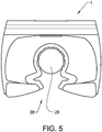
- Fig. 5 shows the holder holding a relatively small object in a holding position 28.
- an object 29 is held by the center part of the gripping section 9.
- the object is held within the bracket arms.
- the gripping section is enough for holding the object, and the expansion sections have not expanded.
- the pivoting arms have rotated inwards by more than 90 degrees such that the pivoting arms points inwards and abut the inner stop members 20, 21.
- Fig. 6 shows the holder holding a relatively large object in a holding position 28.
- an object 29 is held by the center part of the gripping section 9 and the bearing surfaces 39, 40. Since the object is larger, the expansion sections have expanded in order to allow the larger diameter to be held by the gripping section.
- the object is also supported by the bearing surfaces at the outer ends of the gripping device.
- the pivoting arms have rotated inwards by more than 90 degrees such that the pivoting arms points inwards and abut the inner stop members 20, 21.
Landscapes
- Engineering & Computer Science (AREA)
- Mechanical Engineering (AREA)
- General Engineering & Computer Science (AREA)
- Clamps And Clips (AREA)
- Supports Or Holders For Household Use (AREA)
- Supports For Pipes And Cables (AREA)
- Hooks, Suction Cups, And Attachment By Adhesive Means (AREA)
- Cleaning Implements For Floors, Carpets, Furniture, Walls, And The Like (AREA)
- Gripping Jigs, Holding Jigs, And Positioning Jigs (AREA)
Priority Applications (1)
| Application Number | Priority Date | Filing Date | Title |
|---|---|---|---|
| PL15849926T PL3206840T3 (pl) | 2014-10-17 | 2015-10-13 | Uchwyt na przedmioty |
Applications Claiming Priority (2)
| Application Number | Priority Date | Filing Date | Title |
|---|---|---|---|
| SE1451245A SE538395C2 (en) | 2014-10-17 | 2014-10-17 | Holder for objects |
| PCT/SE2015/051084 WO2016060606A1 (en) | 2014-10-17 | 2015-10-13 | Holder for objects |
Publications (3)
| Publication Number | Publication Date |
|---|---|
| EP3206840A1 EP3206840A1 (en) | 2017-08-23 |
| EP3206840A4 EP3206840A4 (en) | 2018-12-26 |
| EP3206840B1 true EP3206840B1 (en) | 2020-03-18 |
Family
ID=55747018
Family Applications (1)
| Application Number | Title | Priority Date | Filing Date |
|---|---|---|---|
| EP15849926.9A Active EP3206840B1 (en) | 2014-10-17 | 2015-10-13 | Holder for objects |
Country Status (15)
| Country | Link |
|---|---|
| US (1) | US10125919B2 (ru) |
| EP (1) | EP3206840B1 (ru) |
| JP (1) | JP6595607B2 (ru) |
| KR (1) | KR102097195B1 (ru) |
| CN (1) | CN107073701B (ru) |
| AU (1) | AU2015330999B2 (ru) |
| CA (1) | CA2964194C (ru) |
| DK (1) | DK3206840T3 (ru) |
| ES (1) | ES2796103T3 (ru) |
| MX (1) | MX2017004697A (ru) |
| PL (1) | PL3206840T3 (ru) |
| RU (1) | RU2701803C2 (ru) |
| SE (1) | SE538395C2 (ru) |
| SG (1) | SG11201702568QA (ru) |
| WO (1) | WO2016060606A1 (ru) |
Families Citing this family (14)
| Publication number | Priority date | Publication date | Assignee | Title |
|---|---|---|---|---|
| BR112017001632B1 (pt) | 2014-09-01 | 2022-08-09 | Electrolux Appliances Aktiebolag | Conjunto de retenção, prateleira e máquina de lavar louça |
| US10165927B2 (en) * | 2014-09-01 | 2019-01-01 | Electrolux Appliances Aktiebolag | Holding assembly |
| US10337542B2 (en) * | 2017-02-28 | 2019-07-02 | The Boeing Company | Curtain retention bracket |
| US20180256766A1 (en) * | 2017-03-13 | 2018-09-13 | Avalign Technologies, Inc. | Bracket assembly |
| CN208085652U (zh) * | 2018-04-23 | 2018-11-13 | 延锋彼欧汽车外饰系统有限公司 | 一种支撑杆的自锁结构和包括该自锁结构的格栅总成 |
| CN108738440A (zh) * | 2018-06-15 | 2018-11-06 | 解晓莉 | 一种农业机械连接装置 |
| DE102019113620A1 (de) * | 2019-05-22 | 2020-11-26 | Elkamet Kunststofftechnik Gmbh | Befestigungsanordnung |
| US11092401B2 (en) * | 2019-05-30 | 2021-08-17 | Thomas Kubiniec | Upper saddle to secure the barrel of a weapon for weapon storage |
| US11266275B1 (en) | 2019-08-09 | 2022-03-08 | Interdesign, Inc. | Shower caddy grip hook and accessory grip lock |
| RU202402U1 (ru) * | 2020-03-16 | 2021-02-16 | Евгений Тимофеевич Шумал | Резиновый стяжной хомут для закрепления тела |
| US20210315769A1 (en) * | 2020-04-08 | 2021-10-14 | Bardia Shemiranipour | Universal Ischemic Compression Device |
| US11006814B1 (en) * | 2020-06-04 | 2021-05-18 | Bsh Home Appliances Corporation | Stemware support/cup shelf for dishwasher |
| US11326851B1 (en) * | 2021-02-24 | 2022-05-10 | James Oldham | Automatic rifle storage assembly |
| KR102596860B1 (ko) * | 2021-05-10 | 2023-10-31 | (주)엘엑스하우시스 | 차량용 충전 도어 조립체 |
Family Cites Families (17)
| Publication number | Priority date | Publication date | Assignee | Title |
|---|---|---|---|---|
| US2379060A (en) | 1944-04-26 | 1945-06-26 | Newell G Bacheldor | Article holder |
| SE8303608D0 (sv) * | 1983-06-23 | 1983-06-23 | Bengt Forsberg | Hallaranordning |
| SU1559225A1 (ru) * | 1987-12-30 | 1990-04-23 | Центральный научно-исследовательский автомобильный и автомоторный институт "НАМИ" | Способ получени соединени |
| ES1017497Y (es) * | 1991-04-04 | 1992-11-16 | Saint Genis, S.A. | Abrazadera flexible para soporte de mangos y similares en vertical. |
| RU2140586C1 (ru) * | 1997-04-02 | 1999-10-27 | Акционерное общество "АвтоВАЗ" | Двухэлементный зажим |
| CN2496800Y (zh) | 2001-09-22 | 2002-06-26 | 谢云龙 | 工具夹 |
| US7185796B2 (en) * | 2003-10-08 | 2007-03-06 | Armament Systems & Procedures, Inc. | Baton scabbard with roller clamp retention |
| SE525905C2 (sv) * | 2003-10-30 | 2005-05-24 | Bengt Forsberg | Hållare för föremål |
| US6932312B1 (en) | 2004-02-18 | 2005-08-23 | Wen-Chun Chen | Suspension device for a tool handle |
| US7861871B2 (en) * | 2006-07-31 | 2011-01-04 | Jui-Chien Kao | Hand tool rack |
| US7669723B2 (en) * | 2007-10-03 | 2010-03-02 | Jui-Chien Kao | Tool suspension device |
| CN101407057B (zh) * | 2007-10-11 | 2011-07-13 | 高瑞乾 | 双轨式手工具吊架 |
| JP5075794B2 (ja) * | 2008-11-10 | 2012-11-21 | 山崎産業株式会社 | 棒状部保持器 |
| US20110174752A1 (en) * | 2010-01-19 | 2011-07-21 | Wan-Yi Liao | Structure of tool hanging rack having direction-changeable diagonally-arranged dual-layered retention receptacle slot |
| CN202161280U (zh) * | 2011-07-06 | 2012-03-14 | 吕恒锴 | 拖把悬挂架 |
| JP5912470B2 (ja) | 2011-12-08 | 2016-04-27 | 株式会社テラモト | 棒状部材用ホルダ |
| US9597792B1 (en) * | 2015-11-12 | 2017-03-21 | Jui-Chien Kao | Hand tool hanger |
-
2014
- 2014-10-17 SE SE1451245A patent/SE538395C2/en unknown
-
2015
- 2015-10-13 SG SG11201702568QA patent/SG11201702568QA/en unknown
- 2015-10-13 WO PCT/SE2015/051084 patent/WO2016060606A1/en active Application Filing
- 2015-10-13 JP JP2017540537A patent/JP6595607B2/ja active Active
- 2015-10-13 EP EP15849926.9A patent/EP3206840B1/en active Active
- 2015-10-13 CA CA2964194A patent/CA2964194C/en active Active
- 2015-10-13 PL PL15849926T patent/PL3206840T3/pl unknown
- 2015-10-13 RU RU2017116977A patent/RU2701803C2/ru active
- 2015-10-13 KR KR1020177013285A patent/KR102097195B1/ko active IP Right Grant
- 2015-10-13 AU AU2015330999A patent/AU2015330999B2/en active Active
- 2015-10-13 MX MX2017004697A patent/MX2017004697A/es active IP Right Grant
- 2015-10-13 US US15/519,796 patent/US10125919B2/en active Active
- 2015-10-13 CN CN201580055650.9A patent/CN107073701B/zh active Active
- 2015-10-13 DK DK15849926.9T patent/DK3206840T3/da active
- 2015-10-13 ES ES15849926T patent/ES2796103T3/es active Active
Non-Patent Citations (1)
| Title |
|---|
| None * |
Also Published As
| Publication number | Publication date |
|---|---|
| RU2701803C2 (ru) | 2019-10-01 |
| CN107073701A (zh) | 2017-08-18 |
| JP2017532515A (ja) | 2017-11-02 |
| DK3206840T3 (da) | 2020-06-08 |
| RU2017116977A (ru) | 2018-11-19 |
| KR20170071555A (ko) | 2017-06-23 |
| SE538395C2 (en) | 2016-06-14 |
| CA2964194A1 (en) | 2016-04-21 |
| KR102097195B1 (ko) | 2020-04-03 |
| AU2015330999A1 (en) | 2017-04-27 |
| SG11201702568QA (en) | 2017-04-27 |
| US10125919B2 (en) | 2018-11-13 |
| EP3206840A4 (en) | 2018-12-26 |
| US20170254472A1 (en) | 2017-09-07 |
| AU2015330999B2 (en) | 2020-08-06 |
| WO2016060606A1 (en) | 2016-04-21 |
| EP3206840A1 (en) | 2017-08-23 |
| RU2017116977A3 (ru) | 2019-04-30 |
| SE1451245A1 (en) | 2016-04-18 |
| ES2796103T3 (es) | 2020-11-25 |
| PL3206840T3 (pl) | 2020-09-07 |
| MX2017004697A (es) | 2017-10-02 |
| CA2964194C (en) | 2022-11-22 |
| CN107073701B (zh) | 2020-11-20 |
| JP6595607B2 (ja) | 2019-10-23 |
Similar Documents
| Publication | Publication Date | Title |
|---|---|---|
| EP3206840B1 (en) | Holder for objects | |
| CN102422337B (zh) | 悬吊装置 | |
| JP4505815B2 (ja) | 歯列矯正装置 | |
| EP1360925A2 (en) | Cleaning tool holder | |
| BR112017001632B1 (pt) | Conjunto de retenção, prateleira e máquina de lavar louça | |
| US20150122961A1 (en) | Suspended Tool Holder and Modified Tool | |
| JP2016137562A (ja) | 汎用プライヤ | |
| CA2470962A1 (en) | Bird feeding apparatus | |
| JP6324268B2 (ja) | チューブ保持具 | |
| US8317147B1 (en) | Solar light stick holder device | |
| WO2007105787A1 (ja) | 洗浄装置及びその取付具 | |
| KR101675937B1 (ko) | 용기의 손잡이 결합구조 | |
| US11081309B2 (en) | Light bulb removing and installing assemblies | |
| US20090211935A1 (en) | Display apparatus for implements with handles and working ends | |
| JP2020065615A (ja) | 処理器 | |
| KR101391721B1 (ko) | 옷걸이 행거 | |
| US11287084B1 (en) | Holder for scanner guns and other devices and methods of making and using | |
| KR20180001792U (ko) | S-자형 집게 | |
| GB2368780A (en) | Mop head strand bundle clamp with two mutually, and base, engaging clamping portions | |
| KR101744862B1 (ko) | 카울탑의 호스 조립구조 | |
| KR20140003704U (ko) | 낚싯대 거치대 | |
| JP2011098184A (ja) | 柄付ブラシ | |
| TWM530096U (zh) | 可適用於各種湯匙的輔助器 | |
| JP2006297031A (ja) | ハンガー保持器 |
Legal Events
| Date | Code | Title | Description |
|---|---|---|---|
| STAA | Information on the status of an ep patent application or granted ep patent |
Free format text: STATUS: THE INTERNATIONAL PUBLICATION HAS BEEN MADE |
|
| PUAI | Public reference made under article 153(3) epc to a published international application that has entered the european phase |
Free format text: ORIGINAL CODE: 0009012 |
|
| STAA | Information on the status of an ep patent application or granted ep patent |
Free format text: STATUS: REQUEST FOR EXAMINATION WAS MADE |
|
| 17P | Request for examination filed |
Effective date: 20170412 |
|
| AK | Designated contracting states |
Kind code of ref document: A1 Designated state(s): AL AT BE BG CH CY CZ DE DK EE ES FI FR GB GR HR HU IE IS IT LI LT LU LV MC MK MT NL NO PL PT RO RS SE SI SK SM TR |
|
| AX | Request for extension of the european patent |
Extension state: BA ME |
|
| DAV | Request for validation of the european patent (deleted) | ||
| DAX | Request for extension of the european patent (deleted) | ||
| A4 | Supplementary search report drawn up and despatched |
Effective date: 20181128 |
|
| RIC1 | Information provided on ipc code assigned before grant |
Ipc: B25H 3/00 20060101AFI20181123BHEP Ipc: F16B 2/20 20060101ALI20181123BHEP Ipc: B25H 3/04 20060101ALI20181123BHEP |
|
| GRAP | Despatch of communication of intention to grant a patent |
Free format text: ORIGINAL CODE: EPIDOSNIGR1 |
|
| STAA | Information on the status of an ep patent application or granted ep patent |
Free format text: STATUS: GRANT OF PATENT IS INTENDED |
|
| INTG | Intention to grant announced |
Effective date: 20191023 |
|
| GRAS | Grant fee paid |
Free format text: ORIGINAL CODE: EPIDOSNIGR3 |
|
| GRAA | (expected) grant |
Free format text: ORIGINAL CODE: 0009210 |
|
| STAA | Information on the status of an ep patent application or granted ep patent |
Free format text: STATUS: THE PATENT HAS BEEN GRANTED |
|
| AK | Designated contracting states |
Kind code of ref document: B1 Designated state(s): AL AT BE BG CH CY CZ DE DK EE ES FI FR GB GR HR HU IE IS IT LI LT LU LV MC MK MT NL NO PL PT RO RS SE SI SK SM TR |
|
| REG | Reference to a national code |
Ref country code: GB Ref legal event code: FG4D |
|
| REG | Reference to a national code |
Ref country code: DE Ref legal event code: R096 Ref document number: 602015049150 Country of ref document: DE |
|
| REG | Reference to a national code |
Ref country code: AT Ref legal event code: REF Ref document number: 1245372 Country of ref document: AT Kind code of ref document: T Effective date: 20200415 Ref country code: IE Ref legal event code: FG4D |
|
| REG | Reference to a national code |
Ref country code: DK Ref legal event code: T3 Effective date: 20200603 |
|
| REG | Reference to a national code |
Ref country code: CH Ref legal event code: NV Representative=s name: HEPP WENGER RYFFEL AG, CH |
|
| REG | Reference to a national code |
Ref country code: NL Ref legal event code: FP |
|
| REG | Reference to a national code |
Ref country code: SE Ref legal event code: TRGR |
|
| PG25 | Lapsed in a contracting state [announced via postgrant information from national office to epo] |
Ref country code: RS Free format text: LAPSE BECAUSE OF FAILURE TO SUBMIT A TRANSLATION OF THE DESCRIPTION OR TO PAY THE FEE WITHIN THE PRESCRIBED TIME-LIMIT Effective date: 20200318 Ref country code: NO Free format text: LAPSE BECAUSE OF FAILURE TO SUBMIT A TRANSLATION OF THE DESCRIPTION OR TO PAY THE FEE WITHIN THE PRESCRIBED TIME-LIMIT Effective date: 20200618 Ref country code: FI Free format text: LAPSE BECAUSE OF FAILURE TO SUBMIT A TRANSLATION OF THE DESCRIPTION OR TO PAY THE FEE WITHIN THE PRESCRIBED TIME-LIMIT Effective date: 20200318 |
|
| PG25 | Lapsed in a contracting state [announced via postgrant information from national office to epo] |
Ref country code: LV Free format text: LAPSE BECAUSE OF FAILURE TO SUBMIT A TRANSLATION OF THE DESCRIPTION OR TO PAY THE FEE WITHIN THE PRESCRIBED TIME-LIMIT Effective date: 20200318 Ref country code: GR Free format text: LAPSE BECAUSE OF FAILURE TO SUBMIT A TRANSLATION OF THE DESCRIPTION OR TO PAY THE FEE WITHIN THE PRESCRIBED TIME-LIMIT Effective date: 20200619 Ref country code: HR Free format text: LAPSE BECAUSE OF FAILURE TO SUBMIT A TRANSLATION OF THE DESCRIPTION OR TO PAY THE FEE WITHIN THE PRESCRIBED TIME-LIMIT Effective date: 20200318 Ref country code: BG Free format text: LAPSE BECAUSE OF FAILURE TO SUBMIT A TRANSLATION OF THE DESCRIPTION OR TO PAY THE FEE WITHIN THE PRESCRIBED TIME-LIMIT Effective date: 20200618 |
|
| REG | Reference to a national code |
Ref country code: LT Ref legal event code: MG4D |
|
| PG25 | Lapsed in a contracting state [announced via postgrant information from national office to epo] |
Ref country code: SM Free format text: LAPSE BECAUSE OF FAILURE TO SUBMIT A TRANSLATION OF THE DESCRIPTION OR TO PAY THE FEE WITHIN THE PRESCRIBED TIME-LIMIT Effective date: 20200318 Ref country code: EE Free format text: LAPSE BECAUSE OF FAILURE TO SUBMIT A TRANSLATION OF THE DESCRIPTION OR TO PAY THE FEE WITHIN THE PRESCRIBED TIME-LIMIT Effective date: 20200318 Ref country code: SK Free format text: LAPSE BECAUSE OF FAILURE TO SUBMIT A TRANSLATION OF THE DESCRIPTION OR TO PAY THE FEE WITHIN THE PRESCRIBED TIME-LIMIT Effective date: 20200318 Ref country code: CZ Free format text: LAPSE BECAUSE OF FAILURE TO SUBMIT A TRANSLATION OF THE DESCRIPTION OR TO PAY THE FEE WITHIN THE PRESCRIBED TIME-LIMIT Effective date: 20200318 Ref country code: RO Free format text: LAPSE BECAUSE OF FAILURE TO SUBMIT A TRANSLATION OF THE DESCRIPTION OR TO PAY THE FEE WITHIN THE PRESCRIBED TIME-LIMIT Effective date: 20200318 Ref country code: LT Free format text: LAPSE BECAUSE OF FAILURE TO SUBMIT A TRANSLATION OF THE DESCRIPTION OR TO PAY THE FEE WITHIN THE PRESCRIBED TIME-LIMIT Effective date: 20200318 Ref country code: PT Free format text: LAPSE BECAUSE OF FAILURE TO SUBMIT A TRANSLATION OF THE DESCRIPTION OR TO PAY THE FEE WITHIN THE PRESCRIBED TIME-LIMIT Effective date: 20200812 Ref country code: IS Free format text: LAPSE BECAUSE OF FAILURE TO SUBMIT A TRANSLATION OF THE DESCRIPTION OR TO PAY THE FEE WITHIN THE PRESCRIBED TIME-LIMIT Effective date: 20200718 |
|
| REG | Reference to a national code |
Ref country code: AT Ref legal event code: MK05 Ref document number: 1245372 Country of ref document: AT Kind code of ref document: T Effective date: 20200318 |
|
| REG | Reference to a national code |
Ref country code: ES Ref legal event code: FG2A Ref document number: 2796103 Country of ref document: ES Kind code of ref document: T3 Effective date: 20201125 |
|
| REG | Reference to a national code |
Ref country code: DE Ref legal event code: R097 Ref document number: 602015049150 Country of ref document: DE |
|
| PLBE | No opposition filed within time limit |
Free format text: ORIGINAL CODE: 0009261 |
|
| STAA | Information on the status of an ep patent application or granted ep patent |
Free format text: STATUS: NO OPPOSITION FILED WITHIN TIME LIMIT |
|
| PG25 | Lapsed in a contracting state [announced via postgrant information from national office to epo] |
Ref country code: AT Free format text: LAPSE BECAUSE OF FAILURE TO SUBMIT A TRANSLATION OF THE DESCRIPTION OR TO PAY THE FEE WITHIN THE PRESCRIBED TIME-LIMIT Effective date: 20200318 |
|
| 26N | No opposition filed |
Effective date: 20201221 |
|
| PG25 | Lapsed in a contracting state [announced via postgrant information from national office to epo] |
Ref country code: SI Free format text: LAPSE BECAUSE OF FAILURE TO SUBMIT A TRANSLATION OF THE DESCRIPTION OR TO PAY THE FEE WITHIN THE PRESCRIBED TIME-LIMIT Effective date: 20200318 |
|
| PG25 | Lapsed in a contracting state [announced via postgrant information from national office to epo] |
Ref country code: MC Free format text: LAPSE BECAUSE OF FAILURE TO SUBMIT A TRANSLATION OF THE DESCRIPTION OR TO PAY THE FEE WITHIN THE PRESCRIBED TIME-LIMIT Effective date: 20200318 Ref country code: LU Free format text: LAPSE BECAUSE OF NON-PAYMENT OF DUE FEES Effective date: 20201013 |
|
| PG25 | Lapsed in a contracting state [announced via postgrant information from national office to epo] |
Ref country code: IE Free format text: LAPSE BECAUSE OF NON-PAYMENT OF DUE FEES Effective date: 20201013 |
|
| PG25 | Lapsed in a contracting state [announced via postgrant information from national office to epo] |
Ref country code: MT Free format text: LAPSE BECAUSE OF FAILURE TO SUBMIT A TRANSLATION OF THE DESCRIPTION OR TO PAY THE FEE WITHIN THE PRESCRIBED TIME-LIMIT Effective date: 20200318 Ref country code: CY Free format text: LAPSE BECAUSE OF FAILURE TO SUBMIT A TRANSLATION OF THE DESCRIPTION OR TO PAY THE FEE WITHIN THE PRESCRIBED TIME-LIMIT Effective date: 20200318 |
|
| PG25 | Lapsed in a contracting state [announced via postgrant information from national office to epo] |
Ref country code: MK Free format text: LAPSE BECAUSE OF FAILURE TO SUBMIT A TRANSLATION OF THE DESCRIPTION OR TO PAY THE FEE WITHIN THE PRESCRIBED TIME-LIMIT Effective date: 20200318 Ref country code: AL Free format text: LAPSE BECAUSE OF FAILURE TO SUBMIT A TRANSLATION OF THE DESCRIPTION OR TO PAY THE FEE WITHIN THE PRESCRIBED TIME-LIMIT Effective date: 20200318 |
|
| P01 | Opt-out of the competence of the unified patent court (upc) registered |
Effective date: 20230524 |
|
| PGFP | Annual fee paid to national office [announced via postgrant information from national office to epo] |
Ref country code: NL Payment date: 20230919 Year of fee payment: 9 Ref country code: IT Payment date: 20230920 Year of fee payment: 9 Ref country code: GB Payment date: 20230920 Year of fee payment: 9 |
|
| PGFP | Annual fee paid to national office [announced via postgrant information from national office to epo] |
Ref country code: SE Payment date: 20230920 Year of fee payment: 9 Ref country code: PL Payment date: 20230914 Year of fee payment: 9 Ref country code: FR Payment date: 20230921 Year of fee payment: 9 Ref country code: DK Payment date: 20230828 Year of fee payment: 9 Ref country code: BE Payment date: 20230920 Year of fee payment: 9 |
|
| PGFP | Annual fee paid to national office [announced via postgrant information from national office to epo] |
Ref country code: TR Payment date: 20231013 Year of fee payment: 9 Ref country code: DE Payment date: 20230919 Year of fee payment: 9 Ref country code: CH Payment date: 20231102 Year of fee payment: 9 |
|
| PGFP | Annual fee paid to national office [announced via postgrant information from national office to epo] |
Ref country code: ES Payment date: 20240124 Year of fee payment: 9 |