EP3206597B1 - Sonden, systeme für breit gebündelten ultraschallantrieb - Google Patents
Sonden, systeme für breit gebündelten ultraschallantrieb Download PDFInfo
- Publication number
- EP3206597B1 EP3206597B1 EP15851498.4A EP15851498A EP3206597B1 EP 3206597 B1 EP3206597 B1 EP 3206597B1 EP 15851498 A EP15851498 A EP 15851498A EP 3206597 B1 EP3206597 B1 EP 3206597B1
- Authority
- EP
- European Patent Office
- Prior art keywords
- therapy
- probe
- ultrasonic
- region
- imaging
- Prior art date
- Legal status (The legal status is an assumption and is not a legal conclusion. Google has not performed a legal analysis and makes no representation as to the accuracy of the status listed.)
- Active
Links
- 239000000523 sample Substances 0.000 title claims description 236
- 238000002560 therapeutic procedure Methods 0.000 claims description 283
- 238000003384 imaging method Methods 0.000 claims description 79
- 208000000913 Kidney Calculi Diseases 0.000 claims description 43
- 206010029148 Nephrolithiasis Diseases 0.000 claims description 43
- 238000001816 cooling Methods 0.000 claims description 31
- 239000012634 fragment Substances 0.000 claims description 26
- 230000005855 radiation Effects 0.000 claims description 23
- 238000002604 ultrasonography Methods 0.000 claims description 15
- 230000007246 mechanism Effects 0.000 claims description 9
- 230000001360 synchronised effect Effects 0.000 claims description 8
- 230000004044 response Effects 0.000 claims description 4
- 230000007704 transition Effects 0.000 claims description 4
- 230000008859 change Effects 0.000 claims description 3
- 238000012545 processing Methods 0.000 claims description 3
- 239000004575 stone Substances 0.000 description 42
- 238000000034 method Methods 0.000 description 31
- 230000008901 benefit Effects 0.000 description 7
- XLYOFNOQVPJJNP-UHFFFAOYSA-N water Substances O XLYOFNOQVPJJNP-UHFFFAOYSA-N 0.000 description 7
- 239000000463 material Substances 0.000 description 5
- 238000011282 treatment Methods 0.000 description 5
- 210000003734 kidney Anatomy 0.000 description 4
- 239000007788 liquid Substances 0.000 description 4
- 238000012285 ultrasound imaging Methods 0.000 description 4
- OKTJSMMVPCPJKN-UHFFFAOYSA-N Carbon Chemical compound [C] OKTJSMMVPCPJKN-UHFFFAOYSA-N 0.000 description 3
- 229910052782 aluminium Inorganic materials 0.000 description 3
- XAGFODPZIPBFFR-UHFFFAOYSA-N aluminium Chemical compound [Al] XAGFODPZIPBFFR-UHFFFAOYSA-N 0.000 description 3
- 230000008878 coupling Effects 0.000 description 3
- 238000010168 coupling process Methods 0.000 description 3
- 238000005859 coupling reaction Methods 0.000 description 3
- 238000013461 design Methods 0.000 description 3
- 239000012530 fluid Substances 0.000 description 3
- 229910002804 graphite Inorganic materials 0.000 description 3
- 239000010439 graphite Substances 0.000 description 3
- 238000010438 heat treatment Methods 0.000 description 3
- 229910052451 lead zirconate titanate Inorganic materials 0.000 description 3
- 229910052751 metal Inorganic materials 0.000 description 3
- 239000002184 metal Substances 0.000 description 3
- 239000004033 plastic Substances 0.000 description 3
- 229920003023 plastic Polymers 0.000 description 3
- 238000004088 simulation Methods 0.000 description 3
- 230000008685 targeting Effects 0.000 description 3
- 238000012360 testing method Methods 0.000 description 3
- 241000581613 Alchemilla arvensis Species 0.000 description 2
- 206010050337 Cerumen impaction Diseases 0.000 description 2
- 208000009911 Urinary Calculi Diseases 0.000 description 2
- 238000009246 art therapy Methods 0.000 description 2
- 239000000919 ceramic Substances 0.000 description 2
- 239000002131 composite material Substances 0.000 description 2
- 208000037265 diseases, disorders, signs and symptoms Diseases 0.000 description 2
- 230000000694 effects Effects 0.000 description 2
- 238000011065 in-situ storage Methods 0.000 description 2
- 239000003921 oil Substances 0.000 description 2
- 238000011160 research Methods 0.000 description 2
- 238000011125 single therapy Methods 0.000 description 2
- 210000000626 ureter Anatomy 0.000 description 2
- 230000000007 visual effect Effects 0.000 description 2
- 238000012935 Averaging Methods 0.000 description 1
- 206010010774 Constipation Diseases 0.000 description 1
- 201000003883 Cystic fibrosis Diseases 0.000 description 1
- 239000004593 Epoxy Substances 0.000 description 1
- LFQSCWFLJHTTHZ-UHFFFAOYSA-N Ethanol Chemical compound CCO LFQSCWFLJHTTHZ-UHFFFAOYSA-N 0.000 description 1
- 241000124008 Mammalia Species 0.000 description 1
- 206010028735 Nasal congestion Diseases 0.000 description 1
- 208000007536 Thrombosis Diseases 0.000 description 1
- 208000006568 Urinary Bladder Calculi Diseases 0.000 description 1
- 208000012931 Urologic disease Diseases 0.000 description 1
- 230000003213 activating effect Effects 0.000 description 1
- 230000004913 activation Effects 0.000 description 1
- 230000009286 beneficial effect Effects 0.000 description 1
- 210000003445 biliary tract Anatomy 0.000 description 1
- 230000000903 blocking effect Effects 0.000 description 1
- 239000008280 blood Substances 0.000 description 1
- 210000004369 blood Anatomy 0.000 description 1
- 238000009529 body temperature measurement Methods 0.000 description 1
- 230000000747 cardiac effect Effects 0.000 description 1
- 239000004568 cement Substances 0.000 description 1
- 210000002939 cerumen Anatomy 0.000 description 1
- 238000002648 combination therapy Methods 0.000 description 1
- 230000000052 comparative effect Effects 0.000 description 1
- 230000001186 cumulative effect Effects 0.000 description 1
- 238000002059 diagnostic imaging Methods 0.000 description 1
- 238000010586 diagram Methods 0.000 description 1
- 230000001079 digestive effect Effects 0.000 description 1
- 208000010643 digestive system disease Diseases 0.000 description 1
- 238000006073 displacement reaction Methods 0.000 description 1
- 239000000428 dust Substances 0.000 description 1
- 125000003700 epoxy group Chemical group 0.000 description 1
- 238000013401 experimental design Methods 0.000 description 1
- 238000002474 experimental method Methods 0.000 description 1
- 238000013467 fragmentation Methods 0.000 description 1
- 238000006062 fragmentation reaction Methods 0.000 description 1
- 230000006870 function Effects 0.000 description 1
- 210000000232 gallbladder Anatomy 0.000 description 1
- 239000000499 gel Substances 0.000 description 1
- 230000036541 health Effects 0.000 description 1
- 238000010191 image analysis Methods 0.000 description 1
- 238000000338 in vitro Methods 0.000 description 1
- 238000001727 in vivo Methods 0.000 description 1
- 208000017169 kidney disease Diseases 0.000 description 1
- 239000004816 latex Substances 0.000 description 1
- 229920000126 latex Polymers 0.000 description 1
- HFGPZNIAWCZYJU-UHFFFAOYSA-N lead zirconate titanate Chemical compound [O-2].[O-2].[O-2].[O-2].[O-2].[Ti+4].[Zr+4].[Pb+2] HFGPZNIAWCZYJU-UHFFFAOYSA-N 0.000 description 1
- 238000013160 medical therapy Methods 0.000 description 1
- 238000013021 overheating Methods 0.000 description 1
- 230000035515 penetration Effects 0.000 description 1
- 229920000647 polyepoxide Polymers 0.000 description 1
- 229920000642 polymer Polymers 0.000 description 1
- 230000001376 precipitating effect Effects 0.000 description 1
- 230000008569 process Effects 0.000 description 1
- 230000002035 prolonged effect Effects 0.000 description 1
- 210000001525 retina Anatomy 0.000 description 1
- 229920002631 room-temperature vulcanizate silicone Polymers 0.000 description 1
- 230000035939 shock Effects 0.000 description 1
- -1 siloxanes Chemical class 0.000 description 1
- 238000010408 sweeping Methods 0.000 description 1
- 238000012546 transfer Methods 0.000 description 1
- WFKWXMTUELFFGS-UHFFFAOYSA-N tungsten Chemical compound [W] WFKWXMTUELFFGS-UHFFFAOYSA-N 0.000 description 1
- 229910052721 tungsten Inorganic materials 0.000 description 1
- 239000010937 tungsten Substances 0.000 description 1
- 150000003673 urethanes Chemical class 0.000 description 1
- 208000014001 urinary system disease Diseases 0.000 description 1
- 210000002700 urine Anatomy 0.000 description 1
- 238000004073 vulcanization Methods 0.000 description 1
Images


Classifications
-
- A—HUMAN NECESSITIES
- A61—MEDICAL OR VETERINARY SCIENCE; HYGIENE
- A61B—DIAGNOSIS; SURGERY; IDENTIFICATION
- A61B17/00—Surgical instruments, devices or methods, e.g. tourniquets
- A61B17/22—Implements for squeezing-off ulcers or the like on the inside of inner organs of the body; Implements for scraping-out cavities of body organs, e.g. bones; Calculus removers; Calculus smashing apparatus; Apparatus for removing obstructions in blood vessels, not otherwise provided for
- A61B17/22004—Implements for squeezing-off ulcers or the like on the inside of inner organs of the body; Implements for scraping-out cavities of body organs, e.g. bones; Calculus removers; Calculus smashing apparatus; Apparatus for removing obstructions in blood vessels, not otherwise provided for using mechanical vibrations, e.g. ultrasonic shock waves
-
- A—HUMAN NECESSITIES
- A61—MEDICAL OR VETERINARY SCIENCE; HYGIENE
- A61B—DIAGNOSIS; SURGERY; IDENTIFICATION
- A61B8/00—Diagnosis using ultrasonic, sonic or infrasonic waves
- A61B8/08—Detecting organic movements or changes, e.g. tumours, cysts, swellings
- A61B8/0833—Detecting organic movements or changes, e.g. tumours, cysts, swellings involving detecting or locating foreign bodies or organic structures
- A61B8/085—Detecting organic movements or changes, e.g. tumours, cysts, swellings involving detecting or locating foreign bodies or organic structures for locating body or organic structures, e.g. tumours, calculi, blood vessels, nodules
-
- A—HUMAN NECESSITIES
- A61—MEDICAL OR VETERINARY SCIENCE; HYGIENE
- A61N—ELECTROTHERAPY; MAGNETOTHERAPY; RADIATION THERAPY; ULTRASOUND THERAPY
- A61N7/00—Ultrasound therapy
- A61N7/02—Localised ultrasound hyperthermia
-
- A—HUMAN NECESSITIES
- A61—MEDICAL OR VETERINARY SCIENCE; HYGIENE
- A61B—DIAGNOSIS; SURGERY; IDENTIFICATION
- A61B17/00—Surgical instruments, devices or methods, e.g. tourniquets
- A61B17/22—Implements for squeezing-off ulcers or the like on the inside of inner organs of the body; Implements for scraping-out cavities of body organs, e.g. bones; Calculus removers; Calculus smashing apparatus; Apparatus for removing obstructions in blood vessels, not otherwise provided for
- A61B17/225—Implements for squeezing-off ulcers or the like on the inside of inner organs of the body; Implements for scraping-out cavities of body organs, e.g. bones; Calculus removers; Calculus smashing apparatus; Apparatus for removing obstructions in blood vessels, not otherwise provided for for extracorporeal shock wave lithotripsy [ESWL], e.g. by using ultrasonic waves
- A61B17/2256—Implements for squeezing-off ulcers or the like on the inside of inner organs of the body; Implements for scraping-out cavities of body organs, e.g. bones; Calculus removers; Calculus smashing apparatus; Apparatus for removing obstructions in blood vessels, not otherwise provided for for extracorporeal shock wave lithotripsy [ESWL], e.g. by using ultrasonic waves with means for locating or checking the concrement, e.g. X-ray apparatus, imaging means
- A61B17/2258—Implements for squeezing-off ulcers or the like on the inside of inner organs of the body; Implements for scraping-out cavities of body organs, e.g. bones; Calculus removers; Calculus smashing apparatus; Apparatus for removing obstructions in blood vessels, not otherwise provided for for extracorporeal shock wave lithotripsy [ESWL], e.g. by using ultrasonic waves with means for locating or checking the concrement, e.g. X-ray apparatus, imaging means integrated in a central portion of the shock wave apparatus
-
- A—HUMAN NECESSITIES
- A61—MEDICAL OR VETERINARY SCIENCE; HYGIENE
- A61B—DIAGNOSIS; SURGERY; IDENTIFICATION
- A61B17/00—Surgical instruments, devices or methods, e.g. tourniquets
- A61B17/22—Implements for squeezing-off ulcers or the like on the inside of inner organs of the body; Implements for scraping-out cavities of body organs, e.g. bones; Calculus removers; Calculus smashing apparatus; Apparatus for removing obstructions in blood vessels, not otherwise provided for
- A61B17/22004—Implements for squeezing-off ulcers or the like on the inside of inner organs of the body; Implements for scraping-out cavities of body organs, e.g. bones; Calculus removers; Calculus smashing apparatus; Apparatus for removing obstructions in blood vessels, not otherwise provided for using mechanical vibrations, e.g. ultrasonic shock waves
- A61B2017/22005—Effects, e.g. on tissue
-
- A—HUMAN NECESSITIES
- A61—MEDICAL OR VETERINARY SCIENCE; HYGIENE
- A61B—DIAGNOSIS; SURGERY; IDENTIFICATION
- A61B18/00—Surgical instruments, devices or methods for transferring non-mechanical forms of energy to or from the body
- A61B2018/00005—Cooling or heating of the probe or tissue immediately surrounding the probe
- A61B2018/00011—Cooling or heating of the probe or tissue immediately surrounding the probe with fluids
- A61B2018/00023—Cooling or heating of the probe or tissue immediately surrounding the probe with fluids closed, i.e. without wound contact by the fluid
-
- A—HUMAN NECESSITIES
- A61—MEDICAL OR VETERINARY SCIENCE; HYGIENE
- A61B—DIAGNOSIS; SURGERY; IDENTIFICATION
- A61B18/00—Surgical instruments, devices or methods for transferring non-mechanical forms of energy to or from the body
- A61B2018/00315—Surgical instruments, devices or methods for transferring non-mechanical forms of energy to or from the body for treatment of particular body parts
- A61B2018/00505—Urinary tract
- A61B2018/00511—Kidney
Definitions
- US2011263967 discloses an ultrasonic therapy system configured to apply an acoustic radiation force to move a kidney stone.
- NIDDK National Institute of Diabetes and Digestive and Kidney Diseases
- USDROC Urinary Stone Disease Research Opportunities and Challenges
- the primary viable option is presently the serial use of focused ultrasound to manipulate one stone at a time.
- this serial method is unfeasible. Accordingly, new tools and method for manipulating a plurality of kidney stones within a patient are desirable.
- an ultrasonic therapy system configured to apply a non-lithotriptic acoustic radiation force to a kidney stone.
- An exemplary method of moving one or more target objects using ultrasonic propulsion includes applying a non-lithotriptic acoustic radiation force to a target object using an ultrasonic therapy system as shown and described herein.
- a method of moving one or more kidney stones in a therapy region using ultrasonic propulsion includes using a broadly focused ultrasound therapy probe to apply a force on one or more kidney stones having a diameter of from 0.5 mm to 20 mm disposed within the therapy region, wherein the acoustic radiation force applied to each of the one or more kidney stones is from 50 ⁇ N to 0.5 N, and wherein the acoustic radiation force is not sufficient to fragment the kidney stones.
- the probes are configured to produce an ultrasonic therapy exposure that, when applied to a kidney stone, will exert an acoustic radiation force sufficient to produce ultrasonic propulsion.
- the disclosed probes are engineered to produce a relatively large (both wide and long) therapy region effective to produce ultrasonic propulsion.
- This large therapy region allows the probe to move a plurality of kidney stones (or fragments from lithotripsy) in parallel, thereby providing the user the ability to clear several stones from an area simultaneously.
- This "broadly focused" probe is, in certain embodiments, combined in a single handheld unit with a typical ultrasound imaging probe. By coordinating the ultrasound signals produced by both the therapy probe and the imaging probe a user of the combined probe can image stones in real time as the broadly focused ultrasound moves stones within a patient. Methods of using the probes and systems to move kidney stones are also provided.
- Advantages of the disclosed broadly focused beam include easier alignment.
- the wide beam yields a greater probability of targeting a stone.
- the relatively long therapy region accounts for the difficulty in changing focal depth during use, therefore simplifying targeting.
- the disclosed system allows for simpler cheaper systems, particularly in embodiments that utilize a single therapy transducer ("fixed focus").
- the disclosed embodiments during treatment, yield no "hot spots" of high amplitude (>-6dB compared to focal pressure), making the devices and methods safer and more predictable when applied to patients.
- an ultrasonic therapy system configured to apply a non-lithotriptic acoustic radiation force to a kidney stone.
- an ultrasonic therapy system according to claim 1 is provided.
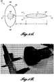
- FIGURE 1A illustrates a combined probe 100 including both a therapy probe 105 and an imaging probe 110. Disposed along axis A of both probes 105 and 110 is the therapy region 115.
- the therapy region 115 is defined herein as the volume of space (e.g., within a patient) subjected to a full-width half-maximum (FWHM) pressure or greater.
- FWHM full-width half-maximum
- the therapy probe 105 will produce a maximum pressure at a certain point in the therapy region 115 and the boundaries of the therapy region 115 are defined by the region wherein the pressure is FWHM in view of the maximum pressure.
- the therapy region 115 has a center point C , a length L, and a width W, and begins a distance D from the therapy probe 105.
- the therapy region "width" is defined as the distance between the locations in the field orthogonal to the acoustic axis A where the pressure reaches -6 dB relative to the peak focal pressure.
- the therapy probe 115 is annular (at least roughly circular) as depicted in FIGURE 1A , having an outside dimension OD.
- the therapy probe 115 is circular in one embodiment.
- the imaging probe 110 is typically rectangular, having a height h and width w.
- the sizes of the combined probe 100 and, relatedly, the therapy probe 105 and imaging probe 110, are of great importance.
- the combined probe 100 must be compact (e.g., OD of 5 cm or less) in order to be easily handheld by an operator and to be maneuverable to position at any point along a patient's skin. These dimensional constraints lead to the coaxial combination of the probes 105 and 110 to form the compact combined probe 100.
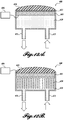
- An exemplary combined probe 100 is pictured in FIGURE 1B .
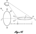
- FIGURE 1C illustrates a system without an integrated imaging probe 110. Instead, a separately disposed imaging probe 110' is utilized. The imaging probe 110' is still coordinated with the therapy probe 105 during use and is still focused on the therapy region 115. However, the imaging probe 110' is not coaxially disposed on axis A. This arrangement does not provide the benefits of ease of use when coaxially focusing on the therapy region 115, although this embodiment may be more easily fabricated from off-the-shelf components because a custom coaxial probe (e.g., combined probe 100) need not be fabricated.
- a custom coaxial probe e.g., combined probe 100
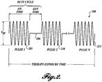
- the therapy probe 105 emits a therapy exposure comprising one or more ultrasonic therapy pules over a therapy exposure time (refer to FIGURE 2 for a visual illustration of the therapy exposure signal).
- a therapy exposure time (refer to FIGURE 2 for a visual illustration of the therapy exposure signal).
- the therapy probe 105 and imaging probe 110 are coordinated such that their signals do not overlap yet images are acquired frequently enough (e.g., at least one frame per second, fps).
- the operator can see the movement of stones in real time and adjust aim and/or focus as needed to accomplish the treatment (e.g., move the stones towards expulsion from the kidney or other region).
- the term "therapy exposure” relates herein to a series of pulses over an exposure time.
- the exposure time is defined in certain embodiments by a user activating the therapy probe by an on switch or other mechanism.
- An exemplary mechanism is on on/off switch, such as a foot-activated switch.
- Several therapy exposures may be utilized by a user during treatment of a patient for a cumulative therapy exposure session. Therapy exposures end when the system is continuously off for a prolonged period (e.g., 1 second or greater). An "off' period between pulses (i.e., when the duty cycle is less than 100%) does not mark the end of a therapy exposure.
- the ultrasonic therapy system is non-lithotriptic and therefore the ultrasound applied by the system is not sufficient to break a kidney stone.
- the purpose of the system is to provide a relatively large therapy region in which the therapy probe produces sufficient acoustic radiation force to move any kidney stones within the therapy region. While the description herein discusses the unusual utility of the systems in moving a plurality of stones or fragments, it will be appreciated that the movement of a single stone, even a single large stone is also contemplated in certain embodiments. As an example, a single large stone may be moved that is blocking the ureter.
- the therapy exposure is an ultrasonic signal as depicted in FIGURE 2 . It can be defined by a number of parameters, including frequency, therapy exposure time, the peak negative pressure in the therapy region, power, intensity, and driving voltage.
- the therapy region is sufficient to exert an acoustic radiation force on a kidney stone having a diameter of from 0.5 mm to 20 mm disposed within the therapy region, wherein the acoustic radiation force applied to the kidney stone is from 50 ⁇ N to 0.5 N, and wherein the acoustic radiation force is not sufficient to fragment the kidney stone.
- This characteristic of the system and therapy region indicates the nature of the force exerted by the therapy probe: non-lithotriptic and "pushing" using an acoustic radiation force.
- the acoustic radiation force can be measured experimentally in vitro (e.g., on the bench) using an acoustic radiation force balance or load cell, a radiation force radiometer, or any other technique known to those of skill in the art.
- the combined probe 100 has a handheld form factor for ease of clinical use.
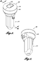
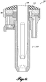
- An exemplary combined probe 100 is pictured in FIGURE 1B and FIGURES 3-6 are line drawings depicting the housing and therapy probe.
- the housing 300 includes a therapy probe transducer 305 a lens 310, an elongate handle 315, and a housing 320 configured to hold an imaging probe, which fits through the lens 310 and therapy transducer 305 via an aperture 311 in each.
- FIGURE 6 is a cross-sectional view of the housing 300.
- the therapy probe transducer 305 is a custom PZT transducer and the imaging probe is a commercial imaging probe.
- both probes are custom made or both are commercially available.
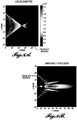
- FIGURES 7A and 7B compare the relative therapy region sizes of a commercial therapy probe ( FIGURE 7A ) compared to the broadly focused therapy probe disclosed herein ( FIGURE 7B ).
- the size of the therapy region can be an order of magnitude larger, which allows for a broader push on a plurality of stones or fragments.
- kidney stones or fragments thereof
- the concepts disclosed herein can also be used to move other embedded objects, including, but not limited to, stones, fragments, blood clots, bullets, mucous, cystic fibrosis mucous, flowing blood, impacted stool in constipation, rectal, urethral and bladder foreign bodies, ureteral stones, bladder stones, airway foreign bodies, nasal congestion, sinus obstruction, impacted cerumen (ear wax), tissue flaps (like a torn retina), or floating objects in the eye and dust located in any of the gall bladder, the salivary tract, biliary tract or any other anatomical location of a human or other mammal.
- An additional use for the disclosed embodiments is to become a part of the maintenance program of implanted foreign bodies to prevent encrustation or occlusion over time.
- ureteral stents become encrusted from urine solutes precipitating over time on the surface of the stent.
- the stent could receive intermittent pushing every 3 weeks to "disrupt" or slow the encrustation process.
- cardiac stents A similar embodiment could be envisioned for cardiac stents.”
- the term "about” indicates that the subject value can be modified by plus or minus 5% and still fall within the disclosed embodiment. Additionally, stated values are in situ.
- the therapy probe is an ultrasonic transducer.
- Ultrasonic transducers are generally known in the art and are formed from piezoelectric materials, such as lead zirconate titanate (PZT).
- the pulses have a duration of 1 ms to 350 ms. In a further embodiment, the pulses have a duration of 10 ms to 200 ms. In yet a further embodiment, the pulses have a duration of 50 ms to 200 ms. An exemplary embodiment utilizes 25 ms pulse durations.
- FIGURE 2 illustrates a therapy exposure 200 comprising a number of pulses 205, 210, 215.
- Each pulse 205 et al. has an on time which is followed by an off time 206 in which the imaging probe can operate to produce at least two frames per second. This frame rate, while low, still allows an operator to track kidney stones exposed to the therapy exposure sufficiently.
- imaging is not used during therapy exposure.
- imaging the therapy region provides significant benefits to use.
- the total time over which the therapy probe operates is referred to as the "therapy exposure time.”
- the duty cycle is defined as the percentage of on time compared to total on time and off time before a new pulse begins.
- the therapy exposure is a single continuous pulse.
- Average power is another characteristic useful for defining the therapy probe and the therapy exposure. Average power is defined as the total power emitted over the active area of the probe averaged over the duration of the therapy exposure.
- the therapy probe is configured to produce an average power of 5 W to 200 W for 1 second to 10 min. In one embodiment, the therapy probe is configured to produce an average power of 10 W to 200 W for 1 second to 10 min. In one embodiment, the therapy probe is configured to produce an average power of 15 W to 60 W for 1 second to 10 min.
- the therapy region is defined by a single therapy pulse.
- the definitions described herein of beam width are for exposure to one focus. This is in contrast to a system that uses a sequence of pulses focused on different points to broaden the total exposed width.
- the width used herein is the width of a beam at a snapshot in time. It is not the width constructed by a succession of pulses.
- the therapy region has a length of 2 cm to 15 cm. In one embodiment, the therapy region has a length of 4 cm to 10 cm. In one embodiment, the therapy region has a length of 3 cm or greater. In one embodiment, the therapy region has a length of 5 cm or greater. In one embodiment, the therapy region has a length of 15 cm or less.
- the therapy region has a width of 2 mm to 20 mm. In one embodiment, the therapy region has a width of 1 mm to 10 mm. In one embodiment, the therapy region has a width of 5 mm to 8 mm. In one embodiment, the therapy region has a width of greater than 3 mm. In one embodiment, the therapy region has a width of greater than 5 mm. In one embodiment, the therapy region has a width of less than 10 mm. In one embodiment, the therapy region has a width of less than 20 mm.
- the therapy region has a width of at least 1 mm and a length of at least 2 cm; In one embodiment, the therapy region has a width of at least 2 mm and a length of at least 1 cm. In one embodiment, the therapy region has a width of at least 1 mm and a length of at least 1 cm.
- the frequency is 200 kHz to 500 kHz. In one embodiment, the frequency is 300 kHz to 450 kHz.
- the peak negative pressure in the therapy region is 1.0 MPa to 4.0 MPa. In one embodiment, the peak negative pressure in the therapy region is 1.5 MPa to 3.5 MPa.
- the therapy region begins at least 1 cm from the therapy probe. In one embodiment, the therapy region begins at least 3 cm from the therapy probe. In one embodiment, the therapy region begins at least 5 cm from the therapy probe.
- the therapy exposure is at least 1 second long. In one embodiment, the therapy exposure is at least 10 seconds long. In one embodiment, the therapy exposure is at least 30 seconds long. In one embodiment, the therapy exposure is at least 60 seconds long. In one embodiment, the therapy exposure is at least 5 minutes long. In one embodiment, the therapy exposure is at least 10 minutes long.
- the therapy exposure comprises a therapy burst that comprises a plurality of pulses separated by off periods. This configuration is illustrated in FIGURE 2 .
- the therapy burst has a duty cycle of greater than 30%. In one embodiment, the therapy burst has a duty cycle of greater than 50%. In one embodiment, the therapy burst has a duty cycle of greater than 75%.
- Mechanical index is defined herein as peak negative pressure (MPa)/square root of frequency (in MHz).
- FIGURE 13 graphically illustrates the correlation between mechanical index (MI), pressure, and frequency of an ultrasound system.
- the mechanical index is 10 or below, which is the upper limit before stone fragmentation is likely occur.
- the mechanical index is 4 or below, which is an FDA limit related to imaging.
- the mechanical index is 1.9 or below, which is a lower FDA limit.
- the therapy probe has a largest aperture dimension (e.g., FIGURE 1A OD ) that is 5 cm or less. In one embodiment, the therapy probe has a largest aperture dimension (e.g., FIGURE 1A OD ) that is 2 cm or greater. In other embodiments, the OD is greater than 5 cm. Accordingly, in one embodiment the OD is less than 10 cm. In yet another embodiment the OD is less than 7 cm.
- the therapy probe has a single ultrasonic therapy element, thereby providing a fixed focus to define the therapy region.
- the therapy probe is annular with a center cavity configured that is acoustically transparent in order to allow the imaging probe to image through the center cavity.
- the therapy probe and the imaging probe are configured to mate together coaxially.
- Coaxial probes are illustrated in FIGURE 1A , disposed along axis A.
- the term "mate" refers to an arrangement where the therapy probe and imaging probe are disposed within the same combined probe, as illustrated in FIGURES 1A and 1B .
- FIGURES 3-6 illustrate a FIGURE 1C illustrates non-coaxial probes, although in such a configuration the therapy probe 105 and imaging probe 110' are still synchronized to provide a therapy exposure and image the therapy region 115.
- the imaging probe can be any imaging probe known to those of skill in the art that is sufficient to image the therapy region and synchronize with the therapy probe.
- the imaging probe 110 or 110' has a height h and a width w. In one embodiment the height is from 1 cm to 2 cm. In one embodiment, the width is from 1 cm to 3 cm.
- the imaging probe and therapy probe are synchronized, such that imaging probe produces an imaging signal during an off period of the therapy exposure between pulses.
- the ultrasonic therapy system further comprises a switch configured to transition the ultrasonic therapy system from an imaging mode, wherein only the imaging probe is activated without the therapy probe, to a therapy mode, wherein the imaging probe and the therapy probe are both activated and synchronized to alternatingly produce an image of the therapy region and apply the therapy exposure to the therapy region.
- the ultrasonic therapy system is further configured to adjust a distance from the therapy probe to the start of the therapy region in response to changing a depth-of-focus of the imaging probe or vice versa.
- the ultrasonic therapy system further includes a lens related to the therapy probe.
- a lens is essentially any material used to couple ultrasound to tissue.
- the lens is flat on the distal surface in one embodiment.
- the lens is convex on the distal surface.
- the lens is concave on the distal surface, thereby having a small cavity that can be filled with a gel or disposable pad.
- the lens is formed from a material selected from the group consisting of plastic, oil, ceramic, alcohol, water based fluid, gel, metal (e.g.. aluminum), graphite, and combinations thereof.
- plastics include siloxanes and urethanes. Particularly beneficial are polymers that can be polymerized at room temperature.
- the lens provides acoustic matching between the therapy probe and a therapy target.
- a matching layer is included in between the transducer and the lens. See, for example, part 615 in FIGURE 12A .
- the matching layer does not provide focusing but instead functions to transition impedance between the transducer and lens. Impedance mismatch will produce acoustic energy noise.
- Representative matching layer materials include composites, such as epoxies loaded with tungsten, aluminum or graphite.
- the ultrasonic therapy system further includes an amplifier configured to drive the therapy probe.
- the amplifier can be off-the-shelf or custom designed to produce the necessary power.
- the amplifier is configured to operate at a voltage (peak-to-peak) of 100 V to 3,000 V.
- the amplifier is configured to operate at a (time average) power of 10 W to 1000 W.
- the amplifier is configured to operate at a (time average) power of 20 W to 1000 W.
- the amplifier is configured to operate at a (time average) power of 20 W to 500 W.
- the ultrasonic therapy system further includes a cooling mechanism configured to remove heat from the therapy probe.
- FIGURES 12A-12D illustrate representative embodiments of probes 600 with incorporated cooling systems.
- the probe 600 includes a transducer 605, a lens 610, and a matching layer 615 between the transducer 605 and lens 610 to provide acoustic matching.
- An inlet and outlet 625 provides liquid or gas access to a cooling cavity 620.
- thermocouple 606 or other temperature measurement component is applied to the transducer 605 ( FIGURE 12A ) or the lens 610 ( FIGURE 12B ), or both (not pictured).
- the thermocouple 606 can be attached to a display in order to provide the operator with a visual indication of the temperature of the transducer 605, in case overheating is a danger, or the lens 610 if burning the patient's skin is a danger.
- the thermocouple can also be interfaced with a CPU or other system component in order to automate the indication of dangerous conditions or provide a feedback signal related to driving the transducer 605 (e.g., if the transducer 605 temperature rises dangerously the system will shut off the transducer 605, activate cooling, and/or warn the operator).
- the cooling cavity 620 is filled with a gas (e.g., air) in one embodiment.
- a gas e.g., air
- the cooling cavity is filled with a liquid (e.g., water).
- the gas or liquid can be circulated through the inlet and outlet 625 to provide improved cooling.
- a heat sink 630 is interfaced with the transducer 605 to remove heat therefrom.
- a plurality of fins of the heat sink 630 extend into the cooling cavity 620 to dissipate heat further.
- the heat sink 630 is instead disposed on the opposite wall of the cooling cavity 620 from the transducer 605.
- a second heat sink 640 (or second portion of the first heat sink 630) is disposed on the outside of the cooling cavity 620 in order to dissipate heat transferred from the transducer 605, to the cooling cavity 620, through the first heat sink 630 and then second heat sink 640).
- FIGURE 12D is yet a further embodiment, which integrates a thermo-electric cooler 650 (TEC or Peltier element) to manage heat transferred from the transducer 605.
- TEC thermo-electric cooler
- the cooling mechanism is selected from the group consisting of air cooling, liquid cooling, a heat sink, a heat pipe, a thermo-electric cooler, and combinations thereof.
- the cooling mechanism is configured to remove heat from a portion of the therapy probe selected from the group consisting of a lens and an ultrasonic therapy element.
- CPU Central Processing Unit
- the ultrasonic therapy system further includes a central processing unit (CPU) and a user interface, wherein the therapy probe, the imaging probe, and the user interface are each operatively connected through the CPU, and wherein the CPU is configured to control ultrasonic exposure from the therapy probe according to the user interface.
- the CPU can be any CPU known to those of skill in the art, such as a personal computer.
- the CPU may be used to coordinate the activities of the various system components (e.g., probes, amplifier, imaging), as described in more detail below with reference to FIGURE 14 .
- the imaging probe is configured to produce an ultrasound image of the therapy region on the user interface and wherein the imaging probe is synchronized with the therapy probe to obtain images of the therapy region in between pulses from the therapy probe.
- the CPU is configured to change the location or size of the therapy region via the therapy probe in response to input through the user interface.
- FIGURE 14 schematically illustrates an "expanded" system 700 that includes many of the components already disclosed.
- a combined probe 701 includes a therapy probe 705 and an imaging probe 710 imbedded therein.
- a therapy region 715 is illustrated as containing a plurality of targets (e.g., kidney stones).
- a CPU/amplifier 717 ultimately drives the therapy probe 705 and coordinates with the ultrasound imaging system 730 to coordinate the imaging probe 710 and therapy probe 705.
- the CPU and amplifier may be split into different components or may be combined in a single unit.
- the amplifier 717 can be activated by several mechanisms, with the mechanism in FIGURE 14 being a foot pedal 720. During operation, a user presses a foot pedal 720 to activate the therapy exposure via the amplifier 717 and therapy probe 705. Use of the foot pedal 720 allows the user hands-free activation of the system 700. When the foot is removed from the pedal 720 the therapy exposure ceases. A number of pulses are emitted from the therapy probe 705 during the therapy exposure.
- the amplifier 717 powers the therapy probe 705 via a matching network 725 that provides the appropriate power characteristics to the therapy probe 705 to generate the desired signal.
- the imaging probe 710 provides imaging via an ultrasound imaging system 730 of the type known to those of skill in the art. Coordination with the amplifier 717 is made via a synchronization 735 bridge and setting and controls are coordinate 740 (e.g., by USB).
- An optional cooling system 745 can be activated to cool the combined probe 701 and may receive input from a temperature sensor (e.g., a thermocouple).
- the cooling system 745 may interface with the CPU/amplifier 717 to shut off or reduce use of the therapy probe 705 if the temperature reaches a set limit.
- the sensor may be used to active the cooling system 745 to cool the therapy probe 705.
- a combined probe in another aspect, is provided according to the embodiments shown and described.
- the probe includes a therapy probe and at least a cavity in which to coaxially dispose an imaging probe.
- the combined probe includes the imaging probe disposed within the cavity.
- the combined probe can be interfaced with an amplifier and imaging system as disclosed herein and can be used to perform the methods disclosed herein.
- An exemplary method of moving one or more target objects using ultrasonic propulsion includes applying a non-lithotriptic acoustic radiation force to a target object using an ultrasonic therapy system as shown and described herein. While the disclosed embodiments are primarily described in the context of moving kidney stones, it will be appreciated that the systems can be applied to move any small object within the appropriate range from the therapy probe. The target need not be in a living being.
- the target object is at least one in vivo kidney stone.
- the systems can be applied to patients in need in any manner useful to one of skill in the art.
- the systems are designed to ease the movement and eventual removal of kidney stones or fragments from the body. Therefore, the disclosed methods utilize the disclosed systems for moving one or more kidney stones.
- At least one the kidney stone is within a patient in an area selected from the group consisting of a kidney, a uretropelvic junction (UPJ), a bladder, a ureterovesicle junction (UVJ), and a ureter.
- UPJ uretropelvic junction
- bladder a bladder
- UVJ ureterovesicle junction
- ureter a ureterovesicle junction
- the at least one kidney stone is moved a distance of at least 3 mm. This is a significant distance within a patient and indicates the broad moving effect of the systems and methods.
- a plurality of kidney stones are simultaneously moved a distance of at least 3 mm.
- the at least one kidney stone is a plurality of kidney stones and wherein the plurality of kidney stones are moved a distance of at least 3 mm during the therapy exposure time.
- a method of moving one or more kidney stones in a therapy region using ultrasonic propulsion includes using a broadly focused ultrasound therapy probe to apply a force on one or more kidney stones having a diameter of from 0.5 mm to 20 mm disposed within the therapy region, wherein the acoustic radiation force applied to each of the one or more kidney stones is from 50 ⁇ N to 0.5 N, and wherein the acoustic radiation force is not sufficient to fragment the kidney stones.
- This aspect is not necessarily tied to the exact devices disclosed herein, although such devices and systems are compatible with the present method. However, the present aspect at its most basic level is directed to use of broadly focused ultrasound to apply pressure to kidneys stones.
- an imaging probe is synchronized with the therapy probe. This method is compatible with all of the systems, device, and methods disclosed elsewhere herein.
- the shift from a prior art 128-element, 2-MHz imaging/pushing probe to a single element, low frequency (300 kHz) therapy probe enables displacing an entire cluster of stones.
- the imbedded imaging probe allows the user to observe fragment and cluster displacement while effectively sweeping a region stone free.
- the overall footprint diameter is 5 cm or less. This size factor is important when considering the usability of the probe in a clinical context. First, the probe must be easily hand held and operable with one hand. Second the probe must be small enough to apply to a patient at several different points on the body, which requires a small probe that can mate with any skin surface.
- FIGURE 1B An exemplary combined probe is pictured in FIGURE 1B , with this model referred having a convex hole and a relatively large (about 1x2 cm) imaging probe.
- the annular therapy probe is typically driven at 400 KHz.
- the annular, single element therapy transducer can be seen around the perimeter and the central feature is the imbedded imaging probe.
- Propulse-2R is as follows: hand held, off the shelf P4-2 Philips phased array imaging probe that is removable from the central cavity of the probe; therapy probe is about 5 cm in diameter; imaging probe is coaxial; imbedded thermocouple on the therapy probe transducer; convex RTV (room temperature vulcanization) lens; and no cooling system.
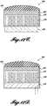
- FIGURE 1D Another exemplary combined probe includes a single element therapy transducer with an imaging probe on the side, as illustrated in FIGURE 1C and pictured in FIGURE 1D .
- the exemplary probe of FIGURE 1D includes a concave aluminum lens, a 3D printed housing with a concave lens with water coupling, a second lens that is concave formed from RTV silicon.
- Certain prototypes included a metal lens, cooling system, with and without latex, and a concave lens.
- a system was fabricated wherein the imager and therapy probes were connected but not concentric.
- Redesigned imaging probes to make them flatter to have a farther focus, to lower the frequency, and to have better cooling.
- FIGURES 8A and 8B are graphical depictions of simulation data relating to a prior art therapy probe ( FIGURE 8A ) and an exemplary probe ( FIGURE 8B ).
- the simulation data were generated using the FOCUS ultrasound simulator from Michigan State University.
- Comparative FIGURE 8A is a 128 element transducer operating at 2.4 MHz while exemplary FIGURE 8B is a single transducer element operating at 400 kHz and dimensions of inner diameter 3 cm, outer diameter 5 cm, and geometric focus of 5 cm.
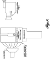
- FIGURES 9-11 relate to experimental testing to determine the "stone pushing" efficacy of the therapy probes (sometimes referred to herein as "LFP" or low-frequency pusher probes) according to the disclosed embodiments and compare them to prior art therapy probes.
- LFP therapy probes
- FIGURE 9 an experimental design according to FIGURE 9 was employed. Specifically, simulated kidney stones were pushed by a transducer while recording the "pushing" of the stones using a digital camera and subsequent image analysis.
- the stone fragments were created using BEGO simulated kidney stone material cement in 1 cm tall x 6 mm diameter cylindrical molds.
- the hardened model stones were crushed into fragments and sieved into groups of 3-4 mm , 2-3 mm, 1-2 mm, and ⁇ 1 mm, each having a sum mass of 80 mg.
- Each group was placed into a pipette and filled with distilled and degased water.
- Each pipette was placed vertical in a holder with a 5 cm phantom between the transducer and stones.
- the phantom (IEC 60601-2-37) simulated human tissue with attenuation approximately 0.5 dB/cm/MHz and sound speed near 1540 cm/s.
- a video camera was used to record the stone motion at approximately 60 fps.
- the exemplary LFP probe was operated at 350 kHz. Both the Propulse-I system (clinical system with the C5-2 diagnostic probe, 128 elements activated, dithered focal volume) and 40 element configuration (C5-2 diagnostic probe with 40 elements activated with no dithering) were operated at their maximum output power. The low frequency probe was tested at 1.1 MPa and 2.4 MPa and 100 ms and 200 ms. Each video frame was processed using two different methods. One method segmented all fragments separately, measured the height of the center of the fragments, and estimated the total volume of the fragment based upon the segmented cross-sectional area.
- the height was multiplied by the volume and summed for all segmented fragments in the field of view. This summed value is the metric for this method. This method does well for all methods where the fragments are >1 mm, but cannot segment the small pieces effectively.
- the second method simply thresholds the image appropriately, and takes a summation of all the resulting pixels scaled by their height.
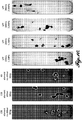
- FIGURE 10 compiles still images at the endpoint (maximum pushed distance) of a test run for each of the transducers tested.
- the transducers were all tested using the same simulated kidney stones and related environment.
- FIGURE 11 summarizes data for 10 sample runs of the type illustrated in FIGURE 10 , in order to numerically characterize the efficacy of the transducers.
- the Y-axis relates to Relative Push Amount, which is calculated by averaging 10 push runs. It is the sum of the heights of the dark pixels (pixels related to stone) and standard deviation error bars.
- the LFP transducers according to the disclosed embodiments provided significantly superior pushing force on the stones.
- the unusual and unexpected efficacy of the inventive transducers compared to the prior art is apparent when viewing FIGURE 11
Claims (15)
- Ultraschall-Therapiesystem (10), das konfiguriert ist, eine nichtlithotriptische akustische Strahlungskraft anzuwenden, um einen Nierenstein zu bewegen, wobei das System Folgendes umfasst:eine Therapiesonde, die konfiguriert ist, Ultraschallexposition, die auf eine Therapieregion gerichtet ist, zu erzeugen, wobei die Therapiesonde ein UltraschallWandler ist;eine Bildgebungssonde, die konfiguriert ist, die Therapieregion durch Ultraschall abzubilden;eine Linse im Zusammenhang mit der Therapiesonde; undeine Anpassungsschicht zwischen dem Wandler und der Linse, um Impedanz zwischen dem Wandler und der Linse umzustellen;wobei die Therapiesonde konfiguriert ist, eine Therapieexposition, umfassend einen oder mehrere Therapieimpulse über eine Therapieexpositionszeit, zu produzieren, wobei die Therapieexposition die folgenden Merkmale aufweist:eine Frequenz von 100 kHz bis 1 MHz;Therapieexpositionszeit von mindestens 10 ms;einen Spitzenunterdruck in der Therapieregion von 0,5 MPa bis 5 MPa;wobei die Therapieregion von einem Impuls ein Volumen definiert, das einem halbmaximalen Druck voller Breite oder größer unterzogen wird, und wobei die Therapieregion eine Länge von 2 cm oder größer in einer axialen Richtung und 2 mm oder mehr in der Breite aufweist; unddie Therapieregion ausreichend ist, um eine akustische Strahlungskraft auf einen Nierenstein mit einem Durchmesser von 0,5 mm bis 20 mm, der in der Therapieregion angeordnet ist, auszuüben, wobei die akustische Strahlungskraft, die auf den Nierenstein angewendet wird, von 50 µN bis 0,5 N ist und wobei die akustische Strahlungskraft nicht ausreichend ist, um den Nierenstein zu fragmentieren.
- Ultraschall-Therapiesystem (10) nach Anspruch 1, wobei die Therapiesonde konfiguriert ist, eine mittlere Leistung von 10 W bis 200 W für 1 Sekunde bis 10 min zu produzieren.
- Ultraschall-Therapiesystem (10) nach Anspruch 1, wobei die Therapieexposition ein einzelner kontinuierlicher Impuls ist.
- Ultraschall-Therapiesystem nach Anspruch 1, wobei die Therapieexposition einen Therapiestoß umfasst, der eine Vielzahl von Impulsen, die durch Aus-Perioden getrennt sind, umfasst.
- Ultraschall-Therapiesystem nach Anspruch 1, wobei die Therapiesonde eine größte Öffnungsbemaßung aufweist, die 5 cm oder weniger ist.
- Ultraschallsystem nach Anspruch 1, wobei die Therapiesonde ein einzelnes Ultraschall-Therapieelement aufweist, wodurch ein Fixfokus bereitgestellt wird, um die Therapieregion zu definieren.
- Ultraschall-Therapiesystem nach Anspruch 1, wobei die Therapiesonde ringförmig mit einem zentralen Hohlraum ist, der konfiguriert ist, der akustisch transparent ist, um der Bildgebungssonde zu ermöglichen, durch den zentralen Hohlraum abzubilden.
- Ultraschall-Therapiesystem nach Anspruch 1, wobei die Therapiesonde und die Bildgebungssonde konfiguriert sind, koaxial zusammenzupassen.
- Ultraschall-Therapiesystem nach Anspruch 1, wobei die Bildgebungssonde und die Therapiesonde derart synchronisiert sind, dass eine Bildgebungssonde ein Bildgebungssignal während einer Aus-Periode der Therapieexposition zwischen Impulsen produziert,
wobei das Ultraschall-Therapiesystem optional:ferner einen Schalter umfasst, der konfiguriert ist, das Ultraschall-Therapiesystem von einem Bildgebungsmodus, wobei nur die Bildgebungssonde ohne die Therapiesonde aktiviert ist, zu einem Therapiemodus umzustellen, wobei sowohl die Bildgebungssonde als auch die Therapiesonde aktiviert und synchronisiert sind, um abwechselnd ein Bild der Therapieregion zu produzieren und die Therapieexposition auf die Therapieregion anzuwenden; oderferner konfiguriert ist, einen Abstand von der Therapiesonde zu dem Anfang der Therapieregion als Reaktion auf ein Ändern einer Tiefenschärfe der Bildgebungssonde oder umgekehrt einzustellen. - Ultraschall-Therapiesystem nach Anspruch 1, wobei die Linse ein akustisches Anpassen zwischen der Therapiesonde und einem Therapieziel bereitstellt.
- Ultraschall-Therapiesystem nach Anspruch 1, ferner umfassend einen Verstärker, der zum Antreiben der Therapiesonde konfiguriert ist.
- Ultraschall-Therapiesystem nach Anspruch 1, ferner umfassend einen Kühlmechanismus, der konfiguriert ist, Wärme aus der Therapiesonde zu entfernen,
optional wobei der Kühlmechanismus konfiguriert ist, Wärme aus einem Abschnitt der Therapiesonde, ausgewählt aus der Gruppe bestehend aus einer Linse und einem Ultraschall-Therapieelement, zu entfernen. - Ultraschall-Therapiesystem nach Anspruch 1, ferner umfassend eine zentrale Verarbeitungseinheit (central processing unit, CPU) und eine Benutzeroberfläche, wobei die Therapiesonde, die Bildgebungssonde und die Benutzeroberfläche jeweils durch die CPU wirkverbunden sind und wobei die CPU konfiguriert ist, Ultraschallexposition von der Therapiesonde gemäß der Benutzeroberfläche zu steuern.
- Ultraschall-Therapiesystem nach Anspruch 13, wobei die Bildgebungssonde konfiguriert ist, ein Ultraschallbild der Therapieregion auf der Benutzeroberfläche zu produzieren und wobei die Bildgebungssonde mit der Therapiesonde synchronisiert ist, um Bilder der Therapieregion zwischen Impulsen von der Therapiesonde zu erhalten.
- Ultraschall-Therapiesystem nach Anspruch 13, wobei die CPU konfiguriert ist, den Ort oder die Größe der Therapieregion über die Therapiesonde als Reaktion auf eine Eingabe durch die Benutzeroberfläche zu ändern.
Applications Claiming Priority (3)
| Application Number | Priority Date | Filing Date | Title |
|---|---|---|---|
| US201462065432P | 2014-10-17 | 2014-10-17 | |
| US201562160458P | 2015-05-12 | 2015-05-12 | |
| PCT/US2015/056261 WO2016061587A1 (en) | 2014-10-17 | 2015-10-19 | Broadly focused ultrasonic propulsion probes, systems, and methods |
Publications (3)
| Publication Number | Publication Date |
|---|---|
| EP3206597A1 EP3206597A1 (de) | 2017-08-23 |
| EP3206597A4 EP3206597A4 (de) | 2018-07-11 |
| EP3206597B1 true EP3206597B1 (de) | 2019-04-24 |
Family
ID=55747490
Family Applications (1)
| Application Number | Title | Priority Date | Filing Date |
|---|---|---|---|
| EP15851498.4A Active EP3206597B1 (de) | 2014-10-17 | 2015-10-19 | Sonden, systeme für breit gebündelten ultraschallantrieb |
Country Status (5)
| Country | Link |
|---|---|
| US (1) | US10667831B2 (de) |
| EP (1) | EP3206597B1 (de) |
| JP (1) | JP6412275B2 (de) |
| CN (1) | CN107106191B (de) |
| WO (1) | WO2016061587A1 (de) |
Families Citing this family (4)
| Publication number | Priority date | Publication date | Assignee | Title |
|---|---|---|---|---|
| US20200022714A1 (en) | 2016-10-18 | 2020-01-23 | SonoMotions Inc. | Ultrasound devices incorporating phase change materials and systems and methods using the devices |
| US11026706B1 (en) | 2016-11-18 | 2021-06-08 | University Of Washington | Modulation of transducer amplitude and phase distributions for controlled application of radiation force to an object |
| KR102059390B1 (ko) | 2018-03-30 | 2019-12-26 | 주식회사 에이치엔티메디칼 | 체외 충격파 쇄석기에 설치되는 초음파 거리 측정 장치 |
| WO2020037041A1 (en) * | 2018-08-16 | 2020-02-20 | University Of Washington | Apparatus and method for ultrasound beam shaping |
Family Cites Families (37)
| Publication number | Priority date | Publication date | Assignee | Title |
|---|---|---|---|---|
| DE4132343C1 (de) * | 1991-09-27 | 1992-12-10 | Siemens Ag, 8000 Muenchen, De | |
| US5743862A (en) * | 1994-09-19 | 1998-04-28 | Kabushiki Kaisha Toshiba | Ultrasonic medical treatment apparatus |
| JP3993621B2 (ja) * | 1995-03-31 | 2007-10-17 | 株式会社東芝 | 超音波治療装置 |
| US5558092A (en) * | 1995-06-06 | 1996-09-24 | Imarx Pharmaceutical Corp. | Methods and apparatus for performing diagnostic and therapeutic ultrasound simultaneously |
| US20010051131A1 (en) * | 1996-06-19 | 2001-12-13 | Evan C. Unger | Methods for delivering bioactive agents |
| US20030078227A1 (en) * | 1998-07-02 | 2003-04-24 | Greenleaf James F. | Site-directed transfection with ultrasound and cavitation nuclei |
| US7022077B2 (en) * | 2000-11-28 | 2006-04-04 | Allez Physionix Ltd. | Systems and methods for making noninvasive assessments of cardiac tissue and parameters |
| CA2490999A1 (en) * | 2002-07-01 | 2004-01-08 | Allez Physionix Limited | Systems and methods for making noninvasive assessments of cardiac tissue and parameters |
| US20050228284A1 (en) * | 2004-03-31 | 2005-10-13 | Charles Edward Baumgartner | System and method for power management in an ultrasound system |
| JP5179058B2 (ja) * | 2004-10-15 | 2013-04-10 | 株式会社日立メディコ | 超音波診断装置 |
| US7591996B2 (en) * | 2005-08-17 | 2009-09-22 | University Of Washington | Ultrasound target vessel occlusion using microbubbles |
| US7967763B2 (en) * | 2005-09-07 | 2011-06-28 | Cabochon Aesthetics, Inc. | Method for treating subcutaneous tissues |
| US8057408B2 (en) * | 2005-09-22 | 2011-11-15 | The Regents Of The University Of Michigan | Pulsed cavitational ultrasound therapy |
| US10219815B2 (en) * | 2005-09-22 | 2019-03-05 | The Regents Of The University Of Michigan | Histotripsy for thrombolysis |
| US8939911B2 (en) * | 2006-01-25 | 2015-01-27 | Kabushiki Kaisha Toshiba | Ultrasonic probe and apparatus for obtaining ultrasonic image |
| US7486405B2 (en) * | 2006-05-01 | 2009-02-03 | Hogan Josh N | Optimized reference level generation |
| US8535250B2 (en) * | 2006-10-13 | 2013-09-17 | University Of Washington Through Its Center For Commercialization | Method and apparatus to detect the fragmentation of kidney stones by measuring acoustic scatter |
| US20080195003A1 (en) * | 2007-02-08 | 2008-08-14 | Sliwa John W | High intensity focused ultrasound transducer with acoustic lens |
| US20080312581A1 (en) * | 2007-06-06 | 2008-12-18 | Biovaluation & Analysis, Inc. | Peptosomes for Use in Acoustically Mediated Intracellular Drug Delivery in vivo |
| US20090230823A1 (en) * | 2008-03-13 | 2009-09-17 | Leonid Kushculey | Operation of patterned ultrasonic transducers |
| US9987505B2 (en) * | 2008-08-20 | 2018-06-05 | The Brigham And Women's Hospital, Inc. | Method for modifying glomerular permeability and function with focused ultrasound |
| US20100143241A1 (en) * | 2008-10-22 | 2010-06-10 | Johnson G Allan | Method and apparatus for delivery of agents across the blood brain barrier |
| EP2243561B1 (de) * | 2009-04-23 | 2018-11-28 | Esaote S.p.A. | Array von elektroakustischen Wandlern und elektronische Sonde für dreidimensionale Bilder, die das Wandlerarray umfasst |
| WO2011033277A2 (en) * | 2009-09-21 | 2011-03-24 | University Of Dundee | Apparatus and method for the manipulation of objects using ultrasound |
| JP5399192B2 (ja) * | 2009-09-30 | 2014-01-29 | 富士フイルム株式会社 | 超音波診断装置、および超音波診断装置の作動方法 |
| US8876740B2 (en) * | 2010-04-12 | 2014-11-04 | University Of Washington | Methods and systems for non-invasive treatment of tissue using high intensity focused ultrasound therapy |
| EP2560553B1 (de) | 2010-04-22 | 2019-10-30 | University of Washington through its Center for Commercialization | Ultraschallbasierte vorrichtung zur entfernung von steinen |
| WO2011153268A2 (en) * | 2010-06-01 | 2011-12-08 | The Trustees Of Columbia University In The City Of New York | Devices, methods, and systems for measuring elastic properties of biological tissues |
| US8455989B2 (en) | 2011-07-01 | 2013-06-04 | Texas Instruments Incorporated | Package substrate having die pad with outer raised portion and interior recessed portion |
| CN103028203B (zh) * | 2011-10-09 | 2016-08-31 | 北京汇福康医疗技术股份有限公司 | 超声减脂治疗头及其工作方法 |
| US9096848B2 (en) * | 2011-11-10 | 2015-08-04 | Technion Research & Development Foundation Limited | Methods and devices for manipulation of target cells using a combined application of acoustical and optical radiations |
| WO2013102072A1 (en) * | 2011-12-28 | 2013-07-04 | Boston Scientific Scimed, Inc. | Ablation probe with ultrasonic imaging capability |
| EP2628456B1 (de) * | 2012-02-15 | 2015-08-12 | Dornier Med Tech Systems GmbH | Stoßwellentherapievorrichtung mit dynamischer Zielnachführung |
| US9072879B2 (en) * | 2012-03-29 | 2015-07-07 | National Yang Ming University | Methods and system for ultrasound-mediated drug delivery |
| WO2014008408A1 (en) * | 2012-07-03 | 2014-01-09 | University Of Pittsburgh - Of The Commonwealth System Of Higher Education | Method and apparatus to detect lipid contents in tissues using ultrasound |
| CA2878491A1 (en) * | 2012-07-08 | 2014-01-16 | Sunnybrook Health Sciences Centre | System and method for using ultrasound-stimulated microbubble exposures to induce ceramide accumulation in endothelial and tumor cells |
| WO2015070186A1 (en) * | 2013-11-08 | 2015-05-14 | The University Of North Carolina At Chapel Hill | Acoustic detection of activated phase-change contrast agent |
-
2015
- 2015-10-19 EP EP15851498.4A patent/EP3206597B1/de active Active
- 2015-10-19 CN CN201580061007.7A patent/CN107106191B/zh active Active
- 2015-10-19 WO PCT/US2015/056261 patent/WO2016061587A1/en active Application Filing
- 2015-10-19 US US15/519,821 patent/US10667831B2/en active Active
- 2015-10-19 JP JP2017539527A patent/JP6412275B2/ja active Active
Non-Patent Citations (1)
| Title |
|---|
| None * |
Also Published As
| Publication number | Publication date |
|---|---|
| JP6412275B2 (ja) | 2018-10-24 |
| WO2016061587A1 (en) | 2016-04-21 |
| US20170245874A1 (en) | 2017-08-31 |
| US10667831B2 (en) | 2020-06-02 |
| CN107106191B (zh) | 2019-08-23 |
| EP3206597A1 (de) | 2017-08-23 |
| JP2017532177A (ja) | 2017-11-02 |
| EP3206597A4 (de) | 2018-07-11 |
| CN107106191A (zh) | 2017-08-29 |
Similar Documents
| Publication | Publication Date | Title |
|---|---|---|
| EP3206597B1 (de) | Sonden, systeme für breit gebündelten ultraschallantrieb | |
| CN109890463B (zh) | 用于皮肤处理的声学装置 | |
| Ter Haar | HIFU tissue ablation: concept and devices | |
| JP6068503B2 (ja) | ヒストトリプシ治療用変換器 | |
| JP5863654B2 (ja) | 治療および画像処理超音波変換器用のマイクロマニピュレータ制御アーム | |
| ES2699477T3 (es) | Métodos y sistemas para acoplar y enfocar energía acústica usando un miembro acoplador | |
| JP2008513149A (ja) | トランスデューサを冷却するための循環と共に独立した水クッションを用いた音響カプラ | |
| Kim et al. | Lesion generation through ribs using histotripsy therapy without aberration correction | |
| KR101052060B1 (ko) | 집속 초음파 생성 장치 | |
| Bailey et al. | Update on clinical trials of kidney stone repositioning and preclinical results of stone breaking with one system | |
| CN101166471A (zh) | 具有可操作的指示器组件的超声探头 | |
| JP2017532177A5 (de) | ||
| JP2009233247A (ja) | 超音波検査システム及び画像処理装置 | |
| Janssen et al. | Safety and effectiveness of a longer focal beam and burst duration in ultrasonic propulsion for repositioning urinary stones and fragments | |
| JP4139916B2 (ja) | 超音波照射方法及び超音波照射装置 | |
| KR101861842B1 (ko) | 복수의 주파수를 이용한 고강도 집속 초음파 제어방법과 그를 위한 고강도 집속 초음파 치료 장치 | |
| Maxwell et al. | A tissue phantom for evaluation of mechanical damage caused by cavitation | |
| KR101585301B1 (ko) | 집중초음파를 생체조직에 투과하기 위해 반고체 수화젤을 이용한 장치 및 그 제조방법 | |
| KR20120012931A (ko) | 집속 초음파 생성 장치 | |
| Ryu | Optoacoustic Instrument Systems–A Mini | |
| Randad | Design, Fabrication and Characterization of Ultrasound Transducers for Fragmenting Large Renal Calculi | |
| KR20230099728A (ko) | 초점의 전기적 스티어링을 수행하는 트랜스듀서 | |
| Erpelding et al. | Spatially mapping the elastic properties of the lens using bubble-based acoustic radiation force | |
| JPH04336060A (ja) | 超音波治療装置 | |
| Worthington et al. | A comparison of imaging modalities to monitor thermal and mechanical ultrasound tissue therapies |
Legal Events
| Date | Code | Title | Description |
|---|---|---|---|
| STAA | Information on the status of an ep patent application or granted ep patent |
Free format text: STATUS: THE INTERNATIONAL PUBLICATION HAS BEEN MADE |
|
| PUAI | Public reference made under article 153(3) epc to a published international application that has entered the european phase |
Free format text: ORIGINAL CODE: 0009012 |
|
| STAA | Information on the status of an ep patent application or granted ep patent |
Free format text: STATUS: REQUEST FOR EXAMINATION WAS MADE |
|
| 17P | Request for examination filed |
Effective date: 20170404 |
|
| AK | Designated contracting states |
Kind code of ref document: A1 Designated state(s): AL AT BE BG CH CY CZ DE DK EE ES FI FR GB GR HR HU IE IS IT LI LT LU LV MC MK MT NL NO PL PT RO RS SE SI SK SM TR |
|
| AX | Request for extension of the european patent |
Extension state: BA ME |
|
| DAV | Request for validation of the european patent (deleted) | ||
| DAX | Request for extension of the european patent (deleted) | ||
| A4 | Supplementary search report drawn up and despatched |
Effective date: 20180607 |
|
| RIC1 | Information provided on ipc code assigned before grant |
Ipc: A61B 17/22 20060101AFI20180601BHEP |
|
| REG | Reference to a national code |
Ref country code: DE Ref legal event code: R079 Ref document number: 602015029091 Country of ref document: DE Free format text: PREVIOUS MAIN CLASS: A61B0017220000 Ipc: A61N0007020000 |
|
| RIC1 | Information provided on ipc code assigned before grant |
Ipc: A61N 7/02 20060101AFI20181004BHEP Ipc: A61B 17/225 20060101ALI20181004BHEP |
|
| GRAP | Despatch of communication of intention to grant a patent |
Free format text: ORIGINAL CODE: EPIDOSNIGR1 |
|
| STAA | Information on the status of an ep patent application or granted ep patent |
Free format text: STATUS: GRANT OF PATENT IS INTENDED |
|
| INTG | Intention to grant announced |
Effective date: 20181210 |
|
| GRAS | Grant fee paid |
Free format text: ORIGINAL CODE: EPIDOSNIGR3 |
|
| GRAA | (expected) grant |
Free format text: ORIGINAL CODE: 0009210 |
|
| STAA | Information on the status of an ep patent application or granted ep patent |
Free format text: STATUS: THE PATENT HAS BEEN GRANTED |
|
| AK | Designated contracting states |
Kind code of ref document: B1 Designated state(s): AL AT BE BG CH CY CZ DE DK EE ES FI FR GB GR HR HU IE IS IT LI LT LU LV MC MK MT NL NO PL PT RO RS SE SI SK SM TR |
|
| REG | Reference to a national code |
Ref country code: GB Ref legal event code: FG4D |
|
| REG | Reference to a national code |
Ref country code: CH Ref legal event code: EP |
|
| REG | Reference to a national code |
Ref country code: AT Ref legal event code: REF Ref document number: 1123417 Country of ref document: AT Kind code of ref document: T Effective date: 20190515 Ref country code: IE Ref legal event code: FG4D |
|
| REG | Reference to a national code |
Ref country code: DE Ref legal event code: R096 Ref document number: 602015029091 Country of ref document: DE |
|
| REG | Reference to a national code |
Ref country code: NL Ref legal event code: MP Effective date: 20190424 |
|
| REG | Reference to a national code |
Ref country code: LT Ref legal event code: MG4D |
|
| PG25 | Lapsed in a contracting state [announced via postgrant information from national office to epo] |
Ref country code: NL Free format text: LAPSE BECAUSE OF FAILURE TO SUBMIT A TRANSLATION OF THE DESCRIPTION OR TO PAY THE FEE WITHIN THE PRESCRIBED TIME-LIMIT Effective date: 20190424 |
|
| PG25 | Lapsed in a contracting state [announced via postgrant information from national office to epo] |
Ref country code: PT Free format text: LAPSE BECAUSE OF FAILURE TO SUBMIT A TRANSLATION OF THE DESCRIPTION OR TO PAY THE FEE WITHIN THE PRESCRIBED TIME-LIMIT Effective date: 20190824 Ref country code: AL Free format text: LAPSE BECAUSE OF FAILURE TO SUBMIT A TRANSLATION OF THE DESCRIPTION OR TO PAY THE FEE WITHIN THE PRESCRIBED TIME-LIMIT Effective date: 20190424 Ref country code: SE Free format text: LAPSE BECAUSE OF FAILURE TO SUBMIT A TRANSLATION OF THE DESCRIPTION OR TO PAY THE FEE WITHIN THE PRESCRIBED TIME-LIMIT Effective date: 20190424 Ref country code: NO Free format text: LAPSE BECAUSE OF FAILURE TO SUBMIT A TRANSLATION OF THE DESCRIPTION OR TO PAY THE FEE WITHIN THE PRESCRIBED TIME-LIMIT Effective date: 20190724 Ref country code: FI Free format text: LAPSE BECAUSE OF FAILURE TO SUBMIT A TRANSLATION OF THE DESCRIPTION OR TO PAY THE FEE WITHIN THE PRESCRIBED TIME-LIMIT Effective date: 20190424 Ref country code: HR Free format text: LAPSE BECAUSE OF FAILURE TO SUBMIT A TRANSLATION OF THE DESCRIPTION OR TO PAY THE FEE WITHIN THE PRESCRIBED TIME-LIMIT Effective date: 20190424 Ref country code: LT Free format text: LAPSE BECAUSE OF FAILURE TO SUBMIT A TRANSLATION OF THE DESCRIPTION OR TO PAY THE FEE WITHIN THE PRESCRIBED TIME-LIMIT Effective date: 20190424 |
|
| PG25 | Lapsed in a contracting state [announced via postgrant information from national office to epo] |
Ref country code: RS Free format text: LAPSE BECAUSE OF FAILURE TO SUBMIT A TRANSLATION OF THE DESCRIPTION OR TO PAY THE FEE WITHIN THE PRESCRIBED TIME-LIMIT Effective date: 20190424 Ref country code: PL Free format text: LAPSE BECAUSE OF FAILURE TO SUBMIT A TRANSLATION OF THE DESCRIPTION OR TO PAY THE FEE WITHIN THE PRESCRIBED TIME-LIMIT Effective date: 20190424 Ref country code: BG Free format text: LAPSE BECAUSE OF FAILURE TO SUBMIT A TRANSLATION OF THE DESCRIPTION OR TO PAY THE FEE WITHIN THE PRESCRIBED TIME-LIMIT Effective date: 20190724 Ref country code: GR Free format text: LAPSE BECAUSE OF FAILURE TO SUBMIT A TRANSLATION OF THE DESCRIPTION OR TO PAY THE FEE WITHIN THE PRESCRIBED TIME-LIMIT Effective date: 20190725 Ref country code: LV Free format text: LAPSE BECAUSE OF FAILURE TO SUBMIT A TRANSLATION OF THE DESCRIPTION OR TO PAY THE FEE WITHIN THE PRESCRIBED TIME-LIMIT Effective date: 20190424 |
|
| REG | Reference to a national code |
Ref country code: AT Ref legal event code: MK05 Ref document number: 1123417 Country of ref document: AT Kind code of ref document: T Effective date: 20190424 |
|
| PG25 | Lapsed in a contracting state [announced via postgrant information from national office to epo] |
Ref country code: IS Free format text: LAPSE BECAUSE OF FAILURE TO SUBMIT A TRANSLATION OF THE DESCRIPTION OR TO PAY THE FEE WITHIN THE PRESCRIBED TIME-LIMIT Effective date: 20190824 |
|
| REG | Reference to a national code |
Ref country code: DE Ref legal event code: R097 Ref document number: 602015029091 Country of ref document: DE |
|
| PG25 | Lapsed in a contracting state [announced via postgrant information from national office to epo] |
Ref country code: DK Free format text: LAPSE BECAUSE OF FAILURE TO SUBMIT A TRANSLATION OF THE DESCRIPTION OR TO PAY THE FEE WITHIN THE PRESCRIBED TIME-LIMIT Effective date: 20190424 Ref country code: EE Free format text: LAPSE BECAUSE OF FAILURE TO SUBMIT A TRANSLATION OF THE DESCRIPTION OR TO PAY THE FEE WITHIN THE PRESCRIBED TIME-LIMIT Effective date: 20190424 Ref country code: CZ Free format text: LAPSE BECAUSE OF FAILURE TO SUBMIT A TRANSLATION OF THE DESCRIPTION OR TO PAY THE FEE WITHIN THE PRESCRIBED TIME-LIMIT Effective date: 20190424 Ref country code: AT Free format text: LAPSE BECAUSE OF FAILURE TO SUBMIT A TRANSLATION OF THE DESCRIPTION OR TO PAY THE FEE WITHIN THE PRESCRIBED TIME-LIMIT Effective date: 20190424 Ref country code: SK Free format text: LAPSE BECAUSE OF FAILURE TO SUBMIT A TRANSLATION OF THE DESCRIPTION OR TO PAY THE FEE WITHIN THE PRESCRIBED TIME-LIMIT Effective date: 20190424 Ref country code: RO Free format text: LAPSE BECAUSE OF FAILURE TO SUBMIT A TRANSLATION OF THE DESCRIPTION OR TO PAY THE FEE WITHIN THE PRESCRIBED TIME-LIMIT Effective date: 20190424 |
|
| PG25 | Lapsed in a contracting state [announced via postgrant information from national office to epo] |
Ref country code: SM Free format text: LAPSE BECAUSE OF FAILURE TO SUBMIT A TRANSLATION OF THE DESCRIPTION OR TO PAY THE FEE WITHIN THE PRESCRIBED TIME-LIMIT Effective date: 20190424 |
|
| PLBE | No opposition filed within time limit |
Free format text: ORIGINAL CODE: 0009261 |
|
| STAA | Information on the status of an ep patent application or granted ep patent |
Free format text: STATUS: NO OPPOSITION FILED WITHIN TIME LIMIT |
|
| PG25 | Lapsed in a contracting state [announced via postgrant information from national office to epo] |
Ref country code: TR Free format text: LAPSE BECAUSE OF FAILURE TO SUBMIT A TRANSLATION OF THE DESCRIPTION OR TO PAY THE FEE WITHIN THE PRESCRIBED TIME-LIMIT Effective date: 20190424 |
|
| 26N | No opposition filed |
Effective date: 20200127 |
|
| PG25 | Lapsed in a contracting state [announced via postgrant information from national office to epo] |
Ref country code: MC Free format text: LAPSE BECAUSE OF FAILURE TO SUBMIT A TRANSLATION OF THE DESCRIPTION OR TO PAY THE FEE WITHIN THE PRESCRIBED TIME-LIMIT Effective date: 20190424 Ref country code: SI Free format text: LAPSE BECAUSE OF FAILURE TO SUBMIT A TRANSLATION OF THE DESCRIPTION OR TO PAY THE FEE WITHIN THE PRESCRIBED TIME-LIMIT Effective date: 20190424 |
|
| PG25 | Lapsed in a contracting state [announced via postgrant information from national office to epo] |
Ref country code: LU Free format text: LAPSE BECAUSE OF NON-PAYMENT OF DUE FEES Effective date: 20191019 |
|
| REG | Reference to a national code |
Ref country code: BE Ref legal event code: MM Effective date: 20191031 |
|
| PG25 | Lapsed in a contracting state [announced via postgrant information from national office to epo] |
Ref country code: BE Free format text: LAPSE BECAUSE OF NON-PAYMENT OF DUE FEES Effective date: 20191031 |
|
| PG25 | Lapsed in a contracting state [announced via postgrant information from national office to epo] |
Ref country code: IE Free format text: LAPSE BECAUSE OF NON-PAYMENT OF DUE FEES Effective date: 20191019 Ref country code: ES Free format text: LAPSE BECAUSE OF FAILURE TO SUBMIT A TRANSLATION OF THE DESCRIPTION OR TO PAY THE FEE WITHIN THE PRESCRIBED TIME-LIMIT Effective date: 20190424 |
|
| PG25 | Lapsed in a contracting state [announced via postgrant information from national office to epo] |
Ref country code: CY Free format text: LAPSE BECAUSE OF FAILURE TO SUBMIT A TRANSLATION OF THE DESCRIPTION OR TO PAY THE FEE WITHIN THE PRESCRIBED TIME-LIMIT Effective date: 20190424 |
|
| PG25 | Lapsed in a contracting state [announced via postgrant information from national office to epo] |
Ref country code: HU Free format text: LAPSE BECAUSE OF FAILURE TO SUBMIT A TRANSLATION OF THE DESCRIPTION OR TO PAY THE FEE WITHIN THE PRESCRIBED TIME-LIMIT; INVALID AB INITIO Effective date: 20151019 Ref country code: MT Free format text: LAPSE BECAUSE OF FAILURE TO SUBMIT A TRANSLATION OF THE DESCRIPTION OR TO PAY THE FEE WITHIN THE PRESCRIBED TIME-LIMIT Effective date: 20190424 |
|
| PG25 | Lapsed in a contracting state [announced via postgrant information from national office to epo] |
Ref country code: MK Free format text: LAPSE BECAUSE OF FAILURE TO SUBMIT A TRANSLATION OF THE DESCRIPTION OR TO PAY THE FEE WITHIN THE PRESCRIBED TIME-LIMIT Effective date: 20190424 |
|
| P01 | Opt-out of the competence of the unified patent court (upc) registered |
Effective date: 20230519 |
|
| PGFP | Annual fee paid to national office [announced via postgrant information from national office to epo] |
Ref country code: GB Payment date: 20230921 Year of fee payment: 9 |
|
| PGFP | Annual fee paid to national office [announced via postgrant information from national office to epo] |
Ref country code: FR Payment date: 20230921 Year of fee payment: 9 |
|
| PGFP | Annual fee paid to national office [announced via postgrant information from national office to epo] |
Ref country code: IT Payment date: 20230926 Year of fee payment: 9 Ref country code: DE Payment date: 20230919 Year of fee payment: 9 Ref country code: CH Payment date: 20231102 Year of fee payment: 9 |