EP3206352B1 - Rundfunksignalsendevorrichtung, rundfunksignalempfangsvorrichtung, rundfunksignalsendeverfahren und rundfunksignalempfangsverfahren - Google Patents
Rundfunksignalsendevorrichtung, rundfunksignalempfangsvorrichtung, rundfunksignalsendeverfahren und rundfunksignalempfangsverfahren Download PDFInfo
- Publication number
- EP3206352B1 EP3206352B1 EP15851557.7A EP15851557A EP3206352B1 EP 3206352 B1 EP3206352 B1 EP 3206352B1 EP 15851557 A EP15851557 A EP 15851557A EP 3206352 B1 EP3206352 B1 EP 3206352B1
- Authority
- EP
- European Patent Office
- Prior art keywords
- block
- present
- frame
- interleaver
- interleaving
- Prior art date
- Legal status (The legal status is an assumption and is not a legal conclusion. Google has not performed a legal analysis and makes no representation as to the accuracy of the status listed.)
- Active
Links
Images


Classifications
-
- H—ELECTRICITY
- H04—ELECTRIC COMMUNICATION TECHNIQUE
- H04L—TRANSMISSION OF DIGITAL INFORMATION, e.g. TELEGRAPHIC COMMUNICATION
- H04L5/00—Arrangements affording multiple use of the transmission path
- H04L5/0001—Arrangements for dividing the transmission path
- H04L5/0014—Three-dimensional division
- H04L5/0023—Time-frequency-space
-
- H—ELECTRICITY
- H04—ELECTRIC COMMUNICATION TECHNIQUE
- H04B—TRANSMISSION
- H04B7/00—Radio transmission systems, i.e. using radiation field
- H04B7/02—Diversity systems; Multi-antenna system, i.e. transmission or reception using multiple antennas
- H04B7/04—Diversity systems; Multi-antenna system, i.e. transmission or reception using multiple antennas using two or more spaced independent antennas
- H04B7/0413—MIMO systems
-
- H—ELECTRICITY
- H04—ELECTRIC COMMUNICATION TECHNIQUE
- H04L—TRANSMISSION OF DIGITAL INFORMATION, e.g. TELEGRAPHIC COMMUNICATION
- H04L1/00—Arrangements for detecting or preventing errors in the information received
- H04L1/004—Arrangements for detecting or preventing errors in the information received by using forward error control
- H04L1/0041—Arrangements at the transmitter end
-
- H—ELECTRICITY
- H04—ELECTRIC COMMUNICATION TECHNIQUE
- H04L—TRANSMISSION OF DIGITAL INFORMATION, e.g. TELEGRAPHIC COMMUNICATION
- H04L1/00—Arrangements for detecting or preventing errors in the information received
- H04L1/004—Arrangements for detecting or preventing errors in the information received by using forward error control
- H04L1/0045—Arrangements at the receiver end
-
- H—ELECTRICITY
- H04—ELECTRIC COMMUNICATION TECHNIQUE
- H04L—TRANSMISSION OF DIGITAL INFORMATION, e.g. TELEGRAPHIC COMMUNICATION
- H04L1/00—Arrangements for detecting or preventing errors in the information received
- H04L1/004—Arrangements for detecting or preventing errors in the information received by using forward error control
- H04L1/0056—Systems characterized by the type of code used
- H04L1/0057—Block codes
- H04L1/0058—Block-coded modulation
-
- H—ELECTRICITY
- H04—ELECTRIC COMMUNICATION TECHNIQUE
- H04L—TRANSMISSION OF DIGITAL INFORMATION, e.g. TELEGRAPHIC COMMUNICATION
- H04L1/00—Arrangements for detecting or preventing errors in the information received
- H04L1/004—Arrangements for detecting or preventing errors in the information received by using forward error control
- H04L1/0056—Systems characterized by the type of code used
- H04L1/0071—Use of interleaving
-
- H—ELECTRICITY
- H04—ELECTRIC COMMUNICATION TECHNIQUE
- H04L—TRANSMISSION OF DIGITAL INFORMATION, e.g. TELEGRAPHIC COMMUNICATION
- H04L27/00—Modulated-carrier systems
- H04L27/26—Systems using multi-frequency codes
- H04L27/2601—Multicarrier modulation systems
- H04L27/2602—Signal structure
-
- H—ELECTRICITY
- H04—ELECTRIC COMMUNICATION TECHNIQUE
- H04L—TRANSMISSION OF DIGITAL INFORMATION, e.g. TELEGRAPHIC COMMUNICATION
- H04L27/00—Modulated-carrier systems
- H04L27/26—Systems using multi-frequency codes
- H04L27/2601—Multicarrier modulation systems
- H04L27/2626—Arrangements specific to the transmitter only
- H04L27/2627—Modulators
- H04L27/2637—Modulators with direct modulation of individual subcarriers
-
- H—ELECTRICITY
- H04—ELECTRIC COMMUNICATION TECHNIQUE
- H04L—TRANSMISSION OF DIGITAL INFORMATION, e.g. TELEGRAPHIC COMMUNICATION
- H04L27/00—Modulated-carrier systems
- H04L27/26—Systems using multi-frequency codes
- H04L27/2601—Multicarrier modulation systems
- H04L27/2647—Arrangements specific to the receiver only
-
- H—ELECTRICITY
- H04—ELECTRIC COMMUNICATION TECHNIQUE
- H04W—WIRELESS COMMUNICATION NETWORKS
- H04W4/00—Services specially adapted for wireless communication networks; Facilities therefor
- H04W4/06—Selective distribution of broadcast services, e.g. multimedia broadcast multicast service [MBMS]; Services to user groups; One-way selective calling services
Definitions
- the present invention relates to an apparatus for transmitting broadcast signals, an apparatus for receiving broadcast signals and methods for transmitting and receiving broadcast signals.
- a digital broadcast signal may include a larger amount of video/audio data than an analog broadcast signal and further include various types of additional data in addition to the video/audio data,
- EP2779560 discloses an improved cell and frequency interleaving for DVB-T2.
- a digital broadcast system can provide HD (high definition) images, multichannel audio and various additional services.
- HD high definition
- data transmission efficiency for transmission of large amounts of data, robustness of transmission/reception networks and network flexibility in consideration of mobile reception equipment need to be improved for digital broadcast.
- the present invention can process data according to service characteristics to control QoS (Quality of Services) for each service or service component, thereby providing various broadcast services.
- QoS Quality of Services
- the present invention can achieve transmission flexibility by transmitting various broadcast services through the same RF signal bandwidth.
- the present invention can improve data transmission efficiency and increase robustness of transmission/reception of broadcast signals using a MIMO system.
- the present invention it is possible to provide broadcast signal transmission and reception methods and apparatus capable of receiving digital broadcast signals without error even with mobile reception equipment or in an indoor environment.
- the present invention provides apparatuses and methods for transmitting and receiving broadcast signals for future broadcast services.
- Future broadcast services include a terrestrial broadcast service, a mobile broadcast service, a UHDTV service, etc.
- the present invention may process broadcast signals for the future broadcast services through non-MIMO (Multiple Input Multiple Output) or MIMO according to one embodiment.
- a non-MIMO scheme according to an embodiment of the present invention may include a MISO (Multiple Input Single Output) scheme, a SISO (Single Input Single Output) scheme, etc.
- MISO or MIMO uses two antennas in the following for convenience of description, the present invention is applicable to systems using two or more antennas.
- the present invention may defines three physical layer (PL) profiles - base, handheld and advanced profiles-each optimized to minimize receiver complexity while attaining the performance required for a particular use case.
- the physical layer (PHY) profiles are subsets of all configurations that a corresponding receiver should implement.
- the three PHY profiles share most of the functional blocks but differ slightly in specific blocks and/or parameters. Additional PHY profiles can be defined in the future. For the system evolution, future profiles can also be multiplexed with the existing profiles in a single RF channel through a future extension frame (FEF). The details of each PHY profile are described below.
- FEF future extension frame
- the base profile represents a main use case for fixed receiving devices that are usually connected to a roof-top antenna.
- the base profile also includes portable devices that could be transported to a place but belong to a relatively stationary reception category. Use of the base profile could be extended to handheld devices or even vehicular by some improved implementations, but those use cases are not expected for the base profile receiver operation.
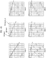
- Target SNR range of reception is from approximately 10 to 20dB, which includes the 15dB SNR reception capability of the existing broadcast system (e.g. ATSC A/53).
- the receiver complexity and power consumption is not as critical as in the battery-operated handheld devices, which will use the handheld profile.
- Key system parameters for the base profile are listed in below table 1.
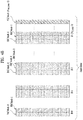
- Table 1 LDPC codeword length 16K, 64K bits Constellation size 4 ⁇ 10 bpcu (bits per channel use) Time de-interleaving memory size ⁇ 2 19 data cells Pilot patterns Pilot pattern for fixed reception FFT size 16K, 32K points
- the handheld profile is designed for use in handheld and vehicular devices that operate with battery power.
- the devices can be moving with pedestrian or vehicle speed.
- the power consumption as well as the receiver complexity is very important for the implementation of the devices of the handheld profile.
- the target SNR range of the handheld profile is approximately 0 to 10dB, but can be configured to reach below 0dB when intended for deeper indoor reception.
- the advanced profile provides highest channel capacity at the cost of more implementation complexity.
- This profile requires using MIMO transmission and reception, and UHDTV service is a target use case for which this profile is specifically designed.
- the increased capacity can also be used to allow an increased number of services in a given bandwidth, e.g., multiple SDTV or HDTV services.
- the target SNR range of the advanced profile is approximately 20 to 30dB.
- MIMO transmission may initially use existing elliptically-polarized transmission equipment, with extension to full-power cross-polarized transmission in the future.
- Key system parameters for the advanced profile are listed in below table 3.
- Table 3 LDPC codeword length 16K, 64K bits Constellation size 8 ⁇ 12 bpcu Time de-interleaving memory size ⁇ 2 19 data cells Pilot patterns Pilot pattern for fixed reception FFT size 16K, 32K points
- the base profile can be used as a profile for both the terrestrial broadcast service and the mobile broadcast service. That is, the base profile can be used to define a concept of a profile which includes the mobile profile. Also, the advanced profile can be divided advanced profile for a base profile with MIMO and advanced profile for a handheld profile with MIMO. Moreover, the three profiles can be changed according to intention of the designer.
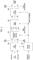
- FIG. 1 illustrates a structure of an apparatus for transmitting broadcast signals for future broadcast services according to an embodiment of the present invention.
- the apparatus for transmitting broadcast signals for future broadcast services can include an input formatting block 1000, a BICM (Bit interleaved coding & modulation) block 1010, a frame structure block 1020, an OFDM (Orthogonal Frequency Division Multiplexing) generation block 1030 and a signaling generation block 1040.
- BICM Bit interleaved coding & modulation
- OFDM Orthogonal Frequency Division Multiplexing
- IP stream/packets and MPEG2-TS are the main input formats, other stream types are handled as General Streams.
- Management Information is input to control the scheduling and allocation of the corresponding bandwidth for each input stream.
- One or multiple TS stream(s), IP stream(s) and/or General Stream(s) inputs are simultaneously allowed.
- the input formatting block 1000 can demultiplex each input stream into one or multiple data pipe(s), to each of which an independent coding and modulation is applied.
- the data pipe (DP) is the basic unit for robustness control, thereby affecting quality-of-service (QoS).
- QoS quality-of-service
- One or multiple service(s) or service component(s) can be carried by a single DP. Details of operations of the input formatting block 1000 will be described later.
- the data pipe is a logical channel in the physical layer that carries service data or related metadata, which may carry one or multiple service(s) or service component(s).
- the data pipe unit a basic unit for allocating data cells to a DP in a frame.
- parity data is added for error correction and the encoded bit streams are mapped to complex-value constellation symbols.
- the symbols are interleaved across a specific interleaving depth that is used for the corresponding DP.
- MIMO encoding is performed in the BICM block 1010 and the additional data path is added at the output for MIMO transmission. Details of operations of the BICM block 1010 will be described later.
- the Frame Building block 1020 can map the data cells of the input DPs into the OFDM symbols within a frame. After mapping, the frequency interleaving is used for frequency-domain diversity, especially to combat frequency-selective fading channels. Details of operations of the Frame Building block 1020 will be described later.
- the OFDM Generation block 1030 can apply conventional OFDM modulation having a cyclic prefix as guard interval. For antenna space diversity, a distributed MISO scheme is applied across the transmitters. In addition, a Peak-to-Average Power Reduction (PAPR) scheme is performed in the time domain. For flexible network planning, this proposal provides a set of various FFT sizes, guard interval lengths and corresponding pilot patterns. Details of operations of the OFDM Generation block 1030 will be described later.
- PAPR Peak-to-Average Power Reduction
- the Signaling Generation block 1040 can create physical layer signaling information used for the operation of each functional block. This signaling information is also transmitted so that the services of interest are properly recovered at the receiver side. Details of operations of the Signaling Generation block 1040 will be described later.
- FIGS. 2 , 3 and 4 illustrate the input formatting block 1000 according to embodiments of the present invention. A description will be given of each figure.
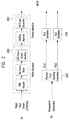
- FIG. 2 illustrates an input formatting block according to one embodiment of the present invention.
- FIG. 2 shows an input formatting module when the input signal is a single input stream.
- the input formatting block illustrated in FIG. 2 corresponds to an embodiment of the input formatting block 1000 described with reference to FIG. 1 .
- the input to the physical layer may be composed of one or multiple data streams. Each data stream is carried by one DP.
- the mode adaptation modules slice the incoming data stream into data fields of the baseband frame (BBF).
- BBF baseband frame
- the system supports three types of input data streams: MPEG2-TS, Internet protocol (IP) and Generic stream (GS).
- MPEG2-TS is characterized by fixed length (188 byte) packets with the first byte being a sync-byte (0x47).
- An IP stream is composed of variable length IP datagram packets, as signaled within IP packet headers.
- the system supports both IPv4 and IPv6 for the IP stream.
- GS may be composed of variable length packets or constant length packets, signaled within encapsulation packet headers.
- the Input Stream Splitter splits the input TS, IP, GS streams into multiple service or service component (audio, video, etc.) streams.
- the mode adaptation module 2010 is comprised of a CRC Encoder, BB (baseband) Frame Slicer, and BB Frame Header Insertion block.
- the CRC Encoder provides three kinds of CRC encoding for error detection at the user packet (UP) level, i.e., CRC-8, CRC-16, and CRC-32.
- the computed CRC bytes are appended after the UP.
- CRC-8 is used for TS stream and CRC-32 for IP stream. If the GS stream doesn't provide the CRC encoding, the proposed CRC encoding should be applied.
- the BB Frame Slicer maps the input into an internal logical-bit format.
- the first received bit is defined to be the MSB.
- the BB Frame Slicer allocates a number of input bits equal to the available data field capacity.
- the UP packet stream is sliced to fit the data field of BBF.
- BB Frame Header Insertion block can insert fixed length BBF header of 2 bytes is inserted in front of the BB Frame.
- the BBF header is composed of STUFFI (1 bit), SYNCD (13 bits), and RFU (2 bits).
- BBF can have an extension field (1 or 3 bytes) at the end of the 2-byte BBF header.
- the stream adaptation 2010 is comprised of stuffing insertion block and BB scrambler.
- the stuffing insertion block can insert stuffing field into a payload of a BB frame. If the input data to the stream adaptation is sufficient to fill a BB-Frame, STUFFI is set to '0' and the BBF has no stuffing field. Otherwise STUFFI is set to '1' and the stuffing field is inserted immediately after the BBF header.
- the stuffing field comprises two bytes of the stuffing field header and a variable size of stuffing data.
- the BB scrambler scrambles complete BBF for energy dispersal.
- the scrambling sequence is synchronous with the BBF.
- the scrambling sequence is generated by the feed-back shift register.
- the PLS generation block 2020 can generate physical layer signaling (PLS) data.
- PLS provides the receiver with a means to access physical layer DPs.
- the PLS data consists of PLS1 data and PLS2 data.
- the PLS1 data is a first set of PLS data carried in the FSS symbols in the frame having a fixed size, coding and modulation, which carries basic information about the system as well as the parameters needed to decode the PLS2 data.
- the PLS1 data provides basic transmission parameters including parameters required to enable the reception and decoding of the PLS2 data. Also, the PLS1 data remains constant for the duration of a frame-group.
- the PLS2 data is a second set of PLS data transmitted in the FSS symbol, which carries more detailed PLS data about the system and the DPs.
- the PLS2 contains parameters that provide sufficient information for the receiver to decode the desired DP.
- the PLS2 signaling further consists of two types of parameters, PLS2 Static data (PLS2-STAT data) and PLS2 dynamic data (PLS2-DYN data).
- PLS2 Static data is PLS2 data that remains static for the duration of a frame-group and the PLS2 dynamic data is PLS2 data that may dynamically change frame-by-frame.
- the PLS scrambler 2030 can scramble the generated PLS data for energy dispersal.
- FIG. 3 illustrates an input formatting block according to another embodiment of the present invention.
- the input formatting block illustrated in FIG. 3 corresponds to an embodiment of the input formatting block 1000 described with reference to FIG. 1 .
- FIG. 3 shows a mode adaptation block of the input formatting block when the input signal corresponds to multiple input streams.
- the mode adaptation block of the input formatting block for processing the multiple input streams can independently process the multiple input streams.
- the mode adaptation block for respectively processing the multiple input streams can include an input stream splitter 3000, an input stream synchronizer 3010, a compensating delay block 3020, a null packet deletion block 3030, a head compression block 3040, a CRC encoder 3050, a BB frame slicer 3060 and a BB header insertion block 3070. Description will be given of each block of the mode adaptation block.
- Operations of the CRC encoder 3050, BB frame slicer 3060 and BB header insertion block 3070 correspond to those of the CRC encoder, BB frame slicer and BB header insertion block described with reference to FIG. 2 and thus description thereof is omitted.
- the input stream splitter 3000 can split the input TS, IP, GS streams into multiple service or service component (audio, video, etc.) streams.
- the input stream synchronizer 3010 may be referred as ISSY.
- the ISSY can provide suitable means to guarantee Constant Bit Rate (CBR) and constant end-to-end transmission delay for any input data format.
- CBR Constant Bit Rate
- the ISSY is always used for the case of multiple DPs carrying TS, and optionally used for multiple DPs carrying GS streams.
- the compensating delay block 3020 can delay the split TS packet stream following the insertion of ISSY information to allow a TS packet recombining mechanism without requiring additional memory in the receiver.
- the null packet deletion block 3030 is used only for the TS input stream case.
- Some TS input streams or split TS streams may have a large number of null-packets present in order to accommodate VBR (variable bit-rate) services in a CBR TS stream.
- null-packets can be identified and not transmitted.
- removed null-packets can be re-inserted in the exact place where they were originally by reference to a deleted null-packet (DNP) counter that is inserted in the transmission, thus guaranteeing constant bit-rate and avoiding the need for time-stamp (PCR) updating.
- DNP deleted null-packet
- the head compression block 3040 can provide packet header compression to increase transmission efficiency for TS or IP input streams. Because the receiver can have a priori information on certain parts of the header, this known information can be deleted in the transmitter.
- the receiver For Transport Stream, the receiver has a-priori information about the sync-byte configuration (0x47) and the packet length (188 Byte). If the input TS stream carries content that has only one PID, i.e., for only one service component (video, audio, etc.) or service sub-component (SVC base layer, SVC enhancement layer, MVC base view or MVC dependent views), TS packet header compression can be applied (optionally) to the Transport Stream. IP packet header compression is used optionally if the input steam is an IP stream.
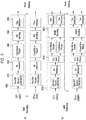
- FIG. 4 illustrates an input formatting block according to another embodiment of the present invention.
- the input formatting block illustrated in FIG. 4 corresponds to an embodiment of the input formatting block 1000 described with reference to FIG. 1 .
- FIG. 4 illustrates a stream adaptation block of the input formatting module when the input signal corresponds to multiple input streams.
- the mode adaptation block for respectively processing the multiple input streams can include a scheduler 4000, an 1-Frame delay block 4010, a stuffing insertion block 4020, an in-band signaling 4030, a BB Frame scrambler 4040, a PLS generation block 4050 and a PLS scrambler 4060. Description will be given of each block of the stream adaptation block.
- Operations of the stuffing insertion block 4020, the BB Frame scrambler 4040, the PLS generation block 4050 and the PLS scrambler 4060 correspond to those of the stuffing insertion block, BB scrambler, PLS generation block and the PLS scrambler described with reference to FIG. 2 and thus description thereof is omitted.
- the scheduler 4000 can determine the overall cell allocation across the entire frame from the amount of FECBLOCKs of each DP. Including the allocation for PLS, EAC and FIC, the scheduler generate the values of PLS2-DYN data, which is transmitted as in-band signaling or PLS cell in FSS of the frame. Details of FECBLOCK, EAC and FIC will be described later.
- the 1-Frame delay block 4010 can delay the input data by one transmission frame such that scheduling information about the next frame can be transmitted through the current frame for in-band signaling information to be inserted into the DPs.
- the in-band signaling 4030 can insert un-delayed part of the PLS2 data into a DP of a frame.
- FIG. 5 illustrates a BICM block according to an embodiment of the present invention.
- the BICM block illustrated in FIG. 5 corresponds to an embodiment of the BICM block 1010 described with reference to FIG. 1 .
- the apparatus for transmitting broadcast signals for future broadcast services can provide a terrestrial broadcast service, mobile broadcast service, UHDTV service, etc.
- the a BICM block according to an embodiment of the present invention can independently process DPs input thereto by independently applying SISO, MISO and MIMO schemes to the data pipes respectively corresponding to data paths. Consequently, the apparatus for transmitting broadcast signals for future broadcast services according to an embodiment of the present invention can control QoS for each service or service component transmitted through each DP.
- the BICM block shared by the base profile and the handheld profile and the BICM block of the advanced profile can include plural processing blocks for processing each DP.
- a processing block 5000 of the BICM block for the base profile and the handheld profile can include a Data FEC encoder 5010, a bit interleaver 5020, a constellation mapper 5030, an SSD (Signal Space Diversity) encoding block 5040 and a time interleaver 5050.
- the Data FEC encoder 5010 can perform the FEC encoding on the input BBF to generate FECBLOCK procedure using outer coding (BCH), and inner coding (LDPC).
- BCH outer coding
- LDPC inner coding
- the outer coding (BCH) is optional coding method. Details of operations of the Data FEC encoder 5010 will be described later.
- the bit interleaver 5020 can interleave outputs of the Data FEC encoder 5010 to achieve optimized performance with combination of the LDPC codes and modulation scheme while providing an efficiently implementable structure. Details of operations of the bit interleaver 5020 will be described later.
- the constellation mapper 5030 can modulate each cell word from the bit interleaver 5020 in the base and the handheld profiles, or cell word from the Cell-word demultiplexer 5010-1 in the advanced profile using either QPSK, QAM-16, non-uniform QAM (NUQ-64, NUQ-256, NUQ-1024) or non-uniform constellation (NUC-16, NUC-64, NUC-256, NUC-1024) to give a power-normalized constellation point, el.
- This constellation mapping is applied only for DPs. Observe that QAM-16 and NUQs are square shaped, while NUCs have arbitrary shape. When each constellation is rotated by any multiple of 90 degrees, the rotated constellation exactly overlaps with its original one.
- the SSD encoding block 5040 can precode cells in two (2D), three (3D), and four (4D) dimensions to increase the reception robustness under difficult fading conditions.
- the time interleaver 5050 can operates at the DP level.
- the parameters of time interleaving (TI) may be set differently for each DP. Details of operations of the time interleaver 5050 will be described later.
- a processing block 5000-1 of the BICM block for the advanced profile can include the Data FEC encoder, bit interleaver, constellation mapper, and time interleaver. However, the processing block 5000-1 is distinguished from the processing block 5000 further includes a cell-word demultiplexer 5010-1 and a MIMO encoding block 5020-1.
- the operations of the Data FEC encoder, bit interleaver, constellation mapper, and time interleaver in the processing block 5000-1 correspond to those of the Data FEC encoder 5010, bit interleaver 5020, constellation mapper 5030, and time interleaver 5050 described and thus description thereof is omitted.
- the cell-word demultiplexer 5010-1 is used for the DP of the advanced profile to divide the single cell-word stream into dual cell-word streams for MIMO processing. Details of operations of the cell-word demultiplexer 5010-1 will be described later.
- the MIMO encoding block 5020-1 can processing the output of the cell-word demultiplexer 5010-1 using MIMO encoding scheme.
- the MIMO encoding scheme was optimized for broadcasting signal transmission.
- the MIMO technology is a promising way to get a capacity increase but it depends on channel characteristics. Especially for broadcasting, the strong LOS component of the channel or a difference in the received signal power between two antennas caused by different signal propagation characteristics makes it difficult to get capacity gain from MIMO.
- the proposed MIMO encoding scheme overcomes this problem using a rotation-based pre-coding and phase randomization of one of the MIMO output signals.
- MIMO encoding is intended for a 2x2 MIMO system requiring at least two antennas at both the transmitter and the receiver.
- Two MIMO encoding modes are defined in this proposal; full-rate spatial multiplexing (FR-SM) and full-rate full-diversity spatial multiplexing (FRFD-SM).
- FR-SM full-rate spatial multiplexing
- FRFD-SM full-rate full-diversity spatial multiplexing
- the FR-SM encoding provides capacity increase with relatively small complexity increase at the receiver side while the FRFD-SM encoding provides capacity increase and additional diversity gain with a great complexity increase at the receiver side.
- the proposed MIMO encoding scheme has no restriction on the antenna polarity configuration.
- MIMO processing is required for the advanced profile frame, which means all DPs in the advanced profile frame are processed by the MIMO encoder. MIMO processing is applied at DP level. Pairs of the Constellation Mapper outputs NUQ (e1,i and e2,i) are fed to the input of the MIMO Encoder. Paired MIMO Encoder output (g1,i and g2,i) is transmitted by the same carrier k and OFDM symbol 1 of their respective TX antennas.
- FIG. 6 illustrates a BICM block according to another embodiment of the present invention.
- the BICM block illustrated in FIG. 6 corresponds to an embodiment of the BICM block 1010 described with reference to FIG. 1 .
- FIG. 6 illustrates a BICM block for protection of physical layer signaling (PLS), emergency alert channel (EAC) and fast information channel (FIC).
- PLS physical layer signaling
- EAC emergency alert channel
- FIC fast information channel
- the BICM block for protection of PLS, EAC and FIC can include a PLS FEC encoder 6000, a bit interleaver 6010 and a constellation mapper 6020.
- the PLS FEC encoder 6000 can include a scrambler, BCH encoding/zero insertion block, LDPC encoding block and LDPC parity punturing block. Description will be given of each block of the BICM block.
- the PLS FEC encoder 6000 can encode the scrambled PLS 1/2 data, EAC and FIC section.
- the scrambler can scramble PLS1 data and PLS2 data before BCH encoding and shortened and punctured LDPC encoding.
- the BCH encoding/zero insertion block can perform outer encoding on the scrambled PLS 1/2 data using the shortened BCH code for PLS protection and insert zero bits after the BCH encoding.
- the output bits of the zero insertion may be permutted before LDPC encoding.
- the LDPC encoding block can encode the output of the BCH encoding/zero insertion block using LDPC code.
- Cldpc parity bits
- Pldpc are encoded systematically from each zero-inserted PLS information block, Ildpc and appended after it.
- C ldpc I ldpc
- P ldpc i 0 , i 1 , ... , i K ldpc ⁇ 1 , p 0 , p 1 , ... , p N ldpc ⁇ K ldpc ⁇ 1
- the LDPC code parameters for PLS1 and PLS2 are as following table 4.
- the LDPC parity punturing block can perform puncturing on the PLS1 data and PLS 2 data.
- the bit interleaver 6010 can interleave the each shortened and punctured PLS1 data and PLS2 data.
- the constellation mapper 6020 can map the bit ineterlaeved PLS1 data and PLS2 data onto constellations.
- FIG. 7 illustrates a frame building block according to one embodiment of the present invention.
- the frame building block illustrated in FIG. 7 corresponds to an embodiment of the frame building block 1020 described with reference to FIG. 1 .
- the frame building block can include a delay compensation block 7000, a cell mapper 7010 and a frequency interleaver 7020. Description will be given of each block of the frame building block.
- the delay compensation block 7000 can adjust the timing between the data pipes and the corresponding PLS data to ensure that they are co-timed at the transmitter end.
- the PLS data is delayed by the same amount as data pipes are by addressing the delays of data pipes caused by the Input Formatting block and BICM block.
- the delay of the BICM block is mainly due to the time interleaver 5050.
- In-band signaling data carries information of the next TI group so that they are carried one frame ahead of the DPs to be signaled.
- the Delay Compensating block delays in-band signaling data accordingly.
- the cell mapper 7010 can map PLS, EAC, FIC, DPs, auxiliary streams and dummy cells into the active carriers of the OFDM symbols in the frame.
- the basic function of the cell mapper 7010 is to map data cells produced by the TIs for each of the DPs, PLS cells, and EAC/FIC cells, if any, into arrays of active OFDM cells corresponding to each of the OFDM symbols within a frame.
- Service signaling data (such as PSI(program specific information)/SI) can be separately gathered and sent by a data pipe.
- the Cell Mapper operates according to the dynamic information produced by the scheduler and the configuration of the frame structure. Details of the frame will be described later.
- the frequency interleaver 7020 can randomly interleave data cells received from the cell mapper 7010 to provide frequency diversity. Also, the frequency interleaver 7020 can operate on very OFDM symbol pair comprised of two sequential OFDM symbols using a different interleaving-seed order to get maximum interleaving gain in a single frame.
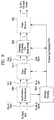
- FIG. 8 illustrates an OFDM generation block according to an embodiment of the present invention.
- the OFDM generation block illustrated in FIG. 8 corresponds to an embodiment of the OFDM generation block 1030 described with reference to FIG. 1 .
- the OFDM generation block modulates the OFDM carriers by the cells produced by the Frame Building block, inserts the pilots, and produces the time domain signal for transmission. Also, this block subsequently inserts guard intervals, and applies PAPR (Peak-to-Average Power Radio) reduction processing to produce the final RF signal.
- PAPR Peak-to-Average Power Radio
- the frame building block can include a pilot and reserved tone insertion block 8000, a 2D-eSFN encoding block 8010, an IFFT (Inverse Fast Fourier Transform) block 8020, a PAPR reduction block 8030, a guard interval insertion block 8040, a preamble insertion block 8050, other system insertion block 8060 and a DAC block 8070. Description will be given of each block of the frame building block.
- IFFT Inverse Fast Fourier Transform
- the pilot and reserved tone insertion block 8000 can insert pilots and the reserved tone.
- pilots which have transmitted values known a priori in the receiver.
- the information of pilot cells is made up of scattered pilots, continual pilots, edge pilots, FSS (frame signaling symbol) pilots and FES (frame edge symbol) pilots.
- Each pilot is transmitted at a particular boosted power level according to pilot type and pilot pattern.
- the value of the pilot information is derived from a reference sequence, which is a series of values, one for each transmitted carrier on any given symbol.
- the pilots can be used for frame synchronization, frequency synchronization, time synchronization, channel estimation, and transmission mode identification, and also can be used to follow the phase noise.
- Reference information, taken from the reference sequence, is transmitted in scattered pilot cells in every symbol except the preamble, FSS and FES of the frame.
- Continual pilots are inserted in every symbol of the frame. The number and location of continual pilots depends on both the FFT size and the scattered pilot pattern.
- the edge carriers are edge pilots in every symbol except for the preamble symbol. They are inserted in order to allow frequency interpolation up to the edge of the spectrum.
- FSS pilots are inserted in FSS(s) and FES pilots are inserted in FES. They are inserted in order to allow time interpolation up to the edge of the frame.
- the system according to an embodiment of the present invention supports the SFN network, where distributed MISO scheme is optionally used to support very robust transmission mode.
- the 2D-eSFN is a distributed MISO scheme that uses multiple TX antennas, each of which is located in the different transmitter site in the SFN network.
- the 2D-eSFN encoding block 8010 can process a 2D-eSFN processing to distorts the phase of the signals transmitted from multiple transmitters, in order to create both time and frequency diversity in the SFN configuration. Hence, burst errors due to low flat fading or deep-fading for a long time can be mitigated.
- the IFFT block 8020 can modulate the output from the 2D-eSFN encoding block 8010 using OFDM modulation scheme. Any cell in the data symbols which has not been designated as a pilot (or as a reserved tone) carries one of the data cells from the frequency interleaver. The cells are mapped to OFDM carriers.
- the PAPR reduction block 8030 can perform a PAPR reduction on input signal using various PAPR reduction algorithm in the time domain.
- the guard interval insertion block 8040 can insert guard intervals and the preamble insertion block 8050 can insert preamble in front of the signal. Details of a structure of the preamble will be described later.
- the other system insertion block 8060 can multiplex signals of a plurality of broadcast transmission/reception systems in the time domain such that data of two or more different broadcast transmission/reception systems providing broadcast services can be simultaneously transmitted in the same RF signal bandwidth.
- the two or more different broadcast transmission/reception systems refer to systems providing different broadcast services.
- the different broadcast services may refer to a terrestrial broadcast service, mobile broadcast service, etc. Data related to respective broadcast services can be transmitted through different frames.
- the DAC block 8070 can convert an input digital signal into an analog signal and output the analog signal.
- the signal output from the DAC block 7800 can be transmitted through multiple output antennas according to the physical layer profiles.
- a Tx antenna according to an embodiment of the present invention can have vertical or horizontal polarity.
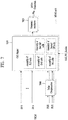
- FIG. 9 illustrates a structure of an apparatus for receiving broadcast signals for future broadcast services according to an embodiment of the present invention.
- the apparatus for receiving broadcast signals for future broadcast services can correspond to the apparatus for transmitting broadcast signals for future broadcast services, described with reference to FIG. 1 .
- the apparatus for receiving broadcast signals for future broadcast services can include a synchronization & demodulation module 9000, a frame parsing module 9010, a demapping & decoding module 9020, an output processor 9030 and a signaling decoding module 9040. A description will be given of operation of each module of the apparatus for receiving broadcast signals.
- the synchronization & demodulation module 9000 can receive input signals through m Rx antennas, perform signal detection and synchronization with respect to a system corresponding to the apparatus for receiving broadcast signals and carry out demodulation corresponding to a reverse procedure of the procedure performed by the apparatus for transmitting broadcast signals.
- the frame parsing module 9100 can parse input signal frames and extract data through which a service selected by a user is transmitted. If the apparatus for transmitting broadcast signals performs interleaving, the frame parsing module 9100 can carry out deinterleaving corresponding to a reverse procedure of interleaving. In this case, the positions of a signal and data that need to be extracted can be obtained by decoding data output from the signaling decoding module 9400 to restore scheduling information generated by the apparatus for transmitting broadcast signals.
- the demapping & decoding module 9200 can convert the input signals into bit domain data and then deinterleave the same as necessary.
- the demapping & decoding module 9200 can perform demapping for mapping applied for transmission efficiency and correct an error generated on a transmission channel through decoding. In this case, the demapping & decoding module 9200 can obtain transmission parameters necessary for demapping and decoding by decoding the data output from the signaling decoding module 9400.
- the output processor 9300 can perform reverse procedures of various compression/signal processing procedures which are applied by the apparatus for transmitting broadcast signals to improve transmission efficiency.
- the output processor 9300 can acquire necessary control information from data output from the signaling decoding module 9400.
- the output of the output processor 8300 corresponds to a signal input to the apparatus for transmitting broadcast signals and may be MPEG-TSs, IP streams (v4 or v6) and generic streams.
- the signaling decoding module 9400 can obtain PLS information from the signal demodulated by the synchronization & demodulation module 9000. As described above, the frame parsing module 9100, demapping & decoding module 9200 and output processor 9300 can execute functions thereof using the data output from the signaling decoding module 9400.
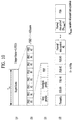
- FIG. 10 illustrates a frame structure according to an embodiment of the present invention.
- FIG. 10 shows an example configuration of the frame types and FRUs in a super-frame.
- (a) shows a super frame according to an embodiment of the present invention
- (b) shows FRU (Frame Repetition Unit) according to an embodiment of the present invention
- (c) shows frames of variable PHY profiles in the FRU
- (d) shows a structure of a frame.
- a super-frame may be composed of eight FRUs.
- the FRU is a basic multiplexing unit for TDM of the frames, and is repeated eight times in a super-frame.
- Each frame in the FRU belongs to one of the PHY profiles, (base, handheld, advanced) or FEF.
- the maximum allowed number of the frames in the FRU is four and a given PHY profile can appear any number of times from zero times to four times in the FRU (e.g., base, base, handheld, advanced).
- PHY profile definitions can be extended using reserved values of the PHY_PROFILE in the preamble, if required.
- the FEF part is inserted at the end of the FRU, if included.
- the minimum number of FEFs is 8 in a super-frame. It is not recommended that FEF parts be adjacent to each other.
- One frame is further divided into a number of OFDM symbols and a preamble. As shown in (d), the frame comprises a preamble, one or more frame signaling symbols (FSS), normal data symbols and a frame edge symbol (FES).
- FSS frame signaling symbols
- FES normal data symbols
- FES frame edge symbol
- the preamble is a special symbol that enables fast Futurecast UTB system signal detection and provides a set of basic transmission parameters for efficient transmission and reception of the signal. The detailed description of the preamble will be will be described later.
- the main purpose of the FSS(s) is to carry the PLS data.
- the FSS For fast synchronization and channel estimation, and hence fast decoding of PLS data, the FSS has more dense pilot pattern than the normal data symbol.
- the FES has exactly the same pilots as the FSS, which enables frequency-only interpolation within the FES and temporal interpolation, without extrapolation, for symbols immediately preceding the FES.
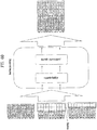
- FIG. 11 illustrates a signaling hierarchy structure of the frame according to an embodiment of the present invention.
- FIG. 11 illustrates the signaling hierarchy structure, which is split into three main parts: the preamble signaling data 11000, the PLS1 data 11010 and the PLS2 data 11020.
- the purpose of the preamble which is carried by the preamble symbol in every frame, is to indicate the transmission type and basic transmission parameters of that frame.
- the PLS1 enables the receiver to access and decode the PLS2 data, which contains the parameters to access the DP of interest.
- the PLS2 is carried in every frame and split into two main parts: PLS2-STAT data and PLS2-DYN data. The static and dynamic portion of PLS2 data is followed by padding, if necessary.
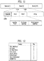
- FIG. 12 illustrates preamble signaling data according to an embodiment of the present invention.
- Preamble signaling data carries 21 bits of information that are needed to enable the receiver to access PLS data and trace DPs within the frame structure. Details of the preamble signaling data are as follows: PHY_PROFILE: This 3-bit field indicates the PHY profile type of the current frame. The mapping of different PHY profile types is given in below table 5. [Table 5] Value PHY profile 000 Base profile 001 Handheld profile 010 Advanced profiled 011 ⁇ 110 Reserved 111 FEF FFT_SIZE: This 2 bit field indicates the FFT size of the current frame within a frame-group, as described in below table 6.
- GI_FRACTION This 3 bit field indicates the guard interval fraction value in the current super-frame, as described in below table 7.
- EAC_FLAG This 1 bit field indicates whether the EAC is provided in the current frame. If this field is set to '1', emergency alert service (EAS) is provided in the current frame. If this field set to '0', EAS is not carried in the current frame. This field can be switched dynamically within a super-frame.
- EAS emergency alert service
- PILOT_MODE This 1-bit field indicates whether the pilot mode is mobile mode or fixed mode for the current frame in the current frame-group. If this field is set to '0', mobile pilot mode is used. If the field is set to '1', the fixed pilot mode is used.
- PAPR_FLAG This 1-bit field indicates whether PAPR reduction is used for the current frame in the current frame-group. If this field is set to value '1', tone reservation is used for PAPR reduction. If this field is set to '0', PAPR reduction is not used.
- FRU CONFIGURE This 3-bit field indicates the PHY profile type configurations of the frame repetition units (FRU) that are present in the current super-frame.
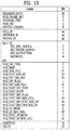
- FIG. 13 illustrates PLS1 data according to an embodiment of the present invention.
- PLS1 data provides basic transmission parameters including parameters required to enable the reception and decoding of the PLS2. As above mentioned, the PLS1 data remain unchanged for the entire duration of one frame-group.
- the detailed definition of the signaling fields of the PLS1 data are as follows: PREAMBLE_DATA: This 20-bit field is a copy of the preamble signaling data excluding the EAC_FLAG. NUM FRAME_FRU: This 2-bit field indicates the number of the frames per FRU.
- PAYLOAD_TYPE This 3-bit field indicates the format of the payload data carried in the frame-group. PAYLOAD_TYPE is signaled as shown in table 9.
- CELL_ID This is a 16-bit field which uniquely identifies a geographic cell in an ATSC network.
- An ATSC cell coverage area may consist of one or more frequencies, depending on the number of frequencies used per Futurecast UTB system. If the value of the CELL_ID is not known or unspecified, this field is set to '0'.
- NETWORK_ID This is a 16-bit field which uniquely identifies the current ATSC network.
- SYSTEM_ID This 16-bit field uniquely identifies the Futurecast UTB system within the ATSC network.
- the Futurecast UTB system is the terrestrial broadcast system whose input is one or more input streams (TS, IP, GS) and whose output is an RF signal.
- the Futurecast UTB system carries one or more PHY profiles and FEF, if any.
- the same Futurecast UTB system may carry different input streams and use different RF frequencies in different geographical areas, allowing local service insertion.
- the frame structure and scheduling is controlled in one place and is identical for all transmissions within a Futurecast UTB system.
- One or more Futurecast UTB systems may have the same SYSTEM_ID meaning that they all have the same physical layer structure and configuration.
- the following loop consists of FRU_PHY_PROFILE, FRU_FRAME_LENGTH, FRU_GI_FRACTION, and RESERVED which are used to indicate the FRU configuration and the length of each frame type.
- the loop size is fixed so that four PHY profiles (including a FEF) are signaled within the FRU. If NUM_FRAME_FRU is less than 4, the unused fields are filled with zeros.
- PLS2_FEC_TYPE This 2-bit field indicates the FEC type used by the PLS2 protection. The FEC type is signaled according to table 10. The details of the LDPC codes will be described later. [Table 10] Content PLS2 FEC type 00 4K-1/4 and 7K-3/10 LDPC codes 01 ⁇ 11 Reserved PLS2_MOD: This 3-bit field indicates the modulation type used by the PLS2. The modulation type is signaled according to table 11.
- PLS2_STAT_SIZE_BIT This 14-bit field indicates the size, in bits, of the PLS2-STAT for the current frame-group. This value is constant during the entire duration of the current frame-group.
- PLS2_DYN_SIZE_BIT This 14-bit field indicates the size, in bits, of the PLS2-DYN for the current frame-group. This value is constant during the entire duration of the current frame-group.
- PLS2_REP_FLAG This 1-bit flag indicates whether the PLS2 repetition mode is used in the current frame-group. When this field is set to value '1', the PLS2 repetition mode is activated. When this field is set to value '0', the PLS2 repetition mode is deactivated.
- PLS2_REP_SIZE_CELL This 15-bit field indicates Ctotal_partial_block, the size (specified as the number of QAM cells) of the collection of partial coded blocks for PLS2 carried in every frame of the current frame-group, when PLS2 repetition is used. If repetition is not used, the value of this field is equal to 0. This value is constant during the entire duration of the current frame-group.
- PLS2_NEXT_FEC_TYPE This 2-bit field indicates the FEC type used for PLS2 that is carried in every frame of the next frame-group. The FEC type is signaled according to the table 10.
- PLS2_NEXT_MOD This 3-bit field indicates the modulation type used for PLS2 that is carried in every frame of the next frame-group. The modulation type is signaled according to the table 11.
- PLS2_NEXT_REP_FLAG This 1-bit flag indicates whether the PLS2 repetition mode is used in the next frame-group. When this field is set to value '1', the PLS2 repetition mode is activated. When this field is set to value '0', the PLS2 repetition mode is deactivated.
- PLS2 _NEXT_REP_SIZE_CELL This 15-bit field indicates Ctotal_full_block, The size (specified as the number of QAM cells) of the collection of full coded blocks for PLS2 that is carried in every frame of the next frame-group, when PLS2 repetition is used. If repetition is not used in the next frame-group, the value of this field is equal to 0. This value is constant during the entire duration of the current frame-group.
- PLS2_NEXT_REP_STAT_SIZE_BIT This 14-bit field indicates the size, in bits, of the PLS2-STAT for the next frame-group. This value is constant in the current frame-group.
- PLS2 _NEXT_REP_DYN_SIZE_BIT This 14-bit field indicates the size, in bits, of the PLS2-DYN for the next frame-group. This value is constant in the current frame-group.
- PLS2_AP_MODE This 2-bit field indicates whether additional parity is provided for PLS2 in the current frame-group. This value is constant during the entire duration of the current frame-group. The below table 12 gives the values of this field. When this field is set to '00', additional parity is not used for the PLS2 in the current frame-group.
- PLS2_NEXT_AP_MODE This 2-bit field indicates whether additional parity is provided for PLS2 signaling in every frame of next frame-group. This value is constant during the entire duration of the current frame-group.
- the table 12 defines the values of this field PLS2 _NEXT_AP_SIZE_CELL: This 15-bit field indicates the size (specified as the number of QAM cells) of the additional parity bits of the PLS2 in every frame of the next frame-group. This value is constant during the entire duration of the current frame-group. RESERVED: This 32-bit field is reserved for future use. CRC_32: A 32-bit error detection code, which is applied to the entire PLS1 signaling.
- FIG. 14 illustrates PLS2 data according to an embodiment of the present invention.
- FIG. 14 illustrates PLS2-STAT data of the PLS2 data.
- the PLS2-STAT data are the same within a frame-group, while the PLS2-DYN data provide information that is specific for the current frame.
- FIC_FLAG This 1-bit field indicates whether the FIC is used in the current frame-group. If this field is set to '1', the FIC is provided in the current frame. If this field set to '0', the FIC is not carried in the current frame. This value is constant during the entire duration of the current frame-group.
- AUX_FLAG This 1-bit field indicates whether the auxiliary stream(s) is used in the current frame-group. If this field is set to '1', the auxiliary stream is provided in the current frame. If this field set to '0', the auxiliary stream is not carried in the current frame. This value is constant during the entire duration of current frame-group.
- NUM_DP This 6-bit field indicates the number of DPs carried within the current frame. The value of this field ranges from 1 to 64, and the number of DPs is NUM_DP+1.
- DP_ID This 6-bit field identifies uniquely a DP within a PHY profile.
- DP_TYPE This 3-bit field indicates the type of the DP. This is signaled according to the below table 13. [Table 13] Value DP Type 000 DP Type 1 001 DP Type 2 010 ⁇ 111 reserved DP_GROUP_ID: This 8-bit field identifies the DP group with which the current DP is associated.
- BASE_DP_ID This 6-bit field indicates the DP carrying service signaling data (such as PSI/SI) used in the Management layer.
- the DP indicated by BASE_DP_ID may be either a normal DP carrying the service signaling data along with the service data or a dedicated DP carrying only the service signaling data
- DP_FEC_TYPE This 2-bit field indicates the FEC type used by the associated DP. The FEC type is signaled according to the below table 14.
- DP_MIMO This 3-bit field indicates which type of MIMO encoding process is applied to the associated DP.
- the type of MIMO encoding process is signaled according to the table 17. [Table 17] Value MIMO encoding 000 FR-SM 001 FRFD-SM 010 ⁇ 111 reserved DP_TI_TYPE: This 1-bit field indicates the type of time-interleaving. A value of '0' indicates that one TI group corresponds to one frame and contains one or more TI-blocks. A value of '1' indicates that one TI group is carried in more than one frame and contains only one TI-block.
- the allowed PI values with 2-bit field are defined in the below table 18.
- the allowed PI values with 2-bit field are defined in the below table 18.
- DP_FRAME_INTERVAL This 2-bit field indicates the frame interval (IJUMP) within the frame-group for the associated DP and the allowed values are 1, 2, 4, 8 (the corresponding 2-bit field is '00', '01', '10', or '11', respectively).
- DP_TI_BYPASS This 1-bit field determines the availability of time interleaver 5050. If time interleaving is not used for a DP, it is set to '1'. Whereas if time interleaving is used it is set to '0'.
- DP_FIRST_FRAME_IDX This 5-bit field indicates the index of the first frame of the super-frame in which the current DP occurs.
- DP_FIRST_FRAME_IDX ranges from 0 to 31 DP_NUM_BLOCK_MAX: This 10-bit field indicates the maximum value of DP_NUM_BLOCKS for this DP. The value of this field has the same range as DP_NUM_BLOCKS.
- DP_PAYLOAD_TYPE This 2-bit field indicates the type of the payload data carried by the given DP. DP_PAYLOAD_TYPE is signaled according to the below table 19. [Table 19] Value Payload Type 00 TS. 01 IP 10 GS 11 reserved DP_INBAND_MODE: This 2-bit field indicates whether the current DP carries in-band signaling information.
- the in-band signaling type is signaled according to the below table 20.
- the HC_MODE_TS is signaled according to the below table 25.
- HC_MODE_IP is signaled according to the below table 26.
- Table 26 Value Header compression mode 00 No compression 01 HC_MODE_IP 1 10 ⁇ 11 reserved PID : This 13-bit field indicates the PID number for TS header compression when DP_PAYLOAD_TYPE is set to TS ('00') and HC_MODE _TS is set to '01' or '10'.
- RESERVED This 8-bit field is reserved for future use.
- FIG. 15 illustrates PLS2 data according to another embodiment of the present invention.
- FIG. 15 illustrates PLS2-DYN data of the PLS2 data.
- the values of the PLS2-DYN data may change during the duration of one frame-group, while the size of fields remains constant.
- DP ID This 6-bit field indicates uniquely the DP within a PHY profile.
- DP_START This 15-bit (or 13-bit) field indicates the start position of the first of the DPs using the DPU addressing scheme.
- the DP_START field has differing length according to the PHY profile and FFT size as shown in the below table 27. [Table 27] PHY profile DP_START field size 64K 16K Base 13 bit 15 bit Handheld - 13 bit Advanced 13 bit 15 bit DP_NUM_BLOCK: This 10-bit field indicates the number of FEC blocks in the current TI group for the current DP.
- the value of DP_NUM_BLOCK ranges from 0 to 1023 RESERVED: This 8-bit field is reserved for future use.
- the following fields indicate the FIC parameters associated with the EAC.
- EAC_FLAG field is equal to '1', the following 12 bits are allocated for EAC_LENGTH_BYTE field. If the EAC_FLAG field is equal to '0', the following 12 bits are allocated for EAC_COUNTER.
- FIG. 16 illustrates a logical structure of a frame according to an embodiment of the present invention.
- the PLS, EAC, FIC, DPs, auxiliary streams and dummy cells are mapped into the active carriers of the OFDM symbols in the frame.
- the PLS1 and PLS2 are first mapped into one or more FSS(s). After that, EAC cells, if any, are mapped immediately following the PLS field, followed next by FIC cells, if any.
- the DPs are mapped next after the PLS or EAC, FIC, if any. Type 1 DPs follows first, and Type 2 DPs next. The details of a type of the DP will be described later. In some case, DPs may carry some special data for EAS or service signaling data.
- auxiliary stream or streams follow the DPs, which in turn are followed by dummy cells. Mapping them all together in the above mentioned order, i.e. PLS, EAC, FIC, DPs, auxiliary streams and dummy data cells exactly fill the cell capacity in the frame.
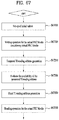
- FIG. 17 illustrates PLS mapping according to an embodiment of the present invention.
- PLS cells are mapped to the active carriers of FSS(s). Depending on the number of cells occupied by PLS, one or more symbols are designated as FSS(s), and the number of FSS(s) NFSS is signaled by NUM_FSS in PLS1.
- the FSS is a special symbol for carrying PLS cells. Since robustness and latency are critical issues in the PLS, the FSS(s) has higher density of pilots allowing fast synchronization and frequency-only interpolation within the FSS.
- PLS cells are mapped to active carriers of the NFSS FSS(s) in a top-down manner as shown in an example in FIG. 17 .
- the PLS1 cells are mapped first from the first cell of the first FSS in an increasing order of the cell index.
- the PLS2 cells follow immediately after the last cell of the PLS1 and mapping continues downward until the last cell index of the first FSS. If the total number of required PLS cells exceeds the number of active carriers of one FSS, mapping proceeds to the next FSS and continues in exactly the same manner as the first FSS.
- DPs are carried next. If EAC, FIC or both are present in the current frame, they are placed between PLS and "normal" DPs.
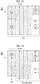
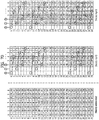
- FIG. 18 illustrates EAC mapping according to an embodiment of the present invention.
- EAC is a dedicated channel for carrying EAS messages and links to the DPs for EAS. EAS support is provided but EAC itself may or may not be present in every frame. EAC, if any, is mapped immediately after the PLS2 cells. EAC is not preceded by any of the FIC, DPs, auxiliary streams or dummy cells other than the PLS cells. The procedure of mapping the EAC cells is exactly the same as that of the PLS.
- EAC cells are mapped from the next cell of the PLS2 in increasing order of the cell index as shown in the example in FIG. 18 .
- EAC cells may occupy a few symbols, as shown in FIG. 18 .
- EAC cells follow immediately after the last cell of the PLS2, and mapping continues downward until the last cell index of the last FSS. If the total number of required EAC cells exceeds the number of remaining active carriers of the last FSS mapping proceeds to the next symbol and continues in exactly the same manner as FSS(s).
- the next symbol for mapping in this case is the normal data symbol, which has more active carriers than a FSS.
- FIC is carried next, if any exists. If FIC is not transmitted (as signaled in the PLS2 field), DPs follow immediately after the last cell of the EAC.
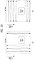
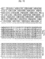
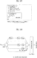
- FIG. 19 illustrates FIC mapping according to an embodiment of the present invention.
- FIC is a dedicated channel for carrying cross-layer information to enable fast service acquisition and channel scanning. This information primarily includes channel binding information between DPs and the services of each broadcaster. For fast scan, a receiver can decode FIC and obtain information such as broadcaster ID, number of services, and BASE_DP_ID. For fast service acquisition, in addition to FIC, base DP can be decoded using BASE_DP_ID. Other than the content it carries, a base DP is encoded and mapped to a frame in exactly the same way as a normal DP. Therefore, no additional description is required for a base DP.
- the FIC data is generated and consumed in the Management Layer. The content of FIC data is as described in the Management Layer specification.
- the FIC data is optional and the use of FIC is signaled by the FIC_FLAG parameter in the static part of the PLS2. If FIC is used, FIC_FLAG is set to '1' and the signaling field for FIC is defined in the static part of PLS2. Signaled in this field are FIC_VERSION, and FIC_LENGTH_BYTE. FIC uses the same modulation, coding and time interleaving parameters as PLS2. FIC shares the same signaling parameters such as PLS2_MOD and PLS2_FEC. FIC data, if any, is mapped immediately after PLS2 or EAC if any. FIC is not preceded by any normal DPs, auxiliary streams or dummy cells. The method of mapping FIC cells is exactly the same as that of EAC which is again the same as PLS.
- FIC cells are mapped from the next cell of the PLS2 in an increasing order of the cell index as shown in an example in (a).
- FIC cells may be mapped over a few symbols, as shown in (b).
- mapping proceeds to the next symbol and continues in exactly the same manner as FSS(s).
- the next symbol for mapping in this case is the normal data symbol which has more active carriers than a FSS.
- EAC precedes FIC, and FIC cells are mapped from the next cell of the EAC in an increasing order of the cell index as shown in (b).
- one or more DPs are mapped, followed by auxiliary streams, if any, and dummy cells.
- FIG. 20 illustrates a type of DP according to an embodiment of the present invention. shows type 1 DP and (b) shows type 2 DP.
- a DP is categorized into one of two types according to mapping method:
- FIG. 20 illustrates the mapping orders of Type 1 DPs and Type 2 DPs.
- Type 2 DPs are first mapped in the increasing order of symbol index, and then after reaching the last OFDM symbol of the frame, the cell index increases by one and the symbol index rolls back to the first available symbol and then increases from that symbol index. After mapping a number of DPs together in one frame, each of the Type 2 DPs are grouped in frequency together, similar to FDM multiplexing of DPs.
- Type 1 DPs and Type 2 DPs can coexist in a frame if needed with one restriction; Type 1 DPs always precede Type 2 DPs.
- the total number of OFDM cells carrying Type 1 and Type 2 DPs cannot exceed the total number of OFDM cells available for transmission of DPs: D DP 1 + D DP 2 ⁇ D DP
- DDP1 is the number of OFDM cells occupied by Type 1 DPs
- DDP2 is the number of cells occupied by Type 2 DPs. Since PLS, EAC, FIC are all mapped in the same way as Type 1 DP, they all follow "Type 1 mapping rule". Hence, overall, Type 1 mapping always precedes Type 2 mapping.
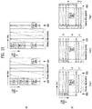
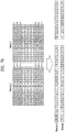
- FIG. 21 illustrates DP mapping according to an embodiment of the present invention. shows an addressing of OFDM cells for mapping type 1 DPs and (b) shows an an addressing of OFDM cells for mapping for type 2 DPs.
- Addressing of OFDM cells for mapping Type 1 DPs (0, ..., DDP1-1) is defined for the active data cells of Type 1 DPs.
- the addressing scheme defines the order in which the cells from the TIs for each of the Type 1 DPs are allocated to the active data cells. It is also used to signal the locations of the DPs in the dynamic part of the PLS2.
- address 0 refers to the cell immediately following the last cell carrying PLS in the last FSS. If EAC is transmitted and FIC is not in the corresponding frame, address 0 refers to the cell immediately following the last cell carrying EAC. If FIC is transmitted in the corresponding frame, address 0 refers to the cell immediately following the last cell carrying FIC. Address 0 for Type 1 DPs can be calculated considering two different cases as shown in (a). In the example in (a), PLS, EAC and FIC are assumed to be all transmitted. Extension to the cases where either or both of EAC and FIC are omitted is straightforward. If there are remaining cells in the FSS after mapping all the cells up to FIC as shown on the left side of (a).
- Addressing of OFDM cells for mapping Type 2 DPs (0, ..., DDP2-1) is defined for the active data cells of Type 2 DPs.
- the addressing scheme defines the order in which the cells from the TIs for each of the Type 2 DPs are allocated to the active data cells. It is also used to signal the locations of the DPs in the dynamic part of the PLS2.
- Type 1 DP(s) precede Type 2 DP(s) is straightforward since PLS, EAC and FIC follow the same "Type 1 mapping rule" as the Type 1 DP(s).
- a data pipe unit is a basic unit for allocating data cells to a DP in a frame.
- a DPU is defined as a signaling unit for locating DPs in a frame.
- a Cell Mapper 7010 may map the cells produced by the TIs for each of the DPs.
- a Time interleaver 5050 outputs a series of TI-blocks and each TI-block comprises a variable number of XFECBLOCKs which is in turn composed of a set of cells. The number of cells in an XFECBLOCK, Ncells, is dependent on the FECBLOCK size, Nldpc, and the number of transmitted bits per constellation symbol.
- a DPU is defined as the greatest common divisor of all possible values of the number of cells in a XFECBLOCK, Ncells, supported in a given PHY profile. The length of a DPU in cells is defined as LDPU. Since each PHY profile supports different combinations of FECBLOCK size and a different number of bits per constellation symbol, LDPU is defined on a PHY profile basis.
- FIG. 22 illustrates an FEC structure according to an embodiment of the present invention.
- FIG. 22 illustrates an FEC structure according to an embodiment of the present invention before bit interleaving.
- Data FEC encoder may perform the FEC encoding on the input BBF to generate FECBLOCK procedure using outer coding (BCH), and inner coding (LDPC).
- BCH outer coding
- LDPC inner coding
- the illustrated FEC structure corresponds to the FECBLOCK.
- the FECBLOCK and the FEC structure have same value corresponding to a length of LDPC codeword.
- Nldpc 64800 bits (long FECBLOCK) or 16200 bits (short FECBLOCK).
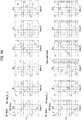
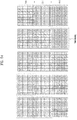
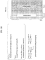
- the below table 28 and table 29 show FEC encoding parameters for a long FECBLOCK and a short FECBLOCK, respectively.
- Table 28 LDPC Rate N ldpc K ldpc K bch BCH error correction capability N bch -K bch 5/15 64800 21600 21408 12 192 6/15 25920 25728 7/15 30240 30048 8/15 34560 34368 9/15 38880 38688 10/15 43200 43008 11/15 47520 47328 12/15 51840 51648 13/15 56160 55968
- a 12-error correcting BCH code is used for outer encoding of the BBF.
- the BCH generator polynomial for short FECBLOCK and long FECBLOCK are obtained by multiplying together all polynomials.
- LDPC code is used to encode the output of the outer BCH encoding.
- Pldpc parity bits
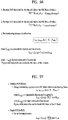
- the completed Bldpc (FECBLOCK) are expressed as follow Math figure.
- B ldpc I ldpc
- P ldpc i 0 , i 1 , ... , i K ldpc ⁇ 1 , p 0 , p 1 , ... , p N ldpc ⁇ K ldpc ⁇ 1
- This LDPC encoding procedure for a short FECBLOCK is in accordance with t LDPC encoding procedure for the long FECBLOCK, except replacing the table 30 with table 31, and replacing the addresses of parity check matrix for the long FECBLOCK with the addresses of parity check matrix for the short FECBLOCK.
- Table 31 Code Rate Q ldpc 5/15 30 6/15 27 7/15 24 8/15 21 9/15 18 10/15 15 11/15 12 12/15 9 13/15 6
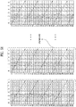
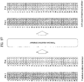
- FIG. 23 illustrates a bit interleaving according to an embodiment of the present invention.
- the outputs of the LDPC encoder are bit-interleaved, which consists of parity interleaving followed by Quasi-Cyclic Block (QCB) interleaving and inner-group interleaving. shows Quasi-Cyclic Block (QCB) interleaving and (b) shows inner-group interleaving.
- QQCB Quasi-Cyclic Block
- the FECBLOCK may be parity interleaved.
- the LDPC codeword consists of 180 adjacent QC blocks in a long FECBLOCK and 45 adjacent QC blocks in a short FECBLOCK.
- Each QC block in either a long or short FECBLOCK consists of 360 bits.
- the parity interleaved LDPC codeword is interleaved by QCB interleaving.
- the unit of QCB interleaving is a QC block.
- the QCB interleaving pattern is unique to each combination of modulation type and LDPC code rate.
- inner-group interleaving is performed according to modulation type and order ( ⁇ mod) which is defined in the below table 32.
- modulation type and order ( ⁇ mod) which is defined in the below table 32.
- the number of QC blocks for one inner-group, NQCB_IG is also defined.
- Modulation type ⁇ mod N QCB_IG QAM-16 4 2 NUC-16 4 4 NUQ-64 6 3 NUC-64 6 6 NUQ-256 8 4 NUC-256 8 8 NUQ-1024 10 5 NUC-1024 10 10
- the inner-group interleaving process is performed with NQCB_IG QC blocks of the QCB interleaving output.
- Inner-group interleaving has a process of writing and reading the bits of the inner-group using 360 columns and NQCB_IG rows.
- the bits from the QCB interleaving output are written row-wise.
- the read operation is performed column-wise to read out m bits from each row, where m is equal to 1 for NUC and 2 for NUQ.
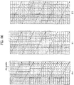
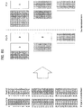
- FIG. 24 illustrates a cell-word demultiplexing according to an embodiment of the present invention.
- FIG. 24 shows a cell-word demultiplexing for 8 and 12 bpcu MIMO and (b) shows a cell-word demultiplexing for 10 bpcu MIMO.
- Each cell word (c0,1, c1,1, ..., c ⁇ mod-1,1) of the bit interleaving output is demultiplexed into (d1,0,m, d1,1,m..., d1, ⁇ mod-1,m) and (d2,0,m, d2,1,m..., d2, ⁇ mod-1,m) as shown in (a), which describes the cell-word demultiplexing process for one XFECBLOCK.
- the Bit Interleaver for NUQ-1024 is re-used.
- Each cell word (c0,1, c1,1, ..., c9,1) of the Bit Interleaver output is demultiplexed into (d1,0,m, d1,1,m..., d1,3,m) and (d2,0,m, d2,1,m..., d2,5,m), as shown in (b).
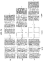
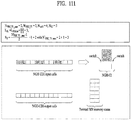
- FIG. 25 illustrates a time interleaving according to an embodiment of the present invention. to (c) show examples of TI mode.
- the time interleaver operates at the DP level.
- the parameters of time interleaving (TI) may be set differently for each DP.
- the parameter DP_NUM_BLOCK from the PLS2-DYN data is used to represent the number of XFECBLOCKs carried by one TI group of the DP.
- each TI group is a set of an integer number of XFECBLOCKs and will contain a dynamically variable number of XFECBLOCKs.
- the number of XFECBLOCKs in the TI group of index n is denoted by NxBLOCK_Group(n) and is signaled as DP_NUM_BLOCK in the PLS2-DYN data.
- NxBLOCK_Group(n) may vary from the minimum value of 0 to the maximum value NxBLOCK_Group_MAX (corresponding to DP_NUM_BLOCK_MAX) of which the largest value is 1023.
- Each TI group is either mapped directly onto one frame or spread over PI frames.
- Each TI group is also divided into more than one TI blocks(NTI), where each TI block corresponds to one usage of time interleaver memory.
- the TI blocks within the TI group may contain slightly different numbers of XFECBLOCKs. If the TI group is divided into multiple TI blocks, it is directly mapped to only one frame.
- There are three options for time interleaving (except the extra option of skipping the time interleaving) as shown in the below table 33. [Table 33] Modes Descriptions Option-1 Each TI group contains one TI block and is mapped directly to one frame as shown in (a).
- Each TI group contains one TI block and is mapped to more than one frame.
- DP_TI_TYPE '1'.
- Each TI group is divided into multiple TI blocks and is mapped directly to one frame as shown in (c).
- Each TI block may use full TI memory, so as to provide the maximum bit-rate for a DP.
- the TI memory stores the input XFECBLOCKs (output XFECBLOCKs from the SSD/MIMO encoding block).
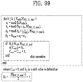
- input XFECBLOCKs are defined as d n , s , 0,0 , d n , s , 0,1 , ... , d n , s ,0 , N cells ⁇ 1 , d n , s , 1,0 , ... , d n , s ,1 , N cells ⁇ 1 , ... , d n , s , N xBLOCK _ TI n s ⁇ 1,0 , ... , d n , s , N xBLOCK _ TI n s ⁇ 1,0 , ... , d n , s , N xBLOCK _ TI n s ⁇ 1 , N cells ⁇ 1 , where d n
- the time interleaver will also act as a buffer for DP data prior to the process of frame building. This is achieved by means of two memory banks for each DP. The first TI-block is written to the first bank. The second TI-block is written to the second bank while the first bank is being read from and so on.
- the TI is a twisted row-column block interleaver.
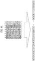
- FIG. 26 illustrates the basic operation of a twisted row-column block interleaver according to an embodiment of the present invention.
- Fig. 26 (a) shows a writing operation in the time interleaver and Fig. 26(b) shows a reading operation in the time interleaver
- the first XFECBLOCK is written column-wise into the first column of the TI memory, and the second XFECBLOCK is written into the next column, and so on as shown in (a).
- cells are read out diagonal-wise.
- N r cells are read out as shown in (b).
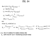
- the reading process in such an interleaving array is performed by calculating the row index R n,s,i , the column index C n,s,i , and the associated twisting parameter T n,s,i as follows expression.
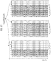
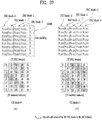
- FIG. 27 illustrates an operation of a twisted row-column block interleaver according to another embodiment of the present invention.
- the number of TI groups is set to 3.
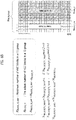
- FIG. 28 illustrates a diagonal-wise reading pattern of a twisted row-column block interleaver according to an embodiment of the present invention.
- FIG. 29 illustrates interlaved XFECBLOCKs from each interleaving array according to an embodiment of the present invention.
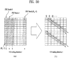
- FIG. 30 illustrates a time interleaving process according to an embodiment of the present invention.
- a timer interleaver (or time interleaver block) included in a broadcast signal transmitter interleaves cells belonging to a plurality of FEC blocks in the time domain and outputs the interleaved cells.
- TI group is a unit over which dynamic capacity allocation for a particular DP is carried out, made up of an integer, dynamically varying number of FEC blocks.
- Time interleaving block (TI block) is a set of cells within which time interleaving is carried out, corresponding to one use of the time interleaver memory.
- FEC block may be a set of encoded bits of a DP data or a set of number of cells carrying all the encoded bits.
- Each TI group is either mapped directly onto one frame or spread over multiple frames.
- Each TI group is also divided into more than one TI blocks, where each TI block corresponds to one usage of time interleaver memory.
- the TI blocks within the TI group may contain slightly different numbers of FECBLOCKs.
- the cells of the FEC blocks are transmitted being distributed in a specific period corresponding to a time interleaving depth through time interleaving, and thus diversity gain can be obtained.
- the time interleaver according to an embodiment of the present invention operates at the DP level.
- time interleaver can perform time interleaving including a writing operation of sequentially arranging different input FEC blocks in a predetermined memory and a diagonal reading operation of interleaving the FEC blocks in a diagonal direction.
- Time interleaving according to an embodiment of the present invention may be referred to as diagonal-type time interleaving or diagonal-type TI.
- the time interleaver will also act as a buffer for DP data prior to the process of frame building. This is achieved by means of two memory banks for each DP. The first TI-block is written to the first bank. The second TI-block is written to the second bank while the first bank is being read from and so on.
- the name of a device which performs time interleaving or the location or function of the device may be changed according to designer.
- a TI block according to an embodiment may be composed of Nc FEC blocks and the length of an FEC block may be assumed to be Nr ⁇ 1. Accordingly, a TI memory according to an embodiment of the present invention can have a size corresponding to an Nr ⁇ Nc matrix.
- the depth of time interleaving according to an embodiment of the present invention corresponds to the FEC block length.
- FIG. 30(a) shows a writing direction of time interleaving according to an embodiment of the present invention and FIG. 30(b) shows a reading direction of time interleaving according to an embodiment of the present invention.
- the broadcast signal transmitter can sequentially write input FEC blocks column-wise in a TI memory having a size of Nr ⁇ Nc (column-wise writing), as shown in FIG. 30(a) .
- the first FECBLOCK 0 is written column-wise into the first column of the TI memory, and the second FECBLOCK 1 is written in the next column, and so on.
- the broadcast signal transmitter according to an embodiment of the present invention can read the FEC blocks written column-wise in a diagonal direction, as shown in FIG. 30(b) . In this case, the broadcast signal transmitter according to an embodiment of the present invention can perform diagonal reading for one period.
- Diagonal reading of the next periods can be performed in order of 1, 2 and 3 in FIG. 30 (b) .
- FIG. 31 illustrates a time interleaving process according to another embodiment of the present invention.
- FIG. 31 shows another embodiment of the aforementioned writing operation and reading operation of the diagonal-type TI.
- One TI block according to an embodiment of the present invention includes 4 FEC blocks each of which may be composed of 8 cells. Accordingly, the TI memory has a size corresponding to an 8 ⁇ 4 (or 32 ⁇ 1) matrix and the column length and row length of the TI memory respectively correspond to the FEC block length (or time interleaving depth) and the number of FECs.
- TI input FEC blocks shown in the left part of FIG. 31 are FEC blocks sequentially input to the time interleaver.
- TI FEC blocks shown in the middle of FIG. 31 show n-th cell values of an i-th FEC block stored in the TI memory and TI memory indexes indicate the order of cells of FEC blocks stored in the TI memory.
- FIG. 31(a) illustrates TI writing operation.
- sequentially input FEC blocks can be sequentially written column-wise into the TI memory. Accordingly, cells of the FEC blocks are sequentially stored and written with TI memory indexes.
- FIG. 31(b) illustrates TI reading operation.
- cell values stored in the TI memory can be diagonally read and output in the order of memory indexes 0, 9, 18, 27, ....
- a position of cell to start diagonal-wise reading or diagonal-wise reading pattern may be be changed according to designer.
- TI output FEC blocks shown in the right part of FIG. 31 sequentially indicate cell values output through diagonal-type TI according to an embodiment of the present invention.
- TI output memory indexes correspond to the cell values output through diagonal-type TI.
- the time interleaver can perform diagonal-type TI by sequentially generating TI output memory indexes for sequentially input FEC blocks.
- FIG. 32 illustrates a process of generating TI output memory indexes according to an embodiment of the present invention.
- the time interleaver can perform diagonal-type TI by sequentially generating TI output memory index values for sequentially input FEC blocks.
- FIG. 32 (a) illustrates a process of generating diagonal-type TI memory indexes for the above-described sequentially input FEC blocks and FIG. 32 (b) shows equations representing the memory index generation process.
- a time deinterleaver (or time deinterleaver block) included in a broadcast signal receiver according to an embodiment of the present invention can perform inverse processing of the aforementioned diagonal-type TI. That is, the time deinterleaver according to an embodiment of the present invention can perform time deinterleaving by receiving FEC blocks on which diagonal-type TI has been performed, writing the FEC blocks diagonal-wise in a TI memory and then sequentially reading the FEC blocks.
- Time deinterleaving according to an embodiment of the present invention may be referred to as diagonal-type TDI or diagonal-type time deinterleaving.
- the name of a device performing time deinterleaving or the location or function of the device may be changed according to designer.
- FIG. 33 illustrates a time deinterleaving process according to an embodiment of the present invention.
- the time deinterleaving process shown in FIG. 33 corresponds to inverse processing of the time interleaving process shown in FIG. 30 .
- FIG. 33 (a) shows a writing direction of time deinterleaving according to an embodiment of the present invention
- FIG. 33 (b) shows a reading direction of time deinterleaving according to an embodiment of the present invention.
- the time deinterleaver can receive FEC blocks on which diagonal-type TI has been performed from a transmitter and diagonally write the FEC blocks into a TDI (time deinterleaver) memory (diagonal-wise writing).
- TDI time deinterleaver
- the time deinterleaver according to an embodiment of the present invention can perform diagonal writing for one period.
- diagonal reading of the first period starts at (0,0) of the memory matrix and is performed until the cell of the lowest row is read.
- Diagonal writing of respective periods can be performed in order of 1, 2 and 3 in FIG. 33 (b) .
- the time deinterleaver according to an embodiment of the present invention can sequentially read diagonally written FEC blocks column-wise (column-wise reading).
- FIG. 34 illustrates a time deinterleaving process according to another embodiment of the present invention.
- the time deinterleaving process shown in FIG. 34 is the inverse of the time interleaving process shown in FIG. 31 .
- One TI block according to an embodiment of the present invention includes 4 FEC blocks each of which may be composed of 8 cells. Accordingly, the TI memory has a size corresponding to an 8 ⁇ 4 (or 32 ⁇ 1) matrix and the column length and row length of the TI memory respectively correspond to the FEC block length (or time interleaving depth) and the number of FECs.
- TDI input FEC blocks shown in the left part of FIG. 34 represent cells of FEC blocks sequentially input to the time deinterleaver and TDI input memory indexes correspond to the cells of the sequentially input FEC blocks.
- TDI FEC blocks shown in the middle of FIG. 34 show n-th cell values of an i-th FEC block stored in the TDI memory and TDI memory indexes indicate the order of cells of FEC blocks stored in the TDI memory.
- FIG. 34 (a) illustrates TDI writing operation.
- sequentially input FEC blocks can be sequentially written to the TDI memory diagonal-wise. Accordingly, the cells of the input FEC blocks are sequentially stored and written with TDI memory indexes.
- FIG. 34 (b) illustrates TDI reading operation.
- cell values stored in the TDI memory can be column-wise read and output in the order of memory indexes 0, 1, 2, 3, ....
- TDI output FEC blocks shown in the right part of FIG. 34 sequentially indicate cell values output through time deinterleaving according to an embodiment of the present invention.
- TDI output memory indexes correspond to the cell values output through time deinterleaving according to an embodiment of the present invention.
- the time deinterleaver can perform diagonal-type TDI by sequentially generating TDI output memory index values for sequentially input FEC blocks.
- FIG. 35 illustrates a process of generating TDI output memory indexes according to an embodiment of the present invention.
- the time deinterleaver can perform diagonal-type TDI by sequentially generating TDI output memory index values for sequentially input FEC blocks.
- FIG. 35 (a) illustrates a process of generating diagonal-type TDI memory indexes for the above-described sequentially input FEC blocks and FIG. 32 (b) shows equations representing the memory index generation process.
- the broadcast signal transmitter may be a variable data-rate system in which a plurality of FEC blocks is packed and configured as a plurality of TI blocks and transmitted.
- TI blocks may have different numbers of FEC blocks included therein.
- FIG. 36 is a conceptual diagram illustrating a variable data-rate system according to an embodiment of the present invention.
- FIG. 36 shows TI blocks mapped to one signal frame.
- variable data-rate system as a broadcast signal transmitter can pack a plurality of FEC blocks as a plurality of TI blocks and transmit the TI blocks.
- the TI blocks may have different numbers of FEC blocks included therein.
- one signal frame may include NTI_NUM TI blocks each of which may include NFEC_NUM FEC blocks.
- the respective TI blocks may have different numbers of FEC blocks included therein.
- time interleaving which can be performed in the aforementioned variable data-rate system.
- This time interleaving process is another embodiment of the above-described time interleaving process and has the advantage that the time interleaving process is applicable to a case in which the broadcast signal receiver has a single memory.
- Time interleaving according to another embodiment of the present invention may be referred to as the aforementioned diagonal-type TI and may be performed in the time interleaver included in the broadcast signal transmitter according to an embodiment of the present invention.
- time deinterleaving may be referred to as diagonal-type TDI and may be performed in the time deinterleaver in the broadcast signal receiver according to an embodiment of the present invention.
- the name of a device which performs time interleaving or time deinterleaving or the location or function of the device may be changed according to designer.
- a description will be given of detailed time interleaving and time deinterleaving operations.
- the broadcast signal transmitter according to the present invention determines a single diagonal-type TI method and equally applies the determined diagonal-type TI method to all TI blocks according to an embodiment of the present invention.
- the broadcast signal transmitter according to an embodiment of the present invention can sequentially deinterleave a plurality of TI blocks using a single memory.
- the broadcast signal transmitter can determine the diagonal-type TI method applied to all TI blocks on the basis of a TI block including a maximum number of FEC blocks within one signal frame.
- the broadcast signal transmitter can determine the diagonal-type TI method applied to all TI blocks on the basis of a TI block including a medium number of FEC blocks within one signal frame or an arbitrary TI block within one signal frame. It can be determined according to designer.
- the broadcast signal transmitter may monitor generated memory indexes and determine whether to apply the memory indexes according to an embodiment of the present invention.
- the broadcast signal transmitter ignores TI memory indexes greater than the number of cells according to an embodiment of the present invention.
- the broadcast signal transmitter may sequentially apply the diagonal-type TI method to TI blocks from a TI block including a small number of FEC blocks in order of the number of FEC blocks according to an embodiment of the present invention. Accordingly, the broadcast signal receiver according to an embodiment of the present invention can simply operate the single memory, which will be described in detail later.
- FIG. 37 illustrates a time interleaving process according to another embodiment of the present invention.
- FIG. 37 shows an embodiment of applying diagonal-type TI in a variable data-rate system.
- FIG. 37(a) illustrates a process of applying diagonal-type TI to TI block 0 including 4 FEC blocks and FIG. 37(b) illustrates a process of applying diagonal-type TI to TI block 1 including 5 FEC blocks.
- TI FEC blocks represent FEC blocks included in each TI block and cell values corresponding to the FEC blocks.
- TI memory indexes indicate memory indexes corresponding to cell values included in TI blocks.
- each FEC block may include 8 cells.
- the broadcast signal transmitter can determine a diagonal-type TI method which is equally applied to two TI blocks. Since the diagonal-type TI method according to an embodiment of the present invention is determined on the basis of a TI block including a maximum number of FEC blocks within one frame, as described above, diagonal-type TI is determined based on TI block 1 in the case of FIG. 37 . Accordingly, the TI memory can have a size corresponding to an 8 ⁇ 5 (40 ⁇ 1) matrix.
- the broadcast signal transmitter can add (pad) a virtual FEC block 23000 having a value of 0 to TI block 0 and column-wise write cells corresponding to the virtual FEC block 23000 into the TI memory.
- the position to which the virtual FEC block is added can be determined according to designer.
- the broadcast signal transmitter can diagonally read cells written in the TI memory.
- the last column corresponds to the virtual FEC block, it is possible to perform reading operation while ignoring the cells corresponding to the virtual FEC block.
- the broadcast signal transmitter according to an embodiment of the present invention can perform column-wise writing and diagonal reading for TI block 1 according to the aforementioned method, as shown in FIG. 37 (b) .
- diagonal-type TI since diagonal-type TI according to an embodiment of the present invention is preferentially applied to a TI block including a smaller number of FEC blocks, diagonal-type TI can be applied to TI block 1 first in the case of FIG. 37 .
- FIG. 38 illustrates a process of generating TI output memory indexes according to another embodiment of the present invention.
- FIG. 38 shows a process of generating TI output memory indexes for the above-described two TI blocks (TI block 0 and TI block 1) and TI output FEC blocks corresponding to TI output memory indexes.
- Blocks corresponding to TI output memory indexes represent a process of generating TI output memory indexes and TI output FEC blocks represent cell values of FEC blocks corresponding to the generated TI output memory indexes.
- FIG. 38 (a) illustrates a process of generating TI output memory indexes of TI block 0.
- the broadcast signal transmitter when the number of TI memory indexes exceeds the number of cells of TI block 0, the broadcast signal transmitter according to an embodiment of the present invention can ignore TI memory indexes 32 to 39 corresponding to cells included in a virtual FEC block. This operation may be referred to as skip operation. Consequently, final output memory indexes for which reading can be performed, except for the skipped TI memory indexes, are generated as shown in FIG. 38 (a) . Cell values of output FEC blocks corresponding to the final output memory indexes are shown in the lower part of FIG. 38 (a) .
- FIG. 38 (b) illustrates a process of generating TI output memory indexes of TI block 1. In the case of TI block 1, skip operation is not applied. The process corresponds to the aforementioned process.
- the following equation represents the output memory index generation process for performing diagonal-type TI applicable in the aforementioned variable data-rate system.
- FIG. 39 is a flowchart illustrating a TI memory index generation process according to an embodiment of the present invention.
- the time interleaver can perform diagonal-type TI by sequentially generating TI output memory indexes for sequentially input FEC blocks.
- the broadcast signal transmitter according to an embodiment of the present invention may set initial values (S25000). That is, the broadcast signal transmitter according to an embodiment of the present invention can determine a diagonal-type TI method applied to all TI blocks on the basis of a TI block including a maximum number of FEC blocks.
- the broadcast signal transmitter according to an embodiment of the present invention may generate temporal TI memory indexes (S25100). That is, the broadcast signal transmitter according to an embodiment of the present invention can add (pad) a virtual FEC block to TI blocks having numbers of FEC blocks less than a predetermined TI memory index and write cells corresponding to TI blocks into a TI memory.
- the broadcast signal transmitter according to an embodiment of the present invention may evaluate availability of the generated TI memory indexes (S25200). That is, the broadcast signal transmitter according to an embodiment of the present invention can diagonally read the cells written in the TI memory. In this case, cells corresponding to the virtual FEC block can be skipped and reading can be performed.
- broadcast signal transmitter may generate final TI memory indexes (S25300).
- the flowchart of FIG. 39 corresponds to the process of generating TI output memory indexes, described with reference to FIGS. 36 , 37 and 38 , and may be modified according to designer.
- FIG. 40 illustrates a time deinterleaving process according to another embodiment of the present invention.
- the time deinterleaving process shown in FIG. 40 is the inverse of the time interleaving process described with reference to FIGS. 23 , 24 and 25 .
- time deinterleaving according to another embodiment of the present invention can be applied to a case in which the broadcast signal receiver uses a single memory.
- the reading and writing operations for the interleaved TI blocks should be accomplished simultaneously.
- the TDI procedure can be expressed as a closed-form, which leads to the efficient TDI implementation.
- Time deinterleaving according to another embodiment of the present invention may be performed through four steps.
- FIG. 40 (a) illustrates the first step (step 1) of time deinterleaving.
- the cell value corresponding to a memory index ignored during TI processing is set to zero (or an identification value). That is, the blocks shown in the upper part of FIG. 40 (a) represent cell values of output FEC blocks corresponding to final output memory indexes of TI block 0 and the blocks shown in the lower part of FIG. 40 (a) represent cell values of FEC blocks, which are generated by setting cell values corresponding to memory indexes skipped in skip operation to zero.
- step 2 After step 1, output of step1 is written to the single-memory of size 8 x 5.
- the writing direction is identical to the reading direction in TI processing.
- the broadcast signal receiver according to an embodiment of the present invention can perform diagonal writing operation as the first inverse process of TI of the transmitter for the first input TI block. That is, diagonal writing can be performed in a direction opposite to the direction of diagonal reading performed by the transmitter.
- FIG. 40 (b) illustrates the third step (step 3) of time deinterleaving.
- Blocks corresponding to TDI FEC blocks represent cell values of input FEC blocks.
- Blocks corresponding to TDI memory indexes represent TDI memory indexes corresponding to cell values of FEC blocks.
- step 2 column-wise reading operation is performed in the same direction as the writing direction in TI processing. At this time, if the reading value is zero (or an identification value), it is ignored (skip operation). This skip operation corresponds to the aforementioned skip operation performed in the broadcast signal transmitter.
- C cnt,j counter of actual TDI output memory-index for the jth TI block ⁇ j ⁇ 1 k : temporal TDI output memory-index for the jth TI block M ⁇ j ⁇ 1 k : the reserved cell value at ⁇ j ⁇ 1 k ⁇ j ⁇ 1 k : actual TDI output memory-index for the jth TI block
- the "if" statement in the above equation represents the aforementioned skip operation, that is, the process of ignoring indexes when the indexes corresponding cell values stored in the TDI output memory are 0 (or an arbitrary value indicating that the indexes are forcibly inserted).
- FIG. 41 illustrates a time deinterleaving process according to another embodiment of the present invention.
- the broadcast signal receiver according to an embodiment of the present invention can perform time deinterleaving using a single memory. Accordingly, the broadcast signal receiver according to an embodiment of the present invention can read TI block 0 and write TI block 1 simultaneously in the fourth step (step 4).
- FIG. 41 (a) shows TDI FEC blocks of TI block 1 written simultaneously with reading of TI block 0 and TDI memory indexes.
- the writing operation can be performed in a direction opposite to the direction of diagonal reading performed in the broadcast signal receiver, as described above.
- FIG. 41 (b) shows output TDI memory indexes according to writing of TI block 1.
- arrangement of the stored FEC blocks within TI block 1 may differ from arrangement of the FEC blocks stored in the TI memory of the broadcast signal transmitter. That is, inverse processes of the writing and reading operations performed in the broadcast signal transmitter may not be equally applied in case of a single memory.
- FIG. 42 illustrates a writing method according to an embodiment of the present invention.
- the present invention provides a method of writing FEC blocks into a TI memory in a matrix form.
- the writing method illustrated in FIG. 42 can be equally applied to the aforementioned time interleaving and time deinterleaving processes according to an embodiment of the present invention.
- FIG. 42 (a) illustrates a case in which cells of FEC blocks are written to the memory in a vector form, which corresponds to the aforementioned writing method.
- FIG. 42 (b) illustrates a case in which cells of FEC blocks are written to the memory in a matrix form. That is, the FEC blocks can be written in the form of an m ⁇ n matrix.
- the matrix size can be changed according to designer and the inverse processes of the writing and reading processes performed in the broadcast signal transmitter can be equally applied to a case in which the broadcast signal receiver uses a single memory.
- FIG. 43 is a flowchart illustrating a process of generating TDI memory indexes according to an embodiment of the present invention.
- the time deinterleaver can perform diagonal-type TI by sequentially generating TI output memory indexes for sequentially input FEC blocks.
- the broadcast signal receiver according to an embodiment of the present invention may set initial values (S29000). That is, in the broadcast signal receiver according to an embodiment of the present invention, the cell value corresponding to a memory index ignored during TI processing is set to zero (or an identification value) using TI rue before TDI processing for the first TI block.
- the broadcast signal receiver may generate temporal TI memory indexes (S29100).
- the broadcast signal receiver may perform diagonal writing operation as the first inverse process of TI of the transmitter for the first input TI block.
- the broadcast signal transmitter may evaluate the generated TI memory indexes (S29200).
- the broadcast signal transmitter may generate final TI memory indexes (S29300).
- the flowchart shown in FIG. 43 corresponds to the process of generating TDI output memory indexes, described with reference to FIGS. 30 , 31 and 32 , and may be changed according to designer.
- FIG. 44 illustrates a time interleaving process according to another embodiment of the present invention.
- a timer interleaver (or time interleaver block) included in a broadcast signal transmitter interleaves cells belonging to a plurality of FEC blocks in the time domain and outputs the interleaved cells.
- the time interleaver according to another embodiment of the present invention can perform time interleaving including a writing operation of sequentially arranging different input FEC blocks in a predetermined memory and a diagonal reading operation of interleaving the FEC blocks in a diagonal direction.
- the time interleaver according to an embodiment of the present invention can change the size of a diagonal slope of a reading direction and perform time interleaving while reading different FEC blocks in a diagonal direction. That is, the time interleaver according to an embodiment of the present invention can change a TI reading pattern.
- Time interleaving according to an embodiment of the present invention may be referred to as diagonal-type time interleaving or diagonal-type TI or flexible diagonal-type time interleaving or flexible diagonal-type TI.
- FIG. 44(a) shows a writing direction of time interleaving according to an embodiment of the present invention
- FIG. 44(b) shows a reading direction of time interleaving according to an embodiment of the present invention.
- the broadcast signal transmitter according to an embodiment of the present invention can sequentially write input FEC blocks column-wise in a TI memory having a size of Nr ⁇ Nc (column-wise writing), as shown in FIG. 44(a) .
- the details are same as described in FIG. 30 .
- the broadcast signal transmitter according to an embodiment of the present invention can read the FEC blocks written column-wise in a diagonal direction, as shown in FIG. 44(b) .
- the broadcast signal transmitter according to an embodiment of the present invention can perform diagonal reading for one period.
- the diagonal slope of the TI reading direction may be differently set for respective TI blocks or super frame units.
- N r cells are read out as shown in FIG. 44(b) .
- the diagonal slope of the TI reading direction may be differently set for respective TI blocks or super frame units.
- FIG. 44 illustrates the case in which the diagonal slope of the TDI writing direction is a diagonal slope-1 or a diagonal slope-2.
- the TI diagonal reading can be performed from a memory matrix (0,0) for a first period according to the diagonal slope of the TI reading direction until cells contained in a specific FEC block are read according to a specific shifting value. This can be changed according to intention of the designer.
- FIG. 45 illustrates diagonal slopes according to an embodiment of the present invention.
- FIG. 45 illustrates a diagonal slope-1 to a diagonal slope-6 when the size of Nc of a TI block is 7 and the size of Nr is 11 according to an embodiment of the present invention.
- the size of the diagonal slope according to an embodiment of the present invention can be changed according to intention of the designer.
- the t time interleaver can change the size of the diagonal slope of the TI reading according to the size of a maximum TI memory size and change a TI reading pattern.
- the TI reading pattern can be changed in a superframe unit as a set of signal frames that are consecutively transmitted in a time axis and information about the TI reading pattern may be transmitted through the aforementioned static PLS signaling data.
- the time interleaving process described above with reference to FIG. 31 and the TI output memory index generation process described with reference to FIG. 32 can be equally applied to diagonal-type TI using diagonal slopes of TI reading shown in FIG. 45 .
- the time interleaver according to an embodiment of the present invention can perform diagonal-type TI by sequentially generating TI output memory index values for sequentially input FEC blocks, as described above with reference to FIG. 31 .
- Equation 15 represents a process for generation of a memory index for the diagonal-type TI when the slope values of the various TI readings described with reference to FIG. 45 are set.
- r k mod k N r
- N c ⁇ k N r c k + r k , for 0 ⁇ k ⁇ N ⁇ 1
- a time deinterleaver (or time deinterleaver block) included in a broadcast signal receiver can perform inverse processing of the aforementioned diagonal-type TI. That is, the time deinterleaver according to an embodiment of the present invention can perform time deinterleaving by receiving FEC blocks on which diagonal-type TI has been performed, writing the FEC blocks diagonal-wise in a TI memory and then sequentially reading the FEC blocks.
- Time deinterleaving according to an embodiment of the present invention may be referred to as diagonal-type TDI or diagonal-type time deinterleaving or flexible diagonal-type time deinterleaving or flexible diagonal-type TDI.
- the name of a device performing time deinterleaving or the location or function of the device may be changed according to designer.
- FIG. 46 illustrates a time deinterleaving process according to an embodiment of the present invention.
- the time deinterleaving process shown in FIG. 46 corresponds to inverse processing of the time interleaving process shown in FIG. 44 .
- FIG. 46 (a) shows a writing direction of time deinterleaving according to an embodiment of the present invention
- FIG. 46 (b) shows a reading direction of time deinterleaving according to an embodiment of the present invention.
- the time deinterleaver can receive FEC blocks on which diagonal-type TI has been performed from a transmitter and diagonally write the FEC blocks into a TDI (time deinterleaver) memory (diagonal-wise writing).
- TDI time deinterleaver
- the time deinterleaver according to an embodiment of the present invention can perform diagonal writing for one period.
- diagonal slope values of a TDI writing direction may be differently set for respective TDI block and super frame unit.
- FIG. 46 illustrates the case in which the diagonal slope of the TDI writing direction is a diagonal slope-1 or a diagonal slope-2.
- diagonal reading of the first period starts at (0,0) of the memory matrix and is performed until the cell of the lowest row is read.
- Diagonal writing of respective periods can be performed in order of 12and 3in FIG. 46(b) .
- the TDI diagonal writing can be performed from a memory matrix (0,0) for a first period until cells contained in a specific FEC block are read according to a specific shifting value. This can be changed according to intention of the designer.
- the time deinterleaver can sequentially read diagonally written FEC blocks column-wise (column-wise reading).
- the time deinterleaving process described above with reference to FIG. 46 can be equally applied to diagonal-type TI using the diagonal slopes of TI reading shown in FIG. 45 .
- the time deinterleaver can perform diagonal-type TDI by sequentially generating TDI output memory index values for sequentially input FEC blocks.
- FIG. 47 illustrates a process of generating TDI output memory indexes according to an embodiment of the present invention.
- the time deinterleaver can perform diagonal-type TDI by sequentially generating TDI output memory index values for sequentially input FEC blocks.
- FIG. 47(a) illustrates a process of generating diagonal-type TDI memory indexes for the above-described sequentially input FEC blocks and FIG. 47(b) shows equations representing the memory index generation process.
- Equation 16 represents a process for generation of a TDI output memory index for the diagonal-type TDI when diagonal slope values of the various TI readings described with reference to FIG. 45 are set.
- the broadcast signal transmitter may be a variable data-rate system in which a plurality of FEC blocks is packed and configured as a plurality of TI blocks and transmitted.
- TI blocks may have different numbers of FEC blocks included therein.
- FIG. 48 is a conceptual diagram illustrating a variable data-rate system according to an embodiment of the present invention.
- One transmission superframe may include NIF_NUM interleaving frames (IFs) and each IF may include NFEC_NUM FEC blocks.
- IFs NIF_NUM interleaving frames
- each IF may include NFEC_NUM FEC blocks.
- the number of FEC blocks included in each IF may be varied.
- An IF according to an embodiment of the present invention may be defined as a block for timing interleaving and may be referred to as the aforementioned TI block.
- the broadcast signal transmitter virtual FEC blocks can be added (zero padding) and diagonal-type TI can be performed. Since the added virtual FEC blocks include cells having zero value, the broadcast signal transmitter according to the present invention may skip or ignore the added virtual FEC blocks. This operation may be referred to as skip operation. The skip operation will be described in detail later.
- the following equations represent the aforementioned process of determining a diagonal-type TI method applied to all IFs. Specifically, the following equation represents a process of determining the sizes of a column and a row with respect to IF including a maximum number of FEC blocks in one superframe in determination of a diagonal-type TI method.
- diagonal-type TI is applied in the variable data-rate system described with reference to FIG. 37 can be equally applied to an IF including a plurality of FEC blocks.
- the IFs are included in one super frame.
- time deinterleaving corresponding to the diagonal-type TI method can be applied to a case in which the broadcast signal receiver uses a single memory.
- process of generating a TI output memory index can be equally applied to an IF including a plurality of FEC blocks.
- Equation 18 the "if" statement represents the aforementioned skip operation.
- Equation 18 above represents a process for generation of an output memory index for the aforementioned diagonal type TI of the diagonal slope. Accordingly, a diagonal slope value is defined as one variable.
- FIG. 39 can be equally applied to an IF including a plurality of FEC blocks.
- time deinterleaving process according to another embodiment of the present invention can be equally applied to the IF including a plurality of FEC blocks.
- C cnt,j counter of actual TDI output memory-index for the jth IF ⁇ j ⁇ 1 k : the reserved cell value at ⁇ j ⁇ 1 k M ⁇ j ⁇ 1 k : temporal TDI output memory-index for the jth IF ⁇ j ⁇ 1 k : actual TDI output memory-index for the jth IF
- Equation 19 represents a process of generation of a TDI memory index for time interleaving corresponding to the aforementioned diagonal type TI according to a diagonal slope.
- the writing method according to an embodiment of the present invention can be equally applied an IF including a plurality of FEC blocks.
- FIG. 49 is a flowchart illustrating a process of generating TDI memory indexes according to an embodiment of the present invention.
- the time deinterleaver can perform diagonal-type TI by sequentially generating TI output memory indexes for sequentially input FEC blocks.
- the broadcast signal receiver according to an embodiment of the present invention may set initial values (S30000). That is, in the broadcast signal receiver according to an embodiment of the present invention, the cell value corresponding to a memory index ignored during TI processing is set to zero (or an identification value) using TI rue before TDI processing for the first IF.
- the broadcast signal receiver may calculate a diagonal slope to be used for TDI processing (S30100).
- the broadcast signal receiver may generate temporal TI memory indexes (S30200).
- the broadcast signal receiver may perform diagonal writing operation as the first inverse process of TI of the transmitter for the first input IF.
- the broadcast signal transmitter may evaluate the generated TI memory indexes (S30300).
- the broadcast signal transmitter may generate final TI memory indexes (S30400).
- the flowchart shown in FIG. 49 corresponds to the process of generating TDI output memory indexes, described with reference to FIGS. 27 , 28 and 29 , and may be changed according to designer.
- FIG. 50 illustrates IF-by-IF TI pattern variation according to an embodiment of the present invention.
- the broadcast signal transmitter (or a time interleaver) according to an embodiment of the present invention may differently apply a diagonal slope in superframe units or IF units.
- FIG. 50 illustrates an embodiment in which diagonal slopes are differently applied to respective IFs and TI patterns are changed and, that is, an embodiment in which the diagonal slopes are differently applied to the respective IFs according to the cases in which the number of FEC blocks contained in an IF is an even number and an odd number. This is because, when the number of the FEC blocks is an even number, a diagonal slope for reducing an interleaving depth may be present.
- FIG. 50 illustrates an embodiment in which the number of IFs included in one superframe is 6 and the length of an FEC block included in each IF, Nr is 11 and, that is, an embodiment in which a diagonal slope is determined to be applied when the number of FEC blocks is 7.
- FIG. 50(a) illustrates an embodiment in which the number of FEC blocks included in each IF is an odd number, that is, 7.
- the time interleaver according to an embodiment of the present invention may randomly select the diagonal slopes (in an order of diagonal slopes 1, 4, 3, 6, 2, and 5) and apply to 6 IFs so as not to repeat the diagonal slopes described with reference to FIG. 45 .
- FIG. 50(b) illustrates an embodiment in which the number of FEC blocks included in each IF is an even number, that is, 6 and, that is, an embodiment in which the diagonal slope values described with reference to FIG. 45 is set to be applied to the case in which the number of FEC blocks is 7.
- the time interleaver may assume that each IF includes 7 FEC blocks and, that is, add the aforementioned virtual FEC block and apply a random diagonal slope to perform diagonal reading (in an order of diagonal slopes 1, 4, 3, 6, 2, and 5).
- cells of the virtual FEC may be disregarded via a skip operation.
- the broadcast signal transmitter may select an IF having a largest number of FEC blocks in one superframe and determine Nc.
- a process for determination of Nc is the same as in 17 above.
- the broadcast signal transmitter determines whether the determined Nc is an even or odd number.
- Equation 21 represents a process of generation of a diagonal slope to be used in each IF using a quadratic polynomial (QP) scheme.
- the QP scheme may correspond to an embodiment of the present invention and may be replaced with a primitive polynomial (PP) scheme. This can be changed according to intention of the designer.
- PP polynomial
- Equation 22 represents a process of sequentially generating a diagonal slope.
- the broadcast signal transmitter according to an embodiment of the present invention may perform time interleaving in consideration of variables generated via the processes of Equations 20 to 22 above.
- a process of generation of a TI output memory output memory index of the broadcast signal transmitter according to an embodiment of the present invention may be represented according to Equation 18 above.
- Equation 21 above may include the diagonal slope generated according to Equations 21 and 22 above as a main variable.
- the skip operation described with reference to Equation 21 above can be applied irrespective of whether the length of Nc is an even or odd number.
- the broadcast signal receiver according to an embodiment of the present invention can perform time interleaving so as to correspond to the aforementioned broadcast signal transmitter.
- a process of generation of a TDI output memory index of the broadcast signal receiver according to an embodiment of the present invention can be represented according to Equation 19 above.
- Equation 19 above may include the diagonal slope generated via the generating processes represented according to Equations 21 to 22 as a main variable.
- the skip operation described with reference to Equation 19 above can be applied irrespective of whether the length of Nc is an even or odd number.
- the information associated with the TI pattern may be transmitted via the aforementioned static PLS signaling data.
- Information indicating whether the TI pattern is changed may be represented as TI_Var and may have a one bit size. When TI_Var has a value 0, this means that the TI pattern is not changed. Accordingly, the broadcast signal receiver according to an embodiment of the present invention may determine a variable ST as 1 that is a default value. When TI_Var has a value 1, this means that the TI pattern is changed. In this case, the broadcast signal receiver according to an embodiment of the present invention may determine the variable ST as ST,j.
- the following equations is another embodiment of the equation 18 and represent the output memory index generation process for performing diagonal-type TI applicable in the aforementioned variable data-rate system.
- Equation 19 represent the TDI memory index generation process which is applied to IF including a plurality of FEC blocks.
- the below equation represents a processing of calculating an optimum shift value to provide the maximum performance in a burst channel.
- the shift value according to an embodiment of the present invention is used to determine a TI pattern of reading operation and can be equal to a value of the diagonal slope.
- the maximum value of row for TI may be 8 and the maximum number of column for TI may be 5.
- the optimum shift value can be 2.
- the maximum value of row for TI may be 8 and the maximum number of column for TI may be 5.
- the optimum shift value can be 3.
- FIG. 51 illustrates IF interleaving according to an embodiment of the present invention.
- IF interleaving according to an embodiment of the present invention is for a variable data-rate transmission system, and maintains the same pattern for the aforementioned diagonal-wise reading and performs a skip operation for virtual FEC blocks in an embodiment.
- IF interleaving (or twisted block interleaving) can be determined and applied.
- the receiver can perform IF deinterleaving using a single memory.
- the time interleaver according another embodiment of the present invention may include a convolutional interleaver and a block interleaver.
- the convolutional interleaver according to an embodiment of the present invention can perform inter-frame interleaving which is applied to between different TI blocks.
- the block interleaver according to an embodiment of the present invention can perform intra-frame interleaving which is applied in a TI block. Also, The block interleaver according to an embodiment of the present invention can perform an interleaving described in FIG. 30- FIG. 50 .
- the time interleaver according another embodiment of the present invention can increase time diversity by using the concatenated inter-frame interleaving and intar-frame intereavling. The details will be described.
- CI convolutional interleaving
- CI can be defined as interleaving of IFs.
- Each IF can be divided into interleaving units (IUs).
- start-skip operation and stop-skip operation can be applied.
- FIG. 52 illustrates CI according to an embodiment of the present invention.
- FIG. 52 shows CI in consideration of constant data-rate transmission.
- Blocks shown in the left part of the figure indicate IFs corresponding to CI input.
- the figure shows an embodiment in which 4 IFs are present.
- a block shown in the middle part of the figure indicates a register block in a convolutional interleaver for performing CI.
- the size of the register block according to an embodiment of the present invention can be determined using the aforementioned IU as a basic unit.
- the figure shows the register block when the number of IUs is 3.
- Blocks shown in the right part of the figure indicate IFs corresponding to CI output.
- some IUs in the register block are not completely filled, and thus a dummy IU may be output.
- the aforementioned start-skip operation can be performed.
- a dummy IU according to an embodiment of the present invention may be referred to as a virtual IU.
- a dummy IU may be output. For this dummy IU, end-skip operation can be performed.
- FIG. 53 illustrates CI according to another embodiment of the present invention.
- FIG. 53 shows CI considering variable data-rate transmission.
- Blocks shown in the left of the figure indicate IFs corresponding to CI input.
- the figure illustrates an embodiment in which the number of IFs is 3.
- An IF size according to an embodiment of the present invention is determined by a maximum IF size, and the determined IF size can be maintained in an embodiment. Further, a memory of CI can be determined according to the IU size.
- the right of the figure shows a register block in a convolutional interleaver for performing CI.
- the size of the register block for CI can be determined on the basis of a largest IU from among IUs obtained when each IF block is divided into IUs. This figure shows a case in which the number of IUs is 3.
- a dummy IU may be output. For this dummy IU, end-skip operation can be performed.
- FIG. 54 illustrates output IFs of CI according to an embodiment of the present invention.
- FIG. 54 shows IFs corresponding to output of CI described with reference to FIG. 53 .
- Blocks indicated by x in IUs are virtual IUs and can be ignored by the aforementioned start-skip operation and end-skip operation.
- FIG. 55 illustrates a time interleaver according to another embodiment of the present invention.
- the time interleaver according to another embodiment of the present invention may include a convolutional interleaver and a block interleaver.
- the convolutional interleaver according to an embodiment of the present invention can perform CI described above with reference to FIGS. 51 , 52 and 53 and the block interleaver according to an embodiment of the present invention can perform interleaving, described with reference to FIGS. 26 to 50 , on IFs output from the convolutional interleaver.
- the block interleaver according to an embodiment of the present invention may be referred to as a twisted block interleaver.
- the positions and names of the convolutional interleaver and the block interleaver may be changed according to intention of the designer.
- FIG. 56 illustrates operation of the block interleaver according to an embodiment of the present invention.
- the block interleaver according to an embodiment of the present invention can perform interleaving, described above with reference to FIGS. 26 to 50 , on IFs output from the convolutional interleaver.
- the block interleaver according to an embodiment of the present invention can perform start-skip operation and end-skip operation on CI output and continuously stack data in IUs in the vertical direction so as to obtain IF blocks.
- the present figure shows a case in which 3 IFs are acquired. Subsequently, the block interleaver can perform the aforementioned diagonal reading of the IF blocks. As described above, cells of a virtual FEC block in the IF blocks can be ignored by skip operation.
- FIG. 57 illustrates operation of the block interleaver according to another embodiment of the present invention.
- the block interleaver can perform start-skip operation and end-skip operation on CI output and continuously stack data in IUs in the horizontal direction so as to obtain IF blocks. Subsequently, the block interleaver can perform diagonal reading of the IF blocks. As described above, cells of a virtual FEC block in the IF blocks can be ignored by skip operation.
- FIG. 58 illustrates a time deinterleaver according to another embodiment of the present invention.
- the time deinterleaver according to another embodiment of the present invention may include a block deinterleaver and a convolutional deinterleaver.
- the time deinterleaver according to another embodiment of the present invention can perform operation corresponding to a reverse of operation of the time interleaver described above with reference to FIG. 56 . That is, the block deinterleaver according to an embodiment of the present invention can perform a reverse of interleaving described above with reference to FIGS. 26 to 50 and the convolutional deinterleaver according to an embodiment of the present invention can perform a reverse of CI described above with reference to FIGS. 51 , 52 and 53 .
- the block deinterleaver according to an embodiment of the present invention may be referred to as a twisted block deinterleaver.
- the positions and names of the block deinterleaver and the convolutional deinterleaver may be changed according to intention of the designer.
- Input/output operations of the convolutional interleaver according to an embodiment of the present invention can be performed on the basis of the aforementioned IF.
- Each IF can be divided into IUs and input to the convolutional interleaver.
- the size of an FEC block of the IF can be assigned corresponding to an integer multiple of the number of IUs. Such assignment process can effectively reduce burden of processing necessary for deinterleaving of the receiver.
- FIG. 59 illustrates CI according to another embodiment of the present invention.
- Blocks shown in the left part of the figure indicate IFs corresponding to CI input.
- the figure shows an embodiment in which 3 IFs are present.
- a block shown in the middle part of the figure indicates a register block in a convolutional interleaver for performing CI.
- the size of the register block according to an embodiment of the present invention can be determined using the aforementioned IU as a basic unit.
- the figure shows the register block when the number of IUs is 3.
- Blocks shown in the right part of the figure indicate IFs corresponding to CI output.
- FIG. 60 illustrates interface processing between the convolutional interleaver and the block interleaver according to an embodiment of the present invention.
- interface processing corresponds to post-processing of CI and preprocessing of block interleaving.
- Interface processing can be composed of skip operation and parallel-to-serial operation.
- Skip operation can be performed on virtual FEC blocks in IFs corresponding to output of the convolutional interleaver and parallel-to-serial operation can be performed on FEC blocks on which skip operation has been performed.
- skip operation can effectively reduce burden of processing necessary for deinterleaving of the receiver.
- FIG. 61 illustrates block interleaving according to another embodiment of the present invention.
- Block interleaving can be performed on output data of the aforementioned interface processing. Specifically, block interleaving is performed as described above with reference to FIGS. 26 to 50 .
- FIG. 62 illustrates the concept of a variable bit-rate system according to an embodiment of the present invention.
- variable bit-rate system is another embodiment of the aforementioned variable data-rate system.
- a transport superframe shown in FIG. 62 , is composed of NTI_NUM TI groups and each TI group can include N BLOCK_TI FEC blocks.
- TI groups may respectively include different numbers of FEC blocks.
- the TI group according to an embodiment of the present invention can be defined as a block for performing time interleaving and can be used in the same meaning as the aforementioned TI block or IF. That is, one IF can include at least one TI block and the number of FEC blocks in the TI block is variable.
- the present invention performs interleaving on the TI groups using one twisted row-column block interleaving rule in an embodiment. Accordingly, the receiver can perform deinterleaving using a single memory.
- VBR variable bit-rate
- FIG. 63 illustrates writing and reading operations of block interleaving according to an embodiment of the present invention.
- FIG. 63 corresponds to another embodiment of the operation shown in FIG. 26 and thus detailed description thereof is omitted.
- FIG. 64 shows equations representing block interleaving according to an embodiment of the present invention.
- the equations shown in the figure represent block interleaving applied per TI group.
- shift values can be respectively calculated in a case in which the number of FEC blocks included in a TI group is an odd number and a case in which the number of FEC blocks included in a TI group is an even number. That is, block interleaving according to an embodiment of the present invention can calculate a shift value after making the number of FEC blocks be an odd-number.
- a time interleaver can determine parameters related to interleaving on the basis of a TI group having a maximum number of FEC blocks in the corresponding superframe. Accordingly, the receiver can perform deinterleaving using a single memory.
- Virtual FEC blocks according to an embodiment of the present invention can be inserted before actual FEC blocks. Subsequently, the time interleaver according to an embodiment of the present invention can perform interleaving on the TI groups using one twisted row-column block interleaving rule in consideration of the virtual FEC blocks. In addition, the time interleaver according to an embodiment of the present invention can perform the aforementioned skip operation when a memory-index corresponding to virtual FEC blocks is generated during reading operation. In the following writing operation, the number of FEC blocks of input TI groups is matched to the number of FEC blocks of output TI groups. Consequently, according to time interleaving according to an embodiment of the present invention, loss of data rate of data actually transmitted may be prevented through skip operation even if virtual FEC blocks are inserted in order to perform efficient single-memory deinterleaving in the receiver.
- FIG. 65 illustrates virtual FEC blocks according to an embodiment of the present invention.
- the left side of the figure shows parameters indicating a maximum number of FEC blocks in a TI group, the actual number of FEC blocks included in a TI group and a difference between the maximum number of FEC blocks and the actual number of FEC blocks, and equations for deriving the number of virtual FEC blocks.
- the right side of the figure shows an embodiment of inserting virtual FEC blocks into a TI group.
- the virtual FEC blocks can be inserted before actual FEC blocks, as described above.
- FIG. 66 shows equations representing reading operation after insertion of virtual FEC blocks according to an embodiment of the present invention.
- Skip operation illustrated in the figure can skip virtual FEC blocks in reading operation.
- FIG. 67 is a flowchart illustrating a time interleaving process according to an embodiment of the present invention.
- a time interleaver according to an embodiment of the present invention can setup initial values (S67000).
- the time interleaver can perform writing operation on actual FEC blocks in consideration of virtual FEC blocks (S67100).
- the time interleaver according to an embodiment of the present invention can generate a temporal TI address (S67200).
- the time interleaver according to an embodiment of the present invention can evaluate the availability of the generated TI reading address (S67300). Then, the time interleaver according to an embodiment of the present invention can generate a final TI reading address (S67400).
- the time interleaver according to an embodiment of the present invention can read the actual FEC blocks (S67500).
- FIG. 68 shows equations representing a process of determining a shift value and a maximum TI block size according to an embodiment of the present invention.
- the figure shows an embodiment in which the number of TI groups is 2, the number of cells in a TI group is 30, the number of FEC blocks included in the first TI group is 5 and the number of FEC blocks included in the second TI block is 6. While a maximum number of FEC blocks is 6, 6 is an even number. Accordingly, a maximum number of FEC blocks, which is adjusted in order to obtain the shift value, can be 7 and the shift value can be calculated as 4.
- FIGS. 69 , 70 and 71 illustrate a TI process of the embodiment shown in FIG. 68 .
- FIG. 69 illustrates writing operation according to an embodiment of the present invention.
- FIG. 69 shows writing operation for the two TI groups described with reference to FIG. 68 .
- a block shown in the left side of the figure represents a TI memory address array and blocks shown in the right side of the figure illustrate writing operation when two virtual FEC blocks and one virtual FEC block are respectively inserted into two continuous TI groups. Since the adjusted maximum number of FEC blocks is 7, as described above, two virtual FEC blocks are inserted into the first TI group and one virtual FEC block is inserted into the second TI group.
- FIG. 70 illustrates reading operation according to an embodiment of the present invention.
- a block shown in the left side of the figure represents a TI memory address array and blocks shown in the right side of the figure illustrate reading operation when two virtual FEC blocks and one virtual FEC block are respectively inserted into two continuous TI groups.
- reading operation can be performed on the virtual FEC blocks in the same manner as the reading operation performed on actual FEC blocks.
- FIG. 71 illustrates a result of skip operation in reading operation according to an embodiment of the present invention.
- virtual FEC blocks can be skipped in two TI groups.
- FIGS. 72 and 73 illustrate time deinterleaving corresponding to a reverse of TI described with reference to FIGS. 68 to 71 . Specifically, FIG. 72 illustrates time deinterleaving for the first TI group and FIG. 73 illustrates time deinterleaving for the second TI group.
- FIG. 72 shows a writing process of time deinterleaving according to an embodiment of the present invention.
- a left block in the figure shows a TI memory address array
- a middle block shows the first TI group input to a time deinterleaver
- a right block shows a writing process performed in consideration of virtual FEC blocks that are skipped with respect to the first TI group.
- two virtual FEC blocks skipped during TI can be restored for correct reading operation in the writing process.
- the positions and quantity of the skipped two virtual FEC blocks can be estimated through an arbitrary algorithm.
- FIG. 73 illustrates a writing process of time deinterleaving according to another embodiment of the present invention.
- a left block in the figure shows a TI memory address array
- a middle block shows the second TI group input to the time deinterleaver
- a right block shows a writing process performed in consideration of virtual FEC blocks that are skipped with respect to the second TI group.
- one virtual FEC block skipped during TI can be restored for correct reading operation in the writing process.
- the position and quantity of the skipped one virtual FEC block can be estimated through an arbitrary algorithm.
- FIG. 74 shows equations representing reading operation of time deinterleaving according to another embodiment of the present invention.
- a TDI shift value used in the receiver can be determined by a shift value used in the transmitter, and skip operation can skip virtual FEC blocks in reading operation, similarly to skip operation performed in the transmitter.
- FIG. 75 is a flowchart illustrating a time deinterleaving process according to an embodiment of the present invention.
- a time deinterleaver according to an embodiment of the present invention can setup initial values (S75000).
- the time deinterleaver can perform writing operation on actual FEC blocks in consideration of virtual FEC blocks (S75100).
- the time deinterleaver can generate a temporal TDI reading address (S75200).
- the time deinterleaver according to an embodiment of the present invention can evaluate the availability of the generated TDI reading address (S75300). Then, the time deinterleaver according to an embodiment of the present invention can generate a final TDI reading address (S75400).
- the time deinterleaver can read the actual FEC blocks (S75500).
- FIG. 76 is a block diagram of a time interleaver according to another embodiment of the present invention.
- the time interleaver may include a twisted block interleaver and a convolutional interleaver.
- the time interleaver may perform a block interleaving (or twisted block interleaving) operation, and then perform a convolutional interleaving operation.
- time interleaver is applicable not only to a constant bit rate (CBR) system having a constant number of FEC blocks in an interleaving frame (IF) but also to a variable bit rate (VBR) system having a variable number of FEC blocks in an IF.
- CBR constant bit rate
- VBR variable bit rate
- the VBR system according to an embodiment of the present invention may be used in the same meaning as the above-described variable data rate (VDR) system.
- the time interleaver or the twisted block interleaver may operate based on IFs.
- each IF may be divided into interleaving units (IUs) and input to the convolutional interleaver.
- IUs interleaving units
- an IF may be used in the same concept as a TI block. That is, one IF may include one or more TI blocks, and the number of FEC blocks included in the TI block is variable.
- FIGS. 77 to 79 are views illustrating a twisted block interleaving operation and a convolutional interleaving operation according to an embodiment of the present invention.
- FIG. 77 is a view illustrating a twisted block interleaving operation.
- the interleaving operation according to an embodiment of the present invention may be performed based on IFs.
- the left part of the figure illustrates a diagonal-wise reading process applied to each IF.
- the right part of the figure illustrates a diagonal-wise writing process applied to output IFs of the twisted block interleaver according to an embodiment of the present invention.
- a twisted block interleaving operation applied to each IF is the same as that described above in relation to FIGS. 30 to 59 , and thus a detailed description thereof is omitted here.
- FIGS. 78 and 79 are views illustrating a convolutional interleaving operation.
- FIG. 78 illustrates a convolutional interleaving operation
- FIG. 79 illustrates output frames based on a reading operation of a convolutional interleaver.
- the convolutional interleaving operation illustrated in these figures may be performed based on IFs, and the reading operation of the convolutional interleaver may be performed based on frames. A detailed description of these operations is the same as that given above.
- FIG. 80 is a block diagram of a time deinterleaver according to an embodiment of the present invention.
- the time deinterleaver according to an embodiment of the present invention may perform a process inversely corresponding to the process performed by the time interleaver according to an embodiment of the present invention, which is described above in relation to FIGS. 76 to 79 .
- the time deinterleaver according to an embodiment of the present invention may include a convolutional deinterleaver and a twisted block deinterleaver. Accordingly, the time deinterleaver according to an embodiment of the present invention may perform convolutional deinterleaving on input data, and then perform twisted block deinterleaving.
- FIG. 81 is a view illustrating memory configurations of a time interleaver and a time deinterleaver.
- the left part of the figure illustrates memory configuration of the time interleaver of the transmitter, and the right part of the figure illustrates memory configuration of the time deinterleaver of the receiver.
- the memory configuration of the time deinterleaver of the receiver may be designed inversely from the memory configuration of the time interleaver of the transmitter. Specifically, the memory configuration of the time deinterleaver of the receiver may be designed in consideration of the convolutional interleaving operation of the transmitter which is illustrated in FIG. 78 .
- FIG. 82 is a view illustrating a time deinterleaving operation according to an embodiment of the present invention. Specifically, FIG. 82 illustrates a time deinterleaving operation inversely corresponding to the time interleaving operation described above in relation to FIGS. 76 to 79 . Accordingly, the time deinterleaver according to an embodiment of the present invention may perform convolutional deinterleaving on a plurality of signal frames including a plurality of TI blocks (or IF blocks) which are spread over the signal frames through time interleaving of the transmitter, and then perform twisted block deinterleaving to output complete IFs.
- TI blocks or IF blocks
- FIG. 83 is a view illustrating the structure of a time interleaver according to an embodiment of the present invention.
- the time interleaver according to an embodiment of the present invention may be called a hybrid time interleaver, and may include the above-described twisted block interleaver and the convolutional interleaver.
- the time interleaver may perform intra frame interleaving and inter frame interleaving.
- the above-described twisted block interleaver may perform intra frame interleaving
- the above-described convolutional interleaver may perform inter frame interleaving.
- Intra frame interleaving according to an embodiment of the present invention refers to interleaving performed only within one signal frame or one TI block (IF, TI group), and inter frame interleaving according to an embodiment of the present invention refers to interleaving between signal frames or interleaving between TI blocks.
- intra frame interleaving can be performed by only the twisted block interleaver, inter frame interleaving may be performed by both of the twisted block interleaver and the convolutional interleaver. This is variable depending on a designer's intention.
- FIG. 84 is a view illustrating a reading operation performed after convolutional interleaving. Specifically, FIG. 84 illustrates a reading operation of the convolutional interleaver and output of the reading operation.
- a description is now given of a detailed reading operation of a CBR system having a FEC block size of 30 and an IU size of 3.
- a reading operation of the convolutional interleaver according to an embodiment of the present invention may be performed based on IFs. That is, as illustrated in the figure, the convolutional interleaver according to an embodiment of the present invention may sequentially read IFs included in the same frame in a row-wise manner among IFs spread over a plurality of signal frames.
- FIG. 85 is a view illustrating the structure of a time deinterleaver according to an embodiment of the present invention.
- the time deinterleaver according to an embodiment of the present invention may perform a process inversely corresponding to the process performed by the hybrid time interleaver, which is described above in relation to FIG. 50 .
- the time deinterleaver according to an embodiment of the present invention may be called a hybrid time deinterleaver, and may include the above-described convolutional deinterleaver and the twisted block deinterleaver.
- the hybrid time deinterleaver may perform inter frame deinterleaving and intra frame deinterleaving.
- the above-described convolutional deinterleaver may perform inter frame deinterleaving
- the twisted block deinterleaver may perform intra frame deinterleaving.
- FIGS. 86 and 87 are views illustrating a time deinterleaving operation according to an embodiment of the present invention.
- FIG. 86 is a view illustrating a convolutional deinterleaving operation according to an embodiment of the present invention.
- the convolutional deinterleaving operation illustrated in FIG. 86 may inversely correspond to the convolutional interleaving operation described above in relation to FIG. 78 .
- FIG. 86 is a view illustrating a detailed operation of a time deinterleaver having the memory configuration of the time deinterleaver described above in relation to FIG. 81 .
- the left part of FIG. 86 is a view illustrating IFs inputs to the time deinterleaver.
- the convolutional deinterleaving operation of FIG. 86 according to an embodiment of the present invention is performed between signal frames. Accordingly, the convolutional deinterleaver according to an embodiment of the present invention may perform convolutional deinterleaving on a plurality of input signal frames to output complete IFs.
- FIG. 87 is a view illustrating a twisted deinterleaving operation according to an embodiment of the present invention.
- the twisted deinterleaving operation illustrated in FIG. 87 may inversely correspond to the twisted interleaving operation described above in relation to FIG. 77 .
- the left part of FIG. 87 illustrates output IFs of the convolutional deinterleaver.
- the right part of FIG. 87 illustrates output IFs of the twisted block deinterleaver.
- the twisted block deinterleaver according to an embodiment of the present invention may sequentially perform a diagonal-wise reading process and a diagonal-wise writing process. As a result, the twisted block deinterleaver may output IFs equal to the input IFs illustrated in FIG. 64 .
- the PLP is a physical path used in the same concepts as the above-described DP, and the name thereof is variable depending on a designer's intention.
- the PLP mode may include a single PLP mode or a multiple PLP mode based on the number of PLPs processed by a broadcast signal transmitter.
- the single PLP mode refers to a case in which the number of PLPs processed by the broadcast signal transmitter is one.
- the single PLP mode may also be called a single PLP.
- the multiple PLP mode refers to a case in which the number of PLPs processed by the broadcast signal transmitter is two or more, and may also be called multiple PLPs.
- time interleaving for applying different time interleaving methods based on PLP modes may be called hybrid time interleaving.
- Hybrid time interleaving according to an embodiment of the present invention is applied per PLP (or at PLP level) in the case of the multiple PLP mode.
- FIG. 88 is a table showing an interleaving type applied based on the number of PLPs.
- the time interleaver may determine an interleaving type thereof based on the value of PLP_NUM.
- PLP_NUM is a signaling field indicating a PLP mode. When the value of PLP_NUM is 1, the PLP mode is the single PLP mode.
- the single PLP mode according to an embodiment of the present invention may be applied to only the convolutional interleaver.
- the PLP mode is the multiple PLP mode.
- the multiple PLP mode may be applied to the convolutional interleaver and the block interleave.
- the convolutional interleaver may perform inter frame interleaving
- the block interleaver may perform intra frame interleaving.
- inter frame interleaving and intra frame interleaving is the same as that given above.
- FIG. 89 is a block diagram including a first embodiment of the above-described hybrid time interleaver structure.
- the hybrid time interleaver according to the first embodiment may include a block interleaver (BI) and a convolutional interleaver (CI).
- the time interleaver according to the present invention may be located between a BICM chain block and a frame builder.
- the BICM chain block illustrated in FIGS. 89 and 90 may include the processing blocks 5000 of the BICM block illustrated in FIG. 5 , excluding the time interleaver 5050.
- the frame builder illustrated in FIGS. 89 and 90 may perform function the same as that of the frame building block 1020 of FIG. 1 .
- FIG. 90 is a block diagram including a second embodiment of the above-described hybrid time interleaver structure.
- Operations of blocks included in the hybrid time interleaver structure according to the second embodiment are the same as those described above in relation to FIG. 89 .
- Whether to apply the block interleaver of the hybrid time interleaver structure according to the second embodiment may be determined based on the value of PLP_NUM.
- FIG. 91 is a block diagram including a first embodiment of the hybrid time deinterleaver structure.
- the hybrid time deinterleaver according to the first embodiment may perform operation inversely corresponding to the operation performed by the above-described hybrid time interleaver according to the first embodiment. Accordingly, the hybrid time deinterleaver of FIG. 91 according to the first embodiment may include a convolutional deinterleaver (CDI) and a block deinterleaver (BDI).
- CDI convolutional deinterleaver
- BDI block deinterleaver
- the convolutional deinterleaver of the hybrid time deinterleaver may perform inter frame deinterleaving, and the block deinterleaver may perform intra frame deinterleaving.
- inter frame deinterleaving and intra frame deinterleaving are the same as that given above.
- a BICM decoding block illustrated in FIGS. 91 and 92 may perform operation inversely corresponding to the operation performed by the BICM chain block of FIGS. 89 and 90 .
- FIG. 92 is a block diagram including a second embodiment of the hybrid time deinterleaver structure.
- the hybrid time deinterleaver according to the second embodiment may perform operation inversely corresponding to the operation performed by the above-described hybrid time interleaver according to the second embodiment. Operations of blocks included in the hybrid time deinterleaver structure according to the second embodiment are the same as those described above in relation to FIG. 91 .
- Whether to apply the block deinterleaver of the hybrid time deinterleaver structure according to the second embodiment may be determined based on the value of PLP_NUM.
- Blocks of the hybrid time deinterleaver according to the second embodiment may perform operations according to embodiments of the present invention.
- the time interleaver according to the present embodiment may perform cell interleaving, block interleaving, and convolutional interleaving according to a PLP mode.
- An interleaver according to an embodiment of the present invention may be referred to as a time interleaver or a hybrid interleaver, and include a cell interleaver, a block interleaver, and a convolutional interleaver.
- the block interleaver and the convolutional interleaver may be referred to as a hybrid time interleaver.
- the hybrid time interleaver described below corresponds to another example of the hybrid time interleaver described with reference to FIGS. 88 to 92 , and may operate according to the PLP mode.
- a name, a location, etc. of each apparatus may be changed by a designer.
- FIG. 93 illustrates a structure of an interleaver according to an embodiment of the present invention.
- the interleaver according to the present embodiment may include a cell interleaver and a hybrid time interleaver.
- the interleaver according to the present embodiment may further include other interleavers than the cell interleaver and the hybrid time interleaver.
- the other interleavers may perform interleaving of various schemes according to intention of a designer.
- Information about the PLP mode may be transmitted through a PLP_NUM signaling field within a signal frame, and a value of PLP_NUM may be input to a multiplexer positioned after the cell interleaver and/or the hybrid time interleaver.
- PLP_NUM may be included in preamble in signal frame or preamble symbol.
- Preamble or preamble symbol according to an embodiment in the present invention may include L1 signaling field, and PLP_NUM field as above described may be included in L1 signaling field.
- PLP_NUM field may represent same concept with NUM_DP field as above described in Figs. 14 and 15 . A name of each signaling filed may be changed by a designer.
- the cell interleaver according to an embodiment in the present invention may operate according to the PLP mode, and a cell deinterleaver of a receiver corresponding to the cell interleaver may operate without a memory.
- the cell interleaver according to an embodiment in the present invention may be referred to as a modified cell interleaver.
- the cell interleaver according to the present embodiment may be omitted according to the PLP mode, or an operation of the cell interleaver according to the present embodiment may be changed according to the PLP mode. A specific operation of the cell interleaver will be described below.
- the hybrid time interleaver according to the present embodiment may perform hybrid time interleaving according to the PLP mode. Specifically, when the PLP mode corresponds to the multiple PLPs, the hybrid time interleaver according to the present embodiment may perform twisted block interleaving and convolutional interleaving.
- convolutional interleaving may correspond to conventional convolutional interleaving system such as a DVB-NGH system, which may be referred to as NGH-CI.
- a convolutional interleaving scheme may be changed by a designer.
- the hybrid time interleaver according to the present embodiment may only perform arbitrary convolutional interleaving without performing twisted block interleaving.
- Arbitrary convolutional interleaving may refer to convolutional interleaving rather than conventional CI or NGH-CI described above. This may be changed by a designer.
- the hybrid time interleaver may include a twisted block interleaver and a convolutional interleaver.
- a state of the twisted block interleaver may be expressed as an ON state.
- the hybrid time interleaver may only include the convolutional interleaver. Therefore, the twisted block interleaver may correspond to an OFF state.
- the status of block interleaver according to the present invention may be changed based on PLP_NUM field as above described.
- FIG. 94 illustrates a structure of an interleaver according to an embodiment of the present invention when the PLP mode corresponds to M-PLP.
- FIG. 94 illustrates a structure of a memory of the interleaver when the PLP mode corresponds to M-PLP.
- the structure and an order of the interleaver are the same as those described with reference to FIG. 93 and thus will be omitted.
- each of the cell interleaver which is included in the time interleaver according to the present embodiment and the twisted block interleaver which is included in the hybrid time interleaver may operate based on two memories.
- the two memories include a memory bank A and a memory bank B. TI blocks are successively input and written to the memory bank A, and are read from the memory bank B.
- the interleaver on each PLP acts as a buffer prior to the process of frame building. This can be achieved by means of the memory to be used for the twisted block interleaver (TBI) and convolutional interleaver (CI) as shown in FIG. 94 .
- TBI twisted block interleaver
- CI convolutional interleaver
- the first TI-block is written to the first memory for the TBI.
- the second TI-block is written to the second memory for TBI while the first memory is being read.
- the read-out TI-block (intra-frame interleaved TI-block) from the first memory is delivered to the memory for the CI through a first-in-first-out shift register (FIFO) process and so on.
- FIFO first-in-first-out shift register
- the TBI For intra-frame interleaving only the TBI is used, while for inter-frame interleaving both the TBI and the CI are operated jointly.
- the total memory of the twisted block, convolutional and cell interleaver must not exceed the total memory allocated to that PLP, and the total memory for each group must not exceed the maximum memory.
- the size of the maximum memory may be change according to designer.
- a time deinterleaver may be positioned after a cell deinterleaver at a receiving end as a reverse process of a transmitting end.
- frame builder, 1020, or frame parser, 9010 may process frame building or frame parsing based on TI block(or interleaving frame, interleaving unit).
- cell deinterleaver may perform cell interleaving based on cell unit, and time deinterleaver may perform time deinterleaving based on TI block(or interleaving frame, or interleaving unit).
- the additional mapping information is needed, and thus complexity of the receiving end may increase.
- the additional mapping information may be transmitted in L1 signaling field. Accordingly, size of L1 signaling information may be increase, and the complexity of data processing may be increase at the receiver side. Therefore, when the cell interleaver is positioned before the time interleaver as in the interleaver according to the present embodiment, additional mapping information may not be used in a deinterleaving process of the broadcast signal reception apparatus, and thus there is an advantage of decreasing complexity that may be incurred.
- FIG. 95 illustrates a structure of a deinterleaver corresponding to the operation of the interleaver described with reference to FIGS. 93 and 94 .
- An operation of the deinterleaver according to the present embodiment may be performed in a reverse order of the operation of the interleaver described above. Therefore, the deinterleaver according to the present embodiment may perform hybrid time deinterleaving, other deinterleaving, and cell deinterleaving.
- a value of PLP_NUM may be input to a multiplexer and/or a cell deinterleaver positioned before a hybrid time deinterleaver.
- the hybrid time deinterleaver may perform convolutional deinterleaving, and then perform (twisted) block deinterleaving (twisted block deinterleaver is turned ON) or not perform (twisted) block deinterleaving (twisted block deinterleaver is turned OFF).
- PLP_NUM may be included in preamble in signal frame or preamble symbol as described in Fig. 93 .
- the preamble or preamble symbol may include L1 signaling field, PLP_NUM field as above described may be included in L1 signaling field. Therefore, the apparatus for receiving broadcast signal according to the present embodiment may perform time deinterleaving by obtaining value of PLP_NUM field included in L1 signaling field.
- FIG. 96 shows equations that express a read-write operation of the cell interleaver.
- a detailed description of the equations according to the present embodiment is the same as that described in the figure.
- a permutation function or random generator L r(q) according to an embodiment of the present invention may correspond to an arbitrary pseudorandom binary sequence (PRBS).
- the arbitrary PRBS according to the present embodiment may include a PRBS used during an operation of a cell interleaver or a frequency interleaver of DVB-T2 (or DVB-NGH).
- the permutation function according to the present embodiment may be referred to as an interleaving sequence.
- FIG. 97 shows a shift value applicable to the cell interleaver according to the present embodiment and the interleaving sequence according to the shift value expressed as an equation.
- the shift value applicable to the cell interleaver according to the present embodiment may vary with the PLP mode.
- the shift value may be fixed to P(0).
- the broadcast signal reception apparatus according to the present embodiment may omit an operation of the cell interleaver and only perform an operation of the time interleaver.
- the shift value may correspond to P(r) which varies with a value r.
- L r(q) indicates the permutation function or the interleaving sequence.
- L 0(q) denotes a basic permutation function.
- the permutation function may be fixed or varied depending on whether the shift value is a fixed value or a variable.
- a block interleaver positioned after the cell interleaver according to the present embodiment may correspond to the twisted block interleaver or an arbitrary block interleaver.
- the block interleaver according to the present embodiment may operate after the cell interleaver as described above.
- FIG. 98 defines associated parameters necessary for a twisted read operation in a variable bit rate (VBR) system, and illustrates virtual FEC blocks.
- VBR variable bit rate
- a left side of the figure shows parameters indicating the maximum number of virtual FEC blocks, the maximum number of actual FEC blocks included in a TI block (or IF), and a difference between the maximum number of FEC blocks and the number of actual FEC blocks, and an equation for deriving the maximum number of virtual FEC blocks.
- the time interleaver according to the present embodiment may perform interleaving on TI groups in view of the virtual FEC blocks. Also, the time interleaver according to an embodiment of the present invention may perform skip operation as above described when memory indice corresponding the virtual FEC blocks are generated in reading process. Thereafter, the time inerleaver may match number of FEC blocks in input TI group in writing process and number of FEC blocks in ouput TI group in reading process. Consequently, when time interleaving according to an embodiment of the present invention performed at the transmitter side, there are no loss of data rate by skip operation, if virtual FEC blocks inserted in actual FEC blocks for performing effective single memory deinterleaving at the receiver side.
- the maximum number of virtual FEC blocks is determined based on the maximum number of actual FEC blocks, and the maximum number of actual FEC blocks has a fixed value by signaling.
- the number of actual FEC blocks may be transmitted in L1 signaling (L1 dynamic field) or may be fixed known data in the transmitter.
- the number of actural FEC blocks can be changed according to the designer's intention.
- a right side of the figure illustrates an example in which the virtual FEC blocks are inserted into a TI group.
- the virtual FEC blocks may be inserted in front of the actual FEC blocks.
- FIG. 99 shows an equation indicating the twisted read operation performed after the virtual FEC blocks are inserted according to an embodiment of the present invention.
- a location of inserting the virtual FEC blocks according to an embodiment of the present invention may be inserted prior to the actual FEC blocks or followed by the actual FEC blocks.
- the equation shown in the figure indicates twisted block interleaving applied using each TI block as a unit. As shown in the equation, a shift value may be calculated based on the maximum number of virtual FEC blocks included in the TI block.
- Parameters used for an operation of the hybrid time interleaver according to the present embodiment are determined based on a TI block having the maximum number of virtual FEC blocks in a superframe.
- virtual FEC blocks corresponding to the deficient number of FEC blocks may be added to a TI block having FEC blocks, the number of which is less than the number of FEC blocks of a TI block including the greatest number of determined virtual FEC blocks.
- TI block having a small number of FEC block than FEC block TI block containing the determined virtual Maximum FEC block may be the most.
- the plurality of virtual FEC blocks corresponding to lack of FEC blocks may be inserted in corresponding to the TI block.
- the virtual FEC blocks according to the present embodiment may be inserted in front of the actual FEC blocks. Thereafter, the time interleaver according to the present embodiment may interleave TI groups using one twisted row-column block interleaving rule based on the virtual FEC blocks. In addition, when a memory index corresponding to the virtual FEC blocks is generated in a read operation, the hybrid time interleaver according to the present embodiment may perform the above-described skip operation. Thereafter, the number of FEC blocks of a TI group input during a write operation is made equal to the number of FEC blocks of a TI group output during a read operation. Consequently, according to time interleaving of the present embodiment, an actual data rate may not be decreased through the skip operation even when virtual FEC blocks are inserted to efficiently perform single-memory deinterleaving by the receiver.
- FIG. 100 defines associated parameters necessary for a twisted read operation when a shift value S T is fixed to 1 in the VBR system, and illustrates virtual FEC blocks.
- FIG. 101 shows an equation that indicates a twisted read operation performed after virtual FEC blocks according to the present embodiment are inserted when the shift value S T is fixed to 1.
- a skip operation shown in the figure may skip virtual FEC blocks in the twisted read operation.
- FIG. 102 illustrates a twisted read operation according to an embodiment of the present invention depending on shift values S T .
- the twisted read operation is based on the parameters and the equation necessary for the twisted read operation described with reference to FIGS. 98 and 99 .
- the twisted read operation is based on the parameters and the equation necessary for the twisted read operation described with reference to FIGS. 100 and 101 .
- the twisted read operation described in FIG. 102 may refer to a different embodiment of a twisted block interleaving described in FIG. 77 .
- the twisted read operation according to an embodiment of the present invention may skip to row direction according to shift value corresponding to the TI block. After that, the TI block may be read to diagonal-wise.
- FIG. 103 illustrates an example of a read operation of a conventional block interleaver.
- the hybrid time interleaver according to the present embodiment may perform block interleaving using another scheme in addition to twisted block interleaving.
- the other scheme may include a previously known block interleaving scheme.
- FIG. 104 shows parameters necessary for the operation of the convolution interleaver according to the present embodiment.
- the convolution interleaver according to the present embodiment may correspond to a convolution interleaver described in the DVB-NGH standard.
- the convolution interleaver may be referred to as an NGH-CI in the specification and the drawings.
- the convolution interleaver according to the present embodiment may operate based on an interleaving unit. In this case, each TI block or IF may be divided into interleaving units and input to the convolution interleaver.
- Interleaving frame (IF) may be applied to not CBR (Constant bit rate) system which include constant number of FEC blocks but VBR (Variable bit rate) system which include variable number of FEC blocks. Therefore, interleaving unit split from the interleaving frame may include one or more FEC blocks. The number of FEC blocks included in one interleaving unit may be changed according to the designer's intention.
- N FEC_TI_max is a parameter indicating the maximum number of FEC blocks that can be included in one TI block.
- N IU is a parameter that indicates the number of interleaving units (IUs).
- L IU is a parameter that indicates a row size (or a length) of an IU.
- L IU,min is a parameter that indicates a length of an IU, that is, a minimum length of L IU .
- a size of one IU is schematized and illustrated at the bottom of FIG. 104 .
- the IU has a horizontal length of N FEC_TI_max and a vertical length of L IU .
- FIG. 105 illustrates a structure of the NGH-CI according to the present embodiment.
- the NGH-CI according to the present embodiment may be positioned after the cell interleaver and the block interleaver (twisted block interleaver or arbitrary block interleaver).
- the NGH-CI according to the present embodiment may include N IU branches. Content (or data) of the IF (or TI block) may be separately processed based on each branch.
- a convolutional interleaver spreads FEC-blocks over multiple broadcast signal frames.
- the block diagram is shown FIG. 105 .
- the delay-line consists of NIU branches, which split a TI-block into NIU interleaving units and spread these interleaving units over as many broadcast signal frames.
- each branch is connected to a sequence of FIFO registers acting as delay elements.
- the number of MUs, which a FIFO register maximally can store, is denoted as Mi,j .
- the top branch does not contain any FIFO register; each lower branch adds an additional FIFO register.
- mod represents the modulo-operation.
- NFEC_TI(n,s) may change between TI-blocks.
- the switches s0 and s1 which connect the TBI and the CI, move from the upper branches to the lower branches after a number of NFEC_TI_MAX MUs have been passed. From the last branch the switches move back to the first branch. Virtual MUs occur when NFEC_TI(n,s) ⁇ NFEC_TI_MAX Virtual MUs are not written to the HTI output, neither from the TBI nor from the CI. Virtual MUs are only written from the TBI to the CI.
- NFEC_TI_MAX corresponds to the maximum number of columns of the block-interleaver.
- switches s0 and s1 change their position every time a row from the block interleaver has been read.
- the TBI can be configured to output cells on integer multiples, IJUMP, of frames.
- a TI-block is spread over (PI-1)•IJUMP+1 the broadcast signal frames.
- TI-block index s is always 0 in this case.
- the NGH-CI may operate based on information described in the NGH standard.
- the deinterleaver according to the present embodiment may include a cell deinterleaver (or modified cell deinterleaver) and a time deinterleaver.
- a structure of the deinterleaver according to the present embodiment may be the same as that illustrated in FIG. 95 . Therefore, the deinterleaver according to the present embodiment may operate in a reverse order of the operation of the interleaver according to the embodiment of the present invention described with reference to FIGS. 96 to 105 .
- a cell deinterleaver of the broadcast signal reception device according to the present embodiment may operate without an additional buffer or additional memory. This effect results from a twisted write operation performed by a twisted block interleaver of the broadcast signal reception device according to the present embodiment.
- a specific operation of the deinterleaver according to the present embodiment is the same as that described with reference to FIG. 95 .
- FIG. 106 shows an equation that indicates twisted block deinterleaving of the hybrid time deinterleaver according to the present embodiment. Specifically, FIG. 106 shows an equation that indicates a twisted read operation of the twisted block deinterleaver according to the present embodiment. The equation of FIG. 106 corresponds to the equation that indicates the twisted read operation of the twisted block interleaver described with reference to FIG. 99 . The shift value S R used for the twisted read operation of the twisted block deinterleaver according to the present embodiment may be calculated based on the equation described at the bottom of FIG. 106 .
- the twisted block deinterleaver according to the present embodiment may perform single-memory deinterleaving.
- FIG. 107 shows an equation that indicates twisted block deinterleaving of the hybrid time deinterleaver according to the present embodiment. Specifically, FIG. 107 shows an equation that indicates a twisted read operation of the twisted block deinterleaver according to the present embodiment when the shift value S R is fixed to 1.
- the equation of FIG. 107 corresponds to the equation that indicates the twisted read operation of the twisted block interleaver described with reference to FIG. 101 .
- the shift value S R used for the twisted read operation of the twisted block deinterleaver according to the present embodiment may be calculated based on the equation described at the bottom of FIG. 107 .
- the twisted block deinterleaver according to the present embodiment may perform single-memory deinterleaving.
- FIG. 108 illustrates a structure of an NGH-CDI according to an embodiment of the present invention.
- the NGH-CDI according to the present embodiment may operate in a reverse order of the operation of the NGH-CI described with reference to FIG. 105 .
- the NGH-CDI according to the present embodiment may include N IU branches. Content (or data) of an IF (or TI block) may be separately processed based on each branch.
- the NGH-CDI may operate based on information described in the NGH standard, and thus details will be omitted.
- FIG. 109 illustrates an operation of the hybrid time interleaver according to an embodiment of the present invention. Specifically, FIG. 109 illustrates an operation of a hybrid time interleaver according to an embodiment of the present invention including a twisted block interleaver and an NGH-CI.
- the operation of the hybrid time interleaver in response to an input of a first TI block (or first IF) is illustrated at the bottom of FIG. 109 .
- the hybrid time interleaver at the bottom of FIG. 109 operates based on the parameter values described at the top of FIG. 109 .
- the operation of the hybrid time interleaver illustrated at the bottom of FIG. 109 is premised on the assumption that the shift value S T is a variable.
- the first TI block input to the twisted block interleaver is subjected to twisted block interleaving, and then output as twisted BI output cells.
- the twisted BI output cells output by setting the shift value S T to 2 are as illustrated in the figure. Thereafter, the twisted BI output cells are input to the NGH-CI.
- NGH-CI output cells and a status of an NGH-CI memory are illustrated at the bottom of FIG. 109 .
- the hybrid time interleaver according to the present embodiment may operate similarly to the operation illustrated at the bottom of FIG. 109 even when the shift value S T is fixed to 1. In addition, the operation may not be changed even when the hybrid time interleaver according to the present embodiment includes a normal BI.
- FIG. 110 illustrates an operation of the hybrid time interleaver according to an embodiment of the present invention. Specific values of parameters necessary for the operation of the hybrid time interleaver are shown at the top of FIG. 110 . The specific values of parameters are as described at the top of FIG. 109 .
- the operation of the hybrid time interleaver in response to an input of a second TI block (or second IF) is illustrated at the bottom of FIG. 110 .
- a specific operation is the same as that described in FIG. 109 , and it can be understood that the NGH-CI output cells include cells stored in the NGH-CI memory among cells of the first TI block.
- FIG. 111 illustrates an operation of the hybrid time deinterleaver according to an embodiment of the present invention. Specifically, specific values of parameters necessary for the operation of the hybrid time deinterleaver are shown at the top of FIG. 111 . The specific values of parameters are as described at the top of FIG. 109 .
- the hybrid time deinterleaver according to the present embodiment may operate in a reverse order of the operation of the hybrid time interleaver.
- first NGH-CDI input cells are the same as the NGH-CI output cells of FIG. 109 .
- FIG. 112 illustrates an operation of the hybrid time deinterleaver according to an embodiment of the present invention. Specific values of parameters necessary for the operation of the hybrid time deinterleaver are shown at the top of FIG. 112 . The specific values of parameters are as described at the top of FIG. 109 .
- second NGH-CDI input cells are the same as the NGH-CI output cells of FIG. 110 .
- FIG. 113 is a flowchart of a broadcast signal transmission method according to an embodiment of the present invention.
- a broadcast signal transmitter may encode data (or service data) for transmitting at least one broadcast service component (S98000).
- the data according to an embodiment of the present invention may be processed per PLP corresponding to each data as described above.
- the data may be encoded by the bit interleaved coding & modulation (BICM) block 1010.
- BICM bit interleaved coding & modulation
- the broadcast signal transmitter may map the encoded data (S98010).
- the mapping scheme according to an embodiment of the present invention may be QAM, QPSK, NUQ, or NUC.
- the data may be mapped by the constellation mapper block 6020 included in the BICM block.
- the broadcast signal transmitter according to an embodiment of the present invention may perform time interleaving on the mapped data (S98020).
- the broadcast signal transmitter of the present invention may perform time interleaving according to the above-described embodiment.
- the time interleaving process may be performed by the time interleaver 5050.
- the time interleaver according to an embodiment of the present invention may be included in the BICM block or located after the BICM block. Alternatively, the time interleaver may be included in the frame building block 1020 or located before the frame building block. Otherwise, the time interleaver according to an embodiment of the present invention may be located between the constellation mapper 5030 and the frame building block 1020.
- the time interleaver may operate based on the number of PLPs. Specifically, when the number of PLPs is one, the time interleaver may perform convolutional interleaving. When the number of PLPs is two or more, the time interleaver may perform block interleaving and convolutional interleaving.
- the broadcast signal transmitter may build at least one signal frame (S98030).
- the signal frame may carry PLS data (or signaling data) and service data.
- the signal frame may be built by the frame building block 1020.
- the broadcast signal transmitter may modulate the built signal frame using an orthogonal frequency division multiplexing (OFDM) scheme (S98040).
- the signal frame may be OFDM-modulated by the OFDM generation block 1030.
- the broadcast signal transmitter may transmit at least one broadcast signal carrying the built and modulated signal frame (S98050).
- FIG. 114 is a flowchart of a broadcast signal reception method according to an embodiment of the present invention.
- FIG. 114 corresponds to an inverse process of the broadcast signal transmission method described above in relation to FIG. 113 .
- a broadcast signal receiver may receive at least one broadcast signal (S99000).
- the broadcast signal according to an embodiment of the present invention may carry at least one signal frame including a preamble, PLS data (or signaling data), and service data.
- the broadcast signal receiver may demodulate the received broadcast signal using an orthogonal frequency division multiplexing (OFDM) scheme (S99010).
- the broadcast signal may be demodulated by the synchronization & demodulation block 9000.
- OFDM orthogonal frequency division multiplexing
- the broadcast signal receiver may parse the signal frame from the demodulated broadcast signal (S99020).
- the signal frame may be parsed by the frame parsing block 9010.
- the broadcast signal receiver may perform time deinterleaving on service data for transmitting at least one broadcast service component (S99030).
- the time deinterleaving process according to an embodiment of the present invention may correspond to an inverse process of the above-described time interleaving process according to an embodiment of the present invention.
- the time deinterleaver may operate based on the number of PLPs. Specifically, when the number of PLPs is one, the time deinterleaver may perform convolutional deinterleaving. When the number of PLPs is two or more, the time deinterleaver may perform convolutional deinterleaving and block deinterleaving. A detailed description thereof is the same as that given above, and thus is omitted here.
- the broadcast signal receiver may demap the service data for transmitting the broadcast service component (S99040).
- the broadcast signal receiver may decode the service data for transmitting the broadcast service component (S99050).
- the data may be decoded by the demapping & decoding block 9020.
Claims (8)
- Verfahren zum Empfangen von Rundfunksignalen, wobei das Verfahren aufweist:Empfangen der Rundfunksignale, die wenigstens einen Signalrahmen aufweisen, wobei der wenigstens eine Signalrahmen Dienstdaten aufweist, die von mehreren Physical Layer Pipes, PLPs, übertragen werden;Demodulieren der empfangenen Rundfunksignale durch ein Orthogonales Frequenzteilungs-Multiplexing-, OFDM-, Schema;Entschachteln der Frequenz des demodulierten Rundfunksignals;Parsen des wenigstens einen Signalrahmens aus dem frequenzentschachtelten Rundfunksignal;zeitliches Entschachteln der Dienstdaten,wobei das zeitliche Entschachteln aufweist:Faltentschachteln der Dienstdaten,Twisted Block-Entschachteln der faltentschachtelten Dienstdaten basierend auf einem Zeitentschachtelungs-, TI-, Block,wobei der TI-Block Vorwärtsfehlerkorrektur-, FEC-, Blöcke aufweist, die faltentschachtelte Dienstdaten und mit Nullen aufgefüllte virtuelle FEC-Blöcke haben,wobei das zeitliche Entschachteln durchgeführt wird, indem eine Speicheradresse in einem Speicher erfasst wird,wobei, wenn die erfasste Speicheradresse einer virtuellen Zelle in den virtuellen FEC-Blöcken entspricht, die erfasste Speicheradresse übersprungen wird,Zellenentschachteln der blockentschachtelten Dienstdaten, wobei das Zellenentschachteln eine Permutationsfolge verwendet;Aufheben der Zuordnung der zeitlichen entschachtelten Dienstdaten; undDekodieren der Dienstdaten ohne Zuordnung.
- Verfahren nach Anspruch 1,
wobei die Permutationsfolge jeden FEC-Block mittels eines Verschiebungswerts variiert. - Verfahren nach Anspruch 1,
wobei der TI-Block die virtuellen FEC-Blöcke aufweist, wenn eine Anzahl der im TI-Block enthaltenen FEC-Blöcke kleiner ist als eine maximale Anzahl der FEC-Blöcke eines TI-Blocks. - Verfahren nach Anspruch 1,
wobei die virtuellen FEC-Blöcke vor den FEC-Blöcken im TI-Block stehen. - Vorrichtung zum Empfangen von Rundfunksignalen, wobei die Vorrichtung aufweist:einen Empfänger, um die Rundfunksignale, die wenigstens einen Signalrahmen aufweisen, zu empfangen,wobei der wenigstens eine Signalrahmen Dienstdaten aufweist, die von mehreren Physical Layer Pipes, PLPs, transportiert werden;einen Demodulator, um die empfangenen Rundfunksignale durch ein Orthogonales Frequenzteilungs-Multiplexing-, OFDM-, Schema zu demodulieren;einen Rahmen-Parser, um den wenigstens einen Signalrahmen aus den demodulierten Rundfunksignalen zu parsen;einen Zeitentschachtler, um die Dienstdaten zeitlich zu entschachteln, wobei der Zeitentschachtler aufweist:einen Faltentschachtler, um die Dienstdaten faltzuentschachteln,einen Twisted Block-Entschachtler, um die faltentschachtelten Dienstdaten basierend auf einem Zeitentschachtelungs-, TI-, Block blockweise zu entschachteln,wobei der TI-Block Vorwärtsfehlerkorrektur-, FEC-, Blöcke aufweist, die faltentschachtelte Dienstdaten und mit Nullen aufgefüllte virtuelle FEC-Blöcke haben,wobei der Zeitentschachtler das Erfassen einer Speicheradresse in einem Speicher durchführt,wobei, wenn die erfasste Speicheradresse einer virtuellen Zelle in den virtuellen FEC-Blöcken entspricht, die erfasste Speicheradresse übersprungen wird,einen Zellenentschachtler, um blockentschachtelte Dienstdaten zellenzuentschachteln, wobei das Zellenentschachteln eine Permutationsfolge verwendet;einen Demapper, um eine Zuordnung der zeitlichen entschachtelten Dienstdaten aufzuheben; undeinen Decoder, um die Dienstdaten ohne Zuordnung zu dekodieren.
- Vorrichtung nach Anspruch 5,
wobei die Permutationsfolge jeden FEC-Block mittels eines Verschiebungswerts variiert. - Vorrichtung nach Anspruch 5,
wobei der TI-Block die virtuellen FEC-Blöcke aufweist, wenn eine Anzahl der im TI-Block enthaltenen FEC-Blöcke kleiner ist als eine maximale Anzahl der FEC-Blöcke eines TI-Blocks. - Vorrichtung nach Anspruch 5,
wobei die virtuellen FEC-Blöcke vor den FEC-Blöcken im TI-Block stehen.
Applications Claiming Priority (2)
| Application Number | Priority Date | Filing Date | Title |
|---|---|---|---|
| US201462062946P | 2014-10-12 | 2014-10-12 | |
| PCT/KR2015/005760 WO2016060354A1 (ko) | 2014-10-12 | 2015-06-09 | 방송 신호 송신 장치, 방송 신호 수신 장치, 방송 신호 송신 방법, 및 방송 신호 수신 방법 |
Publications (3)
| Publication Number | Publication Date |
|---|---|
| EP3206352A1 EP3206352A1 (de) | 2017-08-16 |
| EP3206352A4 EP3206352A4 (de) | 2018-06-13 |
| EP3206352B1 true EP3206352B1 (de) | 2019-08-07 |
Family
ID=55656180
Family Applications (2)
| Application Number | Title | Priority Date | Filing Date |
|---|---|---|---|
| EP15850520.6A Active EP3206404B1 (de) | 2014-10-12 | 2015-06-09 | Rundfunksignalsendevorrichtung, rundfunksignalempfangsvorrichtung, rundfunksignalsendeverfahren und rundfunksignalempfangsverfahren |
| EP15851557.7A Active EP3206352B1 (de) | 2014-10-12 | 2015-06-09 | Rundfunksignalsendevorrichtung, rundfunksignalempfangsvorrichtung, rundfunksignalsendeverfahren und rundfunksignalempfangsverfahren |
Family Applications Before (1)
| Application Number | Title | Priority Date | Filing Date |
|---|---|---|---|
| EP15850520.6A Active EP3206404B1 (de) | 2014-10-12 | 2015-06-09 | Rundfunksignalsendevorrichtung, rundfunksignalempfangsvorrichtung, rundfunksignalsendeverfahren und rundfunksignalempfangsverfahren |
Country Status (6)
| Country | Link |
|---|---|
| US (8) | US9935744B2 (de) |
| EP (2) | EP3206404B1 (de) |
| JP (2) | JP6542372B2 (de) |
| KR (2) | KR102057866B1 (de) |
| CN (3) | CN111934816A (de) |
| WO (2) | WO2016060354A1 (de) |
Families Citing this family (16)
| Publication number | Priority date | Publication date | Assignee | Title |
|---|---|---|---|---|
| US9843845B2 (en) | 2012-11-28 | 2017-12-12 | Sinclair Broadcast Group, Inc. | Terrestrial broadcast market exchange network platform and broadcast augmentation channels for hybrid broadcasting in the internet age |
| CA2956957C (en) | 2014-08-07 | 2019-02-12 | ONE Media, LLC | Dynamic configuration of a flexible orthogonal frequency division multiplexing phy transport data frame |
| KR20220093391A (ko) | 2014-08-07 | 2022-07-05 | 코히어런트 로직스, 인코포레이티드 | 멀티-파티션 라디오 프레임 |
| CN110266426B (zh) | 2014-08-25 | 2021-03-05 | 第一媒体有限责任公司 | 灵活的正交频分复用phy传输数据帧前导码的动态配置 |
| CN111934816A (zh) * | 2014-10-12 | 2020-11-13 | Lg 电子株式会社 | 广播信号发送方法和装置及广播信号接收方法和装置 |
| GB2533308A (en) * | 2014-12-15 | 2016-06-22 | Sony Corp | Transmitter and method of transmitting and receiver and method of receiving |
| TWI809802B (zh) | 2015-03-09 | 2023-07-21 | 美商第一媒體有限責任公司 | 通信系統、用於無線通信之方法及傳輸裝置 |
| WO2016164728A1 (en) | 2015-04-08 | 2016-10-13 | One Media Llc | Advanced data cell resource mapping |
| WO2017018606A1 (ko) * | 2015-07-27 | 2017-02-02 | 엘지전자(주) | 방송 신호 송수신 장치 및 방법 |
| CN109716682B (zh) | 2016-04-07 | 2021-04-16 | 辛克莱广播集团公司 | 看齐互联网并且迈向新兴的5g网络架构的下一代地面广播平台 |
| WO2017204369A1 (ko) * | 2016-05-24 | 2017-11-30 | 엘지전자(주) | 방송 신호 수신 장치 및 방법 |
| US11387938B2 (en) * | 2016-05-24 | 2022-07-12 | Lg Electronics Inc. | Broadcast signal transmission device, broadcast signal reception device, broadcast signal transmission method, and broadcast signal reception method |
| KR101967299B1 (ko) * | 2017-12-19 | 2019-04-09 | 엘지전자 주식회사 | 방송 신호를 수신하는 차량용 수신 장치 및 방송 신호를 수신하는 차량용 수신 방법 |
| CN110011757B (zh) * | 2018-01-05 | 2022-01-04 | 维沃移动通信有限公司 | 基本交织单元的处理方法及通信设备 |
| CN111083629A (zh) * | 2019-05-13 | 2020-04-28 | 中兴通讯股份有限公司 | 基于二元周期序列的定位方法及装置 |
| US11722154B2 (en) * | 2021-03-05 | 2023-08-08 | The Aerospace Corporation | High-throughput software-defined convolutional interleavers and de-interleavers |
Family Cites Families (42)
| Publication number | Priority date | Publication date | Assignee | Title |
|---|---|---|---|---|
| CN1306349A (zh) * | 2000-04-11 | 2001-08-01 | 深圳市中兴通讯股份有限公司 | 一种通用卫星数据广播接收系统 |
| US7043681B2 (en) | 2002-05-03 | 2006-05-09 | Ibiquity Digital Corporation | Digital audio broadcasting method and apparatus using complementary pattern-mapped convolutional codes |
| DE102006026895B3 (de) * | 2006-06-09 | 2007-11-08 | Fraunhofer-Gesellschaft zur Förderung der angewandten Forschung e.V. | Interleaver-Vorrichtung, Empfänger für ein von der Interleaver-Vorrichtung erzeugtes Signal, Sender zum Erzeugen eines Sendesignals, Verfahren zum Verarbeiten eines Codeworts, Verfahren zum Empfangen eines Signals und Computer-Programm |
| BRPI0810979A2 (pt) * | 2007-04-27 | 2015-07-21 | Lg Electronics Inc | Método para transmissão de canal de controle em sistema de comunicação móvel |
| CN103795498B (zh) * | 2007-08-30 | 2018-02-02 | Lg电子株式会社 | 信号发送和接收装置、以及信号发送和接收方法 |
| CN101803321B (zh) * | 2007-09-18 | 2014-04-23 | Lg电子株式会社 | 发送和接收信号的方法和系统 |
| CN101965703B (zh) * | 2007-09-25 | 2013-09-25 | 爱立信电话股份有限公司 | 控制信道单元的干扰随机化 |
| RU2437237C1 (ru) * | 2007-09-28 | 2011-12-20 | ЭлДжи ЭЛЕКТРОНИКС ИНК. | Устройство для передачи и приема сигнала и способ передачи и приема сигнала |
| WO2009072813A2 (en) * | 2007-12-04 | 2009-06-11 | Lg Electronics Inc. | Method and system for transmitting and receiving signals |
| KR100917201B1 (ko) | 2007-12-11 | 2009-09-16 | 엘지전자 주식회사 | 신호 송수신 방법 및 신호 송수신 장치 |
| CN101340415B (zh) | 2008-06-30 | 2012-07-04 | 北京新岸线移动通信技术有限公司 | 用于正交频分复用系统的多路复用装置及方法 |
| CN102265519B (zh) * | 2009-01-09 | 2014-08-27 | Lg电子株式会社 | 用于发送和接收信号的装置以及用于发送和接收信号的方法 |
| KR101819525B1 (ko) | 2009-01-22 | 2018-02-28 | 엘지전자 주식회사 | 신호 송수신 장치 및 방법 |
| KR101638925B1 (ko) * | 2009-01-23 | 2016-07-12 | 엘지전자 주식회사 | 신호 송수신 장치 및 방법 |
| KR101691841B1 (ko) | 2009-02-12 | 2017-01-02 | 엘지전자 주식회사 | 신호 송신 장치 및 방법 |
| US8670494B2 (en) * | 2009-03-03 | 2014-03-11 | Lg Electronics Inc. | Apparatus for transmitting and receiving a signal and method of transmitting and receiving a signal |
| WO2010104247A1 (en) * | 2009-03-09 | 2010-09-16 | Lg Electronics Inc. | Apparatus for transmitting and receiving a signal and method of transmitting and receiving a signal |
| JP5440836B2 (ja) * | 2009-03-24 | 2014-03-12 | ソニー株式会社 | 受信装置及び方法、プログラム、並びに受信システム |
| US8196007B2 (en) | 2009-12-07 | 2012-06-05 | Limberg Allen Leroy | Frequency-diversity 8-VSB AM broadcasting to mobile/handheld receivers |
| WO2011096732A2 (ko) * | 2010-02-04 | 2011-08-11 | 엘지전자 주식회사 | 방송 신호 송신기, 수신기 및 방송 신호 송신 및 수신 방법 |
| WO2011096706A2 (ko) * | 2010-02-04 | 2011-08-11 | 엘지전자 주식회사 | 방송 신호 송신기, 수신기 및 방송 신호 송신 및 수신 방법 |
| WO2011105795A2 (ko) * | 2010-02-23 | 2011-09-01 | 엘지전자 주식회사 | 방송 신호 송/수신기 및 방송 신호 송/수신 방법 |
| EP2362650A1 (de) * | 2010-02-26 | 2011-08-31 | Panasonic Corporation | Effiziente Signalisierung einer physikalischen Schicht für ein digitales Rundfunksystem |
| US9348691B2 (en) * | 2010-09-14 | 2016-05-24 | Lg Electronics Inc. | Apparatus for transmitting broadcast signal, apparatus for receiving broadcast signal, and method for transmitting/receiving broadcast signal through apparatus for transmitting/receiving broadcasting signal |
| EP2651125B1 (de) * | 2010-12-10 | 2017-05-31 | Panasonic Corporation | Sendevorrichtung, empfangsvorrichtung, sendeverfahren und empfangsverfahren |
| EP2652944A4 (de) * | 2010-12-13 | 2014-08-27 | Samsung Electronics Co Ltd | Verfahren und vorrichtung zum senden und empfangen von datenströmen in einem rundfunksystem |
| KR101765123B1 (ko) * | 2011-01-14 | 2017-08-04 | 삼성전자주식회사 | 통신시스템에서 전송 신호의 호환성을 제공하기 위한 장치 및 방법 |
| CN102694764B (zh) * | 2011-08-17 | 2017-03-15 | 国家新闻出版广电总局广播科学研究院 | 数字音频广播系统中的数字音频信号发送和接收方法和装置 |
| EP2779560B1 (de) * | 2011-11-10 | 2017-09-13 | Sun Patent Trust | Sendeverfahren, empfangsverfahren, sender und empfänger |
| EP2618532A1 (de) * | 2012-01-19 | 2013-07-24 | Panasonic Corporation | Verbesserter Komponenteneingriff für gedrehte Konstellationen |
| US10090949B2 (en) | 2013-07-22 | 2018-10-02 | Samsung Electronics Co., Ltd. | Transmitting apparatus and receiving apparatus, and signal processing method thereof |
| CN106464832B (zh) * | 2014-04-08 | 2019-10-11 | Lg电子株式会社 | 发送广播信号的装置、接收广播信号的装置、发送广播信号的方法以及接收广播信号的方法 |
| US9602245B2 (en) | 2014-05-21 | 2017-03-21 | Samsung Electronics Co., Ltd. | Transmitting apparatus and interleaving method thereof |
| US9780808B2 (en) * | 2014-05-21 | 2017-10-03 | Samsung Electronics Co., Ltd. | Transmitter apparatus and bit interleaving method thereof |
| US9800269B2 (en) | 2014-05-21 | 2017-10-24 | Samsung Electronics Co., Ltd. | Transmitting apparatus and interleaving method thereof |
| WO2015182900A1 (ko) * | 2014-05-28 | 2015-12-03 | 엘지전자 주식회사 | 방송 신호 송신 장치, 방송 신호 수신 장치, 방송 신호 송신 방법, 및 방송 신호 수신 방법 |
| CN106416266B (zh) * | 2014-06-02 | 2019-08-20 | Lg电子株式会社 | 发送广播信号的设备、接收广播信号的设备、发送广播信号的方法以及接收广播信号的方法 |
| EP3157253A4 (de) * | 2014-06-10 | 2018-03-14 | LG Electronics Inc. | Rundfunksignalsendevorrichtung, rundfunksignalempfangsvorrichtung, rundfunksignalsendeverfahren und rundfunksignalempfangsverfahren |
| JP6317522B2 (ja) * | 2014-08-21 | 2018-04-25 | エルジー エレクトロニクス インコーポレイティド | 放送信号送信装置、放送信号受信装置、放送信号を送受信する方法 |
| EP3001572A1 (de) | 2014-09-29 | 2016-03-30 | Panasonic Corporation | Verschachtelung mit Verkettung von Faltungs- und Blockverschachtelung |
| CN111934816A (zh) * | 2014-10-12 | 2020-11-13 | Lg 电子株式会社 | 广播信号发送方法和装置及广播信号接收方法和装置 |
| EP3242427A4 (de) * | 2014-12-29 | 2018-08-01 | LG Electronics Inc. -1- | Rundfunksignalsendevorrichtung, rundfunksignalempfangsvorrichtung, rundfunksignalsendeverfahren und rundfunksignalempfangsverfahren |
-
2015
- 2015-06-09 CN CN202010629929.6A patent/CN111934816A/zh active Pending
- 2015-06-09 WO PCT/KR2015/005760 patent/WO2016060354A1/ko active Application Filing
- 2015-06-09 JP JP2017536502A patent/JP6542372B2/ja active Active
- 2015-06-09 EP EP15850520.6A patent/EP3206404B1/de active Active
- 2015-06-09 WO PCT/KR2015/005771 patent/WO2016060355A1/ko active Application Filing
- 2015-06-09 KR KR1020177007122A patent/KR102057866B1/ko active IP Right Grant
- 2015-06-09 EP EP15851557.7A patent/EP3206352B1/de active Active
- 2015-06-09 KR KR1020177007121A patent/KR102052974B1/ko active IP Right Grant
- 2015-06-09 CN CN201580055163.2A patent/CN106797364B/zh active Active
- 2015-06-09 JP JP2017515805A patent/JP2017538305A/ja active Pending
- 2015-06-09 CN CN201580055137.XA patent/CN106797486B/zh active Active
- 2015-06-25 US US14/750,018 patent/US9935744B2/en active Active
- 2015-06-30 US US14/755,168 patent/US9608781B2/en active Active
-
2016
- 2016-07-20 US US15/215,118 patent/US9887817B2/en active Active
-
2017
- 2017-02-09 US US15/428,443 patent/US10263739B2/en active Active
-
2018
- 2018-03-05 US US15/912,335 patent/US10090975B2/en active Active
- 2018-12-27 US US16/233,996 patent/US10673585B2/en active Active
-
2020
- 2020-04-27 US US16/859,560 patent/US10892862B2/en active Active
- 2020-11-30 US US17/107,296 patent/US11310003B2/en active Active
Non-Patent Citations (1)
| Title |
|---|
| None * |
Also Published As
Similar Documents
| Publication | Publication Date | Title |
|---|---|---|
| US10892862B2 (en) | Apparatus for transmitting broadcast signals, apparatus for receiving broadcast signals, method for transmitting broadcast signals and method for receiving broadcast signals | |
| US11677483B2 (en) | Apparatus for transmitting broadcast signals, apparatus for receiving broadcast signals, method for transmitting broadcast signals and method for receiving broadcast signals | |
| US10243770B2 (en) | Apparatus for transmitting broadcast signals, apparatus for receiving broadcast signals, method for transmitting broadcast signals and method for receiving broadcast signals | |
| US10063307B2 (en) | Apparatus for transmitting broadcast signals, apparatus for receiving broadcast signals, method for transmitting broadcast signals and method for receiving broadcast signals | |
| US20180331785A1 (en) | Apparatus for transmitting broadcast signals, apparatus for receiving broadcast signals, method for transmitting broadcast signals and method for receiving broadcast signals |
Legal Events
| Date | Code | Title | Description |
|---|---|---|---|
| STAA | Information on the status of an ep patent application or granted ep patent |
Free format text: STATUS: THE INTERNATIONAL PUBLICATION HAS BEEN MADE |
|
| PUAI | Public reference made under article 153(3) epc to a published international application that has entered the european phase |
Free format text: ORIGINAL CODE: 0009012 |
|
| STAA | Information on the status of an ep patent application or granted ep patent |
Free format text: STATUS: REQUEST FOR EXAMINATION WAS MADE |
|
| 17P | Request for examination filed |
Effective date: 20170405 |
|
| AK | Designated contracting states |
Kind code of ref document: A1 Designated state(s): AL AT BE BG CH CY CZ DE DK EE ES FI FR GB GR HR HU IE IS IT LI LT LU LV MC MK MT NL NO PL PT RO RS SE SI SK SM TR |
|
| AX | Request for extension of the european patent |
Extension state: BA ME |
|
| DAV | Request for validation of the european patent (deleted) | ||
| DAX | Request for extension of the european patent (deleted) | ||
| A4 | Supplementary search report drawn up and despatched |
Effective date: 20180516 |
|
| RIC1 | Information provided on ipc code assigned before grant |
Ipc: H04L 1/00 20060101ALI20180509BHEP Ipc: H04N 21/235 20110101ALI20180509BHEP Ipc: H04N 21/236 20110101ALI20180509BHEP Ipc: H04N 21/234 20110101AFI20180509BHEP |
|
| REG | Reference to a national code |
Ref country code: DE Ref legal event code: R079 Ref document number: 602015035557 Country of ref document: DE Free format text: PREVIOUS MAIN CLASS: H04L0027260000 Ipc: H04L0001000000 |
|
| GRAP | Despatch of communication of intention to grant a patent |
Free format text: ORIGINAL CODE: EPIDOSNIGR1 |
|
| STAA | Information on the status of an ep patent application or granted ep patent |
Free format text: STATUS: GRANT OF PATENT IS INTENDED |
|
| RIC1 | Information provided on ipc code assigned before grant |
Ipc: H04L 5/00 20060101ALI20190212BHEP Ipc: H04N 21/235 20110101ALI20190212BHEP Ipc: H04W 4/06 20090101ALI20190212BHEP Ipc: H04B 7/04 20170101ALI20190212BHEP Ipc: H04L 27/26 20060101ALI20190212BHEP Ipc: H04N 21/236 20110101ALI20190212BHEP Ipc: H04N 21/234 20110101ALI20190212BHEP Ipc: H04L 1/00 20060101AFI20190212BHEP |
|
| INTG | Intention to grant announced |
Effective date: 20190307 |
|
| GRAS | Grant fee paid |
Free format text: ORIGINAL CODE: EPIDOSNIGR3 |
|
| GRAA | (expected) grant |
Free format text: ORIGINAL CODE: 0009210 |
|
| STAA | Information on the status of an ep patent application or granted ep patent |
Free format text: STATUS: THE PATENT HAS BEEN GRANTED |
|
| AK | Designated contracting states |
Kind code of ref document: B1 Designated state(s): AL AT BE BG CH CY CZ DE DK EE ES FI FR GB GR HR HU IE IS IT LI LT LU LV MC MK MT NL NO PL PT RO RS SE SI SK SM TR |
|
| REG | Reference to a national code |
Ref country code: GB Ref legal event code: FG4D |
|
| REG | Reference to a national code |
Ref country code: CH Ref legal event code: EP Ref country code: AT Ref legal event code: REF Ref document number: 1165456 Country of ref document: AT Kind code of ref document: T Effective date: 20190815 |
|
| REG | Reference to a national code |
Ref country code: DE Ref legal event code: R096 Ref document number: 602015035557 Country of ref document: DE |
|
| REG | Reference to a national code |
Ref country code: IE Ref legal event code: FG4D |
|
| REG | Reference to a national code |
Ref country code: NL Ref legal event code: MP Effective date: 20190807 |
|
| REG | Reference to a national code |
Ref country code: LT Ref legal event code: MG4D |
|
| PG25 | Lapsed in a contracting state [announced via postgrant information from national office to epo] |
Ref country code: FI Free format text: LAPSE BECAUSE OF FAILURE TO SUBMIT A TRANSLATION OF THE DESCRIPTION OR TO PAY THE FEE WITHIN THE PRESCRIBED TIME-LIMIT Effective date: 20190807 Ref country code: PT Free format text: LAPSE BECAUSE OF FAILURE TO SUBMIT A TRANSLATION OF THE DESCRIPTION OR TO PAY THE FEE WITHIN THE PRESCRIBED TIME-LIMIT Effective date: 20191209 Ref country code: HR Free format text: LAPSE BECAUSE OF FAILURE TO SUBMIT A TRANSLATION OF THE DESCRIPTION OR TO PAY THE FEE WITHIN THE PRESCRIBED TIME-LIMIT Effective date: 20190807 Ref country code: SE Free format text: LAPSE BECAUSE OF FAILURE TO SUBMIT A TRANSLATION OF THE DESCRIPTION OR TO PAY THE FEE WITHIN THE PRESCRIBED TIME-LIMIT Effective date: 20190807 Ref country code: BG Free format text: LAPSE BECAUSE OF FAILURE TO SUBMIT A TRANSLATION OF THE DESCRIPTION OR TO PAY THE FEE WITHIN THE PRESCRIBED TIME-LIMIT Effective date: 20191107 Ref country code: NO Free format text: LAPSE BECAUSE OF FAILURE TO SUBMIT A TRANSLATION OF THE DESCRIPTION OR TO PAY THE FEE WITHIN THE PRESCRIBED TIME-LIMIT Effective date: 20191107 Ref country code: NL Free format text: LAPSE BECAUSE OF FAILURE TO SUBMIT A TRANSLATION OF THE DESCRIPTION OR TO PAY THE FEE WITHIN THE PRESCRIBED TIME-LIMIT Effective date: 20190807 Ref country code: LT Free format text: LAPSE BECAUSE OF FAILURE TO SUBMIT A TRANSLATION OF THE DESCRIPTION OR TO PAY THE FEE WITHIN THE PRESCRIBED TIME-LIMIT Effective date: 20190807 |
|
| REG | Reference to a national code |
Ref country code: AT Ref legal event code: MK05 Ref document number: 1165456 Country of ref document: AT Kind code of ref document: T Effective date: 20190807 |
|
| PG25 | Lapsed in a contracting state [announced via postgrant information from national office to epo] |
Ref country code: LV Free format text: LAPSE BECAUSE OF FAILURE TO SUBMIT A TRANSLATION OF THE DESCRIPTION OR TO PAY THE FEE WITHIN THE PRESCRIBED TIME-LIMIT Effective date: 20190807 Ref country code: GR Free format text: LAPSE BECAUSE OF FAILURE TO SUBMIT A TRANSLATION OF THE DESCRIPTION OR TO PAY THE FEE WITHIN THE PRESCRIBED TIME-LIMIT Effective date: 20191108 Ref country code: ES Free format text: LAPSE BECAUSE OF FAILURE TO SUBMIT A TRANSLATION OF THE DESCRIPTION OR TO PAY THE FEE WITHIN THE PRESCRIBED TIME-LIMIT Effective date: 20190807 Ref country code: AL Free format text: LAPSE BECAUSE OF FAILURE TO SUBMIT A TRANSLATION OF THE DESCRIPTION OR TO PAY THE FEE WITHIN THE PRESCRIBED TIME-LIMIT Effective date: 20190807 Ref country code: RS Free format text: LAPSE BECAUSE OF FAILURE TO SUBMIT A TRANSLATION OF THE DESCRIPTION OR TO PAY THE FEE WITHIN THE PRESCRIBED TIME-LIMIT Effective date: 20190807 Ref country code: IS Free format text: LAPSE BECAUSE OF FAILURE TO SUBMIT A TRANSLATION OF THE DESCRIPTION OR TO PAY THE FEE WITHIN THE PRESCRIBED TIME-LIMIT Effective date: 20191207 |
|
| PG25 | Lapsed in a contracting state [announced via postgrant information from national office to epo] |
Ref country code: TR Free format text: LAPSE BECAUSE OF FAILURE TO SUBMIT A TRANSLATION OF THE DESCRIPTION OR TO PAY THE FEE WITHIN THE PRESCRIBED TIME-LIMIT Effective date: 20190807 |
|
| PG25 | Lapsed in a contracting state [announced via postgrant information from national office to epo] |
Ref country code: EE Free format text: LAPSE BECAUSE OF FAILURE TO SUBMIT A TRANSLATION OF THE DESCRIPTION OR TO PAY THE FEE WITHIN THE PRESCRIBED TIME-LIMIT Effective date: 20190807 Ref country code: IT Free format text: LAPSE BECAUSE OF FAILURE TO SUBMIT A TRANSLATION OF THE DESCRIPTION OR TO PAY THE FEE WITHIN THE PRESCRIBED TIME-LIMIT Effective date: 20190807 Ref country code: PL Free format text: LAPSE BECAUSE OF FAILURE TO SUBMIT A TRANSLATION OF THE DESCRIPTION OR TO PAY THE FEE WITHIN THE PRESCRIBED TIME-LIMIT Effective date: 20190807 Ref country code: RO Free format text: LAPSE BECAUSE OF FAILURE TO SUBMIT A TRANSLATION OF THE DESCRIPTION OR TO PAY THE FEE WITHIN THE PRESCRIBED TIME-LIMIT Effective date: 20190807 Ref country code: AT Free format text: LAPSE BECAUSE OF FAILURE TO SUBMIT A TRANSLATION OF THE DESCRIPTION OR TO PAY THE FEE WITHIN THE PRESCRIBED TIME-LIMIT Effective date: 20190807 Ref country code: DK Free format text: LAPSE BECAUSE OF FAILURE TO SUBMIT A TRANSLATION OF THE DESCRIPTION OR TO PAY THE FEE WITHIN THE PRESCRIBED TIME-LIMIT Effective date: 20190807 |
|
| PG25 | Lapsed in a contracting state [announced via postgrant information from national office to epo] |
Ref country code: CZ Free format text: LAPSE BECAUSE OF FAILURE TO SUBMIT A TRANSLATION OF THE DESCRIPTION OR TO PAY THE FEE WITHIN THE PRESCRIBED TIME-LIMIT Effective date: 20190807 Ref country code: SK Free format text: LAPSE BECAUSE OF FAILURE TO SUBMIT A TRANSLATION OF THE DESCRIPTION OR TO PAY THE FEE WITHIN THE PRESCRIBED TIME-LIMIT Effective date: 20190807 Ref country code: IS Free format text: LAPSE BECAUSE OF FAILURE TO SUBMIT A TRANSLATION OF THE DESCRIPTION OR TO PAY THE FEE WITHIN THE PRESCRIBED TIME-LIMIT Effective date: 20200224 Ref country code: SM Free format text: LAPSE BECAUSE OF FAILURE TO SUBMIT A TRANSLATION OF THE DESCRIPTION OR TO PAY THE FEE WITHIN THE PRESCRIBED TIME-LIMIT Effective date: 20190807 |
|
| REG | Reference to a national code |
Ref country code: DE Ref legal event code: R097 Ref document number: 602015035557 Country of ref document: DE |
|
| PLBE | No opposition filed within time limit |
Free format text: ORIGINAL CODE: 0009261 |
|
| STAA | Information on the status of an ep patent application or granted ep patent |
Free format text: STATUS: NO OPPOSITION FILED WITHIN TIME LIMIT |
|
| PG2D | Information on lapse in contracting state deleted |
Ref country code: IS |
|
| 26N | No opposition filed |
Effective date: 20200603 |
|
| PG25 | Lapsed in a contracting state [announced via postgrant information from national office to epo] |
Ref country code: SI Free format text: LAPSE BECAUSE OF FAILURE TO SUBMIT A TRANSLATION OF THE DESCRIPTION OR TO PAY THE FEE WITHIN THE PRESCRIBED TIME-LIMIT Effective date: 20190807 |
|
| PG25 | Lapsed in a contracting state [announced via postgrant information from national office to epo] |
Ref country code: MC Free format text: LAPSE BECAUSE OF FAILURE TO SUBMIT A TRANSLATION OF THE DESCRIPTION OR TO PAY THE FEE WITHIN THE PRESCRIBED TIME-LIMIT Effective date: 20190807 |
|
| REG | Reference to a national code |
Ref country code: CH Ref legal event code: PL |
|
| GBPC | Gb: european patent ceased through non-payment of renewal fee |
Effective date: 20200609 |
|
| PG25 | Lapsed in a contracting state [announced via postgrant information from national office to epo] |
Ref country code: LU Free format text: LAPSE BECAUSE OF NON-PAYMENT OF DUE FEES Effective date: 20200609 |
|
| REG | Reference to a national code |
Ref country code: BE Ref legal event code: MM Effective date: 20200630 |
|
| PG25 | Lapsed in a contracting state [announced via postgrant information from national office to epo] |
Ref country code: CH Free format text: LAPSE BECAUSE OF NON-PAYMENT OF DUE FEES Effective date: 20200630 Ref country code: GB Free format text: LAPSE BECAUSE OF NON-PAYMENT OF DUE FEES Effective date: 20200609 Ref country code: IE Free format text: LAPSE BECAUSE OF NON-PAYMENT OF DUE FEES Effective date: 20200609 Ref country code: LI Free format text: LAPSE BECAUSE OF NON-PAYMENT OF DUE FEES Effective date: 20200630 Ref country code: FR Free format text: LAPSE BECAUSE OF NON-PAYMENT OF DUE FEES Effective date: 20200630 |
|
| PG25 | Lapsed in a contracting state [announced via postgrant information from national office to epo] |
Ref country code: BE Free format text: LAPSE BECAUSE OF NON-PAYMENT OF DUE FEES Effective date: 20200630 |
|
| PG25 | Lapsed in a contracting state [announced via postgrant information from national office to epo] |
Ref country code: MT Free format text: LAPSE BECAUSE OF FAILURE TO SUBMIT A TRANSLATION OF THE DESCRIPTION OR TO PAY THE FEE WITHIN THE PRESCRIBED TIME-LIMIT Effective date: 20190807 Ref country code: CY Free format text: LAPSE BECAUSE OF FAILURE TO SUBMIT A TRANSLATION OF THE DESCRIPTION OR TO PAY THE FEE WITHIN THE PRESCRIBED TIME-LIMIT Effective date: 20190807 |
|
| PG25 | Lapsed in a contracting state [announced via postgrant information from national office to epo] |
Ref country code: MK Free format text: LAPSE BECAUSE OF FAILURE TO SUBMIT A TRANSLATION OF THE DESCRIPTION OR TO PAY THE FEE WITHIN THE PRESCRIBED TIME-LIMIT Effective date: 20190807 |
|
| PGFP | Annual fee paid to national office [announced via postgrant information from national office to epo] |
Ref country code: DE Payment date: 20230508 Year of fee payment: 9 |