EP3206283A2 - Electrical machine assembly, motor vehicle transmission gearboxes and method for producing an electrical machine assembly - Google Patents
Electrical machine assembly, motor vehicle transmission gearboxes and method for producing an electrical machine assembly Download PDFInfo
- Publication number
- EP3206283A2 EP3206283A2 EP17157714.1A EP17157714A EP3206283A2 EP 3206283 A2 EP3206283 A2 EP 3206283A2 EP 17157714 A EP17157714 A EP 17157714A EP 3206283 A2 EP3206283 A2 EP 3206283A2
- Authority
- EP
- European Patent Office
- Prior art keywords
- housing
- rotor
- machine
- electrical machine
- bearing
- Prior art date
- Legal status (The legal status is an assumption and is not a legal conclusion. Google has not performed a legal analysis and makes no representation as to the accuracy of the status listed.)
- Withdrawn
Links
Images


Classifications
-
- H—ELECTRICITY
- H02—GENERATION; CONVERSION OR DISTRIBUTION OF ELECTRIC POWER
- H02K—DYNAMO-ELECTRIC MACHINES
- H02K7/00—Arrangements for handling mechanical energy structurally associated with dynamo-electric machines, e.g. structural association with mechanical driving motors or auxiliary dynamo-electric machines
- H02K7/08—Structural association with bearings
- H02K7/083—Structural association with bearings radially supporting the rotary shaft at both ends of the rotor
-
- H—ELECTRICITY
- H02—GENERATION; CONVERSION OR DISTRIBUTION OF ELECTRIC POWER
- H02K—DYNAMO-ELECTRIC MACHINES
- H02K5/00—Casings; Enclosures; Supports
- H02K5/04—Casings or enclosures characterised by the shape, form or construction thereof
- H02K5/16—Means for supporting bearings, e.g. insulating supports or means for fitting bearings in the bearing-shields
- H02K5/161—Means for supporting bearings, e.g. insulating supports or means for fitting bearings in the bearing-shields radially supporting the rotary shaft at both ends of the rotor
-
- B—PERFORMING OPERATIONS; TRANSPORTING
- B60—VEHICLES IN GENERAL
- B60K—ARRANGEMENT OR MOUNTING OF PROPULSION UNITS OR OF TRANSMISSIONS IN VEHICLES; ARRANGEMENT OR MOUNTING OF PLURAL DIVERSE PRIME-MOVERS IN VEHICLES; AUXILIARY DRIVES FOR VEHICLES; INSTRUMENTATION OR DASHBOARDS FOR VEHICLES; ARRANGEMENTS IN CONNECTION WITH COOLING, AIR INTAKE, GAS EXHAUST OR FUEL SUPPLY OF PROPULSION UNITS IN VEHICLES
- B60K1/00—Arrangement or mounting of electrical propulsion units
-
- F—MECHANICAL ENGINEERING; LIGHTING; HEATING; WEAPONS; BLASTING
- F16—ENGINEERING ELEMENTS AND UNITS; GENERAL MEASURES FOR PRODUCING AND MAINTAINING EFFECTIVE FUNCTIONING OF MACHINES OR INSTALLATIONS; THERMAL INSULATION IN GENERAL
- F16H—GEARING
- F16H57/00—General details of gearing
- F16H57/02—Gearboxes; Mounting gearing therein
- F16H57/021—Shaft support structures, e.g. partition walls, bearing eyes, casing walls or covers with bearings
-
- F—MECHANICAL ENGINEERING; LIGHTING; HEATING; WEAPONS; BLASTING
- F16—ENGINEERING ELEMENTS AND UNITS; GENERAL MEASURES FOR PRODUCING AND MAINTAINING EFFECTIVE FUNCTIONING OF MACHINES OR INSTALLATIONS; THERMAL INSULATION IN GENERAL
- F16H—GEARING
- F16H57/00—General details of gearing
- F16H57/02—Gearboxes; Mounting gearing therein
- F16H57/023—Mounting or installation of gears or shafts in the gearboxes, e.g. methods or means for assembly
-
- H—ELECTRICITY
- H02—GENERATION; CONVERSION OR DISTRIBUTION OF ELECTRIC POWER
- H02K—DYNAMO-ELECTRIC MACHINES
- H02K1/00—Details of the magnetic circuit
- H02K1/06—Details of the magnetic circuit characterised by the shape, form or construction
- H02K1/12—Stationary parts of the magnetic circuit
- H02K1/20—Stationary parts of the magnetic circuit with channels or ducts for flow of cooling medium
-
- H—ELECTRICITY
- H02—GENERATION; CONVERSION OR DISTRIBUTION OF ELECTRIC POWER
- H02K—DYNAMO-ELECTRIC MACHINES
- H02K15/00—Methods or apparatus specially adapted for manufacturing, assembling, maintaining or repairing of dynamo-electric machines
-
- H—ELECTRICITY
- H02—GENERATION; CONVERSION OR DISTRIBUTION OF ELECTRIC POWER
- H02K—DYNAMO-ELECTRIC MACHINES
- H02K15/00—Methods or apparatus specially adapted for manufacturing, assembling, maintaining or repairing of dynamo-electric machines
- H02K15/16—Centering rotors within the stator; Balancing rotors
-
- H—ELECTRICITY
- H02—GENERATION; CONVERSION OR DISTRIBUTION OF ELECTRIC POWER
- H02K—DYNAMO-ELECTRIC MACHINES
- H02K5/00—Casings; Enclosures; Supports
- H02K5/04—Casings or enclosures characterised by the shape, form or construction thereof
-
- H—ELECTRICITY
- H02—GENERATION; CONVERSION OR DISTRIBUTION OF ELECTRIC POWER
- H02K—DYNAMO-ELECTRIC MACHINES
- H02K5/00—Casings; Enclosures; Supports
- H02K5/04—Casings or enclosures characterised by the shape, form or construction thereof
- H02K5/16—Means for supporting bearings, e.g. insulating supports or means for fitting bearings in the bearing-shields
- H02K5/173—Means for supporting bearings, e.g. insulating supports or means for fitting bearings in the bearing-shields using bearings with rolling contact, e.g. ball bearings
- H02K5/1732—Means for supporting bearings, e.g. insulating supports or means for fitting bearings in the bearing-shields using bearings with rolling contact, e.g. ball bearings radially supporting the rotary shaft at both ends of the rotor
-
- H—ELECTRICITY
- H02—GENERATION; CONVERSION OR DISTRIBUTION OF ELECTRIC POWER
- H02K—DYNAMO-ELECTRIC MACHINES
- H02K7/00—Arrangements for handling mechanical energy structurally associated with dynamo-electric machines, e.g. structural association with mechanical driving motors or auxiliary dynamo-electric machines
- H02K7/10—Structural association with clutches, brakes, gears, pulleys or mechanical starters
- H02K7/1004—Structural association with clutches, brakes, gears, pulleys or mechanical starters with pulleys
- H02K7/1008—Structural association with clutches, brakes, gears, pulleys or mechanical starters with pulleys structurally associated with the machine rotor
-
- H—ELECTRICITY
- H02—GENERATION; CONVERSION OR DISTRIBUTION OF ELECTRIC POWER
- H02K—DYNAMO-ELECTRIC MACHINES
- H02K7/00—Arrangements for handling mechanical energy structurally associated with dynamo-electric machines, e.g. structural association with mechanical driving motors or auxiliary dynamo-electric machines
- H02K7/10—Structural association with clutches, brakes, gears, pulleys or mechanical starters
- H02K7/116—Structural association with clutches, brakes, gears, pulleys or mechanical starters with gears
-
- H—ELECTRICITY
- H02—GENERATION; CONVERSION OR DISTRIBUTION OF ELECTRIC POWER
- H02K—DYNAMO-ELECTRIC MACHINES
- H02K9/00—Arrangements for cooling or ventilating
- H02K9/19—Arrangements for cooling or ventilating for machines with closed casing and closed-circuit cooling using a liquid cooling medium, e.g. oil
-
- B—PERFORMING OPERATIONS; TRANSPORTING
- B60—VEHICLES IN GENERAL
- B60K—ARRANGEMENT OR MOUNTING OF PROPULSION UNITS OR OF TRANSMISSIONS IN VEHICLES; ARRANGEMENT OR MOUNTING OF PLURAL DIVERSE PRIME-MOVERS IN VEHICLES; AUXILIARY DRIVES FOR VEHICLES; INSTRUMENTATION OR DASHBOARDS FOR VEHICLES; ARRANGEMENTS IN CONNECTION WITH COOLING, AIR INTAKE, GAS EXHAUST OR FUEL SUPPLY OF PROPULSION UNITS IN VEHICLES
- B60K1/00—Arrangement or mounting of electrical propulsion units
- B60K2001/001—Arrangement or mounting of electrical propulsion units one motor mounted on a propulsion axle for rotating right and left wheels of this axle
-
- F—MECHANICAL ENGINEERING; LIGHTING; HEATING; WEAPONS; BLASTING
- F16—ENGINEERING ELEMENTS AND UNITS; GENERAL MEASURES FOR PRODUCING AND MAINTAINING EFFECTIVE FUNCTIONING OF MACHINES OR INSTALLATIONS; THERMAL INSULATION IN GENERAL
- F16H—GEARING
- F16H57/00—General details of gearing
- F16H57/02—Gearboxes; Mounting gearing therein
- F16H2057/02034—Gearboxes combined or connected with electric machines
-
- H—ELECTRICITY
- H02—GENERATION; CONVERSION OR DISTRIBUTION OF ELECTRIC POWER
- H02K—DYNAMO-ELECTRIC MACHINES
- H02K2201/00—Specific aspects not provided for in the other groups of this subclass relating to the magnetic circuits
- H02K2201/03—Machines characterised by aspects of the air-gap between rotor and stator
-
- H—ELECTRICITY
- H02—GENERATION; CONVERSION OR DISTRIBUTION OF ELECTRIC POWER
- H02K—DYNAMO-ELECTRIC MACHINES
- H02K2213/00—Specific aspects, not otherwise provided for and not covered by codes H02K2201/00 - H02K2211/00
- H02K2213/06—Machines characterised by the presence of fail safe, back up, redundant or other similar emergency arrangements
-
- H—ELECTRICITY
- H02—GENERATION; CONVERSION OR DISTRIBUTION OF ELECTRIC POWER
- H02K—DYNAMO-ELECTRIC MACHINES
- H02K5/00—Casings; Enclosures; Supports
- H02K5/04—Casings or enclosures characterised by the shape, form or construction thereof
- H02K5/15—Mounting arrangements for bearing-shields or end plates
-
- H—ELECTRICITY
- H02—GENERATION; CONVERSION OR DISTRIBUTION OF ELECTRIC POWER
- H02K—DYNAMO-ELECTRIC MACHINES
- H02K7/00—Arrangements for handling mechanical energy structurally associated with dynamo-electric machines, e.g. structural association with mechanical driving motors or auxiliary dynamo-electric machines
- H02K7/006—Structural association of a motor or generator with the drive train of a motor vehicle
Definitions
- the present invention relates to an electrical machine assembly for a motor vehicle powertrain, comprising a machine housing attachable to a power train housing, having a stator fixed with respect to the machine housing, having a rotor mounted concentrically with the stator within the machine housing, and a rotor axis, wherein between the stator and the rotor, an air gap is defined.
- the present invention relates to a motor vehicle transmission with a transmission housing, within which an electrical machine assembly is set.
- the present invention relates to a method for producing such an electrical machine arrangement.
- Electrical machines are suitable as drive machines for motor vehicles, for example in pure electric vehicles or even in motor vehicles with hybrid powertrain.
- motor vehicles with hybrid powertrain an internal combustion engine is provided as a drive motor, which is connected in a conventional manner via a transmission with at least one driven axle.
- the layout within the motor vehicle is largely predetermined.
- the electric machine can be arranged coaxially with the crankshaft of the internal combustion engine.
- the electric machine has its own machine housing, within which a rotor is rotatably mounted, as a rule via two pivot bearings such as roller bearings.
- the machine housing must be designed comparatively stable in this embodiment.
- the electric machine within the transmission housing in a hybrid drive train.
- the electric machine has no "own" machine housing, but a portion of the gear housing is formed so that it simulates a machine housing.
- a rotor becomes rotatable with respect to the transmission case stored.
- bearing forces can be introduced directly into the transmission housing, which in any case must be made relatively stable.
- a certain disadvantage of this embodiment is that only through the installation of the stator and the rotor in the transmission, the proper operation of the electrical machine assembly can be checked.
- a late check of the functionality of the electric machine in the production of the hybrid drive train is disadvantageous, since if errors occur, the entire transmission may need to be dismantled.
- the document reveals DE 197 21 528 A1 an electrical machine and a method for mounting it to an aggregate, wherein the electric machine has a stator and a rotor.
- the electric machine does not have bearing means which rotatably fix the rotor relative to the stator and thereby define the axis of rotation of the rotor.
- the electric machine has means for temporarily setting the position of the rotor relative to the stator. In this way, the rotor can be fixed axially, radially and in the circumferential direction relative to the stator. After assembly of the rotor to a gear shaft and after fixing the stator to a housing, the fixing means must be loosened, the rotor being displaced axially relative to the stator for this purpose.
- an object of the invention to provide an improved electrical machine assembly, an improved motor vehicle transmission and an improved method for producing an electrical machine assembly, wherein preferably an electric machine before assembly in a transmission housing with respect to the electrical functions is testable and / or the electrical machine assembly can be preferably carried out inexpensively and / or with low weight.
- the machine housing has a second bearing seat for a secondary shaft, which is offset parallel to a longitudinal axis of the rotor.
- the connection between the electrical machine assembly and the transmission is preferably via a spur gear.
- the spur gear assembly preferably includes a drive pinion, which is fixed coaxially to the rotor at a portion of the rotor in the form of the machine drive shaft, and a gear of the transmission, such as a loose wheel, which is associated with a gear stage of the transmission. It is particularly advantageous if between the gear of the transmission and the machine drive pinion another gear is provided, which is preferably fixed to a secondary shaft.
- the secondary shaft is in this case preferably rotatably supported by the machine housing and the other preferably via the transmission housing.
- the machine housing is provided from the outset so that a secondary shaft, on which such an intermediate wheel is fixed, can be stored at one axial end on the machine housing.
- the second bearing seat is formed on a second wall portion of the machine housing, wherein on the second wall portion and the housing bearing portion is formed.
- the second wall section is preferably designed as a bearing plate, by means of which the electric machine can be fixed in the gear housing.
- the second wall portion may have a peripheral flange portion, by means of which such a definition can be realized for example by screws.
- the second bearing seat on the second wall section of the machine housing is preferably accessible from outside the machine housing.
- the pivot bearing, which is preferably used in the second bearing seat, is preferably a rolling bearing.
- a first gear is mounted on a second rotor end portion, wherein on the secondary shaft, a second gear is mounted, which is in engagement with the first gear.
- the second rotor end section is preferably that section of the rotor which extends out of the machine housing.
- the second gear is preferably an intermediate gear of the type described above.
- the rotor has a first axial rotor end portion which is rotatably supported via a first pivot bearing with respect to the machine housing, wherein the first pivot bearing a first bearing seat of a first wall portion of the machine housing is set and wherein the first wall portion of the machine housing is further configured so that from the rotor via the first pivot bearing in the first wall portion introduced radial forces can be transmitted to the drive train housing when the machine housing fixed to the drive train housing is.
- bearing forces which are introduced into the first wall section via the first rotary bearing are introduced directly into the transmission housing.
- the first wall section of the machine housing can therefore be designed so that it does not have to transmit high radial forces. Consequently, the machine housing can be realized with a light weight overall.
- the machine housing in this case has a second wall portion on which the housing bearing portion is formed, wherein the second wall portion may be formed, for example, as a stable bearing plate.
- a cylinder portion of the machine housing between the wall portions and the first wall portion may preferably be integrally formed. Since the cylinder section and the first wall section do not have to transmit high forces, for example, this part of the machine housing may be made of a thin material such as a sheet metal.
- the first wall section has an annular web which can be inserted into an annular web receptacle of the drive train housing.
- the ring land and the ring land receiving are preferably formed coaxially with the first bearing seat.
- the annular web is preferably arranged in the axial direction overlapping or adjacent to the first bearing seat of the first wall portion of the machine housing.
- the rotor has a rotor bearing portion which is rotatably supported with radial play with respect to a housing bearing portion of the machine housing, wherein the radial clearance is smaller than the air gap between the rotor and stator.
- the electrical machine assembly it is possible to test these before assembly on a motor vehicle powertrain for their functionality, in particular in electrical terms.
- the measure to store a rotor bearing portion directly rotatable in a housing bearing portion of the machine housing in the radial direction, it is possible in a simple manner to connect the rotor, for example in a test environment to a load.
- the test environment is preferably designed such that suitable machine bearings are provided for the rotor. If the electrical machine arrangement is not yet in operation, it is avoided that the rotor contacts the stator. This could be possible in particular if the rotor is magnetized, in particular if on the rotor Permanent magnets are fixed.
- the radial bearing of the rotor bearing portion on the housing bearing portion thus represents a kind of "transport safety", which guides the rotor within narrow limits with respect to the machine housing and with respect to the stator.
- the rotor can have a rotor bearing section which is formed, for example, in the region of an axial rotor end section. In this case, at the other axial end portion, a bearing of the rotor on the machine housing via a rotary bearing, such as a rolling bearing.
- the rotor it is possible for the rotor to each have a rotor bearing section in the region of two opposite axial rotor end sections, in which case the machine housing could correspondingly have two associated housing bearing sections.
- the machine housing is preferably constructed so that it can be fixed within the drive train housing, in particular in the interior of a transmission housing.
- the stator is preferably fixed within the machine housing.
- the rotor is rotatably supported within the machine housing, but is preferably fixed with respect to its axial position with respect to the machine housing, so that in the electrical machine assembly relative movements between the stator and the rotor in the axial direction can be excluded.
- the air gap between stator and rotor is a nominal size, which is determined in particular for the operation of the electrical machine assembly (within very narrow tolerances).
- the radial clearance between the rotor bearing portion and the housing bearing portion is smaller than the air gap. In the preassembled state before installation on a drive train, the air gap can consequently still be variable by the radial clearance.
- the rotor is not rotationally fixed via the bearing on the machine housing, so it is freely rotatable in the circumferential direction with respect to the housing bearing portion.
- the housing bearing portion and the rotor bearing portion form a kind of centering device.
- the dimension of the air gap is in the radial direction at least twice as large as the radial clearance, in particular five times as large, and preferably at least ten times as large, but is preferably less than 100 times the radial clearance.
- the rotor is rotatably mounted in the region of at least one axial rotor end portion with respect to the transmission housing, in particular via a rotary bearing such as a rolling bearing.
- a rotary bearing such as a rolling bearing.
- This may in particular be that section at whose axial end the rotor bearing section is also formed.
- the overall system of electrical machine assembly and motor vehicle transmission can be optimized for low total weight. Furthermore, the motor vehicle transmission according to the invention can be mounted more easily. Because during assembly of the electrical machine assembly no special measures must be taken to ensure that the rotor is centered with respect to the stator. Such centering can already on the storage of the rotor bearing portion of the Housing bearing section of the machine housing can be realized. The assembly can therefore be done with relatively simple means. Consequently, rotor and stator can also be transported together within the machine housing for gearbox assembly.
- the rotor has a first axial rotor end portion which is rotatably supported via a first pivot bearing such as a rolling bearing with respect to the machine housing, wherein the Rotor having a second axial Rotorendabites, which extends in an axial direction at least partially from the machine housing and is adapted to be rotatably supported by means of a second pivot bearing such as a rolling bearing with respect to the drive train housing.
- the pre-assembled electrical machine arrangement thus provides that the rotor is preferably mounted exclusively via a first and a second pivot bearing, one of which is supported on the machine housing and of which the second is supported on the drive train housing.
- such an electrical machine assembly can be provided with a minimum number of bearings and the possibility to install a pinion in the region of a extending out of the machine housing portion of the rotor, which is helical. Because the axial forces occurring in this case can be preferably absorbed via the second pivot bearing.
- the gear is in particular fixed to the second axial Rotorendabites, which in this case forms a machine drive shaft.
- the gear is in particular a drive pinion of the electrical machine arrangement. It is particularly advantageous when the gear is arranged in the axial direction between the machine housing and a portion at which the second pivot bearing is fixed.
- the gear is arranged in the axial direction between the machine housing and a rotary bearing area of the second rotor end section.
- stator has a laminated core which is inserted into a cylinder section of the machine housing, wherein at least one cooling channel is formed between the laminated core and the cylinder section.
- the cooling channel is preferably formed directly by the laminated core and the cylinder portion, so that a direct cooling of the stator can be realized.
- the cooling fluid that can be passed through the cooling channel is preferably a fluid from the drive train, preferably transmission oil. However, if the cooling channel is sealed, a special cooling fluid, such as water, could be used.
- the cylinder portion of the machine housing may, as mentioned above, be formed integrally with a first wall portion.
- a plurality of cooling channels is formed, which are preferably distributed over the circumference, wherein a distributor device for supplying cooling fluid to the cooling channels in the region of a second wall portion of the machine housing is formed.
- the distributor device can be designed in this case from the mode of operation, as in the document DE 10 2012 022 452 A1 is described in its entirety reference is made here, at least as regards the cooling of the electrical machine assembly.
- the engine housing may be open to the interior of the drive train housing such as the motor vehicle transmission housing, for example, for bearings for pivot bearings of the rotor, the fluid from the transmission housing is used (transmission fluid such as ATF oil).
- transmission fluid such as ATF oil
- the machine housing is sealed off from the interior of the drive train housing.
- the sealed part may be, for example, a cooling area, by means of which the electric machine is cooled in order to be able to use a special cooling fluid in this way.
- the other rotor end portion is rotatably supported via a first pivot bearing such as a rolling bearing with respect to the machine housing and / or the rotor end portion is inserted into the housing bearing portion so that it partially out of the machine housing extends.
- a first pivot bearing such as a rolling bearing with respect to the machine housing and / or the rotor end portion is inserted into the housing bearing portion so that it partially out of the machine housing extends.
- the rotor shaft can be supported for their operation by means of two rolling bearings, in particular ball bearings.
- One of the bearings is preferably part of the electrical machine assembly, the other bearing is preferably not part of electrical machine assembly and is mounted only during installation in a transmission housing.
- An axial transfer point for transferring cooling fluid is preferably present on the machine housing, wherein the transfer point is preferably formed in the region of the second wall section.
- cooling fluid can be supplied to the distributor device, for example.
- a bearing of the rotor can also be done directly on the machine housing, so that bearing forces are introduced into the machine housing and no radial support of the machine housing in the drive train housing is necessary.
- the centering of the rotor bearing section on the housing bearing section can take place on a shaft section of the rotor, on the pinion, on the rotor core of the electric machine or on another component of the rotor shaft.
- the electrical machine assembly does not include an operating shaft bearing, especially if such centering is provided on both axial ends.
- the electrical machine assembly can be tested immediately after assembly at the manufacturer, wherein the electrical machine assembly is preferably mounted for this purpose in a receptacle which corresponds geometrically to the installation in the transmission housing. After the test, the electrical machine assembly can be transported because there is no danger that the rotor abuts the inside of the stator circumference by the centering device between the rotor bearing portion and the housing bearing portion. At least the first wall section and the cylinder section of the machine housing can be made thin-walled or particularly light due to the fact that only small bearing forces have to be absorbed, and can optionally also be formed with large-area recesses.
- the main function in particular of the cylinder section and the first wall section is the enclosure of the stator of the electric machine on the one hand and the centering of the shaft therein, as well as the conclusion of any Statorkühl Steinen, which are preferably formed on the outside of the stator.
- a powertrain for a motor vehicle is shown schematically and generally designated 10.
- the drive train 10 has a primary drive motor 12, for example in the form of an internal combustion engine. Further, the powertrain 10 includes a clutch assembly 14, which is connected on the input side to the drive motor 12, and the output side with a gear assembly 16. An output of the gear assembly 16 is connected to a differential 18, by means of which drive power to driven wheels 20L, 20R can be distributed.
- the gear assembly 16 includes a stepped transmission 24, which is designed in the present case as a countershaft transmission in Stirnradbauweise.
- the transmission 24 has a transmission housing 26, on which an input shaft arrangement 28 is mounted.
- the input shaft assembly 28 is connected to the clutch assembly 14.
- an output shaft assembly 30 is mounted on the transmission housing 26, which is connected to the differential 18.
- a plurality of gear sets 32 (of which in Fig. 1 for clarity, only one is shown) connect the input shaft assembly 28 with the output shaft assembly 30.
- the gear wheelsets 32 are switchable by means of respective clutches 34. More specifically, each gear set includes a fixed gear and a loose wheel engaged with each other.
- the idler gear is rotatably connected by means of an associated clutch 34 with a shaft to which the idler gear is rotatably mounted.
- the transmission 24 may be formed as a manual transmission, but may also be an automated transmission.
- the transmission 24 may be a dual-clutch transmission.
- the clutch assembly 14 includes two friction clutches
- the input shaft assembly 28 includes two input shafts, as known per se in the art.
- gear changes take place by overlapping the actuation of the clutches of the clutch assembly 14, so that gear changes can be carried out essentially without traction force intrusion.
- the drive train 10 includes an electrical machine assembly 40, wherein the electrical machine assembly 40 can be operated as a secondary drive motor, but can also be operated as a generator to load, for example, a non-illustrated battery of the drive train 10.
- the electric machine assembly 40 includes an electric machine 42 and a machine housing 44.
- the electric machine 42 has a stator 46 fixed in the machine housing 44.
- the electric machine 42 and consequently its stator 46 are arranged coaxially with a machine or rotor axis 48.
- the engine or rotor axis 48 is parallel to the input shaft assembly 28 and / or the output shaft assembly 30.
- the electric machine 42 further includes a rotor 50 which is coaxially disposed within the stator 46 and has a drive shaft 52 coaxial with the rotor axis 48.
- a drive pinion 54 is fixed on the drive shaft 52.
- the idler gear 54 is engaged with an intermediate gear 56.
- the idler gear 56 in turn, also engages a idler gear 58 of a gear set 32 of the transmission 24.
- drive power from the electric machine 42 can be transmitted through the engine Spur gear from drive pinion 54, idler 56 and idler gear 58 are guided to the output of the transmission 24.
- the electric machine 42 may in particular be connected to one of two partial transmissions of the transmission 24, if this is designed as a dual-clutch transmission, in particular with that partial transmission which is associated with the straight gear ratios and / or a reverse gear.
- the electric machine 42 can be assigned via a fixed gear ratio of an input shaft of the transmission 24, in particular the input shaft of one of the partial transmission of the transmission 24.
- the fixed gear ratio can be formed by suitable gears, even idler gears a gear teeth are possible.
- a wheelset 32, to which the electric machine 42 may be connected, may for example be associated with a middle gear, such as the gear 4.
- the idler gear 58 may be assigned to the gear 2, or even the gear 6, or even higher gear.
- the electric machine 42 with the other partial transmission, in this case also preferably a middle gear stage, for example the gear stage 3 or the gear stage 5.
- the electric machine 42 to the output of the transmission 24 connect the electric machine 42 thus the output of the transmission 24, ie speed proportional to the driving speed.
- Fig. 1 is also shown schematically that between the rotor 50 and the stator 46, an air gap 60 is present.
- the rotor 50 may include a plurality of permanent magnets on its outer periphery.
- the stator is provided in a conventional manner with electrical winding terminals to supply electrical power to the electric machine 42 or to remove therefrom.
- the electrical machine 42 may generally be any type of electrical machine, for example an asynchronous machine, a permanent or externally excited synchronous machine, a reluctance machine, etc.
- the engine case 44 includes a cylinder portion 64 that is coaxial with the electric machine 42 and is fixed externally around the stator 46, for example.
- the machine housing 44 further has a first wall section 66, which is arranged on the drive shaft 52 axially opposite side of the electric machine 42, and a second wall section 68, which faces the drive shaft 52.
- the first wall portion 66 and the cylinder portion 64 may be integrally formed with each other, for example, a thin material such as a metal sheet.
- the second wall portion 68 may be formed as a bearing plate, which is designed for receiving radial forces and for transferring such radial forces to the transmission housing 26.
- the second wall section 68 in the form of such a bearing plate may be connected to the transmission housing 26 for this purpose.
- the transmission housing 26 has a first housing wall 70, which is approximately parallel to the first wall portion 66 of the machine housing 44 and adjacent arranged for this purpose. Furthermore, the gear housing 26 includes a second housing wall 72 which is adjacent to the second wall portion 68 of the machine housing 44th
- the first wall portion 66 of the machine housing 44 has an annular ridge 74 which is aligned coaxially with the rotor axis 48.
- the first housing wall 70 has a Ringstegability 76, in which the annular web 74 can be axially inserted, such that in the annular web 74 initiated radial forces can be transmitted to the gear housing 26.
- the machine housing 44 further has, in the region of the second wall section 68, a machine housing flange 78, which is connected to a transmission housing flange 80 of the gear housing 26 via schematically indicated connecting means.
- the electrical machine assembly 40 may be axially inserted into the transmission housing 26 until the annular ridge 74 is received in the annular ridge receiver 76 and the machine housing flange 78 can be screwed or otherwise secured to the transmission housing flange 80.
- the transmission housing 26 may further include a machine housing receptacle 82 as shown in FIG Fig. 1 is indicated schematically. However, the transmission housing 26 need not completely surround the machine housing 44.
- the rotor 50 has a first axial rotor end portion 86 and an opposite second axial rotor end portion 88.
- the first axial Rotorendabites 86 is rotatably supported with respect to the machine housing 44 via a first pivot bearing 90 which is inserted into a first bearing seat 92 of the first wall portion 66 of the machine housing 44.
- the bearing seat 92 is preferably provided in axial overlap with the annular web 74 in order to be able to initiate radial forces introduced into the first rotary bearing 90 into the transmission housing.
- the annular web 74 and the first bearing seat 92 may also be adjacent to each other in the axial direction, so that the machine housing 44 initially radially transmitted forces are transmitted axially, to then be passed over the annular ridge 74 in the gear housing 26.
- the second axial rotor end portion 88 has a rotor bearing portion 98 rotatably supported with a radial clearance 99 rotatable relative to a housing bearing portion 96 with respect to the engine housing 44.
- the interaction between rotor bearing portion 98 and housing bearing portion 96 serves to center the rotor 50 in this area, ie in the region of the second axial Rotorendabiteses 88.
- the radial clearance 99 is significantly smaller than the radial air gap 60 between the rotor 50 and stator 46th
- the second axial rotor end portion 88 is also rotatably supported by a second pivot bearing 100 with respect to the second housing wall 72 of the transmission housing 26.
- the assembly of the second housing wall 72 and the bearing 100 with respect to the second axial Rotorendabites 88 preferably takes place only after the electrical machine assembly 40 has been mounted in the transmission housing 26.
- the drive pinion 54 is arranged in the axial direction between the rotor bearing portion 98 and the second pivot bearing 100.
- the first rotary bearing 90 and the second rotary bearing 100 may each be designed as a rolling bearing, in particular as a ball bearing.
- the second pivot bearing 100 preferably also serves to absorb axial forces that arise due to the tooth engagement.
- the intermediate 56 is fixed to a secondary shaft 104.
- the auxiliary shaft 104 is rotatably supported via a first auxiliary shaft bearing 106 with respect to the second wall section 68 of the machine housing 44.
- the second wall section 68 has a second bearing seat 108, which is formed eccentrically offset with respect to the rotor axis 48 on the second wall section 68.
- the auxiliary shaft 104 is rotatably mounted on the axially opposite side of the intermediate gear 56 by means of a second Mauwellenlagers 110 with respect to the transmission housing 26, in particular with respect to the second housing wall 72.
- a suitable bearing seat is preferably provided on the second housing wall 72.
- the first secondary shaft bearing 106 and the second secondary shaft bearing 110 may each be designed as rolling bearings, in particular as ball bearings, but may also be designed as sliding bearings.
- the auxiliary shaft 104 with the idler gear 56 fixed thereto can be provided with the pre-assembled electrical machine assembly 40 such that the second side wall portion 68 already has the first sub-shaft bearing 106 inserted therein and the sub-shaft 104 is inserted therein such that the idler 56 engages the idler shaft Drive pinion 54 is engaged.
- the assembly of the auxiliary shaft 104 with its bearings 106, 110 takes place only after the electrical machine assembly 40 has been mounted on the transmission housing 26.
- Fig. 2 shows a part of a drive train 10 with an electrical machine assembly 14, wherein the machine housing 44 is formed by a solid second wall portion 68 in the form of a bearing plate which is dimensioned so that, for example, an unsupported bearing seat for the secondary shaft 104 may be formed therein although this is in Fig. 2 not shown.
- the cylinder portion 64 and the first wall portion 66 are formed as thin portions and may be formed integrally with each other.
- the housing part which forms the cylinder section 64 and the first wall section 66 can be formed from a sheet metal pot.
- first rotary bearing 90 overlaps in the axial direction with the annular web receiver 76 in order to be able to initiate radial forces via the annular web 74 as directly as possible into the first housing wall 70 of the transmission housing 26.
- a bearing seat 112 is formed in the second housing wall 72.
- a fluid port 114 may be formed, can be supplied via the cooling fluid.
- the fluid connection 114 may be connected inside the machine housing 44 to a distributor device 116, which is designed, for example, in the manner of an annular channel. Introduced fluid can be passed through openings in the annular channel 116 to the adjacent winding heads 118 of windings of the stator 46 to cool them, because the winding heads 118 are in the operation of the electric machine 42 most thermally stressed.
- the stator 46 further has a laminated core 120 which bears directly against the inner circumference of the cylinder section 64.
- a plurality of cooling channels 122 are formed, which extend in the axial direction, such that via the fluid port 114 introduced fluid can flow through the cooling channels 122 to cool the stator 46.
- the fluid can escape from the cooling channels and be guided on the winding heads 118 provided there to also cool them.
- the cooling concept can correspond to the cooling concept contained in the documents DE 10 2012 022 452 A1 and 10 2012 022 453 A1 is disclosed, the disclosure of which is incorporated herein by reference.
- Fig. 3 shows a further embodiment of a drive train 10 with a detailed view of a second housing wall 72 and a second wall portion 68th
- the second axial rotor end section 88 which extends out of the second wall section 68 in the axial direction, is formed as a hollow shaft and is connected at its axial end to a cover cap 124, via the cooling fluid, which via an axial passage 126 is fed in the rotor end portion 66 to be able to lead to the second pivot bearing 100.
- the cap 124 may also be closed, although this is shown in FIG Fig. 3 not shown.
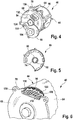
- FIG. 4 a further embodiment of an electrical machine arrangement is shown.
- the machine housing flange 78 may have a plurality of radially projecting eyes on which respective holes 130 are formed for the passage of screws or the like.
- an electrical plug connector via which the stator windings can be electrically contacted, is formed on the second wall section 68.
- Fig. 5 shows the electrical machine assembly 40 of Fig. 4 from the back, it being understood that the first wall section 66 shown here indeed has a ring land 74, but otherwise may be provided with openings and recesses in order to save weight.
- Fig. 6 shows a similar view as Fig. 4 but shows a detail in which the machine housing 44 is broken away.
- the stator 56 has a laminated core 120 with a plurality of axial cooling channels 122 which are formed between the cylinder section 64 and the laminated core 120.
- the distributor device 116 can be designed as an annular channel which is connected to the second wall section 68 and can be guided via the fluid toward the adjacent winding head 118.
Abstract
Elektrische Maschinenanordnung (40) für einen Kraftfahrzeugantriebsstrang (10), mit einem Maschinengehäuse (44), das an einem Antriebsstranggehäuse (26) festlegbar ist, einem Stator (46), der in Bezug auf das Maschinengehäuse (44) festgelegt ist, einem Rotor (50), der konzentrisch zu dem Stator (46) innerhalb des Maschinengehäuses (44) gelagert ist und eine Rotorachse (48) aufweist, wobei zwischen dem Stator (46) und dem Rotor (50) ein Luftspalt (60) definiert ist. Dabei weist das Maschinengehäuse einen zweiten Lagersitz (108) für eine Nebenwelle (104) auf, die parallel versetzt zu einer Längsachse des Rotors (50) ist.An electric machine assembly (40) for an automotive powertrain (10), comprising a machine housing (44) attachable to a driveline housing (26), a stator (46) fixed relative to the engine housing (44), a rotor ( 50) which is mounted concentrically with the stator (46) within the machine housing (44) and a rotor axis (48), wherein between the stator (46) and the rotor (50) an air gap (60) is defined. In this case, the machine housing has a second bearing seat (108) for a secondary shaft (104), which is parallel offset to a longitudinal axis of the rotor (50).
Description
Die vorliegende Erfindung betrifft eine elektrische Maschinenanordnung für einen Kraftfahrzeugantriebsstrang, mit einem Maschinengehäuse, das an einem Antriebsstranggehäuse festlegbar ist, mit einem Stator, der in Bezug auf das Maschinengehäuse festgelegt ist, mit einem Rotor, der konzentrisch zu dem Stator innerhalb des Maschinengehäuses gelagert ist und eine Rotorachse aufweist, wobei zwischen dem Stator und dem Rotor ein Luftspalt definiert ist.The present invention relates to an electrical machine assembly for a motor vehicle powertrain, comprising a machine housing attachable to a power train housing, having a stator fixed with respect to the machine housing, having a rotor mounted concentrically with the stator within the machine housing, and a rotor axis, wherein between the stator and the rotor, an air gap is defined.
Ferner betrifft die vorliegende Erfindung ein Kraftfahrzeuggetriebe mit einem Getriebegehäuse, innerhalb dessen eine elektrische Maschinenanordnung festgelegt ist.Furthermore, the present invention relates to a motor vehicle transmission with a transmission housing, within which an electrical machine assembly is set.
Schließlich betrifft die vorliegende Erfindung ein Verfahren zum Herstellen einer solchen elektrischen Maschinenanordnung.Finally, the present invention relates to a method for producing such an electrical machine arrangement.
Elektrische Maschinen eignen sich als Antriebsmaschinen für Kraftfahrzeuge, beispielsweise bei reinen Elektrofahrzeugen oder auch bei Kraftfahrzeugen mit Hybrid-Antriebsstrang. Bei Kraftfahrzeugen mit Hybrid-Antriebsstrang ist ein Verbrennungsmotor als Antriebsmotor vorgesehen, der in an sich üblicher Weise über ein Getriebe mit wenigstens einer angetriebenen Achse verbunden ist. Das Layout innerhalb des Kraftfahrzeuges ist dabei weitgehend vorgegeben. Für die Integration der elektrischen Maschinen in einen solchen Antriebsstrang gibt es eine Vielzahl von Möglichkeiten. Bei Antriebssträngen, bei denen die elektrische Maschine beispielsweise mit einem Eingang des Getriebes verbunden ist, kann die elektrische Maschine koaxial zu der Kurbelwelle des Verbrennungsmotors angeordnet sein. Ferner ist es bekannt, eine elektrische Maschine koaxial zu einer Abtriebswelle eines Getriebes anzuordnen. Auch ist es bekannt, eine elektrische Maschine außerhalb eines Getriebegehäuses anzuordnen und über geeignete Verbindungsmittel mit dem Getriebe zu verbinden, beispielsweise über ein Zugmittel oder einen Stirnradsatz.Electrical machines are suitable as drive machines for motor vehicles, for example in pure electric vehicles or even in motor vehicles with hybrid powertrain. In motor vehicles with hybrid powertrain, an internal combustion engine is provided as a drive motor, which is connected in a conventional manner via a transmission with at least one driven axle. The layout within the motor vehicle is largely predetermined. For the integration of electrical machines in such a drive train, there are a variety of ways. In drive trains in which the electric machine is connected, for example, to an input of the transmission, the electric machine can be arranged coaxially with the crankshaft of the internal combustion engine. Furthermore, it is known to arrange an electric machine coaxially with an output shaft of a transmission. It is also known to arrange an electrical machine outside of a transmission housing and to connect via suitable connecting means with the transmission, for example via a traction means or a spur gear.
Sofern die elektrische Maschine außerhalb des Getriebegehäuses angeordnet ist, weist die elektrische Maschine ein eigenes Maschinengehäuse auf, innerhalb dessen ein Rotor drehbar gelagert ist, in der Regel über zwei Drehlager wie Wälzlager.If the electric machine is arranged outside the gear housing, the electric machine has its own machine housing, within which a rotor is rotatably mounted, as a rule via two pivot bearings such as roller bearings.
Lagerkräfte werden bei dieser Anordnung über das Maschinengehäuse auf eine Aufhängung des Maschinengehäuses übertragen. Das Maschinengehäuse muss bei dieser Ausführungsform vergleichsweise stabil ausgelegt werden.Bearing forces are transmitted in this arrangement on the machine housing on a suspension of the machine housing. The machine housing must be designed comparatively stable in this embodiment.
Alternativ ist es auch bekannt, in einem Hybrid-Antriebsstrang die elektrische Maschine innerhalb des Getriebegehäuses aufzunehmen. Bei dieser Ausführungsform weist die elektrische Maschine kein "eigenes" Maschinengehäuse auf, vielmehr ist ein Abschnitt des Getriebegehäuses so ausgebildet, dass er ein Maschinengehäuse nachbildet. In diesem Fall wird ein Rotor beispielsweise drehbar in Bezug auf das Getriebegehäuse gelagert. Lagerkräfte können insofern direkt in das Getriebegehäuse eingeleitet werden, das ohnehin relativ stabil ausgeführt werden muss.Alternatively, it is also known to accommodate the electric machine within the transmission housing in a hybrid drive train. In this embodiment, the electric machine has no "own" machine housing, but a portion of the gear housing is formed so that it simulates a machine housing. In this case, for example, a rotor becomes rotatable with respect to the transmission case stored. In this respect, bearing forces can be introduced directly into the transmission housing, which in any case must be made relatively stable.
Ein gewisser Nachteil bei dieser Ausführungsform besteht darin, dass erst durch den Einbau des Stators und des Rotors in das Getriebe die ordnungsgemäße Funktion der elektrischen Maschinenanordnung überprüft werden kann. Eine späte Überprüfung der Funktionsfähigkeit der elektrischen Maschine bei der Herstellung des Hybrid-Antriebsstranges ist nachteilig, da bei Auftreten von Fehlern gegebenenfalls das gesamte Getriebe demontiert werden muss.A certain disadvantage of this embodiment is that only through the installation of the stator and the rotor in the transmission, the proper operation of the electrical machine assembly can be checked. A late check of the functionality of the electric machine in the production of the hybrid drive train is disadvantageous, since if errors occur, the entire transmission may need to be dismantled.
Bei der Anbindung einer elektrischen Maschinenanordnung mit eigenem Maschinengehäuse, das außerhalb des Getriebegehäuses angeordnet ist, stellt sich häufig das Problem der geeigneten Abdichtung bei der Anbindung einer Motorantriebswelle an ein Getriebeelement. Sofern eine komplett vormontierte elektrische Maschine mit eigenen Rotorlagern in das Getriebegehäuse einzubauen ist, ergeben sich Nachteile hinsichtlich Gewicht und Kosten. Denn in diesem Fall ist eine Vielzahl von Lagern vorzusehen. Das Maschinengehäuse muss stabil und folglich mit hohem Gewicht ausgebildet werden, obgleich die Lagerkräfte unmittelbar an das Getriebegehäuse übergeben werden, das ohnehin mechanisch stabil ausgeführt ist.In the connection of an electrical machine assembly with its own machine housing, which is arranged outside of the transmission housing, often poses the problem of suitable sealing in the connection of a motor drive shaft to a transmission element. If a completely pre-assembled electric machine with its own rotor bearings is to be installed in the gearbox housing, there are disadvantages in terms of weight and costs. Because in this case, a large number of bearings should be provided. The machine housing must be stable and therefore formed with high weight, although the bearing forces are transferred directly to the gear housing, which is already executed mechanically stable.
Ein Beispiel einer elektrischen Maschine, die ohne eigenes Maschinengehäuse in ein Getriebegehäuse eingebaut ist, ist aus dem Dokument
Weiterhin ist es aus dem Dokument
Aus dem Dokument
Schließlich offenbart das Dokument
Vor diesem Hintergrund ist es eine Aufgabe der Erfindung, eine verbesserte elektrische Maschinenanordnung, ein verbessertes Kraftfahrzeuggetriebe sowie ein verbessertes Verfahren zum Herstellen einer elektrischen Maschinenanordnung anzugeben, wobei vorzugsweise eine elektrische Maschine vor der Montage in einem Getriebegehäuse hinsichtlich der elektrischen Funktionen prüfbar ist und/oder wobei die elektrische Maschinenanordnung vorzugsweise kostengünstig und/oder mit geringem Gewicht ausgeführt werden kann.Against this background, it is an object of the invention to provide an improved electrical machine assembly, an improved motor vehicle transmission and an improved method for producing an electrical machine assembly, wherein preferably an electric machine before assembly in a transmission housing with respect to the electrical functions is testable and / or the electrical machine assembly can be preferably carried out inexpensively and / or with low weight.
Die obige Aufgabe wird gelöst durch eine elektrische Maschinenanordnung gemäß Anspruch 1, durch einen Kraftfahrzeugantriebsstrang gemäß Anspruch 13 sowie durch ein Verfahren zum Herstellen einer elektrischen Maschinenanordnung gemäß Anspruch 15.The above object is achieved by an electrical machine arrangement according to claim 1, by a motor vehicle drive train according to claim 13 and by a method for manufacturing an electrical machine arrangement according to claim 15.
Erfindungsgemäß weist das Maschinengehäuse einen zweiten Lagersitz für eine Nebenwelle auf, die parallel versetzt zu einer Längsachse des Rotors ist.According to the invention, the machine housing has a second bearing seat for a secondary shaft, which is offset parallel to a longitudinal axis of the rotor.
Die Verbindung zwischen der elektrischen Maschinenanordnung und dem Getriebe erfolgt vorzugsweise über eine Stirnradanordnung. Die Stirnradanordnung beinhaltet dabei vorzugsweise ein Antriebsritzel, das koaxial zu dem Rotor an einem Abschnitt des Rotors in Form der Maschinenantriebswelle festgelegt ist, sowie ein Zahnrad des Getriebes, beispielsweise ein Losrad, das einer Gangstufe des Getriebes zugeordnet ist. Von besonderem Vorzug ist es, wenn zwischen dem Zahnrad des Getriebes und dem Maschinenantriebsritzel ein weiteres Zahnrad vorgesehen ist, das vorzugsweise an einer Nebenwelle festgelegt ist. Die Nebenwelle ist in diesem Fall vorzugsweise zum einen drehbar über das Maschinengehäuse gelagert und zum anderen vorzugsweise über das Getriebegehäuse.The connection between the electrical machine assembly and the transmission is preferably via a spur gear. The spur gear assembly preferably includes a drive pinion, which is fixed coaxially to the rotor at a portion of the rotor in the form of the machine drive shaft, and a gear of the transmission, such as a loose wheel, which is associated with a gear stage of the transmission. It is particularly advantageous if between the gear of the transmission and the machine drive pinion another gear is provided, which is preferably fixed to a secondary shaft. The secondary shaft is in this case preferably rotatably supported by the machine housing and the other preferably via the transmission housing.
Mit anderen Worten wird das Maschinengehäuse von vorneherein so vorgesehen, dass eine Nebenwelle, an der ein solches Zwischenrad festgelegt ist, sich an einem axialen Ende an dem Maschinengehäuse lagern lässt.In other words, the machine housing is provided from the outset so that a secondary shaft, on which such an intermediate wheel is fixed, can be stored at one axial end on the machine housing.
Demzufolge ist es von Vorteil, wenn der zweite Lagersitz an einem zweiten Wandabschnitt des Maschinengehäuses ausgebildet ist, wobei an dem zweiten Wandabschnitt auch der Gehäuselagerabschnitt ausgebildet ist.Accordingly, it is advantageous if the second bearing seat is formed on a second wall portion of the machine housing, wherein on the second wall portion and the housing bearing portion is formed.
Der zweite Wandabschnitt ist vorzugsweise als Lagerplatte ausgebildet, mittels der sich die elektrische Maschine in dem Getriebegehäuse festlegen lässt. Der zweite Wandabschnitt kann dabei einen umfänglichen Flanschabschnitt aufweisen, mittels dessen eine derartige Festlegung beispielsweise über Schrauben realisierbar ist.The second wall section is preferably designed as a bearing plate, by means of which the electric machine can be fixed in the gear housing. The second wall portion may have a peripheral flange portion, by means of which such a definition can be realized for example by screws.
Der zweite Lagersitz an dem zweiten Wandabschnitt des Maschinengehäuses ist dabei vorzugsweise von außerhalb des Maschinengehäuses zugänglich. Das Drehlager, das vorzugsweise in dem zweiten Lagersitz eingesetzt wird, ist vorzugsweise ein Wälzlager.The second bearing seat on the second wall section of the machine housing is preferably accessible from outside the machine housing. The pivot bearing, which is preferably used in the second bearing seat, is preferably a rolling bearing.
Gemäß einer weiteren bevorzugten Ausführungsform ist ein erstes Zahnrad an einem zweiten Rotorendabschnitt gelagert, wobei an der Nebenwelle ein zweites Zahnrad gelagert ist, das mit dem ersten Zahnrad in Eingriff steht.According to a further preferred embodiment, a first gear is mounted on a second rotor end portion, wherein on the secondary shaft, a second gear is mounted, which is in engagement with the first gear.
Bei dieser Ausführungsform ist es möglich, die Nebenwelle mit dem zweiten Zahnrad an dem Maschinengehäuse vorzumontieren, derart, dass das zweite Zahnrad unmittelbar mit dem ersten Zahnrad in Eingriff steht.In this embodiment, it is possible to pre-assemble the secondary shaft with the second gear on the machine housing, such that the second gear is directly engaged with the first gear.
Der zweite Rotorendabschnitt ist dabei vorzugsweise jener Abschnitt des Rotors, der sich aus dem Maschinengehäuse heraus erstreckt. Das zweite Zahnrad ist vorzugsweise ein Zwischenzahnrad der oben beschriebenen Art.The second rotor end section is preferably that section of the rotor which extends out of the machine housing. The second gear is preferably an intermediate gear of the type described above.
Gemäß einer weiteren bevorzugten Ausführungsform, die in Verbindung mit den Merkmalen des Oberbegriffs des Anspruchs 1 eine eigene Erfindung darstellt, weist der Rotor einen ersten axialen Rotorendabschnitt auf, der über ein erstes Drehlager drehbar in Bezug auf das Maschinengehäuse gelagert ist, wobei das erste Drehlager an einem ersten Lagersitz eines ersten Wandabschnittes des Maschinengehäuses festgelegt ist und wobei der erste Wandabschnitt des Maschinengehäuses ferner so ausgebildet ist, dass von dem Rotor über das erste Drehlager in den ersten Wandabschnitt eingeleitete Radialkräfte in das Antriebsstranggehäuse übertragen werden können, wenn das Maschinengehäuse an dem Antriebsstranggehäuse festgelegt ist.According to a further preferred embodiment, which represents a separate invention in conjunction with the features of the preamble of claim 1, the rotor has a first axial rotor end portion which is rotatably supported via a first pivot bearing with respect to the machine housing, wherein the first pivot bearing a first bearing seat of a first wall portion of the machine housing is set and wherein the first wall portion of the machine housing is further configured so that from the rotor via the first pivot bearing in the first wall portion introduced radial forces can be transmitted to the drive train housing when the machine housing fixed to the drive train housing is.
Bei dem erfindungsgemäßen Kraftfahrzeuggetriebe werden folglich Lagerkräfte, die über das erste Drehlager in den ersten Wandabschnitt eingeleitet werden, unmittelbar in das Getriebegehäuse eingeleitet.In the motor vehicle transmission according to the invention, therefore, bearing forces which are introduced into the first wall section via the first rotary bearing are introduced directly into the transmission housing.
Der erste Wandabschnitt des Maschinengehäuses kann daher so ausgebildet werden, dass er keine hohen radialen Kräfte übertragen muss. Folglich kann das Maschinengehäuse insgesamt mit geringem Gewicht realisiert werden.The first wall section of the machine housing can therefore be designed so that it does not have to transmit high radial forces. Consequently, the machine housing can be realized with a light weight overall.
Von besonderem Vorzug ist es, wenn das Maschinengehäuse hierbei einen zweiten Wandabschnitt aufweist, an dem der Gehäuselagerabschnitt ausgebildet ist, wobei der zweite Wandabschnitt beispielsweise als stabile Lagerplatte ausgebildet sein kann. Ein Zylinderabschnitt des Maschinengehäuses zwischen den Wandabschnitten und der erste Wandabschnitt können vorzugsweise einstückig ausgebildet sein. Da der Zylinderabschnitt und der erste Wandabschnitt keine hohen Kräfte übertragen müssen, kann dieser Teil des Maschinengehäuses beispielsweise aus einem dünnen Material wie einem Blech hergestellt sein.It is of particular advantage if the machine housing in this case has a second wall portion on which the housing bearing portion is formed, wherein the second wall portion may be formed, for example, as a stable bearing plate. A cylinder portion of the machine housing between the wall portions and the first wall portion may preferably be integrally formed. Since the cylinder section and the first wall section do not have to transmit high forces, For example, this part of the machine housing may be made of a thin material such as a sheet metal.
Von besonderem Vorzug ist es hierbei, wenn der erste Wandabschnitt einen Ringsteg aufweist, der in eine Ringstegaufnahme des Antriebsstranggehäuses einsetzbar ist.It is of particular advantage in this case if the first wall section has an annular web which can be inserted into an annular web receptacle of the drive train housing.
Der Ringsteg und die Ringstegaufnahme sind dabei vorzugsweise koaxial zu dem ersten Lagersitz ausgebildet.The ring land and the ring land receiving are preferably formed coaxially with the first bearing seat.
Der Ringsteg ist vorzugsweise in axialer Richtung überlappend oder benachbart zu dem ersten Lagersitz des ersten Wandabschnittes des Maschinengehäuses angeordnet.The annular web is preferably arranged in the axial direction overlapping or adjacent to the first bearing seat of the first wall portion of the machine housing.
Folglich können auf diese Weise Radialkräfte über den Ringsteg im Wesentlichen direkt in radialer Richtung in das Antriebsstranggehäuse geleitet werden.Consequently, in this way radial forces can be conducted via the annular web substantially directly in the radial direction into the drive train housing.
In einer bevorzugten Ausführungsform ist vorgesehen, dass der Rotor einen Rotorlagerabschnitt aufweist, der mit radialem Spiel drehbar in Bezug auf einen Gehäuselagerabschnitt des Maschinengehäuses gelagert ist, wobei das radiale Spiel kleiner ist als der Luftspalt zwischen Rotor und Stator.In a preferred embodiment it is provided that the rotor has a rotor bearing portion which is rotatably supported with radial play with respect to a housing bearing portion of the machine housing, wherein the radial clearance is smaller than the air gap between the rotor and stator.
Bei der bevorzugten Ausführungsform der elektrischen Maschinenanordnung ist es möglich, diese vor Montage an einem Kraftfahrzeug-Antriebsstrang auf ihre Funktionsfähigkeit hin zu testen, insbesondere in elektrischer Hinsicht. Durch die Maßnahme, einen Rotorlagerabschnitt direkt in einem Gehäuselagerabschnitt des Maschinengehäuses in radialer Richtung verdrehbar zu lagern, ist es dabei auf einfache Weise möglich, den Rotor beispielsweise in einer Testumgebung an eine Last anzuschließen. Die Testumgebung ist vorzugsweise so ausgebildet, dass für den Rotor geeignete Maschinenlager bereitgestellt sind. Sofern die elektrische Maschinenanordnung noch nicht in Betrieb ist, wird vermieden, dass der Rotor den Stator kontaktiert. Dies könnte insbesondere möglich sein, wenn der Rotor magnetisiert ist, insbesondere, wenn an dem Rotor Permanentmagnete festgelegt sind. Durch die Anziehungskräfte könnten Rotor und/oder Stator beschädigt werden, wenn diese einander berühren. Das Lösen ist zudem in diesem Fall sehr aufwändig und erfordert hohe Kräfte. Durch die Maßnahme, das radiale Spiel kleiner zu wählen als die Abmessung des Luftspaltes, kann ein solcher Kontakt zwischen Rotor und Stator sicher ausgeschlossen werden. Dies gilt insbesondere für eine Phase, nachdem eine elektrische Maschinenanordnung auf ihre Funktionsfähigkeit hin getestet worden ist und bis zu dem Zeitpunkt, bei dem sie an einem Antriebsstrang festgelegt wird.In the preferred embodiment of the electrical machine assembly, it is possible to test these before assembly on a motor vehicle powertrain for their functionality, in particular in electrical terms. By the measure, to store a rotor bearing portion directly rotatable in a housing bearing portion of the machine housing in the radial direction, it is possible in a simple manner to connect the rotor, for example in a test environment to a load. The test environment is preferably designed such that suitable machine bearings are provided for the rotor. If the electrical machine arrangement is not yet in operation, it is avoided that the rotor contacts the stator. This could be possible in particular if the rotor is magnetized, in particular if on the rotor Permanent magnets are fixed. The forces of attraction could damage the rotor and / or stator when they touch each other. The release is also very complicated in this case and requires high forces. By the measure, the radial clearance to choose smaller than the dimension of the air gap, such a contact between the rotor and stator can be safely excluded. This is particularly true for a phase after an electrical machine assembly has been tested for operability and until it is committed to a powertrain.
Die Radiallagerung des Rotorlagerabschnittes an dem Gehäuselagerabschnitt stellt also eine Art "Transportsicherung" dar, die den Rotor innerhalb enger Grenzen in Bezug auf das Maschinengehäuse und in Bezug auf den Stator führt.The radial bearing of the rotor bearing portion on the housing bearing portion thus represents a kind of "transport safety", which guides the rotor within narrow limits with respect to the machine housing and with respect to the stator.
Der Rotor kann dabei einen Rotorlagerabschnitt aufweisen, der beispielsweise im Bereich von einem axialen Rotorendabschnitt ausgebildet ist. In diesem Fall kann an dem anderen axialen Endabschnitt eine Lagerung des Rotors an dem Maschinengehäuse über ein Drehlager erfolgen, wie beispielsweise ein Wälzlager.The rotor can have a rotor bearing section which is formed, for example, in the region of an axial rotor end section. In this case, at the other axial end portion, a bearing of the rotor on the machine housing via a rotary bearing, such as a rolling bearing.
Alternativ ist es möglich, dass der Rotor im Bereich von zwei gegenüberliegenden axialen Rotorendabschnitten jeweils einen Rotorlagerabschnitt aufweist, wobei in diesem Fall das Maschinengehäuse in entsprechender Weise zwei zugeordnete Gehäuselagerabschnitte aufweisen könnte.Alternatively, it is possible for the rotor to each have a rotor bearing section in the region of two opposite axial rotor end sections, in which case the machine housing could correspondingly have two associated housing bearing sections.
Das Maschinengehäuse ist vorzugsweise so aufgebaut, dass es innerhalb des Antriebsstranggehäuses festlegbar ist, insbesondere im Innenraum eines Getriebegehäuses. Der Stator ist vorzugsweise innerhalb des Maschinengehäuses festgelegt. Der Rotor ist drehbar innerhalb des Maschinengehäuses gelagert, ist jedoch vorzugsweise hinsichtlich seiner axialen Lage in Bezug auf das Maschinengehäuse fixiert, so dass bei der elektrischen Maschinenanordnung Relativbewegungen zwischen dem Stator und dem Rotor in axialer Richtung ausgeschlossen werden können.The machine housing is preferably constructed so that it can be fixed within the drive train housing, in particular in the interior of a transmission housing. The stator is preferably fixed within the machine housing. The rotor is rotatably supported within the machine housing, but is preferably fixed with respect to its axial position with respect to the machine housing, so that in the electrical machine assembly relative movements between the stator and the rotor in the axial direction can be excluded.
Vorzugsweise erfolgt demgemäß bei einer Montage der Maschinenanordnung an einem Antriebsstrang auch kein axialer Relativversatz zwischen Stator und Rotor.Accordingly, in an assembly of the machine arrangement on a drive train, no axial relative offset between stator and rotor preferably takes place.
Der Luftspalt zwischen Stator und Rotor ist ein Nennmaß, das insbesondere für den Betrieb der elektrischen Maschinenanordnung festgelegt ist (innerhalb sehr enger Toleranzen). Das radiale Spiel zwischen Rotorlagerabschnitt und Gehäuselagerabschnitt ist kleiner als der Luftspalt. In dem vormontierten Zustand vor Einbau an einem Antriebsstrang kann der Luftspalt folglich noch um das radiale Spiel variabel sein.The air gap between stator and rotor is a nominal size, which is determined in particular for the operation of the electrical machine assembly (within very narrow tolerances). The radial clearance between the rotor bearing portion and the housing bearing portion is smaller than the air gap. In the preassembled state before installation on a drive train, the air gap can consequently still be variable by the radial clearance.
Vorzugsweise ist der Rotor über die Lagerung am Maschinengehäuse nicht drehfixiert, ist also in Umfangsrichtung frei in Bezug auf den Gehäuselagerabschnitt verdrehbar.Preferably, the rotor is not rotationally fixed via the bearing on the machine housing, so it is freely rotatable in the circumferential direction with respect to the housing bearing portion.
Der Gehäuselagerabschnitt und der Rotorlagerabschnitt bilden eine Art Zentrierungseinrichtung. Die Abmessung des Luftspaltes ist in radialer Richtung wenigstens zweimal so groß wie das radiale Spiel, insbesondere fünfmal so groß, und vorzugsweise wenigstens zehnmal so groß, ist jedoch vorzugsweise kleiner als das 100-fache des Radialspiels.The housing bearing portion and the rotor bearing portion form a kind of centering device. The dimension of the air gap is in the radial direction at least twice as large as the radial clearance, in particular five times as large, and preferably at least ten times as large, but is preferably less than 100 times the radial clearance.
Insgesamt kann bei dem erfindungsgemäßen Kraftfahrzeuggetriebe ferner vorgesehen sein, dass der Rotor im Bereich von wenigstens einem axialen Rotorendabschnitt drehbar in Bezug auf das Getriebegehäuse gelagert wird, insbesondere über ein Drehlager wie ein Wälzlager. Dies kann insbesondere jener Abschnitt sein, an dessen axialem Ende auch der Rotorlagerabschnitt ausgebildet ist.Overall, it can further be provided in the motor vehicle transmission according to the invention that the rotor is rotatably mounted in the region of at least one axial rotor end portion with respect to the transmission housing, in particular via a rotary bearing such as a rolling bearing. This may in particular be that section at whose axial end the rotor bearing section is also formed.
Insgesamt kann das Gesamtsystem aus elektrischer Maschinenanordnung und Kraftfahrzeuggetriebe auf niedriges Gesamtgewicht optimiert sein. Ferner kann das erfindungsgemäße Kraftfahrzeuggetriebe leichter montiert werden. Denn bei der Montage der elektrischen Maschinenanordnung müssen keine besonderen Maßnahmen dafür getroffen werden, dass der Rotor in Bezug auf den Stator zentriert wird. Eine derartige Zentrierung kann bereits über die Lagerung des Rotorlagerabschnittes an dem Gehäuselagerabschnitt des Maschinengehäuses realisiert werden. Die Montage kann daher mit relativ einfachen Mitteln erfolgen. Rotor und Stator können folglich auch gemeinsam innerhalb des Maschinengehäuses zur Getriebemontage transportiert werden.Overall, the overall system of electrical machine assembly and motor vehicle transmission can be optimized for low total weight. Furthermore, the motor vehicle transmission according to the invention can be mounted more easily. Because during assembly of the electrical machine assembly no special measures must be taken to ensure that the rotor is centered with respect to the stator. Such centering can already on the storage of the rotor bearing portion of the Housing bearing section of the machine housing can be realized. The assembly can therefore be done with relatively simple means. Consequently, rotor and stator can also be transported together within the machine housing for gearbox assembly.
Im Gegensatz zu elektrischen Maschinenanordnungen, die über zwei eigene Rotorwellenlager verfügen, ist es in der Regel dennoch notwendig, auch eine Lagerung eines Abschnittes der Maschinenantriebswelle bzw. des Rotors in Bezug auf das Getriebegehäuse vorzusehen, insbesondere zum Abstützen von Axialkräften bzw. Querkräften aus einer (Schräg-)Verzahnung eines Ritzels, das mit der Maschinenantriebswelle verbunden ist. Demzufolge sind in diesem Fall häufig drei Wälzlager vorzusehen, was zu hohen Kosten, hohem Gewicht und letztendlich erhöhten Schleppverlusten (geringerer Wirkungsgrad) führt.In contrast to electrical machine arrangements, which have their own two rotor shaft bearings, it is generally still necessary to provide a bearing of a portion of the machine drive shaft or of the rotor with respect to the gear housing, in particular for supporting axial forces or transverse forces from a ( Helical) teeth of a pinion connected to the machine drive shaft. Accordingly, in this case, three rolling bearings are often to be provided, resulting in high cost, high weight and ultimately increased drag losses (lower efficiency).
Bei der elektrischen Maschinenanordnung und dem Kraftfahrzeuggetriebe ist eine Lagerung des Rotors über nur zwei Drehlager, beispielsweise in Form von Wälzlagern, möglich, so dass diese Nachteile gegebenenfalls vermieden werden können.In the electrical machine arrangement and the motor vehicle transmission, a bearing of the rotor via only two pivot bearings, for example in the form of rolling bearings, is possible, so that these disadvantages can optionally be avoided.
Gemäß einer weiteren bevorzugten Ausführungsform, die in Verbindung mit den Merkmalen des Oberbegriffs des Anspruchs 1 eine eigene Erfindung darstellt, weist der Rotor einen ersten axialen Rotorendabschnitt auf, der über ein erstes Drehlager wie ein Wälzlager drehbar in Bezug auf das Maschinengehäuse gelagert ist, wobei der Rotor einen zweiten axialen Rotorendabschnitt aufweist, der sich in einer axialen Richtung zumindest teilweise aus dem Maschinengehäuse heraus erstreckt und dazu ausgebildet ist, mittels eines zweiten Drehlagers wie eines Wälzlagers drehbar in Bezug auf das Antriebsstranggehäuse gelagert zu werden.According to a further preferred embodiment, which constitutes a separate invention in conjunction with the features of the preamble of claim 1, the rotor has a first axial rotor end portion which is rotatably supported via a first pivot bearing such as a rolling bearing with respect to the machine housing, wherein the Rotor having a second axial Rotorendabschnitt, which extends in an axial direction at least partially from the machine housing and is adapted to be rotatably supported by means of a second pivot bearing such as a rolling bearing with respect to the drive train housing.
Die vormontierte elektrische Maschinenanordnung sieht folglich vor, dass der Rotor vorzugsweise ausschließlich über ein erstes und ein zweites Drehlager gelagert wird, von denen eines sich an dem Maschinengehäuse abstützt und von denen sich das zweite an dem Antriebstranggehäuse abstützt.The pre-assembled electrical machine arrangement thus provides that the rotor is preferably mounted exclusively via a first and a second pivot bearing, one of which is supported on the machine housing and of which the second is supported on the drive train housing.
Insgesamt kann so eine elektrische Maschinenanordnung mit einer minimalen Anzahl an Lagern und der Möglichkeit bereitgestellt werden, im Bereich eines sich aus dem Maschinengehäuse heraus erstreckenden Abschnittes des Rotors ein Ritzel anzubringen, das schrägverzahnt ist. Denn die hierbei auftretenden Axialkräfte können dabei über das zweite Drehlager vorzugsweise aufgenommen werden.Overall, such an electrical machine assembly can be provided with a minimum number of bearings and the possibility to install a pinion in the region of a extending out of the machine housing portion of the rotor, which is helical. Because the axial forces occurring in this case can be preferably absorbed via the second pivot bearing.
Demzufolge ist es bevorzugt, wenn an dem zweiten axialen Rotorendabschnitt ein Zahnrad gelagert ist.Accordingly, it is preferable if a gear is supported on the second axial rotor end portion.
Das Zahnrad ist dabei insbesondere an dem zweiten axialen Rotorendabschnitt festgelegt, der hierbei eine Maschinenantriebswelle bildet. Das Zahnrad ist insbesondere ein Antriebsritzel der elektrischen Maschinenanordnung. Von besonderem Vorzug ist es, wenn das Zahnrad in axialer Richtung zwischen dem Maschinengehäuse und einem Abschnitt angeordnet ist, an dem das zweite Drehlager festgelegt wird.The gear is in particular fixed to the second axial Rotorendabschnitt, which in this case forms a machine drive shaft. The gear is in particular a drive pinion of the electrical machine arrangement. It is particularly advantageous when the gear is arranged in the axial direction between the machine housing and a portion at which the second pivot bearing is fixed.
Folglich ist es vorteilhaft, wenn das Zahnrad in der axialen Richtung zwischen dem Maschinengehäuse und einem Drehlagerbereich des zweiten Rotorendabschnittes angeordnet ist.Consequently, it is advantageous if the gear is arranged in the axial direction between the machine housing and a rotary bearing area of the second rotor end section.
Ferner ist es insgesamt vorteilhaft, wenn der Stator ein Blechpaket aufweist, das in einen Zylinderabschnitt des Maschinengehäuses eingesetzt ist, wobei zwischen dem Blechpaket und dem Zylinderabschnitt wenigstens ein Kühlkanal ausgebildet ist.Furthermore, it is altogether advantageous if the stator has a laminated core which is inserted into a cylinder section of the machine housing, wherein at least one cooling channel is formed between the laminated core and the cylinder section.
Der Kühlkanal ist vorzugsweise direkt gebildet durch das Blechpaket und den Zylinderabschnitt, so dass eine direkte Kühlung des Stators realisierbar ist. Das Kühlfluid, das durch den Kühlkanal hindurchleitbar ist, ist vorzugsweise ein Fluid aus dem Antriebsstrang, vorzugsweise Getriebeöl. Bei einer Abdichtung des Kühlkanals könnte jedoch auch ein spezielles Kühlfluid wie Wasser verwendet werden.The cooling channel is preferably formed directly by the laminated core and the cylinder portion, so that a direct cooling of the stator can be realized. The cooling fluid that can be passed through the cooling channel is preferably a fluid from the drive train, preferably transmission oil. However, if the cooling channel is sealed, a special cooling fluid, such as water, could be used.
Der Zylinderabschnitt des Maschinengehäuses kann, wie oben erwähnt, einstückig mit einem ersten Wandabschnitt ausgebildet sein.The cylinder portion of the machine housing may, as mentioned above, be formed integrally with a first wall portion.
Ferner ist es vorteilhaft, wenn zwischen dem Blechpaket und dem Zylinderabschnitt eine Mehrzahl von Kühlkanälen ausgebildet ist, die vorzugsweise über den Umfang verteilt sind, wobei eine Verteilereinrichtung zum Zuführen von Kühlfluid zu den Kühlkanälen im Bereich eines zweiten Wandabschnittes des Maschinengehäuses ausgebildet ist.Furthermore, it is advantageous if between the laminated core and the cylinder portion a plurality of cooling channels is formed, which are preferably distributed over the circumference, wherein a distributor device for supplying cooling fluid to the cooling channels in the region of a second wall portion of the machine housing is formed.
Die Verteilereinrichtung kann dabei von der Funktionsweise her ausgebildet sein, wie es in dem Dokument
Das Maschinengehäuse kann gegenüber dem Innenraum des Antriebsstranggehäuses wie dem Kraftfahrzeuggetriebegehäuse offen sein, wobei beispielsweise für Lager zum Drehlagern des Rotors das Fluid aus dem Getriebegehäuse verwendbar ist (Getriebeöl wie beispielsweise ATF-ÖI).The engine housing may be open to the interior of the drive train housing such as the motor vehicle transmission housing, for example, for bearings for pivot bearings of the rotor, the fluid from the transmission housing is used (transmission fluid such as ATF oil).
In weiteren Ausführungsformen ist es bevorzugt, wenn zumindest ein Teil des Maschinengehäuses gegenüber dem Innenraum des Antriebsstranggehäuses abgedichtet ist. Der abgedichtete Teil kann dabei beispielsweise ein Kühlbereich sein, mittels dessen die elektrische Maschine gekühlt wird, um auf diese Weise ein spezielles Kühlfluid verwenden zu können.In further embodiments, it is preferred if at least a part of the machine housing is sealed off from the interior of the drive train housing. The sealed part may be, for example, a cooling area, by means of which the electric machine is cooled in order to be able to use a special cooling fluid in this way.
Bei dem erfindungsgemäßen Verfahren ist es von besonderem Vorzug, wenn der andere Rotorendabschnitt über ein erstes Drehlager wie ein Wälzlager drehbar in Bezug auf das Maschinengehäuse gelagert wird und/oder der eine Rotorendabschnitt so in den Gehäuselagerabschnitt eingeführt wird, dass er sich teilweise aus dem Maschinengehäuse heraus erstreckt.In the method according to the invention, it is particularly advantageous if the other rotor end portion is rotatably supported via a first pivot bearing such as a rolling bearing with respect to the machine housing and / or the rotor end portion is inserted into the housing bearing portion so that it partially out of the machine housing extends.
Insgesamt kann die Rotorwelle für ihren Betrieb mittels zwei Wälzlagern, insbesondere Kugellagern gelagert sein. Eines der Lager ist dabei vorzugsweise Teil der elektrischen Maschinenanordnung, das andere Lager ist vorzugsweise nicht Teil der elektrischen Maschinenanordnung und wird erst beim Einbau in ein Getriebegehäuse montiert.Overall, the rotor shaft can be supported for their operation by means of two rolling bearings, in particular ball bearings. One of the bearings is preferably part of the electrical machine assembly, the other bearing is preferably not part of electrical machine assembly and is mounted only during installation in a transmission housing.
An dem Maschinengehäuse ist vorzugsweise eine axiale Übergabestelle zur Übergabe von Kühlfluid vorhanden, wobei die Übergabestelle vorzugsweise im Bereich des zweiten Wandabschnittes ausgebildet ist. Über die Übergabestelle kann Kühlfluid beispielsweise zu der Verteilereinrichtung zugeführt werden.An axial transfer point for transferring cooling fluid is preferably present on the machine housing, wherein the transfer point is preferably formed in the region of the second wall section. By way of the transfer point, cooling fluid can be supplied to the distributor device, for example.
Bei einer klein ausgeführten elektrischen Maschine und bei geringen radialen Lagerkräften kann eine Lagerung des Rotors auch direkt über das Maschinengehäuse erfolgen, so dass Lagerkräfte in das Maschinengehäuse eingeleitet werden und keine radiale Abstützung des Maschinengehäuses im Antriebsstranggehäuse notwendig ist. Die Zentrierung des Rotorlagerabschnittes an dem Gehäuselagerabschnitt kann an einem Wellenabschnitt des Rotors, am Ritzel, an Rotorpaket der elektrischen Maschine oder an einem anderen Bauteil der Rotorwelle erfolgen. In manchen Fällen beinhaltet die elektrische Maschinenanordnung gar kein Betriebs-Wellenlager, insbesondere, wenn eine solche Zentrierung auf beiden axialen Enden vorgesehen ist.In a small-scale electric machine and at low radial bearing forces a bearing of the rotor can also be done directly on the machine housing, so that bearing forces are introduced into the machine housing and no radial support of the machine housing in the drive train housing is necessary. The centering of the rotor bearing section on the housing bearing section can take place on a shaft section of the rotor, on the pinion, on the rotor core of the electric machine or on another component of the rotor shaft. In some cases, the electrical machine assembly does not include an operating shaft bearing, especially if such centering is provided on both axial ends.
Die elektrische Maschinenanordnung ist unmittelbar nach der Montage beim Hersteller prüfbar, wobei die elektrische Maschinenanordnung zu diesem Zweck vorzugsweise in einer Aufnahme montiert wird, die geometrisch dem Einbau im Getriebegehäuse entspricht. Nach der Prüfung kann die elektrische Maschinenanordnung transportiert werden, da durch die Zentriereinrichtung zwischen Rotorlagerabschnitt und Gehäuselagerabschnitt keine Gefahr besteht, dass der Rotor innen am Statorumfang anstößt. Zumindest der erste Wandabschnitt und der Zylinderabschnitt des Maschinengehäuses können aufgrund der Tatsache, dass nur geringe Lagerkräfte aufgenommen werden müssen, dünnwandig oder besonders leicht ausgeführt werden, und können gegebenenfalls auch mit großflächigen Ausnehmungen ausgebildet werden. Die Hauptfunktion insbesondere von dem Zylinderabschnitt und dem ersten Wandabschnitt ist dabei die Umhüllung des Statorpaketes der elektrischen Maschine einerseits und die Zentrierung der Welle darin, sowie der Abschluss von etwaigen Statorkühleinrichtungen, die vorzugsweise an der Außenseite des Stators ausgebildet sind.The electrical machine assembly can be tested immediately after assembly at the manufacturer, wherein the electrical machine assembly is preferably mounted for this purpose in a receptacle which corresponds geometrically to the installation in the transmission housing. After the test, the electrical machine assembly can be transported because there is no danger that the rotor abuts the inside of the stator circumference by the centering device between the rotor bearing portion and the housing bearing portion. At least the first wall section and the cylinder section of the machine housing can be made thin-walled or particularly light due to the fact that only small bearing forces have to be absorbed, and can optionally also be formed with large-area recesses. The main function in particular of the cylinder section and the first wall section is the enclosure of the stator of the electric machine on the one hand and the centering of the shaft therein, as well as the conclusion of any Statorkühleinrichtungen, which are preferably formed on the outside of the stator.
Es versteht sich, dass die vorstehend genannten und die nachstehend noch zu erläuternden Merkmale nicht nur in der jeweils angegebenen Kombination, sondern auch in anderen Kombinationen oder in Alleinstellung verwendbar sind, ohne den Rahmen der vorliegenden Erfindung zu verlassen.It is understood that the features mentioned above and those yet to be explained below can be used not only in the particular combination given, but also in other combinations or in isolation, without departing from the scope of the present invention.
Ausführungsbeispiele der Erfindung sind in der Zeichnung dargestellt und werden in der nachfolgenden Beschreibung näher erläutert. Es zeigen:
- Fig. 1
- eine schematische Darstellung eines Kraftfahrzeug-Antriebsstranges mit einem erfindungsgemäßen Kraftfahrzeuggetriebe und einer darin montierten erfindungsgemäßen elektrischen Maschinenanordnung;
- Fig. 2
- eine schematische Darstellung eines weiteren Antriebsstranges mit einer elektrischen Maschinenanordnung;
- Fig. 3
- eine weitere Darstellung eines Antriebsstranges mit einer elektrischen Maschinenanordnung in einer Teil-Längsschnittdarstellung;
- Fig. 4
- eine schematische perspektivische Außenansicht einer weiteren Ausführungsform einer elektrischen Maschinenanordnung;
- Fig. 5
- eine weitere perspektivische Ansicht der elektrischen Maschinenanordnung der
Fig. 4 ; und - Fig. 6
- eine schematische perspektivische, teilweise aufgebrochene Darstellung einer elektrischen Maschinenanordnung der erfindungsgemäßen Art.
- Fig. 1
- a schematic representation of a motor vehicle drive train with a motor vehicle transmission according to the invention and an electric machine assembly according to the invention mounted therein;
- Fig. 2
- a schematic representation of another drive train with an electrical machine assembly;
- Fig. 3
- a further illustration of a drive train with an electrical machine assembly in a partial longitudinal sectional view;
- Fig. 4
- a schematic perspective external view of another embodiment of an electrical machine assembly;
- Fig. 5
- another perspective view of the electrical machine assembly of
Fig. 4 ; and - Fig. 6
- a schematic perspective, partially broken view of an electrical machine assembly of the type according to the invention.
In
Der Antriebsstrang 10 weist einen primären Antriebsmotor 12 auf, beispielsweise in Form eines Verbrennungsmotors. Ferner beinhaltet der Antriebsstrang 10 eine Kupplungsanordnung 14, die eingangsseitig mit dem Antriebsmotor 12 verbunden ist, und ausgangsseitig mit einer Getriebeanordnung 16. Ein Ausgang der Getriebeanordnung 16 ist mit einem Differential 18 verbunden, mittels dessen Antriebsleistung auf angetriebene Räder 20L, 20R verteilbar ist.The
Die Getriebeanordnung 16 beinhaltet ein Stufengetriebe 24, das vorliegend als Vorgelegegetriebe in Stirnradbauweise ausgeführt ist. Das Getriebe 24 weist ein Getriebegehäuse 26 auf, an dem eine Eingangswellenanordnung 28 gelagert ist. Die Eingangswellenanordnung 28 ist mit der Kupplungsanordnung 14 verbunden.The
Ferner ist an dem Getriebegehäuse 26 eine Ausgangswellenanordnung 30 gelagert, die mit dem Differential 18 verbunden ist. Eine Mehrzahl von Gang-Radsätzen 32 (von denen in
Das Getriebe 24 kann als manuelles Getriebe ausgebildet sein, kann jedoch auch ein automatisiertes Getriebe sein. Insbesondere kann das Getriebe 24 ein Doppelkupplungsgetriebe sein. In diesem Fall beinhaltet die Kupplungsanordnung 14 zwei Reibkupplungen, und die Eingangswellenanordnung 28 beinhaltet zwei Eingangswellen, wie es im Stand der Technik an sich bekannt ist. Bei Doppelkupplungsgetrieben erfolgen Gangwechsel durch Überschneiden der Betätigung der Kupplungen der Kupplungsanordnung 14, so dass Gangwechsel im Wesentlichen ohne Zugkrafteinbruch durchgeführt werden können.The
Vorliegend beinhaltet der Antriebsstrang 10 eine elektrische Maschinenanordnung 40, wobei die elektrische Maschinenanordnung 40 als sekundärer Antriebsmotor betrieben werden kann, aber auch als Generator betrieben werden kann, um beispielsweise eine nicht näher dargestellte Batterie des Antriebsstranges 10 zu laden.In the present case, the
Die elektrische Maschinenanordnung 40 beinhaltet eine elektrische Maschine 42 und ein Maschinengehäuse 44. Die elektrische Maschine 42 weist einen Stator 46 auf, der in dem Maschinengehäuse 44 festgelegt ist. Die elektrische Maschine 42 und folglich deren Stator 46 sind koaxial zu einer Maschinen- oder Rotorachse 48 angeordnet. Die Maschinen- oder Rotorachse 48 ist parallel zu der Eingangswellenanordnung 28 und/oder der Ausgangswellenanordnung 30 ausgebildet.The
Die elektrische Maschine 42 weist ferner einen Rotor 50 auf, der vorliegend koaxial innerhalb des Stators 46 angeordnet ist und eine Antriebswelle 52 aufweist, die koaxial zu der Rotorachse 48 ausgerichtet ist. An der Antriebswelle 52 ist ein Antriebsritzel 54 festgelegt. Das Antriebsritzel 54 steht in Eingriff mit einem Zwischenrad 56. Das Zwischenrad 56 wiederum steht ebenfalls in Eingriff mit einem Losrad 58 eines Gang-Radsatzes 32 des Getriebes 24. Sofern die zugeordnete Schaltkupplung 34 geschlossen ist, kann folglich Antriebsleistung von der elektrischen Maschine 42 über den Stirnradsatz aus Antriebsritzel 54, Zwischenrad 56 und Losrad 58 auf den Ausgang des Getriebes 24 geführt werden.The
Die elektrische Maschine 42 kann dabei insbesondere mit einem von zwei Teilgetrieben des Getriebes 24 verbunden sein, wenn dieses als Doppelkupplungsgetriebe ausgebildet ist, insbesondere mit jenem Teilgetriebe, das den geraden Gangstufen und/oder einer Rückwärtsgangstufe zugeordnet ist.The
Die elektrische Maschine 42 kann über eine feste Übersetzungsstufe einer Eingangswelle des Getriebes 24, insbesondere der Eingangswelle von einem der Teilgetriebe des Getriebes 24, zugeordnet sein. Die feste Übersetzungsstufe kann durch geeignete Zahnräder gebildet sein, auch Losräder einer Gangverzahnung sind hierbei möglich. Ein Radsatz 32, an den die elektrische Maschine 42 angebunden sein kann, kann beispielsweise einer mittleren Gangstufe zugeordnet sein, wie beispielsweise der Gangstufe 4. Alternativ kann das Losrad 58 auch der Gangstufe 2 zugeordnet sein, oder auch der Gangstufe 6, oder einer noch höheren Gangstufe.The
Es ist jedoch auch denkbar, die elektrische Maschine 42 dem anderen Teilgetriebe zuzuordnen, in diesem Fall bevorzugt ebenfalls einer mittleren Gangstufe, beispielsweise der Gangstufe 3 oder der Gangstufe 5. Generell ist es auch denkbar, die elektrische Maschine 42 mit dem Ausgang des Getriebes 24 zu verbinden, die elektrische Maschine 42 folglich dem Abtrieb des Getriebes 24, d.h. drehzahlproportional zur Fahrgeschwindigkeit, zuzuordnen.However, it is also conceivable to associate the
In
Das Maschinengehäuse 44 beinhaltet einen Zylinderabschnitt 64, der koaxial zu der elektrischen Maschine 42 angeordnet ist und beispielsweise außen um den Stator 46 herum festgelegt ist. Das Maschinengehäuse 44 weist ferner einen ersten Wandabschnitt 66 auf, der auf der der Antriebswelle 52 axial gegenüberliegenden Seite der elektrischen Maschine 42 angeordnet ist, sowie einen zweiten Wandabschnitt 68, der der Antriebswelle 52 zugewandt ist.The
Der erste Wandabschnitt 66 und der Zylinderabschnitt 64 können einstückig miteinander ausgebildet sein, beispielsweise aus einem dünnen Material wie einem Blech. Der zweite Wandabschnitt 68 kann als Lagerplatte ausgebildet sein, die zur Aufnahme von Radialkräften und zur Übergabe solcher Radialkräfte an das Getriebegehäuse 26 ausgelegt ist. Der zweite Wandabschnitt 68 in Form einer solchen Lagerplatte kann zu diesem Zweck mit dem Getriebegehäuse 26 verbunden sein.The
Das Getriebegehäuse 26 weist eine erste Gehäusewand 70 auf, die etwa parallel zu dem ersten Wandabschnitt 66 des Maschinengehäuses 44 und benachbart hierzu angeordnet ist. Ferner beinhaltet das Getriebegehäuse 26 eine zweite Gehäusewand 72, die benachbart ist zu dem zweiten Wandabschnitt 68 des Maschinengehäuses 44.The
Der erste Wandabschnitt 66 des Maschinengehäuses 44 weist einen Ringsteg 74 auf, der koaxial zu der Rotorachse 48 ausgerichtet ist. Die erste Gehäusewand 70 weist eine Ringstegaufnahme 76 auf, in die der Ringsteg 74 axial eingeführt werden kann, derart, dass in den Ringsteg 74 eingeleitete radiale Kräfte auf das Getriebegehäuse 26 übertragen werden können.The
Das Maschinengehäuse 44 weist ferner im Bereich des zweiten Wandabschnittes 68 einen Maschinengehäuseflansch 78 auf, der über schematisch angedeutete Verbindungsmittel mit einem Getriebegehäuseflansch 80 des Getriebegehäuses 26 verbunden ist.The
Mit anderen Worten kann die elektrische Maschinenanordnung 40 in axialer Richtung in das Getriebegehäuse 26 eingeführt werden, bis der Ringsteg 74 in der Ringstegaufnahme 76 aufgenommen ist und der Maschinengehäuseflansch 78 an den Getriebegehäuseflansch 80 geschraubt oder sonst wie befestigt werden kann.In other words, the
Das Getriebegehäuse 26 kann ferner ergänzend eine Maschinengehäuseaufnahme 82 aufweisen, wie sie in
Der Rotor 50 weist einen ersten axialen Rotorendabschnitt 86 sowie einen gegenüberliegenden zweiten axialen Rotorendabschnitt 88 auf.The
Der erste axiale Rotorendabschnitt 86 ist über ein erstes Drehlager 90, das in einen ersten Lagersitz 92 des ersten Wandabschnittes 66 des Maschinengehäuses 44 eingesetzt ist, drehbar in Bezug auf das Maschinengehäuse 44 gelagert.The first
Der Lagersitz 92 ist vorzugsweise in axialer Überlappung mit dem Ringsteg 74 vorgesehen, um in das erste Drehlager 90 eingeleitete radiale Kräfte in das Getriebegehäuse einleiten zu können. Der Ringsteg 74 und der erste Lagersitz 92 können jedoch in axialer Richtung auch benachbart zueinander sein, so dass das Maschinengehäuse 44 radial eingeleitete Kräfte zunächst axial übertragen werden, um dann über den Ringsteg 74 in das Getriebegehäuse 26 geleitet zu werden.The bearing
Der zweite axiale Rotorendabschnitt 88 weist einen Rotorlagerabschnitt 98 auf, der mit einem radialen Spiel 99 drehbar in Bezug auf einen Gehäuselagerabschnitt 96 drehbar in Bezug auf das Maschinengehäuse 44 gelagert ist. Das Zusammenwirken zwischen Rotorlagerabschnitt 98 und Gehäuselagerabschnitt 96 dient der Zentrierung des Rotors 50 in diesem Bereich, also im Bereich des zweiten axialen Rotorendabschnittes 88. Das radiale Spiel 99 ist dabei deutlich kleiner als der radiale Luftspalt 60 zwischen Rotor 50 und Stator 46.The second axial
Hierdurch kann verhindert werden, dass in einem Transportzustand, wenn die Maschinenanordnung 40 noch nicht in das Getriebegehäuse 26 eingebaut ist, der Rotor 50 den Stator 46 kontaktiert, beispielsweise aufgrund der Tatsache, dass der Rotor 50 starke Permanentmagnete an seinem Außenumfang enthält.In this way, it can be prevented that, in a transportation state, when the
Der zweite axiale Rotorendabschnitt 88 ist ferner über ein zweites Drehlager 100 drehbar in Bezug auf die zweite Gehäusewand 72 des Getriebegehäuses 26 gelagert. Die Montage der zweiten Gehäusewand 72 und des Lagers 100 in Bezug auf den zweiten axialen Rotorendabschnitt 88 erfolgt vorzugsweise erst nachdem die elektrische Maschinenanordnung 40 in dem Getriebegehäuse 26 montiert worden ist.The second axial
Das Antriebsritzel 54 ist in axialer Richtung zwischen dem Rotorlagerabschnitt 98 und dem zweiten Drehlager 100 angeordnet. Das erste Drehlager 90 und das zweite Drehlager 100 können jeweils als Wälzlager, insbesondere als Kugellager ausgebildet sein.The
Sofern das Antriebsritzel 54 schrägverzahnt ist, dient das zweite Drehlager 100 vorzugsweise auch dazu, Axialkräfte aufzunehmen, die durch den Zahneingriff entstehen.If the
Das Zwischenrad 56 ist an einer Nebenwelle 104 festgelegt. Die Nebenwelle 104 ist über ein erstes Nebenwellenlager 106 drehbar in Bezug auf den zweiten Wandabschnitt 68 des Maschinengehäuses 44 gelagert. Zu diesem Zweck weist der zweite Wandabschnitt 68 einen zweiten Lagersitz 108 auf, der exzentrisch versetzt in Bezug auf die Rotorachse 48 an dem zweiten Wandabschnitt 68 ausgebildet ist.The intermediate 56 is fixed to a
Die Nebenwelle 104 wird auf der axial gegenüberliegenden Seite des Zwischenrades 56 mittels eines zweiten Nebenwellenlagers 110 drehbar in Bezug auf das Getriebegehäuse 26 gelagert, insbesondere in Bezug auf die zweite Gehäusewand 72. Zu diesem Zweck ist an der zweiten Gehäusewand 72 vorzugsweise ein geeigneter Lagersitz vorgesehen. Das erste Nebenwellenlager 106 und das zweite Nebenwellenlager 110 können jeweils als Wälzlager ausgebildet sein, insbesondere als Kugellager, können jedoch auch als Gleitlager ausgebildet sein.The
Die Nebenwelle 104 mit dem daran festgelegten Zwischenrad 56 kann mit der vormontierten elektrischen Maschinenanordnung 40 bereitgestellt werden, derart, dass in den zweiten Wandabschnitt 68 bereits das erste Nebenwellenlager 106 eingesetzt ist und die Nebenwelle 104 darin eingesetzt wird, derart, dass das Zwischenrad 56 mit dem Antriebsritzel 54 in Eingriff steht. Vorzugsweise erfolgt die Montage der Nebenwelle 104 mit ihren Lagern 106, 110 jedoch erst nachdem die elektrische Maschinenanordnung 40 an dem Getriebegehäuse 26 montiert worden ist.The
In den nachfolgenden Figuren sind weitere Ausführungsformen von Antriebssträngen und elektrischen Maschinenanordnungen dargestellt, die hinsichtlich Aufbau und Funktionsweise generell dem Antriebsstrang der
Es ist zu erkennen, dass das erste Drehlager 90 sich in axialer Richtung mit der Ringstegaufnahme 76 überlappt, um Radialkräfte über den Ringsteg 74 möglichst direkt in die erste Gehäusewand 70 des Getriebegehäuses 26 einleiten zu können.It can be seen that the first rotary bearing 90 overlaps in the axial direction with the
In
Der Stator 46 weist ferner ein Blechpaket 120 auf, das unmittelbar am Innenumfang des Zylinderabschnittes 64 anliegt. Dabei sind, über den Umfang verteilt, an dem Blechpaket 120 eine Mehrzahl von Kühlkanälen 122 ausgebildet, die sich in axialer Richtung erstrecken, derart, dass über den Fluidanschluss 114 eingeleitetes Fluid durch die Kühlkanäle 122 strömen kann, um den Stator 46 zu kühlen. Am axialen Ende, das dem ersten Wandabschnitt 66 benachbart ist, kann das Fluid aus den Kühlkanälen austreten und auf die dort vorgesehenen Wickelköpfe 118 geführt werden, um auch diese zu kühlen.The
Das Kühlkonzept kann dem Kühlkonzept entsprechen, das in den Dokumenten
Es ist zu erkennen, dass der zweite axiale Rotorendabschnitt 88, der sich aus dem zweiten Wandabschnitt 68 in axialer Richtung heraus erstreckt, als Hohlwelle ausgebildet ist und an seinem axialen Ende mit einer Abdeckkappe 124 verbunden ist, über die Kühlfluid, das über einen Axialkanal 126 in dem Rotorendabschnitt 66 zugeführt wird, hin zu dem zweiten Drehlager 100 führen zu können. Die Abdeckkappe 124 kann auch geschlossen sein, obgleich dies in
In den
Ferner ist zu erkennen, dass an dem zweiten Wandabschnitt 68 ein elektrischer Steckverbinder ausgebildet ist, über den die Statorwicklungen elektrisch kontaktiert werden können.Furthermore, it can be seen that an electrical plug connector, via which the stator windings can be electrically contacted, is formed on the
Ferner ist in
Claims (15)
das Maschinengehäuse (44) einen zweiten Lagersitz (108) für eine Nebenwelle (104) aufweist, die parallel versetzt zu einer Längsachse (48) des Rotors (50) ist.Electrical machine arrangement (40) for a motor vehicle drive train (10), with
the machine housing (44) has a second bearing seat (108) for a secondary shaft (104) which is parallel offset to a longitudinal axis (48) of the rotor (50).
Priority Applications (1)
| Application Number | Priority Date | Filing Date | Title |
|---|---|---|---|
| EP17157714.1A EP3206283A3 (en) | 2015-04-07 | 2015-04-07 | Electrical machine assembly, motor vehicle transmission gearboxes and method for producing an electrical machine assembly |
Applications Claiming Priority (2)
| Application Number | Priority Date | Filing Date | Title |
|---|---|---|---|
| EP17157714.1A EP3206283A3 (en) | 2015-04-07 | 2015-04-07 | Electrical machine assembly, motor vehicle transmission gearboxes and method for producing an electrical machine assembly |
| EP15162666.0A EP3079238B1 (en) | 2015-04-07 | 2015-04-07 | Electrical machine assembly and motor vehicle transmission gearbox |
Related Parent Applications (2)
| Application Number | Title | Priority Date | Filing Date |
|---|---|---|---|
| EP15162666.0A Division EP3079238B1 (en) | 2015-04-07 | 2015-04-07 | Electrical machine assembly and motor vehicle transmission gearbox |
| EP15162666.0A Division-Into EP3079238B1 (en) | 2015-04-07 | 2015-04-07 | Electrical machine assembly and motor vehicle transmission gearbox |
Publications (2)
| Publication Number | Publication Date |
|---|---|
| EP3206283A2 true EP3206283A2 (en) | 2017-08-16 |
| EP3206283A3 EP3206283A3 (en) | 2017-11-22 |
Family
ID=53002491
Family Applications (2)
| Application Number | Title | Priority Date | Filing Date |
|---|---|---|---|
| EP17157714.1A Withdrawn EP3206283A3 (en) | 2015-04-07 | 2015-04-07 | Electrical machine assembly, motor vehicle transmission gearboxes and method for producing an electrical machine assembly |
| EP15162666.0A Active EP3079238B1 (en) | 2015-04-07 | 2015-04-07 | Electrical machine assembly and motor vehicle transmission gearbox |
Family Applications After (1)
| Application Number | Title | Priority Date | Filing Date |
|---|---|---|---|
| EP15162666.0A Active EP3079238B1 (en) | 2015-04-07 | 2015-04-07 | Electrical machine assembly and motor vehicle transmission gearbox |
Country Status (3)
| Country | Link |
|---|---|
| US (1) | US10193415B2 (en) |
| EP (2) | EP3206283A3 (en) |
| CN (1) | CN106059171B (en) |
Families Citing this family (10)
| Publication number | Priority date | Publication date | Assignee | Title |
|---|---|---|---|---|
| DE102017206641A1 (en) * | 2017-04-20 | 2018-10-25 | Bayerische Motoren Werke Aktiengesellschaft | Drive unit and motor vehicle with a drive unit |
| DE102017213653A1 (en) * | 2017-08-07 | 2019-02-07 | Magna powertrain gmbh & co kg | driving device |
| DE102018001642A1 (en) | 2018-03-02 | 2019-09-05 | Daimler Ag | Drive unit for a motor vehicle, in particular for a motor vehicle |
| FR3080068B1 (en) * | 2018-04-17 | 2020-09-04 | Valeo Embrayages | DRIVE SYSTEM FOR A HYBRID MOTOR VEHICLE AND TRANSMISSION SYSTEM INCLUDING SUCH DRIVE SYSTEM |
| US11220171B2 (en) | 2018-05-30 | 2022-01-11 | Cecil A. Weeramantry | Drivetrain architecture |
| DE102018118069A1 (en) * | 2018-07-26 | 2020-01-30 | Dr. Ing. H.C. F. Porsche Aktiengesellschaft | Drive device with an electric motor and a transmission |
| KR102110048B1 (en) * | 2018-10-16 | 2020-05-12 | (주)타마스 | Hollow Shaft Motor |
| DE102019117948B3 (en) * | 2019-07-03 | 2020-06-18 | Dr. Ing. H.C. F. Porsche Aktiengesellschaft | Electrical machine |
| DE102020115138A1 (en) * | 2020-06-08 | 2021-12-09 | HELLA GmbH & Co. KGaA | Assembly for a vehicle and vehicle |
| CN115319445B (en) * | 2021-05-10 | 2024-04-09 | 上汽通用汽车有限公司 | Positioning guide device |
Citations (5)
| Publication number | Priority date | Publication date | Assignee | Title |
|---|---|---|---|---|
| DE19721528A1 (en) | 1997-05-22 | 1998-11-26 | Still Gmbh | Electrical machine and method for mounting the electrical machine on an assembly |
| DE102012019971A1 (en) | 2012-10-08 | 2014-04-10 | Getrag Getriebe- Und Zahnradfabrik Hermann Hagenmeyer Gmbh & Cie Kg | Hybrid-drive train for motor vehicle, has gear arrangement which has gear housing, gear longitudinal axis and shaft, where gear longitudinal axis and machine longitudinal axis are parallely arranged |
| DE102012022453A1 (en) | 2012-11-09 | 2014-05-15 | Getrag Getriebe- Und Zahnradfabrik Hermann Hagenmeyer Gmbh & Cie Kg | Electrical machine for use in hybrid drive strand of motor vehicle, has rotor with driveshaft, where rotor is turnably mounted concerning to machine housing, and driveshaft has shaft channel through which cooling fluid is conductable |
| DE102012022452A1 (en) | 2012-11-09 | 2014-05-15 | Getrag Getriebe- Und Zahnradfabrik Hermann Hagenmeyer Gmbh & Cie Kg | Electric machine for drivetrain of motor vehicle, has machine housing which is provided with stator whose region of outer circumference is connected with meander arrangement connected in parallel with fluid supply installation |
| DE102012024462A1 (en) | 2012-12-13 | 2014-06-18 | Karlheinz Kaden | Water depth detection system installed on e.g. small rowing boat, has water depth detection device that is operatively connected to mobile computing device through interface |
Family Cites Families (10)
| Publication number | Priority date | Publication date | Assignee | Title |
|---|---|---|---|---|
| US4231551A (en) * | 1978-05-25 | 1980-11-04 | Kabushiki Kaisha Ikeda Seisakusho | Capstan |
| JPH0268968A (en) * | 1988-09-02 | 1990-03-08 | Sharp Corp | Compound semiconductor light-emitting device |
| JP3627337B2 (en) * | 1995-12-27 | 2005-03-09 | アイシン・エィ・ダブリュ株式会社 | Electric vehicle drive |
| KR100517559B1 (en) * | 2003-06-27 | 2005-09-28 | 삼성전자주식회사 | Fin field effect transistor and method for forming of fin therein |
| BRPI0924900B1 (en) * | 2009-03-26 | 2019-01-22 | Abb Ab | bearing assembly and electric motor |
| DE102011018861A1 (en) | 2011-04-28 | 2012-10-31 | Magna Powertrain Ag & Co. Kg | Drive unit for a hybrid vehicle |
| JP5750057B2 (en) * | 2012-01-17 | 2015-07-15 | 株式会社日立産機システム | Cantilever motor |
| JP2013176209A (en) | 2012-02-24 | 2013-09-05 | Ntn Corp | Motor drive device for vehicle |
| DE102012213059A1 (en) * | 2012-07-25 | 2014-01-30 | Siemens Aktiengesellschaft | cooling jacket |
| DE102013217040A1 (en) * | 2013-08-27 | 2015-03-05 | Zf Friedrichshafen Ag | Transmission housing for a hybrid drive |
-
2015
- 2015-04-07 EP EP17157714.1A patent/EP3206283A3/en not_active Withdrawn
- 2015-04-07 EP EP15162666.0A patent/EP3079238B1/en active Active
-
2016
- 2016-03-23 US US15/078,164 patent/US10193415B2/en not_active Expired - Fee Related
- 2016-04-05 CN CN201610206275.XA patent/CN106059171B/en active Active
Patent Citations (5)
| Publication number | Priority date | Publication date | Assignee | Title |
|---|---|---|---|---|
| DE19721528A1 (en) | 1997-05-22 | 1998-11-26 | Still Gmbh | Electrical machine and method for mounting the electrical machine on an assembly |
| DE102012019971A1 (en) | 2012-10-08 | 2014-04-10 | Getrag Getriebe- Und Zahnradfabrik Hermann Hagenmeyer Gmbh & Cie Kg | Hybrid-drive train for motor vehicle, has gear arrangement which has gear housing, gear longitudinal axis and shaft, where gear longitudinal axis and machine longitudinal axis are parallely arranged |
| DE102012022453A1 (en) | 2012-11-09 | 2014-05-15 | Getrag Getriebe- Und Zahnradfabrik Hermann Hagenmeyer Gmbh & Cie Kg | Electrical machine for use in hybrid drive strand of motor vehicle, has rotor with driveshaft, where rotor is turnably mounted concerning to machine housing, and driveshaft has shaft channel through which cooling fluid is conductable |
| DE102012022452A1 (en) | 2012-11-09 | 2014-05-15 | Getrag Getriebe- Und Zahnradfabrik Hermann Hagenmeyer Gmbh & Cie Kg | Electric machine for drivetrain of motor vehicle, has machine housing which is provided with stator whose region of outer circumference is connected with meander arrangement connected in parallel with fluid supply installation |
| DE102012024462A1 (en) | 2012-12-13 | 2014-06-18 | Karlheinz Kaden | Water depth detection system installed on e.g. small rowing boat, has water depth detection device that is operatively connected to mobile computing device through interface |
Also Published As
| Publication number | Publication date |
|---|---|
| CN106059171B (en) | 2018-09-18 |
| US10193415B2 (en) | 2019-01-29 |
| US20160301281A1 (en) | 2016-10-13 |
| EP3206283A3 (en) | 2017-11-22 |
| EP3079238B1 (en) | 2020-08-12 |
| CN106059171A (en) | 2016-10-26 |
| EP3079238A1 (en) | 2016-10-12 |
Similar Documents
| Publication | Publication Date | Title |
|---|---|---|
| EP3079238B1 (en) | Electrical machine assembly and motor vehicle transmission gearbox | |
| EP2781389B1 (en) | Motor vehicle power train | |
| DE102005063248B4 (en) | Dual clutch assembly | |
| EP2490911B1 (en) | Electric axle of a motor vehicle | |
| EP2176085B1 (en) | Drive train for a motor vehicle | |
| EP2608977B1 (en) | Hybrid drive system for a motor vehicle | |
| DE102005004207B4 (en) | Double clutch transmission with electric motor | |
| DE202010001318U1 (en) | Electric final drive assembly | |
| EP1875096B1 (en) | Drive unit for a motor vehicle | |
| EP1199468A2 (en) | Vehicle | |
| DE102013106896B4 (en) | Double clutch | |
| DE102010050217A1 (en) | Electric axis for motor vehicle, has electric machine with stator and rotor, and transmission with input element connected with rotor and output element connected with differential | |
| DE102015103584A1 (en) | Gear arrangement and electric drive with such a gear arrangement | |
| DE102012019971B4 (en) | Hybrid powertrain for a motor vehicle | |
| DE102017121348A1 (en) | Clutch device, hybrid module and powertrain | |
| DE102015201458A1 (en) | Hybrid powertrain for a motor vehicle | |
| DE102010034130A1 (en) | Drive train for use in small motor vehicles, has gearbox standing in engagement with differential gear and comprising planetary gear stage driveable by input shaft and providing fixed gear transmission ratio between rotor and gear | |
| WO2019052596A1 (en) | Clutch device, hybrid module and drive train | |
| DE102011102789A1 (en) | Hybrid powertrain | |
| WO2013156259A1 (en) | Motor-gear unit | |
| WO2014177147A1 (en) | Device for drivingly linking an auxiliary unit drive of a vehicle | |
| WO2012084304A1 (en) | Transmission arrangement for an electrically driveable axle of a motor vehicle | |
| DE102011104278A1 (en) | Powertrain for motor vehicle e.g. motor car, has rotor whose axis of rotation is eccentric to axis of rotation of shaft and whose peripheral portion is connected with rotor gear, mounted with gear and engaged concentrically with shaft | |
| DE102018125134A1 (en) | Hybrid transmission for a motor vehicle and hybrid drive arrangement | |
| DE102019119813A1 (en) | Powertrain for a hybrid vehicle and hybrid vehicle with the powertrain |
Legal Events
| Date | Code | Title | Description |
|---|---|---|---|
| PUAI | Public reference made under article 153(3) epc to a published international application that has entered the european phase |
Free format text: ORIGINAL CODE: 0009012 |
|
| AC | Divisional application: reference to earlier application |
Ref document number: 3079238 Country of ref document: EP Kind code of ref document: P |
|
| AK | Designated contracting states |
Kind code of ref document: A2 Designated state(s): AL AT BE BG CH CY CZ DE DK EE ES FI FR GB GR HR HU IE IS IT LI LT LU LV MC MK MT NL NO PL PT RO RS SE SI SK SM TR |
|
| AX | Request for extension of the european patent |
Extension state: BA ME |
|
| RIC1 | Information provided on ipc code assigned before grant |
Ipc: B60K 17/16 20060101ALN20170714BHEP Ipc: H02K 7/08 20060101AFI20170714BHEP Ipc: H02K 5/15 20060101ALN20170714BHEP Ipc: H02K 15/16 20060101ALI20170714BHEP Ipc: H02K 9/19 20060101ALN20170714BHEP Ipc: H02K 7/116 20060101ALI20170714BHEP Ipc: H02K 7/00 20060101ALN20170714BHEP Ipc: B60K 1/00 20060101ALI20170714BHEP |
|
| PUAL | Search report despatched |
Free format text: ORIGINAL CODE: 0009013 |
|
| AK | Designated contracting states |
Kind code of ref document: A3 Designated state(s): AL AT BE BG CH CY CZ DE DK EE ES FI FR GB GR HR HU IE IS IT LI LT LU LV MC MK MT NL NO PL PT RO RS SE SI SK SM TR |
|
| AX | Request for extension of the european patent |
Extension state: BA ME |
|
| RIC1 | Information provided on ipc code assigned before grant |
Ipc: B60K 17/16 20060101ALN20171018BHEP Ipc: H02K 15/16 20060101ALI20171018BHEP Ipc: H02K 9/19 20060101ALN20171018BHEP Ipc: H02K 7/00 20060101ALN20171018BHEP Ipc: H02K 7/08 20060101AFI20171018BHEP Ipc: H02K 5/15 20060101ALN20171018BHEP Ipc: H02K 7/116 20060101ALI20171018BHEP Ipc: B60K 1/00 20060101ALI20171018BHEP |
|
| STAA | Information on the status of an ep patent application or granted ep patent |
Free format text: STATUS: THE APPLICATION IS DEEMED TO BE WITHDRAWN |
|
| 18D | Application deemed to be withdrawn |
Effective date: 20180523 |