EP3206260A1 - Appareil électrique ayant une borne de connexion à pression avec une agrafe de support guidant et limitant la déformation élastique du ressort de contact - Google Patents
Appareil électrique ayant une borne de connexion à pression avec une agrafe de support guidant et limitant la déformation élastique du ressort de contact Download PDFInfo
- Publication number
- EP3206260A1 EP3206260A1 EP16305168.3A EP16305168A EP3206260A1 EP 3206260 A1 EP3206260 A1 EP 3206260A1 EP 16305168 A EP16305168 A EP 16305168A EP 3206260 A1 EP3206260 A1 EP 3206260A1
- Authority
- EP
- European Patent Office
- Prior art keywords
- contact spring
- support
- blade
- housing
- electrical
- Prior art date
- Legal status (The legal status is an assumption and is not a legal conclusion. Google has not performed a legal analysis and makes no representation as to the accuracy of the status listed.)
- Withdrawn
Links
- 239000004020 conductor Substances 0.000 claims abstract description 67
- 238000003780 insertion Methods 0.000 claims abstract description 30
- 230000037431 insertion Effects 0.000 claims abstract description 30
- 230000005489 elastic deformation Effects 0.000 claims abstract description 24
- 230000009471 action Effects 0.000 claims abstract description 20
- 239000012777 electrically insulating material Substances 0.000 claims abstract description 6
- 230000000295 complement effect Effects 0.000 claims description 4
- 230000006870 function Effects 0.000 description 8
- 230000000694 effects Effects 0.000 description 6
- 239000000463 material Substances 0.000 description 6
- 230000008520 organization Effects 0.000 description 6
- 230000002093 peripheral effect Effects 0.000 description 3
- 230000006866 deterioration Effects 0.000 description 2
- 238000012423 maintenance Methods 0.000 description 2
- 230000000284 resting effect Effects 0.000 description 2
- 230000008571 general function Effects 0.000 description 1
- 238000004519 manufacturing process Methods 0.000 description 1
- 230000007246 mechanism Effects 0.000 description 1
- 230000009467 reduction Effects 0.000 description 1
Images


Classifications
-
- H—ELECTRICITY
- H01—ELECTRIC ELEMENTS
- H01R—ELECTRICALLY-CONDUCTIVE CONNECTIONS; STRUCTURAL ASSOCIATIONS OF A PLURALITY OF MUTUALLY-INSULATED ELECTRICAL CONNECTING ELEMENTS; COUPLING DEVICES; CURRENT COLLECTORS
- H01R4/00—Electrically-conductive connections between two or more conductive members in direct contact, i.e. touching one another; Means for effecting or maintaining such contact; Electrically-conductive connections having two or more spaced connecting locations for conductors and using contact members penetrating insulation
- H01R4/28—Clamped connections, spring connections
- H01R4/48—Clamped connections, spring connections utilising a spring, clip, or other resilient member
- H01R4/4809—Clamped connections, spring connections utilising a spring, clip, or other resilient member using a leaf spring to bias the conductor toward the busbar
- H01R4/484—Spring housing details
- H01R4/4842—Spring housing details the spring housing being provided with a single opening for insertion of a spring-activating tool
-
- H—ELECTRICITY
- H01—ELECTRIC ELEMENTS
- H01R—ELECTRICALLY-CONDUCTIVE CONNECTIONS; STRUCTURAL ASSOCIATIONS OF A PLURALITY OF MUTUALLY-INSULATED ELECTRICAL CONNECTING ELEMENTS; COUPLING DEVICES; CURRENT COLLECTORS
- H01R9/00—Structural associations of a plurality of mutually-insulated electrical connecting elements, e.g. terminal strips or terminal blocks; Terminals or binding posts mounted upon a base or in a case; Bases therefor
- H01R9/22—Bases, e.g. strip, block, panel
- H01R9/24—Terminal blocks
- H01R9/2416—Means for guiding or retaining wires or cables connected to terminal blocks
-
- H—ELECTRICITY
- H01—ELECTRIC ELEMENTS
- H01R—ELECTRICALLY-CONDUCTIVE CONNECTIONS; STRUCTURAL ASSOCIATIONS OF A PLURALITY OF MUTUALLY-INSULATED ELECTRICAL CONNECTING ELEMENTS; COUPLING DEVICES; CURRENT COLLECTORS
- H01R13/00—Details of coupling devices of the kinds covered by groups H01R12/70 or H01R24/00 - H01R33/00
- H01R13/62—Means for facilitating engagement or disengagement of coupling parts or for holding them in engagement
- H01R13/629—Additional means for facilitating engagement or disengagement of coupling parts, e.g. aligning or guiding means, levers, gas pressure electrical locking indicators, manufacturing tolerances
-
- H—ELECTRICITY
- H01—ELECTRIC ELEMENTS
- H01R—ELECTRICALLY-CONDUCTIVE CONNECTIONS; STRUCTURAL ASSOCIATIONS OF A PLURALITY OF MUTUALLY-INSULATED ELECTRICAL CONNECTING ELEMENTS; COUPLING DEVICES; CURRENT COLLECTORS
- H01R4/00—Electrically-conductive connections between two or more conductive members in direct contact, i.e. touching one another; Means for effecting or maintaining such contact; Electrically-conductive connections having two or more spaced connecting locations for conductors and using contact members penetrating insulation
- H01R4/28—Clamped connections, spring connections
- H01R4/48—Clamped connections, spring connections utilising a spring, clip, or other resilient member
- H01R4/4809—Clamped connections, spring connections utilising a spring, clip, or other resilient member using a leaf spring to bias the conductor toward the busbar
- H01R4/48185—Clamped connections, spring connections utilising a spring, clip, or other resilient member using a leaf spring to bias the conductor toward the busbar adapted for axial insertion of a wire end
- H01R4/4819—Clamped connections, spring connections utilising a spring, clip, or other resilient member using a leaf spring to bias the conductor toward the busbar adapted for axial insertion of a wire end the spring shape allowing insertion of the conductor end when the spring is unbiased
- H01R4/4821—Single-blade spring
-
- H—ELECTRICITY
- H01—ELECTRIC ELEMENTS
- H01R—ELECTRICALLY-CONDUCTIVE CONNECTIONS; STRUCTURAL ASSOCIATIONS OF A PLURALITY OF MUTUALLY-INSULATED ELECTRICAL CONNECTING ELEMENTS; COUPLING DEVICES; CURRENT COLLECTORS
- H01R4/00—Electrically-conductive connections between two or more conductive members in direct contact, i.e. touching one another; Means for effecting or maintaining such contact; Electrically-conductive connections having two or more spaced connecting locations for conductors and using contact members penetrating insulation
- H01R4/28—Clamped connections, spring connections
- H01R4/48—Clamped connections, spring connections utilising a spring, clip, or other resilient member
- H01R4/4809—Clamped connections, spring connections utilising a spring, clip, or other resilient member using a leaf spring to bias the conductor toward the busbar
- H01R4/48185—Clamped connections, spring connections utilising a spring, clip, or other resilient member using a leaf spring to bias the conductor toward the busbar adapted for axial insertion of a wire end
- H01R4/48275—Clamped connections, spring connections utilising a spring, clip, or other resilient member using a leaf spring to bias the conductor toward the busbar adapted for axial insertion of a wire end with an opening in the housing for insertion of a release tool
-
- H—ELECTRICITY
- H01—ELECTRIC ELEMENTS
- H01R—ELECTRICALLY-CONDUCTIVE CONNECTIONS; STRUCTURAL ASSOCIATIONS OF A PLURALITY OF MUTUALLY-INSULATED ELECTRICAL CONNECTING ELEMENTS; COUPLING DEVICES; CURRENT COLLECTORS
- H01R4/00—Electrically-conductive connections between two or more conductive members in direct contact, i.e. touching one another; Means for effecting or maintaining such contact; Electrically-conductive connections having two or more spaced connecting locations for conductors and using contact members penetrating insulation
- H01R4/28—Clamped connections, spring connections
- H01R4/48—Clamped connections, spring connections utilising a spring, clip, or other resilient member
- H01R4/4809—Clamped connections, spring connections utilising a spring, clip, or other resilient member using a leaf spring to bias the conductor toward the busbar
- H01R4/4846—Busbar details
- H01R4/485—Single busbar common to multiple springs
-
- H—ELECTRICITY
- H01—ELECTRIC ELEMENTS
- H01R—ELECTRICALLY-CONDUCTIVE CONNECTIONS; STRUCTURAL ASSOCIATIONS OF A PLURALITY OF MUTUALLY-INSULATED ELECTRICAL CONNECTING ELEMENTS; COUPLING DEVICES; CURRENT COLLECTORS
- H01R9/00—Structural associations of a plurality of mutually-insulated electrical connecting elements, e.g. terminal strips or terminal blocks; Terminals or binding posts mounted upon a base or in a case; Bases therefor
- H01R9/22—Bases, e.g. strip, block, panel
- H01R9/24—Terminal blocks
- H01R9/26—Clip-on terminal blocks for side-by-side rail- or strip-mounting
Definitions
- the present invention relates to an electrical apparatus such as an electrical contactor or a terminal block, comprising a housing formed of an electrically insulating material, a conductive bar mounted in the housing and at least one pressure-type connection terminal comprising a spring contact having an elastic portion undergoing elastic deformation under the action of an external force applied to the contact spring by an electrical conductor during its insertion at a first orifice of the housing to place the electrical conductor in a position contact between the contact spring and the conductive strip to establish an electrical connection between the electrical conductor and the conductive strip, or by a tool inserted into a second hole of the housing to open the contact spring and release the electrical conductor in order to remove it from its contact position.
- the contact spring is configured so that the contact between the electrical conductor and the conductive strip results from a force insertion of the electrical conductor in opposition to the action of the contact spring and is automatically maintained by the contact spring after the insertion of the electrical conductor.
- the insertion of the electrical conductor in what is called here the "contact position" is practiced between a portion of the contact spring and the conductive strip, so that the electrical conductor is directly gripped by and between these two parts.
- the electrical conductor can for example come into a light formed in the conductive strip and be held by the contact spring itself mounted on the conductive strip.
- the withdrawal of the electrical conductor is then practiced by exerting an external force on the contact spring by means of a tool tending to open the spring to release the electrical conductor.
- the case is generally in two parts assembled to each other in a lateral direction perpendicular to the direction of insertion of the electrical conductor in the connection terminal and perpendicular to the plane in which the contact spring deforms elastically during use.
- the present invention aims to solve all or part of the disadvantages listed above.
- an electrical apparatus such as an electrical contactor or a terminal block, comprising a housing formed of an electrically insulating material, a conductive bar mounted in the housing and at least one pressure-type connection terminal comprising a contact spring having an elastic portion undergoing elastic deformation under the action of an external force applied to the contact spring by an electrical conductor during its insertion at a first orifice of the housing to place the driver in a contact position between the contact spring and the conductive strip to establish an electrical connection between the electrical conductor and the conductive strip, or by a tool inserted into a second hole of the housing to open the contact spring and release the electrical conductor to remove it from its contact position, electrical apparatus comprising a support clip independent of the housing and the conductive strip, having fasteners for mounting the support clip to the contact spring and defining a bearing surface against which the contact spring is supported during the deformation of its elastic portion under the action of the external force to impose the manner in which the elastic portion deforms spatially and against which the contact spring abuts in
- the support clip is a one-piece integral piece.
- the fastening elements may comprise hooking elements in the form of a hook integral with the support clip and arranged to catch reversibly in a complementary region of the contact spring.
- the support staple and the contact spring are configured so that the support staple is fixed to the contact spring by relative movement of the support staple relative to the spring of the contact in a lateral mounting direction substantially perpendicular to a deformation plane in which the contact spring deforms during the elastic deformation of its elastic portion under the action of the external force.
- the contact spring may comprise at least one elongate blade at which all or part of the resilient portion of the contact spring is arranged and the support clip may be attached to the at least one blade to occupy a functional position relative to to the blade in which the support staple blocks and limits the elastic deformation of the blade when the elastic portion of the contact spring deforms under the action of the external force.
- the support staple is mounted on said at least one blade in a lateral direction of said blade until it comes to occupy its functional position.
- Said at least one blade can be bent along its length to define a bend, in particular of the order of 180 °, and the support clip can be accommodated in said bend when it occupies its functional position.
- the fastening elements of the support staple comprise at least one support element integral with the support staple configured to press against the contact spring to prevent the tilting of the staple of the staple. support relative to the contact spring under the effect of the weight of the support clip.
- the support element may consist of an outgrowth of the support clip configured to bear against a portion of the contact spring projecting from said at least one blade in a direction lateral to the blade. said support being in a longitudinal direction of the blade.
- the support element may alternatively be constituted by an outer cap of the support clip configured to surround the elbow delimited by said at least one blade and resting on the outer face of said elbow, said support acting in accordance with a transverse direction of the blade.
- the housing comprises two parts assembled to each other in a direction of assembly oriented substantially parallel to the direction of movement of the electrical conductor during its insertion to its contact position.
- the mounting direction of the assembly constituted by the contact spring and the support clip assembled together in the housing can be oriented substantially parallel to the direction of movement of the electrical conductor during its insertion to its contact position.
- the electrical apparatus may comprise a not shown operating element, the actuation of which selectively allows to establish or interrupt an electrical continuity.
- the electrical apparatus may be configured to removably attach to a mounting rail on which a plurality of electrical appliances may be mounted side by side, the electrical appliances being identical or not to each other.
- the electrical apparatus may alternatively be configured to form a terminal block for connecting two electrical elements between them and understand for that all the equipment necessary for the supply of such an electrical device.
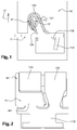
- the conductive strip 11 and the contact spring 12 are configured so that when the electrical conductor is inserted into the housing 10 at the first orifice, the elastic portion 121 of the contact spring 12 is deformed to allow the contact spring 12 on the one hand to open automatically under the action of the outer force insertion of the electrical conductor to allow to place the electrical conductor in the contact position, and secondly to exert a pressure force on the electrical conductor ensuring the maintenance of the electrical conductor in its contact position
- the contact spring 12 is configured so that the contact between the electrical conductor and the conductive strip 11 results from a force insertion of the electrical conductor in opposition to the action of the contact spring 12 and is automatically held by the contact spring 12 after insertion of the electrical conductor.
- the insertion of the electrical conductor is practiced between a portion of the contact spring 12 and the conductive strip 11, so that the electrical conductor is directly gripped by and between these two parts. This is the contact position mentioned above.
- the housing 10 is illustrated schematically and the first and second orifices are not shown.
- the nature and organization of the elastic portion 121 of the contact spring 12 are not limiting either and can be any as soon as the contact spring 121 meets the functions presented in a general manner previously.
- the organization of the elastic portion 121 may be a function of the material and the shape of the contact spring 12, the expected thickness of the electrical conductors to be maintained, the desired pressure force to maintain the electrical conductor in its position contact, the shape and design of the housing 10 and the conductive strip 11, etc.
- the contact spring 12 is able to vary between a first rest configuration (shown in the figures) from which it can open under the effect of the insertion action of the electrical conductor to come to occupy a second configuration (not shown) in which the contact spring 12 exerts a pressure force of the electrical conductor against the conductive strip 11, and a third configuration in which the electrical conductor is free to be removed from the connection terminal.
- the variation of the contact spring 12 from one configuration to another is practiced by elastic deformation at its portion 121 elastically deformable.
- the contact spring 12 is configured so as to be continuously biased towards the first elastically resilient configuration of its material at the portion 121.
- the pressure force exerted on the electrical conductor by the contact spring 12 in its second configuration is adapted to ensure the maintenance of the electrical conductor in the connection terminal, in particular by clamping between the contact spring 12 and the conductive strip 11, to prevent its axial withdrawal from the connection terminal.
- the contact spring 12 is removably mounted on the conductive strip 11.
- the electrical conductor can for example come into a slot 111 formed in the conductive strip 11 and be held by the contact spring 12 itself. mounted on the conductive strip 11.
- the conductive strip 11 may comprise a contact portion 112 extending from an edge of the slot 111 and directed in a direction opposite to the direction of insertion of the electrical conductor into the slot 111. The electrical conductor comes against the contact portion 112 when the contact spring 12 exerts the pressing force to maintain it in the contact position.
- the contact spring 12 and the conductive strip 11 comprise elements making it possible to fix the contact spring 12 on an edge of the light 111 in a demountable manner, for example by means of a snap-fit system equipping the contact spring for this purpose. 12 and / or the conductive strip 11.
- the housing 10 delimits at least a second orifice allowing the insertion of a tool (not shown) in the housing 10 such as a screwdriver until it comes against the contact spring 12 in an area thereof. ci such that the passage of the contact spring 12 to its third configuration results from a pressing action of the tool on this area of the contact spring 12, which corresponds to the external force in the case where it applied not by the electrical conductor but by the tool, having an intensity greater than a predetermined value. This predetermined value depends on the design and organization of the contact spring 12.
- the electrical apparatus comprises a support clip 13 independent of the housing 10 and the conductive strip 11, having further detailed fasteners configured so as to mount the support clip 13 to the contact spring 12, particularly reversibly.
- the support clip 13 is configured to define a bearing face 131 against which the contact spring 12 is supported during the deformation of its elastic portion 121 under the action of the external force, to impose the manner in which the elastic portion 121 of the contact spring 12 is deformed spatially and against which the contact spring 12 abuts in its state of maximum deformation to limit the elastic deformation of the elastic portion 121 of the contact spring 12 below a value predetermined regardless of the intensity of the external force imposed by the electrical conductor or by the unlocking tool.
- the predetermined value below which the elastic deformation is contained by means of the support staple 13 depends in particular on the material, the shape and the thickness of the contact spring 12 in its elastic part 121, but also on the shape of the support clip 13 at the bearing face 131 where it fulfills the function of guiding and limiting the elastic deformation.
- limiting the elastic deformation corresponds in practice to ensuring that at any point of the elastic portion 121 of the contact spring 12, the values taken by the terms of the tensor deformation remain individually lower than a predetermined value during the phase of elastic deformation imposed by the mechanical force applied by the electrical conductor when the latter itself undergoes the insertion force or by the mechanical force applied by the unlocking tool.
- the support staple 13 is formed of an electrically insulating material, for example a plastic material for reasons of ease of manufacture.
- the shape of the support clip 13 depends on the shape of the contact spring 12 and is not a function of the shape of the conductive strip 11.
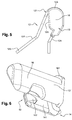
- the support clip 13 is a one-piece integral piece. This piece is independent and separate from the housing 10, the conductive strip 11 and the contact spring 12. The figure 6 illustrates this independent piece, adapted to be mounted on the contact spring 12 and to be disassembled.
- the support staple 13 and the contact spring 12 are configured so that the support staple 13 is fixed to the contact spring 12 by a relative movement of the support staple 13 relative to the contact spring 12 in a lateral mounting direction substantially perpendicular to a deformation plane in which the contact spring 12 deforms during the elastic deformation of its elastic portion 121 under the action of the external force.
- the shape of the contact spring 12 is not limiting in itself, it will depend in particular on that of the conductive strip 11 or the electrical conductor to insert and maintain. That said, it has been found that good results are achieved by providing that the contact spring 12 comprises at least one elongated blade 122, at which all or part of the resilient portion 121 of the contact spring 12 is arranged.
- the support staple 13 is fixed on said at least one blade 122 to occupy a functional position relative to the blade 122 in which the support staple 13 blocks and limits the elastic deformation of the blade 122 when the elastic portion 121 of the contact spring 12 is deformed under the action of the external force.
- each blade 122 may be arbitrary provided that it serves to fulfill its general function as presented here.
- the contact spring 12 comprising at least one such blade 122, each of its blades 122 may be bent along its length to define a bend 123, as is the case in the figures.
- the angle adopted by the elbow 123 of each blade 122 can in particular be of the order of 180 °.
- the support staple 13 is then housed in this elbow 123 when it occupies its functional position.
- each blade 122 constitutes the part of the contact spring 12 intended to bear against the electrical conductor in the second configuration of the spring 12. At least the elbow 123 of each blade 122 forms the elastic portion dedicated to the passage from one configuration to another of the contact spring 12.
- a "blade” corresponds to a substantially elongated portion, having a larger dimension than the other dimensions, comparable to its length.
- the longitudinal direction X of the blade 122 corresponds locally to the direction of extension or elongation of the blade 122, according to which the length is considered.
- the smallest dimension of the blade 122 similar to its thickness, is counted locally in the transverse direction Z of the blade 122.
- the direction simultaneously perpendicular to the longitudinal direction X of the blade 122 and its transverse direction Z is the direction Lateral Y of the blade 122.
- the size of the blade 122, counted in the lateral direction Y of the blade 122, is comparable to the width of the blade 122.
- the length of the blade 122 in the longitudinal direction X is much greater than the width of the blade 122 in its lateral direction Y, itself being much greater than the thickness of the blade 122 counted in the transverse direction Z.
- the deformation plane mentioned above, in which the contact spring 12 deforms during the application of the external force, is a plane oriented along the longitudinal direction X and the transverse direction Z.
- the lateral direction Y is perpendicular to this plane of deformation.
- the support staple 13 is mounted on said at least one blade 122 in the lateral direction Y of this blade 122 until it comes to occupy its functional position, this movement being perpendicular to the deformation plane of the contact spring 12 More specifically, a main body 16 of the support staple 13 is inserted into the elbow 123 formed in each of the blades 122 in their lateral direction Y. In this movement, the main body 16 abuts against one of the edges side of one of the blades 122 at a stop 161 of the main body 16 when it reaches the end of insertion, so that the functional position of the support clip 13 corresponds to an exactly predetermined spatial position relative to to the contact spring 12.
- fastening elements of the support staple 13 on the contact spring 12 may be arbitrary and non-limiting, the embodiment shown is advantageous in terms of simplicity and efficiency in providing that the fastening elements comprise hooking elements 14 in the form of a hook secured to the support clip 13 and arranged to engage reversibly in an area complementary to the contact spring 12.
- the hooking elements 14 in the form of hooks are connected to the main body 16, in particular at its end equipped with the abutment 161. They comprise a wall 141 substantially parallel to the main body 16 and separated therefrom by an interval sufficient to be greater than the thickness of 122 blades and allow their establishment between the main body 16 and the wall 141, thus constituting the general form of hook.
- the attachment elements further comprise a retaining pin 142 (visible on the figure 6 ) projecting from the wall 141 towards the main body 16.
- the function of this retaining pin 142 is to constitute a stop for the support clip 13 in a direction opposite to the stop 161, to axially block the movement of the support clip 13 bidirectionally in the contact spring 12 in the lateral direction Y of the blades 122.
- the fastening elements of the support clip 13 on the contact spring 12 also comprise at least one support element secured to the support clip 13 configured to press against the contact spring 12 to prevent tilting of the support staple 13 with respect to the contact spring 12 under the effect of the weight of the support staple 13.
- the support element is constituted by a protrusion 151 of the support clip 13 configured to bear against a portion of the contact spring 12 projecting from said at least one blade 122 in the direction lateral Y of the blade 122, this support acting in the longitudinal direction X of the blade 122.
- the protrusion 151 comes in particular from material with the rest of the support clip 13.
- the protrusion 151 may for example project protruding from the end of the wall 141 and being oriented substantially in the same plane as the wall 141.
- the contact spring 12 comprises two blades 122 connected to one another by a connecting portion 124, at their level. opposite ends to the free ends 125.
- the portion of the spring 12 against which the protrusion 151 bears is arranged at this connecting portion 124 between the two blades 122.
- the protrusion 151 of the clip 13 is inserted in a slot 126 separating the two blades 122 between them in the lateral direction Y of the blades 122 and comes longitudinally bear against the connecting portion 124 to prevent the tilting of the support clip 13 under the effect of its weight.
- the mounting of the contact spring 12 on the conductive strip 11 is formed at the connecting portion 124 between the blades 122, this mounting being for example on a free edge of the light 111 mentioned above, at the level of which the electrical conductor comes to occupy its position of contact.
- the execution mode of the figure 8 provide that the support element is constituted by an outer cap 152 of the support clip 13 configured to surround the elbow 123 delimited by each blade 122 and resting on the outer face of the elbow 123, this support acting along the transverse direction Z of the blade 122.
- This outer cap 152 is integral with the rest of the clip 13 and is connected to the main body 16 near its abutment 161. It is substantially parallel to the main body 16 and separated therefrom by a gap sufficient to be greater than 1 the thickness of the blades 122 and allow their placement between the main body 16 and the outer cap 152 in their lateral direction Y.
- the housing 10 may comprise two parts assembled to one another in a mounting direction 17 (FIG. figure 1 ) oriented substantially parallel to the direction of movement of the electrical conductor during its insertion to its contact position.
- the housing 10 comprises for example a peripheral wall and a cover configured so as to be assembled to each other in a mounting direction 17 substantially parallel to the direction in which the electrical conductor is inserted into the connection terminal.
- the assembly of the cover with the peripheral wall can be achieved by any suitable mechanism such as a latching system, screwing or equivalent.
- this direction of assembly 17 thus oriented is optional and it remains possible to provide that the two parts of the housing 10 are configured so as to assemble one with the other. another in a mounting direction substantially perpendicular to the direction of insertion of the electrical conductor into the connection terminal.
- the mounting direction of the assembly consisting of the contact spring 12 and the support clip 13 assembled together to come up in the housing 10 is oriented substantially parallel to the direction moving the electrical conductor during its insertion to its contact position.
- the invention which has just been described is an alternative solution to those of the prior art which allows a reduction in costs, space and weight. It is simple to design and use, while being user-friendly and ergonomic in practice.
- the support clip 13 gives all the necessary safety against the risk of deterioration of the contact spring 12 under the effect of the different external forces applied to the contact spring 12 in the insertion and removal phases of the electrical conductor: especially avoids any risk of plastic deformation through the function of guiding and limiting the elastic deformation.
- each connection terminal is of the pressure type, which makes it possible to achieve the results sought above in a very efficient manner, in particular when the two parts of the housing 10 must be assembled in the same direction as the insertion direction.
- electrical conductor in the connection terminal which is the case frequently for electrical contactors.
- the means for securing the contact spring 12 against the risk of plastic deformation, that is to say here the support clip 13, very advantageously allow a mounting of the pressure type connection terminal and the bar conductive 11 in the housing 10 otherwise than laterally, in particular in the same direction as the direction in which the electrical conductor is inserted into the connection terminal and that the two parts of the housing 10 are assembled together.
Landscapes
- Connector Housings Or Holding Contact Members (AREA)
- Coupling Device And Connection With Printed Circuit (AREA)
- Details Of Connecting Devices For Male And Female Coupling (AREA)
Priority Applications (3)
| Application Number | Priority Date | Filing Date | Title |
|---|---|---|---|
| EP16305168.3A EP3206260A1 (fr) | 2016-02-15 | 2016-02-15 | Appareil électrique ayant une borne de connexion à pression avec une agrafe de support guidant et limitant la déformation élastique du ressort de contact |
| US15/432,617 US10027041B2 (en) | 2016-02-15 | 2017-02-14 | Electrical apparatus having a push-in connection terminal with a support clip guiding and limiting the elastic deformation of the contact spring |
| CN201710080561.0A CN107086417A (zh) | 2016-02-15 | 2017-02-15 | 具有嵌入式接线端子的电气设备,接线端子带有引导和限制接触弹簧的弹性变形的支撑夹 |
Applications Claiming Priority (1)
| Application Number | Priority Date | Filing Date | Title |
|---|---|---|---|
| EP16305168.3A EP3206260A1 (fr) | 2016-02-15 | 2016-02-15 | Appareil électrique ayant une borne de connexion à pression avec une agrafe de support guidant et limitant la déformation élastique du ressort de contact |
Publications (1)
| Publication Number | Publication Date |
|---|---|
| EP3206260A1 true EP3206260A1 (fr) | 2017-08-16 |
Family
ID=55359483
Family Applications (1)
| Application Number | Title | Priority Date | Filing Date |
|---|---|---|---|
| EP16305168.3A Withdrawn EP3206260A1 (fr) | 2016-02-15 | 2016-02-15 | Appareil électrique ayant une borne de connexion à pression avec une agrafe de support guidant et limitant la déformation élastique du ressort de contact |
Country Status (3)
| Country | Link |
|---|---|
| US (1) | US10027041B2 (zh) |
| EP (1) | EP3206260A1 (zh) |
| CN (1) | CN107086417A (zh) |
Cited By (2)
| Publication number | Priority date | Publication date | Assignee | Title |
|---|---|---|---|---|
| WO2019105826A1 (de) * | 2017-11-28 | 2019-06-06 | Weidmüller Interface GmbH & Co. KG | Anschlussvorrichtung zum anschluss eines leiterendes |
| EP4346015A1 (en) * | 2022-09-29 | 2024-04-03 | Switchlab Inc. | Electrical contact assembly structure of terminal device |
Families Citing this family (4)
| Publication number | Priority date | Publication date | Assignee | Title |
|---|---|---|---|---|
| DE202015105023U1 (de) * | 2015-09-22 | 2016-12-23 | Weidmüller Interface GmbH & Co. KG | Anschlussvorrichtung für Leiter |
| JP6992621B2 (ja) * | 2018-03-14 | 2022-01-13 | オムロン株式会社 | 接続子およびソケット |
| TWI659581B (zh) * | 2018-03-16 | 2019-05-11 | 進聯工業股份有限公司 | Conductive component structure of wire coupling device |
| DE102018124623B4 (de) * | 2018-10-05 | 2022-07-07 | Wago Verwaltungsgesellschaft Mbh | Kontakteinsatz einer Leiteranschlussklemme sowie damit gebildete Leiteranschlussklemme |
Citations (4)
| Publication number | Priority date | Publication date | Assignee | Title |
|---|---|---|---|---|
| FR2792778A1 (fr) * | 1999-04-22 | 2000-10-27 | Schneider Electric Sa | Borne elastique d'appareil electrique |
| DE102005016534A1 (de) * | 2005-04-08 | 2006-10-12 | Wago Verwaltungsgesellschaft Mbh | Elektrische Reihenklemmen |
| US20140127932A1 (en) * | 2011-06-21 | 2014-05-08 | Phoenix Contact Gmbh & Co. Kg | Electrical connection terminal |
| FR3012686A1 (fr) * | 2013-10-29 | 2015-05-01 | Abb France | Appareil electrique comprenant une borne de raccordement a ressort |
Family Cites Families (21)
| Publication number | Priority date | Publication date | Assignee | Title |
|---|---|---|---|---|
| US5494456A (en) * | 1994-10-03 | 1996-02-27 | Methode Electronics, Inc. | Wire-trap connector with anti-overstress member |
| FR2787932B1 (fr) * | 1998-12-23 | 2001-03-09 | Entrelec Sa | Ressort de connexion |
| US6074242A (en) * | 1998-12-31 | 2000-06-13 | Methode Electronics, Inc. | Wire-trap connector for solderless compression connection |
| DE20106710U1 (de) * | 2001-04-18 | 2001-08-09 | Phoenix Contact Gmbh & Co | Elektrische Klemme |
| US6786779B2 (en) * | 2002-06-20 | 2004-09-07 | Tyco Electronics Amp Gmbh | Electrical plug connector with spring tension clamp |
| US6719581B2 (en) * | 2002-07-25 | 2004-04-13 | Nippon Dics Co., Ltd. | Plug for speaker cables, and speaker terminal and speaker terminal system provided with them |
| WO2005011067A1 (ja) | 2003-07-24 | 2005-02-03 | Nippon Dics Co., Ltd. | スピーカケーブル用プラグと該プラグを受入れるスピーカ端子、並びに、前記プラグと端子によるスピーカターミナルシステム |
| DE102004046471B3 (de) | 2004-09-23 | 2006-02-09 | Phoenix Contact Gmbh & Co. Kg | Elektrische Anschluß- oder Verbindungsklemme |
| DE102005045596B3 (de) | 2005-09-23 | 2007-06-21 | Siemens Ag | Feder-Steckklemme |
| DE202006009460U1 (de) | 2005-10-29 | 2007-03-15 | Weidmüller Interface GmbH & Co. KG | Anschlussvorrichtung für Leiter |
| TWI449281B (zh) | 2006-04-25 | 2014-08-11 | Wago Verwaltungs Gmbh | Electronic connector |
| US7255592B1 (en) | 2006-05-19 | 2007-08-14 | Heavy Power Co., Ltd. | Electrical wire connector |
| DE102006047254B3 (de) | 2006-10-06 | 2008-05-21 | Abb Ag | Installationsschaltgerät |
| DE102008017245B4 (de) | 2008-04-04 | 2010-03-25 | Moeller Gmbh | Steckadapter für ein elektrisches Schaltgerät |
| US7699635B2 (en) | 2008-09-23 | 2010-04-20 | The Boeing Company | Randomly-accessible electrical busbar with protective cover and associated mating connector |
| DE102009004513A1 (de) | 2009-01-09 | 2010-07-22 | Phoenix Contact Gmbh & Co. Kg | Klemmfeder für eine Federkraftklemme |
| US7806711B2 (en) | 2009-02-27 | 2010-10-05 | American Power Conversion Corporation | Electrical connector |
| DE102009050367A1 (de) * | 2009-10-22 | 2011-04-28 | Phoenix Contact Gmbh & Co. Kg | Federkraftanschlussklemme |
| US20120208394A1 (en) | 2011-02-15 | 2012-08-16 | Heavy Power Co., Ltd. | Reusable double-contact electrical wire connector for single-and multi-thread wires |
| SG2012065942A (en) | 2012-09-05 | 2014-04-28 | Schneider Electric South East Asia Hq Pte Ltd | An electrical connector and a connector assembly |
| JP6572697B2 (ja) | 2015-09-15 | 2019-09-11 | オムロン株式会社 | ソケット |
-
2016
- 2016-02-15 EP EP16305168.3A patent/EP3206260A1/fr not_active Withdrawn
-
2017
- 2017-02-14 US US15/432,617 patent/US10027041B2/en not_active Expired - Fee Related
- 2017-02-15 CN CN201710080561.0A patent/CN107086417A/zh active Pending
Patent Citations (4)
| Publication number | Priority date | Publication date | Assignee | Title |
|---|---|---|---|---|
| FR2792778A1 (fr) * | 1999-04-22 | 2000-10-27 | Schneider Electric Sa | Borne elastique d'appareil electrique |
| DE102005016534A1 (de) * | 2005-04-08 | 2006-10-12 | Wago Verwaltungsgesellschaft Mbh | Elektrische Reihenklemmen |
| US20140127932A1 (en) * | 2011-06-21 | 2014-05-08 | Phoenix Contact Gmbh & Co. Kg | Electrical connection terminal |
| FR3012686A1 (fr) * | 2013-10-29 | 2015-05-01 | Abb France | Appareil electrique comprenant une borne de raccordement a ressort |
Cited By (2)
| Publication number | Priority date | Publication date | Assignee | Title |
|---|---|---|---|---|
| WO2019105826A1 (de) * | 2017-11-28 | 2019-06-06 | Weidmüller Interface GmbH & Co. KG | Anschlussvorrichtung zum anschluss eines leiterendes |
| EP4346015A1 (en) * | 2022-09-29 | 2024-04-03 | Switchlab Inc. | Electrical contact assembly structure of terminal device |
Also Published As
| Publication number | Publication date |
|---|---|
| US20170237186A1 (en) | 2017-08-17 |
| CN107086417A (zh) | 2017-08-22 |
| US10027041B2 (en) | 2018-07-17 |
Similar Documents
| Publication | Publication Date | Title |
|---|---|---|
| EP3206260A1 (fr) | Appareil électrique ayant une borne de connexion à pression avec une agrafe de support guidant et limitant la déformation élastique du ressort de contact | |
| EP2528166B1 (fr) | Clip de mise à la terre et assemblage de mise à la terre | |
| EP3807956A1 (fr) | Clip metallique de connexion electrique d'un fil conducteur a un element metallique | |
| EP1916743B1 (fr) | Appareil électrique comprenant au moins une borne de raccordement à ressort | |
| EP1622224A1 (fr) | Appareil électrique comportant une borne à connexion automatique | |
| EP1912299B1 (fr) | Appareil électrique, destiné à être fixé sur un rail support, et procédé de montage correspondant | |
| EP1867009B1 (fr) | Dispositif de serrage pour une borne de raccordement | |
| EP3206259B1 (fr) | Contacteur électrique avec une borne de connexion à pression montée dans un boitier à deux parties assemblées suivant la direction d'insertion d'un conducteur électrique dans la borne de connexion | |
| EP2849287B1 (fr) | Dispositif de raccordement électrique d'au moins un conducteur dans une borne appartenant à un appareil électrique | |
| EP0684662A1 (fr) | Connecteur autodénudant | |
| EP0772256A2 (fr) | Appareil électrique à bornes de raccordement protégées par un diaphragme à fixation par des ailes | |
| FR2954604A1 (fr) | Borne de connexion electrique automatique et appareillage electrique comportant une telle borne | |
| EP3598582B1 (fr) | Dispositif de connexion électrique | |
| EP0908965A1 (fr) | Borne de connexion à serrage automatique | |
| EP3529867B1 (fr) | Appareil electrique comprenant un dispositif de verrouillage pour rail de fixation | |
| EP1424756A1 (fr) | Dispositif de raccordement électrique d'un appareil électrique modulaire à un peigne de raccordement ou analogue | |
| EP1928058B9 (fr) | Borne de connexion électrique automatique | |
| FR2919438A1 (fr) | Outil de demontage pour des contacts a encastrement | |
| EP1729359B1 (fr) | Dispositif de retenue et de connexion pour pile | |
| WO1996019019A1 (fr) | Fiche electrique du type fiche anglaise | |
| EP1198030B1 (fr) | Connecteur à ressort à cage comportant une plaque rapportée à la lame ressort | |
| FR3060872A1 (fr) | Element de connexion electrique | |
| EP3349306B1 (fr) | Appareil électrique modulaire | |
| FR3028356A1 (fr) | Borne de connexion electrique a vis imperdable | |
| FR2709601A1 (fr) | Cosse pour batterie. |
Legal Events
| Date | Code | Title | Description |
|---|---|---|---|
| PUAI | Public reference made under article 153(3) epc to a published international application that has entered the european phase |
Free format text: ORIGINAL CODE: 0009012 |
|
| AK | Designated contracting states |
Kind code of ref document: A1 Designated state(s): AL AT BE BG CH CY CZ DE DK EE ES FI FR GB GR HR HU IE IS IT LI LT LU LV MC MK MT NL NO PL PT RO RS SE SI SK SM TR |
|
| AX | Request for extension of the european patent |
Extension state: BA ME |
|
| 17P | Request for examination filed |
Effective date: 20180214 |
|
| RBV | Designated contracting states (corrected) |
Designated state(s): AL AT BE BG CH CY CZ DE DK EE ES FI FR GB GR HR HU IE IS IT LI LT LU LV MC MK MT NL NO PL PT RO RS SE SI SK SM TR |
|
| 17Q | First examination report despatched |
Effective date: 20190412 |
|
| STAA | Information on the status of an ep patent application or granted ep patent |
Free format text: STATUS: THE APPLICATION IS DEEMED TO BE WITHDRAWN |
|
| 18D | Application deemed to be withdrawn |
Effective date: 20191023 |