EP3206090A1 - Mouvement d'horlogerie comportant deux balanciers - Google Patents
Mouvement d'horlogerie comportant deux balanciers Download PDFInfo
- Publication number
- EP3206090A1 EP3206090A1 EP17155218.5A EP17155218A EP3206090A1 EP 3206090 A1 EP3206090 A1 EP 3206090A1 EP 17155218 A EP17155218 A EP 17155218A EP 3206090 A1 EP3206090 A1 EP 3206090A1
- Authority
- EP
- European Patent Office
- Prior art keywords
- plane
- wheel
- rockers
- movement according
- axis
- Prior art date
- Legal status (The legal status is an assumption and is not a legal conclusion. Google has not performed a legal analysis and makes no representation as to the accuracy of the status listed.)
- Withdrawn
Links
- 230000001154 acute effect Effects 0.000 claims description 3
- 238000012423 maintenance Methods 0.000 abstract description 6
- 230000001105 regulatory effect Effects 0.000 description 6
- 230000008878 coupling Effects 0.000 description 1
- 238000010168 coupling process Methods 0.000 description 1
- 238000005859 coupling reaction Methods 0.000 description 1
- 230000000694 effects Effects 0.000 description 1
- 239000000155 melt Substances 0.000 description 1
- 238000004804 winding Methods 0.000 description 1
Images


Classifications
-
- G—PHYSICS
- G04—HOROLOGY
- G04B—MECHANICALLY-DRIVEN CLOCKS OR WATCHES; MECHANICAL PARTS OF CLOCKS OR WATCHES IN GENERAL; TIME PIECES USING THE POSITION OF THE SUN, MOON OR STARS
- G04B17/00—Mechanisms for stabilising frequency
- G04B17/04—Oscillators acting by spring tension
- G04B17/06—Oscillators with hairsprings, e.g. balance
-
- G—PHYSICS
- G04—HOROLOGY
- G04B—MECHANICALLY-DRIVEN CLOCKS OR WATCHES; MECHANICAL PARTS OF CLOCKS OR WATCHES IN GENERAL; TIME PIECES USING THE POSITION OF THE SUN, MOON OR STARS
- G04B17/00—Mechanisms for stabilising frequency
- G04B17/20—Compensation of mechanisms for stabilising frequency
- G04B17/26—Compensation of mechanisms for stabilising frequency for the effect of variations of the impulses
Definitions
- the present invention relates to a watch movement, more particularly of the type comprising two rockers.
- EP2141555 discloses a timepiece resonator resulting from the coupling of a first spiral balance disposed coaxially with a second balance spring each spirals having a different frequency.
- WO2015049090 which describes a clockwork movement comprising a barrel, a first regulating member and a first escapement connected by a first wheel to said energy source.
- the first wheel, the first escapement and the first regulating member define a first set.
- the movement further comprises a second regulating member and a second escapement connected by a second wheel to the same barrel.
- the second wheel, the second escapement and the second regulating member define a second set.
- the first and second sets are arranged one above the other.
- the object of the present invention is to provide a watch movement comprising two rockers arranged one above the other offering better isochronism due to the average running of the two regulating members and providing a strong aesthetic effect.
- a clockwork movement comprises a source of mechanical energy including a barrel, two rockers, two escapements respectively providing maintenance of a rocker, and mobiles connecting the source of mechanical energy to the exhausts comprising a second wheel defining a plane (A) parallel to a bottom of the box.
- the two rockers are arranged on both sides of the plane (A) and are inclined relative to said plane (A).
- each escapement connecting the balance wheel to the second wheel is either parallel to the barrel or parallel to the second wheel.
- the escapement comprises an anchor, one end of which extends along a plane inclined with respect to said plane (A).
- first balance wheel rotates about a first axis
- second balance rotates about a second axis
- each balance axis intercepting the plane (A) to form an acute angle typically between 20 ° and 85 °.
- each balance is parallel to the escapement connecting it to the second wheel, the second wheel having a conical toothing meshing the exhaust.
- the first balance wheel rotates about a first axis
- the second balance rotates about a second axis
- each balance axis intercepting the plane (A) to form an obtuse angle typically between 100 ° and 160 °.
- a watch movement comprises a barrel 10, two balance-springs 1, 2, two exhausts 3, 4 respectively ensuring the maintenance of a balance 1, 2, and wheeling wheels of finishing namely a center wheel 9, an average wheel 8 and two second wheels 7a, 7b connecting the barrel 10 to the escapements 3, 4.
- the second wheels 7a, 7b define a plane (A) parallel to a bottom of the box in which the movement will be housed .
- the two balance-springs 1, 2 are arranged on both sides of the plane A and are inclined relative to said plane A.
- Each escapement 3, 4 connects, in particular by anchors 13, 14, a balance 1, 2 to a second wheel 7a, 7b.
- the balance springs 1, 2 are respectively parallel to the escapements 3, 4 and the anchors 13, 14.
- the inclination of the balance-springs 1, 2 is achieved by a conical toothing on each second wheel 7a, 7b.
- the spirals 11, 12 of the regulating members are arranged on opposite parts with respect to each other, one side melts the other side of a watch.
- the watch movement comprises a barrel 10, two balance-springs 1, 2, two exhausts 3, 4 respectively ensuring the maintenance of a balance 1, 2, and wheeling wheels 7a, 7b, 8, 9 each connecting the barrel 10 to the exhausts 3, 4.
- Each escapement comprises an anchor 13, 14 comprising, as is customary, a rod which at one end, two pallets are fitted in two notched arms. At the free end 13a, 14a of the rod, opposite the pallets, there is a usual fork having inlet and outlet horns and a stinger. The end of the rod has two vanes extending in the plane (A) and the free end of the rod has the fork extending in a plane inclined relative to said plane (A).
- each anchor 13, 14 is driven on a rod, the rods being coaxial with respect to each other.
- the inclination can be done at the level of the plate or ellipse pin. According to this variant, the anchor is therefore parallel to the exhaust.
- first and second pendulums 1, 2 rotate respectively about a first and second axis 100, 200, ( figure 2 ) each balance shaft 100, 200 intercepting the plane (A) to form an acute angle ⁇ of about 70 °.
- the point of intersection Y ( figure 2 ) of two straight lines connecting the two axes of rockers 1, 2 is further from the axis of the center wheel 9 than the point of intersection X of two planes B1, B2 each representing the rockers 1, 2.
- the watch movement comprises a barrel 10, two balance-springs 1, 2, two exhausts 3, 4 respectively ensuring the maintenance of a balance 1, 2, and wheeling wheels 7a, 7b, 8, 9 connecting the barrel 10 to the escapements 3, 4.
- the first rocker 1 rotates about a first axis 100
- the second rocker rotates about a second axis 200.
- Each balance shaft intercepts the plane (A) to form an obtuse angle ⁇ of about 110 °.
- the point of intersection Y of two straight lines connecting the two axes of the rockers 1, 2 is closer to the axis of the center wheel 9 than the point of intersection X of two planes B1, B2 representing each pendulums 1, 2.
- each of the two rockers 1, 2 of the movement is mounted symmetrically with respect to the other with respect to the plane (A).
- the rockers 1, 2 are arranged on a lower part of a watch display, in particular on the zone of the display 6H, perpendicularly to a winding stem 20 ( figure 1 ), especially in the case where the movement is at least partially visible through the dial.
- the watch movement comprises a barrel 10, two balance-springs 1, 2, two exhausts 3, 4 respectively ensuring the maintenance of a balance 1, 2, and wheeling wheels 7a, 7b, 8, 9 connecting the barrel 10 to the exhausts 3, 4.
- the rockers 1, 2 are mounted symmetrically on either side of a straight line D ( figure 9 ) passing through the center of the mechanical power source and the center of the second wheel 7a, 7b.
- the watch movement may comprise several rockers, at least two of which are arranged one above the other, each rocker being able to have a different inclination then coming out of the illustrated examples where there is a symmetry between each pair of rockers. pendulums.
- the movement can be applied to all kinds of timepieces, including wristwatches.
Landscapes
- Physics & Mathematics (AREA)
- General Physics & Mathematics (AREA)
- Micromachines (AREA)
- Transmission Devices (AREA)
Abstract
Un mouvement d'horlogerie comprend une source d'énergie mécanique (10) notamment un barillet, deux balanciers (1, 2), deux échappements (3, 4) assurant respectivement l'entretien d'un balancier (1, 2), et des mobiles (7a, 7b, 8, 9) reliant ladite source d'énergie (10) aux échappements (3, 4) comportant une roue de seconde (7a, 7b) définissant un plan (A) parallèle à un fond de la boite. Les deux balanciers (1, 2) sont disposés de part et d'autre du plan (A) et sont inclinés par rapport audit plan (A).
Description
- La présente invention se rapporte à mouvement d'horlogerie, plus particulièrement du type comportant deux balanciers.
- On connaît ainsi par exemple
EP2141555 qui décrit un résonateur pour pièce d'horlogerie résultant du couplage d'un premier balancier spiral disposé coaxialement à un second balancier spiral chacun des balanciers spiraux ayant une fréquence différente. - On connaît également
WO2015049090 qui décrit un mouvement d'horlogerie comprenant un barillet, un premier organe réglant et un premier échappement reliés par un premier rouage à ladite source d'énergie. Le premier rouage, le premier échappement et le premier organe réglant définissent un premier ensemble. Le mouvement comporte en outre un deuxième organe réglant et un deuxième échappement reliés par un deuxième rouage au même barillet. Le deuxième rouage, le deuxième échappement et le deuxième organe réglant définissent un deuxième ensemble. Les premiers et seconds ensembles sont disposés l'un au-dessus de l'autre. - Le but de la présente invention est de proposer un mouvement d'horlogerie comportant deux balanciers disposés l'un au-dessus de l'autre offrant un meilleur isochronisme du fait de la moyenne de marche des deux organes réglants et procurant un effet esthétique fort.
- Conformément à l'invention, un mouvement d'horlogerie comprend une source d'énergie mécanique notamment un barillet, deux balanciers, deux échappements assurant respectivement l'entretien d'un balancier, et des mobiles reliant la source d'énergie mécanique aux échappements comportant une roue de seconde définissant un plan (A) parallèle à un fond de la boite. Les deux balanciers sont disposés de part et d'autre du plan (A) et sont inclinés par rapport audit plan (A).
- Dans une forme d'exécution, chaque échappement reliant le balancier à la roue de seconde est soit parallèle au barillet soit parallèle à la roue de seconde.
- Dans une forme d'exécution, l'échappement comporte une ancre dont une extrémité s'étend selon un plan incliné par rapport audit plan (A).
- Dans une autre forme d'exécution, le premier balancier tourne en rotation autour d'un premier axe, le second balancier tourne en rotation autour d'un second axe, chaque axe de balancier interceptant le plan (A) pour former un angle aigu typiquement compris entre 20° et 85°.
- Dans une exécution, chaque balancier est parallèle à l'échappement le reliant à la roue de seconde, la roue de seconde comportant une denture conique engrenant l'échappement.
- Toujours selon cette exécution, le premier balancier tourne en rotation autour d'un premier axe, le second balancier tourne en rotation autour d'un second axe, chaque axe de balancier interceptant le plan (A) pour former un angle obtus typiquement compris entre 100° et 160°.
- Les caractéristiques de l'invention apparaitront plus clairement à la lecture de la description de plusieurs formes d'exécution données uniquement à titre d'exemple, nullement limitative en se référant aux figures schématiques, dans lesquelles :
- La
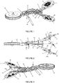
figure 1 représente une vue en perspective simplifiée d'une partie d'un mouvement pour pièce d'horlogerie présentant un agencement de deux balanciers-spiraux inclinés l'un au-dessus de l'autre selon une première forme d'exécution ; - La
figure 2 représente une vue de côté de lafigure 1 ; - La
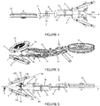
figure 3 représente une vue en perspective simplifiée d'une partie d'un mouvement pour pièce d'horlogerie présentant un agencement de deux balanciers-spiraux inclinés l'un au-dessus de l'autre selon une deuxième forme d'exécution ; - La
figure 4 représente une vue de côté de lafigure 3 ; - La
figure 5 représente une vue en perspective simplifiée d'une partie d'un mouvement pour pièce d'horlogerie présentant un agencement de deux balanciers-spiraux inclinés l'un au-dessus de l'autre selon une troisième forme d'exécution ; - La
figure 6 représente une vue de côté de lafigure 5 ; - La
figure 7 représente une vue en perspective simplifiée d'une partie d'un mouvement pour pièce d'horlogerie présentant un agencement de deux balanciers-spiraux inclinés l'un au-dessus de l'autre et décalés l'un par rapport à l'autre selon une quatrième forme d'exécution ; - La
figure 8 représente une vue de côté de lafigure 7 ; et - La
figure 9 représente une vue de dessus desfigures 7 et9 . - Comme illustré à la
figure 1 , un mouvement d'horlogerie comprend un barillet 10, deux balanciers-spiraux 1, 2, deux échappements 3, 4 assurant respectivement l'entretien d'un balancier 1, 2, et des mobiles de rouage de finissage à savoir une roue de centre 9, une roue de moyenne 8 et deux roues de secondes 7a, 7b reliant le barillet 10 aux échappements 3, 4. Les roues de seconde 7a, 7b définissent un plan (A) parallèle à un fond de boite dans lequel le mouvement sera logé. - Comme illustré à la
figure 2 , les deux balanciers-spiraux 1, 2 sont disposés de part et d'autre du plan A et sont inclinés par rapport audit plan A. Chaque échappement 3, 4 relie, notamment par des ancres 13, 14, un balancier 1, 2 à une roue de seconde 7a, 7b. Les balanciers-spiraux 1, 2 sont respectivement parallèles aux échappements 3, 4 et aux ancres 13, 14. Dans l'exemple illustré auxfigures 1 et 2 , l'inclinaison des balanciers-spiraux 1, 2 est réalisée par une denture conique sur chaque roue de seconde 7a, 7b. Dans cet exemple, les spiraux 11, 12 des organes réglants sont disposés sur des parties opposées l'une par rapport à l'autre, l'un côté fond l'autre côté affichage d'une montre. - Dans l'exemple illustré aux
figures 3 et4 , le mouvement d'horlogerie comprend un barillet 10, deux balanciers-spiraux 1, 2, deux échappements 3, 4 assurant respectivement l'entretien d'un balancier 1, 2, et des mobiles de rouage de finissage 7a, 7b, 8, 9 reliant le barillet 10 aux échappements 3, 4. Chaque échappement comporte une ancre 13, 14 comprenant, comme c'est usuel, une baguette dont à une première extrémité, deux palettes viennent s'ajuster dans deux bras entaillés. A l'extrémité libre 13a, 14a de la baguette, à l'opposé des palettes, il y a une fourchette usuelle comportant des cornes d'entrée et de sortie et un dard. L'extrémité de la baguette comporte deux palettes s'étendant selon le plan (A) et l'extrémité libre de la baguette comporte la fourchette s'étendant selon un plan incliné par rapport audit plan (A). L'inclinaison est réalisée par un angle agencé sur l'extrémité libre 13a, 14a de chaque baguette, plus particulièrement disposée à proximité de l'extrémité comportant la fourchette. Dans cet exemple, chaque ancre 13, 14 est chassée sur une tige, les tiges étant coaxiales l'une par rapport à l'autre. Dans une variante non illustrée, l'inclinaison peut se faire au niveau de la cheville de plateau ou ellipse. Selon cette variante, l'ancre est donc parallèle à l'échappement. - Dans les exemples illustrés aux
figures 1 à 4 , le premier et le second balancier 1, 2 tournent respectivement en rotation autour d'un premier et second axe 100, 200, (figure 2 ) chaque axe de balancier 100, 200 interceptant le plan (A) pour former un angle aigu β d'environ 70°. Dans ces exemples, le point d'intersection Y (figure 2 ) de deux droites reliant les deux axes de balanciers 1, 2 est plus éloigné de l'axe de la roue de centre 9 que le point d'intersection X de deux plans B1, B2 représentant chacun des balanciers 1, 2. - Dans l'exemple illustré aux
figures 5 et 6 , le mouvement d'horlogerie comprend un barillet 10, deux balanciers-spiraux 1, 2, deux échappements 3, 4 assurant respectivement l'entretien d'un balancier 1, 2, et des mobiles de rouage de finissage 7a, 7b, 8, 9 reliant le barillet 10 aux échappements 3, 4. Le premier balancier 1 tourne en rotation autour d'un premier axe 100, le second balancier tourne en rotation autour d'un second axe 200. Chaque axe de balancier intercepte le plan (A) pour former un angle obtus φ d'environ 110°. Dans cet exemple, le point d'intersection Y de deux droites reliant les deux axes de balanciers 1, 2 est plus proche de l'axe de la roue de centre 9 que le point d'intersection X de deux plans B1, B2 représentant chacun des balanciers 1, 2. - Dans les exemples illustrés aux
figures 1 à 6 , chacun des deux balanciers 1, 2 du mouvement, est monté symétrique l'un par rapport à l'autre par rapport au plan (A). Dans ces exemples, les balanciers 1, 2 sont disposés sur une partie basse d'un affichage de montre, en particulier sur la zone de l'affichage 6H, perpendiculairement à une tige de remontoir 20 (figure 1 ), notamment dans le cas où le mouvement est au moins partiellement visible à travers le cadran. - Dans l'exemple illustré aux
figures 7 à 9 , le mouvement d'horlogerie comprend un barillet 10, deux balanciers-spiraux 1, 2, deux échappements 3, 4 assurant respectivement l'entretien d'un balancier 1, 2, et des mobiles de rouage de finissage 7a, 7b, 8, 9 reliant le barillet 10 aux échappements 3, 4. Les balanciers 1, 2 sont montés symétriques de part et d'autre d'une droite D (figure 9 ) passant par le centre de la source d'énergie mécanique et par le centre de la roue de seconde 7a, 7b. - Il est bien évident que la présente invention n'est pas limitée aux exemples de réalisation décrits. Notamment, le mouvement d'horlogerie peut comprendre plusieurs balanciers dont au moins deux sont disposés l'un au-dessus de l'autre, chacun des balanciers pouvant avoir une inclinaison différente sortant alors des exemples illustrés où il existe une symétrie entre chaque paire de balanciers. Le mouvement peut s'appliquer à toute sorte de pièces d'horlogerie, notamment aux montres bracelets.
Claims (12)
- Mouvement d'horlogerie comprenant :- une source d'énergie mécanique (10) notamment un barillet,- deux balanciers (1, 2),- deux échappements (3, 4) assurant respectivement l'entretien d'un balancier (1,2), et- des mobiles (7a, 7b, 8, 9) reliant ladite source d'énergie (10) aux échappements (3, 4) comportant une roue de seconde (7a, 7b) définissant un plan (A) parallèle à un fond de la boite,caractérisé en ce que les deux balanciers (1, 2) sont disposés de part et d'autre du plan (A) et sont inclinés par rapport audit plan (A).
- Mouvement d'horlogerie selon la revendication 1, dans lequel chaque échappement (3, 4) reliant un balancier (1, 2) à la roue de seconde (7a, 7b) est parallèle au balancier (1, 2) ou à ladite roue de seconde (7a, 7b).
- Mouvement d'horlogerie selon l'une des revendications 1 ou 2, dans lequel l'échappement comporte une ancre (13, 14) dont une extrémité s'étend selon un plan incliné par rapport audit plan (A).
- Mouvement d'horlogerie selon l'une des revendications 1 ou 2, dans lequel l'échappement comporte un plateau chassé sur un axe de balancier, le plateau comportant une cheville de plateau coudée coopérant avec une fourchette d'une ancre.
- Mouvement d'horlogerie selon l'une des revendications précédentes, dans lequel le premier balancier (1) est agencé pour rotation autour d'un premier axe (100), le second balancier est agencé pour rotation autour d'un second axe (200), chaque axe de balancier interceptant le plan (A) pour former un angle aigu (β) typiquement compris entre 20° et 85°.
- Mouvement d'horlogerie selon la revendication 5, dans lequel un point d'intersection (Y) de deux droites reliant les deux axes (100, 200) de balanciers est plus éloigné de l'axe de la roue de centre (9) qu'un point d'intersection (X) de deux plans (B1, B2) représentant chacun des balanciers (1, 2).
- Mouvement d'horlogerie selon l'une des revendications 1 à 4, dans lequel le premier balancier (1) est agencé pour rotation autour d'un premier axe (100), le second balancier est agencé pour rotation autour d'un second axe (200), chaque axe de balancier interceptant le plan (A) pour former un angle obtus (φ) typiquement compris entre 100° et 160°.
- Mouvement d'horlogerie selon la revendication 7, dans lequel un point d'intersection (Y) de deux droites reliant les deux axes (100, 200) de balanciers est plus proche de l'axe de la roue de centre (9) que le point d'intersection (X) de deux plans (B1, B2) représentant chacun des balanciers 1, 2.
- Mouvement d'horlogerie selon l'une des revendications précédentes, dans lequel chaque balancier (1, 2) est parallèle à l'échappement (3, 4) le reliant à la roue de seconde (7a, 7b) et dans lequel la roue de seconde (7a, 7b) comporte une denture conique engrenant l'échappement.
- Mouvement d'horlogerie selon l'une des revendications précédentes, dans lequel les balanciers (1, 2) sont montés symétriques par rapport au plan (A).
- Mouvement d'horlogerie selon l'une des revendications 1 à 9, dans lequel les balanciers (1, 2) sont montés symétriques de part et d'autre d'une droite (D) passant par le centre de la source d'énergie mécanique (10) et par le centre de la roue de seconde (7a, 7b).
- Pièce d'horlogerie, notamment une montre, comprenant un mouvement selon l'une des revendications précédentes.
Applications Claiming Priority (1)
| Application Number | Priority Date | Filing Date | Title |
|---|---|---|---|
| CH00165/16A CH712100A2 (fr) | 2016-02-08 | 2016-02-08 | Mouvement d'horlogerie comportant deux balanciers. |
Publications (1)
| Publication Number | Publication Date |
|---|---|
| EP3206090A1 true EP3206090A1 (fr) | 2017-08-16 |
Family
ID=57995128
Family Applications (1)
| Application Number | Title | Priority Date | Filing Date |
|---|---|---|---|
| EP17155218.5A Withdrawn EP3206090A1 (fr) | 2016-02-08 | 2017-02-08 | Mouvement d'horlogerie comportant deux balanciers |
Country Status (2)
| Country | Link |
|---|---|
| EP (1) | EP3206090A1 (fr) |
| CH (1) | CH712100A2 (fr) |
Families Citing this family (1)
| Publication number | Priority date | Publication date | Assignee | Title |
|---|---|---|---|---|
| FR3094804B1 (fr) * | 2019-04-02 | 2021-10-22 | Vianney Halter | « Dispositif de couplage de deux oscillateurs d’horlogerie » |
Citations (6)
| Publication number | Priority date | Publication date | Assignee | Title |
|---|---|---|---|---|
| WO2008101802A2 (fr) * | 2007-02-08 | 2008-08-28 | Complitime Sa | Mouvement de montre |
| EP2141555A1 (fr) | 2008-07-04 | 2010-01-06 | The Swatch Group Research and Development Ltd. | Résonateurs couplés pour pièce d'horlogerie |
| CH704063A1 (fr) * | 2010-11-09 | 2012-05-15 | Complitime Sa | Piece d'horlogerie. |
| EP2615504A1 (fr) * | 2012-01-13 | 2013-07-17 | Manufacture Roger Dubuis S.A. | Mouvement d'horlogerie a balanciers inclinés |
| WO2014180767A1 (fr) * | 2013-05-07 | 2014-11-13 | Hublot Sa, Genève | Mouvement horloger à régulateur à résonance tridimensionnelle |
| WO2015049090A1 (fr) | 2013-10-03 | 2015-04-09 | Gfpi Sa | Mouvement d'horlogerie et piece comprenant un tel mouvement |
-
2016
- 2016-02-08 CH CH00165/16A patent/CH712100A2/fr not_active Application Discontinuation
-
2017
- 2017-02-08 EP EP17155218.5A patent/EP3206090A1/fr not_active Withdrawn
Patent Citations (6)
| Publication number | Priority date | Publication date | Assignee | Title |
|---|---|---|---|---|
| WO2008101802A2 (fr) * | 2007-02-08 | 2008-08-28 | Complitime Sa | Mouvement de montre |
| EP2141555A1 (fr) | 2008-07-04 | 2010-01-06 | The Swatch Group Research and Development Ltd. | Résonateurs couplés pour pièce d'horlogerie |
| CH704063A1 (fr) * | 2010-11-09 | 2012-05-15 | Complitime Sa | Piece d'horlogerie. |
| EP2615504A1 (fr) * | 2012-01-13 | 2013-07-17 | Manufacture Roger Dubuis S.A. | Mouvement d'horlogerie a balanciers inclinés |
| WO2014180767A1 (fr) * | 2013-05-07 | 2014-11-13 | Hublot Sa, Genève | Mouvement horloger à régulateur à résonance tridimensionnelle |
| WO2015049090A1 (fr) | 2013-10-03 | 2015-04-09 | Gfpi Sa | Mouvement d'horlogerie et piece comprenant un tel mouvement |
Also Published As
| Publication number | Publication date |
|---|---|
| CH712100A2 (fr) | 2017-08-15 |
Similar Documents
| Publication | Publication Date | Title |
|---|---|---|
| EP2275879B1 (fr) | Porte-échappement | |
| EP2273323B1 (fr) | Oscillateur mécanique | |
| EP2105806B1 (fr) | Mécanisme d'échappement | |
| EP3206089B1 (fr) | Mécanisme résonateur d'horlogerie | |
| EP2363762A1 (fr) | Pièce d'horlogerie comportant un mouvement mécanique à haute fréquence | |
| EP2652559B1 (fr) | Ancre et échappement muni d'une telle ancre | |
| EP3106931A1 (fr) | Pièce à surface de soudage découplée | |
| EP3208662A1 (fr) | Mouvement d'horlogerie comprenant un dispositif de regulation | |
| CH699165B1 (fr) | Montre squelette. | |
| EP3206090A1 (fr) | Mouvement d'horlogerie comportant deux balanciers | |
| EP3185083B1 (fr) | Mecanisme horloger mecanique avec un echappement a ancre | |
| EP4016195B1 (fr) | Tourbillon pour mouvement horloger | |
| CH707187A2 (fr) | Résonateur de mouvement d'horlogerie et ensemble comprenant un tel résonateur et un mécanisme d'échappement. | |
| EP2607969B1 (fr) | Mouvement horloger à faible sensibilité magnétique | |
| EP1605323A2 (fr) | Spiral pour mouvement d'horlogerie mécanique | |
| EP3709099B1 (fr) | Système oscillant thermocompense | |
| EP3163384B1 (fr) | Guidage flexible en pivotement de mobile horloger | |
| EP2075651A1 (fr) | Mouvement horloger comportant un organe réglant à fréquence d'oscillation élevée | |
| FR3093825A1 (fr) | Systeme oscillant thermocompense | |
| CH702799B1 (fr) | Pièce d'horlogerie comportant un mouvement mécanique à haute fréquence. | |
| CH716149B1 (fr) | Mouvement d'horlogerie comprenant au moins un timbre. | |
| EP3671360A1 (fr) | Remontoir a systeme pare-chocs | |
| EP3663868A1 (fr) | Mouvement d'horlogerie comportant un tourbillon avec une roue magnetique fixe | |
| CH704386A2 (fr) | Assemblage par blocage à cliquet et pièce d'horlogerie comportant un tel assemblage. | |
| CH704677B1 (fr) | Tourbillon pour mouvement horloger muni de moyens de protection contre les chocs. |
Legal Events
| Date | Code | Title | Description |
|---|---|---|---|
| PUAI | Public reference made under article 153(3) epc to a published international application that has entered the european phase |
Free format text: ORIGINAL CODE: 0009012 |
|
| STAA | Information on the status of an ep patent application or granted ep patent |
Free format text: STATUS: THE APPLICATION HAS BEEN PUBLISHED |
|
| AK | Designated contracting states |
Kind code of ref document: A1 Designated state(s): AL AT BE BG CH CY CZ DE DK EE ES FI FR GB GR HR HU IE IS IT LI LT LU LV MC MK MT NL NO PL PT RO RS SE SI SK SM TR |
|
| AX | Request for extension of the european patent |
Extension state: BA ME |
|
| STAA | Information on the status of an ep patent application or granted ep patent |
Free format text: STATUS: THE APPLICATION IS DEEMED TO BE WITHDRAWN |
|
| 18D | Application deemed to be withdrawn |
Effective date: 20180217 |