EP3206050B1 - Gnss-signal-verarbeitung mit deltaphase - Google Patents
Gnss-signal-verarbeitung mit deltaphase Download PDFInfo
- Publication number
- EP3206050B1 EP3206050B1 EP17162542.9A EP17162542A EP3206050B1 EP 3206050 B1 EP3206050 B1 EP 3206050B1 EP 17162542 A EP17162542 A EP 17162542A EP 3206050 B1 EP3206050 B1 EP 3206050B1
- Authority
- EP
- European Patent Office
- Prior art keywords
- rover
- epoch
- difference
- synchronous
- anchor
- Prior art date
- Legal status (The legal status is an assumption and is not a legal conclusion. Google has not performed a legal analysis and makes no representation as to the accuracy of the status listed.)
- Active
Links
Images






Classifications
-
- G—PHYSICS
- G01—MEASURING; TESTING
- G01S—RADIO DIRECTION-FINDING; RADIO NAVIGATION; DETERMINING DISTANCE OR VELOCITY BY USE OF RADIO WAVES; LOCATING OR PRESENCE-DETECTING BY USE OF THE REFLECTION OR RERADIATION OF RADIO WAVES; ANALOGOUS ARRANGEMENTS USING OTHER WAVES
- G01S19/00—Satellite radio beacon positioning systems; Determining position, velocity or attitude using signals transmitted by such systems
- G01S19/38—Determining a navigation solution using signals transmitted by a satellite radio beacon positioning system
- G01S19/39—Determining a navigation solution using signals transmitted by a satellite radio beacon positioning system the satellite radio beacon positioning system transmitting time-stamped messages, e.g. GPS [Global Positioning System], GLONASS [Global Orbiting Navigation Satellite System] or GALILEO
- G01S19/40—Correcting position, velocity or attitude
- G01S19/41—Differential correction, e.g. DGPS [differential GPS]
-
- G—PHYSICS
- G01—MEASURING; TESTING
- G01S—RADIO DIRECTION-FINDING; RADIO NAVIGATION; DETERMINING DISTANCE OR VELOCITY BY USE OF RADIO WAVES; LOCATING OR PRESENCE-DETECTING BY USE OF THE REFLECTION OR RERADIATION OF RADIO WAVES; ANALOGOUS ARRANGEMENTS USING OTHER WAVES
- G01S19/00—Satellite radio beacon positioning systems; Determining position, velocity or attitude using signals transmitted by such systems
- G01S19/01—Satellite radio beacon positioning systems transmitting time-stamped messages, e.g. GPS [Global Positioning System], GLONASS [Global Orbiting Navigation Satellite System] or GALILEO
- G01S19/03—Cooperating elements; Interaction or communication between different cooperating elements or between cooperating elements and receivers
- G01S19/07—Cooperating elements; Interaction or communication between different cooperating elements or between cooperating elements and receivers providing data for correcting measured positioning data, e.g. DGPS [differential GPS] or ionosphere corrections
-
- G—PHYSICS
- G01—MEASURING; TESTING
- G01S—RADIO DIRECTION-FINDING; RADIO NAVIGATION; DETERMINING DISTANCE OR VELOCITY BY USE OF RADIO WAVES; LOCATING OR PRESENCE-DETECTING BY USE OF THE REFLECTION OR RERADIATION OF RADIO WAVES; ANALOGOUS ARRANGEMENTS USING OTHER WAVES
- G01S19/00—Satellite radio beacon positioning systems; Determining position, velocity or attitude using signals transmitted by such systems
- G01S19/38—Determining a navigation solution using signals transmitted by a satellite radio beacon positioning system
- G01S19/39—Determining a navigation solution using signals transmitted by a satellite radio beacon positioning system the satellite radio beacon positioning system transmitting time-stamped messages, e.g. GPS [Global Positioning System], GLONASS [Global Orbiting Navigation Satellite System] or GALILEO
- G01S19/42—Determining position
-
- G—PHYSICS
- G01—MEASURING; TESTING
- G01S—RADIO DIRECTION-FINDING; RADIO NAVIGATION; DETERMINING DISTANCE OR VELOCITY BY USE OF RADIO WAVES; LOCATING OR PRESENCE-DETECTING BY USE OF THE REFLECTION OR RERADIATION OF RADIO WAVES; ANALOGOUS ARRANGEMENTS USING OTHER WAVES
- G01S19/00—Satellite radio beacon positioning systems; Determining position, velocity or attitude using signals transmitted by such systems
- G01S19/01—Satellite radio beacon positioning systems transmitting time-stamped messages, e.g. GPS [Global Positioning System], GLONASS [Global Orbiting Navigation Satellite System] or GALILEO
- G01S19/03—Cooperating elements; Interaction or communication between different cooperating elements or between cooperating elements and receivers
- G01S19/07—Cooperating elements; Interaction or communication between different cooperating elements or between cooperating elements and receivers providing data for correcting measured positioning data, e.g. DGPS [differential GPS] or ionosphere corrections
- G01S19/072—Ionosphere corrections
-
- G—PHYSICS
- G01—MEASURING; TESTING
- G01S—RADIO DIRECTION-FINDING; RADIO NAVIGATION; DETERMINING DISTANCE OR VELOCITY BY USE OF RADIO WAVES; LOCATING OR PRESENCE-DETECTING BY USE OF THE REFLECTION OR RERADIATION OF RADIO WAVES; ANALOGOUS ARRANGEMENTS USING OTHER WAVES
- G01S19/00—Satellite radio beacon positioning systems; Determining position, velocity or attitude using signals transmitted by such systems
- G01S19/01—Satellite radio beacon positioning systems transmitting time-stamped messages, e.g. GPS [Global Positioning System], GLONASS [Global Orbiting Navigation Satellite System] or GALILEO
- G01S19/13—Receivers
- G01S19/24—Acquisition or tracking or demodulation of signals transmitted by the system
- G01S19/25—Acquisition or tracking or demodulation of signals transmitted by the system involving aiding data received from a cooperating element, e.g. assisted GPS
-
- G—PHYSICS
- G01—MEASURING; TESTING
- G01S—RADIO DIRECTION-FINDING; RADIO NAVIGATION; DETERMINING DISTANCE OR VELOCITY BY USE OF RADIO WAVES; LOCATING OR PRESENCE-DETECTING BY USE OF THE REFLECTION OR RERADIATION OF RADIO WAVES; ANALOGOUS ARRANGEMENTS USING OTHER WAVES
- G01S19/00—Satellite radio beacon positioning systems; Determining position, velocity or attitude using signals transmitted by such systems
- G01S19/38—Determining a navigation solution using signals transmitted by a satellite radio beacon positioning system
- G01S19/39—Determining a navigation solution using signals transmitted by a satellite radio beacon positioning system the satellite radio beacon positioning system transmitting time-stamped messages, e.g. GPS [Global Positioning System], GLONASS [Global Orbiting Navigation Satellite System] or GALILEO
- G01S19/42—Determining position
- G01S19/43—Determining position using carrier phase measurements, e.g. kinematic positioning; using long or short baseline interferometry
Definitions
- the present invention relates to the field of Global Navigation Satellite Systems (GNSS). More particularly, the present invention relates to methods and apparatus for processing GNSS data for enhanced Real-Time Kinematic (RTK) positioning.
- GNSS Global Navigation Satellite Systems
- RTK Real-Time Kinematic
- GNSS Global Navigation Satellite Systems
- GLONASS Global Positioning System
- Galilco Galilco
- Compass system the proposed Compass system
- the rover receiver collects real-time GNSS signal data and receives correction data from a base station, or a network of reference stations.
- the base station and reference stations receive GNSS signals at the same instant as the rover.
- the correction data arrives at the rover with a finite delay (latency) due to processing and communication, the rover needs to store (buffer) its locally-collected data and time-matches it with the received correction data to form single-difference observations using common satellites.
- the rover uses the single-difference GNSS observations to compute a synchronous position for each epoch using the time-matched data.
- the single-difference process greatly reduces the impact of satellite clock errors.
- satellite orbit errors and atmospheric errors are also reduced by the single-differencing process. Synchronous position solutions yield maximum accuracy.
- the need to wait for the correction data means that the synchronous position solution is latent.
- the solution latency includes:
- a prior-art delta phase method used in kinematic survey is aimed at producing low-latency estimates of the rover position without waiting for the matching (synchronous) correction data to be received (see Talbot et. al., Centimeter Accurate Global Positioning System Receiver for On-The-Fly Real-Time Kinematic Measurement and Control, US Patent: 5,602,741, 11 February 1997 ).
- the rover uses them to compute a synchronous position for that epoch.
- the rover estimates its delta position (the rover position difference) from the last synchronous epoch until the current epoch and adds this delta position to the last synchronous position to obtain a current low-latency position estimate while awaiting correction data for a further synchronous epoch.
- the cost of this low-latency scheme is an additional error of about 2-4mm per second of time difference between rover and correction data. The additional error is due mainly to instability of the GNSS satellite clocks.
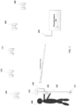
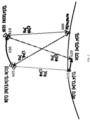
- FIG. 1 schematically illustrates a scenario using a GNSS rover with correction data for point surveying.
- a user 100 has a rover receiver (rover) 105 which is mounted on a range pole 110 or in some cases is a hand-held, or machine-mounted unit without a range pole.
- Rover 105 includes a GNSS antenna 115 and a communications antenna 120.
- Rover 105 receives at its GNSS antenna 115 the signals from GNSS satellites 125, 130, 135, 140, 145, etc.
- Rover 105 also receives at its communications antenna 120 correction data from a corrections source 150 via a communications link 155.
- the communications link is, for example, a radio link or mobile telephone link, or any other suitable means of conveying the correction data to the rover 105.
- the correction data can be of any suitable type for improving the positioning accuracy of rover 105, such as: differential base station data from a base station serving as corrections source 150, or virtual reference station data from a network of reference stations serving as corrections source 150 (WAAS is one example), or precise orbits and clocks data from a Precise Point Positioning (PPP) service such as that described in United States Provisional Application for Patent No. 61/277,184 filed 19 September 2009 (TNL A-2585P) and in International Publication Number WO 2011/034616 A2 dated 24 March 2011 (TNL A-2585PCT).
- PPP Precise Point Positioning
- the phase center of GNSS antenna 115 is determined and reduced for the height and orientation of the range pole 110 to the survey point 160.
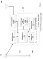
- FIG. 2 is a block diagram of a typical integrated receiver system 200 with GNSS antenna 115 and communications antenna 120.
- Receiver system 200 can serve as rover 105 or as a base station or reference station.
- Receiver system 200 includes a GNSS receiver 205, a computer system 210 and one or more communications links 215.
- Computer system 210 includes one or more processors 220, one or more data storage elements 225, program code 230 for controlling the processor(s) 220, and user input/output devices 235 which may include one or more output devices 240 such as a display or speaker or printer and one or more devices 245 for receiving user input such as a keyboard or touch pad or mouse or microphone.
- the program code 230 is adapted to perform novel functions in accordance with embodiments of the invention as described below.
- the integrated receiver system 200 can otherwise be of a conventional type suited for mounting on a range pole or for hand-held operation; some examples include the Trimble R8 GNSS, Trimble R7 GNSS, Trimble R6 GPS and Trimble 5700 surveying systems and the Trimble GPS Pathfinder Pro XRS system.
- FIG. 3 illustrates the error in the height component of synchronous RTK position estimates: 300, 301, 302, 303, ... 308, for epoch times 0.0, 1.0, 2.0, 3.0, ... 8.0 seconds respectively.
- the RTK position fixes: 300, 301, 305, & 306 are considered fixed i.e. have carrier phase ambiguities that are essentially resolved to integer values.
- the RTK position fixes at: 302, 303, 304, and 308, are considered float solutions, i.e., the carrier phase ambiguities cannot be resolved to integer values. Note that at time 7.0s, there is no RTK position solution.
- the precision (uncertainty) of each RTK position fix is represented by a vertical error bar.
- the fixed heights have better precision (less uncertainty) than the float heights.
- Autonomous (point position) solutions are produced by the rover GNSS receiver at say a 10Hz rate.
- the autonomous 1 Hz height estimates are: 310, 311, 312, 313, ... 318, corresponding to epoch times: 0.0, 1.0, 2.0, 3.0, ... 8.0s respectively.
- Autonomous position estimates generally have a precision of several decimeters up to several meters.
- FIG. 4 illustrates the timing of various events relevant to delta phase processing.
- Time axis 350 represents actual time, with values shown from 1.0s through to 3.0s.
- the rover GNSS receiver measurements are sampled and made available for processing a short time after the actual time.
- the rover measurements for epoch 1.0s are available at event 361.0; the rover measurements for epoch 1.2s are available at event 361.2; and so on, as shown on axis 360.
- Axis 370 corresponds to the time that correction data is received at the rover.
- the correction data must first be sampled by a real reference station, or a network of reference stations, before being sent and received by the rover, therefore there is an inherent latency in the received correction data.
- Event 371 corresponds to the receipt of correction data for epoch 1s;
- event 372 corresponds to the receipt of correction data for epoch 2s. Once the correction data is received it can be time-synchronized with rover data. Single-difference observations can be then be formed and a synchronous position solution computed.
- the rigorous satellite orbit and clock data is normally derived from a network of spatially distributed reference stations (e.g. a regional, or global network).
- the network GNSS observations must first be concentrated at a central facility, then processed and finally formatted and distributed to one or more rovers.
- the rigorous satellite orbit and clock data is often old by the time it reaches the rover(s).
- US 2009/0109090 A relates to position determination with reference data outage.
- the document describes position determination at a rover station on the basis of positioning signals from a plurality of positioning satellites. A position of the rover station is determined on the basis of the positioning signal and reference data received via a separate connection from a reference station.
- error data including satellite clock drifts is obtained and applied in the position determination process to eliminate positioning errors introduced by satellite clock drifts that cannot be compensated on the basis of the reference data due to the outage.
- the autonomous position of the rover is used as the linearization point for the delta position computations.
- the autonomous position of the rover is in error by several decimeters, up to several meters.
- Large errors in the linearization point leads to a proportional error in the output delta position estimates.
- the linearization errors accumulate with propagation time, therefore large correction data latency causes increased error growth in the delta position estimates.
- Delta phase is defined here as being the difference in carrier phase observed to a GNSS satellite over a specific time interval.
- GNSS carrier phase measurements observed by a receiver to a GNSS satellite have millimeter precision, however the measurements are affected by a number of biases. If carrier phase tracking is maintained, the delta phase measurements give a precise measure of the change in range (distance) between user and satellite over time.
- FIG. 5 illustrates an orbiting GNSS satellite at locations S(1), and S(2), denoted 405 and 410, at times t(1) and t(2) respectively.
- the user is located at positions U(1) and U(2), denoted 415 and 420, at times t(1) and t(2) respectively.
- the ranges from user to satellite at the two epochs are R(1) and R(2) respectively.
- the observed phase measurements ⁇ (1) and ⁇ (2) (given in meters) are free from errors and therefore are equal to the true ranges R(1) and R(2) respectively.
- ⁇ 1,2 def ⁇ 2 ⁇ ⁇ 1
- the satellite coordinates S(k) [ X(k), Y(k), Z(k) ] are known from a broadcast or rigorous satellite ephemeris.
- the user coordinates U(k) [ x(k), y(k), z(k) ] are the only unknown quantities in (3). If delta phase is observed to at least 3 satellites, the corresponding change in user location can be derived for the same time interval. In practice, a forth satellite must be observed in order to estimate the change in receiver clock over the delta phase time interval.
- the single receiver phase observation equation forms the basis of the delta phase observation equation and therefore is presented first.
- RHS right-hand side
- ⁇ k l f x ⁇ l , y ⁇ l , z ⁇ l , ⁇ ⁇ ⁇ k l + ⁇ f ⁇ x l ⁇ x l + ⁇ f ⁇ y l ⁇ y l + ⁇ f ⁇ z l ⁇ z l + ⁇ f ⁇ ⁇ k l ⁇ ⁇ k l
- the covariance matrix of the delta phase observations is required in the estimation process:
- Q ⁇ k l ⁇ ⁇ 1 k l 2 0 .. 0 0 ⁇ ⁇ 2 k l 2 .. 0 .. . . . 0 0 .. ⁇ ⁇ s k l 2
- Q ⁇ k l ⁇ 1 (sxs) observation weight matrix equal to the inverse measurement covariance matrix
- G ( k , l ) (4xs) gain matrix which relates a change in a measurement to a change in the estimated parameters.
- Rover position differences only provide an estimate of the relative trajectory of the rover over time.
- An anchor position absolute position
- the anchor position normally takes the form of a synchronous position, derived from processing single-difference rover and correction data in a filtering scheme that estimates rover position, phase ambiguities and other nuisance parameters.
- DGPS synchronous position
- inertial navigation systems etc.
- FIG. 6 describes the processing steps required to form a rover position difference between two epochs.
- Table 1 illustrates a time sequence of rover position differences buffered for high rate (say 5Hz) delta phase processing.
- Table 2 illustrates a time sequence of rover position differences buffered for low rate (1Hz) delta phase processing. Note that the time sequences are normally implemented as circular buffers, indexed with time.
- FIG. 7 illustrates a rover receiver at two consecutive epochs 615 and 620 respectively, tracking a single satellite.
- the satellite moves along orbit 630 and is located at 605, denoted S(1), at epoch 1, and 610, denoted S(2), at epoch 2.
- a stationary reference receiver 600 denoted B, tracks the same satellite as the rover.
- the location of the reference receiver is given in Cartesian coordinates as (x B ,y B ,z B ).
- Carrier phase measurements observed at the rover are given by ⁇ U (1) and ⁇ U (2), for epochs 1 and 2 respectively.
- the corresponding user-satellite ranges are given by R U (1) and R U (2) respectively.
- Carrier phase measurements observed at the reference are given by ⁇ B (1) and ⁇ B (2) for epochs 1 and 2 respectively; with corresponding user-satellite ranges: R B (1) and R B (2) respectively.
- ⁇ B (1) and ⁇ B (2) Carrier phase measurements observed at the reference are given by ⁇ B (1) and ⁇ B (2) for epochs 1 and 2 respectively; with corresponding user-satellite ranges: R B (1) and R B (2) respectively.
- the receiver clock drift parameter estimated is in fact the drift of the difference between rover and reference/correction clocks. In principle this does not imply any changes in the set-up of the computation of the position differences.
- the reference/correction data might not have all satellites available that are tracked at the rover. Also, they might occasionally have cycle slips at satellites or signals where there are no cycle slips at the rover.
- ⁇ ⁇ ( k , l ) is the single receiver clock drift and ⁇ ⁇ ⁇ ( k , l ) is the difference between rover and reference/correction data clock drift
- the first two observations relate to single-receiver differenced data and the last observation relates to single-differenced data.
- ⁇ ⁇ kl s 2 is the proper variance for a single-receiver observation as for the first two observations and ⁇ ⁇ ⁇ kl s 2 is the proper variance for a single-differenced observation as shown in (16).
- the latest GPS satellites broadcast coherent carriers on L1, L2 and L5 frequency bands.
- GLONASS satellites broadcast on two bands near GPS L1 and L2. All planned GNSS signal structures include at least two bands per satellite.
- Multi-frequency carrier phase measurements are often combined into various linear combinations with particular properties.
- the wide-lane GPS L1/L2 phase combination has an effective wavelength of 86cm making it useful for ambiguity resolution purposes.
- the iono-free phase combination is particularly useful for (essentially) removing the effect of ionospheric bias.
- the ionosphere presents a significant source of error in delta phase processing therefore the iono-free phase combination is particularly useful for delta phase positioning.
- the position calculations are normally performed at the rover receiver.
- the rover data is available within a fraction of a second after being sampled by the receiver.
- the correction data must be sampled, formatted, transmitted, received and decoded before it can be used for processing at the rover.
- the latency of the correction data is typically 1-60s, depending on the type of data link used.
- There are many high-precision applications where the location of the rover is required with very small latency. For example machine control where a cutting implement is driven to a design surface in real-time.
- Low latency RTK positioning can be achieved by combining single-receiver (rover) delta phase measurement processing with latent synchronous (base-rover) position solutions.
- FIG. 8 presents a block diagram illustrating the various components of a GNSS data processing scheme.
- the rover GNSS data, 650 is prepared at 654.
- the GNSS correction data 652 is prepared at step 656.
- the prepared rover and correction data are time matched and used to form single-difference GNSS observations 664, using the Single Difference Builder 658.
- the prepared rover data (654) is applied to the single-receiver delta phase processor 660, to produce a time sequence of rover position differences 662.
- the single-difference GNSS data 664 is used by the synchronous processor 666 in an estimation scheme (e.g., least squares estimator or Kalman filter) to estimate the rover position as well as carrier phase ambiguity and other nuisance parameters.
- an estimation scheme e.g., least squares estimator or Kalman filter
- the output of the synchronous processor 666 is synchronous positions 668.
- the single-difference GNSS data 664 is also used in the single-difference delta phase processor 670, to produce a time sequence of rover receiver (single-difference) position differences (672).
- the rover position difference time sequence (662), synchronous positions (668) and single-difference rover position difference time sequence 672, are optionally combined in Blender 674 to produce the reported position 676.
- Table 3 provides an illustration of the process used to construct reported position based on synchronous position and rover position difference estimates.
- the correction data latency is 1s and the data update rate is 5Hz.
- the first delta phase epoch occurs at 1.2s, when the two consecutive data epochs are available. Only rover position differences are available up until the first synchronized position fix is produced at epoch 2.0. Once synchronized position fixes are available, the reported position is constructed from the accumulation of rover position differences and the last synchronous fix. One Hz delta positions are used to propagate the synchronous positions across multiple seconds.
- Epoch Synchronous Position Rover Position Difference Reported Position 1.0 - - - 1.2 - ⁇ U (1.0, 1.2) - 1.4 - ⁇ U (1.2, 1.4) - 1.6 - ⁇ U (1.4, 1.6) - 1.8 - ⁇ U (1.6, 1.8) - 2.0 U (1.0) ⁇ U (1.8, 2.0) U (1.0) + ⁇ U (1.0, 2.0) 2.2 ⁇ U (2.0, 2.2) U (1.0) + ⁇ U (1.0, 2.0) + ⁇ U(2.0, 2.2) 2.4 ⁇ U(2.2, 2.4) U (1.0) + ⁇ U ( 1.0, 2.0) + ⁇ U (2.0, 2.2) + ⁇ U(2.2, 2.4) 2.6 ⁇ U (2.4, 2.6) U(1.0) + ⁇ U ( 1.0, 2.0) + ⁇ U (2.0, 2.2) + ⁇ U (2.2, 2.4) + ⁇ U (2.4, 2.6) U(1.0) + ⁇ U ( 1.0, 2.0)
- the synchronous positions have a latency of exactly 1s.
- an alternative approach would be to buffer carrier phase data at each epoch and then form delta phase measurements between the last synchronous epoch and the current time.
- the disadvantage of storing raw carrier phase observations is that significantly more data would need to be buffered compared with just rover position differences.
- the number of common satellites between the first and last delta phase epochs may be less than 4, even though 4 or more satellites were tracked throughout.
- the formal precision of the delta phase position solution can be derived directly from the least squares or Kalman filter process.
- the formal precision of the delta position estimates provided in (17) are for one delta-phase epoch time span i.e. epoch k to epoch 1.
- the variance for each delta phase measurement will be different for each satellite tracked at the same epoch. Also the delta phase measurement variances will vary for each satellite over time. Satellites that are low on the local horizon tend to be more affected by atmospheric errors and multipath, therefore satellites low on the horizon are assigned larger tropospheric, ionospheric and multipath variances. Furthermore, the signal strength is worse near the horizon and therefore the uncorrelated measurement noise is worse.
- Satellites with rigorous orbit and clock information can be processed with those satellites tracked at the same epoch that only have broadcast information. It is important to supply the appropriate a-priori measurement variances when mixing satellite observations derived from rigorous and broadcast sources.
- the low-latency reported position is given as the sum of a number of delta position epochs, combined with the last synchronous position (see the example in Table 4, extracted from Table 3). Table 4. Low-latency solution generation for epoch 4.0s, based on synchronous solution at 2.0s and delta positions.
- Epoch Synchronous Position Delta Phase Reported Position 4.0 U (3.0) Missing ⁇ U (3.8, 4.0) U (2.0) + ⁇ U (2.0, 3.0) + ⁇ U (3.0, 4.0)
- ⁇ ⁇ 2,4 2 ⁇ ⁇ 2 2 + ⁇ ⁇ 4 2 + ⁇ ⁇ T 2,4 2 + ⁇ ⁇ P 2,4 2 + ⁇ ⁇ 2,4 2 + ⁇ ⁇ I 2,4 2 + ⁇ ⁇ 2,4 2
- the over-estimation of the measurement variance in (21) is due to the inclusion of the uncorrelated noise term ⁇ ⁇ 3.0 2 twice on the right-hand side (RHS) of Equation (21).
- the uncorrelated noise terms are generally small compared with multipath errors and therefore one approach is to ignore the over-estimation problem and allow the reported position variances to be too pessimistic (too conservative).
- ⁇ ⁇ k l 2 ⁇ ⁇ k 2 + ⁇ ⁇ l 2 + ⁇ ⁇ ⁇ k l 2
- ⁇ ⁇ ⁇ k l 2 sum of time-wise variances for the epoch span k to l
- ⁇ ⁇ ⁇ k l 2 ⁇ ⁇ T k l 2 + ⁇ ⁇ P k l 2 + ⁇ ⁇ k l 2 + ⁇ ⁇ k l 2 + ⁇ ⁇ I k l 2 + ⁇ ⁇ k l 2
- Equation (18) is the standard formula for computing the delta phase position uncertainty. Whereas, just the time-wise errors are considered in the delta position uncertainty calculation in (24). Both Q x ⁇ ( k , l ) and Q x ⁇ ⁇ ( k , l ) are computed and stored for each delta phase time span.
- the error growth of single-receiver delta phase positioning can be bounded with the aid of rigorous satellite orbit and clock information.
- MEO satellite trajectories are generally smooth, however fluctuations in solar radiation pressure and eclipsing events can cause fluctuations in the satellite orbit with respect to the broadcast antenna location.
- Satellite clock information needs to be updated every few seconds to ensure that error growth in single-receiver delta position do not exceed a few millimeters.
- the International GNSS Service generates rigorous network predicted orbits based on GNSS data from globally distributed tracking stations.
- the IGS refers to their rigorous-network predicted orbits as Predicted Precise Orbits. Their Predicted Precise Orbits are made available for download via the Internet (see Kouba, A Guide to Using International GPS Service (IGS) Products. Geodetic Survey Division, Natural Resources Canada, February 2003, http://igscb.jpl.nasa.gov/components/prods.html ).
- the IGS Predicted Precise orbits are updated 4 times per day and have a quoted accuracy of 5cm. Independent testing has shown that occasionally several meters of error may occur in the IGS orbit products.
- GNSS satellite clocks have very stable behavior, however certain events have been observed on several GPS satellites between 2009-2010. Those events show a satellite clock noise which is about one magnitude larger than usual. To avoid using clock predictions during such an event, clock predictability numbers are computed and sent to the rover.
- a Kalman filtering scheme can be applied to the models defined by Equations (26), (27) and (28), with one filter per satellite.
- the predicted clock error T ⁇ s ( k ) for each satellite is used in the right-hand side (RHS) of (4) to correct the delta phase measurements.
- the predictability numbers p 120 s k for good satellites are typically below 0.25m, for a regular satellite it is between 0.25m and 0.5m, for a bad satellite it's between 0.5m and 0.75m. If the number is above 0.75m the satellite should not be used for predictions. Most of the GPS and nearly all GLONASS satellites have numbers below 0.25m.
- Satellite clock quality indicators can be produced either by the network software or by the rover(s).
- the clock quality indicators are used in the apriori noise model of the rover receiver delta phase processor. Satellites with highly predictable clocks are therefore given more weight (smaller variance ⁇ ⁇ T k l 2 ) than satellites with poor predictability. Furthermore, satellites that have only orbit / clock correction parameters from the broadcast navigation data are given less weight (larger variance) than those satellites with rigorous orbit / clock corrections.
- Table 5 provides a summary of the systematic errors affecting delta phase observations.
- Table 5 Characterization of errors affecting delta phase observations.
- Parameter Description Characteristic of error ⁇ T ( k , l ) Satellite clock drift Dependent on the stability of the satellite clock. Satellite atomic frequency standards have long term stabilities of ⁇ 10 -12 . The satellite clock drift rate must be scaled by the speed of light to determine the impact on the delta phase measurements. The unmodelled satellite clock drift rate causes several millimeters / second error in delta phase positioning.
- Rigorous orbits are good to around 2-5cm. Satellite orbit errors cause a drift in the delta phase position estimates which is dependent on the magnitude of the satellite position error. ⁇ ( k , l ) Tropospheric bias
- the tropospheric bias term refers to the unmodelled part of the tropospheric error rate. Generally the tropospheric bias changes slowly (over tens of minutes), however passing weather fronts cause a faster rate of change of say 10-50mm / minute.
- Ionospheric bias The rate of change of the unmodelled ionospheric bias is on the order of say 5-20mm/s for low elevation satellites and less for high-elevation satellites (under stable ionospheric conditions).
- the iono bias is a significant error source for delta phase processing.
- the ionospheric bias can be obviated using iono-free delta phase processing.
- ⁇ ( k , l ) Multipath bias The rate of change of the carrier phase multipath is typically 5-20mm / minute for low-elevation satellites and much less for high elevation satellites (which are generally less affected by signal reflections).
- Multipath bias is cyclic in nature and is generally ⁇ 5cm in magnitude.
- Table 6 provides a summary of the magnitude of errors affecting single-receiver and single-difference delta phase observations.
- all satellite and atmospheric errors directly impact on rover position difference estimates.
- With single-difference delta phase processing the closer the separation of base and rover the less the impact of orbit and atmospheric errors on the estimated rover position difference.
- Satellite orbit error broadcast orbit broadcast orbit : 1.0e-3 to 3.0c-3 m/s B*1.0e-3 to B*3.0e-3 m/s rigorous network predicted orbit: rigorous network predicted orbit: 3.0e-3 to 5.0e-4 m/s B*3.0e-3 to B*5.0e-4 m/s rigorous orbit: rigorous orbit: 5.0e-5 to 7.5e-5 m/s B*5.0e-5 to B*7.5e-5 m/s Tropospheric bias 5.0e-6 to 1.0e-3 m/s B*5.0e-6 to B*1.0e-3 m/s Ionospheric bias 1.0e-3 to 0.02 m/s B*0.001 to B*0.02 m/s Nil when using iono-free phase Nil when using iono-free phase Multipath bias Up to
- Table 7 summarizes the errors affecting single-receiver delta phase processing based on rigorous orbit / clock correction data. Note that the satellite clock drift and orbit errors only accumulate until the next satellite clock/orbit correction message is received. Also note that the ionospheric bias is normally zero since iono-free delta phase processing is used. The remaining errors are due to unmodelled tropospheric bias and carrier phase multipath, both of which change relatively slowly over time. Table 7. Magnitude of typical errors affecting delta phase measurements for a single satellite /receiver aided with rigorous satellite orbit and clock information.
- Error Source Magnitude of Error Source Satellite clock drift ⁇ 1.0e-4 m/s Satellite orbit error ⁇ 5.0e-5 m/s Tropospheric bias 5.0e-6 to 1.0e-3 m/s Ionospheric bias Nil for iono-free phase Multipath bias Up to 0.0005 m/s
- the computation of rover position difference from delta phase measurements involves the use of approximate rover coordinates at the first and current epochs as described above in steps 1-7 of Rover Position Difference Processing Steps.
- the true rover positions at the first and second epoch are 710 and 715, denoted U(1) and U(2) respectively.
- the corresponding true ranges for the first and second epoch are R(1) and R(2) respectively.
- the true user position is not known, but rather approximate user positions arc obtained from, c.g., autonomous or differential GNSS solutions.
- the approximate user positions at the first and second epoch are 720 and 725, denoted: U'(l) [x'(l),y'(l),z'(l)] and U'(2) [x'(2),y'(2),z'(2)] respectively.
- the ranges computed from the biased user positions are denoted R'(1) and R'(2) respectively. Errors in the computed ranges lead to errors in the rover position difference estimates. In effect a strain is produced in the computed range, which tends to increase over time as satellites move.
- the proposed method involves computing the rover position differences as soon as the rover data becomes available.
- the derived rover position differences are subsequently corrected for a change in the initial position as soon as a precise anchor position is made available.
- a l T Q ⁇ k l ⁇ 1 A l ⁇ 1 A l T Q ⁇ k l ⁇ 1 in (32) is called the measurement gain matrix [ G (k,l) ] and is available in the original estimation process [see (12)].
- the second term [ A ( k ) - A ( l )] reflects the geometry change between both epochs mainly caused by motion of the satellites and has to be computed in parallel to the initial delta-position estimation using the approximate initial position.
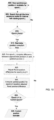
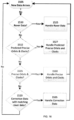
- FIG. 10 contains a flowchart which summarizes the procedure used to adjust delta position estimates for errors in initial coordinates.
- the following example illustrates the position adjustment process: At 800, a synchronous position becomes available for epoch 1.0s (i.e. we have ⁇ (1.0) ).
- the synchronous (anchor) position is known to be accurate to say a few centimeters in a global sense.
- the time sequence (rover delta position difference) buffer is scanned in steps 805 and 810 until a matching interval is found with starting time 1.0s and end time 2.0s.
- step 835 A test is made at step 835 to see if the adjustment process is complete for all epochs.
- the current time is 3.0s, hence steps 3-6 must be repeated for the time interval 2.0 - 3.0s.
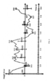
- FIG. 11 depicts the adjustment for initial position errors.
- just the height component of a stationary rover is considered.
- hollow circles correspond to autonomous height estimates at each measurement epoch (920).
- Grey lines indicate rover position difference height estimates. Note that the further the initial height is away from the correct height, the larger the error in the rover position difference height estimate. Also note that the rover position difference height estimates are affected in this example by both the systematic effect of initial height error, plus the random delta phase measurement errors.
- the trace in sub-graph 905 is obtained by first shifting the rover position difference height estimate for t(1.0,1.1) to join with the synchronous position height at t(1.0). Next the rover position difference height estimate t(1.1-1.2) is linked to the previous position at t(1.1), and so on until the next synchronous position height is available, in this case at t(2.0).
- the synchronous position height estimates contain small errors and therefore discontinuities exist when linking delta positions with synchronous positions.
- rover position difference heights are linked to the synchronous position estimates and adjusted for errors in the initial position estimates.
- the rover position difference adjustment process outlined above was presented based on a low-latency, single-receiver delta phase-based positioning example. It should be stressed that the adjustment process is valid for all types of single-receiver and single-difference delta phase positioning.
- Single-receiver rover position difference estimates are normally generated at say 5, 10 or 20Hz. Typically the rover position difference estimates form a smooth trajectory. Small jumps sometimes occur with changes in satellites geometry, i.e. new satellites entering the solution, or satellites being lost. As implied by the name, rover position difference estimates only provide relative changes in user location over time. The absolute position of the user is required at an epoch to be able to anchor the rover position differences. Synchronous position estimates derived from a position + ambiguity processor are normally used in conjunction with delta phase processing to produce low-latency position estimates.
- Measurement errors lead to variations in the synchronous position estimates, which in turn leads to discontinuities in the reported position trajectory.
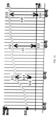
- FIG. 12 illustrates a 10Hz rover position difference trajectory 1005, from time 1.0 to 4.0s. Just the height component is shown. Synchronous position solutions are generated at 1Hz and are illustrated as solid black circles 1010, 1020, 1030 & 1040.
- the rover position difference trajectory 1005 is first adjusted to the synchronous position 1010, at 1.0s. When the next synchronous position is available for 2.0s, 1020, the rover position difference trajectory is shifted by 1045, to 1060. Trajectory 1060 is again shifted based on the synchronous position 1030, at 3.0s, to form 1070. This adjustment process is repeated at 4.0s, and so on.
- a step in the rover position difference trajectory occurs for each synchronous position adjustment. Note that the magnitude of the stepping effect has been exaggerated for the purposes of this example.
- FIG. 13 illustrates a 4s rover position difference trajectory (1105). Synchronous positions are obtained at times 1,2,3 & 4s, denoted 1110, 1120, 1130 & 1140 respectively. Comparisons can be made between the rover position difference estimates at 1Hz epochs (1115, 1125 & 1135) with the corresponding synchronous position estimates (1120, 1130 & 1140), thus leading to the differences 1145, 1150 and 1155, respectively. Rather than introducing abrupt steps in the reported position trajectory, it is possible to blend the rover position difference trajectory with the synchronous positions.
- the blending process involves the following steps:
- a buffer of the last n synchronous position fixes is maintained, as well as a buffer of the last n corresponding rover position difference estimates.
- Table 8 provides an example of the position buffering and blending process for the example given in FIG. 13
- the synchronous positions are shown in column 2 as: U (1.0), U (2.0), U (3.0) & U (4.0).
- Delta phase processing yields rover position differences: U (1.0,2.0), U (2.0,3.0), U (3.0,4.0) as shown in column 3.
- Multiple estimates of the position at the anchor epochs can be obtained using the previous synchronous solutions and the buffered delta positions as shown in column 4.
- Blending factors ⁇ (a,b) are used to weight the synchronous solution and propagated synchronous positions at the anchor epoch.
- weighting factors [ ⁇ (a,b) ] determines the characteristics of the blended solution. Normally the most recent synchronous position is given the most weight, while the oldest position the least weight. A linear, exponential or other suitable, weighting scheme can be used.
- Table 8 shows that the last 4 seconds of propagated synchronous solutions are used in the blended anchor position.
- the number of solutions considered in the blending process is limited in order to minimize the computation load and buffer storage requirements. Furthermore, in practice, only 2-10s are needed to effectively blend the solutions.
- n linear a b ⁇ ⁇ b ⁇ a ⁇ for b ⁇ a ⁇ ⁇ 0 else
- Table 10 An illustration of the precision-based blending scheme is presented in Table 10. Just the x-coordinate is included in the example. However the approach used for the y- and z-coordinate is analogous to that used for the x-coordinate. Table 10. Precision-based blending factors for example in Table 6. The x-coordinate blending factors are computed based on the precisions of the x-coordinate shown in column 3.
- Precise Single-receiver delta phase processing with rigorous satellite and clock information
- Precise single-receiver Delta Phase
- Predicted Precise Delta Phase When the rigorous satellite clock information is predicted in time, this is termed Predicted Precise Delta Phase.
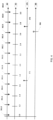
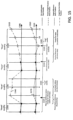
- FIG. 14 provides an illustration of the relative uncertainties of various solutions types over time assuming all solution types use the same satellite geometry.
- the axis 1205 corresponds to fixed- quality synchronous solutions, with each position 1230, identified with solid black dots.
- the uncertainty of the positions is represented by error bars 1235.
- the float-quality synchronous positions on axis 1210 have larger uncertainty than the fixed- quality synchronous solutions, as evidenced by the longer error bars 1245.
- Each float-quality synchronous position, 1240 shows larger variations about the zero axis, 1210.
- the error growth of single-difference rover position differences is represented by the region between the dashed lines (1255) on axis 1215.
- Each single-difference rover position estimate 1250 is shown by a grey circle surrounded by a black ring.
- the precise single-receiver rover position difference positions are presented on axis 1220. Each position fix is marked by a black ring (1260). The error growth of the precise rover position difference estimates is shown as the region 1265, assuming that the propagation time starts at first epoch and accumulates thereafter.
- the predicted-precise single-receiver rover position differences are presented on axis 1222. Each position fix is marked by a dark grey circle surrounded by a black ring (1262). The error growth of the predicted-precise rover position difference estimates is shown as the region 1267.
- the single-receiver rover position differences (broadcast orbits and clocks) is shown on axis 1225, with each position fix marked by a grey ring.
- the error growth of the single-receiver rover position differences is defined by the region 1275.
- the time-wise error growth of single-difference rover position difference is lower than that of the precise (single-receiver) rover position difference; which is lower than the predicted-precise rover position difference; which is lower than the single-receiver rover position difference (broadcast orbits and clocks).
- Single-difference processing requires reference and rover receivers to be tracking common satellites. In many circumstances, the number of single-difference satellites may be less than the number of rover (single-) receiver satellites. In which case, the single-difference rover position difference error growth may be worse than that of single-receiver rover position differences.
- FIG. 15 presents timeline views of positions (height component only) derived from prior art and new techniques.
- the upper axis 1305, refers to prior-art positioning methods, while the lower axis, 1310, to new techniques.
- the position trace for axis 1305 is denoted 1315; for axis 1310, the position trace is denoted 1320.
- precise single-receiver rover position difference processing is used at epoch 3 (denoted 1370) to propagate the fixed quality synchronous solution from epoch 2 to epoch 3.
- Single-difference rover position difference processing is then used at epochs 4 - 6, to produce high-quality position estimates until regular synchronous fixed quality solutions are regained at epoch 6.
- Precise single-receiver rover position difference processing is again used between epochs 7-9, while the reference receiver data is unavailable.
- precise-single receiver rover position difference processing and single-difference rover position differences enables fixed quality solutions to be provided (segment 1360).
- the rigorous clock/orbit corrections are lost at event 1335, around epoch 9, after which only single-receiver (broadcast orbits and clocks) rover position difference processing is used to deliver solutions with float quality (segment 1365).
- FIG. 16 presents a flowchart that explains the handling of data at the rover.
- new data arrives at 1505, it is tested at 1510 to see if it is rover data. If so, rover data handling occurs at 1525.
- Predicted Precise orbit and clock information when available (see test 1512) is handled at 1527.
- Test 1515 checks for the presence of Precise Orbit and Clock information. When present, the Precise Orbits and Clocks are handled at 1530.
- the input data is tested at 1520 to see if it is from the reference and can be single-differenced. If so, the single-difference data is handled at 1535.
- FIG. 17 shows an expanded view of flowchart 1500.
- rover data When rover data is received, it is used to form a rover position difference solution between the current and previous epoch (1605).
- the rover position difference estimate is then buffered at step 1610, and optionally used to generate a low-latency position estimate at 1612.
- the rigorous predicted satellite clock/orbit models are updated at 1613.
- the rigorous predicted clock/orbit information is optionally used at 1614 to update the rover position difference for the current data epoch.
- the rigorous predicted orbit information is used to update the time sequence of rover position difference estimates.
- the best rover position difference time sequence is generated at 1616 based on the predicted precise rover position difference time sequence and existing broadcast rover position difference time sequence.
- the best rover position difference from 1616 is used to replace the predicted rover position difference time sequence at 1617.
- the rigorous satellite clock/orbit models are updated at 1620, as soon as rigorous orbit and clock information is received for one or more satellites.
- the rigorous clock models enable the rover position difference time sequence derived from broadcast clocks to be optionally refined (1625) and stored.
- the rigorous orbit and clock information is used to form a precise rover position difference estimate for the current and previous epochs at 1630.
- the best rover position difference time sequence is produced based on the existing precise position sequence.
- the predicted rover position difference time sequence is replaced by the rover position difference time sequence with the smallest error.
- synchronous reference data When synchronous reference data are received, they are used to compute single-difference delta phase measurements and rover position difference estimates at 1645.
- the rover position difference time sequence with the smallest uncertainty is generated at step 1650, and used to replace the existing rover position difference time sequence at 1655.
- a synchronous position result is produced at 1660, using the latest single-difference GNSS measurements.
- the best (smallest uncertainty) synchronous position solution is derived from the latest synchronous position result, and the single-difference rover position difference time sequence in step 1665. If for example the synchronous position result is float quality, then often the single-difference rover position difference time sequence that was propagated from the last fixed quality solution will be the best (smallest uncertainty).
- all of the single-difference rover position differences up to the reference data time tag are replaced with the new synchronous position solution.
- an optional report of the synchronous position is provided which will be latent with respect to the current time.
- the components, process steps and/or data structures may be implemented using various types of operating systems (OS), computer platforms, firmware, computer programs, computer languages and/or general-purpose machines. Portions of the methods can be run as a programmed process running on processing circuitry.
- the processing circuitry can take the form of numerous combinations of processors and operating systems, or a stand-alone device.
- the processes can be implemented as instructions executed by such hardware, by hardware alone, or by any combination thereof.
- the software may be stored on a program storage device readable by a machine.
- Computational elements, such as filters and banks of filters can be readily implemented using an object-oriented programming language such that each required filter is instantiated as needed.
- FPLDs field programmable logic devices
- FPGAs field programmable gate arrays
- CPLDs complex programmable logic devices
- ASICs application specific integrated circuits
- the methods may be implemented in part on a data processing computer such as a personal computer, workstation computer, mainframe computer, or high-performance server running an operating system such as a version of Microsoft Windows, or various versons of the Unix operating system such as Linux available from a number of vendors.
- the methods may also be implemented on a multiple-processor system, or in a computing environment including various peripherals such as input devices, output devices, displays, pointing devices, memories, storage devices, media interfaces for transferring data to and from the processor(s), and the like.
- a computer system or computing environment may be networked locally, or over the Internet.
- any of the above-described methods and their embodiments may be implemented in part by means of a computer program.
- the computer program may be loaded on an apparatus as described above. Therefore, the invention also relates to a computer program, which, when carried out on an apparatus performs portions of any one of the above above-described methods and their embodiments.
- the invention also relates to a computer-readable medium or a computer-program product including the above-mentioned computer program.
- the computer-readable medium or computer-program product may for instance be a magnetic tape, an optical memory disk, a magnetic disk, a magneto-optical disk, a CD ROM, a DVD, a CD, a flash memory unit or the like, wherein the computer program is permanently or temporarily stored.
- the invention also relates to a computer-readable medium (or to a computer-program product) having computer-executable instructions for carrying out any one of the methods of the invention.
- the invention also relates to a firmware update adapted to be installed on apparatus already in the field, i.e. a computer program which is delivered to the field as a computer program product. This applies to each of the above-described methods and apparatuses.
Landscapes
- Engineering & Computer Science (AREA)
- Radar, Positioning & Navigation (AREA)
- Remote Sensing (AREA)
- Computer Networks & Wireless Communication (AREA)
- Physics & Mathematics (AREA)
- General Physics & Mathematics (AREA)
- Position Fixing By Use Of Radio Waves (AREA)
Claims (4)
- Positionierungsverfahren, das durch eine Positionierungsvorrichtung ausgeführt wird, das Positionierungsverfahren umfassenda. Erhalten einer angenäherten Rover-Ankerposition (U' (1,0)) für eine erste Epoche aus einer autonomen Positionslösung oder einer differentiellen Positionslösung des Rovers,b. Verwenden der angenäherten Rover-Ankerposition (U' (1,0)), um eine Rover-Positionsdifferenz (δÛ(1.0,2.0)) aus Deltaphasenmessungen an dem Rover zwischen der ersten Epoche und einer nachfolgenden Epoche zu bestimmen,b1. wobei die angenäherte Rover-Ankerposition einen Anfangsfehler enthält, wobei die Rover-Positionsdifferenz (δÛ(1,0, 2,0)) für die nachfolgende Epoche einen jeweiligen Teilfehler basierend auf dem Anfangsfehler enthält,c. Erhalten (800) einer verbesserten Rover-Ankerposition für die erste Epoche, wobei die verbesserte Rover-Ankerposition eine synchrone Rover-Ankerposition (Ü(1,0)) ist, die für die erste Epoche verfügbar wird, wobei die synchrone Ankerposition auf Zentimeter-Ebene genau ist und die angenäherte Rover-Ankerposition im Allgemeinen auf Meter-Ebene genau ist, danachd. Ableiten (825) einer angepassten Rover-Positionsdifferenz (δ(1,0, 2,0)) unter Verwendung der bestimmten Rover-Positionsdifferenz (δÛ(1,0, 2,0)) für die nachfolgende Epoche,
 d1. wobei das Ableiten der angepassten Rover-Positionsdifferenz (δ(1,0, 2,0)) für die nachfolgende Epoche Addieren eines Korrekturterms (γ(1,0, 2,0)), der sich auf den Anfangsfehler bezieht, zu der bestimmten Rover-Positionsdifferenz (δÛ(1,0, 2,0)) umfasst, wobei der Anfangsfehler die Differenz zwischen der verbesserten Rover-Ankerposition (Ü(1,0)) und der angenäherten Rover-Ankerposition (U' (1,0)) ist; unde. Ableiten (830) einer Rover-Position (Ü(2,0)) für die nachfolgende Epoche aus der verbesserten Rover-Ankerposition (Ü(1,0)) für die erste Epoche und der angepassten Rover-Positionsdifferenz (δ(1,0, 2,0) für die nachfolgende Epoche,e1. wobei das Ableiten der Rover-Position ((Ü(2,0)) für die nachfolgende Epoche Addieren der angepassten Rover-Positionsdifferenz (δ(1,0, 2,0)) für die nachfolgende Epoche zu der verbesserten Rover-Ankerposition (Ü(1,0)) für die erste Epoche umfasst.
- Positionierungsvorrichtung, die einen Prozessor (220) und Speicher (225) und einen Satz von Anweisungen (230) umfasst, die dem Prozessor (220) Folgendes ermöglichen:a. Erhalten einer angenäherten Rover-Ankerposition (U'(1,0)) für eine erste Epoche aus einer autonomen Positionslösung oder einer differentiellen Positionslösung des Rovers,b. Verwenden der angenäherten Rover-Ankerposition (U' (1,0)), um eine Rover-Positionsdifferenz (δÛ(1,0, 2,0)) aus Deltaphasenmessungen an dem Rover zwischen der ersten Epoche und einer nachfolgenden Epoche zu bestimmen,b1. wobei die angenäherte Rover-Ankerposition einen Anfangsfehler enthält, wobei die Rover-Positionsdifferenz (δÛ(1,0, 2,0)) für die nachfolgende Epoche einen jeweiligen Teilfehler basierend auf dem Anfangsfehler enthält,c. Erhalten (800) einer verbesserten Rover-Ankerposition für die erste Epoche, wobei die verbesserte Rover-Ankerposition eine synchrone Rover-Ankerposition (Ü(1,0)) ist, die für die erste Epoche verfügbar wird, wobei die synchrone Ankerposition auf Zentimeter-Ebene genau ist und die angenäherte Rover-Ankerposition im Allgemeinen auf Meter-Ebene genau ist, danachd. Ableiten (825) einer angepassten Rover-Positionsdifferenz (δ(1,0, 2,0)) unter Verwendung der bestimmten Rover-Positionsdifferenz (δÛ(1,0, 2,0)) für die nachfolgende Epoche,d1. wobei die Ableitung der angepassten Rover-Positionsdifferenz (δ(1,0, 2,0)) für die nachfolgende Epoche Addieren eines Korrekturterms (γ(1,0, 2,0)), der sich auf den Anfangsfehler bezieht, zu der bestimmten Rover-Positionsdifferenz (δÛ(1,0, 2,0)) umfasst, wobei der Anfangsfehler die Differenz zwischen der verbesserten Rover-Ankerposition (Ü(1,0)) und der angenäherten Rover-Ankerposition (U' (1,0)) ist; unde. Ableiten (830) einer Rover-Position (Ü(2,0)) für die nachfolgende Epoche aus der verbesserten Rover-Ankerposition (Ü(1,0)) für die erste Epoche und der angepassten Rover-Positionsdifferenz (δ(1,0, 2,0) für die nachfolgende Epoche,e1. wobei die Ableitung der Rover-Position ((Ü(2,0)) für die nachfolgende Epoche Addieren der angepassten Rover-Positionsdifferenz (δ(1,0, 2,0)) für die nachfolgende Epoche zu der verbesserten Rover-Ankerposition ((1,0)) für die erste Epoche umfasst.

- Computerprogrammprodukt, das ein greifbares computerlesbares Medium umfasst, das Anweisungen zum Veranlassen einer Vorrichtung, das Verfahren nach Anspruch 1 durchzuführen, verkörpert.
- Computerprogramm, das Anweisungen zum Veranlassen einer Vorrichtung, das Verfahren nach Anspruch 1 durchzuführen, umfasst.
Applications Claiming Priority (3)
| Application Number | Priority Date | Filing Date | Title |
|---|---|---|---|
| US201161466050P | 2011-03-22 | 2011-03-22 | |
| PCT/US2012/029694 WO2012151006A1 (en) | 2011-03-22 | 2012-03-19 | Gnss signal processing with delta phase |
| EP12779870.0A EP2689267A4 (de) | 2011-03-22 | 2012-03-19 | Gnss-signalverarbeitung mit einer deltaphase |
Related Parent Applications (1)
| Application Number | Title | Priority Date | Filing Date |
|---|---|---|---|
| EP12779870.0A Division EP2689267A4 (de) | 2011-03-22 | 2012-03-19 | Gnss-signalverarbeitung mit einer deltaphase |
Publications (2)
| Publication Number | Publication Date |
|---|---|
| EP3206050A1 EP3206050A1 (de) | 2017-08-16 |
| EP3206050B1 true EP3206050B1 (de) | 2025-01-08 |
Family
ID=47107991
Family Applications (2)
| Application Number | Title | Priority Date | Filing Date |
|---|---|---|---|
| EP17162542.9A Active EP3206050B1 (de) | 2011-03-22 | 2012-03-19 | Gnss-signal-verarbeitung mit deltaphase |
| EP12779870.0A Withdrawn EP2689267A4 (de) | 2011-03-22 | 2012-03-19 | Gnss-signalverarbeitung mit einer deltaphase |
Family Applications After (1)
| Application Number | Title | Priority Date | Filing Date |
|---|---|---|---|
| EP12779870.0A Withdrawn EP2689267A4 (de) | 2011-03-22 | 2012-03-19 | Gnss-signalverarbeitung mit einer deltaphase |
Country Status (4)
| Country | Link |
|---|---|
| US (4) | US9562975B2 (de) |
| EP (2) | EP3206050B1 (de) |
| CN (1) | CN103502843B (de) |
| WO (1) | WO2012151006A1 (de) |
Families Citing this family (104)
| Publication number | Priority date | Publication date | Assignee | Title |
|---|---|---|---|---|
| CN102171583B (zh) | 2008-10-06 | 2015-02-18 | 天宝导航有限公司 | 位置估计方法和设备 |
| DE112010000673B4 (de) | 2009-02-22 | 2022-11-10 | Trimble Navigation Ltd. | Verfahren und Geräte zur GNSS-Signalverarbeitung mit ionosphärischen Filtern |
| DE112010000674B4 (de) | 2009-02-22 | 2024-03-07 | Trimble Navigation Limited | Verfahren und Vorrichtung zur GNSS-Vermessung |
| CN102414577B (zh) | 2009-05-02 | 2014-04-16 | 天宝导航有限公司 | Gnss信号处理方法和设备 |
| US8847820B2 (en) | 2009-09-19 | 2014-09-30 | Trimble Navigation Limited | GNSS signal processing to estimate orbits |
| DE112011100528T5 (de) | 2010-02-14 | 2012-12-06 | Trimble Navigation Limited | GNSS-Signalverarbeitungmit regionaler Augmentationsnachricht |
| US20120119944A1 (en) | 2010-05-30 | 2012-05-17 | Trimble Navigation Limited | Gnss atmospheric estimation with ambiguity fixing |
| US9170335B2 (en) | 2011-02-14 | 2015-10-27 | Trimble Navigation Limited | GNSS signal processing with ionosphere model for synthetic reference data |
| US9116231B2 (en) | 2011-03-11 | 2015-08-25 | Trimble Navigation Limited | Indicating quality of GNSS position fixes |
| CN103430046B (zh) | 2011-03-22 | 2015-08-12 | 天宝导航有限公司 | 用于重新收敛的利用已知定位的gnss信号处理 |
| EP3206050B1 (de) | 2011-03-22 | 2025-01-08 | Trimble Inc. | Gnss-signal-verarbeitung mit deltaphase |
| US9645245B2 (en) | 2011-09-16 | 2017-05-09 | Trimble Inc. | GNSS signal processing methods and apparatus |
| US9590411B2 (en) | 2011-12-15 | 2017-03-07 | Schweitzer Engineering Laboratories, Inc. | Systems and methods for time synchronization of IEDs via radio link |
| US9709680B2 (en) | 2012-09-08 | 2017-07-18 | Schweitzer Engineering Laboratories, Inc. | Quality of precision time sources |
| US9671501B2 (en) | 2012-09-26 | 2017-06-06 | Trimble Inc. | Global navigation satellite systems (GNSS) positioning using precise satellite data |
| US9520860B2 (en) | 2012-10-19 | 2016-12-13 | Schweitzer Engineering Laboratories, Inc. | Time distribution switch |
| ES2547028R1 (es) | 2012-10-19 | 2015-12-02 | Schweitzer Engineering Laboratories, Inc. | Dispositivo de distribución de tiempo con antena multibanda |
| US9599719B2 (en) | 2012-10-19 | 2017-03-21 | Schweitzer Engineering Laboratories, Inc. | Detection of manipulated satellite time signals |
| US9400330B2 (en) | 2012-10-19 | 2016-07-26 | Schweitzer Engineering Laboratories, Inc. | Manipulation resilient time distribution network |
| US9405015B2 (en) | 2012-12-18 | 2016-08-02 | Subcarrier Systems Corporation | Method and apparatus for modeling of GNSS pseudorange measurements for interpolation, extrapolation, reduction of measurement errors, and data compression |
| US9759816B2 (en) | 2013-01-11 | 2017-09-12 | Schweitzer Engineering Laboratories, Inc. | Multi-constellation GNSS integrity check for detection of time signal manipulation |
| US9709682B2 (en) | 2013-05-06 | 2017-07-18 | Schweitzer Engineering Laboratories, Inc. | Multi-constellation GNSS integrity check for detection of time signal manipulation |
| CA2892282A1 (en) * | 2013-01-11 | 2014-10-02 | Schweitzer Engineering Laboratories, Inc. | Multi-constellation gnss integrity check for detection of time signal manipulation |
| US9250327B2 (en) | 2013-03-05 | 2016-02-02 | Subcarrier Systems Corporation | Method and apparatus for reducing satellite position message payload by adaptive data compression techniques |
| US9083503B2 (en) | 2013-05-02 | 2015-07-14 | Schweitzer Engineering Laboratories, Inc. | Synchronized clock event report |
| JP6302630B2 (ja) * | 2013-06-14 | 2018-03-28 | 株式会社トプコン | Rtk測量作業に用いる準備システム |
| US9319100B2 (en) * | 2013-08-12 | 2016-04-19 | Schweitzer Engineering Laboratories, Inc. | Delay compensation for variable cable length |
| US10018728B2 (en) | 2013-12-17 | 2018-07-10 | Trimble Inc. | Navigation satellite system positioning with enhanced satellite-specific correction information |
| US9270442B2 (en) | 2014-04-29 | 2016-02-23 | Schweitzer Engineering Laboratories, Inc. | Time signal propagation delay correction |
| WO2015183262A1 (en) * | 2014-05-28 | 2015-12-03 | Subcarrier Systems Corp. | Method and apparatus for reducing satellite position message payload by adaptive data compression techniques |
| US9425652B2 (en) | 2014-06-16 | 2016-08-23 | Schweitzer Engineering Laboratories, Inc. | Adaptive holdover timing error estimation and correction |
| US9945955B2 (en) * | 2014-09-03 | 2018-04-17 | Glacial Ridge Technologies, LLC | Device for inputting RTK correction data to a GPS |
| NL2013471B1 (en) * | 2014-09-15 | 2016-09-28 | Fugro N V | Method and system for dynamic-to-dynamic precise relative positioning using Global Navigation Satellite Systems. |
| US9813173B2 (en) | 2014-10-06 | 2017-11-07 | Schweitzer Engineering Laboratories, Inc. | Time signal verification and distribution |
| US10234566B2 (en) * | 2015-02-11 | 2019-03-19 | Trimble Inc. | Fast GNSS receiver convergence by relative positioning |
| US10234565B2 (en) * | 2015-02-11 | 2019-03-19 | Trimble Inc. | Global navigation satellite system receiver convergence selection |
| US10241213B2 (en) * | 2015-02-11 | 2019-03-26 | Trimble Inc. | Timer initiated convergence of a GNSS receiver |
| WO2016163910A1 (en) * | 2015-04-09 | 2016-10-13 | Limited Liability Company "Topcon Positioning Systems" | Reducing time and increasing reliability of ambiguity resolution in gnss |
| WO2016201347A1 (en) * | 2015-06-10 | 2016-12-15 | Hemisphere Gnss Inc. | Translation of kinematic gnss data to an alternate location |
| FR3038067B1 (fr) * | 2015-06-24 | 2017-08-18 | Inst Mines-Telecom | Procede de localisation d'un recepteur au sein d'un systeme de positionnement |
| US12210107B2 (en) | 2015-06-29 | 2025-01-28 | Deere & Company | Satellite navigation receiver for relative positioning with bias estimation |
| US10605926B2 (en) * | 2015-06-29 | 2020-03-31 | Deere & Company | Satellite navigation receiver and method for switching between real-time kinematic mode and relative positioning mode |
| US11175414B2 (en) * | 2015-06-29 | 2021-11-16 | Deere & Company | Satellite navigation receiver for relative positioning with bias estimation |
| DE102015119308B4 (de) * | 2015-11-10 | 2019-02-21 | Deutsches Zentrum für Luft- und Raumfahrt e.V. | Verfahren und Vorrichtung zum Bereitstellen von Daten für eine Satellitennavigation-basierte automatische Landung an ein Flugzeug |
| CN105547297B (zh) * | 2015-12-11 | 2018-08-21 | 武汉大学 | 一种基于uwb定位系统的室内定位方法 |
| US10375108B2 (en) | 2015-12-30 | 2019-08-06 | Schweitzer Engineering Laboratories, Inc. | Time signal manipulation and spoofing detection based on a latency of a communication system |
| JP6785416B2 (ja) * | 2016-02-12 | 2020-11-18 | パナソニックIpマネジメント株式会社 | 座標出力方法および座標出力装置 |
| DE102016002704A1 (de) * | 2016-03-08 | 2017-09-14 | Audi Ag | Steuervorrichtung und Verfahren zum Ermitteln einer Eigenposition eines Kraftfahrzeugs |
| US10564293B2 (en) * | 2016-03-18 | 2020-02-18 | Deere & Company | Navigation satellite orbit and low latency clock determination with wide-lane and narrow-lane bias corrections |
| US10379225B2 (en) * | 2016-03-18 | 2019-08-13 | Deere & Company | Satellite navigation receiver with improved ambiguity resolution |
| US10191157B2 (en) * | 2016-03-18 | 2019-01-29 | Deere & Company | Precise low-latency GNSS satellite clock estimation |
| US10222484B2 (en) | 2016-03-18 | 2019-03-05 | Deere & Company | Satellite navigation receiver with improved ambiguity resolution |
| DE102016205843A1 (de) * | 2016-04-07 | 2017-10-12 | Volkswagen Aktiengesellschaft | Navigationsverfahren, Navigationseinrichtung und Navigationssystem |
| US10976441B2 (en) * | 2016-05-27 | 2021-04-13 | Javad Gnss, Inc. | Method of using GNSS system having magnetic locator |
| WO2017219126A1 (en) | 2016-06-24 | 2017-12-28 | Rx Networks Inc. | Method and apparatus for reducing tropospheric effects in gnss positioning |
| US11150352B2 (en) | 2016-09-06 | 2021-10-19 | Deere & Company | Method and system for providing satellite correction signal with warm start |
| EP3293549B1 (de) | 2016-09-09 | 2020-03-11 | Trimble Inc. | Erweitertes navigationssatellitensystem-positionierungsverfahren und system mit verzögerten genauen informationen |
| EP3557287A4 (de) * | 2016-12-16 | 2019-12-25 | Panasonic Intellectual Property Management Co., Ltd. | Positionierungsverfahren und positionierungsendgerät |
| EP3336584B1 (de) * | 2016-12-19 | 2020-11-04 | Trimble Inc. | Ausreissertolerantes navigationssatellitensystempositionierungsverfahren und -system |
| CN108267762B (zh) * | 2016-12-31 | 2022-07-29 | 华为技术有限公司 | 实时动态定位系统虚拟参考站切换方法和设备 |
| US10527732B2 (en) | 2017-02-09 | 2020-01-07 | Schweitzer Engineering Laboratories, Inc. | Verification of time sources |
| RU2644450C1 (ru) * | 2017-03-24 | 2018-02-12 | Акционерное общество "Российская корпорация ракетно-космического приборостроения и информационных систем" (АО "Российские космические системы") | Способ определения целостности высокоточных навигационных определений в реальном времени |
| CN107132558B (zh) * | 2017-06-13 | 2019-07-23 | 武汉大学 | 惯性辅助的多频多模gnss周跳修复方法及系统 |
| CN109143286B (zh) * | 2017-06-27 | 2023-06-30 | 同济大学 | 一种顾及非模型化误差的卫星导航定位方法 |
| EP3460398A1 (de) | 2017-09-22 | 2019-03-27 | Trimble Inc. | Verfahren, vorrichtungen und computerprogramme zur bestimmung der bewegungsrichtung einer achse eines starren körpers |
| CN108413981B (zh) * | 2017-12-15 | 2021-11-09 | 中国船舶重工集团公司第七0七研究所 | 一种高精度惯性导航设备时序测量方法 |
| CN108415046B (zh) | 2017-12-20 | 2021-01-05 | 中国科学院上海天文台 | 一种接收机导航定位的方法以及接收机 |
| EP3502747B1 (de) | 2017-12-22 | 2020-06-10 | Trimble Inc. | Erweitertes navigationssatellitensystem-positionierungsverfahren und system mit seeding-informationen |
| WO2019193549A1 (en) * | 2018-04-05 | 2019-10-10 | Telefonaktiebolaget Lm Ericsson (Publ) | Methods for provisioning of reference station transfer information for global navigation satellite system real time kinematics |
| CN108616977B (zh) * | 2018-06-21 | 2020-06-16 | 同济大学 | 一种基于最小二乘平差的uwb多点时延校正方法 |
| US12099125B2 (en) | 2018-06-25 | 2024-09-24 | Deere & Company | Adaptive estimation of GNSS satellite biases |
| US11630424B2 (en) | 2018-07-13 | 2023-04-18 | Schweitzer Engineering Laboratories, Inc. | Time signal manipulation detection using remotely managed time |
| CN109239704B (zh) * | 2018-08-21 | 2023-03-10 | 电子科技大学 | 一种基于序贯滤波交互式多模型的自适应采样方法 |
| US10754041B2 (en) * | 2018-09-28 | 2020-08-25 | The Mitre Corporation | Identifying and partitioning legitimate GNSS satellite signals from illegitimate GNSS satellite signals using a contrario method |
| US10819727B2 (en) | 2018-10-15 | 2020-10-27 | Schweitzer Engineering Laboratories, Inc. | Detecting and deterring network attacks |
| WO2020124508A1 (en) * | 2018-12-20 | 2020-06-25 | Sz Dji Technology Co. , Ltd. | Position determination method and device based on pose data |
| US11221417B2 (en) | 2018-12-27 | 2022-01-11 | Samsung Electronics Co., Ltd. | Recovery of high precision position after GNSS outage |
| US10912104B2 (en) | 2019-02-01 | 2021-02-02 | Schweitzer Engineering Laboratories, Inc. | Interleaved, static time division multiple access (TDMA) for minimizing power usage in delay-sensitive applications |
| CN111831965B (zh) * | 2019-04-23 | 2023-09-12 | 千寻位置网络有限公司 | Ssr中upd改正数的完好性监测方法及其装置 |
| EP4028844B1 (de) * | 2019-09-09 | 2024-11-27 | Mtd Products Inc. | Echtzeit-kinematikleistungsgerät mit selbstlenkung |
| CN110426717B (zh) * | 2019-09-12 | 2021-08-03 | 香港理工大学 | 一种协同定位方法及系统、定位设备、存储介质 |
| EP3813444B1 (de) * | 2019-10-23 | 2025-07-30 | Mitsubishi Electric R&D Centre Europe B.V. | Synchronisierung eines angeschlossenen knotens |
| US11624839B2 (en) * | 2019-12-19 | 2023-04-11 | Star Ally International Limited | Method and apparatus for generating and distributing orbital elements for estimations of doppler, elevation, and pseudo-range |
| CN110954927B (zh) * | 2019-12-26 | 2022-01-07 | 广东星舆科技有限公司 | 动态加权方法、装置及可读存储介质 |
| CN111275090B (zh) * | 2020-01-16 | 2021-07-16 | 山东大学 | 一种gnss超快速钟差预报方法 |
| CN111323795B (zh) * | 2020-03-20 | 2022-03-22 | 湖南联智科技股份有限公司 | 一种北斗变形监测中多路径误差的削弱方法 |
| US11580456B2 (en) | 2020-04-27 | 2023-02-14 | Bank Of America Corporation | System to correct model drift in machine learning application |
| WO2022036614A1 (en) * | 2020-08-20 | 2022-02-24 | Qualcomm Incorporated | Dgnss/rtk base station position bias detection and calculation |
| US11808861B2 (en) | 2021-01-31 | 2023-11-07 | Deere & Company | Adaptive estimation of GNSS satellite biases |
| EP4288807A1 (de) * | 2021-02-03 | 2023-12-13 | RX Networks Inc. | Verfahren und vorrichtung zur verteilung von vorhergesagten hochpräzisionssatellitenumlaufbahnen und -uhrendaten |
| WO2022201391A1 (ja) * | 2021-03-24 | 2022-09-29 | 三菱電機株式会社 | 測位装置、測位プログラムおよび測位方法 |
| US12638596B2 (en) * | 2021-06-23 | 2026-05-26 | Tupaia Ltd. | System and method for timing synchronization and tracking of satellite signal receivers |
| CN113917505B (zh) * | 2021-10-19 | 2024-11-08 | 中国电子科技集团公司第五十四研究所 | 一种基于定轨精度的测站智能规划方法 |
| EP4187285B1 (de) | 2021-11-29 | 2024-12-25 | Trimble Inc. | Verfahren und systeme zum verarbeiten von zeitdifferenzierten beobachtungsdaten von navigationssatellitensystemen |
| CN114488227B (zh) * | 2022-01-26 | 2023-10-20 | 西南交通大学 | 一种基于空间相关性的多路径误差改正方法 |
| EP4369047A1 (de) | 2022-11-11 | 2024-05-15 | Trimble Inc. | Verfahren und systeme zur bildung von zeitdifferenzierten beobachtungsdaten von navigationssatellitensystemen |
| EP4379425A1 (de) | 2022-12-02 | 2024-06-05 | Trimble Inc. | Verfahren und systeme zur erzeugung von synthetischen trägerphasenobservablen zur erzeugung von zeitdifferenzierten navigationssatellitensystemobservablen |
| US12607753B2 (en) | 2023-03-02 | 2026-04-21 | Qualcomm Incorporated | Optimizing weighted least square (WLS) inputs to improve global navigation satellite systems (GNSS) localization |
| US12449550B2 (en) | 2023-03-22 | 2025-10-21 | Schweitzer Engineering Laboratories, Inc. | GNSS authentication through multi-site observables and data comparisons |
| US12693429B2 (en) * | 2023-05-28 | 2026-07-28 | Albora Technologies Limited | Global Navigation Satellite System (GNSS) positioning with compressed observables |
| US20240402349A1 (en) * | 2023-06-02 | 2024-12-05 | Qualcomm Incorporated | Delta-ionosphere compensated differential carrier phase (dcp) update |
| EP4556957A1 (de) | 2023-11-15 | 2025-05-21 | Trimble Inc. | Verfahren, systeme und computerprogramme zur schätzung einer position und zur erzeugung mindestens eines damit assoziierten schutzniveaus |
| US12556358B2 (en) | 2024-01-02 | 2026-02-17 | Schweitzer Engineering Laboratories, Inc. | Adaptive clock offset estimation for protection devices without time-based synchronization |
| US20250389851A1 (en) * | 2024-06-20 | 2025-12-25 | Qualcomm Incorporated | State-space representation (ssr) precise positioning engine (ppe) with discontinuous corrections |
Family Cites Families (83)
| Publication number | Priority date | Publication date | Assignee | Title |
|---|---|---|---|---|
| US214162A (en) | 1879-04-08 | Improvement in hooks for suspending meat | ||
| US5323322A (en) | 1992-03-05 | 1994-06-21 | Trimble Navigation Limited | Networked differential GPS system |
| US5311194A (en) | 1992-09-15 | 1994-05-10 | Navsys Corporation | GPS precision approach and landing system for aircraft |
| US5477458A (en) | 1994-01-03 | 1995-12-19 | Trimble Navigation Limited | Network for carrier phase differential GPS corrections |
| US5519620A (en) | 1994-02-18 | 1996-05-21 | Trimble Navigation Limited | Centimeter accurate global positioning system receiver for on-the-fly real-time kinematic measurement and control |
| US5963167A (en) | 1996-03-13 | 1999-10-05 | California Institute Of Technology | Analyzing system for global positioning system and general satellite tracking |
| US5828336A (en) | 1996-03-29 | 1998-10-27 | The United States Of America As Represented By The Administrator Of The National Aeronautics And Space Administration | Robust real-time wide-area differential GPS navigation |
| US5841026A (en) * | 1996-05-15 | 1998-11-24 | Trimble Navigation Limited | Automatic transference between real-time operation and post-processing in a GPS survey system |
| US5893044A (en) | 1997-01-21 | 1999-04-06 | Motorola Inc. | Real time clock apparatus for fast acquisition or GPS signals |
| US6324473B1 (en) | 1997-08-04 | 2001-11-27 | Trimble Navigation Limited | Method and apparatus for collecting, processing and distributing differential global positioning system information using the internet |
| US6127968A (en) * | 1998-01-28 | 2000-10-03 | Trimble Navigation Limited | On-the-fly RTK positioning system with single frequency receiver |
| US6453237B1 (en) | 1999-04-23 | 2002-09-17 | Global Locate, Inc. | Method and apparatus for locating and providing services to mobile devices |
| US6415223B1 (en) * | 1999-11-29 | 2002-07-02 | American Gnc Corporation | Interruption-free hand-held positioning method and system thereof |
| DE60143357D1 (de) | 2000-06-23 | 2010-12-09 | Sportvision Inc | Auf gps basierendes verfolgungssystem |
| US6424914B1 (en) * | 2000-12-26 | 2002-07-23 | American Gnc Corporation | Fully-coupled vehicle positioning method and system thereof |
| US6756887B2 (en) | 2001-07-23 | 2004-06-29 | Wayne W. Evans | Method and apparatus for the dynamic vector control of automatic variable range and directional reception of gps global positioning signals, dynamic vehicle tracking, remote notification of collision and synthetic voice data communications |
| US6662107B2 (en) | 2001-10-30 | 2003-12-09 | Sirf Technology, Inc. | Calibrated real time clock for acquisition of GPS signals during low power operation |
| US8271194B2 (en) | 2004-03-19 | 2012-09-18 | Hemisphere Gps Llc | Method and system using GNSS phase measurements for relative positioning |
| US7117417B2 (en) | 2003-07-30 | 2006-10-03 | Navcom Technology, Inc. | Method for generating clock corrections for a wide-area or global differential GPS system |
| US7463979B2 (en) | 2003-08-28 | 2008-12-09 | Motorola, Inc. | Method and apparatus for initializing an approximate position in a GPS receiver |
| US7480511B2 (en) | 2003-09-19 | 2009-01-20 | Trimble Navigation Limited | Method and system for delivering virtual reference station data |
| US7432853B2 (en) | 2003-10-28 | 2008-10-07 | Trimble Navigation Limited | Ambiguity estimation of GNSS signals for three or more carriers |
| US7498979B2 (en) | 2006-04-17 | 2009-03-03 | Trimble Navigation Limited | Fast decimeter-level GNSS positioning |
| US8131463B2 (en) | 2003-12-02 | 2012-03-06 | Gmv Aerospace And Defence, S.A. | GNSS navigation solution integrity in non-controlled environments |
| US7212155B2 (en) * | 2004-05-07 | 2007-05-01 | Navcom Technology, Inc. | GPS navigation using successive differences of carrier-phase measurements |
| CN101014874B (zh) | 2004-08-25 | 2011-01-26 | 学校法人立命馆 | 点定位设备和点定位方法 |
| US7808626B2 (en) | 2004-12-11 | 2010-10-05 | Trimble Navigation Ltd. | Method of mobile radio positioning aided by single fan self-surveying laser transmitter |
| US7362265B2 (en) * | 2005-04-12 | 2008-04-22 | Magellan Systems Japan Inc. | Process for accurate location determination in GPS positioning system |
| CN101160535B (zh) | 2005-04-17 | 2011-07-13 | 天宝导航有限公司 | 处理gnss信号的方法和装置 |
| EP1724605A1 (de) | 2005-05-18 | 2006-11-22 | Leica Geosystems AG | Positionsbestimmungsverfahren für ein satellitengestütztes Positionierungssystem |
| US8358242B2 (en) | 2005-05-26 | 2013-01-22 | Trimble Navigation Limited | GNSS post positioning with elongated dither sequence |
| US8199049B2 (en) * | 2005-05-26 | 2012-06-12 | Trimble Navigation Limited | GNSS post positioning with selected precision |
| WO2007032947A1 (en) | 2005-09-09 | 2007-03-22 | Trimble Navigation Limited | Ionosphere modeling apparatus and methods |
| US7348921B2 (en) | 2005-09-19 | 2008-03-25 | Trimble Navigation Limited | GPS receiver using stored navigation data bits for a fast determination of GPS clock time |
| WO2008054371A2 (en) | 2005-10-03 | 2008-05-08 | Trimble Navigation Limited | Gnss signal processing with frequency-dependent bias modeling |
| US7292185B2 (en) | 2005-10-04 | 2007-11-06 | Csi Wireless Inc. | Attitude determination exploiting geometry constraints |
| EP2423710A1 (de) | 2006-01-10 | 2012-02-29 | Qualcomm Incorporated | Globales Navigationssatellitensystem |
| DE112007000563T5 (de) | 2006-03-07 | 2009-01-08 | Trimble Navigation Ltd., Sunnyvale | GNSS-Signalverarbeitungsverfahren und -vorrichtung |
| JP2009530622A (ja) * | 2006-03-15 | 2009-08-27 | クゥアルコム・インコーポレイテッド | 全地球的航法衛星システム |
| US7982667B2 (en) | 2006-04-17 | 2011-07-19 | Trimble Navigation Limited | Post-processed accuracy prediction for GNSS positioning |
| US7612712B2 (en) * | 2006-04-25 | 2009-11-03 | Rx Networks Inc. | Distributed orbit modeling and propagation method for a predicted and real-time assisted GPS system |
| EP1862809A1 (de) | 2006-06-01 | 2007-12-05 | The European GNSS Supervisory Authority | Indikator für GNSS-Signalintegrität |
| EP2434313B1 (de) | 2006-08-11 | 2014-01-01 | Sierra Nevada Corporation | Verfahren zur Verschmelzung mehrerer GPS-Messungsarten in eine gewichtete Kleinstquadratlösung |
| US20080238768A1 (en) | 2007-03-26 | 2008-10-02 | Michael Albert Nosworthy | GPS tracking & behavior monitoring device with back-end software program service integrations |
| US7855678B2 (en) * | 2007-05-16 | 2010-12-21 | Trimble Navigation Limited | Post-mission high accuracy position and orientation system |
| US8035552B2 (en) | 2007-05-31 | 2011-10-11 | Navcom Technology, Inc. | Distance dependant error mitigation in real-time kinematic (RTK) positioning |
| US7961143B2 (en) | 2007-05-31 | 2011-06-14 | Navcom Technology, Inc. | Partial search carrier-phase integer ambiguity resolution |
| WO2008153457A1 (en) | 2007-06-12 | 2008-12-18 | Nordnav Technologies Ab | Gnss receiver |
| DE112007003538T5 (de) | 2007-06-22 | 2010-05-20 | Trimble Terrasat Gmbh | Positionsverfolgungsgerät und Verfahren |
| US8237609B2 (en) | 2009-02-22 | 2012-08-07 | Trimble Navigation Limited | GNSS position coasting |
| US20090058723A1 (en) * | 2007-09-04 | 2009-03-05 | Mediatek Inc. | Positioning system and method thereof |
| EP2037291A1 (de) | 2007-09-11 | 2009-03-18 | GMV Aerospace and Defence S.A. | Integritätsüberwachungsverfahren für eine GNSS-Navigation auf Grundlage von Verlaufsinformationen |
| US8467804B2 (en) | 2007-10-16 | 2013-06-18 | Sony Corporation | Mobile terminals and methods for regulating power-on/off of a GPS positioning circuit |
| US7576690B2 (en) | 2007-10-29 | 2009-08-18 | Trimble Navigation Limited | Position determination with reference data outage |
| WO2009058213A2 (en) | 2007-10-30 | 2009-05-07 | Trimble Navigation Limited | Generalized partial fixing |
| US8694250B2 (en) | 2008-01-09 | 2014-04-08 | Trimble Navigation Limited | Processing multi-GNSS data from mixed-type receivers |
| US8260551B2 (en) | 2008-01-10 | 2012-09-04 | Trimble Navigation Limited | System and method for refining a position estimate of a low earth orbiting satellite |
| US7737887B2 (en) | 2008-01-14 | 2010-06-15 | Trimble Navigation Limited | Nudged broadcast orbit drift correction |
| US7737888B2 (en) | 2008-01-14 | 2010-06-15 | Trimble Navigation Limited | Conveying orbit information via ambiguous position information |
| WO2010021660A2 (en) | 2008-08-19 | 2010-02-25 | Trimble Navigation Limited | Gnss signal processing methods and apparatus with candidate set selection |
| US8134497B2 (en) * | 2008-09-30 | 2012-03-13 | Trimble Navigation Limited | Method and system for location-dependent time-specific correction data |
| CN102171583B (zh) | 2008-10-06 | 2015-02-18 | 天宝导航有限公司 | 位置估计方法和设备 |
| US7911378B2 (en) | 2008-12-19 | 2011-03-22 | Nexteq Navigation Corporation | System and method for applying code corrections for GNSS positioning |
| US8018377B2 (en) | 2009-01-23 | 2011-09-13 | Her Majesty The Queen In Right Of Canada As Represented By The Minister Of Natural Resources | Decoupled clock model with ambiguity datum fixing |
| US8231347B2 (en) | 2009-02-04 | 2012-07-31 | Frontier Wind, Llc | Mass-centralizing blade extension drive mount locations for wind turbine |
| DE112010000674B4 (de) | 2009-02-22 | 2024-03-07 | Trimble Navigation Limited | Verfahren und Vorrichtung zur GNSS-Vermessung |
| DE112010000673B4 (de) | 2009-02-22 | 2022-11-10 | Trimble Navigation Ltd. | Verfahren und Geräte zur GNSS-Signalverarbeitung mit ionosphärischen Filtern |
| FR2943868A1 (fr) | 2009-03-27 | 2010-10-01 | Thales Sa | Procedes de calcul de la position d'un recepteur gnss a partir de pseudo-mesures bi et mono frequences |
| CN102414577B (zh) | 2009-05-02 | 2014-04-16 | 天宝导航有限公司 | Gnss信号处理方法和设备 |
| US8847820B2 (en) | 2009-09-19 | 2014-09-30 | Trimble Navigation Limited | GNSS signal processing to estimate orbits |
| DE112011100528T5 (de) | 2010-02-14 | 2012-12-06 | Trimble Navigation Limited | GNSS-Signalverarbeitungmit regionaler Augmentationsnachricht |
| US20120119944A1 (en) | 2010-05-30 | 2012-05-17 | Trimble Navigation Limited | Gnss atmospheric estimation with ambiguity fixing |
| US8983685B2 (en) * | 2010-07-30 | 2015-03-17 | Deere & Company | System and method for moving-base RTK measurements |
| US9170335B2 (en) | 2011-02-14 | 2015-10-27 | Trimble Navigation Limited | GNSS signal processing with ionosphere model for synthetic reference data |
| US9116231B2 (en) | 2011-03-11 | 2015-08-25 | Trimble Navigation Limited | Indicating quality of GNSS position fixes |
| CN103430046B (zh) | 2011-03-22 | 2015-08-12 | 天宝导航有限公司 | 用于重新收敛的利用已知定位的gnss信号处理 |
| EP3206050B1 (de) | 2011-03-22 | 2025-01-08 | Trimble Inc. | Gnss-signal-verarbeitung mit deltaphase |
| US9470798B2 (en) * | 2012-11-13 | 2016-10-18 | Trimble Navigation Limited | GNSS rover having subscribed precision |
| US9223026B2 (en) * | 2012-11-13 | 2015-12-29 | Trimble Navigation Limited | GNSS reference for subscribed precisions |
| EP3408686B1 (de) * | 2016-01-29 | 2023-06-07 | Javad GNSS, Inc. | Hybride echtzeitkinematik |
| US10782417B2 (en) * | 2016-07-29 | 2020-09-22 | Trimble Inc. | Mobile reference station for GNSS positioning |
| EP3730970B1 (de) * | 2019-04-23 | 2023-10-04 | Leica Geosystems AG | Bereitstellung von atmosphärischen korrekturdaten für ein gnss-netzwerk-rtk-system durch codierung der daten gemäss einer quadtree-hierarchie |
| US11668840B2 (en) * | 2020-08-20 | 2023-06-06 | Qualcomm Incorporated | Ultra-long baseline RTK |
-
2012
- 2012-03-19 EP EP17162542.9A patent/EP3206050B1/de active Active
- 2012-03-19 WO PCT/US2012/029694 patent/WO2012151006A1/en not_active Ceased
- 2012-03-19 US US14/002,721 patent/US9562975B2/en active Active
- 2012-03-19 EP EP12779870.0A patent/EP2689267A4/de not_active Withdrawn
- 2012-03-19 CN CN201280014412.XA patent/CN103502843B/zh active Active
-
2016
- 2016-12-22 US US15/389,284 patent/US20170176600A1/en not_active Abandoned
-
2019
- 2019-02-08 US US16/271,682 patent/US10969495B2/en active Active
-
2021
- 2021-03-08 US US17/195,231 patent/US11668841B2/en active Active
Also Published As
| Publication number | Publication date |
|---|---|
| US11668841B2 (en) | 2023-06-06 |
| US20130335266A1 (en) | 2013-12-19 |
| WO2012151006A1 (en) | 2012-11-08 |
| US20170176600A1 (en) | 2017-06-22 |
| EP2689267A4 (de) | 2015-02-18 |
| US20200025938A1 (en) | 2020-01-23 |
| CN103502843B (zh) | 2015-05-20 |
| EP3206050A1 (de) | 2017-08-16 |
| US9562975B2 (en) | 2017-02-07 |
| US10969495B2 (en) | 2021-04-06 |
| EP2689267A1 (de) | 2014-01-29 |
| US20210190967A1 (en) | 2021-06-24 |
| CN103502843A (zh) | 2014-01-08 |
Similar Documents
| Publication | Publication Date | Title |
|---|---|---|
| US11668841B2 (en) | GNSS processing with selecting and/or blending anchor positions | |
| CN103430046B (zh) | 用于重新收敛的利用已知定位的gnss信号处理 | |
| US8174437B2 (en) | System and method for augmenting DGNSS with internally-generated differential correction | |
| CN103221839B (zh) | 使用区域增强消息的gnss信号处理 | |
| US8847820B2 (en) | GNSS signal processing to estimate orbits | |
| CN103064097B (zh) | 使用用于合成参考数据的电离层模型的gnss信号处理 | |
| US9958550B2 (en) | Navigation satellite system positioning involving the generation of receiver-specific or receiver-type-specific correction information | |
| EP3159714B1 (de) | Umwandlungsvorrichtung und -programm | |
| Kuang et al. | Real-time GPS satellite orbit and clock estimation based on OpenMP | |
| Gao et al. | Evaluation of the Galileo high-accuracy service SSR product quality and PPP performance | |
| CN120703800A (zh) | 一种PPP-B2b改正信息增强的异步RTK定位方法 | |
| US6268823B1 (en) | Unconventional range navigation system with efficient update process | |
| Martínez-Belda et al. | Combination of TWSTFT and GPS data for time transfer |
Legal Events
| Date | Code | Title | Description |
|---|---|---|---|
| PUAI | Public reference made under article 153(3) epc to a published international application that has entered the european phase |
Free format text: ORIGINAL CODE: 0009012 |
|
| STAA | Information on the status of an ep patent application or granted ep patent |
Free format text: STATUS: REQUEST FOR EXAMINATION WAS MADE |
|
| 17P | Request for examination filed |
Effective date: 20170323 |
|
| AC | Divisional application: reference to earlier application |
Ref document number: 2689267 Country of ref document: EP Kind code of ref document: P |
|
| AK | Designated contracting states |
Kind code of ref document: A1 Designated state(s): AL AT BE BG CH CY CZ DE DK EE ES FI FR GB GR HR HU IE IS IT LI LT LU LV MC MK MT NL NO PL PT RO RS SE SI SK SM TR |
|
| STAA | Information on the status of an ep patent application or granted ep patent |
Free format text: STATUS: EXAMINATION IS IN PROGRESS |
|
| 17Q | First examination report despatched |
Effective date: 20190619 |
|
| GRAP | Despatch of communication of intention to grant a patent |
Free format text: ORIGINAL CODE: EPIDOSNIGR1 |
|
| STAA | Information on the status of an ep patent application or granted ep patent |
Free format text: STATUS: GRANT OF PATENT IS INTENDED |
|
| INTG | Intention to grant announced |
Effective date: 20241002 |
|
| GRAS | Grant fee paid |
Free format text: ORIGINAL CODE: EPIDOSNIGR3 |
|
| GRAA | (expected) grant |
Free format text: ORIGINAL CODE: 0009210 |
|
| STAA | Information on the status of an ep patent application or granted ep patent |
Free format text: STATUS: THE PATENT HAS BEEN GRANTED |
|
| RAP3 | Party data changed (applicant data changed or rights of an application transferred) |
Owner name: TRIMBLE INC. |
|
| AC | Divisional application: reference to earlier application |
Ref document number: 2689267 Country of ref document: EP Kind code of ref document: P |
|
| AK | Designated contracting states |
Kind code of ref document: B1 Designated state(s): AL AT BE BG CH CY CZ DE DK EE ES FI FR GB GR HR HU IE IS IT LI LT LU LV MC MK MT NL NO PL PT RO RS SE SI SK SM TR |
|
| REG | Reference to a national code |
Ref country code: GB Ref legal event code: FG4D |
|
| REG | Reference to a national code |
Ref country code: CH Ref legal event code: EP |
|
| REG | Reference to a national code |
Ref country code: DE Ref legal event code: R096 Ref document number: 602012081312 Country of ref document: DE |
|
| REG | Reference to a national code |
Ref country code: IE Ref legal event code: FG4D |
|
| REG | Reference to a national code |
Ref country code: LT Ref legal event code: MG9D |
|
| REG | Reference to a national code |
Ref country code: NL Ref legal event code: MP Effective date: 20250108 |
|
| REG | Reference to a national code |
Ref country code: AT Ref legal event code: MK05 Ref document number: 1758676 Country of ref document: AT Kind code of ref document: T Effective date: 20250108 |
|
| PG25 | Lapsed in a contracting state [announced via postgrant information from national office to epo] |
Ref country code: NL Free format text: LAPSE BECAUSE OF FAILURE TO SUBMIT A TRANSLATION OF THE DESCRIPTION OR TO PAY THE FEE WITHIN THE PRESCRIBED TIME-LIMIT Effective date: 20250108 |
|
| PG25 | Lapsed in a contracting state [announced via postgrant information from national office to epo] |
Ref country code: RS Free format text: LAPSE BECAUSE OF FAILURE TO SUBMIT A TRANSLATION OF THE DESCRIPTION OR TO PAY THE FEE WITHIN THE PRESCRIBED TIME-LIMIT Effective date: 20250408 |
|
| PG25 | Lapsed in a contracting state [announced via postgrant information from national office to epo] |
Ref country code: FI Free format text: LAPSE BECAUSE OF FAILURE TO SUBMIT A TRANSLATION OF THE DESCRIPTION OR TO PAY THE FEE WITHIN THE PRESCRIBED TIME-LIMIT Effective date: 20250108 |
|
| PG25 | Lapsed in a contracting state [announced via postgrant information from national office to epo] |
Ref country code: PL Free format text: LAPSE BECAUSE OF FAILURE TO SUBMIT A TRANSLATION OF THE DESCRIPTION OR TO PAY THE FEE WITHIN THE PRESCRIBED TIME-LIMIT Effective date: 20250108 |
|
| PG25 | Lapsed in a contracting state [announced via postgrant information from national office to epo] |
Ref country code: ES Free format text: LAPSE BECAUSE OF FAILURE TO SUBMIT A TRANSLATION OF THE DESCRIPTION OR TO PAY THE FEE WITHIN THE PRESCRIBED TIME-LIMIT Effective date: 20250108 |
|
| PG25 | Lapsed in a contracting state [announced via postgrant information from national office to epo] |
Ref country code: NO Free format text: LAPSE BECAUSE OF FAILURE TO SUBMIT A TRANSLATION OF THE DESCRIPTION OR TO PAY THE FEE WITHIN THE PRESCRIBED TIME-LIMIT Effective date: 20250408 Ref country code: IS Free format text: LAPSE BECAUSE OF FAILURE TO SUBMIT A TRANSLATION OF THE DESCRIPTION OR TO PAY THE FEE WITHIN THE PRESCRIBED TIME-LIMIT Effective date: 20250508 |
|
| PG25 | Lapsed in a contracting state [announced via postgrant information from national office to epo] |
Ref country code: HR Free format text: LAPSE BECAUSE OF FAILURE TO SUBMIT A TRANSLATION OF THE DESCRIPTION OR TO PAY THE FEE WITHIN THE PRESCRIBED TIME-LIMIT Effective date: 20250108 |
|
| PG25 | Lapsed in a contracting state [announced via postgrant information from national office to epo] |
Ref country code: LV Free format text: LAPSE BECAUSE OF FAILURE TO SUBMIT A TRANSLATION OF THE DESCRIPTION OR TO PAY THE FEE WITHIN THE PRESCRIBED TIME-LIMIT Effective date: 20250108 Ref country code: PT Free format text: LAPSE BECAUSE OF FAILURE TO SUBMIT A TRANSLATION OF THE DESCRIPTION OR TO PAY THE FEE WITHIN THE PRESCRIBED TIME-LIMIT Effective date: 20250508 |
|
| PG25 | Lapsed in a contracting state [announced via postgrant information from national office to epo] |
Ref country code: BG Free format text: LAPSE BECAUSE OF FAILURE TO SUBMIT A TRANSLATION OF THE DESCRIPTION OR TO PAY THE FEE WITHIN THE PRESCRIBED TIME-LIMIT Effective date: 20250108 Ref country code: GR Free format text: LAPSE BECAUSE OF FAILURE TO SUBMIT A TRANSLATION OF THE DESCRIPTION OR TO PAY THE FEE WITHIN THE PRESCRIBED TIME-LIMIT Effective date: 20250409 |
|
| PG25 | Lapsed in a contracting state [announced via postgrant information from national office to epo] |
Ref country code: AT Free format text: LAPSE BECAUSE OF FAILURE TO SUBMIT A TRANSLATION OF THE DESCRIPTION OR TO PAY THE FEE WITHIN THE PRESCRIBED TIME-LIMIT Effective date: 20250108 |
|
| PG25 | Lapsed in a contracting state [announced via postgrant information from national office to epo] |
Ref country code: SE Free format text: LAPSE BECAUSE OF FAILURE TO SUBMIT A TRANSLATION OF THE DESCRIPTION OR TO PAY THE FEE WITHIN THE PRESCRIBED TIME-LIMIT Effective date: 20250108 |
|
| PG25 | Lapsed in a contracting state [announced via postgrant information from national office to epo] |
Ref country code: SM Free format text: LAPSE BECAUSE OF FAILURE TO SUBMIT A TRANSLATION OF THE DESCRIPTION OR TO PAY THE FEE WITHIN THE PRESCRIBED TIME-LIMIT Effective date: 20250108 |
|
| REG | Reference to a national code |
Ref country code: DE Ref legal event code: R097 Ref document number: 602012081312 Country of ref document: DE |
|
| PG25 | Lapsed in a contracting state [announced via postgrant information from national office to epo] |
Ref country code: DK Free format text: LAPSE BECAUSE OF FAILURE TO SUBMIT A TRANSLATION OF THE DESCRIPTION OR TO PAY THE FEE WITHIN THE PRESCRIBED TIME-LIMIT Effective date: 20250108 |
|
| PG25 | Lapsed in a contracting state [announced via postgrant information from national office to epo] |
Ref country code: MC Free format text: LAPSE BECAUSE OF FAILURE TO SUBMIT A TRANSLATION OF THE DESCRIPTION OR TO PAY THE FEE WITHIN THE PRESCRIBED TIME-LIMIT Effective date: 20250108 |
|
| PG25 | Lapsed in a contracting state [announced via postgrant information from national office to epo] |
Ref country code: EE Free format text: LAPSE BECAUSE OF FAILURE TO SUBMIT A TRANSLATION OF THE DESCRIPTION OR TO PAY THE FEE WITHIN THE PRESCRIBED TIME-LIMIT Effective date: 20250108 Ref country code: CZ Free format text: LAPSE BECAUSE OF FAILURE TO SUBMIT A TRANSLATION OF THE DESCRIPTION OR TO PAY THE FEE WITHIN THE PRESCRIBED TIME-LIMIT Effective date: 20250108 |
|
| REG | Reference to a national code |
Ref country code: CH Ref legal event code: H13 Free format text: ST27 STATUS EVENT CODE: U-0-0-H10-H13 (AS PROVIDED BY THE NATIONAL OFFICE) Effective date: 20251023 |
|
| PG25 | Lapsed in a contracting state [announced via postgrant information from national office to epo] |
Ref country code: RO Free format text: LAPSE BECAUSE OF FAILURE TO SUBMIT A TRANSLATION OF THE DESCRIPTION OR TO PAY THE FEE WITHIN THE PRESCRIBED TIME-LIMIT Effective date: 20250108 |
|
| PG25 | Lapsed in a contracting state [announced via postgrant information from national office to epo] |
Ref country code: SK Free format text: LAPSE BECAUSE OF FAILURE TO SUBMIT A TRANSLATION OF THE DESCRIPTION OR TO PAY THE FEE WITHIN THE PRESCRIBED TIME-LIMIT Effective date: 20250108 |
|
| PLBE | No opposition filed within time limit |
Free format text: ORIGINAL CODE: 0009261 |
|
| STAA | Information on the status of an ep patent application or granted ep patent |
Free format text: STATUS: NO OPPOSITION FILED WITHIN TIME LIMIT |
|
| PG25 | Lapsed in a contracting state [announced via postgrant information from national office to epo] |
Ref country code: LU Free format text: LAPSE BECAUSE OF NON-PAYMENT OF DUE FEES Effective date: 20250319 |
|
| REG | Reference to a national code |
Ref country code: BE Ref legal event code: MM Effective date: 20250331 |
|
| 26N | No opposition filed |
Effective date: 20251009 |
|
| PG25 | Lapsed in a contracting state [announced via postgrant information from national office to epo] |
Ref country code: BE Free format text: LAPSE BECAUSE OF NON-PAYMENT OF DUE FEES Effective date: 20250331 |
|
| PG25 | Lapsed in a contracting state [announced via postgrant information from national office to epo] |
Ref country code: CH Free format text: LAPSE BECAUSE OF NON-PAYMENT OF DUE FEES Effective date: 20250331 |
|
| PG25 | Lapsed in a contracting state [announced via postgrant information from national office to epo] |
Ref country code: IE Free format text: LAPSE BECAUSE OF NON-PAYMENT OF DUE FEES Effective date: 20250319 |
|
| PG25 | Lapsed in a contracting state [announced via postgrant information from national office to epo] |
Ref country code: IT Free format text: LAPSE BECAUSE OF FAILURE TO SUBMIT A TRANSLATION OF THE DESCRIPTION OR TO PAY THE FEE WITHIN THE PRESCRIBED TIME-LIMIT Effective date: 20250108 |
|
| PGFP | Annual fee paid to national office [announced via postgrant information from national office to epo] |
Ref country code: GB Payment date: 20260323 Year of fee payment: 15 |
|
| PGFP | Annual fee paid to national office [announced via postgrant information from national office to epo] |
Ref country code: DE Payment date: 20260320 Year of fee payment: 15 |
|
| PGFP | Annual fee paid to national office [announced via postgrant information from national office to epo] |
Ref country code: FR Payment date: 20260323 Year of fee payment: 15 |
|
| PG25 | Lapsed in a contracting state [announced via postgrant information from national office to epo] |
Ref country code: CY Free format text: LAPSE BECAUSE OF FAILURE TO SUBMIT A TRANSLATION OF THE DESCRIPTION OR TO PAY THE FEE WITHIN THE PRESCRIBED TIME-LIMIT Effective date: 20250108 |
|
| PG25 | Lapsed in a contracting state [announced via postgrant information from national office to epo] |
Ref country code: LT Free format text: LAPSE BECAUSE OF FAILURE TO SUBMIT A TRANSLATION OF THE DESCRIPTION OR TO PAY THE FEE WITHIN THE PRESCRIBED TIME-LIMIT Effective date: 20250108 |
|
| PG25 | Lapsed in a contracting state [announced via postgrant information from national office to epo] |
Ref country code: TR Free format text: LAPSE BECAUSE OF FAILURE TO SUBMIT A TRANSLATION OF THE DESCRIPTION OR TO PAY THE FEE WITHIN THE PRESCRIBED TIME-LIMIT Effective date: 20250108 |