EP3205941B1 - Heating cooker - Google Patents
Heating cooker Download PDFInfo
- Publication number
- EP3205941B1 EP3205941B1 EP15848196.0A EP15848196A EP3205941B1 EP 3205941 B1 EP3205941 B1 EP 3205941B1 EP 15848196 A EP15848196 A EP 15848196A EP 3205941 B1 EP3205941 B1 EP 3205941B1
- Authority
- EP
- European Patent Office
- Prior art keywords
- heating chamber
- wall surface
- camera
- air
- hole
- Prior art date
- Legal status (The legal status is an assumption and is not a legal conclusion. Google has not performed a legal analysis and makes no representation as to the accuracy of the status listed.)
- Active
Links
- 238000010438 heat treatment Methods 0.000 title claims description 229
- 239000003570 air Substances 0.000 description 122
- 238000005286 illumination Methods 0.000 description 76
- 238000003384 imaging method Methods 0.000 description 26
- 239000000463 material Substances 0.000 description 13
- XLYOFNOQVPJJNP-UHFFFAOYSA-N water Substances O XLYOFNOQVPJJNP-UHFFFAOYSA-N 0.000 description 12
- 238000001816 cooling Methods 0.000 description 10
- 238000010411 cooking Methods 0.000 description 9
- 230000006870 function Effects 0.000 description 9
- 238000002310 reflectometry Methods 0.000 description 9
- 230000000694 effects Effects 0.000 description 8
- 230000000903 blocking effect Effects 0.000 description 7
- 229910000831 Steel Inorganic materials 0.000 description 6
- 239000010959 steel Substances 0.000 description 6
- 239000000037 vitreous enamel Substances 0.000 description 4
- 230000005855 radiation Effects 0.000 description 3
- 239000004973 liquid crystal related substance Substances 0.000 description 2
- 238000000034 method Methods 0.000 description 2
- 230000002093 peripheral effect Effects 0.000 description 2
- 229910001220 stainless steel Inorganic materials 0.000 description 2
- 239000010935 stainless steel Substances 0.000 description 2
- YCKRFDGAMUMZLT-UHFFFAOYSA-N Fluorine atom Chemical compound [F] YCKRFDGAMUMZLT-UHFFFAOYSA-N 0.000 description 1
- HCHKCACWOHOZIP-UHFFFAOYSA-N Zinc Chemical compound [Zn] HCHKCACWOHOZIP-UHFFFAOYSA-N 0.000 description 1
- XAGFODPZIPBFFR-UHFFFAOYSA-N aluminium Chemical compound [Al] XAGFODPZIPBFFR-UHFFFAOYSA-N 0.000 description 1
- 229910052782 aluminium Inorganic materials 0.000 description 1
- 239000012080 ambient air Substances 0.000 description 1
- 238000007664 blowing Methods 0.000 description 1
- 230000003247 decreasing effect Effects 0.000 description 1
- 238000000295 emission spectrum Methods 0.000 description 1
- 229910052731 fluorine Inorganic materials 0.000 description 1
- 239000011737 fluorine Substances 0.000 description 1
- 239000011521 glass Substances 0.000 description 1
- 230000001678 irradiating effect Effects 0.000 description 1
- 230000003287 optical effect Effects 0.000 description 1
- 239000011347 resin Substances 0.000 description 1
- 229920005989 resin Polymers 0.000 description 1
- 238000001228 spectrum Methods 0.000 description 1
- 238000010186 staining Methods 0.000 description 1
- 238000003756 stirring Methods 0.000 description 1
- 230000003685 thermal hair damage Effects 0.000 description 1
- 238000011144 upstream manufacturing Methods 0.000 description 1
- 229910052725 zinc Inorganic materials 0.000 description 1
- 239000011701 zinc Substances 0.000 description 1
Images


Classifications
-
- H—ELECTRICITY
- H05—ELECTRIC TECHNIQUES NOT OTHERWISE PROVIDED FOR
- H05B—ELECTRIC HEATING; ELECTRIC LIGHT SOURCES NOT OTHERWISE PROVIDED FOR; CIRCUIT ARRANGEMENTS FOR ELECTRIC LIGHT SOURCES, IN GENERAL
- H05B6/00—Heating by electric, magnetic or electromagnetic fields
- H05B6/64—Heating using microwaves
- H05B6/66—Circuits
- H05B6/68—Circuits for monitoring or control
- H05B6/687—Circuits for monitoring or control for cooking
-
- A—HUMAN NECESSITIES
- A47—FURNITURE; DOMESTIC ARTICLES OR APPLIANCES; COFFEE MILLS; SPICE MILLS; SUCTION CLEANERS IN GENERAL
- A47J—KITCHEN EQUIPMENT; COFFEE MILLS; SPICE MILLS; APPARATUS FOR MAKING BEVERAGES
- A47J27/00—Cooking-vessels
- A47J27/002—Construction of cooking-vessels; Methods or processes of manufacturing specially adapted for cooking-vessels
-
- A—HUMAN NECESSITIES
- A47—FURNITURE; DOMESTIC ARTICLES OR APPLIANCES; COFFEE MILLS; SPICE MILLS; SUCTION CLEANERS IN GENERAL
- A47J—KITCHEN EQUIPMENT; COFFEE MILLS; SPICE MILLS; APPARATUS FOR MAKING BEVERAGES
- A47J27/00—Cooking-vessels
- A47J27/04—Cooking-vessels for cooking food in steam; Devices for extracting fruit juice by means of steam ; Vacuum cooking vessels
-
- A—HUMAN NECESSITIES
- A47—FURNITURE; DOMESTIC ARTICLES OR APPLIANCES; COFFEE MILLS; SPICE MILLS; SUCTION CLEANERS IN GENERAL
- A47J—KITCHEN EQUIPMENT; COFFEE MILLS; SPICE MILLS; APPARATUS FOR MAKING BEVERAGES
- A47J36/00—Parts, details or accessories of cooking-vessels
-
- F—MECHANICAL ENGINEERING; LIGHTING; HEATING; WEAPONS; BLASTING
- F24—HEATING; RANGES; VENTILATING
- F24C—DOMESTIC STOVES OR RANGES ; DETAILS OF DOMESTIC STOVES OR RANGES, OF GENERAL APPLICATION
- F24C15/00—Details
- F24C15/006—Arrangements for circulation of cooling air
-
- F—MECHANICAL ENGINEERING; LIGHTING; HEATING; WEAPONS; BLASTING
- F24—HEATING; RANGES; VENTILATING
- F24C—DOMESTIC STOVES OR RANGES ; DETAILS OF DOMESTIC STOVES OR RANGES, OF GENERAL APPLICATION
- F24C7/00—Stoves or ranges heated by electric energy
- F24C7/08—Arrangement or mounting of control or safety devices
- F24C7/082—Arrangement or mounting of control or safety devices on ranges, e.g. control panels, illumination
- F24C7/085—Arrangement or mounting of control or safety devices on ranges, e.g. control panels, illumination on baking ovens
-
- H—ELECTRICITY
- H05—ELECTRIC TECHNIQUES NOT OTHERWISE PROVIDED FOR
- H05B—ELECTRIC HEATING; ELECTRIC LIGHT SOURCES NOT OTHERWISE PROVIDED FOR; CIRCUIT ARRANGEMENTS FOR ELECTRIC LIGHT SOURCES, IN GENERAL
- H05B6/00—Heating by electric, magnetic or electromagnetic fields
- H05B6/64—Heating using microwaves
- H05B6/642—Cooling of the microwave components and related air circulation systems
-
- H—ELECTRICITY
- H05—ELECTRIC TECHNIQUES NOT OTHERWISE PROVIDED FOR
- H05B—ELECTRIC HEATING; ELECTRIC LIGHT SOURCES NOT OTHERWISE PROVIDED FOR; CIRCUIT ARRANGEMENTS FOR ELECTRIC LIGHT SOURCES, IN GENERAL
- H05B6/00—Heating by electric, magnetic or electromagnetic fields
- H05B6/64—Heating using microwaves
- H05B6/6447—Method of operation or details of the microwave heating apparatus related to the use of detectors or sensors
-
- H—ELECTRICITY
- H05—ELECTRIC TECHNIQUES NOT OTHERWISE PROVIDED FOR
- H05B—ELECTRIC HEATING; ELECTRIC LIGHT SOURCES NOT OTHERWISE PROVIDED FOR; CIRCUIT ARRANGEMENTS FOR ELECTRIC LIGHT SOURCES, IN GENERAL
- H05B6/00—Heating by electric, magnetic or electromagnetic fields
- H05B6/64—Heating using microwaves
- H05B6/647—Aspects related to microwave heating combined with other heating techniques
- H05B6/6473—Aspects related to microwave heating combined with other heating techniques combined with convection heating
- H05B6/6479—Aspects related to microwave heating combined with other heating techniques combined with convection heating using steam
-
- A—HUMAN NECESSITIES
- A47—FURNITURE; DOMESTIC ARTICLES OR APPLIANCES; COFFEE MILLS; SPICE MILLS; SUCTION CLEANERS IN GENERAL
- A47J—KITCHEN EQUIPMENT; COFFEE MILLS; SPICE MILLS; APPARATUS FOR MAKING BEVERAGES
- A47J27/00—Cooking-vessels
- A47J27/04—Cooking-vessels for cooking food in steam; Devices for extracting fruit juice by means of steam ; Vacuum cooking vessels
- A47J2027/043—Cooking-vessels for cooking food in steam; Devices for extracting fruit juice by means of steam ; Vacuum cooking vessels for cooking food in steam
-
- F—MECHANICAL ENGINEERING; LIGHTING; HEATING; WEAPONS; BLASTING
- F24—HEATING; RANGES; VENTILATING
- F24C—DOMESTIC STOVES OR RANGES ; DETAILS OF DOMESTIC STOVES OR RANGES, OF GENERAL APPLICATION
- F24C15/00—Details
- F24C15/32—Arrangements of ducts for hot gases, e.g. in or around baking ovens
- F24C15/322—Arrangements of ducts for hot gases, e.g. in or around baking ovens with forced circulation
- F24C15/327—Arrangements of ducts for hot gases, e.g. in or around baking ovens with forced circulation with air moisturising
Definitions
- the present invention relates to a heating cooker for cooking a food by heat.
- a heating cooker has various components to check a state of a food in a heating chamber (refer to Patent Literature 1, for example).
- a heating cooker disclosed in Patent Literature 1 includes an infrared ray sensor for detecting a temperature of a food. The food is cooked by heat while the infrared ray sensor receives an infrared ray from the food through an infrared ray through-hole to detect the temperature of the food.
- the heating cooker in Patent Literature 1 further includes a first air duct to send air into a heating chamber through the infrared ray through-hole formed in a wall surface of the heating chamber, and a second air duct diverging from the first air duct in a roughly perpendicular direction and provided between the infrared ray sensor and the infrared ray through-hole. Since the two air ducts are provided, scattered wastes of food in the heating chamber can be prevented from moving upward through an opening and staining the sensor. Furthermore, since not only the first air duct but also the second duct are provided to disperse the air ducts, a temperature in the heating chamber can be prevented from excessively dropping.
- JP 2003 056852 A discloses a cooling duct provided with a forced cooling means and a food information detecting means.
- the cooling duct is provided on the outside of the upper part of a heating chamber, and is provided with a shielding means to shield an electromagnetic wave and a heat emitted from a heater.
- the food information detecting means is arranged approximately on the central part of a food placing table, and a photographing direction and a temperature detecting direction are caused to cross each other in the vicinity of the central part of the food placing table.
- JP H03 247920 A discloses cooling air from an air blower passing around an inner case to cool a sensor and a printed circuit board. A part of the cooling air after this cooling operation passes through a passing port, is discharged toward and into a heating chamber, the remaining cold air is blown between the sensor and the passing port in such a way as the air passes across the air passage passing through the passing port. Accordingly, the air is blocked by another air, resulting in that the amount of air discharged into the heating chamber can be reduced and a temperature within the heating chamber is hardly decreased.
- JP 2001 056124 A discloses an infrared ray sensor being disposed at a corner part, consisting of an upper wall and a side wall of which a cavity consists, with the sensor surrounded by a sensor holder.
- An opening part is formed in the corner part, a cooling air from a cooling fan flowing in through a cooling air inflow port formed in the lower part of the sensor holder passes through the front of the lens at the tip of the infrared ray sensor. After an air curtain is formed thereat, the cooling air flows out in a cavity through the opening part.
- EP 2 444 732 A2 discloses a cooker and a method of controlling the cooker. An image of food scanned by an image sensor is corrected, and thus, can be free from distortion due to vapor generated while cooking the food in a cooking chamber.
- EP 1 741 986 A1 discloses a cooking apparatus for supplying steam to a heating chamber storing an object to be heated to thereby heat the object to be heated, which comprises steam supply means for supplying steam to the heating chamber, a fan for stirring up the steam supplied to the interior of the heating chamber, and temperature control means, by driving and rotating the fan, for controlling the atmospheric temperature of the interior of the heating chamber to be lower than the temperature of the steam supplied.
- the heating chamber for cooking the food experience a large change in circumstances including conditions such as temperature and moisture.
- the circumstances in the heating chamber is likely to more largely change because more functions such as steam function have been added.
- a heating cooker including an imager to confirm a state of a food in the heating chamber has been developed.
- the heating cooker including the imager is to be devised to adapt to the change in circumstances in the heating chamber such as to be devised to improve reliability of the imager and to be devised to improve visibility of the imager.
- the present invention was made in view of the above problems, and it is an object of the present invention to provide a heating cooker including an imager, in which the imager is improved in reliability and visibility.
- a heating cooker in the present invention includes a heating chamber configured to house a food, a through-hole formed in a wall surface of the heating chamber, an imager configured to capture an image in the heating chamber through the through-hole, an air blower configured to blow air on an outside of the heating chamber, and a wind guide configured to guide wind generated by the air blower.
- the wind guide is disposed so that the wind from the air blower forms an air curtain passing through a space between the imager and the through-hole.
- the imager can be improved in reliability and visibility.
- heating cooker in the present invention is not limited to a heating cooker having a configuration described in the following exemplary embodiment.
- FIG. 1 is a front view of heating cooker 1 in the exemplary embodiment of the present invention.
- FIG. 2 is a view illustrating a cross-sectional structure of heating cooker 1 in the exemplary embodiment of the present invention taken from a side.
- Heating cooker 1 is a device to cook a food (not illustrated) by heat in heating chamber 2.
- heating cooker 1 includes body 3 incorporating heating chamber 2, and door 4.
- Body 3 incorporates heating chamber 2 and serves as an outer case of heating cooker 1. As illustrated in FIG. 1 , display 5 and operation unit 6 are provided on an upper front surface of body 3.
- Display 5 displays an operating condition of heating cooker 1.
- Display 5 in the exemplary embodiment is composed of a liquid crystal screen.
- Operation unit 6 is used when a user operates heating cooker 1.
- Operation unit 6 in the exemplary embodiment is composed of a plurality of buttons to be pressed by the user. The user presses the button of operation unit 6 to control various operations of heating cooker 1. The contents of the operation of heating cooker 1 set in operation unit 6 are displayed on display 5.
- a wall surface of heating chamber 2 in body 3 is made of material selected from porcelain enamel steel sheet, stainless steel sheet, coated steel sheet, and the like.
- Door 4 is fixed to body 3 openably.
- Door 4 in the exemplary embodiment is fixed to a lower front surface of body 3 so as to be rotatable in a front-back direction and has a handle (not illustrated) to be held by the user.
- the handle of door 4 is used when the user opens or closes door 4.
- FIG. 1 illustrates a state in which door 4 is closed (the user is not accessible to heating chamber 2)
- FIG. 2 illustrates a state in which door 4 is open (the user is accessible to heating chamber 2).
- heating cooker 1 further includes steam supply unit 7, heater 8, and microwave supply unit 9 in body 3.
- Steam supply unit 7 is a mechanism for supplying steam to heating chamber 2 to cook the food by heat.
- Steam supply unit 7 in the exemplary embodiment is disposed above upper wall surface 2a of heating chamber 2 and includes water tank 10 and steam generating heater 11.
- Water tank 10 stores water to be used to generate steam.
- Steam generating heater 11 heats the water in water tank 10. As illustrated in FIG. 2 , steam generating heater 11 is provided adjacently to water tank 10. When the water in water tank 10 is heated up to a predetermined temperature or higher by steam generating heater 11, the water is evaporated and becomes steam. The steam is supplied to heating chamber 2 through steam supply hole 12 provided in upper wall surface 2a of heating chamber 2 illustrated in FIG. 2 . In addition, water can be resupplied to water tank 10 by the user.
- Heater 8 is a mechanism for applying heat to heating chamber 2 by convection heat or radiation heat.
- Heater 8 in the exemplary embodiment is disposed behind (back side of) back wall surface 2b of heating chamber 2 and includes convection heater 13 such as a sheathed heater, and centrifugal fan 14.
- Back wall surface 2b of the heating chamber 2 has a plurality of holes (not illustrated) so that heating chamber 2 communicates with a space on the back side having heater 8.
- Microwave supply unit 9 is a mechanism for supplying a microwave to heating chamber 2 to cook the food by heat in heating chamber 2.
- Microwave supply unit 9 in the exemplary embodiment is provided below bottom wall surface 2c of heating chamber 2 and includes magnetron 15, waveguide 16a, and antenna 16b.
- Microwave supply unit 9 is covered with cover 2f made of material such as crystalized glass which transmits the microwave.
- Bottom wall surface 2c of heating chamber 2 is composed of an upper surface of cover 2f.
- Magnetron 15 is one example of a microwave generator for generating a microwave.
- the microwave generated from magnetron 15 is applied toward antenna 16b.
- Antenna 16b diffuses the microwave from magnetron 15 into heating chamber 2.
- the microwave generated from magnetron 15 is diffused by antenna 16b and supplied into heating chamber 2 through cover 2f.
- Heating cooker 1 in the exemplary embodiment further includes inverter 17.
- Inverter 17 is a circuit mechanism for driving magnetron 15.
- Heating cooker 1 in the exemplary embodiment further includes controller 36 (refer to FIG. 1 ).
- Controller 36 controls overall operations for driving the various components in heating cooker 1. For example, controller 36 executes a program previously stored in a memory, based on contents entered into operation unit 6 so that inverter 17 is driven to implement a predetermined cooking plan.
- heating cooker 1 in the exemplary embodiment can perform the steam heating by steam supply unit 7, convection/radiation heating by heater 8, and microwave heating by microwave supply unit 9, for the food in heating chamber 2.
- These heating methods can be implemented individually or in combination.
- imaging unit 18 provided in heating cooker 1 will be described with reference to FIGS. 3 and 4 .
- FIG. 3 is a view illustrating an internal configuration of heating cooker 1 in the exemplary embodiment of the preset invention taken from a front surface
- FIG. 4 is an enlarged view illustrating a cross-sectional configuration of heating cooker 1 taken from the front surface.
- Imaging unit 18 is a unit for taking a picture in heating chamber 2 to acquire an image in heating chamber 2. As illustrated in FIG. 3 , imaging unit 18 in the exemplary embodiment is provided at a position adjacent to (on an outside of) one side wall surface 2d (left side in FIG. 3 ) of heating chamber 2. The image in heating chamber 2 captured by imaging unit 18 is displayed on display 5 and can be confirmed by the user.
- FIG. 4 illustrates the enlarged view of a peripheral part of imaging unit 18 near side wall surface 2d of heating cooker 1 illustrated in FIG. 3 .
- imaging unit 18 in the exemplary embodiment includes camera 19, air fan 20, wind guide 21, and illumination lamps 22, 23.
- Camera 19 is one example of the imager configured to capture the image in heating chamber 2.
- Camera 19 in the exemplary embodiment includes lens 24 and an imaging sensor (not illustrated).
- the imaging sensor detects a light acquired through lens 24 provided at a tip end of camera 19 to take the picture in heating chamber 2 and acquire the image in heating chamber 2.
- Through-hole 25 is formed in side wall surface 2d of heating chamber 2 so that the image can be captured through lens 24 of camera 19.
- camera 19 is fixed to body 3 on an outside of side wall surface 2d of heating chamber 2 to be away from heating chamber 2.
- Lens 24 provided at the tip end of camera 19 is disposed to face heating chamber 2 to fit the food in heating chamber 2 into a field of view through through-hole 25.
- lens 24 is disposed so that an optical axis of lens 24 faces roughly a center of heating chamber 2.
- an imaging direction of camera 19 is represented by imaging direction A.
- an angle formed by imaging direction A of camera 19 toward heating chamber 2, with horizontally extending bottom wall surface 2c (refer to FIG. 3 ) of heating chamber 2 is referred to as an imaging angle of camera 19.
- the imaging angle is set at 25° downward.
- this imaging angle may be 0° to 50° downward, depending on an angle of view of camera 19.
- Air fan 20 is fixed to body 3 and disposed below camera 19 to blow air upward.
- Wind guide 21 is a member for guiding the wind from air fan 20.
- Wind guide 21 in the exemplary embodiment is fixed to an upside of air fan 20 and guides the wind from air fan 20 upward so that the wind can pass through space 27 between lens 24 of camera 19 and through-hole 25.
- Illumination lamps 22, 23 are members for irradiating heating chamber 2 with light and illuminating the inside of heating chamber 2.
- illumination lamps 22, 23 are provided above and below camera 19, respectively.
- Illumination lamps 22, 23 in the exemplary embodiment are each composed of an LED.
- illumination lamps 22, 23 are provided on side wall surface 2d of heating chamber 2.
- the light from illumination lamps 22, 23 is a roughly parallel light toward side wall surface 2e (refer to FIG. 3 ) provided opposite to side wall surface 2d.
- the parallel light means a light moving in parallel
- the "roughly parallel light” in this specification means a light emitted from a point light source and converged by a lens like an LED having a lens.
- a direction of the light from illumination lamps 22, 23 is represented by irradiation direction B.
- illumination lamps 22, 23 each emit the roughly parallel light moving in a horizontal direction.
- an angle formed by irradiation direction B of illumination lamps 22, 23, with horizontally extending bottom wall surface 2c ( FIG. 3 ) of heating chamber 2 that is, an angle formed with the horizontal direction
- the irradiation angle is set at 0° in the example in FIG. 4 .
- imaging direction A of camera 19 described above and irradiation direction B of illumination lamps 22, 23 are set to have a difference in angle ranging from 0° to 25°.
- the irradiation angle of illumination lamps 22, 23, and the imaging angle of camera 19 are set to have a difference ranging from 0° to 25°.
- a wavelength of the light from illumination lamps 22, 23 preferably ranges from 380 nm to 780 nm. This range corresponds to a wavelength range of visible light, so that the light from illumination lamps 22, 23 can be imaged by camera 19 of heating cooker 1 and recognized by the user.
- a wavelength showing maximum light emission intensity of the light from illumination lamps 22, 23 preferably ranges from 550 nm to 780 nm. Since this range corresponds to a range of a long wavelength, illumination lamps 22, 23 emit a red light.
- a wavelength showing the maximum light emission intensity is set at 580 nm, for example so that the light falls within the range of the visible light wavelength and long wavelength. In this way, the red light from illumination lamps 22, 23 can be clearly recognized in heating chamber 2 by camera 19 and the user.
- the material of the wall surface of heating chamber 2 is the porcelain enamel steel sheet, for example.
- the wavelength showing the maximum light emission intensity emitted from illumination lamps 22, 23 is set at 580 nm
- reflectivity with respect to this wavelength can be about 18%.
- the light wavelength and the material of the inner wall are to be selected so that the reflectivity of the inner wall of heating chamber 2 with respect to the light wavelength emitted from illumination lamps 22, 23 is 20% or less.
- first air duct 26 As illustrated in FIG. 4 , first air duct 26, a second air duct (which will be described below), and third air duct 28 are provided near the components of imaging unit 18.
- First air duct 26 is provided to supply air from an outside of heating chamber 1 to air fan 20.
- First air duct 26 extends from air inlet 29 provided in outside wall surface 32 of body 3, to an upstream opening end of air fan 20. The air is made to pass through first air duct 26 and then moved into air fan 20.
- Air fan 20 generates wind from the air supplied from first air duct 26, and wind guide 21 guides the wind. That is, wind guide 21 guides the wind toward space 27 between lens 24 of camera 19 and through-hole 25.
- the second air duct is formed by air fan 20 and wind guide 21.
- Third air duct 28 is provided to exhaust the air which has passed through space 27 between lens 24 of camera 19 and through-hole 25, to the outside of heating cooker 1. Third air duct 28 extends from space 27 between lens 24 of camera 19 and through-hole 25, to air outlet 30 provided in outside wall surface 32 of heating cooker 1.
- Extension unit 31 is provided on side wall surface 2d of heating chamber 2 having through-hole 25 as illustrated in FIG. 4 . Extension unit 31 extends from an inner circumference of through-hole 25 toward the outside (left direction on a sheet surface in FIG. 4 ) of heating chamber 2. In an example not part of the present invention, extension unit 31 is formed to rise perpendicularly from side wall surface 2d of heating chamber 2 (that is, extend in a horizontal direction).
- imaging unit 18 functions and effects of imaging unit 18 and its peripheral components will be described.
- heating cooker 1 in the exemplary embodiment has the structure in which through-hole 25 for camera 19 is provided in side wall surface 2d of heating chamber 2, air containing the hot air and the steam in heating chamber 2 could escape to the outside of heating chamber 2 through through-hole 25. When the air escapes to the outside of heating chamber 2, it could reach camera 19 (especially lens 24) provided near through-hole 25.
- heating cooker 1 in the exemplary embodiment includes air fan 20 and wind guide 21 in imaging unit 18, and wind guide 21 is configured so that the wind from the air fan 20 forms the air curtain passing through space 27 between camera 19 and through-hole 25.
- the air in heating chamber 2 can be prevented from reaching camera 19 (lens 24 especially). That is, camera 19 can be prevented from being damaged (such as thermal damage to camera 19 and loss of transparency of lens 24) due to the hot air and the steam, so that camera 19 can be improved in reliability.
- the wind guided by wind guide 21 can be prevented from being drawn into heating chamber 2 through through-hole 25.
- the imaging angle of camera 19 is set upward, the wind of the air curtain hitting against lens 24 of camera 19 is likely to escape to third air duct 28, but in the exemplary embodiment, the imaging angle of camera 19 is set downward. In this case, the wind of the air curtain hitting against lens 24 of camera 19 is likely to enter heating chamber 2 through through-hole 25 instead of escaping to third air duct 28. Thus, since the imaging angle of camera 19 is set downward, the hot air and the steam can be prevented from being diffused from through-hole 25 toward imaging unit 18.
- heating chamber 2 since steam supply unit 7 is provided to supply the steam into heating chamber 2, heating chamber 2 is likely to be filled with a large amount of steam, but when the air curtain is formed as described above, the steam can be prevented from reaching camera 19 through through-hole 25. Thus, camera 19 can be improved in reliability and visibility.
- wind guide 21 guides the wind along (toward) a surface of lens 24 and guides the wind only in a direction to form the air curtain (in an upper direction on the sheet surface in FIG. 4 ).
- wind guide 21 guides the wind to form a one-way air flow which passes through the space between lens 24 and through-hole 25.
- the air curtain can be more surely formed, and its blocking function with respect to the space in heating chamber 2 can be enhanced.
- extension unit 31 extending outward from through-hole 25 is provided.
- the wind forming the air curtain can be further prevented from entering heating chamber 2 through through-hole 25, compared with a case where only through-hole 25 is provided without providing extension unit 31.
- the air curtain can be more surely formed and camera 19 can be improved in reliability.
- microwave supply unit 9 is provided to supply the microwave
- the microwave in heating chamber 2 is preferably prevented from escaping to the outside through through-hole 25.
- extension unit 31 is provided, the microwave in heating chamber 2 can be prevented from escaping to the outside through through-hole 25.
- the microwave is prevented from reaching camera 19 which is likely to be affected by the microwave, so that a steady image can be obtained by camera 19.
- wind guide 21 is provided to guide the wind upward.
- an upper part of heating chamber 2 in body 3 tends to be higher in temperature than a lower part.
- the wind guide 21 is disposed to guide the wind upward, so that the part which is relatively higher in temperature in body 3 can be cooled down in heating cooker 1, compared with the case where the wind is guided downward. As a result, body 3 can be prevented from excessively increasing in temperature.
- heating chamber 2 is illuminated by illumination lamps 22, 23.
- camera 19 can be improved in visibility.
- illumination lamps 22, 23 are disposed on the same side as camera 19 disposed on side wall surface 2d, that is, disposed on side wall surface 2d of heating chamber 2 having through-hole 25.
- illumination lamps 22, 23 do not face camera 19, so that a positional relation with camera 19 is not a back-lit relation.
- camera 19 can be improved in visibility.
- illumination lamps 22, 23 may be disposed on upper wall surface 2a or bottom wall surface 2c other than side wall surface 2d of heating chamber 2. That is, when illumination lamps 22, 23 are disposed on the wall surface except for the wall surface (side wall surface 2e) facing the wall surface (side wall surface 2d) having camera 19, the back-lit relation is not provided.
- a front-lit relation is provided as the positional relation with camera 19 when illumination lamps 22, 23 are disposed on the same side as camera 19 on sidewall surface 2d of heating chamber 2, rather than just being disposed at the position not facing camera 19.
- Mists formed when the steam in heating chamber 2 is condensed have a grain diameter of 1 ⁇ m to 100 ⁇ m, so that Mie scattering becomes geometric scattering, and forward scattering (scattering toward a travelling direction of light) largely occurs.
- the front-lit relation is provided when illumination lamps 22, 23 are disposed on side wall surface 2d having camera 19, an effect of the forward scattering can be small. As a result, camera 19 can be further improved in visibility.
- the difference between the illumination angle of illumination lamps 22, 23 and the imaging angle of camera 19 is set within the predetermined range (such as the range of 0° to 25°), so that a high-precision front-lit relation can be provided. As a result, camera 19 can be further improved in visibility.
- a wavelength showing the maximum light emission intensity ranges from 550 nm to 780 nm. This range is within the range of 380 nm to 780 nm which is the wavelength range of the visible light, so that heating chamber 2 can be clearly illuminated, and camera 19 can be further improved in visibility.
- the range of 550 nm to 780 nm is also the range of the long wavelength light, so that the color of the light emitted from illumination lamps 22, 23 is red. In this case, compared with a blue light emitted when the wavelength showing the maximum light emission intensity is set small (such as 380 nm to 550 nm), heating chamber 2 can be clearly illuminated, so that camera 19 can be further improved in visibility.
- illumination lamp 22 is a while LED provided by combining a plurality of emission spectra
- the same effect can be provided when a spectrum having a maximum emission energy is set to range from 580 nm to 780 nm.
- illumination lamps 22, 23 emit the light roughly parallel to the horizontal direction and having the wavelength ranging from 380 nm to 780 nm corresponding to the visible light wavelength.
- the roughly parallel light is applied with an LED in which directivity ⁇ 1/2 is 60° or less, scattering can be prevented and camera 19 can be further improved in visibility.
- the light emitted from illumination lamps 22, 23 reaches the wall surface of heating chamber 2.
- the light emitted from illumination lamps 22, 23 is roughly parallel to the horizontal direction, so that the light mostly reaches side wall surface 2e (refer to FIG. 3 ) facing side wall surface 2d.
- the wall surface in heating chamber 2 is made of the material of which the reflectivity with respect to the wavelength (such as 580 nm) of the light emitted from illumination lamps 22, 23 is 20% or less (more specifically, made of porcelain enamel steel sheet).
- the reflectivity is set in this range, the light emitted from illumination lamps 22, 23 can be prevented from being reflected by the wall surface (especially, side wall surface 2e facing side wall surface 2d) in heating chamber 2, so that camera 19 can be further improved in visibility.
- steam supply hole 12 for supplying the steam is provided in upper wall surface 2a of heating chamber 2. That is, steam supply hole 12 is disposed in the wall surface of heating chamber 2 so as not to face side wall surface 2d having camera 19 serving as the imager.
- steam supply hole 12 is disposed in this way, the steam supplied from steam supply hole 12 is not likely to be directly applied to camera 19, so that the visibility of camera 19 can be prevented from being harmfully affected by the steam.
- heating cooker 1 in the exemplary embodiment includes heating chamber 2 for housing the food, through-hole 25 formed in side wall surface 2d of heating chamber 2, camera 19 (imager) for capturing the image in heating chamber 2 through through-hole 25, air fan 20 (air blower) for blowing the air on the outside of heating chamber 2, and wind guide 21 for guiding the wind from air fan 20. Furthermore, wind guide 21 is disposed so that the wind from air fan 20 forms the air curtain passing through space 27 between camera 19 and through-hole 25.
- the air curtain is formed between camera 19 and through-hole 25, so that the air containing the hot air and the steam in heating chamber 2 can be prevented from reaching camera 19 through through-hole 25.
- the air in heating chamber 2 can be prevented from reaching camera 19 and harmfully affecting camera 19, so that camera 19 can be improved in reliability and visibility.
- heating cooker 1 in the exemplary embodiment includes heating chamber 2 for housing the food, through-hole 25 formed in side wall surface 2d of heating chamber 2, camera 19 (imager) for capturing the image in heating chamber 2 through through-hole 25, and illumination lamps 22, 23 (first illumination lamp) provided on side wall surface 2d having through-hole 25 to irradiate heating chamber 2 with light.
- heating cooker 1 further includes illumination lamps 22, 23 for illuminating the inside of heating chamber 2 in addition to camera 19, so that even when transparency in heating chamber 2 is reduced due to the steam in heating chamber 2, camera 19 can be improved in visibility.
- illumination lamps 22, 23 are provided on side wall surface 2d having through-hole 25, the back-lit relation is not provided between camera 19 and the first illumination lamp, so that camera 19 can be further improved in visibility.
- steam supply unit 7 is provided, but the same effect can be provided in a cooking device in which steam is generated by a heater or a microwave heating, as a matter of course.
- heating cooker 1 including steam supply unit 7, heater 8, and microwave supply unit 9, but the present invention is not limited to this configuration, and for example, heating cooker 1 may include at least one of steam supply unit 7, heater 8, and microwave supply unit 9. That is, as long as heating cooker 1 includes at least one of the steam heating function, heater heating function, and microwave heating function, the configuration of the exemplary embodiment may be applied and the same effect can be provided.
- illumination lamps 22, 23 are buried in side wall surface 2d, but the present invention is not limited to this case.
- illumination lamps 22, 23 may be fixed at a position away from side wall surface 2d. That is, illumination lamps 22, 23 only need to be provided on the "side" of side wall surface 2d of heating chamber 2.
- illumination lamps 22, 23 may be provided on upper wall surface 2a or bottom wall surface 2c which does not face side wall surface 2d.
- through-hole 25 for camera 19 is only provided in side wall surface 2d, but the present invention is not limited to this case.
- through-hole 25 may be provided not only in side wall surface 2d, but also partially in upper wall surface 2a (in a position ranging from side wall surface 2d to upper wall surface 2a). That is, through-hole 25 is to be provided in side wall surface 2d "at least partially”.
- the light emitted from illumination lamps 22, 23 does not directly reach lens 24 of camera 19, but the present invention is not limited to this case.
- illumination lamps 22, 23 may be disposed so that the emitted light directly reaches lens 24 of camera 19.
- a blocking unit for blocking the light from illumination lamps 22, 23 may be provided between illumination lamps 22, 23, and lens 24 of camera 19.
- camera 19 can be improved in visibility.
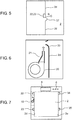
- projection unit 37 projecting inward from side wall surface 2d of heating chamber 2 may be provided as illustrated in FIG. 5 .
- FIG. 5 is a view illustrating a configuration example of projection unit 37 serving as the blocking unit in the exemplary embodiment of the present invention.
- the wall surface itself of heating chamber 2 is made of the material having low reflectivity (such as porcelain enamel steel sheet) with respect to the light from illumination lamps 22, 23, but the present invention is not limited to this case.
- the wall surface itself of heating chamber 2 may be made of any material (such as steel sheet plated with zinc or aluminum, or stainless steel sheet) different from the material having low reflectivity, and the wall surface may be covered (coated) with material having low reflectivity (such as fluorine resin).
- the effect of preventing the light from illumination lamps 22, 23 from being reflected can be provided.
- the material having low reflectivity when used, the material may be used for only side wall surface 2e facing side wall surface 2d having illumination lamps 22, 23, instead of being used for all the wall surfaces of heating chamber 2. In this case, even when the material having low reflectivity is not used for all the wall surfaces, the effect of preventing the light from illumination lamps 22, 23 from being reflected can be efficiently provided.
- camera 19 includes lens 24 and the imaging sensor as one example of the imager, but the present invention is not limited to this configuration.
- a camera not having a lens may be used, as long as an image can be captured.
- extension unit 31 rises perpendicularly from side wall surface 2d.
- extension unit 33 is curved.
- FIG. 6 is a view illustrating the extension unit 33 according to the present invention.
- extension unit 33 rises outward in a curved manner from a boundary with the wall surface of heating chamber 2.
- extension unit 33 has this shape, compared with the case where extension unit 33 rises perpendicularly from side wall surface 2d of heating chamber 2, a turbulent flow can be prevented from being generated and an air flow can be smoothed in the region facing the wind from air fan 20.
- the wind (air curtain) formed by air fan 20 can be prevented from entering heating chamber 2.
- two illumination lamps 22, 23 are provided as the illumination lamp for illuminating the inside of heating chamber 2, but the number is not limited to two, and one or three or more illumination lamps may be provided.
- the illumination lamps 22, 23 are provided on the side of side wall surface 2d of heating chamber 2, but the present invention is not limited to this configuration.
- another illumination lamp may be provided on the side of the wall surface other than side wall surface 2d.
- second illumination lamps 34, 35 may be provided on side wall surface 2e facing first illumination lamps 22, 23 in heating chamber 2.
- FIG. 7 is a view illustrating one example of a configuration of second illumination lamps 34, 35 in the exemplary embodiment of the present invention.
- first illumination lamps 22, 23 having the front-lit relation are turned on, while second illumination lamps 34, 35 having the back-lit relation are turned off, for example.
- camera 19 and second illumination lamps 34, 35 may be controlled by controller 36 for controlling application of the lights from first illumination lamps 22, 23 and second illumination lamps 34, 35 so that the light from second illumination lamps 34, 35 is not applied when the image is captured by camera 19.
- the second illumination lamps disposed on the side opposite to the wall surface having camera 19 are turned off when the image is captured.
- the light from the illumination lamps can be prevented from providing the back-lit relation to camera 19, so that camera 19 can be further improved in visibility.
- through-hole 25 for camera 19 and steam supply hole 12 for steam supply unit 7 are only provided as through-holes in the wall surface of heating chamber 2, but the present invention is not limited to this case, and another through-hole may be provided.
- a discharge hole for the steam may be provided in the wall surface of heating chamber 2 so that the steam in heating chamber 2 can be discharged to the outside of heating chamber 2.
- the discharge hole in this case is preferably formed in an upper part higher than 1/2 of the wall surface of heating chamber 2 (higher than half of the wall surface) because the steam moves upward in general.
- the specific values regarding the wavelength and the angle of the light and the specific example of the material of the wall surface of heating chamber 2 are described, but they are only the example and the present invention is not limited to those examples.
- display 5 is composed of the liquid crystal screen, but the present invention is not limited to this case, and another component having a display function may be used.
- operation unit 6 is composed of the plurality of buttons, but the present invention is not limited to this case, and another component which is operable by the user may be used.
- the heating cooker in the exemplary embodiment includes the heating chamber configured to house the food, the through-hole formed in the side wall surface of the heating chamber, the imager that captures the image in the heating chamber through the through-hole, the air blower that blows the air on the outside of the heating chamber, and the wind guide for guiding the wind from the air blower. Furthermore, the wind guide is disposed so that the wind from the air blower forms the air curtain passing through the space between the imager and the through-hole.
- the air curtain is formed between the imager and the through-hole, the air containing the hot air and the steam in the heating chamber can be prevented from reaching the camera through the through-hole.
- the air in the heating chamber can be prevented from reaching the imager, and the imager can be prevented from being harmfully affected, so that the imager can be improved in reliability and visibility.
- the heating cooker may further include the extension unit extending from the inner circumference of the through-hole toward the outside of the heating chamber.
- the wind from the air blower can be further prevented from entering the heating chamber.
- extension unit is curved outward at the boundary with the wall surface of the heating chamber.
- the air flow can be smoothed in the region facing the wind from the air blower.
- the wind from the air blower can be further prevented from entering the heating chamber.
- the air blower may be disposed below the imager, and the wind guide may be disposed to guide upward the wind from the air blower.
- the microwave supply unit configured to supply the microwave may be provided in the heating chamber.
- the steam supply unit configured to supply the steam may be provided in the heating chamber.
- the amount of steam is likely to increase in the heating chamber, but since the air curtain is formed, the steam can be prevented from reaching the imager through the through-hole.
- the imager can be improved in reliability and the imager can be improved in visibility.
- the discharge hole may be further provided in the wall surface of the heating chamber to discharge the steam in the heating chamber to the outside of the heating chamber.
- the steam supply unit since the steam can be discharged from the discharge hole, the amount of steam which could pass through the through-hole for the imager can be reduced. As a result, the imager can be improved in reliability.
- the effect of improving the reliability and visibility of the imager can be especially provided, so that the heating cooker is suitably used for the cooker for cooking the food by heat.
Description
- The present invention relates to a heating cooker for cooking a food by heat.
- A heating cooker has various components to check a state of a food in a heating chamber (refer to
Patent Literature 1, for example). A heating cooker disclosed inPatent Literature 1 includes an infrared ray sensor for detecting a temperature of a food. The food is cooked by heat while the infrared ray sensor receives an infrared ray from the food through an infrared ray through-hole to detect the temperature of the food. - In this configuration, the heating cooker in
Patent Literature 1 further includes a first air duct to send air into a heating chamber through the infrared ray through-hole formed in a wall surface of the heating chamber, and a second air duct diverging from the first air duct in a roughly perpendicular direction and provided between the infrared ray sensor and the infrared ray through-hole. Since the two air ducts are provided, scattered wastes of food in the heating chamber can be prevented from moving upward through an opening and staining the sensor. Furthermore, since not only the first air duct but also the second duct are provided to disperse the air ducts, a temperature in the heating chamber can be prevented from excessively dropping. -
JP 2003 056852 A -
JP H03 247920 A -
JP 2001 056124 A -
EP 2 444 732 A2 -
EP 1 741 986 A1 discloses a cooking apparatus for supplying steam to a heating chamber storing an object to be heated to thereby heat the object to be heated, which comprises steam supply means for supplying steam to the heating chamber, a fan for stirring up the steam supplied to the interior of the heating chamber, and temperature control means, by driving and rotating the fan, for controlling the atmospheric temperature of the interior of the heating chamber to be lower than the temperature of the steam supplied. - Here, the heating chamber for cooking the food experience a large change in circumstances including conditions such as temperature and moisture. As for a recent heating cooker, the circumstances in the heating chamber is likely to more largely change because more functions such as steam function have been added.
- Thus, as one of the additional functions of the heating cooker, a heating cooker including an imager to confirm a state of a food in the heating chamber has been developed. The heating cooker including the imager is to be devised to adapt to the change in circumstances in the heating chamber such as to be devised to improve reliability of the imager and to be devised to improve visibility of the imager.
- PTL 1: Unexamined Japanese Patent Publication No.
H03-247920 - The present invention was made in view of the above problems, and it is an object of the present invention to provide a heating cooker including an imager, in which the imager is improved in reliability and visibility.
- A heating cooker in the present invention includes a heating chamber configured to house a food, a through-hole formed in a wall surface of the heating chamber, an imager configured to capture an image in the heating chamber through the through-hole, an air blower configured to blow air on an outside of the heating chamber, and a wind guide configured to guide wind generated by the air blower. Thus, the wind guide is disposed so that the wind from the air blower forms an air curtain passing through a space between the imager and the through-hole.
- In the heating cooker having this configuration in the present invention, the imager can be improved in reliability and visibility.
-
-
FIG. 1 is a front view of a heating cooker in an exemplary embodiment of the present invention. -
FIG. 2 is a view illustrating a cross-sectional structure taken from a side of the heating cooker in the exemplary embodiment of the present invention. -
FIG. 3 is a view illustrating an internal configuration taken from a front of the heating cooker in the exemplary embodiment of the present invention. -
FIG. 4 is a view illustrating an enlarged cross-sectional configuration taken from the front of the heating cooker in the exemplary embodiment of the present invention. -
FIG. 5 is a view illustrating a configuration example of a projection unit serving as a blocking unit, in the exemplary embodiment of the present invention. -
FIG. 6 is a view illustrating an extension unit, according to the present invention. -
FIG. 7 is a view illustrating one example of a configuration of a second illumination lamp, in the exemplary embodiment of the present invention. - Hereinafter, an exemplary embodiment of a heating cooker in the present invention will be described with reference to the attached drawings. Furthermore, the heating cooker in the present invention is not limited to a heating cooker having a configuration described in the following exemplary embodiment.
-
FIG. 1 is a front view ofheating cooker 1 in the exemplary embodiment of the present invention.FIG. 2 is a view illustrating a cross-sectional structure ofheating cooker 1 in the exemplary embodiment of the present invention taken from a side. -
Heating cooker 1 is a device to cook a food (not illustrated) by heat inheating chamber 2. - As illustrated in
FIGS. 1 and 2 ,heating cooker 1 includesbody 3 incorporatingheating chamber 2, anddoor 4. -
Body 3 incorporatesheating chamber 2 and serves as an outer case ofheating cooker 1. As illustrated inFIG. 1 ,display 5 andoperation unit 6 are provided on an upper front surface ofbody 3. -
Display 5 displays an operating condition ofheating cooker 1.Display 5 in the exemplary embodiment is composed of a liquid crystal screen.Operation unit 6 is used when a user operatesheating cooker 1.Operation unit 6 in the exemplary embodiment is composed of a plurality of buttons to be pressed by the user. The user presses the button ofoperation unit 6 to control various operations ofheating cooker 1. The contents of the operation ofheating cooker 1 set inoperation unit 6 are displayed ondisplay 5. - In the exemplary embodiment, a wall surface of
heating chamber 2 inbody 3 is made of material selected from porcelain enamel steel sheet, stainless steel sheet, coated steel sheet, and the like. -
Door 4 is fixed tobody 3 openably.Door 4 in the exemplary embodiment is fixed to a lower front surface ofbody 3 so as to be rotatable in a front-back direction and has a handle (not illustrated) to be held by the user. The handle ofdoor 4 is used when the user opens or closesdoor 4.FIG. 1 illustrates a state in whichdoor 4 is closed (the user is not accessible to heating chamber 2), andFIG. 2 illustrates a state in whichdoor 4 is open (the user is accessible to heating chamber 2). - As illustrated in
FIG. 2 ,heating cooker 1 further includessteam supply unit 7,heater 8, andmicrowave supply unit 9 inbody 3. -
Steam supply unit 7 is a mechanism for supplying steam toheating chamber 2 to cook the food by heat.Steam supply unit 7 in the exemplary embodiment is disposed aboveupper wall surface 2a ofheating chamber 2 and includeswater tank 10 andsteam generating heater 11. -
Water tank 10 stores water to be used to generate steam.Steam generating heater 11 heats the water inwater tank 10. As illustrated inFIG. 2 ,steam generating heater 11 is provided adjacently towater tank 10. When the water inwater tank 10 is heated up to a predetermined temperature or higher bysteam generating heater 11, the water is evaporated and becomes steam. The steam is supplied toheating chamber 2 throughsteam supply hole 12 provided inupper wall surface 2a ofheating chamber 2 illustrated inFIG. 2 . In addition, water can be resupplied towater tank 10 by the user. -
Heater 8 is a mechanism for applying heat toheating chamber 2 by convection heat or radiation heat.Heater 8 in the exemplary embodiment is disposed behind (back side of)back wall surface 2b ofheating chamber 2 and includesconvection heater 13 such as a sheathed heater, andcentrifugal fan 14. Backwall surface 2b of theheating chamber 2 has a plurality of holes (not illustrated) so thatheating chamber 2 communicates with a space on the backside having heater 8. - In this configuration, air heated by
convection heater 13 is applied intoheating chamber 2 bycentrifugal fan 14, so thatheating chamber 2 and the food put inheating chamber 2 are heated by convection heat or radiation heat. -
Microwave supply unit 9 is a mechanism for supplying a microwave toheating chamber 2 to cook the food by heat inheating chamber 2.Microwave supply unit 9 in the exemplary embodiment is provided belowbottom wall surface 2c ofheating chamber 2 and includesmagnetron 15,waveguide 16a, andantenna 16b.Microwave supply unit 9 is covered withcover 2f made of material such as crystalized glass which transmits the microwave.Bottom wall surface 2c ofheating chamber 2 is composed of an upper surface ofcover 2f. -
Magnetron 15 is one example of a microwave generator for generating a microwave. The microwave generated frommagnetron 15 is applied towardantenna 16b.Antenna 16b diffuses the microwave frommagnetron 15 intoheating chamber 2. In this configuration, the microwave generated frommagnetron 15 is diffused byantenna 16b and supplied intoheating chamber 2 throughcover 2f. -
Heating cooker 1 in the exemplary embodiment further includesinverter 17.Inverter 17 is a circuit mechanism for drivingmagnetron 15. -
Heating cooker 1 in the exemplary embodiment further includes controller 36 (refer toFIG. 1 ).Controller 36 controls overall operations for driving the various components inheating cooker 1. For example,controller 36 executes a program previously stored in a memory, based on contents entered intooperation unit 6 so thatinverter 17 is driven to implement a predetermined cooking plan. - In the configuration described above,
heating cooker 1 in the exemplary embodiment can perform the steam heating bysteam supply unit 7, convection/radiation heating byheater 8, and microwave heating bymicrowave supply unit 9, for the food inheating chamber 2. These heating methods can be implemented individually or in combination. - Next, imaging
unit 18 provided inheating cooker 1 will be described with reference toFIGS. 3 and 4 . -
FIG. 3 is a view illustrating an internal configuration ofheating cooker 1 in the exemplary embodiment of the preset invention taken from a front surface, andFIG. 4 is an enlarged view illustrating a cross-sectional configuration ofheating cooker 1 taken from the front surface. -
Imaging unit 18 is a unit for taking a picture inheating chamber 2 to acquire an image inheating chamber 2. As illustrated inFIG. 3 ,imaging unit 18 in the exemplary embodiment is provided at a position adjacent to (on an outside of) oneside wall surface 2d (left side inFIG. 3 ) ofheating chamber 2. The image inheating chamber 2 captured by imagingunit 18 is displayed ondisplay 5 and can be confirmed by the user. -
FIG. 4 illustrates the enlarged view of a peripheral part ofimaging unit 18 nearside wall surface 2d ofheating cooker 1 illustrated inFIG. 3 . As illustrated inFIG. 4 ,imaging unit 18 in the exemplary embodiment includescamera 19,air fan 20,wind guide 21, andillumination lamps -
Camera 19 is one example of the imager configured to capture the image inheating chamber 2.Camera 19 in the exemplary embodiment includeslens 24 and an imaging sensor (not illustrated). The imaging sensor detects a light acquired throughlens 24 provided at a tip end ofcamera 19 to take the picture inheating chamber 2 and acquire the image inheating chamber 2. Through-hole 25 is formed inside wall surface 2d ofheating chamber 2 so that the image can be captured throughlens 24 ofcamera 19. - As illustrated in
FIG. 4 ,camera 19 is fixed tobody 3 on an outside ofside wall surface 2d ofheating chamber 2 to be away fromheating chamber 2.Lens 24 provided at the tip end ofcamera 19 is disposed to faceheating chamber 2 to fit the food inheating chamber 2 into a field of view through through-hole 25. In the example illustrated inFIG. 4 ,lens 24 is disposed so that an optical axis oflens 24 faces roughly a center ofheating chamber 2. InFIG. 4 , an imaging direction ofcamera 19 is represented by imaging direction A. - An angle formed by imaging direction A of
camera 19 towardheating chamber 2, with horizontally extendingbottom wall surface 2c (refer toFIG. 3 ) of heating chamber 2 (an angle formed with a horizontal direction) is referred to as an imaging angle ofcamera 19. Thus, according to the example illustrated inFIG. 4 , the imaging angle is set at 25° downward. In addition, this imaging angle may be 0° to 50° downward, depending on an angle of view ofcamera 19. -
Air fan 20 is fixed tobody 3 and disposed belowcamera 19 to blow air upward. -
Wind guide 21 is a member for guiding the wind fromair fan 20.Wind guide 21 in the exemplary embodiment is fixed to an upside ofair fan 20 and guides the wind fromair fan 20 upward so that the wind can pass throughspace 27 betweenlens 24 ofcamera 19 and through-hole 25. - Thus, the wind from
air fan 20 is guided bywind guide 21 and passes throughspace 27 betweenlens 24 ofcamera 19 and through-hole 25. Consequently, an air curtain is formed with respect tocamera 19. This air curtain will be described in detail below. -
Illumination lamps heating chamber 2 with light and illuminating the inside ofheating chamber 2. In the exemplary embodiment,illumination lamps camera 19, respectively.Illumination lamps - As illustrated in
FIG. 4 ,illumination lamps side wall surface 2d ofheating chamber 2. The light fromillumination lamps side wall surface 2e (refer toFIG. 3 ) provided opposite to sidewall surface 2d. The parallel light means a light moving in parallel, and the "roughly parallel light" in this specification means a light emitted from a point light source and converged by a lens like an LED having a lens. InFIG. 4 , a direction of the light fromillumination lamps illumination lamps - Here, when an angle formed by irradiation direction B of
illumination lamps bottom wall surface 2c (FIG. 3 ) of heating chamber 2 (that is, an angle formed with the horizontal direction) is referred to as an irradiation angle ofillumination lamps FIG. 4 . - Furthermore, imaging direction A of
camera 19 described above and irradiation direction B ofillumination lamps illumination lamps camera 19 are set to have a difference ranging from 0° to 25°. - Here, a wavelength of the light from
illumination lamps illumination lamps camera 19 ofheating cooker 1 and recognized by the user. - Furthermore, a wavelength showing maximum light emission intensity of the light from
illumination lamps illumination lamps illumination lamps heating chamber 2 bycamera 19 and the user. - Furthermore, in the exemplary embodiment, the material of the wall surface of
heating chamber 2 is the porcelain enamel steel sheet, for example. In this case, when the wavelength showing the maximum light emission intensity emitted fromillumination lamps heating chamber 2 with respect to the light wavelength emitted fromillumination lamps - As illustrated in
FIG. 4 ,first air duct 26, a second air duct (which will be described below), andthird air duct 28 are provided near the components ofimaging unit 18. -
First air duct 26 is provided to supply air from an outside ofheating chamber 1 toair fan 20.First air duct 26 extends fromair inlet 29 provided inoutside wall surface 32 ofbody 3, to an upstream opening end ofair fan 20. The air is made to pass throughfirst air duct 26 and then moved intoair fan 20.Air fan 20 generates wind from the air supplied fromfirst air duct 26, andwind guide 21 guides the wind. That is,wind guide 21 guides the wind towardspace 27 betweenlens 24 ofcamera 19 and through-hole 25. Thus, the second air duct is formed byair fan 20 andwind guide 21. -
Third air duct 28 is provided to exhaust the air which has passed throughspace 27 betweenlens 24 ofcamera 19 and through-hole 25, to the outside ofheating cooker 1.Third air duct 28 extends fromspace 27 betweenlens 24 ofcamera 19 and through-hole 25, toair outlet 30 provided inoutside wall surface 32 ofheating cooker 1. - In this configuration, after the air supplied from
air inlet 29 is blown byair fan 20, the wind is guided by wind guide 21 (and second air duct) to pass throughspace 27 betweenlens 24 ofcamera 19 and through-hole 25. Thus, the air curtain forcamera 19 is formed with respect to the space inheating chamber 2. After the wind has formed the air curtain, it is exhausted to the outside throughair outlet 30. -
Extension unit 31 is provided onside wall surface 2d ofheating chamber 2 having through-hole 25 as illustrated inFIG. 4 .Extension unit 31 extends from an inner circumference of through-hole 25 toward the outside (left direction on a sheet surface inFIG. 4 ) ofheating chamber 2. In an example not part of the present invention,extension unit 31 is formed to rise perpendicularly fromside wall surface 2d of heating chamber 2 (that is, extend in a horizontal direction). - Hereinafter, functions and effects of
imaging unit 18 and its peripheral components will be described. - In
heating chamber 2, the food and its ambient air are high in temperature especially during cooking by heat (such as 200°C). In addition to the fact that the temperature is high, the steam supplied fromsteam supply unit 7, and steam generated when the food is heated byheater 8 andmicrowave supply unit 9 are likely to be highly filled inheating chamber 2. Under this circumstances, sinceheating cooker 1 in the exemplary embodiment has the structure in which through-hole 25 forcamera 19 is provided inside wall surface 2d ofheating chamber 2, air containing the hot air and the steam inheating chamber 2 could escape to the outside ofheating chamber 2 through through-hole 25. When the air escapes to the outside ofheating chamber 2, it could reach camera 19 (especially lens 24) provided near through-hole 25. - In order to prevent this,
heating cooker 1 in the exemplary embodiment includesair fan 20 andwind guide 21 inimaging unit 18, andwind guide 21 is configured so that the wind from theair fan 20 forms the air curtain passing throughspace 27 betweencamera 19 and through-hole 25. Thus, the air inheating chamber 2 can be prevented from reaching camera 19 (lens 24 especially). That is,camera 19 can be prevented from being damaged (such as thermal damage tocamera 19 and loss of transparency of lens 24) due to the hot air and the steam, so thatcamera 19 can be improved in reliability. Furthermore, when the air curtain is formed, the wind guided bywind guide 21 can be prevented from being drawn intoheating chamber 2 through through-hole 25. - Furthermore, in a case where the imaging angle of
camera 19 is set upward, the wind of the air curtain hitting againstlens 24 ofcamera 19 is likely to escape tothird air duct 28, but in the exemplary embodiment, the imaging angle ofcamera 19 is set downward. In this case, the wind of the air curtain hitting againstlens 24 ofcamera 19 is likely to enterheating chamber 2 through through-hole 25 instead of escaping tothird air duct 28. Thus, since the imaging angle ofcamera 19 is set downward, the hot air and the steam can be prevented from being diffused from through-hole 25 towardimaging unit 18. - Still furthermore, in the exemplary embodiment, since
steam supply unit 7 is provided to supply the steam intoheating chamber 2,heating chamber 2 is likely to be filled with a large amount of steam, but when the air curtain is formed as described above, the steam can be prevented from reachingcamera 19 through through-hole 25. Thus,camera 19 can be improved in reliability and visibility. - Furthermore, in the exemplary embodiment,
wind guide 21 guides the wind along (toward) a surface oflens 24 and guides the wind only in a direction to form the air curtain (in an upper direction on the sheet surface inFIG. 4 ). In other words,wind guide 21 guides the wind to form a one-way air flow which passes through the space betweenlens 24 and through-hole 25. Thus, the air curtain can be more surely formed, and its blocking function with respect to the space inheating chamber 2 can be enhanced. - Furthermore, in the case where the air curtain is formed, it is preferable to more surely prevent the wind forming the air curtain from being drawn into
heating chamber 2 through through-hole 25. Thus, in the exemplary embodiment, as illustrated inFIG. 4 ,extension unit 31 extending outward from through-hole 25 is provided. Whenextension unit 31 is provided, the wind forming the air curtain can be further prevented from enteringheating chamber 2 through through-hole 25, compared with a case where only through-hole 25 is provided without providingextension unit 31. As a result, the air curtain can be more surely formed andcamera 19 can be improved in reliability. - Furthermore, in the exemplary embodiment, since
microwave supply unit 9 is provided to supply the microwave, the microwave inheating chamber 2 is preferably prevented from escaping to the outside through through-hole 25. Thus, sinceextension unit 31 is provided, the microwave inheating chamber 2 can be prevented from escaping to the outside through through-hole 25. As a result, the microwave is prevented from reachingcamera 19 which is likely to be affected by the microwave, so that a steady image can be obtained bycamera 19. - Furthermore, in the exemplary embodiment,
wind guide 21 is provided to guide the wind upward. As for commonly-usedheating cooker 1, an upper part ofheating chamber 2 inbody 3 tends to be higher in temperature than a lower part. Thus, in the exemplary embodiment, thewind guide 21 is disposed to guide the wind upward, so that the part which is relatively higher in temperature inbody 3 can be cooled down inheating cooker 1, compared with the case where the wind is guided downward. As a result,body 3 can be prevented from excessively increasing in temperature. - In addition to forming the air curtain as described above, in the exemplary embodiment,
heating chamber 2 is illuminated byillumination lamps camera 19 can be improved in visibility. - In the exemplary embodiment, especially,
illumination lamps camera 19 disposed onside wall surface 2d, that is, disposed onside wall surface 2d ofheating chamber 2 having through-hole 25. In this configuration,illumination lamps camera 19, so that a positional relation withcamera 19 is not a back-lit relation. Thus,camera 19 can be improved in visibility. Furthermore, to avoid the back-lit relation,illumination lamps upper wall surface 2a orbottom wall surface 2c other thanside wall surface 2d ofheating chamber 2. That is, whenillumination lamps side wall surface 2e) facing the wall surface (side wall surface 2d) havingcamera 19, the back-lit relation is not provided. - In addition, a front-lit relation is provided as the positional relation with
camera 19 whenillumination lamps camera 19 onsidewall surface 2d ofheating chamber 2, rather than just being disposed at the position not facingcamera 19. Mists formed when the steam inheating chamber 2 is condensed have a grain diameter of 1 µm to 100 µm, so that Mie scattering becomes geometric scattering, and forward scattering (scattering toward a travelling direction of light) largely occurs. Thus, since the front-lit relation is provided whenillumination lamps side wall surface 2d having camera 19, an effect of the forward scattering can be small. As a result,camera 19 can be further improved in visibility. - Furthermore, in the exemplary embodiment, as illustrated in
FIG. 4 , the difference between the illumination angle ofillumination lamps camera 19 is set within the predetermined range (such as the range of 0° to 25°), so that a high-precision front-lit relation can be provided. As a result,camera 19 can be further improved in visibility. - As for the light emitted from
illumination lamps heating chamber 2 can be clearly illuminated, andcamera 19 can be further improved in visibility. In addition, the range of 550 nm to 780 nm is also the range of the long wavelength light, so that the color of the light emitted fromillumination lamps heating chamber 2 can be clearly illuminated, so thatcamera 19 can be further improved in visibility. - Furthermore, in a case where the illumination lamp is a while LED provided by combining a plurality of emission spectra, the same effect can be provided when a spectrum having a maximum emission energy is set to range from 580 nm to 780 nm. In the exemplary embodiment,
illumination lamps camera 19 can be further improved in visibility. - The light emitted from
illumination lamps heating chamber 2. In the exemplary embodiment, the light emitted fromillumination lamps side wall surface 2e (refer toFIG. 3 ) facingside wall surface 2d. Here, in the exemplary embodiment, the wall surface inheating chamber 2 is made of the material of which the reflectivity with respect to the wavelength (such as 580 nm) of the light emitted fromillumination lamps illumination lamps side wall surface 2e facingside wall surface 2d) inheating chamber 2, so thatcamera 19 can be further improved in visibility. - In the configuration as described above,
steam supply hole 12 for supplying the steam is provided inupper wall surface 2a ofheating chamber 2. That is,steam supply hole 12 is disposed in the wall surface ofheating chamber 2 so as not to faceside wall surface 2d having camera 19 serving as the imager. Whensteam supply hole 12 is disposed in this way, the steam supplied fromsteam supply hole 12 is not likely to be directly applied tocamera 19, so that the visibility ofcamera 19 can be prevented from being harmfully affected by the steam. - As described above,
heating cooker 1 in the exemplary embodiment includesheating chamber 2 for housing the food, through-hole 25 formed inside wall surface 2d ofheating chamber 2, camera 19 (imager) for capturing the image inheating chamber 2 through through-hole 25, air fan 20 (air blower) for blowing the air on the outside ofheating chamber 2, andwind guide 21 for guiding the wind fromair fan 20. Furthermore,wind guide 21 is disposed so that the wind fromair fan 20 forms the air curtain passing throughspace 27 betweencamera 19 and through-hole 25. - In this configuration, the air curtain is formed between
camera 19 and through-hole 25, so that the air containing the hot air and the steam inheating chamber 2 can be prevented from reachingcamera 19 through through-hole 25. Thus, in the case wherecamera 19 is provided, the air inheating chamber 2 can be prevented from reachingcamera 19 and harmfully affectingcamera 19, so thatcamera 19 can be improved in reliability and visibility. - Furthermore,
heating cooker 1 in the exemplary embodiment includesheating chamber 2 for housing the food, through-hole 25 formed inside wall surface 2d ofheating chamber 2, camera 19 (imager) for capturing the image inheating chamber 2 through through-hole 25, andillumination lamps 22, 23 (first illumination lamp) provided onside wall surface 2d having through-hole 25 to irradiateheating chamber 2 with light. Thus,heating cooker 1 further includesillumination lamps heating chamber 2 in addition tocamera 19, so that even when transparency inheating chamber 2 is reduced due to the steam inheating chamber 2,camera 19 can be improved in visibility. In addition, sinceillumination lamps side wall surface 2d having through-hole 25, the back-lit relation is not provided betweencamera 19 and the first illumination lamp, so thatcamera 19 can be further improved in visibility. - The present invention has been described with reference to the exemplary embodiment described above, but the present invention is not limited to the exemplary embodiment described above. For example, in the exemplary embodiment,
steam supply unit 7 is provided, but the same effect can be provided in a cooking device in which steam is generated by a heater or a microwave heating, as a matter of course. - Furthermore, in the exemplary embodiment, the description has been given to
heating cooker 1 includingsteam supply unit 7,heater 8, andmicrowave supply unit 9, but the present invention is not limited to this configuration, and for example,heating cooker 1 may include at least one ofsteam supply unit 7,heater 8, andmicrowave supply unit 9. That is, as long asheating cooker 1 includes at least one of the steam heating function, heater heating function, and microwave heating function, the configuration of the exemplary embodiment may be applied and the same effect can be provided. - Furthermore, in the exemplary embodiment, as illustrated in
FIG. 4 ,illumination lamps side wall surface 2d, but the present invention is not limited to this case. For example, similar tocamera 19 illustrated inFIG. 4 ,illumination lamps side wall surface 2d. That is,illumination lamps side wall surface 2d ofheating chamber 2. Furthermore, as described above,illumination lamps upper wall surface 2a orbottom wall surface 2c which does not faceside wall surface 2d. - Furthermore, in the exemplary embodiment, through-
hole 25 forcamera 19 is only provided inside wall surface 2d, but the present invention is not limited to this case. For example, through-hole 25 may be provided not only inside wall surface 2d, but also partially inupper wall surface 2a (in a position ranging fromside wall surface 2d toupper wall surface 2a). That is, through-hole 25 is to be provided inside wall surface 2d "at least partially". - Furthermore, in the exemplary embodiment, the light emitted from
illumination lamps lens 24 ofcamera 19, but the present invention is not limited to this case. For example,illumination lamps lens 24 ofcamera 19. In this case, a blocking unit for blocking the light fromillumination lamps illumination lamps lens 24 ofcamera 19. Thus,camera 19 can be improved in visibility. For example, as the blocking unit,projection unit 37 projecting inward fromside wall surface 2d ofheating chamber 2 may be provided as illustrated inFIG. 5 . -
FIG. 5 is a view illustrating a configuration example ofprojection unit 37 serving as the blocking unit in the exemplary embodiment of the present invention. - Furthermore, in the exemplary embodiment, the wall surface itself of
heating chamber 2 is made of the material having low reflectivity (such as porcelain enamel steel sheet) with respect to the light fromillumination lamps heating chamber 2 may be made of any material (such as steel sheet plated with zinc or aluminum, or stainless steel sheet) different from the material having low reflectivity, and the wall surface may be covered (coated) with material having low reflectivity (such as fluorine resin). In this case also, the effect of preventing the light fromillumination lamps side wall surface 2e facingside wall surface 2d havingillumination lamps heating chamber 2. In this case, even when the material having low reflectivity is not used for all the wall surfaces, the effect of preventing the light fromillumination lamps - Furthermore, in the exemplary embodiment,
camera 19 includeslens 24 and the imaging sensor as one example of the imager, but the present invention is not limited to this configuration. For example, a camera not having a lens may be used, as long as an image can be captured. - Furthermore, in the example not part of the present invention,
extension unit 31 rises perpendicularly fromside wall surface 2d. According to the invention, as illustrated inFIG. 6 ,extension unit 33 is curved. -
FIG. 6 is a view illustrating theextension unit 33 according to the present invention. - More specifically, as illustrated in
FIG. 6 ,extension unit 33 rises outward in a curved manner from a boundary with the wall surface ofheating chamber 2. Whenextension unit 33 has this shape, compared with the case whereextension unit 33 rises perpendicularly fromside wall surface 2d ofheating chamber 2, a turbulent flow can be prevented from being generated and an air flow can be smoothed in the region facing the wind fromair fan 20. Thus, the wind (air curtain) formed byair fan 20 can be prevented from enteringheating chamber 2. - Furthermore, in the exemplary embodiment, two
illumination lamps heating chamber 2, but the number is not limited to two, and one or three or more illumination lamps may be provided. - Furthermore, in the exemplary embodiment, the
illumination lamps 22, 23 (first illumination lamp) are provided on the side ofside wall surface 2d ofheating chamber 2, but the present invention is not limited to this configuration. For example, another illumination lamp (second illumination lamp) may be provided on the side of the wall surface other thanside wall surface 2d. In this case, as illustrated inFIG. 7 ,second illumination lamps side wall surface 2e facingfirst illumination lamps heating chamber 2. -
FIG. 7 is a view illustrating one example of a configuration ofsecond illumination lamps - In this case, when
camera 19 takes an image,first illumination lamps second illumination lamps camera 19 andsecond illumination lamps controller 36 for controlling application of the lights fromfirst illumination lamps second illumination lamps second illumination lamps camera 19. With this control, the second illumination lamps disposed on the side opposite to the wallsurface having camera 19 are turned off when the image is captured. Thus, the light from the illumination lamps can be prevented from providing the back-lit relation tocamera 19, so thatcamera 19 can be further improved in visibility. - Furthermore, in the exemplary embodiment, through-
hole 25 forcamera 19 andsteam supply hole 12 forsteam supply unit 7 are only provided as through-holes in the wall surface ofheating chamber 2, but the present invention is not limited to this case, and another through-hole may be provided. For example, a discharge hole for the steam may be provided in the wall surface ofheating chamber 2 so that the steam inheating chamber 2 can be discharged to the outside ofheating chamber 2. Thus, in the case wheresteam supply unit 7 is provided especially, the steam can be discharged from the discharge hole, so that an amount of the steam which could be discharged from through-hole 25 forcamera 19 can be reduced. Thus,camera 19 can be improved in reliability. Furthermore, the discharge hole in this case is preferably formed in an upper part higher than 1/2 of the wall surface of heating chamber 2 (higher than half of the wall surface) because the steam moves upward in general. - In addition, in the exemplary embodiment, the specific values regarding the wavelength and the angle of the light and the specific example of the material of the wall surface of
heating chamber 2 are described, but they are only the example and the present invention is not limited to those examples. - Furthermore, in the exemplary embodiment,
display 5 is composed of the liquid crystal screen, but the present invention is not limited to this case, and another component having a display function may be used. In addition, in the exemplary embodiment,operation unit 6 is composed of the plurality of buttons, but the present invention is not limited to this case, and another component which is operable by the user may be used. - As described above, the heating cooker in the exemplary embodiment includes the heating chamber configured to house the food, the through-hole formed in the side wall surface of the heating chamber, the imager that captures the image in the heating chamber through the through-hole, the air blower that blows the air on the outside of the heating chamber, and the wind guide for guiding the wind from the air blower. Furthermore, the wind guide is disposed so that the wind from the air blower forms the air curtain passing through the space between the imager and the through-hole.
- In this configuration, since the air curtain is formed between the imager and the through-hole, the air containing the hot air and the steam in the heating chamber can be prevented from reaching the camera through the through-hole. Thus, in the case where the imager is provided, the air in the heating chamber can be prevented from reaching the imager, and the imager can be prevented from being harmfully affected, so that the imager can be improved in reliability and visibility.
- Furthermore, the heating cooker may further include the extension unit extending from the inner circumference of the through-hole toward the outside of the heating chamber.
- In this configuration, the wind from the air blower can be further prevented from entering the heating chamber.
- Furthermore, the extension unit is curved outward at the boundary with the wall surface of the heating chamber.
- In this configuration, compared with the case where the extension unit rises perpendicularly from the wall surface of the heating chamber, the air flow can be smoothed in the region facing the wind from the air blower. Thus, the wind from the air blower can be further prevented from entering the heating chamber.
- Furthermore, the air blower may be disposed below the imager, and the wind guide may be disposed to guide upward the wind from the air blower.
- In this configuration, the wind from the air blower is guided upward, so that the upper part of the heating cooker which is likely to increase in temperature can be efficiently cooled with the wind from the air blower.
- Furthermore, the microwave supply unit configured to supply the microwave may be provided in the heating chamber.
- Still furthermore, the steam supply unit configured to supply the steam may be provided in the heating chamber.
- In this configuration, the amount of steam is likely to increase in the heating chamber, but since the air curtain is formed, the steam can be prevented from reaching the imager through the through-hole. Thus, the imager can be improved in reliability and the imager can be improved in visibility.
- Furthermore, the discharge hole may be further provided in the wall surface of the heating chamber to discharge the steam in the heating chamber to the outside of the heating chamber.
- In this configuration, in the case where the steam supply unit is provided, since the steam can be discharged from the discharge hole, the amount of steam which could pass through the through-hole for the imager can be reduced. As a result, the imager can be improved in reliability.
- As described above, according to the present invention, the effect of improving the reliability and visibility of the imager can be especially provided, so that the heating cooker is suitably used for the cooker for cooking the food by heat.
-
- 1
- heating cooker
- 2
- heating chamber
- 2a
- upper wall surface
- 2b
- back wall surface
- 2c
- bottom wall surface
- 2d
- side wall surface
- 2e
- side wall surface
- 2f
- cover
- 3
- body
- 4
- door
- 5
- display
- 6
- operation unit
- 7
- steam supply unit
- 8
- heater
- 9
- microwave supply unit
- 10
- water tank
- 11
- steam generating heater
- 12
- steam supply hole
- 13
- convection heater
- 14
- centrifugal fan
- 15
- magnetron
- 16a
- waveguide
- 16b
- antenna
- 17
- inverter
- 18
- imaging unit
- 19
- camera (imager)
- 20
- air fan
- 21
- wind guide
- 22, 23
- illumination lamp (first illumination lamp)
- 24
- lens
- 25
- through-hole
- 26
- first air duct
- 27
- space
- 28
- third wind that
- 29
- air inlet
- 30
- air outlet
- 31
- extension unit
- 32
- outside wall surface
- 33
- extension unit
- 34, 35
- illumination lamp (second illumination lamp)
- 36
- controller
- 37
- projection unit (blocking unit)
Claims (5)
- A heating cooker (1) comprising:a heating chamber (2) configured to house a food;a through-hole (25) formed in a wall surface (2d) of the heating chamber;an imager (19) configured to capture an image in the heating chamber (2) through the through-hole;an air blower (20) configured to blow air on an outside of the heating chamber (2); anda wind guide (21) configured to guide wind generated by the air blower (20),
whereinthe wind guide (21) is disposed so that the wind from the air blower (20) forms an air curtain passing through a space between the imager (19) and the through-hole (25),characterized byan extension unit (33) configured to prevent the wind from being drawn into the heating chamber (2) through the through-hole (25) by extending from an inner circumference of the through-hole (25) toward the outside of the heating chamber (2), andwherein
a boundary between the extension unit (33) and the wall surface (2d) of the heating chamber (2) is curved outward. - The heating cooker (1) according to claim 1, wherein
the air blower (20) is disposed below the imager (19), and
the wind guide (21) is disposed to guide the wind from the air blower (20) upward. - The heating cooker (1) according to any one of claims 1 or 2, further comprising
a microwave supply unit (9) configured to supply a microwave, in the heating chamber (2). - The heating cooker (1) according to any one of claims 1 to 3, further comprising
a steam supply unit (7) configured to supply steam, in the heating chamber (2). - The heating cooker (1) according to claim 4, further comprising
a discharge hole formed in the wall surface of the heating chamber (2) to discharge the steam in the heating chamber (2) to the outside of the heating chamber (2).
Applications Claiming Priority (2)
| Application Number | Priority Date | Filing Date | Title |
|---|---|---|---|
| JP2014209417A JP6579301B2 (en) | 2014-10-10 | 2014-10-10 | Cooker |
| PCT/JP2015/005138 WO2016056246A1 (en) | 2014-10-10 | 2015-10-09 | Heating cooker |
Publications (3)
| Publication Number | Publication Date |
|---|---|
| EP3205941A1 EP3205941A1 (en) | 2017-08-16 |
| EP3205941A4 EP3205941A4 (en) | 2017-10-11 |
| EP3205941B1 true EP3205941B1 (en) | 2019-07-31 |
Family
ID=55652880
Family Applications (1)
| Application Number | Title | Priority Date | Filing Date |
|---|---|---|---|
| EP15848196.0A Active EP3205941B1 (en) | 2014-10-10 | 2015-10-09 | Heating cooker |
Country Status (5)
| Country | Link |
|---|---|
| US (1) | US10524317B2 (en) |
| EP (1) | EP3205941B1 (en) |
| JP (1) | JP6579301B2 (en) |
| CN (1) | CN106662332B (en) |
| WO (1) | WO2016056246A1 (en) |
Families Citing this family (25)
| Publication number | Priority date | Publication date | Assignee | Title |
|---|---|---|---|---|
| US9927129B2 (en) * | 2015-06-01 | 2018-03-27 | June Life, Inc. | Thermal management system and method for a connected oven |
| WO2017090244A1 (en) * | 2015-11-27 | 2017-06-01 | パナソニックIpマネジメント株式会社 | Heating cooker, method for controlling heating cooker, and heating cooking system |
| WO2018044067A1 (en) | 2016-09-01 | 2018-03-08 | Samsung Electronics Co., Ltd. | Oven |
| WO2018096885A1 (en) * | 2016-11-28 | 2018-05-31 | パナソニックIpマネジメント株式会社 | Heating cooker, method of controlling heating cooker, and heating cooking system |
| CN108571757B (en) | 2017-03-08 | 2021-06-08 | 博西华电器(江苏)有限公司 | Range hood's camera device and range hood |
| KR102366006B1 (en) | 2017-06-20 | 2022-02-23 | 삼성전자주식회사 | Oven |
| CN110250930A (en) | 2017-08-09 | 2019-09-20 | 沙克忍者运营有限责任公司 | Cooking system |
| DE102017220886A1 (en) | 2017-11-22 | 2019-05-23 | BSH Hausgeräte GmbH | Oven with sensor device and fan |
| KR102455063B1 (en) * | 2018-04-04 | 2022-10-14 | 엘지전자 주식회사 | Cooking appliance and method for controlling the same |
| JP7108820B2 (en) * | 2018-04-27 | 2022-07-29 | パナソニックIpマネジメント株式会社 | heating cooker |
| JP7108831B2 (en) * | 2018-04-27 | 2022-07-29 | パナソニックIpマネジメント株式会社 | heating cooker |
| JP7198972B2 (en) * | 2018-04-27 | 2023-01-05 | パナソニックIpマネジメント株式会社 | heating cooker |
| JP7253680B2 (en) * | 2018-05-18 | 2023-04-07 | パナソニックIpマネジメント株式会社 | heating cooker |
| US20200154943A1 (en) * | 2018-11-16 | 2020-05-21 | GMG Products LLC | Imaging system for cooking device |
| US20200260539A1 (en) * | 2019-02-12 | 2020-08-13 | Scp Science | System and method for microwave digestion of a sample |
| US20190254476A1 (en) | 2019-02-25 | 2019-08-22 | Sharkninja Operating Llc | Cooking device and components thereof |
| CN212788226U (en) | 2019-02-25 | 2021-03-26 | 沙克忍者运营有限责任公司 | Cooking system |
| DE102019206892A1 (en) * | 2019-05-13 | 2020-11-19 | BSH Hausgeräte GmbH | Cooking appliance with sensor units arranged outside the cooking space |
| US20200408416A1 (en) * | 2019-06-26 | 2020-12-31 | Bsh Home Appliances Corporation | Transparent oven bottom |
| JP7394589B2 (en) * | 2019-11-12 | 2023-12-08 | エスペック株式会社 | Environment shaping device and imaging device for environment shaping device |
| DE102020108572A1 (en) | 2020-03-27 | 2021-09-30 | Rational Aktiengesellschaft | Cooking device with optics |
| US11647861B2 (en) | 2020-03-30 | 2023-05-16 | Sharkninja Operating Llc | Cooking device and components thereof |
| TWI724879B (en) * | 2020-04-27 | 2021-04-11 | 志勇無限創意有限公司 | Image capturing module and food processing device comprising the same |
| US11940153B2 (en) | 2020-12-01 | 2024-03-26 | GMG Products, LLC | Fuel conditioner for grill |
| US11747024B2 (en) | 2020-12-30 | 2023-09-05 | B/E Aerospace, Inc. | Oven air curtain |
Family Cites Families (17)
| Publication number | Priority date | Publication date | Assignee | Title |
|---|---|---|---|---|
| JPH067012B2 (en) * | 1990-12-26 | 1994-01-26 | 三洋電機株式会社 | Cooking device |
| JPH06257756A (en) * | 1993-03-03 | 1994-09-16 | Toshiba Corp | Radar range |
| JPH06307645A (en) * | 1993-04-26 | 1994-11-01 | Toshiba Corp | Heating and cooling device |
| CN2162055Y (en) * | 1993-04-27 | 1994-04-13 | 天津开发区中导实业公司 | Furnace wall type industry camera protective sleeve |
| JPH06347173A (en) * | 1993-06-03 | 1994-12-20 | Nippon Cement Co Ltd | Burning zone monitoring method for kiln |
| JP2000104930A (en) * | 1998-09-28 | 2000-04-11 | Sanyo Electric Co Ltd | Heating/cooking apparatus |
| JP2001056123A (en) * | 1999-08-12 | 2001-02-27 | Toshiba Corp | Open range |
| JP3828319B2 (en) * | 1999-08-12 | 2006-10-04 | 株式会社東芝 | Microwave oven |
| JP2002243166A (en) * | 2001-02-20 | 2002-08-28 | Hitachi Hometec Ltd | Heat coking device |
| JP2003056852A (en) * | 2001-08-09 | 2003-02-26 | Hitachi Hometec Ltd | Cooking apparatus |
| JP2004263981A (en) * | 2003-03-04 | 2004-09-24 | Matsushita Electric Ind Co Ltd | High-frequency heating device |
| JP4472412B2 (en) * | 2004-04-22 | 2010-06-02 | パナソニック株式会社 | Cooker |
| JP2008292009A (en) * | 2007-05-22 | 2008-12-04 | Hoya Corp | Heating cooker |
| JP4825743B2 (en) * | 2007-06-27 | 2011-11-30 | 日立アプライアンス株式会社 | Cooker |
| JP4393541B2 (en) * | 2007-08-08 | 2010-01-06 | シャープ株式会社 | Packing, steam cooker, and method of manufacturing steam cooker |
| JP2010032149A (en) * | 2008-07-30 | 2010-02-12 | Panasonic Corp | Heating cooking device |
| KR101044147B1 (en) * | 2009-06-15 | 2011-06-24 | 엘지전자 주식회사 | Cooker and method for controlling the same |
-
2014
- 2014-10-10 JP JP2014209417A patent/JP6579301B2/en active Active
-
2015
- 2015-10-09 EP EP15848196.0A patent/EP3205941B1/en active Active
- 2015-10-09 CN CN201580044203.3A patent/CN106662332B/en active Active
- 2015-10-09 WO PCT/JP2015/005138 patent/WO2016056246A1/en active Application Filing
- 2015-10-09 US US15/510,544 patent/US10524317B2/en active Active
Non-Patent Citations (1)
| Title |
|---|
| None * |
Also Published As
| Publication number | Publication date |
|---|---|
| EP3205941A4 (en) | 2017-10-11 |
| CN106662332A (en) | 2017-05-10 |
| US20170303348A1 (en) | 2017-10-19 |
| JP2016080210A (en) | 2016-05-16 |
| US10524317B2 (en) | 2019-12-31 |
| CN106662332B (en) | 2019-09-17 |
| EP3205941A1 (en) | 2017-08-16 |
| JP6579301B2 (en) | 2019-09-25 |
| WO2016056246A1 (en) | 2016-04-14 |
Similar Documents
| Publication | Publication Date | Title |
|---|---|---|
| EP3205941B1 (en) | Heating cooker | |
| JP6508625B2 (en) | Cooker | |
| KR101388339B1 (en) | Electric oven | |
| JP4627745B2 (en) | Cooker | |
| US11585541B2 (en) | Heating cooking device | |
| JP6488177B2 (en) | Cooker | |
| CN109477641A (en) | Oven | |
| US20210003289A1 (en) | Heating cooker | |
| TWI607189B (en) | Heating conditioner | |
| JP7108820B2 (en) | heating cooker | |
| WO2019208526A1 (en) | Heating cooking device | |
| KR20210003664A (en) | Heating cooker | |
| JP2017003153A (en) | High-frequency heating cooker | |
| JP6749280B2 (en) | Cooker | |
| TWI686571B (en) | Heating conditioner | |
| JP5116863B2 (en) | Cooker | |
| JP6368652B2 (en) | Cooker | |
| JP6530973B2 (en) | High frequency heating cooker | |
| JP2023054377A (en) | Cooking device | |
| JP2014043973A (en) | Heating cooker |
Legal Events
| Date | Code | Title | Description |
|---|---|---|---|
| STAA | Information on the status of an ep patent application or granted ep patent |
Free format text: STATUS: THE INTERNATIONAL PUBLICATION HAS BEEN MADE |
|
| PUAI | Public reference made under article 153(3) epc to a published international application that has entered the european phase |
Free format text: ORIGINAL CODE: 0009012 |
|
| STAA | Information on the status of an ep patent application or granted ep patent |
Free format text: STATUS: REQUEST FOR EXAMINATION WAS MADE |
|
| 17P | Request for examination filed |
Effective date: 20170329 |
|
| AK | Designated contracting states |
Kind code of ref document: A1 Designated state(s): AL AT BE BG CH CY CZ DE DK EE ES FI FR GB GR HR HU IE IS IT LI LT LU LV MC MK MT NL NO PL PT RO RS SE SI SK SM TR |
|
| AX | Request for extension of the european patent |
Extension state: BA ME |
|
| RIC1 | Information provided on ipc code assigned before grant |
Ipc: F24C 15/00 20060101ALI20170831BHEP Ipc: F24C 7/08 20060101ALI20170831BHEP Ipc: F24C 7/02 20060101AFI20170831BHEP Ipc: F24C 15/32 20060101ALI20170831BHEP Ipc: H05B 6/64 20060101ALI20170831BHEP |
|
| A4 | Supplementary search report drawn up and despatched |
Effective date: 20170907 |
|
| DAV | Request for validation of the european patent (deleted) | ||
| DAX | Request for extension of the european patent (deleted) | ||
| REG | Reference to a national code |
Ref country code: DE Ref legal event code: R079 Ref document number: 602015034981 Country of ref document: DE Free format text: PREVIOUS MAIN CLASS: F24C0007020000 Ipc: F24C0015000000 |
|
| GRAP | Despatch of communication of intention to grant a patent |
Free format text: ORIGINAL CODE: EPIDOSNIGR1 |
|
| STAA | Information on the status of an ep patent application or granted ep patent |
Free format text: STATUS: GRANT OF PATENT IS INTENDED |
|
| RIC1 | Information provided on ipc code assigned before grant |
Ipc: H05B 6/64 20060101ALI20190221BHEP Ipc: F24C 15/00 20060101AFI20190221BHEP Ipc: F24C 15/32 20060101ALI20190221BHEP Ipc: F24C 7/08 20060101ALI20190221BHEP |
|
| INTG | Intention to grant announced |
Effective date: 20190318 |
|
| GRAS | Grant fee paid |
Free format text: ORIGINAL CODE: EPIDOSNIGR3 |
|
| GRAA | (expected) grant |
Free format text: ORIGINAL CODE: 0009210 |
|
| STAA | Information on the status of an ep patent application or granted ep patent |
Free format text: STATUS: THE PATENT HAS BEEN GRANTED |
|
| AK | Designated contracting states |
Kind code of ref document: B1 Designated state(s): AL AT BE BG CH CY CZ DE DK EE ES FI FR GB GR HR HU IE IS IT LI LT LU LV MC MK MT NL NO PL PT RO RS SE SI SK SM TR |
|
| REG | Reference to a national code |
Ref country code: CH Ref legal event code: EP Ref country code: GB Ref legal event code: FG4D |
|
| REG | Reference to a national code |
Ref country code: AT Ref legal event code: REF Ref document number: 1161291 Country of ref document: AT Kind code of ref document: T Effective date: 20190815 |
|
| REG | Reference to a national code |
Ref country code: IE Ref legal event code: FG4D |
|
| REG | Reference to a national code |
Ref country code: DE Ref legal event code: R096 Ref document number: 602015034981 Country of ref document: DE |
|
| REG | Reference to a national code |
Ref country code: NL Ref legal event code: MP Effective date: 20190731 |
|
| REG | Reference to a national code |
Ref country code: LT Ref legal event code: MG4D |
|
| REG | Reference to a national code |
Ref country code: AT Ref legal event code: MK05 Ref document number: 1161291 Country of ref document: AT Kind code of ref document: T Effective date: 20190731 |
|
| PG25 | Lapsed in a contracting state [announced via postgrant information from national office to epo] |
Ref country code: FI Free format text: LAPSE BECAUSE OF FAILURE TO SUBMIT A TRANSLATION OF THE DESCRIPTION OR TO PAY THE FEE WITHIN THE PRESCRIBED TIME-LIMIT Effective date: 20190731 Ref country code: LT Free format text: LAPSE BECAUSE OF FAILURE TO SUBMIT A TRANSLATION OF THE DESCRIPTION OR TO PAY THE FEE WITHIN THE PRESCRIBED TIME-LIMIT Effective date: 20190731 Ref country code: NL Free format text: LAPSE BECAUSE OF FAILURE TO SUBMIT A TRANSLATION OF THE DESCRIPTION OR TO PAY THE FEE WITHIN THE PRESCRIBED TIME-LIMIT Effective date: 20190731 Ref country code: PT Free format text: LAPSE BECAUSE OF FAILURE TO SUBMIT A TRANSLATION OF THE DESCRIPTION OR TO PAY THE FEE WITHIN THE PRESCRIBED TIME-LIMIT Effective date: 20191202 Ref country code: BG Free format text: LAPSE BECAUSE OF FAILURE TO SUBMIT A TRANSLATION OF THE DESCRIPTION OR TO PAY THE FEE WITHIN THE PRESCRIBED TIME-LIMIT Effective date: 20191031 Ref country code: NO Free format text: LAPSE BECAUSE OF FAILURE TO SUBMIT A TRANSLATION OF THE DESCRIPTION OR TO PAY THE FEE WITHIN THE PRESCRIBED TIME-LIMIT Effective date: 20191031 Ref country code: AT Free format text: LAPSE BECAUSE OF FAILURE TO SUBMIT A TRANSLATION OF THE DESCRIPTION OR TO PAY THE FEE WITHIN THE PRESCRIBED TIME-LIMIT Effective date: 20190731 Ref country code: HR Free format text: LAPSE BECAUSE OF FAILURE TO SUBMIT A TRANSLATION OF THE DESCRIPTION OR TO PAY THE FEE WITHIN THE PRESCRIBED TIME-LIMIT Effective date: 20190731 Ref country code: SE Free format text: LAPSE BECAUSE OF FAILURE TO SUBMIT A TRANSLATION OF THE DESCRIPTION OR TO PAY THE FEE WITHIN THE PRESCRIBED TIME-LIMIT Effective date: 20190731 |
|
| PG25 | Lapsed in a contracting state [announced via postgrant information from national office to epo] |
Ref country code: RS Free format text: LAPSE BECAUSE OF FAILURE TO SUBMIT A TRANSLATION OF THE DESCRIPTION OR TO PAY THE FEE WITHIN THE PRESCRIBED TIME-LIMIT Effective date: 20190731 Ref country code: LV Free format text: LAPSE BECAUSE OF FAILURE TO SUBMIT A TRANSLATION OF THE DESCRIPTION OR TO PAY THE FEE WITHIN THE PRESCRIBED TIME-LIMIT Effective date: 20190731 Ref country code: ES Free format text: LAPSE BECAUSE OF FAILURE TO SUBMIT A TRANSLATION OF THE DESCRIPTION OR TO PAY THE FEE WITHIN THE PRESCRIBED TIME-LIMIT Effective date: 20190731 Ref country code: AL Free format text: LAPSE BECAUSE OF FAILURE TO SUBMIT A TRANSLATION OF THE DESCRIPTION OR TO PAY THE FEE WITHIN THE PRESCRIBED TIME-LIMIT Effective date: 20190731 Ref country code: GR Free format text: LAPSE BECAUSE OF FAILURE TO SUBMIT A TRANSLATION OF THE DESCRIPTION OR TO PAY THE FEE WITHIN THE PRESCRIBED TIME-LIMIT Effective date: 20191101 |
|
| PG25 | Lapsed in a contracting state [announced via postgrant information from national office to epo] |
Ref country code: TR Free format text: LAPSE BECAUSE OF FAILURE TO SUBMIT A TRANSLATION OF THE DESCRIPTION OR TO PAY THE FEE WITHIN THE PRESCRIBED TIME-LIMIT Effective date: 20190731 |
|
| PG25 | Lapsed in a contracting state [announced via postgrant information from national office to epo] |
Ref country code: EE Free format text: LAPSE BECAUSE OF FAILURE TO SUBMIT A TRANSLATION OF THE DESCRIPTION OR TO PAY THE FEE WITHIN THE PRESCRIBED TIME-LIMIT Effective date: 20190731 Ref country code: DK Free format text: LAPSE BECAUSE OF FAILURE TO SUBMIT A TRANSLATION OF THE DESCRIPTION OR TO PAY THE FEE WITHIN THE PRESCRIBED TIME-LIMIT Effective date: 20190731 Ref country code: IT Free format text: LAPSE BECAUSE OF FAILURE TO SUBMIT A TRANSLATION OF THE DESCRIPTION OR TO PAY THE FEE WITHIN THE PRESCRIBED TIME-LIMIT Effective date: 20190731 Ref country code: RO Free format text: LAPSE BECAUSE OF FAILURE TO SUBMIT A TRANSLATION OF THE DESCRIPTION OR TO PAY THE FEE WITHIN THE PRESCRIBED TIME-LIMIT Effective date: 20190731 Ref country code: PL Free format text: LAPSE BECAUSE OF FAILURE TO SUBMIT A TRANSLATION OF THE DESCRIPTION OR TO PAY THE FEE WITHIN THE PRESCRIBED TIME-LIMIT Effective date: 20190731 |
|
| PG25 | Lapsed in a contracting state [announced via postgrant information from national office to epo] |
Ref country code: SK Free format text: LAPSE BECAUSE OF FAILURE TO SUBMIT A TRANSLATION OF THE DESCRIPTION OR TO PAY THE FEE WITHIN THE PRESCRIBED TIME-LIMIT Effective date: 20190731 Ref country code: CZ Free format text: LAPSE BECAUSE OF FAILURE TO SUBMIT A TRANSLATION OF THE DESCRIPTION OR TO PAY THE FEE WITHIN THE PRESCRIBED TIME-LIMIT Effective date: 20190731 Ref country code: IS Free format text: LAPSE BECAUSE OF FAILURE TO SUBMIT A TRANSLATION OF THE DESCRIPTION OR TO PAY THE FEE WITHIN THE PRESCRIBED TIME-LIMIT Effective date: 20200224 Ref country code: MC Free format text: LAPSE BECAUSE OF FAILURE TO SUBMIT A TRANSLATION OF THE DESCRIPTION OR TO PAY THE FEE WITHIN THE PRESCRIBED TIME-LIMIT Effective date: 20190731 Ref country code: SM Free format text: LAPSE BECAUSE OF FAILURE TO SUBMIT A TRANSLATION OF THE DESCRIPTION OR TO PAY THE FEE WITHIN THE PRESCRIBED TIME-LIMIT Effective date: 20190731 |
|
| REG | Reference to a national code |
Ref country code: CH Ref legal event code: PL |
|
| REG | Reference to a national code |
Ref country code: DE Ref legal event code: R097 Ref document number: 602015034981 Country of ref document: DE |
|
| PLBE | No opposition filed within time limit |
Free format text: ORIGINAL CODE: 0009261 |
|
| STAA | Information on the status of an ep patent application or granted ep patent |
Free format text: STATUS: NO OPPOSITION FILED WITHIN TIME LIMIT |
|
| PG2D | Information on lapse in contracting state deleted |
Ref country code: IS |
|
| PG25 | Lapsed in a contracting state [announced via postgrant information from national office to epo] |
Ref country code: CH Free format text: LAPSE BECAUSE OF NON-PAYMENT OF DUE FEES Effective date: 20191031 Ref country code: LU Free format text: LAPSE BECAUSE OF NON-PAYMENT OF DUE FEES Effective date: 20191009 Ref country code: LI Free format text: LAPSE BECAUSE OF NON-PAYMENT OF DUE FEES Effective date: 20191031 Ref country code: IS Free format text: LAPSE BECAUSE OF FAILURE TO SUBMIT A TRANSLATION OF THE DESCRIPTION OR TO PAY THE FEE WITHIN THE PRESCRIBED TIME-LIMIT Effective date: 20191030 |
|
| 26N | No opposition filed |
Effective date: 20200603 |
|
| REG | Reference to a national code |
Ref country code: BE Ref legal event code: MM Effective date: 20191031 |
|
| PG25 | Lapsed in a contracting state [announced via postgrant information from national office to epo] |
Ref country code: SI Free format text: LAPSE BECAUSE OF FAILURE TO SUBMIT A TRANSLATION OF THE DESCRIPTION OR TO PAY THE FEE WITHIN THE PRESCRIBED TIME-LIMIT Effective date: 20190731 Ref country code: BE Free format text: LAPSE BECAUSE OF NON-PAYMENT OF DUE FEES Effective date: 20191031 |
|
| GBPC | Gb: european patent ceased through non-payment of renewal fee |
Effective date: 20191031 |
|
| PG25 | Lapsed in a contracting state [announced via postgrant information from national office to epo] |
Ref country code: GB Free format text: LAPSE BECAUSE OF NON-PAYMENT OF DUE FEES Effective date: 20191031 Ref country code: IE Free format text: LAPSE BECAUSE OF NON-PAYMENT OF DUE FEES Effective date: 20191009 Ref country code: FR Free format text: LAPSE BECAUSE OF NON-PAYMENT OF DUE FEES Effective date: 20191031 |
|
| PG25 | Lapsed in a contracting state [announced via postgrant information from national office to epo] |
Ref country code: CY Free format text: LAPSE BECAUSE OF FAILURE TO SUBMIT A TRANSLATION OF THE DESCRIPTION OR TO PAY THE FEE WITHIN THE PRESCRIBED TIME-LIMIT Effective date: 20190731 |
|
| PG25 | Lapsed in a contracting state [announced via postgrant information from national office to epo] |
Ref country code: MT Free format text: LAPSE BECAUSE OF FAILURE TO SUBMIT A TRANSLATION OF THE DESCRIPTION OR TO PAY THE FEE WITHIN THE PRESCRIBED TIME-LIMIT Effective date: 20190731 Ref country code: HU Free format text: LAPSE BECAUSE OF FAILURE TO SUBMIT A TRANSLATION OF THE DESCRIPTION OR TO PAY THE FEE WITHIN THE PRESCRIBED TIME-LIMIT; INVALID AB INITIO Effective date: 20151009 |
|
| PG25 | Lapsed in a contracting state [announced via postgrant information from national office to epo] |
Ref country code: MK Free format text: LAPSE BECAUSE OF FAILURE TO SUBMIT A TRANSLATION OF THE DESCRIPTION OR TO PAY THE FEE WITHIN THE PRESCRIBED TIME-LIMIT Effective date: 20190731 |
|
| PGFP | Annual fee paid to national office [announced via postgrant information from national office to epo] |
Ref country code: DE Payment date: 20231020 Year of fee payment: 9 |