EP3205901B1 - Vibration damper - Google Patents
Vibration damper Download PDFInfo
- Publication number
- EP3205901B1 EP3205901B1 EP17154693.0A EP17154693A EP3205901B1 EP 3205901 B1 EP3205901 B1 EP 3205901B1 EP 17154693 A EP17154693 A EP 17154693A EP 3205901 B1 EP3205901 B1 EP 3205901B1
- Authority
- EP
- European Patent Office
- Prior art keywords
- cam surface
- curved profile
- came
- cam follower
- rotation
- Prior art date
- Legal status (The legal status is an assumption and is not a legal conclusion. Google has not performed a legal analysis and makes no representation as to the accuracy of the status listed.)
- Active
Links
Images

Classifications
-
- F—MECHANICAL ENGINEERING; LIGHTING; HEATING; WEAPONS; BLASTING
- F16—ENGINEERING ELEMENTS AND UNITS; GENERAL MEASURES FOR PRODUCING AND MAINTAINING EFFECTIVE FUNCTIONING OF MACHINES OR INSTALLATIONS; THERMAL INSULATION IN GENERAL
- F16F—SPRINGS; SHOCK-ABSORBERS; MEANS FOR DAMPING VIBRATION
- F16F15/00—Suppression of vibrations in systems; Means or arrangements for avoiding or reducing out-of-balance forces, e.g. due to motion
- F16F15/10—Suppression of vibrations in rotating systems by making use of members moving with the system
- F16F15/12—Suppression of vibrations in rotating systems by making use of members moving with the system using elastic members or friction-damping members, e.g. between a rotating shaft and a gyratory mass mounted thereon
- F16F15/131—Suppression of vibrations in rotating systems by making use of members moving with the system using elastic members or friction-damping members, e.g. between a rotating shaft and a gyratory mass mounted thereon the rotating system comprising two or more gyratory masses
- F16F15/133—Suppression of vibrations in rotating systems by making use of members moving with the system using elastic members or friction-damping members, e.g. between a rotating shaft and a gyratory mass mounted thereon the rotating system comprising two or more gyratory masses using springs as elastic members, e.g. metallic springs
- F16F15/1336—Leaf springs, e.g. radially extending
-
- F—MECHANICAL ENGINEERING; LIGHTING; HEATING; WEAPONS; BLASTING
- F16—ENGINEERING ELEMENTS AND UNITS; GENERAL MEASURES FOR PRODUCING AND MAINTAINING EFFECTIVE FUNCTIONING OF MACHINES OR INSTALLATIONS; THERMAL INSULATION IN GENERAL
- F16F—SPRINGS; SHOCK-ABSORBERS; MEANS FOR DAMPING VIBRATION
- F16F15/00—Suppression of vibrations in systems; Means or arrangements for avoiding or reducing out-of-balance forces, e.g. due to motion
- F16F15/10—Suppression of vibrations in rotating systems by making use of members moving with the system
- F16F15/12—Suppression of vibrations in rotating systems by making use of members moving with the system using elastic members or friction-damping members, e.g. between a rotating shaft and a gyratory mass mounted thereon
- F16F15/121—Suppression of vibrations in rotating systems by making use of members moving with the system using elastic members or friction-damping members, e.g. between a rotating shaft and a gyratory mass mounted thereon using springs as elastic members, e.g. metallic springs
- F16F15/1213—Spiral springs, e.g. lying in one plane, around axis of rotation
-
- F—MECHANICAL ENGINEERING; LIGHTING; HEATING; WEAPONS; BLASTING
- F16—ENGINEERING ELEMENTS AND UNITS; GENERAL MEASURES FOR PRODUCING AND MAINTAINING EFFECTIVE FUNCTIONING OF MACHINES OR INSTALLATIONS; THERMAL INSULATION IN GENERAL
- F16F—SPRINGS; SHOCK-ABSORBERS; MEANS FOR DAMPING VIBRATION
- F16F15/00—Suppression of vibrations in systems; Means or arrangements for avoiding or reducing out-of-balance forces, e.g. due to motion
- F16F15/10—Suppression of vibrations in rotating systems by making use of members moving with the system
- F16F15/12—Suppression of vibrations in rotating systems by making use of members moving with the system using elastic members or friction-damping members, e.g. between a rotating shaft and a gyratory mass mounted thereon
- F16F15/131—Suppression of vibrations in rotating systems by making use of members moving with the system using elastic members or friction-damping members, e.g. between a rotating shaft and a gyratory mass mounted thereon the rotating system comprising two or more gyratory masses
- F16F15/133—Suppression of vibrations in rotating systems by making use of members moving with the system using elastic members or friction-damping members, e.g. between a rotating shaft and a gyratory mass mounted thereon the rotating system comprising two or more gyratory masses using springs as elastic members, e.g. metallic springs
- F16F15/1333—Spiral springs, e.g. lying in one plane, around axis of rotation
-
- F—MECHANICAL ENGINEERING; LIGHTING; HEATING; WEAPONS; BLASTING
- F16—ENGINEERING ELEMENTS AND UNITS; GENERAL MEASURES FOR PRODUCING AND MAINTAINING EFFECTIVE FUNCTIONING OF MACHINES OR INSTALLATIONS; THERMAL INSULATION IN GENERAL
- F16F—SPRINGS; SHOCK-ABSORBERS; MEANS FOR DAMPING VIBRATION
- F16F2230/00—Purpose; Design features
- F16F2230/0052—Physically guiding or influencing
- F16F2230/0064—Physically guiding or influencing using a cam
Definitions
- the invention relates to a torsion damper for equipping a torque transmission device.
- the invention relates more particularly to the field of transmissions for a motor vehicle, the invention being intended to transmit the engine torque between the engine and the wheels of the vehicle.
- This damper can be applied to a transmission device for a manual gearbox automobile, such as a damped friction disc or a double damping flywheel, as well as to a transmission device for an automobile with an automatic gearbox, such as a gearbox. torque converter or lock-up.
- Torsional dampers are known whose input and output elements are coupled in rotation by damping means for transmitting a torque and damping rotation acyclisms.
- the damping means are generally helical, bent, circumferentially disposed springs in an annular, sealed chamber which is formed between the input and output members.
- damping proposed by these dampers is not entirely satisfactory, in particular because of the high friction, and it has also been proposed to produce torsion dampers with a blade, as described in the document FR3000155 which illustrates a torsion damper comprising elastic damping means formed by an elastic blade provided with a cam, and cooperating with a cam follower.
- the invention improves the prior art solutions and provides an optimized elastic blade torsion damper, and whose blade and cam follower resistance is improved.
- the Hertz stresses generated by the rolling of the cam follower on the cam surface can be mastered. It is possible to avoid excessive accumulation of stresses, especially on sensitive areas of the blade and the cam follower, especially in the case of relative tilting between the blade and the cam follower, that is to say when tilting of the cam follower and the blade is changing. The blade and the cam follower become more resistant. Also, the curved profile is arranged to move the stress concentrations away from the corners of the blade. Corner means the junction areas between the cam surface and the flanks of the blade.
- the damper is a double damping flywheel in which the first element is formed by one of the primary and secondary flywheels and the second element is formed by the other primary and secondary flywheels.
- the invention also relates to a blade as described above, for a torsion damper, for a torque transmission device, in particular for an automobile, in particular for a clutch device.
- the terms "external” and “internal” as well as the “axial” and “radial” orientations will be used to designate, according to the definitions given in the description, elements of the torsion damper.
- the "radial” orientation is directed orthogonally to the axis (X) of rotation of the elements of the torsion damper determining the "axial” orientation and, from the inside towards the outside while moving away of said axis, the "circumferential” orientation is directed orthogonally to the axis of rotation of the torsion damper and orthogonal to the radial direction.
- an element described as circumferentially developing is an element whose component develops in a circumferential direction.
- the indication of an angle is interpreted as delimited by two lines of a plane perpendicular to the axis of rotation X and secant at said axis of rotation X.
- the terms “external” and “internal” are used to define the relative position of one element relative to another, with reference to the axis of rotation of the torsion damper, an element close to the axis is thus described as internal as opposed to an external element located radially at the periphery.
- the thickness of the blade extends parallel to the X axis.
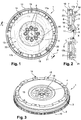
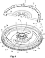
- FIGS 1 to 4 illustrate the general operation of a torsion damper with elastically deformable blades fitted to a double damping flywheel 1.
- the first and second elements are formed here respectively by the flywheels of secondary and primary inertia.
- the double damping flywheel 1 comprises a primary flywheel 2, intended to be fixed at the end of a crankshaft of an internal combustion engine, not shown, and a secondary flywheel 3 which is centered and guided on the primary flywheel 2 by means of a rolling ball bearing 4.
- the secondary flywheel 3 is intended to form the reaction plate of a clutch, not shown, connected to the input shaft of a gearbox.
- the primary flywheels 2 and secondary 3 are intended to be mounted movable about an axis of rotation X and are, moreover, rotatable relative to each other about said axis X.
- the primary flywheel 2 comprises a radially inner hub 5 supporting the rolling bearing 4, an annular portion 6 extending radially from the hub 5 and a cylindrical portion 7 extending axially on the side opposite the motor, from the outer periphery of the the annular portion 6.
- the annular portion 6 is provided, on the one hand, with fastening screw holes 8 for attaching the primary flywheel 2 to the crankshaft of the engine and, on the other hand, to orifices for passage of rivets 9 for fixing a transmission member on the primary flywheel 2.
- the primary flywheel 2 carries, on its outer periphery, a ring gear 10 for driving in rotation the primary flywheel 2, to the using a starter.
- the hub 5 of the primary flywheel has a shoulder 11 serving to support an inner ring of the rolling bearing 4 and which retains said inner ring towards the engine.
- the secondary flywheel 3 has on its inner periphery a shoulder 12 serving to support an outer ring of the rolling bearing 4 and retaining said outer ring in the opposite direction to the motor.
- the secondary flywheel 3 comprises a flat annular surface 13, turned on the opposite side to the primary flywheel 2, forming a bearing surface for a friction lining of a clutch disc, not shown.
- the secondary flywheel 3 has, close to its outer edge, pads 14 and orifices 15 for mounting a clutch cover.
- the secondary flywheel 3 further comprises orifices 16, arranged vis-à-vis the orifices formed in the primary flywheel 2, and for the passage of the screws 8, when mounting the double damping flywheel 1 on the crankshaft.
- the primary flywheels 2 and secondary 3 are coupled in rotation by a transmission member 30.
- this damping means comprises two resilient blades 17, 17b mounted integral in rotation with the primary flywheel 2.
- the elastic blades 17, 17b are carried by an annular body 18 provided with orifices allowing the rivets 9 to pass through. attachment to the primary flywheel 2.
- the annular body 18 further includes orifices 19 for the passage of the screws 8 for fixing the double damping flywheel 1 to the nose of the crankshaft.
- the two resilient blades 17, 17b are symmetrical with respect to the axis of rotation X of the clutch disc.
- the resilient blades 17, 17b have a cam surface 20 which extends circumferentially about the axis of rotation X.
- the secondary flywheel 3 comprises two cam followers 24 arranged to each cooperate with a cam surface 20.
- the elastic blades 17, 17b comprise a flexible portion extending substantially circumferentially.
- Each elastic blade 17, 17b may, as desired, be made in one piece or be composed of a plurality of lamellae arranged axially against each other.
- the cam followers 24 comprise rollers 21 carried by cylindrical rods 22 fixed on the one hand to the secondary flywheel 3 and on the other hand to a web 23.
- the rollers 21 are rotatably mounted on the cylindrical rods 22 around an axis of rotation parallel to the axis of rotation X.
- the rollers 21 are held in abutment against their cam surface 20 and are arranged to roll against said cam surface 20 during a relative movement between the primary flywheels 2 and secondary 3.
- the rollers 21 are radially disposed outside their respective cam surface 20 so as to radially maintain the resilient blades 17, 17b when subjected to centrifugal force.
- the rollers 21 are advantageously mounted in rotation on the cylindrical rods by means of a rolling bearing.
- the rolling bearing may be a ball bearing or roller.
- the rollers 21 have an anti-friction coating.
- the primary and secondary flywheels 2 and 3 occupy a relative angular position of rest in the absence of torque transmission.
- the cam surface 20 has a neutral position occupied by the cam follower 24 when no torque is transmitted by the damper.
- the cam follower is in the neutral position of the cam surface 20.
- Each cam surface 20 is arranged such that, for an angular displacement between the primary flywheel 2 and the secondary flywheel 3, relative to a relative angular position of rest, each roller 21 moves on the cam surface 20 which is clean and, in doing so, exerts a bending force on the elastic blade 17, 17b.
- the elastic blade 17, 17b exerts on the roller 21 a return force which tends to bring the primary flywheels 2 and secondary 3 to their relative angular position of rest.
- This reaction force is an elastic restoring force exerted by the flexible blade on the roller 21 in response to the elastic flexion of the blade 17a, 17b.
- the reaction force is an elastic restoring force exerted solely by the flexible blade 17a, 17b on the roller 21 in response to the elastic deformation of the blade.
- the bending movement of the blade is accompanied by a relative rotation between the primary and secondary flywheels to dampen rotational acyclisms between the primary and secondary flywheels.
- the cam followers 24 move on the cam surfaces 20 during this relative rotation
- the resilient blades 17, 17b are able to transmit a driving torque from the primary flywheel 2 to the secondary flywheel 3 (forward direction) and a resistant torque of the secondary flywheel 3 to the primary flywheel 2 (retro direction).
- the elasticity of the blades makes it possible to keep the rollers in contact with the cam surfaces.
- Each elastic blade has a free end zone 80 and the damper is arranged so that this free end zone 80 approaches the axis of rotation of the damper when the cam follower 24 bends the blade.
- the radial distance separating the axis of rotation from said free distal end zone varies as a function of the angular displacement between the first and the second element.
- This free end zone 80 circumferentially extends the cam surface 20.
- the figure 2 has in its lower part the damper in a plane P comprising the axis of rotation (X) of the damper and containing a point of contact between the cam follower 24 and the cam surface 20.
- the cam surface 20 has a curved profile.
- the cam surface 20 advantageously has throughout its circumferential extent about the axis of rotation X, as shown in FIG. figure 4 , said curved profile.
- the cam surface 120 in a plane P comprising the axis of rotation X of the damper and containing a point of contact between the cam follower 124 and the cam surface 120, the cam surface 120 has a curved profile.
- the curved profile is arranged to move the stress concentrations away from the corners of the blade.
- the blade becomes more resistant.
- the curved profile of the cam surface 120 extends over the entire thickness of the blade 117.
- the curved profiles of the cam follower 124 and the cam surface 120 have forms allowing their interlocking. Thus, it is possible to limit the axial shift phenomena between the cam follower and the cam surface.
- the curved profile of the cam surface is convex.
- the cam surface is curved.
- this curved profile extends over the entire thickness of the blade, it also rounds the corners 151 and 152 which connect the cam surface to the two sides 141 and 142 of the blade 117a. Rounding these corners and obtaining two rounded chamfers reduces the stress concentrations and the risk of cracks in these areas. The blade is thus much more resistant.
- the rounded chamfering and the convex cam surface are advantageously made during a single machining or cutting operation.
- the corners 151 and 152 have a radius of curvature smaller than the radius of curvature of the cam surface in contact with the cam follower 124.
- the cam surface 120 of the convex profile cooperates with the cam follower 124 which has a concave curved profile oriented towards the cam surface 120 so that torque transmission between the cam surface 120 and the cam follower is effected. via the convex curve profile of the cam surface 120 within the concavity of the cam follower.
- the cam follower 124 here comprises a roller 121 which has a periphery having a concave profile, this concavity being open towards the outside of the roller.
- the convex curved profile of the cam surface 120 is a circular arc, and the concave curved profile of the cam follower 124 is an arc of a circle.
- the curved profile of the cam surface 120 has a radius R substantially equal to the radius of the curve profile of the cam follower.
- the extremum E1 is remote from the corners 151 and 152 of the blade.
- the extremum E1 is located substantially mid-thickness of the blade 117a.
- the extremum at which a large part of the Hertz stresses is distributed, is arranged on a relatively central zone which makes it possible to avoid the effects of excessive edges, in particular in the event of the cam follower tilting with respect to the blade.
- the curved profile of the cam surface 120 is symmetrical by a plane PS perpendicular to the axis of rotation and passing through the mid-thickness of the blade 117.
- the curved profile of the cam surface 120 has a circular arc.
- This arc has an angular aperture of about 10 degrees.
- the value of the radius R of this arc is advantageously between 1/3 and 2/3 of the radial distance d between the axis of rotation X of the damper of the cam follower 124.
- this value is close to half of the radial distance d between the axis of rotation of the damper of the cam follower 124.
- the arc of the curved profile of the cam surface 120 extends over the entire thickness of the blade 117.
- the curved profile of the cam surface 120 is devoid of sharp edge.
- the cam follower 124 also has a profile. curve.
- the thickness of the cam follower 124 is greater than the thickness of the cam surface 120.
- the curved profile of the cam follower 124 comprises an arc of a circle which extends over a thickness greater than the thickness of the cam surface 120.
- the curved profile of the cam follower 124 is present all around the roller 121.
- the curved profile of the cam follower also has an extremum E2. This extremum E2 is located substantially mid-thickness of the cam follower 124.
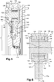
- the cam follower 124 is fixed to the primary flywheel by the cylindrical rod 122.
- This rod comprises, on the side of the secondary flywheel, a shoulder 125.
- the roller 121 is rotatably mounted around the rod by means of rollers 131 arranged to roll between an inner raceway 132 and an outer raceway 133.
- the inner raceway 132 is for example formed on a spacer 134 mounted around the rod 122.
- the spacer bears against the primary flywheel, here via a support washer 135.
- Two washers 128 and 129 are respectively interposed between the shoulder 125 of the rod 122 and the roller 121, and between the bearing washer 135 and the roller 121
- the two washers 128 and 129 axially define an interior bearing space in which the rollers 131 are arranged.
- the washers 128 and 129 are arranged axially on either side of the raceways 132 and 133. These washers are threaded around the inner raceway 132.
- Two shoulders are provided on each side of the roller to partially accommodate these washers 128 and 129.
- a game is left between the roller 121 and these washers 128 and 129.
- the cam follower provides a second function, namely to take the axial forces exerted on the blade.
- the cam follower 224 includes a roller 221 cooperating with an elastic blade 217a having a cam surface 220.
- the convex curved profile of the cam surface 220 is a circular arc
- the concave curved profile of the cam follower 224 is an arc of a circle.
- the difference with the previous embodiment is that the curved profile of the cam surface 220 has a radius R smaller than the radius (R + X) of the curve profile of the cam follower.
- the damper is arranged for the cam follower 224 and the cam surface 220 to contact the extremum E1.
- This damper is arranged so that the cam follower 224 and the cam surface 220 come into contact substantially on the extremum E2, especially in the absence of axial loads.
- the extremum E2 of the curved profile of the cam follower and the extremum E1 of the curved profile of the cam surface are on the contact area between the cam follower and the cam surface.
- the curved profile of the cam surface 320 is concave. In other words, the cam surface is dug into blade 317.
- the concave cam surface 320 cooperates with the roller 321 of the cam follower 324 which has a convex curved profile oriented towards the cam surface 320, so that torque transmission between the cam surface 320 and the cam follower 324 is performed via the concave curved profile of the cam surface within the concavity of the cam surface 320.
- the roller 321 has a convex profile periphery, this convex profile being directed towards the outside of the roller.
- the concave curved profile of the cam surface 320 is a circular arc and the convex curved profile of the roller 321 of the cam follower 324 is an arc of a circle.
- the curved profile of the cam surface 320 has a radius (R + X) greater than the radius R of the curved profile of the roller 321 of the cam follower 324.
- the damper is arranged for the cam follower 324 and the cam surface 320 to contact the extremum E1.
- This damper is arranged so that the cam follower 324 and the cam surface 320 come into substantially contact with the extremum E2, especially in the absence of axial loads.
- these two spokes could be substantially equal to prevent axial displacement between the cam follower and the blade.
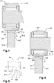
- the curved profile of the cam surface has a circular arc of radius R extending over the entire thickness of the blade 417.
- the damper is arranged so that the cam follower 424 and the cam surface 420 contact the extremum E1 of the arc.
- the Hertz H pressure curve seen by the roller 421 is shown. It can be seen that the stresses are located mainly in the center of the roller, which makes it possible to limit the edge effects, even in the event of tilting of the roller or blade, that is to say when the inclination of the follower cam and the cam surface is changed.
- the curved profile of the cam surface 520 here has an ellipse portion.
- This portion of ellipse is a half ellipse that extends over the entire thickness of the blade 517.
- This portion of ellipse is convex, that is to say facing the cam follower 524.
- the half ellipse extends to the flanks 541 and 542 of the blade 517 and includes the rounded corners 551 and 552 of the blade 517.
- a uniform profile is obtained over the entire thickness of the blade. to effectively lower the stresses on the cam surface and on the corners of the blade.
- the curved profile of the cam follower 524 also includes an ellipse portion.
- the curved profile of the cam surface can be obtained by machining the blade.
- the cam surface 620 of the blade 617 has a convex profile.
- a roller not shown, having a straight or concave profile, can cooperate with this blade 617 to transmit torque.
- the blade 617 comprises at least two strips 661 and 662 stacked one on the other. These stacked lamellae 661 and 662 have substantially the same thickness. These strips come into contact via a junction plane PJ which is located mid thickness of the blade thus assembled. These slats were previously cut.
- the two strips each comprise a portion of the cam surface 620 'and 620 ", these two portions being, in a plane P comprising the axis of rotation (X) of the damper and containing a point of contact between the cam follower and the cam surface, symmetrical with respect to the junction plane PJ of the two lamellae 661 and 662.
- the curved profiles of the two cam surface portions 620 'and 620 can be obtained directly during the cutting of the lamellae 661 and 662 in the sheet metal. These two lamellae 661 and 662 can be cut out of one and the same sheet, the shape of the lamella one of the slats being the mirror of the other so that they can then be assembled one against the other on either side of the junction plane PJ.
- the curved profile 620 of the cam surface may comprise a straight portion D, the remainder of the profile being curved.
- the curved profile can thus be achieved thanks to the clearance of the cutting tool.
- the straight portion D is formed by two straight portions D1 and D2 present on each strip 661 and 662. This straight portion is substantially parallel to the axis of rotation X. The extremum E1 of the curved profile of the cam surface 620 is arranged on this straight portion D.
- junction plane PJ of the two lamellae intersects the straight portion D.
- the junction plane PJ is a plane of symmetry for this straight portion D.
- the curved profile of the cam surface 720 is concave and has a central straight portion D extending on either side of the plane of symmetry PJ.
- a roller not shown, having a convex curved profile, can cooperate with this blade 717 to transmit torque.
- the blade 717 is formed with two lamellae 761 and 762 cut from a sheet and then assembled on either side of the junction plane, also plane of symmetry, PJ.
- Each lamella has a cam surface portion 720 'and 720 "each having a straight portion D1 and D2.
- curved profiles of the other embodiments described above can also, if desired, comprise a small straight portion arranged on a portion of the curved profile, for example extending over 10% or 20% of the curved profile.
- the right portion of the curved profile extends over less than 50% of this curved profile, here about 30% of the profile.
- the straight portion of the curved profile extends less than 50% of the thickness of the blade, here about 30% of the thickness of the blade.
- This method of manufacturing the blade can be applied to each of the curved profiles presented above.
- torsion damper in the context of a double damping flywheel, but such a torsion damper can be installed on any suitable device.
- torsion dampers can equip the clutch friction, in the case of a manual or robotic transmission, or the locking clutches, also called “lock-up” clutches, equipping the hydraulic coupling devices, in the case of an automatic transmission.
Landscapes
- Engineering & Computer Science (AREA)
- General Engineering & Computer Science (AREA)
- Physics & Mathematics (AREA)
- Acoustics & Sound (AREA)
- Aviation & Aerospace Engineering (AREA)
- Mechanical Engineering (AREA)
- Mechanical Operated Clutches (AREA)
- Fluid-Damping Devices (AREA)
- Gears, Cams (AREA)
Description
L'invention se rapporte à un amortisseur de torsion destiné à équiper un dispositif de transmission de couple. L'invention se rapporte plus particulièrement au domaine des transmissions pour véhicule automobile, l'invention étant destinée à transmettre le couple moteur entre le moteur et les roues du véhicule. Cet amortisseur peut être appliqué aussi bien à un dispositif de transmission pour automobile à boite manuelle, tel qu'un disque de friction amorti ou un double volant amortisseur, ainsi qu'à un dispositif de transmission pour automobile à boite automatique, tel qu'un convertisseur de couple ou lock-up.The invention relates to a torsion damper for equipping a torque transmission device. The invention relates more particularly to the field of transmissions for a motor vehicle, the invention being intended to transmit the engine torque between the engine and the wheels of the vehicle. This damper can be applied to a transmission device for a manual gearbox automobile, such as a damped friction disc or a double damping flywheel, as well as to a transmission device for an automobile with an automatic gearbox, such as a gearbox. torque converter or lock-up.
On connait des amortisseurs de torsion dont les éléments d'entrée et de sortie sont couplés en rotation par des moyens d'amortissement permettant de transmettre un couple et d'amortir les acyclismes de rotation. Les moyens d'amortissement sont généralement des ressorts hélicoïdaux, cintrés, disposés, de façon circonférentielle, dans une chambre annulaire, étanche, qui est formée entre les éléments d'entrée et de sortie.Torsional dampers are known whose input and output elements are coupled in rotation by damping means for transmitting a torque and damping rotation acyclisms. The damping means are generally helical, bent, circumferentially disposed springs in an annular, sealed chamber which is formed between the input and output members.
L'amortissement proposé par ces amortisseurs n'est pas tout à fait satisfaisant, notamment en raison des frottements importants, et il a été proposé également de réaliser des amortisseurs de torsion à lame, comme cela est décrit dans le document
On connait aussi l'amortisseur à lame du document
L'invention améliore les solutions de l'art antérieur et propose un amortisseur de torsion à lame élastique optimisé, et dont la résistance des lames et des suiveurs de came est améliorée.The invention improves the prior art solutions and provides an optimized elastic blade torsion damper, and whose blade and cam follower resistance is improved.
L'invention concerne ainsi un amortisseur de torsion pour dispositif de transmission de couple, notamment pour automobile, en particulier pour un dispositif d'embrayage, l'amortisseur comportant :
- un premier élément,
- un second élément mobile en rotation par rapport au premier élément autour d'un axe de rotation X,
- un organe de transmission porté par le second élément, cet organe de transmission comportant une lame élastique agencée pour fléchir pour transmettre un couple de rotation entre ces deux éléments, la flexion de la lame élastique étant accompagnée d'une rotation relative des premier et second éléments selon l'axe de rotation X pour amortir les acyclismes de rotation entre le premier élément et le second élément, la lame élastique comportant une surface de came,
- un suiveur de came porté par le premier élément et agencé pour se déplacer sur la surface de came,
- a first element,
- a second element movable in rotation with respect to the first element about an axis of rotation X,
- a transmission member carried by the second element, this transmission member comprising an elastic blade arranged to flex to transmit a torque between these two elements, the bending of the elastic blade being accompanied by a relative rotation of the first and second elements along the axis of rotation X to dampen the rotation acyclisms between the first element and the second element, the elastic blade having a cam surface,
- a cam follower carried by the first member and arranged to move on the cam surface;
Ainsi, grâce à ce profil courbe, les contraintes de Hertz générées par le roulement du suiveur de came sur la surface de came peuvent être maitrisées. Il est possible d'éviter des accumulations excessives de contraintes, notamment sur des zones sensibles de la lame et du suiveur de came, notamment en cas de basculement relatif entre le lame et le suiveur de came, c'est-à-dire lorsque l'inclinaison du suiveur de came et de la lame évolue. La lame et le suiveur de came deviennent ainsi plus résistants. Aussi, le profil courbe est agencé pour éloigner les concentrations de contraintes des coins de la lame. On entend par coins les zones de jonction entre la surface de came et les flancs de la lame.Thus, thanks to this curved profile, the Hertz stresses generated by the rolling of the cam follower on the cam surface can be mastered. It is possible to avoid excessive accumulation of stresses, especially on sensitive areas of the blade and the cam follower, especially in the case of relative tilting between the blade and the cam follower, that is to say when tilting of the cam follower and the blade is changing. The blade and the cam follower become more resistant. Also, the curved profile is arranged to move the stress concentrations away from the corners of the blade. Corner means the junction areas between the cam surface and the flanks of the blade.
Selon d'autres modes de réalisation avantageux, l'amortisseur de torsion peut présenter une ou plusieurs des caractéristiques suivantes :
- le profil courbe de la surface de came s'étend sur toute l'épaisseur de la lame.
- le profil courbe de la surface de came présente un extremum et l'amortisseur est agencé pour que cet extremum soit sur la zone de contact entre la surface de came et le suiveur de came.
- l'extremum est éloigné des coins de la lame. La distance séparant l'extremum du coin de lame le plus proche est supérieur au quart de l'épaisseur de la lame, notamment supérieur au tiers de l'épaisseur de la lame. Ainsi, une grande partie des contraintes de Hertz sont réparties au voisinage de l'extremum. Ainsi, en comparaison avec les solutions de l'art antérieur dans lesquelles les profils de la surface de came et du suiveur de came sont totalement droits, on empêche l'apparition de zones de concentrations excessives de contraintes, notamment dans les coins de la lame, notamment lorsque des légers phénomènes de basculement interviennent et que l'inclinaison entre le suiveur de came et la surface de came est modifiée.
- l'extremum est situé sensiblement à mi-épaisseur de la lame.
- le profil courbe de la surface de came présente une symétrie par un plan perpendiculaire à l'axe de rotation et passant par la mi épaisseur de la lame.
- le profil courbe de la surface de came comporte un arc de cercle. Ainsi, le profil courbe est facile à réaliser.
- cet arc de cercle présente une ouverture angulaire inférieure ou égale à 180°, notamment inférieure ou égale à 90°, en particulier inférieure ou égale à 45°, par exemple comprise entre 5° et 20°.
- la valeur du rayon de cet arc de cercle est par exemple comprise entre le quart et les trois quarts de la distance radiale séparant l'axe de rotation de l'amortisseur du suiveur de came, de préférence entre le tiers et les deux tiers de la distance radiale séparant l'axe de rotation de l'amortisseur du suiveur de came, par exemple sensiblement égale à la moitié de la distance radiale séparant l'axe de rotation de l'amortisseur du suiveur de came. Ainsi, pression Hertzienne est optimisée.
- l'arc de cercle du profil courbe de la surface de came s'étend sur toute l'épaisseur de la lame.
- le profil courbe de la surface de came est dépourvu d'arête vive.
- la surface de came présente, sur toute son étendue circonférentielle autour de l'axe de rotation, ledit profil courbe.
- dans un plan comprenant l'axe de rotation de l'amortisseur et contenant un point de contact entre le suiveur de came et la surface de came, le suiveur de came présente un profil courbe.
- le profil courbe du suiveur de came présente également un extremum et l'amortisseur est agencé pour que cet extremum soit sur la zone de contact entre la surface de came et le suiveur de came.
- l'extremum du suiveur de came est situé sensiblement à mi-épaisseur du suiveur de came.
- le profil courbe du suiveur de came comporte un arc de cercle.
- l'arc de cercle du profil courbe du suiveur de came s'étend sur toute l'épaisseur du suiveur de came.
- les profils courbes du suiveur de came et de la surface de came présentent des formes permettant leur emboitement. Ainsi, il est possible de limiter le débattement axial entre le suiveur de came et la lame.
- l'un du suiveur de came et de la surface de came présente un profil courbe concave, la concavité étant orientée vers l'autre du suiveur de came et de la surface de came qui présente un profil courbe convexe, le profil courbe convexe s'engageant à l'intérieur du profil courbe concave.
- l'extremum du profil courbe du suiveur de came et l'extremum du profil courbe de la surface de came sont sur la zone de contact entre le suiveur de came et la surface de came.
- les deux profils courbes présentent des formes géométriques complémentaires.
- les deux profils courbes présentent des arcs de cercle sensiblement de même rayon.
- le profil courbe concave présente un arc de cercle dont le rayon est supérieur au rayon de l'arc de cercle du profil courbe convexe. Ainsi, on écarte la zone de contact entre le suiveur de came et la surface de came des coins de la lame. De plus, un léger déplacement relatif axial entre le suiveur de came et la surface de came est possible en cas d'efforts axiaux sur la lame. Ceci permet de limiter l'apparition et la transmission excessive de contraintes dues à des charges axiales reçues par les lames.
- le rayon de l'arc de cercle du profil courbe concave est au plus 50% plus grand que le rayon de l'arc de cercle du profil courbe convexe, notamment au plus 30% plus grand que le rayon de l'arc de cercle du profil courbe convexe, par exemple environ 10% plus grand que le rayon de l'arc de cercle du profil courbe convexe.
- le suiveur de came comporte un galet agencé pour rouler sur la surface de came. Ainsi, grâce à une meilleure distribution des contraintes de Hertz, le roulement du galet est amélioré.
- le galet est monté mobile en rotation sur le premier élément, autour d'un axe sensiblement parallèle à l'axe de rotation de l'amortisseur,
- le profil courbe du suiveur de came est présent sur tout le pourtour du galet.
- le profil courbe de la surface de came est convexe. Autrement dit, la surface de came est bombée. Ainsi, il est possible d'optimiser la pression Hertzienne provenant du contact entre la lame et le suiveur de came et d'éviter les effets de bord, quelque soit la géométrie du suiveur de came dont le profil selon le plan P peut, par exemple, rester droit.
- lorsque le profil courbe de la surface de came est convexe, la surface de came coopère avec le suiveur de came présentant un profil courbe concave orienté en direction de la surface de came, de sorte que la transmission du couple entre la surface de came et le suiveur de came peut être effectuée via le profil courbe convexe de la surface de came à l'intérieur de la concavité du suiveur de came.
- selon ce mode de réalisation, lorsque le suiveur de came comporte un galet, il présente un pourtour présentant un profil concave, cette concavité étant ouverte vers l'extérieur du galet.
- le profil courbe convexe de la surface de came est un arc de cercle et le profil courbe concave du suiveur de came est un arc de cercle, le profil courbe convexe de la surface de came présentant un rayon inférieur ou égal à celui du profil courbe concave du suiveur de came.
- lorsque profil courbe convexe de la surface de came est un arc de cercle, et lorsque le profil courbe concave du suiveur de came est un arc de cercle, le profil courbe de la surface de came présente un rayon inférieur au rayon du profil courbe du suiveur de came. Ainsi, la pression Hertzienne est optimisée et un léger déplacement relatif axial entre le suiveur de came et la surface de came est possible en cas d'efforts axiaux sur la lame. Ceci permet de limiter l'apparition et la transmission excessives de contraintes dues à des charges axiales reçues ponctuellement par les lames.
- lorsque profil courbe convexe de la surface de came est un arc de cercle, et lorsque le profil courbe concave du suiveur de came est un arc de cercle, le profil courbe de la surface de came présente, si on le souhaite, un rayon sensiblement égal au rayon du profil courbe du suiveur de came. Ainsi, on évite, si on le souhaite, les décalages axiaux entre le suiveur de came et la lame.
- selon un autre mode de réalisation, le profil courbe de la surface de came est concave. Autrement dit, la surface de came est creusée dans lame.
- lorsque le profil courbe de la surface de came est concave, la surface de came coopère avec le suiveur de came qui présente un profil courbe convexe orienté en direction de la surface de came, de sorte que la transmission du couple entre la surface de came et le suiveur de came peut être effectuée via le profil courbe concave de la surface de came à l'intérieur de la concavité de la surface de came.
- selon ce mode de réalisation, lorsque le suiveur de came comporte un galet, il présente un pourtour présentant un profil convexe, ce profil convexe étant dirigé vers l'extérieur du galet.
- lorsque le profil courbe concave de la surface de came est un arc de cercle, et lorsque le profil courbe convexe du suiveur de came est un arc de cercle, le profil courbe de la surface de came présente un rayon supérieur ou égal à celui du profil courbe du suiveur de came.
- lorsque profil courbe concave de la surface de came est un arc de cercle, et lorsque le profil courbe convexe du suiveur de came est un arc de cercle, le profil courbe de la surface de came présente un rayon supérieur à celui du profil courbe du suiveur de came. Ainsi, un léger décalage axial reste possible entre le suiveur de came et la surface de came dans le cas où les lames sont sollicitées axialement.
- si on le souhaite, lorsque le profil courbe concave de la surface de came est un arc de cercle, et lorsque le profil courbe convexe du suiveur de came est un arc de cercle, le profil courbe de la surface de came présente un rayon sensiblement égal à celui du profil courbe du suiveur de came. Ainsi, on peut, si on le souhaite, empêcher le débattement axial entre le suiveur de came et la lame.
- selon un mode de réalisation de l'invention, dans un plan comprenant l'axe de rotation (X) de l'amortisseur et contenant un point de contact entre le suiveur de came et la surface de came, le suiveur de came présente un profil droit et la surface de came présente un profil courbe convexe. Ainsi, cette solution offre un compromis intéressant car, sans augmenter le cout de fabrication du suiveur de came, notamment lorsqu'il comporte un galet roulant sur la surface de came, la pression Hertzienne est optimisée par rapport aux solutions de l'état de la technique dans lesquelles le suiveur de came présente un profil droit roulant sur une surface de came au profil droit.
- si on le souhaite, le profil courbe de la surface de came est obtenu par usinage de la lame.
- si on le souhaite, la lame comporte au moins deux lamelles empilées l'une sur l'autre.
- les lamelles empilées présentent sensiblement la même épaisseur.
- la lame comporte deux lamelles qui viennent en contact via un plan de jonction.
- le plan de jonction est situé à mi épaisseur de la lame ainsi assemblée.
- l'extremum du profil courbe de surface de came est situé sur le plan de jonction des deux lamelles.
- les deux lamelles comportent chacune une portion de surface de came, ces deux portions étant symétriques par rapport au plan de jonction des deux lamelles.
- Si on le souhaite, le profil courbe de la surface de came comporte une portion d'ellipse
- la portion d'ellipse sur laquelle est formée la surface de came s'étend sur toute l'épaisseur de la lame.
- la portion d'ellipse est une demi ellipse.
- la portion d'ellipse de la surface de came est convexe, c'est-à-dire tournée vers le suiveur de came.
- la demi-ellipse comporte un grand rayon sur lequel est formée la surface de came et deux petits rayon sur lesquels sont formés les coins de la lame reliant chaque flanc à la surface de came. Ainsi, en obtient sur toute l'épaisseur de la lame un profil homogène et la répartition des contraintes est optimisée. Cela permet d'obtenir de façon très homogène une surface de came courbe et deux chanfreins arrondis.
- Si on le souhaite, le profil courbe du suiveur de came comporte une portion d'ellipse.
- les premiers et seconds éléments sont entrainés en rotation autour de l'axe X.
- les premier et second éléments occupent une position angulaire relative de repos en l'absence de transmission de couple,
- l'élasticité de la lame permet de maintenir le galet au contact de la surface de came.
- la lame élastique et le suiveur de came sont agencés de telle sorte qu'en fonctionnement, le suiveur de came exerce un effort de flexion sur la lame et produisant en réaction une force de réaction de la lame sur le suiveur de came apte à rappeler les premier et second éléments vers la position angulaire de repos.
- cette force de réaction est une force de rappel élastique exercée par la lame flexible sur le suiveur de came en réaction à la déformation élastique de la lame flexible.
- la force de réaction est une force de rappel élastique exercée uniquement par la lame flexible sur le suiveur de came en réaction à la déformation élastique de la lame flexible.
- la flexion de la lame est accompagnée d'une rotation relative entre les premier et second éléments.
- la lame élastique comporte une zone d'extrémité libre et l'amortisseur est agencé de sorte que cette zone d'extrémité libre se déplace radialement par rapport à l'axe de rotation de l'amortisseur lorsque le suiveur de came fait fléchir la lame. Autrement dit, la distance radiale séparant l'axe de rotation de ladite zone d'extrémité distale libre varie en fonction du débattement angulaire entre le premier et le second élément.
- la zone d'extrémité libre prolonge circonférentiellement la surface de came.
- le suiveur de came comporte un galet monté mobile en rotation sur lui-même sur le premier élément
- selon un autre mode de réalisation non représenté, le suiveur de came est un corps roulant mobile en rotation par rapport aux premier et second éléments. Le corps roulant se déplace d'une part sur la lame élastique portée par le second élément, notamment en roulant et en la faisant fléchir, d'autre part sur le premier élément. De préférence, en roulant sur la lame élastique portée par le second élément, le corps roulant accomplit un trajet curviligne sur le premier élément sur au moins un secteur angulaire prédéterminé, notamment en roulant.
- la lame est agencée pour se déformer dans un plan perpendiculaire à l'axe de rotation X.
- l'organe de transmission comporte deux lames agencées de façon symétrique par rapport à l'axe de rotation.
- l'organe de transmission comporte plusieurs lames régulièrement disposées autour de l'axe de rotation.
- Si on le souhaite, les lames sont agencées autour d'un corps annulaire
- le cas échéant, l'organe de transmission avec ses lames sont formés d'un seul tenant sur une même pièce, cette pièce pouvant elle-même être formée par un empilement de lamelles.
- en variante, l'amortisseur comporte au moins deux organes de transmission agencés par exemple de façon symétrique par rapport à l'axe de rotation.
- l'amortisseur comporte plusieurs organes de transmission régulièrement disposées autour de l'axe de rotation.
- chaque organe de transmission comporte une seule lame.
- l'organe de transmission comporte une portion de fixation fixée sur le second élément et une portion flexible comprenant la lame élastique.
- de préférence, la portion de fixation reste fixe, autrement dit elle ne fléchit pas, lorsque les premier et second éléments tournent l'un par rapport à l'autre.
- La surface de came et la portion de fixation sont reliées par un coude.
- La lame n'est liée au second élément que par l'intermédiaire de sa portion de fixation.
- l'amortisseur comporte deux lames élastiquement déformables portées par le second élément et l'amortisseur comporte deux suiveurs de came portés le premier élément, les suiveurs de came étant respectivement agencés pour coopérer avec l'une et l'autre des deux lames élastiquement déformables.
- les lames élastiquement déformables sont symétriques par rapport à l'axe de rotation.
- le galet est monté mobile en rotation sur le premier élément, par l'intermédiaire d'un palier à roulement.
- la surface de came s'étend circonférentiellement autour de l'axe de rotation X.
- la surface de came comporte une position neutre occupée par le suiveur de came lorsqu'aucun couple n'est transmis par l'amortisseur.
- lorsque les premier et second éléments sont en position angulaire de repos, le suiveur de came est sur la position neutre de la surface de came.
- l'épaisseur du suiveur de came est plus grande que l'épaisseur de la surface de came.
- L'épaisseur du galet est plus grande que l'épaisseur de la lame
- Le profil courbe de la surface de came peut comporter une portion droite.
- Cette portion droite est sensiblement parallèle à l'axe de rotation de l'amortisseur
- L'extremum du profil courbe de la surface de came est agencé sur cette portion droite.
- Le plan de jonction des deux lamelles coupe la portion droite.
- Le plan de jonction est un plan de symétrie pour la portion droite.
- Dans un plan comprenant l'axe de rotation X de l'amortisseur et contenant un point de contact entre le suiveur de came et la surface de came, la portion droite du profil courbe s'étend sur moins de 70% de ce profil, en particulier moins 50% de ce profil courbe, par exemple sur moins de 30% , notamment moins de 10%.
- Dans un plan comprenant l'axe de rotation X de l'amortisseur et contenant un point de contact entre le suiveur de came et la surface de came, la portion droite s'étend sur moins de 70% de ce profil, en particulier moins 50% de l'épaisseur de la lame, par exemple sur moins de 30% de l'épaisseur de la lame, notamment moins de 10%.
- Dans un plan comprenant l'axe de rotation X de l'amortisseur et contenant un point de contact entre le suiveur de came et la surface de came, le profil de la surface de came de la lame est dépourvu de portion droite s'étendant sur plus de 30% de ce profil, en particulier sur plus de 50% de ce profil, notamment sur plus de 70% de ce profil.
- Dans un plan comprenant l'axe de rotation X de l'amortisseur et contenant un point de contact entre le suiveur de came et la surface de came, le profil de la surface de came de la lame est dépourvu de portion droite s'étendant sur plus de 30% de l'épaisseur de la lame, en particulier sur plus de 50% de l'épaisseur de la lame, notamment sur plus de 70% de l'épaisseur de la lame.
- La dimension axialle de la portion droite est plus petite que la moitié de la dimension axiale (épaisseur) de la lame.
- the curved profile of the cam surface extends over the entire thickness of the blade.
- the curved profile of the cam surface has an extremum and the damper is arranged so that this extremum is on the contact area between the cam surface and the cam follower.
- the extremum is far away from the corners of the blade. The distance separating the extremum from the nearest blade wedge is greater than a quarter of the thickness of the blade, in particular greater than one third of the thickness of the blade. Thus, a large part of Hertz's constraints are distributed around the extremum. Thus, in comparison with the solutions of the prior art in which the profiles of the cam surface and the cam follower are completely straight, it prevents the appearance of zones of excessive stress concentrations, especially in the corners of the blade , especially when slight rocking phenomena occur and the inclination between the cam follower and the cam surface is changed.
- the extremum is located substantially mid-thickness of the blade.
- the curved profile of the cam surface has a symmetry in a plane perpendicular to the axis of rotation and passing through the mid thickness of the blade.
- the curved profile of the cam surface has an arc. Thus, the curved profile is easy to achieve.
- this arc has an angular aperture less than or equal to 180 °, in particular less than or equal to 90 °, in particular less than or equal to 45 °, for example between 5 ° and 20 °.
- the value of the radius of this arc is for example between one quarter and three quarters of the radial distance between the axis of rotation of the damper of the cam follower, preferably between one third and two thirds of the radial distance between the axis of rotation of the damper of the cam follower, for example substantially equal to half the radial distance between the axis of rotation of the damper of the cam follower. Thus, Hertzian pressure is optimized.
- the arc of the curved profile of the cam surface extends over the entire thickness of the blade.
- the curved profile of the cam surface is devoid of sharp edges.
- the cam surface has, throughout its circumferential extent around the axis of rotation, said curved profile.
- in a plane comprising the axis of rotation of the damper and containing a point of contact between the cam follower and the cam surface, the cam follower has a curved profile.
- the curved profile of the cam follower also has an extremum and the damper is arranged so that this extremum is on the contact area between the cam surface and the cam follower.
- the extremum of the cam follower is located substantially mid-thickness of the cam follower.
- the curved profile of the cam follower has an arc.
- the arc of the curved profile of the cam follower extends over the entire thickness of the cam follower.
- the curved profiles of the cam follower and the cam surface have shapes allowing them to be interlocked. Thus, it is possible to limit the axial displacement between the cam follower and the blade.
- one of the cam follower and the cam surface has a concave curved profile, the concavity facing the other of the cam follower and the cam surface having a convex curved profile, the convex curved profile being engaging inside the concave curved profile.
- the extremum of the curved profile of the cam follower and the extremum of the curved profile of the cam surface are on the contact area between the cam follower and the cam surface.
- the two curved profiles have complementary geometric shapes.
- the two curved profiles have arcs of substantially the same radius radius.
- the concave curved profile has an arc whose radius is greater than the radius of the arc of the curved convex profile. So, we away from the contact area between the cam follower and the cam surface of the corners of the blade. In addition, a slight axial relative displacement between the cam follower and the cam surface is possible in the case of axial forces on the blade. This limits the occurrence and excessive transmission of stresses due to axial loads received by the blades.
- the radius of the arc of the concave curved profile is at most 50% greater than the radius of the arc of the curved convex profile, in particular at most 30% greater than the radius of the arc of the convex curve profile, for example about 10% larger than the radius of the arc of the convex curve profile.
- the cam follower comprises a roller arranged to roll on the cam surface. Thus, thanks to a better distribution of the stresses of Hertz, the rolling of the roller is improved.
- the roller is rotatably mounted on the first element, about an axis substantially parallel to the axis of rotation of the damper,
- the curved profile of the cam follower is present all around the roller.
- the curved profile of the cam surface is convex. In other words, the cam surface is curved. Thus, it is possible to optimize the air pressure coming from the contact between the blade and the cam follower and to avoid the edge effects, whatever the geometry of the cam follower whose profile according to the plane P can, for example , stay upright.
- when the curved profile of the cam surface is convex, the cam surface cooperates with the cam follower having a concave curved profile oriented towards the cam surface, so that torque transmission between the cam surface and the cam surface is Cam follower can be performed via the convex curve profile of the cam surface within the concavity of the cam follower.
- according to this embodiment, when the cam follower comprises a roller, it has a periphery having a concave profile, this concavity being open towards the outside of the roller.
- the convex curved profile of the cam surface is an arc and the concave curved profile of the cam follower is an arc, the convex curved profile of the cam surface having a radius less than or equal to that of the concave curved profile the cam follower.
- when the convex curve profile of the cam surface is a circular arc, and when the concave curved profile of the cam follower is a circular arc, the curved profile of the cam surface has a radius smaller than the radius of the curved profile of the follower of cam. Thus, the Hertzian pressure is optimized and a slight axial relative displacement between the cam follower and the cam surface is possible in the case of axial forces on the blade. This makes it possible to limit the excessive appearance and transmission of stresses due to axial loads received punctually by the blades.
- when the convex curve profile of the cam surface is a circular arc, and when the concave curve profile of the cam follower is a circular arc, the curved profile of the cam surface has, if desired, a substantially equal radius to the radius of the curved profile of the cam follower. Thus, the axial offsets between the cam follower and the blade are avoided, if desired.
- in another embodiment, the curved profile of the cam surface is concave. In other words, the cam surface is dug into the blade.
- when the curved profile of the cam surface is concave, the cam surface cooperates with the cam follower which has a convex curved profile oriented toward the cam surface, so that torque transmission between the cam surface and the cam follower may be effected via the concave curved profile of the cam surface within the concavity of the cam surface.
- according to this embodiment, when the cam follower comprises a roller, it has a periphery having a convex profile, the convex profile being directed towards the outside of the roller.
- when the concave curved profile of the cam surface is an arc, and when the convex curved profile of the cam follower is an arc, the curved profile of the cam surface has a radius greater than or equal to that of the profile curve of the cam follower.
- when the concave curve profile of the cam surface is a circular arc, and when the convex curve profile of the cam follower is a circular arc, the curved profile of the cam surface has a radius greater than that of the curved profile of the follower of cam. Thus, a slight axial shift remains possible between the cam follower and the cam surface in the case where the blades are axially biased.
- if desired, when the concave curved profile of the cam surface is a circular arc, and when the convex curved profile of the cam follower is a circular arc, the curved profile of the cam surface has a substantially equal radius to that of the curve profile of the cam follower. Thus, it is possible, if desired, to prevent axial displacement between the cam follower and the blade.
- according to one embodiment of the invention, in a plane comprising the axis of rotation (X) of the damper and containing a point of contact between the cam follower and the cam surface, the cam follower has a profile right and the cam surface has a convex curved profile. Thus, this solution offers an interesting compromise because, without increasing the manufacturing cost of the cam follower, especially when it comprises a roller rolling on the cam surface, the air pressure is optimized compared to the solutions of the state of the cam. in which the cam follower has a straight profile rolling on a right profile cam surface.
- if desired, the curved profile of the cam surface is obtained by machining the blade.
- if desired, the blade has at least two lamellae stacked one on top of the other.
- the stacked lamellae have substantially the same thickness.
- the blade comprises two lamellae which come into contact via a junction plane.
- the junction plane is located mid thickness of the blade thus assembled.
- the extremum of the curved cam surface profile is located on the joining plane of the two lamellae.
- the two strips each comprise a cam surface portion, these two portions being symmetrical with respect to the junction plane of the two lamellae.
- If desired, the curved profile of the cam surface has an ellipse portion
- the ellipse portion on which the cam surface is formed extends over the entire thickness of the blade.
- the ellipse portion is a half ellipse.
- the ellipse portion of the cam surface is convex, i.e. facing the cam follower.
- the half-ellipse has a large radius on which is formed the cam surface and two small radius on which are formed the corners of the blade connecting each side to the cam surface. Thus, the entire thickness of the blade is obtained a homogeneous profile and the distribution of constraints is optimized. This makes it possible to obtain in a very homogeneous manner a curved cam surface and two rounded chamfers.
- If desired, the curved profile of the cam follower has an ellipse portion.
- the first and second elements are rotated about the X axis.
- the first and second elements occupy a relative angular position of rest in the absence of torque transmission,
- the elasticity of the blade keeps the roller in contact with the cam surface.
- the resilient blade and the cam follower are arranged such that in operation the cam follower exerts a bending force on the blade and in reaction produces a reaction force of the blade on the cam follower adapted to recall the first and second elements to the angular position of rest.
- this reaction force is an elastic restoring force exerted by the flexible blade on the cam follower in response to the elastic deformation of the flexible blade.
- the reaction force is an elastic restoring force exerted solely by the flexible blade on the cam follower in response to the elastic deformation of the flexible blade.
- the bending of the blade is accompanied by a relative rotation between the first and second elements.
- the resilient blade has a free end region and the damper is arranged such that this free end region moves radially relative to the axis of rotation of the damper when the cam follower bends the blade. In other words, the radial distance separating the axis of rotation from said free distal end zone varies as a function of the angular displacement between the first and the second element.
- the free end zone circumferentially extends the cam surface.
- the cam follower comprises a roller mounted to rotate on itself on the first element
- according to another embodiment not shown, the cam follower is a rolling body movable in rotation relative to the first and second elements. The rolling body moves on the one hand on the elastic blade carried by the second element, including rolling and bending, on the other hand on the first element. Preferably, by rolling on the elastic blade carried by the second element, the rolling body accomplishes a curvilinear path on the first element on at least one predetermined angular sector, including rolling.
- the blade is arranged to deform in a plane perpendicular to the axis of rotation X.
- the transmission member comprises two blades arranged symmetrically with respect to the axis of rotation.
- the transmission member comprises a plurality of blades regularly arranged around the axis of rotation.
- If desired, the blades are arranged around a ring body
- if necessary, the transmission member with its blades are formed integrally on the same part, this part itself can be formed by a stack of lamellae.
- alternatively, the damper comprises at least two transmission members arranged for example symmetrically with respect to the axis of rotation.
- the damper comprises a plurality of transmission members regularly arranged around the axis of rotation.
- each transmission member comprises a single blade.
- the transmission member comprises a fixing portion fixed on the second element and a flexible portion comprising the elastic blade.
- preferably, the attachment portion remains fixed, that is, it does not flex when the first and second elements rotate relative to each other.
- The cam surface and the attachment portion are connected by a bend.
- The blade is bonded to the second element only through its fixing portion.
- the damper comprises two elastically deformable blades carried by the second element and the damper comprises two cam followers carried the first element, the cam followers being respectively arranged to cooperate with one and the other of the two elastically deformable blades.
- the elastically deformable blades are symmetrical with respect to the axis of rotation.
- the roller is rotatably mounted on the first element, by means of a rolling bearing.
- the cam surface extends circumferentially around the axis of rotation X.
- the cam surface has a neutral position occupied by the cam follower when no torque is transmitted by the damper.
- when the first and second members are in the angular position of rest, the cam follower is in the neutral position of the cam surface.
- the thickness of the cam follower is larger than the thickness of the cam surface.
- The thickness of the roller is greater than the thickness of the blade
- The curved profile of the cam surface may comprise a straight portion.
- This straight portion is substantially parallel to the axis of rotation of the damper
- The extremum of the curved profile of the cam surface is arranged on this straight portion.
- The plane of junction of the two lamellae cuts the right portion.
- The junction plane is a plane of symmetry for the right portion.
- In a plane comprising the axis of rotation X of the damper and containing a point of contact between the cam follower and the cam surface, the straight portion of the curved profile extends over less than 70% of this profile, especially less than 50% of this curved profile, for example less than 30%, especially less than 10%.
- In a plane comprising the axis of rotation X of the damper and containing a point of contact between the cam follower and the cam surface, the straight portion extends over less than 70% of this profile, in particular less than 50%. % of the thickness of the blade, for example less than 30% of the thickness of the blade, especially less than 10%.
- In a plane comprising the axis of rotation X of the damper and containing a point of contact between the cam follower and the cam surface, the profile of the cam surface of the blade is devoid of straight portion extending over more than 30% of this profile, especially over more than 50% of this profile, including more than 70% of this profile.
- In a plane comprising the axis of rotation X of the damper and containing a point of contact between the cam follower and the cam surface, the profile of the cam surface of the blade is devoid of straight portion extending over more than 30% of the thickness of the blade, in particular over more than 50% of the thickness of the blade, especially over more than 70% of the thickness of the blade.
- The axial dimension of the straight portion is smaller than half the axial dimension (thickness) of the blade.
L'amortisseur est un double volant amortisseur dans lequel le premier élément est formé par l'un des volants d'inertie primaire et secondaire et le second élément est formé par l'autre des volants d'inertie primaire et secondaire.The damper is a double damping flywheel in which the first element is formed by one of the primary and secondary flywheels and the second element is formed by the other primary and secondary flywheels.
L'invention porte également sur un amortisseur de torsion pour dispositif de transmission de couple, notamment pour automobile, en particulier pour un dispositif d'embrayage, l'amortisseur comportant :
- un premier élément,
- un second élément mobile en rotation par rapport au premier élément autour d'un axe de rotation X,
- un organe de transmission porté par le second élément, cet organe de transmission comportant une lame élastique agencée pour fléchir pour transmettre un couple de rotation entre ces deux éléments, la flexion de la lame élastique étant accompagnée d'une rotation relative des premier et second éléments selon l'axe de rotation X pour amortir les acyclismes de rotation entre le premier élément et le second élément, la lame élastique comportant une surface de came,
- un suiveur de came porté par le premier élément, le suiveur de came comportant un galet monté mobile en rotation sur le premier élément et agencé pour rouler sur la surface de came,
- a first element,
- a second element movable in rotation with respect to the first element about an axis of rotation X,
- a transmission member carried by the second element, this transmission member comprising an elastic blade arranged to flex to transmit a torque between these two elements, the bending of the elastic blade being accompanied by a relative rotation of the first and second elements along the axis of rotation X to dampen the rotation acyclisms between the first element and the second element, the elastic blade having a cam surface,
- a cam follower carried by the first member, the follower having a roller rotatably mounted on the first member and arranged to roll on the cam surface;
Selon d'autres modes de réalisation avantageux, cet amortisseur de torsion peut présenter une ou plusieurs des caractéristiques suivantes :
- L'un parmi le galet et la surface de came comporte, dans un plan comprenant l'axe de rotation X de l'amortisseur et contenant un point de contact entre le suiveur de came et la surface de came, un profil convexe et l'autre parmi le galet et la surface de came comporte un profil concave.
- Le galet est monté mobile en rotation autour d'une tige. Cette tige s'étend de préférence parallèlement à l'axe de rotation de l'amortisseur.
- Le galet est disposé axialement entre deux rondelles de frottement, de façon à frotter sur l'une d'entre elles lorsque des efforts axiaux sont transmis par la lame au galet.
- Le galet comporte de chaque côté un épaulement logeant partiellement une rondelle de frottement.
- Le suiveur de came comporte des corps roulants tels que des billes ou des rouleaux agencés pour rouler entre une piste de roulement intérieure et une piste de roulement extérieure. Ainsi, en améliorant la répartition des contraintes de Hertz, l'usure de ces corps roulants est limitée.
- Les deux rondelles délimitent axialement un espace intérieur de roulement dans lequel sont agencés les corps roulants.
- Les rondelles sont disposées axialement de part et d'autre des pistes de roulement.
- Les rondelles sont enfilées autour de la piste de roulement intérieure.
- One of the roller and the cam surface includes, in a plane including the axis of rotation X of the damper and containing a point of contact between the cam follower and the cam surface, a convex profile and the another of the roller and the cam surface has a concave profile.
- The roller is rotatably mounted around a rod. This rod preferably extends parallel to the axis of rotation of the damper.
- The roller is disposed axially between two friction washers, so as to rub on one of them when axial forces are transmitted by the blade to the roller.
- The roller comprises on each side a shoulder partially housing a friction washer.
- The cam follower comprises rolling bodies such as balls or rollers arranged to roll between an inner raceway and a outer raceway. Thus, by improving the distribution of Hertz stresses, the wear of these rolling bodies is limited.
- The two washers axially define an interior bearing space in which the rolling bodies are arranged.
- The washers are arranged axially on either side of the raceways.
- The washers are threaded around the inner raceway.
L'invention concerne aussi un amortisseur de torsion pour dispositif de transmission de couple, notamment pour automobile, en particulier pour un dispositif d'embrayage, l'amortisseur comportant :
- un premier élément,
- un second élément mobile en rotation par rapport au premier élément autour d'un axe de rotation X,
- un organe de transmission porté par le second élément, cet organe de transmission comportant une lame élastique agencée pour fléchir pour transmettre un couple de rotation entre ces deux éléments, la flexion de la lame élastique étant accompagnée d'une rotation relative des premier et second éléments selon l'axe de rotation X pour amortir les acyclismes de rotation entre le premier élément et le second élément, la lame élastique comportant une surface de came,
- un suiveur de came porté par le premier élément et agencé pour se déplacer sur la surface de came,
- a first element,
- a second element movable in rotation with respect to the first element about an axis of rotation X,
- a transmission member carried by the second element, this transmission member comprising an elastic blade arranged to flex to transmit a torque between these two elements, the bending of the elastic blade being accompanied by a relative rotation of the first and second elements along the axis of rotation X to dampen the rotation acyclisms between the first element and the second element, the elastic blade having a cam surface,
- a cam follower carried by the first member and arranged to move on the cam surface;
Ainsi, avec un profil convexe orienté en direction du suiveur de came, il est possible d'optimiser la répartition des contraintes de Hertz et d'éviter une accumulation excessive de contraintes, notamment sur des zones sensibles de la lame et du suiveur de came. Il est en particulier possible d'éviter les effets de bords.Thus, with a convex profile oriented in the direction of the cam follower, it is possible to optimize the distribution of Hertz stresses and to avoid excessive accumulation of stresses, particularly on sensitive areas of the blade and the cam follower. In particular, it is possible to avoid edge effects.
Selon d'autres modes de réalisation avantageux, cet amortisseur de torsion peut présenter une ou plusieurs des caractéristiques suivantes :
- la surface de came présente, sur toute son étendue circonférentielle autour de l'axe de rotation, ledit profil convexe.
- Le suiveur de came comporte un galet agencé pour rouler sur la surface de came.
- Le suiveur de came présente, dans le plan comprenant l'axe de rotation X de l'amortisseur et contenant un point de contact entre le suiveur de came et la surface de came, un profil droit ou concave.
- Le profil droit ou concave du suiveur de came est formé sur le pourtour extérieur du galet.
- the cam surface has, over its entire circumferential extent around the axis of rotation, said convex profile.
- The cam follower has a roller arranged to roll on the cam surface.
- The cam follower has, in the plane comprising the axis of rotation X of the damper and containing a point of contact between the cam follower and the cam surface, a straight or concave profile.
- The straight or concave profile of the cam follower is formed on the outer periphery of the roller.
L'invention concerne aussi une lame tel que décrite ci-dessus, pour un amortisseur de torsion, pour dispositif de transmission de couple, notamment pour automobile, en particulier pour un dispositif d'embrayage.The invention also relates to a blade as described above, for a torsion damper, for a torque transmission device, in particular for an automobile, in particular for a clutch device.
L'invention sera mieux comprise, et d'autres buts, détails, caractéristiques et avantages de celle-ci apparaîtront plus clairement au cours de la description suivante de plusieurs modes de réalisation particuliers de l'invention, donnés uniquement à titre illustratif et non limitatif, en référence aux figures annexées.The invention will be better understood, and other objects, details, features and advantages thereof will appear more clearly in the following description of several particular embodiments of the invention, given solely for illustrative and non-limiting purposes. with reference to the appended figures.
Sur ces figures :
- La
figure 1 est une vue de face d'un double volant amortisseur illustrant le fonctionnement général d'un amortisseur de torsion, dans laquelle l'organe de transmission et les suiveurs de came sont représentés en pointillés. - La
figure 2 est une vue en coupe du double volant amortisseur de lafigure 1 , selon II-II, illustrant l'invention. - La
figure 3 est une vue en perspective du double volant amortisseur de lafigure 1 . - La
figure 4 est une vue en perspective du double volant amortisseur desfigures 1 à 3 , dans laquelle le volant d'inertie secondaire est représenté, partiellement arraché, et désassemblé du volant d'inertie primaire. - La
figure 5 est une vue schématique en coupe, selon un plan P comprenant l'axe de rotation X de l'amortisseur et contenant un point de contact entre le suiveur de came et la surface de came, d'un deuxième mode de réalisation de l'invention. - La
figure 6 est une vue agrandie schématique de lafigure 5 . - La
figure 7 est une vue schématique agrandie en coupe, selon un plan P comprenant l'axe de rotation X de l'amortisseur et contenant un point de contact entre le suiveur de came et la surface de came, d'un troisième mode de réalisation de l'invention. - La
figure 8 est une vue schématique agrandie en coupe, selon un plan P comprenant l'axe de rotation X de l'amortisseur et contenant un point de contact entre le suiveur de came et la surface de came, d'un quatrième mode de réalisation de l'invention. - La
figure 9 est une vue schématique agrandie en coupe, selon un plan P comprenant l'axe de rotation X de l'amortisseur et contenant un point de contact entre le suiveur de came et la surface de came, d'un cinquième mode de réalisation de l'invention. - La
figure 10 est une vue schématique agrandie en coupe, selon un plan P comprenant l'axe de rotation X de l'amortisseur et contenant un point de contact entre le suiveur de came et la surface de came, d'un sixième mode de réalisation de l'invention. - Les
figures 11 et 12 sont des vues schématique en coupe selon un plan P comprenant l'axe de rotation X de l'amortisseur et contenant un point de contact entre le suiveur de came et la surface de came, d'un septième mode de réalisation de l'invention. - La
figure 13 est une vue schématique en coupe selon un huitième mode de réalisation, selon un plan P.
- The
figure 1 is a front view of a double damping flywheel illustrating the general operation of a torsion damper, wherein the transmission member and the cam followers are shown in dashed lines. - The
figure 2 is a sectional view of the double damping flywheel of thefigure 1 , according to II-II, illustrating the invention. - The
figure 3 is a perspective view of the double damping flywheel of thefigure 1 . - The
figure 4 is a perspective view of the double damping flywheelFigures 1 to 3 , in which the secondary flywheel is shown, partially torn off, and disassembled from the primary flywheel. - The
figure 5 is a schematic sectional view along a plane P comprising the axis of rotation X of the damper and containing a point of contact between the cam follower and the cam surface of a second embodiment of the invention. - The
figure 6 is a schematic enlarged view of thefigure 5 . - The
figure 7 is a schematic enlarged sectional view, along a plane P comprising the axis of rotation X of the damper and containing a point of contact between the cam follower and the cam surface, of a third embodiment of the invention. - The
figure 8 is a schematic enlarged sectional view, along a plane P comprising the axis of rotation X of the damper and containing a point of contact between the cam follower and the cam surface, of a fourth embodiment of the invention. - The
figure 9 is a schematic enlarged sectional view, along a plane P comprising the axis of rotation X of the damper and containing a point of contact between the cam follower and the cam surface, of a fifth embodiment of the invention. - The
figure 10 is a schematic enlarged sectional view, along a plane P comprising the axis of rotation X of the damper and containing a point of contact between the cam follower and the cam surface, of a sixth embodiment of the invention. - The
Figures 11 and 12 are diagrammatic views in section along a plane P comprising the axis of rotation X of the damper and containing a point of contact between the cam follower and the cam surface, of a seventh embodiment of the invention. - The
figure 13 is a schematic sectional view according to an eighth embodiment, according to a plane P.
Dans la description et les revendications, on utilisera, les termes "externe" et "interne" ainsi que les orientations "axiale" et "radiale" pour désigner, selon les définitions données dans la description, des éléments de l'amortisseur de torsion. Par convention, l'orientation "radiale" est dirigée orthogonalement à l'axe (X) de rotation des éléments de l'amortisseur de torsion déterminant l'orientation "axiale" et, de l'intérieur vers l'extérieur en s'éloignant dudit axe, l'orientation "circonférentielle" est dirigée orthogonalement à l'axe de rotation de l'amortisseur de torsion et orthogonalement à la direction radiale. Ainsi, un élément décrit comme se développant circonférentiellement est un élément dont une composante se développe selon une direction circonférentielle. De même, l'indication d'un angle s'interprète comme délimité par deux droites d'un plan perpendiculaire à l'axe de rotation X et sécante au niveau dudit axe de rotation X. Les termes "externe" et "interne" sont utilisés pour définir la position relative d'un élément par rapport à un autre, par référence à l'axe de rotation de l'amortisseur de torsion, un élément proche de l'axe est ainsi qualifié d'interne par opposition à un élément externe situé radialement en périphérie. L'épaisseur de la lame s'étend parallèlement à l'axe X.In the description and the claims, the terms "external" and "internal" as well as the "axial" and "radial" orientations will be used to designate, according to the definitions given in the description, elements of the torsion damper. By convention, the "radial" orientation is directed orthogonally to the axis (X) of rotation of the elements of the torsion damper determining the "axial" orientation and, from the inside towards the outside while moving away of said axis, the "circumferential" orientation is directed orthogonally to the axis of rotation of the torsion damper and orthogonal to the radial direction. Thus, an element described as circumferentially developing is an element whose component develops in a circumferential direction. Similarly, the indication of an angle is interpreted as delimited by two lines of a plane perpendicular to the axis of rotation X and secant at said axis of rotation X. The terms "external" and "internal" are used to define the relative position of one element relative to another, with reference to the axis of rotation of the torsion damper, an element close to the axis is thus described as internal as opposed to an external element located radially at the periphery. The thickness of the blade extends parallel to the X axis.
On se réfère d'abord aux
Le volant primaire 2 comporte un moyeu 5 radialement interne supportant le palier à roulement 4, une portion annulaire 6 s'étendant radialement depuis le moyeu 5 et une portion cylindrique 7 s'étendant axialement, du côté opposé au moteur, depuis la périphérie externe de la portion annulaire 6. La portion annulaire 6 est pourvue, d'une part, d'orifices de passage de vis 8 de fixation, destinés à la fixation du volant primaire 2 sur le vilebrequin du moteur et, d'autre part, d'orifices de passage de rivets 9 pour la fixation d'un organe de transmission sur le volant primaire 2. Le volant primaire 2 porte, sur sa périphérie extérieure, une couronne dentée 10 pour l'entraînement en rotation du volant primaire 2, à l'aide d'un démarreur.The
Le moyeu 5 du volant primaire comporte un épaulement 11 servant à l'appui d'une bague interne du palier à roulement 4 et qui retient ladite bague interne en direction du moteur. De même, le volant secondaire 3 comporte sur sa périphérie interne un épaulement 12 servant à l'appui d'une bague externe du palier à roulement 4 et retenant ladite bague externe en direction opposée au moteur.The
Le volant secondaire 3 comporte une surface annulaire plane 13, tournée du côté opposé au volant primaire 2, formant une surface d'appui pour une garniture de friction d'un disque d'embrayage, non représenté. Le volant secondaire 3 comporte, à proximité de son bord externe, des plots 14 et des orifices 15 servant au montage d'un couvercle d'embrayage. Le volant secondaire 3 comporte en outre des orifices 16, disposés en vis-à-vis des orifices formés dans le volant primaire 2, et destinés au passage des vis 8, lors du montage du double volant amortisseur 1 sur le vilebrequin.The
Les volants primaire 2 et secondaire 3 sont couplés en rotation par un organe de transmission 30. Dans le mode de réalisation représenté sur les
Les lames élastiques 17, 17b présentent une surface de came 20 qui s'étend circonférentiellement autour de l'axe de rotation X.The
Le volant secondaire 3 comporte deux suiveurs de came 24 agencés pour coopérer chacun avec une surface de came 20. Les lames élastiques 17, 17b comportent une portion flexible s'étendant de manière sensiblement circonférentielle. Chaque lame élastique 17, 17b peut, au choix, être réalisée d'un seul tenant ou être composée d'une pluralité de lamelles disposées axialement les unes contre les autres.The
Les suiveurs de came 24 comportent des galets 21 portés par des tiges cylindriques 22 fixées d'une part au volant secondaire 3 et d'autre part à un voile 23. Les galets 21 sont montés mobiles en rotation sur les tiges cylindriques 22 autour d'un axe de rotation parallèle à l'axe de rotation X. Les galets 21 sont maintenus en appui contre leur surface de came 20 et sont agencés pour rouler contre ladite surface de came 20 lors d'un mouvement relatif entre les volants primaire 2 et secondaire 3. Les galets 21 sont disposés radialement à l'extérieur de leur surface de came 20 respective de sorte à maintenir radialement les lames élastiques 17, 17b lorsqu'elles sont soumises à la force centrifuge. De façon à réduire les frottements parasitaires susceptibles d'affecter la fonction d'amortissement, les galets 21 sont avantageusement montés en rotation sur les tiges cylindriques par l'intermédiaire d'un palier à roulement. A titre d'exemple, le palier à roulement pourra être un roulement à billes ou à rouleaux. Dans un mode de réalisation, les galets 21 présentent un revêtement anti-friction.The
Les volants primaire et secondaire 2 et 3 occupent une position angulaire relative de repos en l'absence de transmission de couple. La surface de came 20 comporte une position neutre occupée par le suiveur de came 24 lorsqu'aucun couple n'est transmis par l'amortisseur. Lorsque les volants primaire et secondaire 2 et 3 sont en position angulaire de repos, le suiveur de came est sur la position neutre de la surface de came 20.The primary and
Chaque surface de came 20 est agencée de telle sorte que, pour un débattement angulaire entre le volant primaire 2 et le volant secondaire 3, par rapport à une position angulaire relative de repos, chaque galet 21 se déplace sur la surface de came 20 qui lui est propre et, ce faisant, exerce un effort de flexion sur la lame élastique 17, 17b. Par réaction, la lame élastique 17, 17b exerce sur le galet 21 une force de rappel qui tend à ramener les volants primaire 2 et secondaire 3 vers leur position angulaire relative de repos. Cette force de réaction est une force de rappel élastique exercée par la lame flexible sur le galet 21 en réaction à la flexion élastique de la lame 17a, 17b. La force de réaction est une force de rappel élastique exercée uniquement par la lame flexible 17a, 17b sur le galet 21 en réaction à la déformation élastique de la lame. Le mouvement de flexion de la lame est accompagné d'une rotation relative entre les volants primaire et secondaire pour amortir les acyclismes de rotation entre les volants primaire et secondaire. Les suiveurs de came 24 se déplacent sur les surfaces de came 20 lors de cette rotation relative.Each
Ainsi, les lames élastiques 17, 17b sont aptes à transmettre un couple entraînant du volant primaire 2 vers le volant secondaire 3 (sens direct) et un couple résistant du volant secondaire 3 vers le volant primaire 2 (sens rétro). Par ailleurs, l'élasticité des lames permet de maintenir les galets au contact des surfaces de came.Thus, the
Chaque lame élastique comporte une zone d'extrémité libre 80 et l'amortisseur est agencé de sorte que cette zone d'extrémité libre 80 se rapproche de l'axe de rotation de l'amortisseur lorsque le suiveur de came 24 fait fléchir la lame. Autrement dit, la distance radiale séparant l'axe de rotation de ladite zone d'extrémité distale libre varie en fonction du débattement angulaire entre le premier et le second élément. Cette zone d'extrémité libre 80 prolonge circonférentiellement la surface de came 20.Each elastic blade has a
La
La surface de came 20 présente avantageusement sur toute son étendue circonférentielle autour de l'axe de rotation X, tel que représenté sur la
Sur les
Il s'agit ici d'un double volant amortisseur comportant :
- un premier élément, ici le volant d'inertie primaire 102,
- un second élément, ici le volant d'inertie
secondaire 103 mobile en rotation par rapport au volant primaire autour de l'axe de rotation X, - un organe de
transmission 130 porté par le volant secondaire, cet organe de transmission comportant unelame élastique 117 agencée pour fléchir pour transmettre un couple de rotation entre les deux volants, la flexion de lalame élastique 117 étant accompagnée d'une rotation relative entre volants primaire et secondaire selon l'axe de rotation X pour amortir les acyclismes de rotation entre les volants primaire et secondaire, la lame élastique comportant une surface de came 120, - un suiveur de came 124 porté par le volant primaire 102 et agencé pour se déplacer sur la surface de came.
- a first element, here the
primary flywheel 102, - a second element, here the
secondary flywheel 103 movable in rotation with respect to the primary flywheel about the axis of rotation X, - a
transmission member 130 carried by the secondary flywheel, this transmission member comprising anelastic blade 117 arranged to flex for transmitting a torque between the two flywheels, the flexion of theelastic blade 117 being accompanied by a relative rotation between primary and secondary flywheels along the axis of rotation X to dampen the rotation acyclisms between the primary and secondary flywheels, the elastic blade having acam surface 120, - a
cam follower 124 carried by theprimary flywheel 102 and arranged to move on the cam surface.
Conformément à l'invention, dans un plan P comprenant l'axe de rotation X de l'amortisseur et contenant un point de contact entre le suiveur de came 124 et la surface de came 120, la surface de came 120 présente un profil courbe.According to the invention, in a plane P comprising the axis of rotation X of the damper and containing a point of contact between the
De préférence, le profil courbe est agencé pour éloigner les concentrations de contraintes des coins de la lame. Ainsi, la lame devient plus résistante.Preferably, the curved profile is arranged to move the stress concentrations away from the corners of the blade. Thus, the blade becomes more resistant.
Le profil courbe de la surface de came 120 s'étend sur toute l'épaisseur de la lame 117.The curved profile of the
Comme on le voit sur la
Sur les
Les coins 151 et 152 ont un rayon de courbure plus petit que le rayon de courbure de la surface de came en contact avec le suiveur de came 124.The
La surface de came 120 au profil convexe coopère avec le suiveur de came 124 qui présente un profil courbe concave orienté en direction de la surface de came 120 de sorte que la transmission du couple entre la surface de came 120 et le suiveur de came est effectuée via le profil courbe convexe de la surface de came 120 à l'intérieur de la concavité du suiveur de came.The
Le suiveur de came 124 comporte ici un galet 121 qui présente un pourtour présentant un profil concave, cette concavité étant ouverte vers l'extérieur du galet.The
Le profil courbe convexe de la surface de came 120 est un arc de cercle, et le profil courbe concave du suiveur de came 124 est un arc de cercle. Sur le mode de réalisation de la
Sur la
L'extremum E1 est éloigné des coins 151 et 152 de la lame. L'extremum E1 est situé sensiblement à mi-épaisseur de la lame 117a. Ainsi, l'extremum, au niveau duquel sont réparties une grande partie des contraintes de Hertz, est agencé sur une zone relativement centrale qui permet d'éviter les effets de bords excessifs, notamment en cas de basculement du suiveur de came par rapport à la lame.The extremum E1 is remote from the
On constate sur la
Le profil courbe de la surface de came 120 comporte un arc de cercle.The curved profile of the
Cet arc de cercle présente une ouverture angulaire d'environ 10 degrés.This arc has an angular aperture of about 10 degrees.
La valeur du rayon R de cet arc de cercle est avantageusement comprise entre 1/3 et 2/3 de la distance radiale d séparant l'axe de rotation X de l'amortisseur du suiveur de came 124. Ici, cette valeur est proche de la moitié de la distance radiale d séparant l'axe de rotation de l'amortisseur du suiveur de came 124. Ainsi, la répartition des contraintes sur le profil courbe, ou sur l'épaisseur de la lame, est optimisée.The value of the radius R of this arc is advantageously between 1/3 and 2/3 of the radial distance d between the axis of rotation X of the damper of the
On remarque que l'arc de cercle du profil courbe de la surface de came 120 s'étend sur toute l'épaisseur de la lame 117. Le profil courbe de la surface de came 120 est dépourvu d'arête vive.Note that the arc of the curved profile of the
On constate également que dans le plan P comprenant l'axe de rotation (X) de l'amortisseur et contenant un point de contact entre le suiveur de came 124 et la surface de came 120, le suiveur de came 124 présente lui aussi un profil courbe.It is also noted that in the plane P comprising the axis of rotation (X) of the damper and containing a point of contact between the
L'épaisseur du suiveur de came 124, et en particulier l'épaisseur du galet, est plus grande que l'épaisseur de la surface de came 120. Le profil courbe du suiveur de came 124 comporte un arc de cercle qui s'étend sur une épaisseur supérieure à l'épaisseur de la surface de came 120.The thickness of the
Le profil courbe du suiveur de came 124 est présent sur tout le pourtour du galet 121.The curved profile of the
Le profil courbe du suiveur de came présente également un extremum E2. Cet extremum E2 est situé sensiblement à mi-épaisseur du suiveur de came 124.The curved profile of the cam follower also has an extremum E2. This extremum E2 is located substantially mid-thickness of the
Le suiveur de came 124 est fixé au volant d'inertie primaire par la tige cylindrique 122. Cette tige comporte, du côté du volant d'inertie secondaire, un épaulement 125.The
Le galet 121 est monté mobile en rotation autour de la tige par l'intermédiaire de rouleaux 131 agencés pour rouler entre une piste de roulement intérieure 132 et une piste de roulement extérieure 133.The
La piste de roulement intérieure 132 est par exemple formée sur une entretoise 134 montée autour de la tige 122.The
Lors du montage, l'entretoise vient en appui contre le volant d'inertie primaire, ici par l'intermédiaire d'une rondelle d'appui 135.During assembly, the spacer bears against the primary flywheel, here via a
Deux rondelles 128 et 129 sont interposées respectivement entre l'épaulement 125 de la tige 122 et le galet 121, et entre la rondelle d'appui 135 et le galet 121Two
Les deux rondelles 128 et 129 délimitent axialement un espace intérieur de roulement dans lequel sont agencés les rouleaux 131.The two
Les rondelles 128 et 129 sont disposées axialement de part et d'autre des pistes de roulement 132 et 133. Ces rondelles sont enfilées autour de la piste de roulement intérieure 132.The
Deux épaulements sont ménagés sur chaque face du galet pour loger partiellement ces rondelles 128 et 129.Two shoulders are provided on each side of the roller to partially accommodate these
Un jeu est laissé entre le galet 121 et ces rondelles 128 et 129.A game is left between the
Comme les rayons des profils courbes du galet 121 et de la surface de came 120 sont sensiblement égaux, les efforts axiaux susceptibles d'être exercés sur les lames ne génèrent pas de déplacement axial de la surface de came 120 par rapport au galet 121.As the radii of the curved profiles of the
En conséquence, les charges axiales sont transmises par la surface de came 120 au suiveur de came 124. Ces efforts axiaux peuvent être repris au niveau du suiveur de came 124 par un frottement intervenant entre le galet 121, et les rondelles 128 ou129 en fonction de la direction d'application des efforts axiaux.Consequently, the axial loads are transmitted by the
Ainsi, le suiveur de came assure une deuxième fonction, à savoir reprendre les efforts axiaux exercés sur la lame.Thus, the cam follower provides a second function, namely to take the axial forces exerted on the blade.
Sur la
Le suiveur de came 224 comporte un galet 221 coopérant avec une lame élastique 217a dotée d'une surface de came 220. Le profil courbe convexe de la surface de came 220 est un arc de cercle, et le profil courbe concave du suiveur de came 224 est un arc de cercle. La différence avec le mode de réalisation précédent est que le profil courbe de la surface de came 220 présente un rayon R inférieur au rayon (R+X) du profil courbe du suiveur de came. Ainsi, un léger décalage axial reste possible entre le suiveur de came et la surface de came dans le cas où les lames sont sollicitées axialement.The
L'amortisseur est agencé pour que le suiveur de came 224 et la surface de came 220 entrent en contact sur l'extremum E1.The damper is arranged for the
Cet amortisseur est agencé pour que le suiveur de came 224 et la surface de came 220 entrent en contact sensiblement sur l'extremum E2, notamment en l'absence de charges axiales.This damper is arranged so that the
De préférence, l'extremum E2 du profil courbe du suiveur de came et l'extremum E1 du profil courbe de la surface de came sont sur la zone de contact entre le suiveur de came et la surface de came.Preferably, the extremum E2 of the curved profile of the cam follower and the extremum E1 of the curved profile of the cam surface are on the contact area between the cam follower and the cam surface.
Sur la
Ici, le profil courbe de la surface de came 320 est concave. Autrement dit, la surface de came est creusée dans lame 317.Here, the curved profile of the
La surface de came concave 320 coopère avec le galet 321 du suiveur de came 324 qui présente un profil courbe convexe orienté en direction de la surface de came 320, de sorte que la transmission du couple entre la surface de came 320 et le suiveur de came 324 est effectuée via le profil courbe concave de la surface de came à l'intérieur de la concavité de la surface de came 320. Le galet 321 présente un pourtour au profil convexe, ce profil convexe étant dirigé vers l'extérieur du galet.The
Le profil courbe concave de la surface de came 320 est un arc de cercle et le profil courbe convexe du galet 321 du suiveur de came 324 est un arc de cercle. Le profil courbe de la surface de came 320 présente un rayon (R+X) supérieur au rayon R du profil courbe du galet 321 du suiveur de came 324.The concave curved profile of the
L'amortisseur est agencé pour que le suiveur de came 324 et la surface de came 320 entrent en contact sur l'extremum E1.The damper is arranged for the
Cet amortisseur est agencé pour que le suiveur de came 324 et la surface de came 320 entrent en contact sensiblement sur l'extremum E2, notamment en l'absence de charges axiales.This damper is arranged so that the
Dans un autre mode de réalisation non représenté, ces deux rayons pourraient être sensiblement égaux pour empêcher le débattement axial entre le suiveur de came et la lame.In another embodiment not shown, these two spokes could be substantially equal to prevent axial displacement between the cam follower and the blade.
Sur la
. Dans un plan comprenant l'axe de rotation (X) de l'amortisseur et contenant un point de contact entre le suiveur de came et la surface de came, le galet 421 du suiveur de came 424 présente un profil droit et la surface de came 420 présente un profil courbe convexe. Ainsi, cette solution offre un compromis intéressant car, sans augmenter le cout de fabrication du suiveur de came, les contraintes de Hertz sont maitrisées par rapport aux solutions de l'état de la technique dans lesquelles le suiveur de came présente un profil droit roulant sur une surface de came au profil droit.. In a plane including the axis of rotation (X) of the damper and containing a point of contact between the cam follower and the cam surface, the
Le profil courbe de la surface de came présente un arc de cercle de rayon R s'étendant sur toute l'épaisseur de la lame 417.The curved profile of the cam surface has a circular arc of radius R extending over the entire thickness of the
L'amortisseur est agencé pour que le suiveur de came 424 et la surface de came 420 entrent en contact sur l'extremum E1 de l'arc de cercle.The damper is arranged so that the
Sur cette figure, la courbe de pression de Hertz H vue par le galet 421 est représentée. On voit que les contraintes sont localisées principalement au centre du galet, ce qui permet de limiter les effets de bord, même en cas de basculement du galet ou de la lame, c'est-à-dire lorsque l'inclinaison entre le suiveur de came et la surface de came est modifiée.In this figure, the Hertz H pressure curve seen by the
Sur la
Le profil courbe de la surface de came 520 présente ici une portion d'ellipse.The curved profile of the
Cette portion d'ellipse est une demi ellipse qui s'étend sur toute l'épaisseur de la lame 517.This portion of ellipse is a half ellipse that extends over the entire thickness of the
Cette portion d'ellipse est convexe, c'est-à-dire tournée vers le suiveur de came 524.This portion of ellipse is convex, that is to say facing the
On constate que la demi ellipse s'étend jusqu'aux flancs 541 et 542 de la lame 517 et inclut les coins arrondis 551 et 552 de la lame 517. Ainsi, on obtient sur toute l'épaisseur de la lame un profil homogène qui permet d'abaisser efficacement les contraintes sur la surface de came et sur les coins de la lame.It can be seen that the half ellipse extends to the
Si on le souhaite, le profil courbe du suiveur de came 524 comporte également une portion d'ellipse.If desired, the curved profile of the
Dans les modes de réalisation des
Sur les
La surface de came 620 de la lame 617 présente un profil convexe.The
Un galet, non représenté, présentant un profil droit ou concave, peut coopérer avec cette lame 617 pour transmettre le couple.A roller, not shown, having a straight or concave profile, can cooperate with this
La lame 617 comporte au moins deux lamelles 661 et 662 empilées l'une sur l'autre. Ces lamelles empilées 661 et 662 présentent sensiblement la même épaisseur. Ces lamelles viennent en contact via un plan de jonction PJ qui est situé à mi épaisseur de la lame ainsi assemblée. Ces lamelles ont été préalablement découpées.The
On constate que les deux lamelles comportent chacune une portion de surface de came 620' et 620". Ces deux portions étant, dans un plan P comprenant l'axe de rotation (X) de l'amortisseur et contenant un point de contact entre le suiveur de came et la surface de came, symétriques par rapport au plan de jonction PJ des deux lamelles 661 et 662.It can be seen that the two strips each comprise a portion of the
Les profils courbes des deux portions de surface de came 620' et 620" peuvent être obtenues directement lors de la découpe des lamelles 661 et 662 dans la tôle. Ces deux lamelles 661 et 662 peuvent être découpées dans une même tôle, la forme de l'une des lamelles étant le miroir de l'autre de sorte qu'elles puissent être assemblées ensuite l'une contre l'autre de part et d'autre du plan de jonction PJ.The curved profiles of the two
Pour favoriser ce type de fabrication, le profil courbe 620 de la surface de came peut comporter une portion droite D, le reste du profil étant courbe. Le profil courbe peut être ainsi réalisé grâce à la dépouille de l'outil de découpe.To promote this type of manufacture, the
La portion droite D est formée par deux portions droites D1 et D2 présentes sur chaque lamelle 661 et 662. Cette portion droite est sensiblement parallèle à l'axe de rotation X. L'extremum E1 du profil courbe de la surface de came 620 est agencé sur cette portion droite D.The straight portion D is formed by two straight portions D1 and D2 present on each
Le plan de jonction PJ des deux lamelles coupe la portion droite D. Le plan de jonction PJ est un plan de symétrie pour cette portion droite D.The plane of junction PJ of the two lamellae intersects the straight portion D. The junction plane PJ is a plane of symmetry for this straight portion D.
Sur la
Le profil courbe de la surface de came 720 est concave et présente une portion droite centrale D s'étendant de part et d'autre du plan de symétrie PJ.The curved profile of the
Un galet, non représenté, présentant un profil courbe convexe, peut coopérer avec cette lame 717 pour transmettre le couple.A roller, not shown, having a convex curved profile, can cooperate with this
Le même type de procédé est utilisé que pour l'exemple précédent. La lame 717 est formée avec deux lamelles 761 et 762 découpées dans une tôle puis assemblées de part et d'autre du plan de jonction, également plan de symétrie, PJ. Chaque lamelle présente une portion de surface de came 720' et 720" présentant chacune une portion droite D1 et D2.The same type of process is used as for the previous example. The
Dans le cas, non représenté, où ces deux derniers modes de réalisation seraient réalisés sans portion droite, l'extremum E1 du profil courbe de surface de came serait situé sur le plan de jonction des deux lamelles.In the case, not shown, where the latter two embodiments would be made without a straight portion, the extremum E1 of the cam surface curve profile would be located on the junction plane of the two lamellae.
Notons que la présence d'une portion droite n'est pas limitée à ces deux derniers modes de réalisation. Les profils courbes des autres modes de réalisation décrits précédemment peuvent également, si on le souhaite, comporter une petite portion droite agencée sur une partie du profil courbe, en s'étendant par exemple sur 10% ou 20% du profil courbe.Note that the presence of a straight portion is not limited to these last two embodiments. The curved profiles of the other embodiments described above can also, if desired, comprise a small straight portion arranged on a portion of the curved profile, for example extending over 10% or 20% of the curved profile.
Selon le plan P des
Ce procédé de fabrication de la lame peut être appliqué à chacun des profils courbes présentés précédemment.This method of manufacturing the blade can be applied to each of the curved profiles presented above.
Bien que l'invention ait été décrite en liaison avec plusieurs modes de réalisation particuliers, il est bien évident qu'elle n'y est nullement limitée et qu'elle comprend tous les équivalents techniques des moyens décrits ainsi que leurs combinaisons si celles-ci entrent dans le cadre de l'invention, telle que définie par les revendications suivantes. Par ailleurs, les figures illustrent un amortisseur de torsion dans le cadre d'un double volant amortisseur mais un tel amortisseur de torsion peut être installé sur tout dispositif adapté. Ainsi, de tels amortisseurs de torsion peuvent équiper les frictions d'embrayage, dans le cas d'une transmission manuelle ou robotisée, ou les embrayages de verrouillage, également appelés embrayages « lock-up », équipant les dispositifs d'accouplement hydraulique, dans le cas d'une transmission automatique.Although the invention has been described in connection with several particular embodiments, it is obvious that it is not limited thereto and that it comprises all the technical equivalents of the means described and their combinations if they are within the scope of the invention as defined by the following claims. Furthermore, the figures illustrate a torsion damper in the context of a double damping flywheel, but such a torsion damper can be installed on any suitable device. Thus, such torsion dampers can equip the clutch friction, in the case of a manual or robotic transmission, or the locking clutches, also called "lock-up" clutches, equipping the hydraulic coupling devices, in the case of an automatic transmission.
L'usage du verbe « comporter », « comprendre » ou « inclure » et de ses formes conjuguées n'exclut pas la présence d'autres éléments ou d'autres étapes que ceux énoncés dans une revendication. L'usage de l'article indéfini « un » ou « une » pour un élément ou une étape n'exclut pas, sauf mention contraire, la présence d'une pluralité de tels éléments ou étapes.The use of the verb "to include", "to understand" or "to include" and its conjugated forms does not exclude the presence of other elements or steps other than those set out in a claim. The use of the indefinite article "a" or "an" for an element or a step does not exclude, unless otherwise stated, the presence of a plurality of such elements or steps.
Dans les revendications, tout signe de référence entre parenthèses ne saurait être interprété comme une limitation de la revendication.In the claims, any reference sign in parentheses can not be interpreted as a limitation of the claim.
Claims (15)
- Torsion damper for a torque transmission device, notably for a motor vehicle, in particular for a clutch device, the damper comprising:- a first element (2; 102),- a second element (3; 103) rotatable with respect to the first element about an axis of rotation (X),- a transmission member (30; 130) borne by the second element, this transmission member comprising an elastic blade (17a, 17b; 117; 217; 317; 417; 517; 617; 717) arranged to bend to transmit a rotational torque between these two elements, the bending of the elastic blade being accompanied by a relative rotation of the first and second elements about the axis of rotation X in order to damp the rotational irregularities between the first element and the second element, the elastic blade comprising a cam surface (20; 120; 220; 320; 420; 520; 620; 720),- a cam follower (124; 224; 324; 424; 524; 624) borne by the first element and arranged to move on the cam surface,characterized in that, in a plane comprising the axis of rotation (X) of the damper and containing a point of contact between the cam follower and the cam surface, the cam surface has a curved profile.
- Torsion damper according to the preceding claim, in which the curved profile of the cam surface has an extremum (E1) and the damper is arranged such that this extremum is on the region of contact between the cam surface (20; 120; 220; 320; 420; 520; 620; 720) and the cam follower (124; 224; 324; 424; 524).
- Torsion damper according to the preceding claim, in which the extremum (E1) is situated substantially at the mid-thickness of the blade and the curved profile of the cam surface has a symmetry by a plane (PS) perpendicular to the axis of rotation and passing through the mid-thickness of the blade.
- Torsion damper according to one of the preceding claims, in which the curved profile of the cam surface (20; 120; 220; 320; 420; 620; 720) comprises an arc of a circle.
- Torsion damper according to the preceding claim, in which the arc of the circle of the curved profile of the cam surface (20; 120; 220; 320; 420) extends over the whole thickness of the blade.
- Torsion damper according to one of the preceding claims, in which the cam surface (20; 120; 220; 320; 420; 520; 620; 720) has the said curved profile over its whole circumferential extent about the axis of rotation (X).
- Torsion damper according to one of the preceding claims, in which the cam follower (124; 224; 324; 424; 524) comprises a roller (121; 221; 321; 421; 521) arranged to roll on the cam surface.
- Torsion damper according to one of the preceding claims, in which the curved profile of the cam surface (20, 120, 220, 420, 520, 620) is convex.
- Torsion damper according to one of Claims 1 to 7, in which, in a plane comprising the axis of rotation (X) of the damper and containing a point of contact between the cam follower and the cam surface, the cam follower (124; 224; 324; 524) has a curved profile.
- Torsion damper according to the preceding claim, in which the curved profile of the cam surface (124; 224; 324; 524) comprises an arc of a circle.
- Torsion damper according to either of Claims 9 and 10, in which the curved profiles of the cam follower (124; 224; 324; 524) and of the cam surface (120; 220; 320; 520; 620) have shapes allowing their interengagement.
- Torsion damper according to one of Claims 9 to 11, in which one of the cam follower (124; 224; 324; 524) and of the cam surface (120; 220; 320; 520; 620) has a concave curved profile, the concavity being oriented towards the other of the cam follower and of the cam surface which has a convex curved profile, the convex curved profile engaging inside the concave curved profile.
- Torsion damper according to Claim 8, in combination with one of Claims 9 to 12, in which the cam surface (120; 220; 520; 620) cooperates with the cam follower (124; 224; 524) which has a concave curved profile oriented in the direction of the cam surface such that the transmission of the torque between the cam surface and the cam follower is effected via the convex curved profile of the cam surface inside the concavity of the cam follower.
- Torsion damper according to the preceding claim, in which the convex curved profile of the cam surface (120; 220; 520; 620) is an arc of a circle and the concave curved profile of the cam follower (124; 224; 624) is an arc of a circle, the curved profile of the cam surface having a radius which is less than or equal to that of the curved profile of the cam follower.
- Torsion damper according to one of Claims 1 to 8, in which, in a plane comprising the axis of rotation (X) of the damper and containing a point of contact between the cam follower and the cam surface, the cam follower (424) has a straight profile.
Applications Claiming Priority (1)
| Application Number | Priority Date | Filing Date | Title |
|---|---|---|---|
| FR1651090A FR3047783B1 (en) | 2016-02-11 | 2016-02-11 | TORSION DAMPER |
Publications (3)
| Publication Number | Publication Date |
|---|---|
| EP3205901A2 EP3205901A2 (en) | 2017-08-16 |
| EP3205901A3 EP3205901A3 (en) | 2017-09-20 |
| EP3205901B1 true EP3205901B1 (en) | 2018-08-01 |
Family
ID=55752542
Family Applications (1)
| Application Number | Title | Priority Date | Filing Date |
|---|---|---|---|
| EP17154693.0A Active EP3205901B1 (en) | 2016-02-11 | 2017-02-03 | Vibration damper |
Country Status (2)
| Country | Link |
|---|---|
| EP (1) | EP3205901B1 (en) |
| FR (1) | FR3047783B1 (en) |
Family Cites Families (3)
| Publication number | Priority date | Publication date | Assignee | Title |
|---|---|---|---|---|
| FR2938030B1 (en) | 2008-11-05 | 2011-11-25 | Valeo Embrayages | TORQUE TRANSMISSION DEVICE. |
| JP5519433B2 (en) * | 2010-01-25 | 2014-06-11 | 株式会社ニフコ | Damper |
| FR3000155B1 (en) * | 2012-12-21 | 2015-09-25 | Valeo Embrayages | TORSION DAMPER FOR A TORQUE TRANSMISSION DEVICE OF A MOTOR VEHICLE |
-
2016
- 2016-02-11 FR FR1651090A patent/FR3047783B1/en active Active
-
2017
- 2017-02-03 EP EP17154693.0A patent/EP3205901B1/en active Active
Non-Patent Citations (1)
| Title |
|---|
| None * |
Also Published As
| Publication number | Publication date |
|---|---|
| FR3047783B1 (en) | 2018-03-02 |
| EP3205901A2 (en) | 2017-08-16 |
| FR3047783A1 (en) | 2017-08-18 |
| EP3205901A3 (en) | 2017-09-20 |
Similar Documents
| Publication | Publication Date | Title |
|---|---|---|
| EP3201490B1 (en) | Torsional damper with blade | |
| EP2824361A1 (en) | Dual mass flywheel with improved damping means | |
| EP2678583B1 (en) | Torsional damper for a clutch | |
| WO2016020585A1 (en) | Damper, in particular for a motor vehicle clutch | |
| WO2016050611A1 (en) | Torsional damper with blade | |
| FR3027988A1 (en) | DAMPER, IN PARTICULAR FOR A CLUTCH OF A MOTOR VEHICLE | |
| EP3201488A1 (en) | Damper, in particular for a motor vehicle clutch | |
| FR3031365A1 (en) | DAMPER, IN PARTICULAR FOR A CLUTCH OF A MOTOR VEHICLE | |
| WO2016146415A1 (en) | Torsional damper | |
| WO2014096624A1 (en) | Pendular damping device | |
| EP3205901B1 (en) | Vibration damper | |
| WO2016198452A1 (en) | Torsion damper | |
| FR3036759A1 (en) | TORSION DAMPER WITH DOUBLE BLADE | |
| WO2018020155A1 (en) | Vibration damping system for a motor vehicle driveline | |
| EP2492539B1 (en) | Torsion damper for a clutch | |
| FR3074865A1 (en) | TORSION DAMPER WITH PHASE MEANS | |
| FR3053087B1 (en) | BLADE TORSION SHOCK ABSORBER | |
| WO2016050592A1 (en) | Shock absorber, especially for a clutch of a motor vehicle | |
| FR3069600A1 (en) | TORSION SHOCK ABSORBER WITH ELASTIC END LIMIT STOP | |
| WO2016001528A1 (en) | Vibration damper for vehicle transmission system | |
| WO2018108870A1 (en) | Leaf spring torsion damper | |
| FR3058492A1 (en) | TORSION DAMPER WITH BLADES | |
| WO2017102622A1 (en) | Vibration damper comprising a flexible leaf | |
| FR3068419A1 (en) | TORSION DAMPER WITH BALANCED BLADES | |
| FR3069601A1 (en) | LIMIT SWITCH DEVICE FOR A TORSION DAMPER |
Legal Events
| Date | Code | Title | Description |
|---|---|---|---|
| PUAI | Public reference made under article 153(3) epc to a published international application that has entered the european phase |
Free format text: ORIGINAL CODE: 0009012 |
|
| STAA | Information on the status of an ep patent application or granted ep patent |
Free format text: STATUS: REQUEST FOR EXAMINATION WAS MADE |
|
| 17P | Request for examination filed |
Effective date: 20170203 |
|
| AK | Designated contracting states |
Kind code of ref document: A2 Designated state(s): AL AT BE BG CH CY CZ DE DK EE ES FI FR GB GR HR HU IE IS IT LI LT LU LV MC MK MT NL NO PL PT RO RS SE SI SK SM TR |
|
| AX | Request for extension of the european patent |
Extension state: BA ME |
|
| PUAL | Search report despatched |
Free format text: ORIGINAL CODE: 0009013 |
|
| AK | Designated contracting states |
Kind code of ref document: A3 Designated state(s): AL AT BE BG CH CY CZ DE DK EE ES FI FR GB GR HR HU IE IS IT LI LT LU LV MC MK MT NL NO PL PT RO RS SE SI SK SM TR |
|
| AX | Request for extension of the european patent |
Extension state: BA ME |
|
| RIC1 | Information provided on ipc code assigned before grant |
Ipc: F16F 15/121 20060101AFI20170816BHEP Ipc: F16F 15/133 20060101ALI20170816BHEP |
|
| GRAP | Despatch of communication of intention to grant a patent |
Free format text: ORIGINAL CODE: EPIDOSNIGR1 |
|
| STAA | Information on the status of an ep patent application or granted ep patent |
Free format text: STATUS: GRANT OF PATENT IS INTENDED |
|
| INTG | Intention to grant announced |
Effective date: 20180220 |
|
| GRAS | Grant fee paid |
Free format text: ORIGINAL CODE: EPIDOSNIGR3 |
|
| GRAA | (expected) grant |
Free format text: ORIGINAL CODE: 0009210 |
|
| STAA | Information on the status of an ep patent application or granted ep patent |
Free format text: STATUS: THE PATENT HAS BEEN GRANTED |
|
| AK | Designated contracting states |
Kind code of ref document: B1 Designated state(s): AL AT BE BG CH CY CZ DE DK EE ES FI FR GB GR HR HU IE IS IT LI LT LU LV MC MK MT NL NO PL PT RO RS SE SI SK SM TR |
|
| REG | Reference to a national code |
Ref country code: GB Ref legal event code: FG4D Free format text: NOT ENGLISH |
|
| REG | Reference to a national code |
Ref country code: CH Ref legal event code: EP Ref country code: AT Ref legal event code: REF Ref document number: 1024664 Country of ref document: AT Kind code of ref document: T Effective date: 20180815 |
|
| REG | Reference to a national code |
Ref country code: IE Ref legal event code: FG4D Free format text: LANGUAGE OF EP DOCUMENT: FRENCH |
|
| REG | Reference to a national code |
Ref country code: DE Ref legal event code: R096 Ref document number: 602017000193 Country of ref document: DE |
|
| REG | Reference to a national code |
Ref country code: NL Ref legal event code: MP Effective date: 20180801 |
|
| REG | Reference to a national code |
Ref country code: LT Ref legal event code: MG4D |
|
| REG | Reference to a national code |
Ref country code: AT Ref legal event code: MK05 Ref document number: 1024664 Country of ref document: AT Kind code of ref document: T Effective date: 20180801 |
|
| PG25 | Lapsed in a contracting state [announced via postgrant information from national office to epo] |
Ref country code: SE Free format text: LAPSE BECAUSE OF FAILURE TO SUBMIT A TRANSLATION OF THE DESCRIPTION OR TO PAY THE FEE WITHIN THE PRESCRIBED TIME-LIMIT Effective date: 20180801 Ref country code: NL Free format text: LAPSE BECAUSE OF FAILURE TO SUBMIT A TRANSLATION OF THE DESCRIPTION OR TO PAY THE FEE WITHIN THE PRESCRIBED TIME-LIMIT Effective date: 20180801 Ref country code: BG Free format text: LAPSE BECAUSE OF FAILURE TO SUBMIT A TRANSLATION OF THE DESCRIPTION OR TO PAY THE FEE WITHIN THE PRESCRIBED TIME-LIMIT Effective date: 20181101 Ref country code: PL Free format text: LAPSE BECAUSE OF FAILURE TO SUBMIT A TRANSLATION OF THE DESCRIPTION OR TO PAY THE FEE WITHIN THE PRESCRIBED TIME-LIMIT Effective date: 20180801 Ref country code: IS Free format text: LAPSE BECAUSE OF FAILURE TO SUBMIT A TRANSLATION OF THE DESCRIPTION OR TO PAY THE FEE WITHIN THE PRESCRIBED TIME-LIMIT Effective date: 20181201 Ref country code: NO Free format text: LAPSE BECAUSE OF FAILURE TO SUBMIT A TRANSLATION OF THE DESCRIPTION OR TO PAY THE FEE WITHIN THE PRESCRIBED TIME-LIMIT Effective date: 20181101 Ref country code: AT Free format text: LAPSE BECAUSE OF FAILURE TO SUBMIT A TRANSLATION OF THE DESCRIPTION OR TO PAY THE FEE WITHIN THE PRESCRIBED TIME-LIMIT Effective date: 20180801 Ref country code: FI Free format text: LAPSE BECAUSE OF FAILURE TO SUBMIT A TRANSLATION OF THE DESCRIPTION OR TO PAY THE FEE WITHIN THE PRESCRIBED TIME-LIMIT Effective date: 20180801 Ref country code: RS Free format text: LAPSE BECAUSE OF FAILURE TO SUBMIT A TRANSLATION OF THE DESCRIPTION OR TO PAY THE FEE WITHIN THE PRESCRIBED TIME-LIMIT Effective date: 20180801 Ref country code: LT Free format text: LAPSE BECAUSE OF FAILURE TO SUBMIT A TRANSLATION OF THE DESCRIPTION OR TO PAY THE FEE WITHIN THE PRESCRIBED TIME-LIMIT Effective date: 20180801 |
|
| PG25 | Lapsed in a contracting state [announced via postgrant information from national office to epo] |
Ref country code: LV Free format text: LAPSE BECAUSE OF FAILURE TO SUBMIT A TRANSLATION OF THE DESCRIPTION OR TO PAY THE FEE WITHIN THE PRESCRIBED TIME-LIMIT Effective date: 20180801 Ref country code: AL Free format text: LAPSE BECAUSE OF FAILURE TO SUBMIT A TRANSLATION OF THE DESCRIPTION OR TO PAY THE FEE WITHIN THE PRESCRIBED TIME-LIMIT Effective date: 20180801 Ref country code: HR Free format text: LAPSE BECAUSE OF FAILURE TO SUBMIT A TRANSLATION OF THE DESCRIPTION OR TO PAY THE FEE WITHIN THE PRESCRIBED TIME-LIMIT Effective date: 20180801 |
|
| PG25 | Lapsed in a contracting state [announced via postgrant information from national office to epo] |
Ref country code: RO Free format text: LAPSE BECAUSE OF FAILURE TO SUBMIT A TRANSLATION OF THE DESCRIPTION OR TO PAY THE FEE WITHIN THE PRESCRIBED TIME-LIMIT Effective date: 20180801 Ref country code: IT Free format text: LAPSE BECAUSE OF FAILURE TO SUBMIT A TRANSLATION OF THE DESCRIPTION OR TO PAY THE FEE WITHIN THE PRESCRIBED TIME-LIMIT Effective date: 20180801 Ref country code: CZ Free format text: LAPSE BECAUSE OF FAILURE TO SUBMIT A TRANSLATION OF THE DESCRIPTION OR TO PAY THE FEE WITHIN THE PRESCRIBED TIME-LIMIT Effective date: 20180801 Ref country code: ES Free format text: LAPSE BECAUSE OF FAILURE TO SUBMIT A TRANSLATION OF THE DESCRIPTION OR TO PAY THE FEE WITHIN THE PRESCRIBED TIME-LIMIT Effective date: 20180801 Ref country code: EE Free format text: LAPSE BECAUSE OF FAILURE TO SUBMIT A TRANSLATION OF THE DESCRIPTION OR TO PAY THE FEE WITHIN THE PRESCRIBED TIME-LIMIT Effective date: 20180801 |
|
| REG | Reference to a national code |
Ref country code: DE Ref legal event code: R097 Ref document number: 602017000193 Country of ref document: DE |
|
| PG25 | Lapsed in a contracting state [announced via postgrant information from national office to epo] |
Ref country code: SK Free format text: LAPSE BECAUSE OF FAILURE TO SUBMIT A TRANSLATION OF THE DESCRIPTION OR TO PAY THE FEE WITHIN THE PRESCRIBED TIME-LIMIT Effective date: 20180801 Ref country code: DK Free format text: LAPSE BECAUSE OF FAILURE TO SUBMIT A TRANSLATION OF THE DESCRIPTION OR TO PAY THE FEE WITHIN THE PRESCRIBED TIME-LIMIT Effective date: 20180801 Ref country code: SM Free format text: LAPSE BECAUSE OF FAILURE TO SUBMIT A TRANSLATION OF THE DESCRIPTION OR TO PAY THE FEE WITHIN THE PRESCRIBED TIME-LIMIT Effective date: 20180801 |
|
| PLBE | No opposition filed within time limit |
Free format text: ORIGINAL CODE: 0009261 |
|
| STAA | Information on the status of an ep patent application or granted ep patent |
Free format text: STATUS: NO OPPOSITION FILED WITHIN TIME LIMIT |
|
| 26N | No opposition filed |
Effective date: 20190503 |
|
| PG25 | Lapsed in a contracting state [announced via postgrant information from national office to epo] |
Ref country code: SI Free format text: LAPSE BECAUSE OF FAILURE TO SUBMIT A TRANSLATION OF THE DESCRIPTION OR TO PAY THE FEE WITHIN THE PRESCRIBED TIME-LIMIT Effective date: 20180801 |
|
| PG25 | Lapsed in a contracting state [announced via postgrant information from national office to epo] |
Ref country code: MC Free format text: LAPSE BECAUSE OF FAILURE TO SUBMIT A TRANSLATION OF THE DESCRIPTION OR TO PAY THE FEE WITHIN THE PRESCRIBED TIME-LIMIT Effective date: 20180801 Ref country code: LU Free format text: LAPSE BECAUSE OF NON-PAYMENT OF DUE FEES Effective date: 20190203 |
|
| REG | Reference to a national code |
Ref country code: BE Ref legal event code: MM Effective date: 20190228 |
|
| REG | Reference to a national code |
Ref country code: IE Ref legal event code: MM4A |
|
| PG25 | Lapsed in a contracting state [announced via postgrant information from national office to epo] |
Ref country code: IE Free format text: LAPSE BECAUSE OF NON-PAYMENT OF DUE FEES Effective date: 20190203 |
|
| PG25 | Lapsed in a contracting state [announced via postgrant information from national office to epo] |
Ref country code: BE Free format text: LAPSE BECAUSE OF NON-PAYMENT OF DUE FEES Effective date: 20190228 |
|
| PG25 | Lapsed in a contracting state [announced via postgrant information from national office to epo] |
Ref country code: TR Free format text: LAPSE BECAUSE OF FAILURE TO SUBMIT A TRANSLATION OF THE DESCRIPTION OR TO PAY THE FEE WITHIN THE PRESCRIBED TIME-LIMIT Effective date: 20180801 |
|
| PG25 | Lapsed in a contracting state [announced via postgrant information from national office to epo] |
Ref country code: PT Free format text: LAPSE BECAUSE OF FAILURE TO SUBMIT A TRANSLATION OF THE DESCRIPTION OR TO PAY THE FEE WITHIN THE PRESCRIBED TIME-LIMIT Effective date: 20181201 Ref country code: MT Free format text: LAPSE BECAUSE OF FAILURE TO SUBMIT A TRANSLATION OF THE DESCRIPTION OR TO PAY THE FEE WITHIN THE PRESCRIBED TIME-LIMIT Effective date: 20180801 |
|
| REG | Reference to a national code |
Ref country code: CH Ref legal event code: PL |
|
| PG25 | Lapsed in a contracting state [announced via postgrant information from national office to epo] |
Ref country code: CH Free format text: LAPSE BECAUSE OF NON-PAYMENT OF DUE FEES Effective date: 20200229 Ref country code: LI Free format text: LAPSE BECAUSE OF NON-PAYMENT OF DUE FEES Effective date: 20200229 |
|
| PG25 | Lapsed in a contracting state [announced via postgrant information from national office to epo] |
Ref country code: CY Free format text: LAPSE BECAUSE OF FAILURE TO SUBMIT A TRANSLATION OF THE DESCRIPTION OR TO PAY THE FEE WITHIN THE PRESCRIBED TIME-LIMIT Effective date: 20180801 |
|
| PG25 | Lapsed in a contracting state [announced via postgrant information from national office to epo] |
Ref country code: GR Free format text: LAPSE BECAUSE OF FAILURE TO SUBMIT A TRANSLATION OF THE DESCRIPTION OR TO PAY THE FEE WITHIN THE PRESCRIBED TIME-LIMIT Effective date: 20180801 |
|
| PG25 | Lapsed in a contracting state [announced via postgrant information from national office to epo] |
Ref country code: HU Free format text: LAPSE BECAUSE OF FAILURE TO SUBMIT A TRANSLATION OF THE DESCRIPTION OR TO PAY THE FEE WITHIN THE PRESCRIBED TIME-LIMIT; INVALID AB INITIO Effective date: 20170203 |
|
| GBPC | Gb: european patent ceased through non-payment of renewal fee |
Effective date: 20210203 |
|
| PG25 | Lapsed in a contracting state [announced via postgrant information from national office to epo] |
Ref country code: GB Free format text: LAPSE BECAUSE OF NON-PAYMENT OF DUE FEES Effective date: 20210203 |
|
| PG25 | Lapsed in a contracting state [announced via postgrant information from national office to epo] |
Ref country code: MK Free format text: LAPSE BECAUSE OF FAILURE TO SUBMIT A TRANSLATION OF THE DESCRIPTION OR TO PAY THE FEE WITHIN THE PRESCRIBED TIME-LIMIT Effective date: 20180801 |
|
| PGFP | Annual fee paid to national office [announced via postgrant information from national office to epo] |
Ref country code: FR Payment date: 20230227 Year of fee payment: 7 |
|
| PGFP | Annual fee paid to national office [announced via postgrant information from national office to epo] |
Ref country code: DE Payment date: 20230207 Year of fee payment: 7 |
|
| P01 | Opt-out of the competence of the unified patent court (upc) registered |
Effective date: 20230528 |