EP3205894B1 - System mit einer montageklammer und einem einstellbaren regalsystem - Google Patents
System mit einer montageklammer und einem einstellbaren regalsystem Download PDFInfo
- Publication number
- EP3205894B1 EP3205894B1 EP17155499.1A EP17155499A EP3205894B1 EP 3205894 B1 EP3205894 B1 EP 3205894B1 EP 17155499 A EP17155499 A EP 17155499A EP 3205894 B1 EP3205894 B1 EP 3205894B1
- Authority
- EP
- European Patent Office
- Prior art keywords
- mounting clip
- rail
- back part
- mounting
- shelf
- Prior art date
- Legal status (The legal status is an assumption and is not a legal conclusion. Google has not performed a legal analysis and makes no representation as to the accuracy of the status listed.)
- Active
Links
Images


Classifications
-
- A—HUMAN NECESSITIES
- A47—FURNITURE; DOMESTIC ARTICLES OR APPLIANCES; COFFEE MILLS; SPICE MILLS; SUCTION CLEANERS IN GENERAL
- A47B—TABLES; DESKS; OFFICE FURNITURE; CABINETS; DRAWERS; GENERAL DETAILS OF FURNITURE
- A47B57/00—Cabinets, racks or shelf units, characterised by features for adjusting shelves or partitions
- A47B57/30—Cabinets, racks or shelf units, characterised by features for adjusting shelves or partitions with means for adjusting the height of detachable shelf supports
- A47B57/40—Cabinets, racks or shelf units, characterised by features for adjusting shelves or partitions with means for adjusting the height of detachable shelf supports consisting of hooks coacting with openings
- A47B57/42—Cabinets, racks or shelf units, characterised by features for adjusting shelves or partitions with means for adjusting the height of detachable shelf supports consisting of hooks coacting with openings the shelf supports being cantilever brackets
-
- A—HUMAN NECESSITIES
- A47—FURNITURE; DOMESTIC ARTICLES OR APPLIANCES; COFFEE MILLS; SPICE MILLS; SUCTION CLEANERS IN GENERAL
- A47B—TABLES; DESKS; OFFICE FURNITURE; CABINETS; DRAWERS; GENERAL DETAILS OF FURNITURE
- A47B57/00—Cabinets, racks or shelf units, characterised by features for adjusting shelves or partitions
- A47B57/06—Cabinets, racks or shelf units, characterised by features for adjusting shelves or partitions with means for adjusting the height of the shelves
- A47B57/20—Cabinets, racks or shelf units, characterised by features for adjusting shelves or partitions with means for adjusting the height of the shelves consisting of tongues, pins or similar projecting means coacting with openings
-
- A—HUMAN NECESSITIES
- A47—FURNITURE; DOMESTIC ARTICLES OR APPLIANCES; COFFEE MILLS; SPICE MILLS; SUCTION CLEANERS IN GENERAL
- A47B—TABLES; DESKS; OFFICE FURNITURE; CABINETS; DRAWERS; GENERAL DETAILS OF FURNITURE
- A47B57/00—Cabinets, racks or shelf units, characterised by features for adjusting shelves or partitions
- A47B57/30—Cabinets, racks or shelf units, characterised by features for adjusting shelves or partitions with means for adjusting the height of detachable shelf supports
- A47B57/48—Cabinets, racks or shelf units, characterised by features for adjusting shelves or partitions with means for adjusting the height of detachable shelf supports consisting of tongues, pins or similar projecting means coacting with openings
- A47B57/482—Tongues
-
- A—HUMAN NECESSITIES
- A47—FURNITURE; DOMESTIC ARTICLES OR APPLIANCES; COFFEE MILLS; SPICE MILLS; SUCTION CLEANERS IN GENERAL
- A47B—TABLES; DESKS; OFFICE FURNITURE; CABINETS; DRAWERS; GENERAL DETAILS OF FURNITURE
- A47B96/00—Details of cabinets, racks or shelf units not covered by a single one of groups A47B43/00 - A47B95/00; General details of furniture
- A47B96/02—Shelves
- A47B96/027—Cantilever shelves
-
- A—HUMAN NECESSITIES
- A47—FURNITURE; DOMESTIC ARTICLES OR APPLIANCES; COFFEE MILLS; SPICE MILLS; SUCTION CLEANERS IN GENERAL
- A47B—TABLES; DESKS; OFFICE FURNITURE; CABINETS; DRAWERS; GENERAL DETAILS OF FURNITURE
- A47B96/00—Details of cabinets, racks or shelf units not covered by a single one of groups A47B43/00 - A47B95/00; General details of furniture
- A47B96/06—Brackets or similar supporting means for cabinets, racks or shelves
- A47B96/061—Cantilever brackets
-
- F—MECHANICAL ENGINEERING; LIGHTING; HEATING; WEAPONS; BLASTING
- F16—ENGINEERING ELEMENTS AND UNITS; GENERAL MEASURES FOR PRODUCING AND MAINTAINING EFFECTIVE FUNCTIONING OF MACHINES OR INSTALLATIONS; THERMAL INSULATION IN GENERAL
- F16B—DEVICES FOR FASTENING OR SECURING CONSTRUCTIONAL ELEMENTS OR MACHINE PARTS TOGETHER, e.g. NAILS, BOLTS, CIRCLIPS, CLAMPS, CLIPS OR WEDGES; JOINTS OR JOINTING
- F16B12/00—Jointing of furniture or the like, e.g. hidden from exterior
- F16B12/10—Jointing of furniture or the like, e.g. hidden from exterior using pegs, bolts, tenons, clamps, clips, or the like
- F16B12/12—Jointing of furniture or the like, e.g. hidden from exterior using pegs, bolts, tenons, clamps, clips, or the like for non-metal furniture parts, e.g. made of wood, of plastics
- F16B12/20—Jointing of furniture or the like, e.g. hidden from exterior using pegs, bolts, tenons, clamps, clips, or the like for non-metal furniture parts, e.g. made of wood, of plastics using clamps, clips, wedges, sliding bolts, or the like
-
- F—MECHANICAL ENGINEERING; LIGHTING; HEATING; WEAPONS; BLASTING
- F16—ENGINEERING ELEMENTS AND UNITS; GENERAL MEASURES FOR PRODUCING AND MAINTAINING EFFECTIVE FUNCTIONING OF MACHINES OR INSTALLATIONS; THERMAL INSULATION IN GENERAL
- F16B—DEVICES FOR FASTENING OR SECURING CONSTRUCTIONAL ELEMENTS OR MACHINE PARTS TOGETHER, e.g. NAILS, BOLTS, CIRCLIPS, CLAMPS, CLIPS OR WEDGES; JOINTS OR JOINTING
- F16B12/00—Jointing of furniture or the like, e.g. hidden from exterior
- F16B12/10—Jointing of furniture or the like, e.g. hidden from exterior using pegs, bolts, tenons, clamps, clips, or the like
- F16B12/12—Jointing of furniture or the like, e.g. hidden from exterior using pegs, bolts, tenons, clamps, clips, or the like for non-metal furniture parts, e.g. made of wood, of plastics
- F16B12/26—Jointing of furniture or the like, e.g. hidden from exterior using pegs, bolts, tenons, clamps, clips, or the like for non-metal furniture parts, e.g. made of wood, of plastics using snap-action elements
-
- F—MECHANICAL ENGINEERING; LIGHTING; HEATING; WEAPONS; BLASTING
- F16—ENGINEERING ELEMENTS AND UNITS; GENERAL MEASURES FOR PRODUCING AND MAINTAINING EFFECTIVE FUNCTIONING OF MACHINES OR INSTALLATIONS; THERMAL INSULATION IN GENERAL
- F16B—DEVICES FOR FASTENING OR SECURING CONSTRUCTIONAL ELEMENTS OR MACHINE PARTS TOGETHER, e.g. NAILS, BOLTS, CIRCLIPS, CLAMPS, CLIPS OR WEDGES; JOINTS OR JOINTING
- F16B12/00—Jointing of furniture or the like, e.g. hidden from exterior
- F16B12/10—Jointing of furniture or the like, e.g. hidden from exterior using pegs, bolts, tenons, clamps, clips, or the like
- F16B12/28—Jointing of furniture or the like, e.g. hidden from exterior using pegs, bolts, tenons, clamps, clips, or the like for metal furniture parts
- F16B12/32—Jointing of furniture or the like, e.g. hidden from exterior using pegs, bolts, tenons, clamps, clips, or the like for metal furniture parts using clamps, clips, wedges, sliding bolts, or the like
-
- F—MECHANICAL ENGINEERING; LIGHTING; HEATING; WEAPONS; BLASTING
- F16—ENGINEERING ELEMENTS AND UNITS; GENERAL MEASURES FOR PRODUCING AND MAINTAINING EFFECTIVE FUNCTIONING OF MACHINES OR INSTALLATIONS; THERMAL INSULATION IN GENERAL
- F16B—DEVICES FOR FASTENING OR SECURING CONSTRUCTIONAL ELEMENTS OR MACHINE PARTS TOGETHER, e.g. NAILS, BOLTS, CIRCLIPS, CLAMPS, CLIPS OR WEDGES; JOINTS OR JOINTING
- F16B12/00—Jointing of furniture or the like, e.g. hidden from exterior
- F16B12/10—Jointing of furniture or the like, e.g. hidden from exterior using pegs, bolts, tenons, clamps, clips, or the like
- F16B12/28—Jointing of furniture or the like, e.g. hidden from exterior using pegs, bolts, tenons, clamps, clips, or the like for metal furniture parts
- F16B12/38—Jointing of furniture or the like, e.g. hidden from exterior using pegs, bolts, tenons, clamps, clips, or the like for metal furniture parts using snap-action elements
-
- A—HUMAN NECESSITIES
- A47—FURNITURE; DOMESTIC ARTICLES OR APPLIANCES; COFFEE MILLS; SPICE MILLS; SUCTION CLEANERS IN GENERAL
- A47B—TABLES; DESKS; OFFICE FURNITURE; CABINETS; DRAWERS; GENERAL DETAILS OF FURNITURE
- A47B57/00—Cabinets, racks or shelf units, characterised by features for adjusting shelves or partitions
- A47B57/30—Cabinets, racks or shelf units, characterised by features for adjusting shelves or partitions with means for adjusting the height of detachable shelf supports
- A47B57/40—Cabinets, racks or shelf units, characterised by features for adjusting shelves or partitions with means for adjusting the height of detachable shelf supports consisting of hooks coacting with openings
- A47B57/408—Cabinets, racks or shelf units, characterised by features for adjusting shelves or partitions with means for adjusting the height of detachable shelf supports consisting of hooks coacting with openings with a security device
Definitions
- the present disclosure is generally related to a system comprising a mounting clip and an adjustable shelf system.
- Adjustable shelf systems are widely used today.
- the system normally consists of a rail with opening slots, also called wall band, which is usually fixed to the wall with screws.
- wall band which is usually fixed to the wall with screws.
- Brackets for holding shelves different types of hangers for tools, clothes and so on.
- One of the major usages is the combination of bracket with hooks for mounting into the opening slots of the rail and melamine or wooden shelves that are placed on the brackets and fastened by screws.
- the standard thickness of the melamine shelve is typically 19 mm and is available at a number of different lengths and widths.
- Wooden shelves common shelve plate is typically 18 mm thick and is available at a number of different lengths and widths.
- screws are generally recommended. This is a secure and strong fixation if it is done properly.
- the problem occurring with using screws for fixing the shelves, and in particular melamine shelves, are that the screws need to be of the exact correct length and that two screws with different lengths are necessary for each type of bracket. Too long screws will penetrate the shelf board and too short screws will not fix the shelf board properly.
- the melamine shelf board has a hard surface that protects it from wear. This hard surface is however a drawback when screwing the screws into the shelf boards. It is difficult to get an angular attachment and it requires considerable force to screw the screws. Incorrect mounting may result in bad fixation, which is not detectable. To ease the screwing and secure the positioning of the screws, a hole may be pre-drilled. This however demands a screwdriver, a drilling machine, a drill with the correct diameter and the ability to controlling the depth that is drilled.
- the shelf board In order to be able to readjust the height of the shelf on the rails, after the first mounting, the shelf board either needs to be unscrewed, which reduces the strength between screw and shelf board material or the shelf board need to be mounted at a distance from the wall allowing the shelf and the bracket to be tilted upwards before being removed from the rail and inserted in the new position. If the shelf board is placed too close to the rail, all screws need to be unscrewed to move the shelf and if it is placed too far away from the rail, the force applied on a screw will increase. The gap between the edge of the shelf and the wall also allows objects to fall down.
- shelf board Due to its mounting difficulties it is common that the shelf board is just placed on the brackets without any further fixation. This works in the normal loading situation but is a personal hazard if load is applied on the outer edge of the shelf board, i.e. a load placed incorrectly or when a small child climbs and risks resulting in that the shelf board will tilt over.
- brackets and bracket systems for adjustable shelf systems are also known, following are examples of these:
- the invention provides a system comprising a mounting clip and an adjustable shelf systems, which does not require any further fixing with screws, provides reliable fixation and enables dismounting and re-adjusting the same shelf board without damaging it.
- the provided mounting clip fixes shelf board on a bracket, which in turn is fixed to shelf rail and the mounting clip automatically locks the shelf board in a fixed position on the bracket.
- the mounting clip is mounted by positioning its' back wings through the openings of the shelf rail and by pushing the mounting clip inwards into locking position.
- the mounting clip automatically locks its position between the shelf board and upper part of the rail opening.
- the upper part of the mounting clip, which enters the opening, has an angle to secure fastening and the lower flat part of the clip has an angle to ease the mounting of the clip and applying a spring force to the shelf board.
- Removing of the clip is most easily done through placing a pointy blunt instrument like a table knife or a screwdriver on the upper part between the rail and the clip and tilt the clip gently forward.
- the mounting clip ensures reliable and durable fixing of adjustable shelf boards without leaving any screw holes or marks on the shelf board and also provides a possibility to dismount shelf boards by being re-adjustable in the same or different location.
- standard shelf plates and standard brackets for adjustable shelf systems can be used.
- the fundamental idea of a described organizer system is that it is highly versatile, adjustable, and reconfigurable before, during, and after installation.
- the present invention enhances all these major criteria.
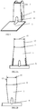
- the invention system comprising a mounting clip and an adjustable shelf systems, contains a back part 1, back wings 2, base plate 3 and in preferred embodiment, a reinforcement 4 in the form of a bulge, which reinforces back part 1 and base plate 3, as shown in FIG 1 .
- the back wings 2 are joined with back part 1 from both side edges, forming an element with substantially U-shaped profile. Between back wings 2 and back part 1 bottom parts are opening slits 5, as shown in FIG 1 , which correspond to shelf rail tube wall thickness on which the mounting clip is mounted.
- the opening slit has a wider width at the bottom than the width at the top.
- the width of the slit at the bottom shall always be larger than the rail tube wall thickness and the width at the top of the slit is same or smaller than the smallest thickness of the wall band to be expected. This is to secure no gap is left due to tolerances of the rail thickness while mounting.
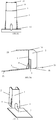
- the back part 1 has trapezoid shape.
- back part 1 has rectangular shape, as shown in FIG 2A, 2B and 2C .
- the back part 1 on FIG 2A has a wider base 6 than top 7 creating a width of the base 6 with wings that is wider than the outer parameter of the opening slots of the rail, while on FIG 2B , the back part has a wider top 8 compared to the base 9 creating a width of the base 9 with wings is narrower than the inner parameter of the opening slots of the rail.
- back part 1 has an equal width resulting in a similar width at base 10 and top 11 with wings bent inwards or outwards creating a width of the base with wings is wider/narrower than the inner parameter of the opening slots of the rail.
- the difference between the top and base dimensions 6-7, 8-9 and 10-11 of the back part 1 creates an angle that determines the angle of the back wings 12, 13 and 14.
- the width of the back part top 15, 16 and 17 is equal in different provided embodiments.
- the back wings 2 typically consist of a bottom bevel 18 and top bevel 19 as shown in FIG 3 . Between the back part 1 and base plate 3 is an obtuse angle, when the mounting clip is not mounted.
- the back wings 2 top front angle 20 and back wings 2 lower parts angles 21 are similar to the angle 22 of the base plate 3 towards the horizontal plane.
- the flexible area between the base plate 3 and the back part 1 is created by the slit 5 in back wings 2.
- the rigidity of the flexible area is mainly determined by the length of the slit 5, the thickness of the material and width of the base 6, 9, 10, but also by existence of a bulge.
- Another flexible area is on the lower part of the back wings 2 that will flex when entering the opening slit in the rail (not shown on drawings).
- the bulge 4 increases the strength for resisting the bending of the base plate 3 upwards, as shown in FIG 4A and 4B . It is understood that the size of the bulge 4 determines the force that the base plate 3 resists. The bulge 4, however, made with excessive influence, provides the possibility to pack and store objects of the adjustable shelf.
- the base plate 3 has rounded edges 23 in front to reduce the risk of interference with objects placed in the shelf.
- the bottom side 24 of the base plate 3 has a high friction material added on all over or in alternative solutions on parts of the surface.
- the high friction material is typically a rubber material or similar that has a friction coefficient.
- the high friction material typically has an adhesive on the backside that is permanently fixated to the bottom side 24 of the base plate 3.
- the friction material may also have a surface structure that increases the friction even more.
- the high friction material together with the force applied through the base plate 3 origin from the clip being snapped in its final position prevents the shelf board from being moved sideways or forward.
- the friction is created through having parts of the base plate 3 bent downwards 25 for creating a sharp edge 26.
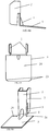
- FIG 6A shows a mounting clip in an unmounted position.
- the angle between the base plate 3 and the back part 1 is larger than 90 degrees.
- FIG 6B shows the mounting clip in its final mounted position having an angle equal to 90 degrees between the base plate 3 and the back part 1.
- the width of the slits (5) at the bottom is larger than the rail (27) wall thickness and the width at the top of the slit (5) is same or smaller than the smallest thickness of the rail (27) wall.
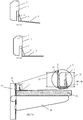
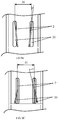
- FIG 7A and 7B The initial state of mounting process of the mounting clip on a shelf system, which consists of a rail 27, bracket 28 and shelf board 29 is shown on FIG 7A and 7B , where FIG 7B is an enlargement of the specified area A of FIG 7A .
- the mounting of the mounting clip is done by positioning the mounting clip in the opening slots 30 of the rails 27.
- the mounting clip will automatically be in backward tilted position when positioned on the shelf board 29 as the angle between base plate 3 and back part 1 is larger than 90 degrees.
- the height 31 of the mounting clip in its backward tilted position is smaller than the distance 32 between the shelf board 29 and the upper perimeter 33 of the opening slot 30 of the rail 27.
- FIG 8A and 8B displays the final positioning of the mounting clip into the opening slot 30 of the rail 27.
- the angle between back part 1 and base plate 3 is equal to 90 degrees.
- the height 33 of the mounting clip in its final mounting is larger than the distance 32 between the shelf board 29 and the upper perimeter 31 of the opening slot 30 in the rail 27.
- FIG 9A shows the described embodiment, as shown on FIG 2A , of the mounting clip in mounted position, where the upper part of the back wings 2 and the opening slots 30 of the rail are in the same centre to centre measurement 35.
- the flexible parts of the back wings are bent inwards during the mounting, when guided by the outer side parameters of the opening slots 30 in rail 27 until the slit 5 (not shown on a figure) in the back wings passes through to opening slots 30 in the rail 27 where the flexible part of the back wings snaps back to its relaxed original position.
- FIG 9B shows the described embodiment, as shown on FIG 2B , which has the upper part of the back wing 2 and the opening slots 30 of the rail 27 in the same centre to centre measurement 36.
- the flexible parts of the back wings are bent outwards during the mounting, when being guided by the outer side parameters of the opening slots 30 in rail 27 until the slit 5 in the back wings as shown in FIG 9 in flexible part of the back wings 2, passes through to opening slots 30 where the flexible part snaps back to it at relaxed original position.
- FIG 9C shows the described embodiment, as shown on FIG 2C , which has the upper part of the back wing 2 and the opening slots 30 of the rail 27 in the same centre to centre measurement 37.
- the flexible part of the back wings are bent outwards or inwards during the mounting, dependent on the original relaxed positioning of the flexible wings, being guided by the inner side parameter or outer side parameters of the opening slots 30 in rail 27 until the slit 5 in the back wings of FIG 9 passes through to opening, where the flexible part snaps back to it in relaxed original position.
- FIG 10 shows a mounted shelf system including the mounting clip with two rails 27 ready for use.
- the shelf board 29 is supported by the brackets 28.
- the number of rails 27 needed can be multiple and is dependent on the length of the shelf board 29.
- FIG 11 shows the mounting clip as it is positioned into the opening slots 30 in the rail 27 and there through positioned and locked for downward and sideway movements.
- the mounting clip is locked towards upward forces, which are applied on the shelf board 29 by the upper part of the clip back wings 2 towards the top of the rail opening slots 30 and forward by the upper bevelled front part of the back wings 2 towards the top of the rail opening slots 30 and locking, with snap, of the back wings 2 towards the rail 27.
- the locking sideways and forward between the mounting clip and the shelf board 29 is done through friction between the base plate 3 and the shelf board 29 surface.
- the mounting clip After the shelf board is placed on the bracket, which is positioned at the right height in the rail, the mounting clip is fixed.
- the adjustable mounting clip is mounted through positioning its' back wings in the slots of the rail and by pushing it inwards in locking position.
- the adjustable mounting clip automatically locks its position between the shelf board and upper part of the rail slot.
- the upper part of the clip, which enters the slot, has an angle to secure fastening and the lower flat part of the clip has an angle to ease the mounting of the clip and for applying a spring force to the shelf board.
- the locking between the clip and the shelf board is obtained, separate or in combination, either through having the edges on the flat part closest to the rail bent in a reversed angle compared to the remaining flat surface creating a sharp edge to the shelf board or through applying a high friction material on the flat surface.
- the locking between the clip and the rail is obtained through positioning of the upper part of the backward facing clips in the upper part of the opening of the rails.
- the backwards facing wings have an angle facing either inwards or outwards leading to a bending of the wings as the clip is placed in position. When the clip reaches its final position, the wings will pass through the opening and create a snap in fixation.
- Removing of the clip is most easily done through placing a sharp instrument like a table knife or a screwdriver on the upper part between the rail and the clip and by tilting the clip gently forward.
Landscapes
- Engineering & Computer Science (AREA)
- General Engineering & Computer Science (AREA)
- Mechanical Engineering (AREA)
- Furniture Connections (AREA)
- Connection Of Plates (AREA)
- Tables And Desks Characterized By Structural Shape (AREA)
Claims (11)
- System umfassend einen Montageclip und ein verstellbares Regalsystem, wobei das Regalsystem eine Regalschiene (27) beinhaltet, die Öffnungsschlitze (30), eine Halterung (28), einen Regalboden (29) hat, der von der Halterung (28) unterstützt wird, wobei der Montageclip im Öffnungsschlitz (30) der Schiene (27) angeordnet ist, wobei der Montageclip zum automatischen verschließen (29) in eine fixierte Position (28) einen Rückenteil (1), einen Hinterflügel (2), die mit dem Rückenteil (1) von beiden Seitenkanten verbunden sind und ein Element mit einem wesentlich U-förmigen Profil bildet, sowie eine Bodenplatte (3) umfasst, wobei der Oberteil der Hinterflügel (2) des Montageclips, das in die Öffnungsschlitze (30) eingreift, einen Winkel zur sicheren Befestigung besitzt und die Bodenplatte (3) des Montageclips einen Winkel zur Vereinfachung der Montage des Clips und zur Anwendung einer Federkraft auf den Regalboden (29) hat und wobei zwischen den Hinterflügeln (2) und dem Rückenteil (1) Spalten (5) die Unterteile des Montageclips bilden, wobei die Breite der Spalten (5) unten größer als die Wandbreite der Schiene (27) ist und die Breite der Oberseite der Spalte (5) dasselbe oder kleiner als die kleinste Breite der Wand der Schiene (27) ist, wobei wenn der Montageclip seine Endposition erreicht, werden die Hinterflügel (2) die Öffnungsschlitze (30) durchlaufen und eine Einrastbefestigung bilden, wobei der ursprüngliche Montageprozess des Montageclips am Regalsystem durch die Positionierung des Montageclips in die Öffnungsschlitze (30) der Schienen (27) erreicht wird, wobei der Montageclip automatisch in einer nach hinten geneigten Position sein wird, wenn er auf den Regalboden (29) angebracht wird, weil der Winkel zwischen der Bodenplatte (3) und dem Rückenteil (1) größer als 90 Grad ist, wobei die Höhe des Montageclips in seiner nach hinten geneigten Position kleiner als der Abstand (32) zwischen dem Regalboden (29) und dem oberen Umfang (33) des Öffnungsschlitzes (30) der Schiene (27) ist, wobei in der Endposition der Winkel zwischen dem Rückenteil (1) und der Bodenplatte (3) 90 Grad beträgt und die Höhe des Montageclips in seiner Endposition größer als der Abstand (32) zwischen dem Regalboden (29) und dem oberen Umfang (31) des Öffnungsschlitzes (30) der Schiene (27) ist.
- System umfassend einen Montageclip und ein verstellbares Regalsystem nach Anspruch 1, gekennzeichnet dadurch, dass der Montageclip eine Bewehrung (4) umfasst, die den Rückenteil (1) und die Bodenplatte (3) verstärkt.
- System umfassend einen Montageclip und ein verstellbares Regalsystem nach Anspruch 1 oder 2, gekennzeichnet dadurch, dass die Bewehrung (4) gewölbt ist.
- System umfassend einen Montageclip und ein verstellbares Regalsystem nach Anspruch 1, gekennzeichnet dadurch, dass die Höhe des Montageclips den Öffnungsschlitzen (30) der rohrförmigen Schiene (27), der Breite des Regalbodens (29) und der Höhe der Halterung (28) entspricht.
- System umfassend einen Montageclip und ein verstellbares Regalsystem nach Anspruch 1, gekennzeichnet dadurch, dass der Rückenteil (1) einen breiteren Unterteil (6) als Oberteil (7) hat und trapezförmig ist oder der Rückenteil (1) einen breiteren Oberteil (11) als Unterteil (10) hat und trapezförmig ist.
- System umfassend einen Montageclip und ein verstellbares Regalsystem nach Anspruch 1, gekennzeichnet dadurch, dass der Rückenteil (1) rechteckig ist.
- System umfassend einen Montageclip und ein verstellbares Regalsystem nach Anspruch 1, gekennzeichnet dadurch, dass es zwischen der Bodenplatte (3) und dem Rückenteil (1) einen flexiblen Bereich gibt.
- System umfassend einen Montageclip und ein verstellbares Regalsystem nach Anspruch 7, gekennzeichnet dadurch, dass die Steifigkeit des flexiblen Bereichs von der Länge der Spalte (5), der Dicke des Materials, der Breite der Bodenplatte (3) und dem Vorhandensein einer Wölbung bestimmt wird.
- System umfassend einen Montageclip und ein verstellbares Regalsystem nach Anspruch 5 und 6, gekennzeichnet dadurch, dass die Breite des Bodens des Rückenteils (1) breiter als der äußere Parameter der Öffnungsschlitze (30) der Schiene (27) oder die Breite des Bodens der Rückenseite (1) enger als der innere Parameter der Öffnungsschlitze der Schiene ist.
- System umfassend einen Montageclip und ein verstellbares Regalsystem nach Anspruch 1, gekennzeichnet dadurch, dass die Bodenplatte (3) Ecken hat, die spitze Winkel oder gerundete Ecken sind.
- System umfassend einen Montageclip und ein verstellbares Regalsystem nach Anspruch 1, gekennzeichnet dadurch, dass auf die Oberfläche der Bodenplatte (3) reibungsbeständiges Material überall oder teilweise angebracht ist.
Applications Claiming Priority (1)
| Application Number | Priority Date | Filing Date | Title |
|---|---|---|---|
| EEP201600002A EE201600002A (et) | 2016-02-11 | 2016-02-11 | Paigaldusklamber kohandatavatele riiulisüsteemidele |
Publications (2)
| Publication Number | Publication Date |
|---|---|
| EP3205894A1 EP3205894A1 (de) | 2017-08-16 |
| EP3205894B1 true EP3205894B1 (de) | 2021-05-19 |
Family
ID=59559905
Family Applications (1)
| Application Number | Title | Priority Date | Filing Date |
|---|---|---|---|
| EP17155499.1A Active EP3205894B1 (de) | 2016-02-11 | 2017-02-09 | System mit einer montageklammer und einem einstellbaren regalsystem |
Country Status (3)
| Country | Link |
|---|---|
| US (1) | US10111522B2 (de) |
| EP (1) | EP3205894B1 (de) |
| EE (1) | EE201600002A (de) |
Families Citing this family (6)
| Publication number | Priority date | Publication date | Assignee | Title |
|---|---|---|---|---|
| USD848827S1 (en) * | 2017-03-20 | 2019-05-21 | K-International, Inc. | Under shelf bracket with wedge |
| WO2020102743A1 (en) | 2018-11-16 | 2020-05-22 | Parallax Group International, Llc | Wall and ceiling track systems for mounting devices |
| US20210020075A1 (en) * | 2019-07-18 | 2021-01-21 | K-International, Inc. | Secure grip sign holder |
| KR102372532B1 (ko) * | 2020-03-11 | 2022-03-08 | 곽병두 | 인조대리석 욕실선반 |
| US11224289B1 (en) * | 2020-08-21 | 2022-01-18 | Del Hutson Designs, Llc | Shelf support assembly |
| US12239224B2 (en) * | 2021-04-06 | 2025-03-04 | DriFlower, LLC | Vegetation hanging and drying system and brackets thereof |
Family Cites Families (26)
| Publication number | Priority date | Publication date | Assignee | Title |
|---|---|---|---|---|
| US836045A (en) | 1905-10-19 | 1906-11-13 | Edward Melchior | Adjustable shelf-supporting bracket. |
| US977609A (en) * | 1910-05-16 | 1910-12-06 | Grand Rapids Show Case Co | Adjustable detachable bracket. |
| GB414180A (en) | 1933-04-04 | 1934-08-02 | Brooks J B & Co Ltd | Improvements relating to means for adjustably supporting shelves |
| GB618669A (en) | 1946-11-11 | 1949-02-24 | Augustine Francis Marlowe | Improvements in or relating to brackets or supports for shelves and other fittings |
| US3041033A (en) * | 1960-10-03 | 1962-06-26 | Farwell Ozum Kirk And Company | Multipurpose supporting bracket |
| FR1400530A (fr) * | 1964-04-15 | 1965-05-28 | Cotexunion | Etagère perfectionnée |
| US3471112A (en) * | 1967-11-21 | 1969-10-07 | Px Ind Inc | Combination shelf support and anchor |
| NL7607876A (en) | 1976-07-15 | 1978-01-17 | Grosse Maurice | Adjustable support system for shelves - has uprights with reentrant grooves receiving shelf bracket clips having locking surfaces |
| US4151917A (en) | 1977-06-09 | 1979-05-01 | TAP Plastics, Inc. | Shelf system |
| US4406374A (en) * | 1981-08-12 | 1983-09-27 | Myco, Inc. | Locking device for display rack |
| IE57060B1 (en) | 1985-11-12 | 1992-04-08 | Allport Brian | Shelf support bracket |
| GB2194134B (en) | 1986-08-15 | 1990-07-11 | Natwell Holdings Limited | Shelving |
| US4934642A (en) | 1989-03-29 | 1990-06-19 | Australian Slatwall Industries Pty Ltd. | Shelf-support bracket |
| US6109461A (en) * | 1996-07-01 | 2000-08-29 | John Sterling Corporation | Shelf mounting system including mounting brackets having mounting ears for mounting vertical track members to a wall |
| DE29710445U1 (de) * | 1997-06-16 | 1997-08-21 | J. Langenbach GmbH, 63450 Hanau | Wandaufhängungsteil, insbesondere zum Präsentieren, Halten und Lagern von Gegenständen |
| GB2347844B (en) | 1999-03-19 | 2003-01-15 | Elodie Ann Waite | Shelving system |
| US6364263B1 (en) | 2000-06-06 | 2002-04-02 | James A. Ryan | Fixture support system |
| US7744052B2 (en) * | 2005-01-14 | 2010-06-29 | Wooten Metal, Inc. | Shelf bracket and method of making same |
| EP1829463A1 (de) | 2006-03-03 | 2007-09-05 | Element -System Rudolf Bohnacker GmbH | Regalbodenträger mit Distanzelementen |
| DE202007002694U1 (de) * | 2007-02-23 | 2007-08-23 | Ehl, Joseph | Wandregal mit Wangen |
| US20120119043A1 (en) * | 2010-11-16 | 2012-05-17 | Fasteners For Retail, Inc. | Locking mechanism for trays |
| US9775437B2 (en) * | 2012-05-18 | 2017-10-03 | James M Stark, III | Anchor system for extruded columns |
| US9945403B2 (en) * | 2013-03-04 | 2018-04-17 | Paul Fabis | Rigid foam board installation clip |
| USD786053S1 (en) * | 2014-03-03 | 2017-05-09 | Paul Fabis | Clip |
| US9277814B2 (en) | 2014-05-21 | 2016-03-08 | Aaron James Winker | Adjustable continuous shelf mounting systems and apparatuses related thereto |
| US20180132611A1 (en) * | 2016-11-17 | 2018-05-17 | Sumter Easy Home LLC | Ventilated shelving bracket for horizontal and vertical hang rail system |
-
2016
- 2016-02-11 EE EEP201600002A patent/EE201600002A/et unknown
-
2017
- 2017-02-09 EP EP17155499.1A patent/EP3205894B1/de active Active
- 2017-02-10 US US15/429,266 patent/US10111522B2/en active Active
Non-Patent Citations (1)
| Title |
|---|
| None * |
Also Published As
| Publication number | Publication date |
|---|---|
| EP3205894A1 (de) | 2017-08-16 |
| US10111522B2 (en) | 2018-10-30 |
| US20170231384A1 (en) | 2017-08-17 |
| EE201600002A (et) | 2017-09-15 |
Similar Documents
| Publication | Publication Date | Title |
|---|---|---|
| EP3205894B1 (de) | System mit einer montageklammer und einem einstellbaren regalsystem | |
| US7987799B2 (en) | Adjustable shelf | |
| US4205815A (en) | Shelf bracket, shelf bracket-stud combination and shelf bracket-clip combination | |
| US20230276940A1 (en) | Wall-Mounted, Configurable Storage System | |
| US4671481A (en) | Antidislodgement clips | |
| US5624168A (en) | Cabinet mounting apparatus | |
| US20100288554A1 (en) | Universal adjustable support bracket for electrical junction boxes | |
| US12049758B1 (en) | Apparatus and method for hanging architectural panels with concealed attachment points | |
| US20200069082A1 (en) | Organizer set with retention system and method of making same | |
| US10058173B2 (en) | Shelving assembly and method of assembly | |
| EP2586334A1 (de) | Haltevorrichtung | |
| US20030233965A1 (en) | Shelving system | |
| EP3226667B1 (de) | Mehrteiliger regalfachboden | |
| US4730738A (en) | Adjustably tiltable wall shelf assembly | |
| US7104411B2 (en) | System for detachable suspension of shelves, drawers or the like | |
| EP3422903B1 (de) | Wandaufhängersystem | |
| EP2886012B1 (de) | Befestigungssytem für möbel | |
| US10905238B1 (en) | Bracket for drawer slide rail | |
| US10149540B2 (en) | Snap-in bracket for slidable racks and method of use | |
| RU2672701C2 (ru) | Потолочная подвесная система | |
| EP3483355B1 (de) | Wandpaneel mit integriertem befestigungsclip | |
| US10070723B1 (en) | Attachment bracket | |
| US20180347603A1 (en) | Toolless Mounting System For An Electronics Rack Component | |
| WO2000007483A1 (en) | Shelf bracket | |
| US20260026617A1 (en) | Cabinet system |
Legal Events
| Date | Code | Title | Description |
|---|---|---|---|
| PUAI | Public reference made under article 153(3) epc to a published international application that has entered the european phase |
Free format text: ORIGINAL CODE: 0009012 |
|
| STAA | Information on the status of an ep patent application or granted ep patent |
Free format text: STATUS: THE APPLICATION HAS BEEN PUBLISHED |
|
| AK | Designated contracting states |
Kind code of ref document: A1 Designated state(s): AL AT BE BG CH CY CZ DE DK EE ES FI FR GB GR HR HU IE IS IT LI LT LU LV MC MK MT NL NO PL PT RO RS SE SI SK SM TR |
|
| AX | Request for extension of the european patent |
Extension state: BA ME |
|
| STAA | Information on the status of an ep patent application or granted ep patent |
Free format text: STATUS: REQUEST FOR EXAMINATION WAS MADE |
|
| 17P | Request for examination filed |
Effective date: 20180215 |
|
| RBV | Designated contracting states (corrected) |
Designated state(s): AL AT BE BG CH CY CZ DE DK EE ES FI FR GB GR HR HU IE IS IT LI LT LU LV MC MK MT NL NO PL PT RO RS SE SI SK SM TR |
|
| STAA | Information on the status of an ep patent application or granted ep patent |
Free format text: STATUS: EXAMINATION IS IN PROGRESS |
|
| 17Q | First examination report despatched |
Effective date: 20180508 |
|
| GRAP | Despatch of communication of intention to grant a patent |
Free format text: ORIGINAL CODE: EPIDOSNIGR1 |
|
| STAA | Information on the status of an ep patent application or granted ep patent |
Free format text: STATUS: GRANT OF PATENT IS INTENDED |
|
| INTG | Intention to grant announced |
Effective date: 20201208 |
|
| GRAS | Grant fee paid |
Free format text: ORIGINAL CODE: EPIDOSNIGR3 |
|
| GRAA | (expected) grant |
Free format text: ORIGINAL CODE: 0009210 |
|
| STAA | Information on the status of an ep patent application or granted ep patent |
Free format text: STATUS: THE PATENT HAS BEEN GRANTED |
|
| AK | Designated contracting states |
Kind code of ref document: B1 Designated state(s): AL AT BE BG CH CY CZ DE DK EE ES FI FR GB GR HR HU IE IS IT LI LT LU LV MC MK MT NL NO PL PT RO RS SE SI SK SM TR |
|
| REG | Reference to a national code |
Ref country code: GB Ref legal event code: FG4D |
|
| REG | Reference to a national code |
Ref country code: CH Ref legal event code: EP |
|
| REG | Reference to a national code |
Ref country code: DE Ref legal event code: R096 Ref document number: 602017038703 Country of ref document: DE |
|
| REG | Reference to a national code |
Ref country code: AT Ref legal event code: REF Ref document number: 1394252 Country of ref document: AT Kind code of ref document: T Effective date: 20210615 |
|
| REG | Reference to a national code |
Ref country code: IE Ref legal event code: FG4D |
|
| REG | Reference to a national code |
Ref country code: LT Ref legal event code: MG9D |
|
| REG | Reference to a national code |
Ref country code: AT Ref legal event code: MK05 Ref document number: 1394252 Country of ref document: AT Kind code of ref document: T Effective date: 20210519 |
|
| REG | Reference to a national code |
Ref country code: NL Ref legal event code: MP Effective date: 20210519 |
|
| PG25 | Lapsed in a contracting state [announced via postgrant information from national office to epo] |
Ref country code: HR Free format text: LAPSE BECAUSE OF FAILURE TO SUBMIT A TRANSLATION OF THE DESCRIPTION OR TO PAY THE FEE WITHIN THE PRESCRIBED TIME-LIMIT Effective date: 20210519 Ref country code: BG Free format text: LAPSE BECAUSE OF FAILURE TO SUBMIT A TRANSLATION OF THE DESCRIPTION OR TO PAY THE FEE WITHIN THE PRESCRIBED TIME-LIMIT Effective date: 20210819 Ref country code: AT Free format text: LAPSE BECAUSE OF FAILURE TO SUBMIT A TRANSLATION OF THE DESCRIPTION OR TO PAY THE FEE WITHIN THE PRESCRIBED TIME-LIMIT Effective date: 20210519 Ref country code: FI Free format text: LAPSE BECAUSE OF FAILURE TO SUBMIT A TRANSLATION OF THE DESCRIPTION OR TO PAY THE FEE WITHIN THE PRESCRIBED TIME-LIMIT Effective date: 20210519 Ref country code: LT Free format text: LAPSE BECAUSE OF FAILURE TO SUBMIT A TRANSLATION OF THE DESCRIPTION OR TO PAY THE FEE WITHIN THE PRESCRIBED TIME-LIMIT Effective date: 20210519 |
|
| PG25 | Lapsed in a contracting state [announced via postgrant information from national office to epo] |
Ref country code: LV Free format text: LAPSE BECAUSE OF FAILURE TO SUBMIT A TRANSLATION OF THE DESCRIPTION OR TO PAY THE FEE WITHIN THE PRESCRIBED TIME-LIMIT Effective date: 20210519 Ref country code: GR Free format text: LAPSE BECAUSE OF FAILURE TO SUBMIT A TRANSLATION OF THE DESCRIPTION OR TO PAY THE FEE WITHIN THE PRESCRIBED TIME-LIMIT Effective date: 20210820 Ref country code: IS Free format text: LAPSE BECAUSE OF FAILURE TO SUBMIT A TRANSLATION OF THE DESCRIPTION OR TO PAY THE FEE WITHIN THE PRESCRIBED TIME-LIMIT Effective date: 20210919 Ref country code: PT Free format text: LAPSE BECAUSE OF FAILURE TO SUBMIT A TRANSLATION OF THE DESCRIPTION OR TO PAY THE FEE WITHIN THE PRESCRIBED TIME-LIMIT Effective date: 20210920 Ref country code: NO Free format text: LAPSE BECAUSE OF FAILURE TO SUBMIT A TRANSLATION OF THE DESCRIPTION OR TO PAY THE FEE WITHIN THE PRESCRIBED TIME-LIMIT Effective date: 20210819 Ref country code: PL Free format text: LAPSE BECAUSE OF FAILURE TO SUBMIT A TRANSLATION OF THE DESCRIPTION OR TO PAY THE FEE WITHIN THE PRESCRIBED TIME-LIMIT Effective date: 20210519 Ref country code: SE Free format text: LAPSE BECAUSE OF FAILURE TO SUBMIT A TRANSLATION OF THE DESCRIPTION OR TO PAY THE FEE WITHIN THE PRESCRIBED TIME-LIMIT Effective date: 20210519 Ref country code: RS Free format text: LAPSE BECAUSE OF FAILURE TO SUBMIT A TRANSLATION OF THE DESCRIPTION OR TO PAY THE FEE WITHIN THE PRESCRIBED TIME-LIMIT Effective date: 20210519 |
|
| PG25 | Lapsed in a contracting state [announced via postgrant information from national office to epo] |
Ref country code: NL Free format text: LAPSE BECAUSE OF FAILURE TO SUBMIT A TRANSLATION OF THE DESCRIPTION OR TO PAY THE FEE WITHIN THE PRESCRIBED TIME-LIMIT Effective date: 20210519 |
|
| PG25 | Lapsed in a contracting state [announced via postgrant information from national office to epo] |
Ref country code: SM Free format text: LAPSE BECAUSE OF FAILURE TO SUBMIT A TRANSLATION OF THE DESCRIPTION OR TO PAY THE FEE WITHIN THE PRESCRIBED TIME-LIMIT Effective date: 20210519 Ref country code: SK Free format text: LAPSE BECAUSE OF FAILURE TO SUBMIT A TRANSLATION OF THE DESCRIPTION OR TO PAY THE FEE WITHIN THE PRESCRIBED TIME-LIMIT Effective date: 20210519 Ref country code: CZ Free format text: LAPSE BECAUSE OF FAILURE TO SUBMIT A TRANSLATION OF THE DESCRIPTION OR TO PAY THE FEE WITHIN THE PRESCRIBED TIME-LIMIT Effective date: 20210519 Ref country code: EE Free format text: LAPSE BECAUSE OF FAILURE TO SUBMIT A TRANSLATION OF THE DESCRIPTION OR TO PAY THE FEE WITHIN THE PRESCRIBED TIME-LIMIT Effective date: 20210519 Ref country code: DK Free format text: LAPSE BECAUSE OF FAILURE TO SUBMIT A TRANSLATION OF THE DESCRIPTION OR TO PAY THE FEE WITHIN THE PRESCRIBED TIME-LIMIT Effective date: 20210519 Ref country code: RO Free format text: LAPSE BECAUSE OF FAILURE TO SUBMIT A TRANSLATION OF THE DESCRIPTION OR TO PAY THE FEE WITHIN THE PRESCRIBED TIME-LIMIT Effective date: 20210519 Ref country code: ES Free format text: LAPSE BECAUSE OF FAILURE TO SUBMIT A TRANSLATION OF THE DESCRIPTION OR TO PAY THE FEE WITHIN THE PRESCRIBED TIME-LIMIT Effective date: 20210519 |
|
| REG | Reference to a national code |
Ref country code: DE Ref legal event code: R097 Ref document number: 602017038703 Country of ref document: DE |
|
| PLBE | No opposition filed within time limit |
Free format text: ORIGINAL CODE: 0009261 |
|
| STAA | Information on the status of an ep patent application or granted ep patent |
Free format text: STATUS: NO OPPOSITION FILED WITHIN TIME LIMIT |
|
| 26N | No opposition filed |
Effective date: 20220222 |
|
| PGFP | Annual fee paid to national office [announced via postgrant information from national office to epo] |
Ref country code: GB Payment date: 20220222 Year of fee payment: 6 |
|
| PG25 | Lapsed in a contracting state [announced via postgrant information from national office to epo] |
Ref country code: IS Free format text: LAPSE BECAUSE OF FAILURE TO SUBMIT A TRANSLATION OF THE DESCRIPTION OR TO PAY THE FEE WITHIN THE PRESCRIBED TIME-LIMIT Effective date: 20210919 Ref country code: AL Free format text: LAPSE BECAUSE OF FAILURE TO SUBMIT A TRANSLATION OF THE DESCRIPTION OR TO PAY THE FEE WITHIN THE PRESCRIBED TIME-LIMIT Effective date: 20210519 |
|
| PGFP | Annual fee paid to national office [announced via postgrant information from national office to epo] |
Ref country code: FR Payment date: 20220224 Year of fee payment: 6 |
|
| PG25 | Lapsed in a contracting state [announced via postgrant information from national office to epo] |
Ref country code: IT Free format text: LAPSE BECAUSE OF FAILURE TO SUBMIT A TRANSLATION OF THE DESCRIPTION OR TO PAY THE FEE WITHIN THE PRESCRIBED TIME-LIMIT Effective date: 20210519 |
|
| PG25 | Lapsed in a contracting state [announced via postgrant information from national office to epo] |
Ref country code: MC Free format text: LAPSE BECAUSE OF FAILURE TO SUBMIT A TRANSLATION OF THE DESCRIPTION OR TO PAY THE FEE WITHIN THE PRESCRIBED TIME-LIMIT Effective date: 20210519 |
|
| REG | Reference to a national code |
Ref country code: CH Ref legal event code: PL |
|
| REG | Reference to a national code |
Ref country code: BE Ref legal event code: MM Effective date: 20220228 |
|
| PG25 | Lapsed in a contracting state [announced via postgrant information from national office to epo] |
Ref country code: LU Free format text: LAPSE BECAUSE OF NON-PAYMENT OF DUE FEES Effective date: 20220209 |
|
| PG25 | Lapsed in a contracting state [announced via postgrant information from national office to epo] |
Ref country code: LI Free format text: LAPSE BECAUSE OF NON-PAYMENT OF DUE FEES Effective date: 20220228 Ref country code: IE Free format text: LAPSE BECAUSE OF NON-PAYMENT OF DUE FEES Effective date: 20220209 Ref country code: CH Free format text: LAPSE BECAUSE OF NON-PAYMENT OF DUE FEES Effective date: 20220228 |
|
| PG25 | Lapsed in a contracting state [announced via postgrant information from national office to epo] |
Ref country code: BE Free format text: LAPSE BECAUSE OF NON-PAYMENT OF DUE FEES Effective date: 20220228 |
|
| PGFP | Annual fee paid to national office [announced via postgrant information from national office to epo] |
Ref country code: DE Payment date: 20230227 Year of fee payment: 7 |
|
| GBPC | Gb: european patent ceased through non-payment of renewal fee |
Effective date: 20230209 |
|
| PG25 | Lapsed in a contracting state [announced via postgrant information from national office to epo] |
Ref country code: GB Free format text: LAPSE BECAUSE OF NON-PAYMENT OF DUE FEES Effective date: 20230209 |
|
| PG25 | Lapsed in a contracting state [announced via postgrant information from national office to epo] |
Ref country code: GB Free format text: LAPSE BECAUSE OF NON-PAYMENT OF DUE FEES Effective date: 20230209 Ref country code: FR Free format text: LAPSE BECAUSE OF NON-PAYMENT OF DUE FEES Effective date: 20230228 |
|
| PG25 | Lapsed in a contracting state [announced via postgrant information from national office to epo] |
Ref country code: HU Free format text: LAPSE BECAUSE OF FAILURE TO SUBMIT A TRANSLATION OF THE DESCRIPTION OR TO PAY THE FEE WITHIN THE PRESCRIBED TIME-LIMIT; INVALID AB INITIO Effective date: 20170209 |
|
| PG25 | Lapsed in a contracting state [announced via postgrant information from national office to epo] |
Ref country code: MK Free format text: LAPSE BECAUSE OF FAILURE TO SUBMIT A TRANSLATION OF THE DESCRIPTION OR TO PAY THE FEE WITHIN THE PRESCRIBED TIME-LIMIT Effective date: 20210519 Ref country code: CY Free format text: LAPSE BECAUSE OF FAILURE TO SUBMIT A TRANSLATION OF THE DESCRIPTION OR TO PAY THE FEE WITHIN THE PRESCRIBED TIME-LIMIT Effective date: 20210519 |
|
| REG | Reference to a national code |
Ref country code: DE Ref legal event code: R119 Ref document number: 602017038703 Country of ref document: DE |
|
| PG25 | Lapsed in a contracting state [announced via postgrant information from national office to epo] |
Ref country code: MT Free format text: LAPSE BECAUSE OF FAILURE TO SUBMIT A TRANSLATION OF THE DESCRIPTION OR TO PAY THE FEE WITHIN THE PRESCRIBED TIME-LIMIT Effective date: 20210519 |
|
| PG25 | Lapsed in a contracting state [announced via postgrant information from national office to epo] |
Ref country code: DE Free format text: LAPSE BECAUSE OF NON-PAYMENT OF DUE FEES Effective date: 20240903 |
|
| PG25 | Lapsed in a contracting state [announced via postgrant information from national office to epo] |
Ref country code: DE Free format text: LAPSE BECAUSE OF NON-PAYMENT OF DUE FEES Effective date: 20240903 |
|
| PG25 | Lapsed in a contracting state [announced via postgrant information from national office to epo] |
Ref country code: TR Free format text: LAPSE BECAUSE OF FAILURE TO SUBMIT A TRANSLATION OF THE DESCRIPTION OR TO PAY THE FEE WITHIN THE PRESCRIBED TIME-LIMIT Effective date: 20210519 |