EP3205840B1 - Rotorlagerungssystem für eine gasturbine mit formgedächtnislegierungskomponente - Google Patents
Rotorlagerungssystem für eine gasturbine mit formgedächtnislegierungskomponente Download PDFInfo
- Publication number
- EP3205840B1 EP3205840B1 EP17155175.7A EP17155175A EP3205840B1 EP 3205840 B1 EP3205840 B1 EP 3205840B1 EP 17155175 A EP17155175 A EP 17155175A EP 3205840 B1 EP3205840 B1 EP 3205840B1
- Authority
- EP
- European Patent Office
- Prior art keywords
- load
- recoupling
- bearing
- support frame
- support system
- Prior art date
- Legal status (The legal status is an assumption and is not a legal conclusion. Google has not performed a legal analysis and makes no representation as to the accuracy of the status listed.)
- Active
Links
Images


Classifications
-
- F—MECHANICAL ENGINEERING; LIGHTING; HEATING; WEAPONS; BLASTING
- F02—COMBUSTION ENGINES; HOT-GAS OR COMBUSTION-PRODUCT ENGINE PLANTS
- F02C—GAS-TURBINE PLANTS; AIR INTAKES FOR JET-PROPULSION PLANTS; CONTROLLING FUEL SUPPLY IN AIR-BREATHING JET-PROPULSION PLANTS
- F02C7/00—Features, components parts, details or accessories, not provided for in, or of interest apart form groups F02C1/00 - F02C6/00; Air intakes for jet-propulsion plants
- F02C7/20—Mounting or supporting of plant; Accommodating heat expansion or creep
-
- F—MECHANICAL ENGINEERING; LIGHTING; HEATING; WEAPONS; BLASTING
- F01—MACHINES OR ENGINES IN GENERAL; ENGINE PLANTS IN GENERAL; STEAM ENGINES
- F01D—NON-POSITIVE DISPLACEMENT MACHINES OR ENGINES, e.g. STEAM TURBINES
- F01D25/00—Component parts, details, or accessories, not provided for in, or of interest apart from, other groups
- F01D25/16—Arrangement of bearings; Supporting or mounting bearings in casings
- F01D25/162—Bearing supports
- F01D25/164—Flexible supports; Vibration damping means associated with the bearing
-
- F—MECHANICAL ENGINEERING; LIGHTING; HEATING; WEAPONS; BLASTING
- F01—MACHINES OR ENGINES IN GENERAL; ENGINE PLANTS IN GENERAL; STEAM ENGINES
- F01D—NON-POSITIVE DISPLACEMENT MACHINES OR ENGINES, e.g. STEAM TURBINES
- F01D21/00—Shutting-down of machines or engines, e.g. in emergency; Regulating, controlling, or safety means not otherwise provided for
- F01D21/04—Shutting-down of machines or engines, e.g. in emergency; Regulating, controlling, or safety means not otherwise provided for responsive to undesired position of rotor relative to stator or to breaking-off of a part of the rotor, e.g. indicating such position
- F01D21/045—Shutting-down of machines or engines, e.g. in emergency; Regulating, controlling, or safety means not otherwise provided for responsive to undesired position of rotor relative to stator or to breaking-off of a part of the rotor, e.g. indicating such position special arrangements in stators or in rotors dealing with breaking-off of part of rotor
-
- F—MECHANICAL ENGINEERING; LIGHTING; HEATING; WEAPONS; BLASTING
- F01—MACHINES OR ENGINES IN GENERAL; ENGINE PLANTS IN GENERAL; STEAM ENGINES
- F01D—NON-POSITIVE DISPLACEMENT MACHINES OR ENGINES, e.g. STEAM TURBINES
- F01D21/00—Shutting-down of machines or engines, e.g. in emergency; Regulating, controlling, or safety means not otherwise provided for
- F01D21/04—Shutting-down of machines or engines, e.g. in emergency; Regulating, controlling, or safety means not otherwise provided for responsive to undesired position of rotor relative to stator or to breaking-off of a part of the rotor, e.g. indicating such position
- F01D21/08—Restoring position
-
- F—MECHANICAL ENGINEERING; LIGHTING; HEATING; WEAPONS; BLASTING
- F01—MACHINES OR ENGINES IN GENERAL; ENGINE PLANTS IN GENERAL; STEAM ENGINES
- F01D—NON-POSITIVE DISPLACEMENT MACHINES OR ENGINES, e.g. STEAM TURBINES
- F01D25/00—Component parts, details, or accessories, not provided for in, or of interest apart from, other groups
- F01D25/16—Arrangement of bearings; Supporting or mounting bearings in casings
- F01D25/162—Bearing supports
-
- F—MECHANICAL ENGINEERING; LIGHTING; HEATING; WEAPONS; BLASTING
- F02—COMBUSTION ENGINES; HOT-GAS OR COMBUSTION-PRODUCT ENGINE PLANTS
- F02C—GAS-TURBINE PLANTS; AIR INTAKES FOR JET-PROPULSION PLANTS; CONTROLLING FUEL SUPPLY IN AIR-BREATHING JET-PROPULSION PLANTS
- F02C7/00—Features, components parts, details or accessories, not provided for in, or of interest apart form groups F02C1/00 - F02C6/00; Air intakes for jet-propulsion plants
- F02C7/06—Arrangements of bearings; Lubricating
-
- F—MECHANICAL ENGINEERING; LIGHTING; HEATING; WEAPONS; BLASTING
- F16—ENGINEERING ELEMENTS AND UNITS; GENERAL MEASURES FOR PRODUCING AND MAINTAINING EFFECTIVE FUNCTIONING OF MACHINES OR INSTALLATIONS; THERMAL INSULATION IN GENERAL
- F16C—SHAFTS; FLEXIBLE SHAFTS; ELEMENTS OR CRANKSHAFT MECHANISMS; ROTARY BODIES OTHER THAN GEARING ELEMENTS; BEARINGS
- F16C27/00—Elastic or yielding bearings or bearing supports, for exclusively rotary movement
- F16C27/04—Ball or roller bearings, e.g. with resilient rolling bodies
-
- F—MECHANICAL ENGINEERING; LIGHTING; HEATING; WEAPONS; BLASTING
- F05—INDEXING SCHEMES RELATING TO ENGINES OR PUMPS IN VARIOUS SUBCLASSES OF CLASSES F01-F04
- F05D—INDEXING SCHEME FOR ASPECTS RELATING TO NON-POSITIVE-DISPLACEMENT MACHINES OR ENGINES, GAS-TURBINES OR JET-PROPULSION PLANTS
- F05D2220/00—Application
- F05D2220/30—Application in turbines
- F05D2220/32—Application in turbines in gas turbines
-
- F—MECHANICAL ENGINEERING; LIGHTING; HEATING; WEAPONS; BLASTING
- F05—INDEXING SCHEMES RELATING TO ENGINES OR PUMPS IN VARIOUS SUBCLASSES OF CLASSES F01-F04
- F05D—INDEXING SCHEME FOR ASPECTS RELATING TO NON-POSITIVE-DISPLACEMENT MACHINES OR ENGINES, GAS-TURBINES OR JET-PROPULSION PLANTS
- F05D2240/00—Components
- F05D2240/20—Rotors
- F05D2240/24—Rotors for turbines
- F05D2240/242—Rotors for turbines of reaction type
-
- F—MECHANICAL ENGINEERING; LIGHTING; HEATING; WEAPONS; BLASTING
- F05—INDEXING SCHEMES RELATING TO ENGINES OR PUMPS IN VARIOUS SUBCLASSES OF CLASSES F01-F04
- F05D—INDEXING SCHEME FOR ASPECTS RELATING TO NON-POSITIVE-DISPLACEMENT MACHINES OR ENGINES, GAS-TURBINES OR JET-PROPULSION PLANTS
- F05D2240/00—Components
- F05D2240/50—Bearings
- F05D2240/54—Radial bearings
-
- F—MECHANICAL ENGINEERING; LIGHTING; HEATING; WEAPONS; BLASTING
- F05—INDEXING SCHEMES RELATING TO ENGINES OR PUMPS IN VARIOUS SUBCLASSES OF CLASSES F01-F04
- F05D—INDEXING SCHEME FOR ASPECTS RELATING TO NON-POSITIVE-DISPLACEMENT MACHINES OR ENGINES, GAS-TURBINES OR JET-PROPULSION PLANTS
- F05D2240/00—Components
- F05D2240/60—Shafts
-
- F—MECHANICAL ENGINEERING; LIGHTING; HEATING; WEAPONS; BLASTING
- F05—INDEXING SCHEMES RELATING TO ENGINES OR PUMPS IN VARIOUS SUBCLASSES OF CLASSES F01-F04
- F05D—INDEXING SCHEME FOR ASPECTS RELATING TO NON-POSITIVE-DISPLACEMENT MACHINES OR ENGINES, GAS-TURBINES OR JET-PROPULSION PLANTS
- F05D2240/00—Components
- F05D2240/90—Mounting on supporting structures or systems
- F05D2240/91—Mounting on supporting structures or systems on a stationary structure
-
- F—MECHANICAL ENGINEERING; LIGHTING; HEATING; WEAPONS; BLASTING
- F05—INDEXING SCHEMES RELATING TO ENGINES OR PUMPS IN VARIOUS SUBCLASSES OF CLASSES F01-F04
- F05D—INDEXING SCHEME FOR ASPECTS RELATING TO NON-POSITIVE-DISPLACEMENT MACHINES OR ENGINES, GAS-TURBINES OR JET-PROPULSION PLANTS
- F05D2260/00—Function
- F05D2260/15—Load balancing
-
- F—MECHANICAL ENGINEERING; LIGHTING; HEATING; WEAPONS; BLASTING
- F05—INDEXING SCHEMES RELATING TO ENGINES OR PUMPS IN VARIOUS SUBCLASSES OF CLASSES F01-F04
- F05D—INDEXING SCHEME FOR ASPECTS RELATING TO NON-POSITIVE-DISPLACEMENT MACHINES OR ENGINES, GAS-TURBINES OR JET-PROPULSION PLANTS
- F05D2300/00—Materials; Properties thereof
- F05D2300/10—Metals, alloys or intermetallic compounds
- F05D2300/17—Alloys
- F05D2300/172—Copper alloys
- F05D2300/1723—Nickel-Copper alloy, e.g. Monel
-
- F—MECHANICAL ENGINEERING; LIGHTING; HEATING; WEAPONS; BLASTING
- F05—INDEXING SCHEMES RELATING TO ENGINES OR PUMPS IN VARIOUS SUBCLASSES OF CLASSES F01-F04
- F05D—INDEXING SCHEME FOR ASPECTS RELATING TO NON-POSITIVE-DISPLACEMENT MACHINES OR ENGINES, GAS-TURBINES OR JET-PROPULSION PLANTS
- F05D2300/00—Materials; Properties thereof
- F05D2300/10—Metals, alloys or intermetallic compounds
- F05D2300/17—Alloys
- F05D2300/173—Aluminium alloys, e.g. AlCuMgPb
-
- F—MECHANICAL ENGINEERING; LIGHTING; HEATING; WEAPONS; BLASTING
- F05—INDEXING SCHEMES RELATING TO ENGINES OR PUMPS IN VARIOUS SUBCLASSES OF CLASSES F01-F04
- F05D—INDEXING SCHEME FOR ASPECTS RELATING TO NON-POSITIVE-DISPLACEMENT MACHINES OR ENGINES, GAS-TURBINES OR JET-PROPULSION PLANTS
- F05D2300/00—Materials; Properties thereof
- F05D2300/10—Metals, alloys or intermetallic compounds
- F05D2300/17—Alloys
- F05D2300/174—Titanium alloys, e.g. TiAl
-
- F—MECHANICAL ENGINEERING; LIGHTING; HEATING; WEAPONS; BLASTING
- F05—INDEXING SCHEMES RELATING TO ENGINES OR PUMPS IN VARIOUS SUBCLASSES OF CLASSES F01-F04
- F05D—INDEXING SCHEME FOR ASPECTS RELATING TO NON-POSITIVE-DISPLACEMENT MACHINES OR ENGINES, GAS-TURBINES OR JET-PROPULSION PLANTS
- F05D2300/00—Materials; Properties thereof
- F05D2300/50—Intrinsic material properties or characteristics
- F05D2300/505—Shape memory behaviour
-
- Y—GENERAL TAGGING OF NEW TECHNOLOGICAL DEVELOPMENTS; GENERAL TAGGING OF CROSS-SECTIONAL TECHNOLOGIES SPANNING OVER SEVERAL SECTIONS OF THE IPC; TECHNICAL SUBJECTS COVERED BY FORMER USPC CROSS-REFERENCE ART COLLECTIONS [XRACs] AND DIGESTS
- Y02—TECHNOLOGIES OR APPLICATIONS FOR MITIGATION OR ADAPTATION AGAINST CLIMATE CHANGE
- Y02T—CLIMATE CHANGE MITIGATION TECHNOLOGIES RELATED TO TRANSPORTATION
- Y02T50/00—Aeronautics or air transport
- Y02T50/60—Efficient propulsion technologies, e.g. for aircraft
Definitions
- the present subject matter relates generally to gas turbine engines and, more particularly, to a rotor support system for a gas turbine engine having one or more shape memory alloy components.
- Gas turbine engines typically include a rotor assembly, a compressor, and a turbine.
- the rotor assembly includes a fan that has an array of fan blades extending radially outward from a rotor shaft.
- the rotor shaft transfers power and rotary motion from the turbine to both the compressor and the fan and is supported longitudinally using a plurality of bearing assemblies. Additionally, the rotor assembly has an axis of rotation that passes through a rotor center of gravity.
- Known bearing assemblies include rolling elements and a paired race, wherein the rolling elements are supported within the paired race.
- the rotor assembly is typically supported on three bearing assemblies, one of which is a thrust bearing assembly and two of which are roller bearing assemblies.
- the thrust bearing assembly supports the rotor shaft and minimizes axial and radial movement of the rotor shaft assembly.
- the remaining roller bearing assemblies support radial movement of the rotor shaft.
- a fragment of one of the fan blades may become separated from the remainder of the blade. Accordingly, a substantial unbalanced rotary load may be created within the damaged fan and must be carried substantially by the fan shaft bearings, the fan bearing supports, and the fan support frames.
- known gas turbine engines include support components for the fan rotor support system that are sized to provide additional strength.
- increasing the strength of the support components undesirably increases an overall weight of the engine and decreases an overall efficiency of the engine when the engine is operated without substantial rotor imbalances.
- LRD load reduction device
- an improved rotor support system that is configured to accommodate unbalanced or increased loading conditions without resulting in a permanent decoupling of the fan rotor from the rotor support system would be welcomed in the technology.
- a rotor support system comprises a fan trust bearing in a front position and a roller bearing in an aft position.
- the fan thrust bearing is supported by blades made from a shape memory material.
- GB 2 444 935 discloses a single roller bearing which is supported by radially extending annular panels.
- the bearing is coupled to the thus provided structure by means of a frangible bolt designed to fail if a threshold load is exceeded. After failure of the frangible bolt the bearing is supported by radially extending spokes which may comprise a shape memory metal, such as an Ni-Ti or Ti-Nb alloy.
- US 6,109,022 discloses a rotor support system in which an arrangement of two axially spaced bearings are both supported by a frangible member and an essentially meander-shaped resilient support member.
- a rotor support system for a gas turbine engine is provided according to claim 1.
- first and second outer bearing housings may be formed from a super-elastic shape memory alloy that allows the first and second outer bearing housings to undergo recoverable deformation without failing when the fuse portion fails.
- the present subject matter is directed to a rotor support system for supporting a rotor shaft of a gas turbine engine relative to a corresponding support frame of the engine.
- the system may include a bearing assembly and a load reduction member coupled between the bearing assembly and the support frame of the engine.
- the load reduction member may include a fuse portion configured to fail when an excessive load is transmitted through the member.
- the system may include a load recoupling member that is configured to maintain a mechanical connection between the bearing assembly and the support frame when the fuse portion of the load reduction member fails.
- the load recoupling member may be formed from a super-elastic shape memory alloy that allows the load recoupling member to provide a high support stiffness under low or reduced loading conditions and low support stiffness under high or increased loading conditions.
- the properties of the shape memory alloy may allow the load recoupling member to plastically deform or otherwise undergo recoverable deformation under high loads (e.g., loads sufficient to result in failure of the fuse portion of the load reduction member) without failing, thereby allowing the load recoupling member to absorb/dampen the increased loads while maintaining a mechanical connection between the bearing assembly and the support frame.
- the properties of the shape memory alloy may allow the load recoupling member to regain its original shape and, thus, provide a desired amount of support stiffness between the bearing assembly and the support frame.
- FIG. 1 illustrates a cross-sectional view of one embodiment of a gas turbine engine 10 that may be utilized within an aircraft in accordance with aspects of the present subject matter, with the engine 10 being shown having a longitudinal or axial centerline axis 12 extending therethrough for reference purposes.
- the engine 10 may include a core gas turbine engine (indicated generally by reference character 14) and a fan section 16 positioned upstream thereof.
- the core engine 14 may generally include a substantially tubular outer casing 18 that defines an annular inlet 20.
- the outer casing 18 may further enclose and support a booster compressor 22 for increasing the pressure of the air that enters the core engine 14 to a first pressure level.
- a high pressure, multi-stage, axial-flow compressor 24 may then receive the pressurized air from the booster compressor 22 and further increase the pressure of such air.
- the pressurized air exiting the high-pressure compressor 24 may then flow to a combustor 26 within which fuel is injected into the flow of pressurized air, with the resulting mixture being combusted within the combustor 26.
- the high energy combustion products are directed from the combustor 26 along the hot gas path of the engine 10 to a first (high pressure) turbine 28 for driving the high pressure compressor 24 via a first (high pressure) drive shaft 30, and then to a second (low pressure) turbine 32 for driving the booster compressor 22 and fan section 16 via a second (low pressure) drive shaft 34 that is generally coaxial with first drive shaft 30.
- the combustion products may be expelled from the core engine 14 via an exhaust nozzle 36 to provide propulsive jet thrust.
- the fan section 16 of the engine 10 may generally include a rotatable, axial-flow fan rotor assembly 38 that is configured to be surrounded by an annular fan casing 40.
- the fan casing 40 may be configured to be supported relative to the core engine 14 by a plurality of substantially radially-extending, circumferentially-spaced outlet guide vanes 42.
- a bearing support frame 108 FIG. 2
- the fan casing 40 may enclose the fan rotor assembly 38 and its corresponding fan rotor blades 44.
- a downstream section 46 of the fan casing 40 may extend over an outer portion of the core engine 14 so as to define a secondary, or by-pass, airflow conduit 48 that provides additional propulsive jet thrust.
- the second (low pressure) drive shaft 34 may be directly coupled to the fan rotor assembly 38 to provide a direct-drive configuration.
- the second drive shaft 34 may be coupled to the fan rotor assembly 38 via a speed reduction device 37 (e.g., a reduction gear or gearbox) to provide an indirect-drive or geared drive configuration.
- a speed reduction device(s) may also be provided between any other suitable shafts and/or spools within the engine as desired or required.
- an initial air flow may enter the engine 10 through an associated inlet 52 of the fan casing 40.
- the air flow 50 then passes through the fan blades 44 and splits into a first compressed air flow (indicated by arrow 54) that moves through conduit 48 and a second compressed air flow (indicated by arrow 56) which enters the booster compressor 22.
- the pressure of the second compressed air flow 56 is then increased and enters the high pressure compressor 24 (as indicated by arrow 58).
- the combustion products 60 exit the combustor 26 and flow through the first turbine 28. Thereafter, the combustion products 60 flow through the second turbine 32 and exit the exhaust nozzle 36 to provide thrust for the engine 10.
- the rotor assembly 38 may generally include a rotor shaft 102 (e.g., shaft 34 shown in FIG. 1 ) configured to support an array of fan blades 44 ( FIG. 1 ) of the rotor assembly 38 extending radially outwardly from a corresponding rotor disc (not shown).
- a rotor shaft 102 e.g., shaft 34 shown in FIG. 1
- the rotor assembly 38 may generally include a rotor shaft 102 (e.g., shaft 34 shown in FIG. 1 ) configured to support an array of fan blades 44 ( FIG. 1 ) of the rotor assembly 38 extending radially outwardly from a corresponding rotor disc (not shown).
- the rotor shaft 102 may be supported within the engine 10 through one or more axially spaced bearing assemblies 104, 106 of the rotor support system 100, with each bearing assembly 104, 106 being configured to rotationally support the rotor shaft 102 relative to a structural support frame 108 of the gas turbine engine 10.
- a first bearing assembly 104 may be coupled between the rotor shaft 102 and the support frame 108 via a load reduction member 110 of the rotor support system 100.
- a second bearing assembly 106 may be coupled between the rotor shaft 102 and the support frame 108 at a location axially aft of the first bearing assembly 104.
- the first bearing assembly 104 may be located at the number one bearing position within the engine 10 and may correspond to a roller bearing assembly whereas the second bearing assembly 106 may be located at the number two bearing position within the engine 10 and may correspond to a fan thrust bearing.
- the first and second bearing assemblies 104, 106 may generally be positioned within an annular, sealed compartment 112 of the engine 10 defined between the rotor shaft 102 and the support frame 108.
- the first bearing assembly 104 may generally include a bearing 114 and an outer bearing housing 116 extending radially outwardly from the bearing 114.
- the bearing 114 may include an inner race 118, an outer race 120 positioned radially outwardly from the inner race 118 and a plurality of rolling elements 122 (only one of which is shown) disposed between the inner and outer races 118, 120.
- the rolling elements 122 may generally correspond to any suitable bearing elements, such as balls or rollers.
- the outer race 120 of the bearing 114 is formed integrally with the outer bearing housing 116.
- the outer race 120 may correspond to a separate component from the outer bearing housing 116 (e.g., as shown in FIG. 5 ).
- the outer race 120 of the bearing 114 may be configured to interface with and/or be coupled to the radially inner end of the outer bearing housing 116.
- the outer bearing housing 116 may be configured to be coupled to the load reduction member 110 of the disclosed system 100 such that the load reduction member 110 extends lengthwise between the first bearing assembly 104 and the support frame 108.
- the load reduction member 110 may extend lengthwise between a first end 124 and a second end 126, with the first end 124 being coupled to the outer bearing housing 116 and the second end 126 being coupled to the support frame 108.
- the outer bearing housing 116 of the first bearing assembly 104 and the load reduction member 110 are shown as separate components configured to be separately coupled to one another (e.g., via a bolt 128 or other suitable fastener).
- the outer bearing housing 116 and the load reduction member 110 may be formed integrally with one another.
- the load reduction member 110 may be configured to function as a load reduction device (LRD) for the disclosed system 100.
- the load reduction member 110 may include a fuse portion 130 positioned between its first and second ends 124, 126 that is configured to fail upon application of an excessive load through the member 110.
- the fuse portion 130 is spaced apart from the ends 124, 126 of the load reduction member 100 such that the member includes a forward segment 132 extending lengthwise between the first end 124 and the fuse portion 130 and an aft segment 134 extending lengthwise between the fuse portion 130 and the second end 126.
- the fuse portion 130 may fail between the forward and aft segments 132, 134.
- an unbalance within the engine 10 may cause significantly high radial forces to be applied through the fan section 16 of the engine 10 and into the bearing assemblies 104, 106 supporting the rotor assembly 38. If the radial force exceeds a given load threshold, the fuse portion 130 of the load reduction member 110 may fail, thereby severing the direct coupling provided between the forward and aft segments 132, 134 of the load reduction member 110.
- the disclosed system 100 may include a load recoupling means for maintaining the connection between the first bearing assembly 104 and the support frame 108 when the fuse portion 130 of the load reduction member 110 fails.
- the system 100 may include a load recoupling member 136 provided between the first bearing assembly 104 and the support frame 108 to prevent the decoupling of such components upon failure of the load reduction member 110.
- the load recoupling member 136 may be coupled to the load reduction member 110 along opposite sides of the fuse portion 130.
- the load recouping member 136 may extend lengthwise between a forward end 138 and an aft end 140, with the forward end 138 being coupled to the forward segment 132 of the load reduction member 110 and the aft end 140 being coupled to the aft segment 134 of the load reduction member 110.
- the load recoupling member 136 may provide a connection between the forward and aft segments 132, 134 of the load reduction member 110, thereby maintaining a mechanical connection between the first bearing assembly 104 and the support frame 108.
- the load recoupling member 136 may, in several embodiments, be formed from a super-elastic shape memory alloy to allow the load recoupling member 136 to plastically deform during high loading events and then regain its original shape during normal loading events.
- the shape memory alloy may allow for the load recoupling member 136 to undergo a large recoverable deformation without failing when the loads being transmitted between the support frame 108 and the rotor shaft 102 exceed the predetermined load threshold at which the fuse portion 130 of the load reduction member 110 is configured to fail (e.g., during a fan blade out (FBO) event).
- FBO fan blade out
- Such deformation may allow for a reduced support stiffness to be provided between the support frame 108 and the first bearing assembly 104 during the high loading event, thereby allowing the increased loads to be absorbed or dampened by the system 100 without requiring the support frame 108 to be completely decoupled from the first bearing assembly 104.
- the shape memory alloy forming the load recoupling member 136 may be configured to exhibit high stiffness, thereby allowing the load recoupling member 136 to provide increased support stiffness between the support frame 108 and the first bearing assembly 104.
- the load recoupling member 136 may recover all the strain and return to its original high stiffness regime to provide increased support stiffness during windmill.
- the load recoupling member 136 may be formed from any suitable shape-memory alloy that allows the load recoupling member 136 to function as described herein.
- the load recoupling member 136 may be formed from a super-elastic, metal-based shape memory alloy.
- a suitable super-elastic, metal-based shape memory alloy may include, but is not limited to, a nickel-titanium (NiTi) alloy, a NiTi-based alloy (e.g., a nickel-titanium-hafnium (NiTiHf) alloy, a nickel-titanium-vanadium (NiTiVd) alloy, a nickel-titanium-palladium (NiTiPd) alloy, a nickel-titanium-copper (NiTiCu), a nickel-titanium-niobium (NiTiNb) alloy), a nickel-aluminum-copper (Ni-Al-Cu) alloy and other non-nickel based alloys, such as titanium-niobium (Ti-Nb) alloys, copper-zinc-aluminum (CuZnAl) alloys, and copper-aluminum- beryllium (CuAlBe) alloys.
- the shape memory alloy utilized in accordance with aspects of the present subject matter may be selected such that the load recoupling member 136 undergoes recoverable deformation when the loads transmitted through the member 136 exceed a first load threshold and subsequently recovers back to its initial shape once the load drops below a second, lower load threshold.
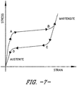
- FIG. 7 provides an example stress-strain curve illustrating the material properties of a suitable super-elastic shape memory alloy. As shown, at a first load threshold (defined by points A and B in FIG. 7 ), the shape memory alloy may undergo a large strain (e.g., for NiTi, typically in the range of 2% to 4%), thereby allowing the shape-memory alloy to deform and provide reduced stiffness.
- point A in FIG. 7 represents the start of the solid-solid phase transformation from austenite to martensite
- point B in FIG. 7 represents the end of this solid-solid phase transformation.
- the shape memory alloy may recover all the strain once the load drops below a second load threshold (defined by points C and D in FIG. 7 ), thereby allowing the shape memory alloy to return back to its initial shape and provide increased stiffness.
- point C in FIG. 7 represents the start of the reverse phase transformation from marteniste to austenite
- point D represents the end of this reverse phase transformation.
- the material properties of the shape memory alloy used herein may be selected such that the first load threshold (defined by points A and B in FIG. 7 ) is less than, equal to or greater than the predetermined load threshold at which the fuse portion 130 is configured to fail, depending on the desired performance of the system 100.
- the load recoupling member 136 may also define or include suitable features to enhance the elasticity and/or deformability of the load recoupling member 136 during high loading events and/or to increase the support stiffness of the load recoupling member 136 during normal or reduced loading conditions.
- the load recoupling member 136 may define an area 142 of reduced thickness between its forward and aft ends 132, 134.
- the load recoupling member 136 may also define a cage-like configuration that includes circumferentially spaced ribs 144 extending between its forward and aft ends 132, 134.
- the load recoupling member 136 may generally be configured to be coupled to the load reduction member 110 using any suitable attachments means and/or methodology.
- the forward segment 132 of the load reduction member 110 may include a forward mounting flange 146 extending radially outwardly relative to the remainder of the forward segment 132 and the aft segment 134 of the load reduction member 110 may include an aft mounting flange 148 extending radially outwardly relative to the remainder of the aft segment 134.
- the forward and aft ends 138, 140 of the load recoupling member 136 may be configured to be coupled to the forward and aft mounting flanges 146, 148, respectively, of the load reduction member 110.
- the ends 138, 140 of the load recoupling member 136 may be coupled to the respective mounting flanges 146, 148 using one or more suitable mechanical fasteners, via welding and/or using any other suitable attachments means and/or methodology.
- the fuse portion 130 of the load reduction member 110 may generally have any suitable configuration that allows the fuse portion 130 to fail when the load transmitted through the load reduction member 110 exceeds the predetermined load threshold.
- the fuse portion 130 is formed by an area of reduced thickness defined between the forward and aft segments 132, 134 of the load reduction member 110.
- the fuse portion 130 may have any other suitable configuration, such as by forming a fusible link between the forward and aft segments 132, 134 using an intermediate structure or a suitable joint (e.g., a bolted joint between the forward and aft segments 132, 134 including bolts or other fasteners configured shear off or otherwise fail at the predetermined load threshold).
- the second bearing assembly 106 of the disclosed rotor support system 100 may include a bearing 150, an outer bearing housing 152 extending radially between the bearing 150 and the support frame 108 and an inner bearing support 154 extending radially between the bearing 150 and the rotor shaft 102.
- the bearing 150 may generally include an inner race 156, an outer race 158 positioned radially outwardly from the inner race 156 and a plurality of rolling elements 160 (only one of which is shown) disposed between the inner and outer races 156, 158.
- the rolling elements 160 may generally correspond to any suitable bearing elements, such as balls or rollers.
- the outer bearing housing 152 may generally extend radially between an inner housing end 162 and an outer housing end 164, with the inner housing end 162 being positioned adjacent to the bearing 150 and the outer housing end 164 positioned adjacent to the support frame 108.
- the inner housing end 162 may generally be configured to interface with and/or be coupled to the outer race 158 of the bearing 150.
- the outer housing end 164 may define a mounting flange or other suitable feature for coupling the outer housing end 164 to the support frame 108 (e.g., via bolts 166 or other suitable fasteners). For instance, as shown in FIG.
- common bolts 166 may be used to couple both the outer housing end 164 of the outer bearing housing 152 and the second end 126 of the load reduction member 110 to the support frame 108.
- the outer bearing housing 152 and the load reduction member 110 may be coupled to the support frame 108 at separate locations and/or using separate fasteners.
- the inner bearing support 154 may generally extend radially between an outer support end 170 and an inner support end 172, with the outer support end 170 being positioned adjacent to the bearing 150 and the inner support end 172 positioned adjacent to the rotor frame.
- the outer support end 170 may generally be configured to interface with and/or be coupled to the inner race 156 of the bearing 150.
- the inner support end 172 of the inner bearing support 154 may be configured to be rotatably coupled to the rotor shaft 102 (e.g., via a mounting race 174 coupled between the inner bearing support 154 and the rotor shaft 102).
- each outer bearing housing 116, 152 of the bearing assemblies 104, 106 may also be formed from a super-elastic shape memory alloy.
- each outer bearing housing 116, 152 may be formed from a suitable super-elastic shape memory alloy to allow the outer bearing housing 116, 152 to undergo a large recoverable deformation during high loading events but maintain sufficient support stiffness for its respective bearing assembly 104, 106 during normal or reduced loading conditions.
- the shape memory alloy of the outer bearing housings 116, 152 may deform to provide additional load damping within the system 100.
- one or both of the outer bearing housings 116, 152 may also define or include suitable features to enhance the elasticity and/or deformability of the housing(s) 116, 152 during high loading events.
- the outer bearing housing 152 of the second bearing assembly 106 may define an area 168 of reduced thickness between its inner and outer housing ends 162, 164.
- FIGS. 3 and 4 one embodiment of both a structural configuration and a mounting configuration for the load recoupling member 136 described above is illustrated in accordance with aspects of the present subject matter.
- FIG. 3 illustrates a perspective view of the load reduction member 110 shown in FIG. 2 with the load recoupling member 136 being installed thereon.
- FIG. 4 illustrates a close-up view of a portion of the load reduction member 110 and the load recoupling member 136 shown in FIG. 3 .
- the load recouping member 136 may have a split-cage configuration. Specifically, as shown in FIG. 3 , the load recoupling member 136 may be formed from a plurality of circumferential cage segments 136A spaced apart from another around the outer perimeter of the load reduction member 110.
- each circumferential segment 136A may be formed from a super-elastic shape memory alloy and may generally extend lengthwise between a forward end 138 and an aft end 140, with the forward end 138 being configured to be coupled to the forward mounting flange 146 of the load reduction member 110 and the aft end 140 being configured to be coupled to the aft mounting flange 148 of the load reduction member 110. It should be appreciated that the specific circumferential spacing provided between each pair of adjacent circumferential cage segments 136A may generally depend on the number of segments 136A installed on the load reduction member 110 as well as the circumferential length of each segment 136A.
- the circumferential cage segments 136A may be configured to be spaced apart equally around the outer perimeter of the load reduction member 110. It should also be appreciated that the specific number of segments 136A and/or the geometry of the segments 136A may be selected to allow the load recoupling member 136 to provide the desired support stiffness between the first bearing assembly 104 and the support frame 106.
- each circumferential cage segment 136A may include a plurality of circumferentially spaced ribs 144 extending lengthwise between its forward and aft ends 138, 140.
- each cage segment 136A includes four ribs 144 spaced apart along the circumferential length of the segment 136A.
- each cage segment 136A may include any other suitable number of ribs 144, such as by including less than four ribs or greater than four ribs.
- each rib 144 may be configured to define at least a portion of the area 142 of reduced thickness of the load recoupling member 136 (e.g., as described above with reference to FIG. 2 ).
- the load recoupling member 136 may have any other suitable configuration.
- the load recoupling member 136 may have a ring-cage configuration forming a complete 360 degree ring around the outer perimeter of the load reduction member 110, such as by coupling two or more circumferential cage segments around the load reduction member 110 such that the cage segments circumferentially abut to form an annular cage structure around the entire outer perimeter of the load reduction member 110.
- FIG. 5 a cross-sectional view of another embodiment of a rotor support system 200 suitable for use within a gas turbine engine 10 is illustrated in accordance with aspects of the present subject matter, particularly illustrating the rotor support system 200 installed relative to the fan rotor assembly 38 of the gas turbine engine 10.
- the rotor support system 200 may be configured the same as or similar to the system 100 described above with reference to FIG. 2 .
- the system 200 may include a first bearing assembly 204 and a second bearing assembly 206, with the first bearing assembly 204 being coupled between the rotor shaft 102 and the support frame 108 via a load reduction member 210 and the second bearing assembly 206 being coupled between the rotor shaft 102 and the support frame 108 at a location axially aft of the first bearing assembly 204.
- the first bearing assembly 204 may include a bearing 214 and an outer bearing housing 216 extending radially outwardly from the bearing 214, with the bearing 214 including an inner race 218, an outer race 220 positioned radially outwardly from the inner race 218 and a plurality of rolling elements 222 (only one of which is shown) disposed between the inner and outer races 218, 220.
- the outer race 220 of the bearing 214 corresponds to a separate component configured to interface with and/or be coupled to the outer bearing housing 216 of the first bearing assembly 204.
- the second bearing assembly 206 may generally include a bearing 250, an outer bearing housing 252 extending radially between the bearing 250 and the support frame 108 and an inner bearing support 254 extending radially between the bearing 250 and the rotor shaft 102.
- the bearing 250 may generally include an inner race 256, an outer race 258 positioned radially outwardly from the inner race 256 and a plurality of rolling elements 260 (only one of which is shown) disposed between the inner and outer races 256, 258.
- the load reduction member 210 may generally extend lengthwise between a first end 224 and a second end 226, with the first end 224 being coupled to the outer bearing housing 216 of the first bearing assembly 204 and the second end 226 being coupled to the support frame 208. Similar to the system 100 described above, the load reduction member 210 may generally be configured to function as a load reduction device (LRD) for the disclosed system 200. Specifically, the load reduction member 210 may include a fuse portion 230 positioned between its first and second ends 224, 226 that is configured to fail upon application of an excessive load through the member 210. For example, as shown in FIG.
- the fuse portion 230 is spaced apart from the ends 224, 226 of the load reduction member 210 such that the member 210 includes a forward segment 232 extending lengthwise between the first end 224 and the fuse portion 230 and an aft segment 234 extending lengthwise between the fuse portion 230 and the second end 226. As such, when an excessive load is applied through the load reduction member 210, the fuse portion 230 may fail between the forward and aft segments 232, 234.
- the system 200 may also include a load recoupling member 236 provided between first bearing assembly 204 and the support frame 108 so as to maintain a mechanical connection between the first bearing assembly 204 and the support frame 108 when the fuse portion 230 of the load reduction member 210 fails.
- a load recoupling member 236 provided between first bearing assembly 204 and the support frame 108 so as to maintain a mechanical connection between the first bearing assembly 204 and the support frame 108 when the fuse portion 230 of the load reduction member 210 fails.
- the load recoupling member 236 may be configured to be coupled directly between the first bearing assembly 204 and the support frame 108.
- the load recouping member 236 may extend lengthwise between a forward end 238 and an aft end 240, with the forward end 238 being coupled directly to the outer bearing housing 216 of the first bearing assembly 204 and the aft end 240 being coupled directly to the support frame 108.
- the load recoupling member 236 may maintain a mechanical connection between the first bearing assembly 204 and the support frame 108.
- the members 210, 236 may define similar axial lengths.
- an axial length 280 of the load recoupling member 236 may be substantially equal to an axial length 282 of the load reduction member 210.
- the axial lengths 280, 282 of the members 236, 210 are substantially equal to one another when the axial length 280 of the load recoupling member 236 is equal to the axial length 282 of the load reduction member 210 plus or minus less than 20%, such as plus or minus less than 15% or plus or minus less than 10% or plus or minus less than 5%.
- the load recoupling member 236 may be formed from a super-elastic shape memory alloy, such as a super-elastic, metal-based shape memory alloy. As such, the load recoupling member 236 may plastically deform during high loading events and then regain its original shape during normal or reduced loading events.
- the shape memory alloy may allow for the load recoupling member 236 to undergo a large recoverable deformation without failing when the loads being transmitted between the support frame 108 and the rotor shaft 102 exceed the predetermined load threshold at which the fuse portion 230 of the load reduction member 210 is configured to fail (e.g., during a fan blade out (FBO) event), thereby providing for reduced support stiffness between the support frame 108 and the first bearing assembly 204 during the high loading event.
- FBO fan blade out
- the load recoupling member 236 may be configured to provide high support stiffness.
- the load recoupling member 236 may have a ring-cage configuration forming a complete 360 degree ring designed to extend lengthwise between the first bearing assembly 204 and the support frame 108.
- two or more circumferential cage segments may installed between the first bearing assembly 204 and the support frame 108 such that the segment(s) abut one another in the circumferential direction, thereby forming the annular cage structure.
- the load recoupling member 236 may include a plurality of circumferentially spaced ribs 244 extending lengthwise between its forward and aft ends 238, 240. As shown in FIG. 6 , the ribs 244 are generally spaced apart equally around the circumference of the load recoupling member 236. However, in other embodiments, the circumferential spacing of the ribs 244 may vary around the load recoupling member 236.
- the load recoupling member 236 may have any other suitable configuration.
- the load recoupling member 236 may have a split-cage configuration formed by two or more circumferentially spaced cage segments extending lengthwise between the first bearing assembly 204 and the support frame 108.
Landscapes
- Engineering & Computer Science (AREA)
- General Engineering & Computer Science (AREA)
- Mechanical Engineering (AREA)
- Chemical & Material Sciences (AREA)
- Combustion & Propulsion (AREA)
- Support Of The Bearing (AREA)
- Rolling Contact Bearings (AREA)
- Turbine Rotor Nozzle Sealing (AREA)
Claims (13)
- Rotorhalterungssystem (100, 200) für ein Gasturbinentriebwerk (10), wobei das Rotorhalterungssystem Folgendes umfasst
einen Halterungsrahmen (108),
einen ersten Lagersatz (104, 204), der ein Wälzlager umfasst und
einen zweiten Lagersatz (106, 206), der ein Gebläseaxiallager (150, 250) umfasst,
wobei die Lagersätze axial voneinander versetzt sind und jeder der Lagersätze ein äußeres Lagergehäuse (116, 152; 216, 252) umfasst,
wobei das Rotorhalterungssystem ferner ein Lastverminderungselement (110, 210) umfasst, das axial aus dem Halterungsrahmen auskragt,
wobei das äußere Lagergehäuse (152, 252) des zweiten Lagersatzes (106, 206) direkt an dem Halterungsrahmen angebracht ist und das äußere Lagergehäuse (116, 216) des ersten Lagersatzes (104, 204) über das Lastverminderungselement (110, 210) zwischen dem äußeren Lagergehäuse (116, 216) des ersten Lagersatzes (104, 204) und dem Halterungsrahmen (108) mit dem Halterungsrahmen (108) gekoppelt ist, wobei das Lastverminderungselement (110, 210) einen Sicherungsabschnitt (130, 230) einschließt, der konfiguriert ist, auszufallen, wenn eine durch das Lastverminderungselement (110, 210) übertragene Last einen vorgegebenen Lastschwellenwert überschreitet;
wobei ein Lastwiederankopplungselement (136, 236) zwischen dem ersten Lagersatz (104, 204) und dem Halterungsrahmen (108) bereitgestellt ist und den Sicherungsabschnitt (130, 230) des Lastverminderungselements (110, 210) überbrückt, wobei das Lastwiederankopplungselement (136) aus einer superelastischen Formgedächtnislegierung ausgebildet ist, die es ermöglicht, das Lastwiederankopplungselement (136, 236) einer behebbaren Verformung auszusetzen, ohne auszufallen, wenn der Sicherungsabschnitt (130, 230) ausfällt, sodass das Lastwiederankopplungselement (136, 236) eine mechanische Verbindung zwischen dem ersten Lagersatz (104, 204) und dem Halterungsrahmen (108) aufrechterhält. - Rotorhalterungssystem (100, 200) nach Anspruch 1, wobei das Lastwiederankopplungselement (136, 236) vor dem Ausgesetztwerden der behebbaren Verformung eine Anfangsform aufweist, wobei das Lastwiederankopplungselement (136, 236) konfiguriert ist, der behebbaren Verformung ausgesetzt zu werden, wenn die durch das Lastwiederankopplungselement (136, 236) übertragene Last einen ersten Lastschwellenwert überschreitet und zurück in die Anfangsform behoben wird, sobald die Last unter einen zweiten Lastschwellenfährt fällt, wobei der erste Lastschwellenwert höher ist als der zweite Lastschwellenwert.
- Rotorhalterungssystem (100, 200) nach Anspruch 1 oder 2, wobei das Lastverminderungselement (110, 210) ein vorderes Segment (132, 232), das sich der Länge nach zwischen dem ersten Lagersatz (104, 204) und dem Sicherungsabschnitt (130, 230) erstreckt, und ein hinteres Segment (134, 234), das sich der Länge nach zwischen dem Sicherungsabschnitt (130, 230) und dem Halterungsrahmen (108) erstreckt, einschließt.
- Rotorhalterungssystem (100) nach Anspruch 3, wobei das Lastwiederankopplungselement (136) sich der Länge nach zwischen einem vorderen Ende (138) und einem hinteren Ende (140) erstreckt, wobei das vordere Ende (138) mit dem vorderen Segment (132) des Lastverminderungselements (110) gekoppelt ist und das hintere Ende (140) mit dem hinteren Segment des Lastverminderungselements (110) gekoppelt ist, wobei, wenn der Sicherungsabschnitt (130) ausfällt, das Lastwiederankopplungselement (136) zwischen dem vorderen Segment und dem hinteren Segment des Lastverminderungssegments gekoppelt bleibt, um die mechanische Verbindung zwischen dem Lagersatz und dem Halterungsrahmen aufrechtzuerhalten.
- Rotorhalterungssystem (100) nach Anspruch 4, wobei das Lastverminderungselement (110) einen vorderen Befestigungsflansch (146), der sich von dem vorderen Segment (132) aus erstreckt, und einen hinteren Befestigungsflansch (148), der sich von dem hinteren Segment (134) aus erstreckt, einschließt, wobei das vordere Ende (138) des Lastwiederankopplungselements (136) mit dem vorderen Befestigungsflansch gekoppelt ist und das hintere Ende (140) des Lastwiederankopplungselements mit dem hinteren Befestigungsflansch gekoppelt ist.
- Rotorhalterungssystem (100) nach einem der Ansprüche 3 bis 5, wobei das Lastwiederankopplungselement (136) aus mehreren umlaufenden Segmenten ausgebildet ist, die zwischen dem vorderen und dem hinteren Segment des Lastverminderungselements gekoppelt sind, wobei die mehreren umlaufenden Segmente umlaufend voneinander um den Umfang des Lastverminderungselements herum beabstandet sind.
- Rotorhalterungssystem (100) nach einem der vorhergehenden Ansprüche, wobei das Lastwiederankopplungselement (136) sich der Länge nach zwischen einem vorderen Ende und einem hinteren Ende erstreckt, wobei das Lastwiederankopplungselement mehrere umlaufend beabstandete Rippen (144) einschließt, die sich zwischen dem vorderen Ende und dem hinteren Ende erstrecken.
- Rotorhalterungssystem (200) nach einem der vorhergehenden Ansprüche, wobei das Lastwiederankopplungselement (236) sich der Länge nach zwischen einem vorderen Ende, dass angrenzend an den ersten Lagersatz (204) positioniert ist, und einem hinteren Ende, das angrenzend an den Halterungsrahmen (108) positioniert ist, derart erstreckt, dass das Lastwiederankopplungselement eine axiale Länge (280) definiert, die im Wesentlichen gleich einer axialen Länge des Lastverminderungselements (210) ist.
- Rotorhalterungssystem (200) nach Anspruch 8, wobei das vordere Ende direkt mit dem äußeren Lagergehäuse (216) des ersten Gehäuselagers (204) gekoppelt ist und das hintere Ende direkt mit dem Halterungsrahmen (108) gekoppelt ist.
- Rotorhalterungssystem (100, 200) nach einem der vorhergehenden Ansprüche, wobei der erste Lagersatz (104, 204) ein erstes Lager (114, 214) und ein erstes äußeres Lagergehäuse (116, 216) einschließt, das sich radial nach außen aus dem ersten Lager erstreckt.
- Rotorhalterungssystem (100, 200) nach einem der vorhergehenden Ansprüche, wobei der zweite Lagersatz ein zweites Lager und ein zweites äußeres Lagergehäuse einschließt, das sich radial nach außen aus dem zweiten Lager erstreckt.
- Rotorhalterungssystem (100, 200) nach einem der vorhergehenden Ansprüche, wobei das erste äußere Lagergehäuse (116, 216) und/oder das zweite äußere Lagergehäuse (152, 252) aus einer superelastischen Formgedächtnislegierung ausgebildet ist.
- Gasturbinentriebwerk (10), Folgendes umfassend:eine Rotorwelle (34); undein Rotorhalterungssystem (100, 200) nach einem der vorhergehenden Ansprüche, um die Rotorwelle (34) relativ zu dem Halterungsrahmen (108) zu halten, wobei der Halterungsrahmen (108) radial von der Rotorwelle (34) beabstandet ist.
Applications Claiming Priority (1)
| Application Number | Priority Date | Filing Date | Title |
|---|---|---|---|
| US15/041,136 US10196934B2 (en) | 2016-02-11 | 2016-02-11 | Rotor support system with shape memory alloy components for a gas turbine engine |
Publications (2)
| Publication Number | Publication Date |
|---|---|
| EP3205840A1 EP3205840A1 (de) | 2017-08-16 |
| EP3205840B1 true EP3205840B1 (de) | 2019-12-25 |
Family
ID=57995110
Family Applications (1)
| Application Number | Title | Priority Date | Filing Date |
|---|---|---|---|
| EP17155175.7A Active EP3205840B1 (de) | 2016-02-11 | 2017-02-08 | Rotorlagerungssystem für eine gasturbine mit formgedächtnislegierungskomponente |
Country Status (5)
| Country | Link |
|---|---|
| US (1) | US10196934B2 (de) |
| EP (1) | EP3205840B1 (de) |
| JP (1) | JP2017141827A (de) |
| CN (1) | CN107061017B (de) |
| CA (1) | CA2956915A1 (de) |
Families Citing this family (34)
| Publication number | Priority date | Publication date | Assignee | Title |
|---|---|---|---|---|
| CA3000360C (en) * | 2017-04-14 | 2020-05-26 | General Electric Company | Support assembly having variable stiffness member |
| FR3066534B1 (fr) * | 2017-05-22 | 2020-01-10 | Safran Aircraft Engines | Ensemble pour turbomachine d'aeronef presentant un systeme de decouplage ameliore en cas de perte d'aube de soufflante |
| US10634007B2 (en) | 2017-11-13 | 2020-04-28 | General Electric Company | Rotor support system having a shape memory alloy |
| US10968775B2 (en) | 2017-11-28 | 2021-04-06 | General Electric Company | Support system having shape memory alloys |
| US11261753B2 (en) * | 2017-12-06 | 2022-03-01 | General Electric Company | Method and device for connecting fan rotor to low pressure turbine rotor |
| DE102017223112A1 (de) * | 2017-12-18 | 2019-06-19 | MTU Aero Engines AG | Gehäuseanordnung für eine Strömungsmaschine sowie Strömungsmaschinenanordnung mit einer solchen Gehäuseanordnung und Verfahren zum Herstellen der Gehäuseanordnung |
| CN110005479B (zh) * | 2018-01-05 | 2021-06-29 | 中国航发商用航空发动机有限责任公司 | 航空发动机及其低压转子轴承支撑用熔断降载结构 |
| FR3079550B1 (fr) * | 2018-03-27 | 2020-10-23 | Safran Aircraft Engines | Arbre de turbine d'une turbomachine et procede de protection contre une survitesse dudit arbre |
| FR3081523B1 (fr) | 2018-05-28 | 2021-01-08 | Safran Aircraft Engines | Turbomachine d'aeronef comportant des moyens de decouplage |
| DE102018116019A1 (de) * | 2018-07-02 | 2020-01-02 | Rolls-Royce Deutschland Ltd & Co Kg | Lagervorrichtung zur Lastreduzierung |
| DE102018116018A1 (de) | 2018-07-02 | 2020-01-02 | Rolls-Royce Deutschland Ltd & Co Kg | Lagervorrichtung zur Lastreduzierung |
| FR3093146B1 (fr) | 2019-02-21 | 2021-01-29 | Safran Aircraft Engines | Arbre de transmission comprenant une section fusible et procédé de protection contre un sur-couple d’un tel arbre de transmission |
| US11460037B2 (en) | 2019-03-29 | 2022-10-04 | Pratt & Whitney Canada Corp. | Bearing housing |
| US10808573B1 (en) | 2019-03-29 | 2020-10-20 | Pratt & Whitney Canada Corp. | Bearing housing with flexible joint |
| US10844746B2 (en) * | 2019-03-29 | 2020-11-24 | Pratt & Whitney Canada Corp. | Bearing housing |
| CN111894737B (zh) * | 2019-05-05 | 2021-07-30 | 中国航发商用航空发动机有限责任公司 | 转子支承结构以及燃气轮机 |
| CN111980958B (zh) * | 2019-05-21 | 2021-09-10 | 中国航发商用航空发动机有限责任公司 | 一种熔断系统和航空发动机 |
| CN112049814B (zh) * | 2019-06-06 | 2022-04-05 | 中国航发商用航空发动机有限责任公司 | 航空发动机的风扇转子支撑系统及可失效轴承支撑装置 |
| RU193820U1 (ru) * | 2019-08-07 | 2019-11-15 | Федеральное государственное унитарное предприятие "Центральный институт авиационного моторостроения им. П.И. Баранова" | Система опор ротора вентилятора турбореактивного двухконтурного двигателя |
| US11105223B2 (en) | 2019-08-08 | 2021-08-31 | General Electric Company | Shape memory alloy reinforced casing |
| US11420755B2 (en) | 2019-08-08 | 2022-08-23 | General Electric Company | Shape memory alloy isolator for a gas turbine engine |
| US11280219B2 (en) | 2019-11-27 | 2022-03-22 | General Electric Company | Rotor support structures for rotating drum rotors of gas turbine engines |
| US11274557B2 (en) | 2019-11-27 | 2022-03-15 | General Electric Company | Damper assemblies for rotating drum rotors of gas turbine engines |
| US11499447B2 (en) | 2020-01-15 | 2022-11-15 | Pratt & Whitney Canada Corp. | Bearing support with frangible tabs |
| US11512637B2 (en) | 2020-11-12 | 2022-11-29 | General Electric Company | Turbine engine bearing arrangement |
| US11828235B2 (en) | 2020-12-08 | 2023-11-28 | General Electric Company | Gearbox for a gas turbine engine utilizing shape memory alloy dampers |
| US11492926B2 (en) | 2020-12-17 | 2022-11-08 | Pratt & Whitney Canada Corp. | Bearing housing with slip joint |
| CN114718726B (zh) * | 2021-01-06 | 2023-09-22 | 中国航发商用航空发动机有限责任公司 | 用于应对fbo事件的方法、装置及风扇转子支撑装置 |
| CN115822780A (zh) * | 2021-09-18 | 2023-03-21 | 中国航发商用航空发动机有限责任公司 | 支撑锥壁、风扇转子支撑结构及支撑锥壁安装方法 |
| CN116927953A (zh) | 2022-03-31 | 2023-10-24 | 通用电气公司 | 具有形状记忆合金颗粒的表面 |
| CN117365748A (zh) | 2022-07-01 | 2024-01-09 | 通用电气公司 | 用于碳氢流体的自清洁导管 |
| US11959390B2 (en) * | 2022-08-09 | 2024-04-16 | Pratt & Whitney Canada Corp. | Gas turbine engine exhaust case with blade shroud and stiffeners |
| EP4321736A1 (de) * | 2022-08-12 | 2024-02-14 | Unison Industries, LLC | Luftturbinenstarter mit lagerträgerstruktur |
| GB2629052A (en) * | 2023-03-10 | 2024-10-16 | Honeywell Int Inc | Bearing assembly with load isolation for gas turbine engine |
Family Cites Families (18)
| Publication number | Priority date | Publication date | Assignee | Title |
|---|---|---|---|---|
| JPH09511281A (ja) * | 1994-03-31 | 1997-11-11 | エー. ベッセリンク,ペトルス | Ni−Ti−Nb合金の処理方法と該合金から作られた物品 |
| GB2326679B (en) | 1997-06-25 | 2000-07-26 | Rolls Royce Plc | Ducted fan gas turbine engine |
| US6240719B1 (en) | 1998-12-09 | 2001-06-05 | General Electric Company | Fan decoupler system for a gas turbine engine |
| US6491497B1 (en) | 2000-09-22 | 2002-12-10 | General Electric Company | Method and apparatus for supporting rotor assemblies during unbalances |
| US7669799B2 (en) * | 2001-08-24 | 2010-03-02 | University Of Virginia Patent Foundation | Reversible shape memory multifunctional structural designs and method of using and making the same |
| US6796408B2 (en) | 2002-09-13 | 2004-09-28 | The Boeing Company | Method for vibration damping using superelastic alloys |
| US7097413B2 (en) | 2004-05-12 | 2006-08-29 | United Technologies Corporation | Bearing support |
| US20060269357A1 (en) | 2005-05-31 | 2006-11-30 | United Technologies Corporation | Rotating shaft coupling assembly |
| US8038389B2 (en) | 2006-01-04 | 2011-10-18 | General Electric Company | Method and apparatus for assembling turbine nozzle assembly |
| GB2444935B (en) * | 2006-12-06 | 2009-06-10 | Rolls Royce Plc | A turbofan gas turbine engine |
| FR2926603B1 (fr) | 2008-01-23 | 2010-03-26 | Snecma | Guidage d'un arbre dans une turbomachine |
| US8167531B2 (en) | 2008-05-16 | 2012-05-01 | General Electric Company | Method and apparatus for supporting rotor assemblies during unbalances |
| GB0922189D0 (en) | 2009-12-21 | 2010-02-03 | Rolls Royce Plc | Bearing assembly |
| US9140137B2 (en) | 2012-01-31 | 2015-09-22 | United Technologies Corporation | Gas turbine engine mid turbine frame bearing support |
| FR2991421B1 (fr) | 2012-05-30 | 2015-07-31 | Snecma | Reducteur a train epicycloidal avec axes de satellites montes sur roulements |
| BR112014031177A2 (pt) * | 2012-06-15 | 2017-06-27 | Gen Electric | conjunto de rotor, motor de turbina a gás e método para montar um conjunto de rotor. |
| CN103244276B (zh) * | 2013-04-11 | 2015-09-09 | 北京航空航天大学 | 一种鼠笼式sma主动变刚度转子支承装置 |
| US9556737B2 (en) * | 2013-11-18 | 2017-01-31 | Siemens Energy, Inc. | Air separator for gas turbine engine |
-
2016
- 2016-02-11 US US15/041,136 patent/US10196934B2/en active Active
-
2017
- 2017-02-02 CA CA2956915A patent/CA2956915A1/en not_active Abandoned
- 2017-02-02 JP JP2017017237A patent/JP2017141827A/ja active Pending
- 2017-02-08 EP EP17155175.7A patent/EP3205840B1/de active Active
- 2017-02-10 CN CN201710073919.7A patent/CN107061017B/zh active Active
Non-Patent Citations (1)
| Title |
|---|
| None * |
Also Published As
| Publication number | Publication date |
|---|---|
| CN107061017A (zh) | 2017-08-18 |
| US20170234157A1 (en) | 2017-08-17 |
| CA2956915A1 (en) | 2017-08-11 |
| EP3205840A1 (de) | 2017-08-16 |
| JP2017141827A (ja) | 2017-08-17 |
| US10196934B2 (en) | 2019-02-05 |
| CN107061017B (zh) | 2021-06-15 |
Similar Documents
| Publication | Publication Date | Title |
|---|---|---|
| EP3205840B1 (de) | Rotorlagerungssystem für eine gasturbine mit formgedächtnislegierungskomponente | |
| US10584751B2 (en) | Load reduction assemblies for a gas turbine engine | |
| US9909451B2 (en) | Bearing assembly for supporting a rotor shaft of a gas turbine engine | |
| US10815825B2 (en) | Post FBO windmilling bumper | |
| US9777596B2 (en) | Double frangible bearing support | |
| EP2602434B1 (de) | System zum Reduzieren von dynamischen Lasten | |
| US10634007B2 (en) | Rotor support system having a shape memory alloy | |
| EP2119876A2 (de) | Rotorlagerung für eine Gasturbine während Unwucht | |
| US10968775B2 (en) | Support system having shape memory alloys | |
| US20080181763A1 (en) | Turbofan gas turbine engine | |
| JP2017096283A (ja) | 高荷重事象の際の軸受アウターレース保持装置 | |
| US11274557B2 (en) | Damper assemblies for rotating drum rotors of gas turbine engines | |
| US20150308286A1 (en) | Frangible mounting arrangement and method for providing same | |
| EP2546460A2 (de) | Turbinenmotor und Lastreduktionsvorrichtung dafür |
Legal Events
| Date | Code | Title | Description |
|---|---|---|---|
| PUAI | Public reference made under article 153(3) epc to a published international application that has entered the european phase |
Free format text: ORIGINAL CODE: 0009012 |
|
| STAA | Information on the status of an ep patent application or granted ep patent |
Free format text: STATUS: THE APPLICATION HAS BEEN PUBLISHED |
|
| AK | Designated contracting states |
Kind code of ref document: A1 Designated state(s): AL AT BE BG CH CY CZ DE DK EE ES FI FR GB GR HR HU IE IS IT LI LT LU LV MC MK MT NL NO PL PT RO RS SE SI SK SM TR |
|
| AX | Request for extension of the european patent |
Extension state: BA ME |
|
| STAA | Information on the status of an ep patent application or granted ep patent |
Free format text: STATUS: REQUEST FOR EXAMINATION WAS MADE |
|
| 17P | Request for examination filed |
Effective date: 20180216 |
|
| RBV | Designated contracting states (corrected) |
Designated state(s): AL AT BE BG CH CY CZ DE DK EE ES FI FR GB GR HR HU IE IS IT LI LT LU LV MC MK MT NL NO PL PT RO RS SE SI SK SM TR |
|
| STAA | Information on the status of an ep patent application or granted ep patent |
Free format text: STATUS: EXAMINATION IS IN PROGRESS |
|
| 17Q | First examination report despatched |
Effective date: 20180910 |
|
| GRAP | Despatch of communication of intention to grant a patent |
Free format text: ORIGINAL CODE: EPIDOSNIGR1 |
|
| STAA | Information on the status of an ep patent application or granted ep patent |
Free format text: STATUS: GRANT OF PATENT IS INTENDED |
|
| INTG | Intention to grant announced |
Effective date: 20190717 |
|
| GRAS | Grant fee paid |
Free format text: ORIGINAL CODE: EPIDOSNIGR3 |
|
| GRAA | (expected) grant |
Free format text: ORIGINAL CODE: 0009210 |
|
| STAA | Information on the status of an ep patent application or granted ep patent |
Free format text: STATUS: THE PATENT HAS BEEN GRANTED |
|
| AK | Designated contracting states |
Kind code of ref document: B1 Designated state(s): AL AT BE BG CH CY CZ DE DK EE ES FI FR GB GR HR HU IE IS IT LI LT LU LV MC MK MT NL NO PL PT RO RS SE SI SK SM TR |
|
| REG | Reference to a national code |
Ref country code: GB Ref legal event code: FG4D |
|
| REG | Reference to a national code |
Ref country code: CH Ref legal event code: EP |
|
| REG | Reference to a national code |
Ref country code: AT Ref legal event code: REF Ref document number: 1217345 Country of ref document: AT Kind code of ref document: T Effective date: 20200115 |
|
| REG | Reference to a national code |
Ref country code: DE Ref legal event code: R096 Ref document number: 602017009974 Country of ref document: DE |
|
| REG | Reference to a national code |
Ref country code: IE Ref legal event code: FG4D |
|
| REG | Reference to a national code |
Ref country code: NL Ref legal event code: MP Effective date: 20191225 |
|
| PG25 | Lapsed in a contracting state [announced via postgrant information from national office to epo] |
Ref country code: BG Free format text: LAPSE BECAUSE OF FAILURE TO SUBMIT A TRANSLATION OF THE DESCRIPTION OR TO PAY THE FEE WITHIN THE PRESCRIBED TIME-LIMIT Effective date: 20200325 Ref country code: NO Free format text: LAPSE BECAUSE OF FAILURE TO SUBMIT A TRANSLATION OF THE DESCRIPTION OR TO PAY THE FEE WITHIN THE PRESCRIBED TIME-LIMIT Effective date: 20200325 Ref country code: FI Free format text: LAPSE BECAUSE OF FAILURE TO SUBMIT A TRANSLATION OF THE DESCRIPTION OR TO PAY THE FEE WITHIN THE PRESCRIBED TIME-LIMIT Effective date: 20191225 Ref country code: GR Free format text: LAPSE BECAUSE OF FAILURE TO SUBMIT A TRANSLATION OF THE DESCRIPTION OR TO PAY THE FEE WITHIN THE PRESCRIBED TIME-LIMIT Effective date: 20200326 Ref country code: LT Free format text: LAPSE BECAUSE OF FAILURE TO SUBMIT A TRANSLATION OF THE DESCRIPTION OR TO PAY THE FEE WITHIN THE PRESCRIBED TIME-LIMIT Effective date: 20191225 Ref country code: LV Free format text: LAPSE BECAUSE OF FAILURE TO SUBMIT A TRANSLATION OF THE DESCRIPTION OR TO PAY THE FEE WITHIN THE PRESCRIBED TIME-LIMIT Effective date: 20191225 Ref country code: SE Free format text: LAPSE BECAUSE OF FAILURE TO SUBMIT A TRANSLATION OF THE DESCRIPTION OR TO PAY THE FEE WITHIN THE PRESCRIBED TIME-LIMIT Effective date: 20191225 |
|
| REG | Reference to a national code |
Ref country code: LT Ref legal event code: MG4D |
|
| PG25 | Lapsed in a contracting state [announced via postgrant information from national office to epo] |
Ref country code: RS Free format text: LAPSE BECAUSE OF FAILURE TO SUBMIT A TRANSLATION OF THE DESCRIPTION OR TO PAY THE FEE WITHIN THE PRESCRIBED TIME-LIMIT Effective date: 20191225 Ref country code: HR Free format text: LAPSE BECAUSE OF FAILURE TO SUBMIT A TRANSLATION OF THE DESCRIPTION OR TO PAY THE FEE WITHIN THE PRESCRIBED TIME-LIMIT Effective date: 20191225 |
|
| PG25 | Lapsed in a contracting state [announced via postgrant information from national office to epo] |
Ref country code: AL Free format text: LAPSE BECAUSE OF FAILURE TO SUBMIT A TRANSLATION OF THE DESCRIPTION OR TO PAY THE FEE WITHIN THE PRESCRIBED TIME-LIMIT Effective date: 20191225 |
|
| PG25 | Lapsed in a contracting state [announced via postgrant information from national office to epo] |
Ref country code: NL Free format text: LAPSE BECAUSE OF FAILURE TO SUBMIT A TRANSLATION OF THE DESCRIPTION OR TO PAY THE FEE WITHIN THE PRESCRIBED TIME-LIMIT Effective date: 20191225 Ref country code: RO Free format text: LAPSE BECAUSE OF FAILURE TO SUBMIT A TRANSLATION OF THE DESCRIPTION OR TO PAY THE FEE WITHIN THE PRESCRIBED TIME-LIMIT Effective date: 20191225 Ref country code: EE Free format text: LAPSE BECAUSE OF FAILURE TO SUBMIT A TRANSLATION OF THE DESCRIPTION OR TO PAY THE FEE WITHIN THE PRESCRIBED TIME-LIMIT Effective date: 20191225 Ref country code: CZ Free format text: LAPSE BECAUSE OF FAILURE TO SUBMIT A TRANSLATION OF THE DESCRIPTION OR TO PAY THE FEE WITHIN THE PRESCRIBED TIME-LIMIT Effective date: 20191225 Ref country code: PT Free format text: LAPSE BECAUSE OF FAILURE TO SUBMIT A TRANSLATION OF THE DESCRIPTION OR TO PAY THE FEE WITHIN THE PRESCRIBED TIME-LIMIT Effective date: 20200520 |
|
| PG25 | Lapsed in a contracting state [announced via postgrant information from national office to epo] |
Ref country code: SK Free format text: LAPSE BECAUSE OF FAILURE TO SUBMIT A TRANSLATION OF THE DESCRIPTION OR TO PAY THE FEE WITHIN THE PRESCRIBED TIME-LIMIT Effective date: 20191225 Ref country code: IS Free format text: LAPSE BECAUSE OF FAILURE TO SUBMIT A TRANSLATION OF THE DESCRIPTION OR TO PAY THE FEE WITHIN THE PRESCRIBED TIME-LIMIT Effective date: 20200425 Ref country code: SM Free format text: LAPSE BECAUSE OF FAILURE TO SUBMIT A TRANSLATION OF THE DESCRIPTION OR TO PAY THE FEE WITHIN THE PRESCRIBED TIME-LIMIT Effective date: 20191225 |
|
| REG | Reference to a national code |
Ref country code: DE Ref legal event code: R119 Ref document number: 602017009974 Country of ref document: DE |
|
| REG | Reference to a national code |
Ref country code: CH Ref legal event code: PL |
|
| REG | Reference to a national code |
Ref country code: BE Ref legal event code: MM Effective date: 20200229 |
|
| PG25 | Lapsed in a contracting state [announced via postgrant information from national office to epo] |
Ref country code: ES Free format text: LAPSE BECAUSE OF FAILURE TO SUBMIT A TRANSLATION OF THE DESCRIPTION OR TO PAY THE FEE WITHIN THE PRESCRIBED TIME-LIMIT Effective date: 20191225 Ref country code: LU Free format text: LAPSE BECAUSE OF NON-PAYMENT OF DUE FEES Effective date: 20200208 Ref country code: MC Free format text: LAPSE BECAUSE OF FAILURE TO SUBMIT A TRANSLATION OF THE DESCRIPTION OR TO PAY THE FEE WITHIN THE PRESCRIBED TIME-LIMIT Effective date: 20191225 Ref country code: DK Free format text: LAPSE BECAUSE OF FAILURE TO SUBMIT A TRANSLATION OF THE DESCRIPTION OR TO PAY THE FEE WITHIN THE PRESCRIBED TIME-LIMIT Effective date: 20191225 |
|
| PLBE | No opposition filed within time limit |
Free format text: ORIGINAL CODE: 0009261 |
|
| STAA | Information on the status of an ep patent application or granted ep patent |
Free format text: STATUS: NO OPPOSITION FILED WITHIN TIME LIMIT |
|
| REG | Reference to a national code |
Ref country code: AT Ref legal event code: MK05 Ref document number: 1217345 Country of ref document: AT Kind code of ref document: T Effective date: 20191225 |
|
| PG25 | Lapsed in a contracting state [announced via postgrant information from national office to epo] |
Ref country code: SI Free format text: LAPSE BECAUSE OF FAILURE TO SUBMIT A TRANSLATION OF THE DESCRIPTION OR TO PAY THE FEE WITHIN THE PRESCRIBED TIME-LIMIT Effective date: 20191225 Ref country code: CH Free format text: LAPSE BECAUSE OF NON-PAYMENT OF DUE FEES Effective date: 20200229 Ref country code: LI Free format text: LAPSE BECAUSE OF NON-PAYMENT OF DUE FEES Effective date: 20200229 |
|
| 26N | No opposition filed |
Effective date: 20200928 |
|
| PG25 | Lapsed in a contracting state [announced via postgrant information from national office to epo] |
Ref country code: FR Free format text: LAPSE BECAUSE OF NON-PAYMENT OF DUE FEES Effective date: 20200225 Ref country code: DE Free format text: LAPSE BECAUSE OF NON-PAYMENT OF DUE FEES Effective date: 20200901 Ref country code: IE Free format text: LAPSE BECAUSE OF NON-PAYMENT OF DUE FEES Effective date: 20200208 Ref country code: IT Free format text: LAPSE BECAUSE OF FAILURE TO SUBMIT A TRANSLATION OF THE DESCRIPTION OR TO PAY THE FEE WITHIN THE PRESCRIBED TIME-LIMIT Effective date: 20191225 Ref country code: AT Free format text: LAPSE BECAUSE OF FAILURE TO SUBMIT A TRANSLATION OF THE DESCRIPTION OR TO PAY THE FEE WITHIN THE PRESCRIBED TIME-LIMIT Effective date: 20191225 |
|
| PG25 | Lapsed in a contracting state [announced via postgrant information from national office to epo] |
Ref country code: BE Free format text: LAPSE BECAUSE OF NON-PAYMENT OF DUE FEES Effective date: 20200229 Ref country code: PL Free format text: LAPSE BECAUSE OF FAILURE TO SUBMIT A TRANSLATION OF THE DESCRIPTION OR TO PAY THE FEE WITHIN THE PRESCRIBED TIME-LIMIT Effective date: 20191225 |
|
| GBPC | Gb: european patent ceased through non-payment of renewal fee |
Effective date: 20210208 |
|
| PG25 | Lapsed in a contracting state [announced via postgrant information from national office to epo] |
Ref country code: GB Free format text: LAPSE BECAUSE OF NON-PAYMENT OF DUE FEES Effective date: 20210208 |
|
| PG25 | Lapsed in a contracting state [announced via postgrant information from national office to epo] |
Ref country code: TR Free format text: LAPSE BECAUSE OF FAILURE TO SUBMIT A TRANSLATION OF THE DESCRIPTION OR TO PAY THE FEE WITHIN THE PRESCRIBED TIME-LIMIT Effective date: 20191225 Ref country code: MT Free format text: LAPSE BECAUSE OF FAILURE TO SUBMIT A TRANSLATION OF THE DESCRIPTION OR TO PAY THE FEE WITHIN THE PRESCRIBED TIME-LIMIT Effective date: 20191225 Ref country code: CY Free format text: LAPSE BECAUSE OF FAILURE TO SUBMIT A TRANSLATION OF THE DESCRIPTION OR TO PAY THE FEE WITHIN THE PRESCRIBED TIME-LIMIT Effective date: 20191225 |
|
| PG25 | Lapsed in a contracting state [announced via postgrant information from national office to epo] |
Ref country code: MK Free format text: LAPSE BECAUSE OF FAILURE TO SUBMIT A TRANSLATION OF THE DESCRIPTION OR TO PAY THE FEE WITHIN THE PRESCRIBED TIME-LIMIT Effective date: 20191225 |