EP3205802B1 - Restrictor assembly - Google Patents
Restrictor assembly Download PDFInfo
- Publication number
- EP3205802B1 EP3205802B1 EP17275015.0A EP17275015A EP3205802B1 EP 3205802 B1 EP3205802 B1 EP 3205802B1 EP 17275015 A EP17275015 A EP 17275015A EP 3205802 B1 EP3205802 B1 EP 3205802B1
- Authority
- EP
- European Patent Office
- Prior art keywords
- track
- window
- along
- restrictor
- assembly according
- Prior art date
- Legal status (The legal status is an assumption and is not a legal conclusion. Google has not performed a legal analysis and makes no representation as to the accuracy of the status listed.)
- Active
Links
Images


Classifications
-
- E—FIXED CONSTRUCTIONS
- E05—LOCKS; KEYS; WINDOW OR DOOR FITTINGS; SAFES
- E05D—HINGES OR SUSPENSION DEVICES FOR DOORS, WINDOWS OR WINGS
- E05D15/00—Suspension arrangements for wings
- E05D15/28—Suspension arrangements for wings supported on arms movable in horizontal plane
- E05D15/30—Suspension arrangements for wings supported on arms movable in horizontal plane with pivoted arms and sliding guides
-
- E—FIXED CONSTRUCTIONS
- E05—LOCKS; KEYS; WINDOW OR DOOR FITTINGS; SAFES
- E05C—BOLTS OR FASTENING DEVICES FOR WINGS, SPECIALLY FOR DOORS OR WINDOWS
- E05C17/00—Devices for holding wings open; Devices for limiting opening of wings or for holding wings open by a movable member extending between frame and wing; Braking devices, stops or buffers, combined therewith
- E05C17/02—Devices for holding wings open; Devices for limiting opening of wings or for holding wings open by a movable member extending between frame and wing; Braking devices, stops or buffers, combined therewith by mechanical means
- E05C17/04—Devices for holding wings open; Devices for limiting opening of wings or for holding wings open by a movable member extending between frame and wing; Braking devices, stops or buffers, combined therewith by mechanical means with a movable bar or equivalent member extending between frame and wing
- E05C17/32—Devices for holding wings open; Devices for limiting opening of wings or for holding wings open by a movable member extending between frame and wing; Braking devices, stops or buffers, combined therewith by mechanical means with a movable bar or equivalent member extending between frame and wing consisting of two or more pivoted rods
- E05C17/34—Devices for holding wings open; Devices for limiting opening of wings or for holding wings open by a movable member extending between frame and wing; Braking devices, stops or buffers, combined therewith by mechanical means with a movable bar or equivalent member extending between frame and wing consisting of two or more pivoted rods with means for holding in more than one position
-
- E—FIXED CONSTRUCTIONS
- E05—LOCKS; KEYS; WINDOW OR DOOR FITTINGS; SAFES
- E05D—HINGES OR SUSPENSION DEVICES FOR DOORS, WINDOWS OR WINGS
- E05D15/00—Suspension arrangements for wings
- E05D15/40—Suspension arrangements for wings supported on arms movable in vertical planes
- E05D15/406—Suspension arrangements for wings supported on arms movable in vertical planes with pivoted arms and sliding guides
-
- E—FIXED CONSTRUCTIONS
- E05—LOCKS; KEYS; WINDOW OR DOOR FITTINGS; SAFES
- E05D—HINGES OR SUSPENSION DEVICES FOR DOORS, WINDOWS OR WINGS
- E05D15/00—Suspension arrangements for wings
- E05D15/40—Suspension arrangements for wings supported on arms movable in vertical planes
- E05D15/44—Suspension arrangements for wings supported on arms movable in vertical planes with pivoted arms and vertically-sliding guides
-
- E—FIXED CONSTRUCTIONS
- E05—LOCKS; KEYS; WINDOW OR DOOR FITTINGS; SAFES
- E05Y—INDEXING SCHEME ASSOCIATED WITH SUBCLASSES E05D AND E05F, RELATING TO CONSTRUCTION ELEMENTS, ELECTRIC CONTROL, POWER SUPPLY, POWER SIGNAL OR TRANSMISSION, USER INTERFACES, MOUNTING OR COUPLING, DETAILS, ACCESSORIES, AUXILIARY OPERATIONS NOT OTHERWISE PROVIDED FOR, APPLICATION THEREOF
- E05Y2201/00—Constructional elements; Accessories therefor
- E05Y2201/20—Brakes; Disengaging means; Holders; Stops; Valves; Accessories therefor
- E05Y2201/218—Holders
-
- E—FIXED CONSTRUCTIONS
- E05—LOCKS; KEYS; WINDOW OR DOOR FITTINGS; SAFES
- E05Y—INDEXING SCHEME ASSOCIATED WITH SUBCLASSES E05D AND E05F, RELATING TO CONSTRUCTION ELEMENTS, ELECTRIC CONTROL, POWER SUPPLY, POWER SIGNAL OR TRANSMISSION, USER INTERFACES, MOUNTING OR COUPLING, DETAILS, ACCESSORIES, AUXILIARY OPERATIONS NOT OTHERWISE PROVIDED FOR, APPLICATION THEREOF
- E05Y2201/00—Constructional elements; Accessories therefor
- E05Y2201/20—Brakes; Disengaging means; Holders; Stops; Valves; Accessories therefor
- E05Y2201/224—Stops
-
- E—FIXED CONSTRUCTIONS
- E05—LOCKS; KEYS; WINDOW OR DOOR FITTINGS; SAFES
- E05Y—INDEXING SCHEME ASSOCIATED WITH SUBCLASSES E05D AND E05F, RELATING TO CONSTRUCTION ELEMENTS, ELECTRIC CONTROL, POWER SUPPLY, POWER SIGNAL OR TRANSMISSION, USER INTERFACES, MOUNTING OR COUPLING, DETAILS, ACCESSORIES, AUXILIARY OPERATIONS NOT OTHERWISE PROVIDED FOR, APPLICATION THEREOF
- E05Y2201/00—Constructional elements; Accessories therefor
- E05Y2201/20—Brakes; Disengaging means; Holders; Stops; Valves; Accessories therefor
- E05Y2201/23—Actuation thereof
- E05Y2201/232—Actuation thereof by automatically acting means
- E05Y2201/234—Actuation thereof by automatically acting means direction dependent
-
- E—FIXED CONSTRUCTIONS
- E05—LOCKS; KEYS; WINDOW OR DOOR FITTINGS; SAFES
- E05Y—INDEXING SCHEME ASSOCIATED WITH SUBCLASSES E05D AND E05F, RELATING TO CONSTRUCTION ELEMENTS, ELECTRIC CONTROL, POWER SUPPLY, POWER SIGNAL OR TRANSMISSION, USER INTERFACES, MOUNTING OR COUPLING, DETAILS, ACCESSORIES, AUXILIARY OPERATIONS NOT OTHERWISE PROVIDED FOR, APPLICATION THEREOF
- E05Y2201/00—Constructional elements; Accessories therefor
- E05Y2201/20—Brakes; Disengaging means; Holders; Stops; Valves; Accessories therefor
- E05Y2201/23—Actuation thereof
- E05Y2201/244—Actuation thereof by manual operation
-
- E—FIXED CONSTRUCTIONS
- E05—LOCKS; KEYS; WINDOW OR DOOR FITTINGS; SAFES
- E05Y—INDEXING SCHEME ASSOCIATED WITH SUBCLASSES E05D AND E05F, RELATING TO CONSTRUCTION ELEMENTS, ELECTRIC CONTROL, POWER SUPPLY, POWER SIGNAL OR TRANSMISSION, USER INTERFACES, MOUNTING OR COUPLING, DETAILS, ACCESSORIES, AUXILIARY OPERATIONS NOT OTHERWISE PROVIDED FOR, APPLICATION THEREOF
- E05Y2201/00—Constructional elements; Accessories therefor
- E05Y2201/60—Suspension or transmission members; Accessories therefor
- E05Y2201/622—Suspension or transmission members elements
- E05Y2201/638—Cams; Ramps
-
- E—FIXED CONSTRUCTIONS
- E05—LOCKS; KEYS; WINDOW OR DOOR FITTINGS; SAFES
- E05Y—INDEXING SCHEME ASSOCIATED WITH SUBCLASSES E05D AND E05F, RELATING TO CONSTRUCTION ELEMENTS, ELECTRIC CONTROL, POWER SUPPLY, POWER SIGNAL OR TRANSMISSION, USER INTERFACES, MOUNTING OR COUPLING, DETAILS, ACCESSORIES, AUXILIARY OPERATIONS NOT OTHERWISE PROVIDED FOR, APPLICATION THEREOF
- E05Y2800/00—Details, accessories and auxiliary operations not otherwise provided for
- E05Y2800/26—Form or shape
- E05Y2800/298—Form or shape having indentations
-
- E—FIXED CONSTRUCTIONS
- E05—LOCKS; KEYS; WINDOW OR DOOR FITTINGS; SAFES
- E05Y—INDEXING SCHEME ASSOCIATED WITH SUBCLASSES E05D AND E05F, RELATING TO CONSTRUCTION ELEMENTS, ELECTRIC CONTROL, POWER SUPPLY, POWER SIGNAL OR TRANSMISSION, USER INTERFACES, MOUNTING OR COUPLING, DETAILS, ACCESSORIES, AUXILIARY OPERATIONS NOT OTHERWISE PROVIDED FOR, APPLICATION THEREOF
- E05Y2800/00—Details, accessories and auxiliary operations not otherwise provided for
- E05Y2800/69—Permanence of use
- E05Y2800/692—Temporary use, e.g. removable tools
-
- E—FIXED CONSTRUCTIONS
- E05—LOCKS; KEYS; WINDOW OR DOOR FITTINGS; SAFES
- E05Y—INDEXING SCHEME ASSOCIATED WITH SUBCLASSES E05D AND E05F, RELATING TO CONSTRUCTION ELEMENTS, ELECTRIC CONTROL, POWER SUPPLY, POWER SIGNAL OR TRANSMISSION, USER INTERFACES, MOUNTING OR COUPLING, DETAILS, ACCESSORIES, AUXILIARY OPERATIONS NOT OTHERWISE PROVIDED FOR, APPLICATION THEREOF
- E05Y2900/00—Application of doors, windows, wings or fittings thereof
- E05Y2900/10—Application of doors, windows, wings or fittings thereof for buildings or parts thereof
- E05Y2900/13—Type of wing
- E05Y2900/148—Windows
Definitions
- This invention relates to a restrictor assembly for limiting the movement of a member, for example a window.
- Restrictor assemblies on windows are well known. They may take a variety of forms and are often provided for safety reasons. Some restrictor assemblies will allow a person to open a window to a limited extent but will then prevent the window from opening any further, whilst allowing the window to be closed and reopened to the same limited extent. Other restrictor assemblies will allow a window to be opened to a limited extent and will then hold the window in that open position against either further opening or closing. In different situations different functionality is desirable.
- a restrictor assembly is typically incorporated into a linkage connected between the window frame and the window.
- the form of that linkage will depend upon the way in which the window is mounted in the frame and the nature of its movement from a closed position to an open position.
- the window may be mounted for simple pivoting about a fixed horizontal or vertical axis, or for a combination of pivoting and translational movement, or for translational movement only as in the case of a sash window.
- a known form of restrictor assembly comprises a first member defining an elongate track and a second member mounted for sliding movement along the track.
- the arrangement is such that as the window is opened, the second member slides along the track until it reaches a predetermined position at which it becomes held against further sliding movement along the track, thereby limiting the extent to which the window can be opened.
- the second member remains free to slide back along the track allowing the window to be closed.
- an operator is able to disengage the second member from engagement with the track against a resilient bias and thereby enable the second member to slide along the track beyond the predetermined position, allowing the window to be opened further, which may be desirable for routine cleaning or other maintenance.
- restrictor assembly is of similar design to the one just described, comprising a first member defining a track and a second member slidably mounted in the track, but in this case, when the second member slides to a predetermined position, it is held against movement along the track in either direction, so that the window is held in that position.
- An operator is able to disengage the second member from engagement with the track against a resilient bias and thereby enable the second member to slide along the track in either direction away from the predetermined position, allowing the window to be closed or opened further, which may be desirable for routine cleaning or other maintenance.
- GB2145151A discloses a window stay comprising a guide track on which a shoe is slidably mounted for controlling opening/closing movement of a window relative to a frame and a separate locking device mounted on the track to restrict sliding movement of the shoe and prevent accidental or unauthorised opening movement of the window beyond a limit position.
- the locking device is detachable from the guide track to allow opening movement of the window beyond the limit position when required.
- GB2429042A discloses a friction stay comprising a base and an arm with the arm connected to the base with a linkage.
- the linkage includes at least one slider that slides along the base and a finger is provided that restricts movement of the slider by engaging a screw carried by the slider.
- the screw can be retracted to allow the slider to pass the finger and thus allow further movement of the slider. Once past the finger, the screw can be extended again but, as the slider moves back towards the closed position, the screw depresses the finger to allow the slider to pass the finger to the closed position.
- WO01/94730A1 discloses a friction hinge e.g. for a sash window, comprising a pivoting member coupled to a fixed channel member by an arrangement of stays.
- a restrictor blocking device is securable in one or more predetermined blocking positions in the channel member to enable users to predetermine variably the extent to which the window can be opened.
- the blocking device may be removably received in the channel.
- a locating abutment leg is provided at the proximal end of the pivoting member to assist correct positioning of the window sash relative to the pivoting member during installation.
- a restrictor assembly for restricting the opening of a window, the assembly comprising a first member defining an elongate track, a second member mounted for sliding movement along the track and a third member able to interact with the second member, wherein the first member and the second and/or third member have interengaging formations that are arranged to engage one another to hold the second member against sliding movement along the track, and the assembly is configurable in a first configuration and in a second configuration by changing the formations on the second and/or third member that engage the formations on the first member by either removing the third member from the rest of the assembly or by altering the interaction of the third member on the second member by rotating the third member relative to the second member, wherein, in the first configuration , the interengaging formations engage in such a way that a force along the track in a first direction causes the formations to slide over one another and disengage and a force along the track in a second direction opposite to the first direction causes the interengaging formations to
- the member whose movement is restricted will most usually be a window, although it is within the scope of the invention in its broadest aspect for it to be some other movable member.
- the member whose movement is restricted will for purposes of clarity often be referred to as a window, even though it may be some other member.
- a restrictor mechanism of this kind can be configured either (1) to allow a person to open a window to a limited extent but then prevent the window from being opened any further by the person, whilst allowing the window to be closed and reopened to the same limited extent, or (2) to allow a window to be opened to a limited extent by a person but then hold the window in that open position against either further opening or closing by that person.
- a person can set up the restrictor assembly in either configuration and does not need to have two different devices available. Such improved versatility can be very advantageous.
- first, second and third members are each single parts, but it should be understood that it is possible for a "member" to consist of a plurality of parts connected together.
- the first member defining the elongate track which may be linear, may form part of a linkage and its position in space may change as a window is opened.
- the first member may be fixed either to the window frame or to the window. The most suitable arrangement will often be determined by the nature of the movement of the window between closed and open positions.
- the interaction of the third member with the second member may take any suitable form.
- the third member may be mountable on the second member.
- the first predetermined position and the second predetermined position may be adjacent to one another or coincident. It is preferable that the first and second members are in substantially the same relative positions in both the first and second predetermined positions. They may be in exactly the same positions or the change in configuration of the assembly may result in them being in slightly different positions, for example because different parts of the second and/or third members are engaging the first member. Whilst reference is made to first and second predetermined positions which, as just explained, may actually be one single position, there may also be one or more further positions in which the second member is held. The assembly may be configurable into the first configuration and/or the second configuration in each of those further positions.
- the assembly may be convertible from one of the first and second configurations to the other of the first and second configurations by removing the third member from the rest of the assembly; in a first of two embodiments of the invention described with reference to the drawings, that is the case. Such removal converts the assembly from the first configuration to the second configuration or, alternatively, from the second configuration to the first configuration.
- assembly refers to a set of parts that may be assembled together and includes the case where one of the assembled set of parts is removed from the assembly and becomes separate from the assembly.
- the assembly may be convertible from one of the first and second configurations to the other of the first and second configurations by altering the interaction of the third member on the second member.
- the assembly may be convertible from one of the first and second configurations to the other of the first and second configurations by rotating the third member relative to the second member.
- the third member is rotated about an axis perpendicular to the track, but the rotation may alternatively be about another axis.
- the rotation may be achieved with the third member remaining mounted on the second member or, as in the described embodiment, the third member may be detached and then reattached to change the configuration.
- the rotation may be through an angle of 180 degrees.
- the second member may be held against sliding along the track in at least one direction by direct engagement of the second member with the track or by indirect engagement, for example, by engagement of the third member, or some other member, with both the second member and the track.
- the first member and the second and/or third member have interengaging formations that are arranged to engage one another to hold the second member against sliding movement along the track in at least one direction.
- the interengaging formations may comprise projections on the second and/or third member engageable in recesses in the first member.
- the recesses in the first member may be formed by a castellated section of the track.
- the track may generally comprise a base, upstanding side walls extending upwardly from opposite side edges of the base and lips at the tops of the side walls projecting inwardly from the side walls.
- the recesses may be provided on the lips.
- the restrictor is provided to limit the extent of opening of a window in normal use, but it is desirable that the restrictor can be overridden to allow the window to be opened fully, for cleaning or other maintenance.
- the holding of the second member against movement along the track can preferably be overridden by an operator action.
- the operator action may comprise moving the second member transverse to the track against a resilient bias. More particularly, the operator action may comprise pressing the second member into the track against a resilient bias. The pressing of the second member may be accomplished by direct contact with the second member or by contact with another member, for example the third member.
- the assembly comprises a further member for locking the assembly in its predetermined position, the further member being movably mounted on the assembly for movement between a locking position in which an operator action for overriding the holding of the second member is prevented and a releasing position in which the operator action is free to override the holding of the second member.
- the further member may be rotatably mounted on the assembly.
- the further member may be rotatable through approximately 90 degrees between the locking and releasing positions.
- the assembly may comprise an additional member, the additional member being elongate, being connected to the second member and comprising at least a part of a linkage for connection between a window and a window frame.
- the additional member is an elongate member that is itself slidably mounted in the track and the movement of the additional member and the second member are the same.
- the second member is the only member slidably received in the track and to fulfil the function of the additional member (which is then not required); in that case the third member interacts with the second member in accordance with the invention and may similarly be mountable on the second member to control the configuration of the second member.
- the additional member may be free to pivot relative to the track and for the second member to be pivotally mounted on the additional member.
- the second member may be connectible to the additional member at a plurality of positions; that can provide a way of adjusting the degree of opening of the window at which the restrictor assembly restricts movement.
- a window mounted in a window frame for movement between an open and a closed position and a linkage connected between the window and the window frame, the linkage incorporating a restrictor assembly as defined above.
- the window may be mounted in the window frame in a wide variety of ways. For example, it may be mounted for pivoting movement about a fixed axis, which may be a horizontal or vertical axis, or it may be mounted in the window frame for pivoting and translational movement, or it may be mounted in the window frame for translational movement only, as for example is the case with a sash window.
- a fixed axis which may be a horizontal or vertical axis
- it may be mounted in the window frame for pivoting and translational movement, or it may be mounted in the window frame for translational movement only, as for example is the case with a sash window.
- the linkage incorporating the restrictor assembly may itself provide part or even all of the mounting of the window or it may be ancillary to the window mounting, in which case the linkage may be mechanically separate from the mounting system for mounting the window in the window frame.
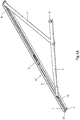
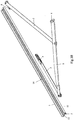
- Figs. 1A and 1B show a linkage incorporating a restrictor assembly for restricting the opening of a window.
- the window is hinged about a fixed vertical axis at one edge of the window and that the restrictor assembly is mounted on the window frame along a bottom edge of the frame.
- An elongate member 3 is slidably mounted in the track 2 for movement along the track.
- a restrictor device 4 is mounted and at the other end of the member 3 one end of a link 5 is pivotally connected.
- the other end of the link 5 carries a pin 6 which is pivotally connected to the window (not shown) whose movement is to be restricted.
- one end of a link 7 is pivotally connected, the opposite end of the link 7 being pivotally mounted on an anchor 8 that is fixed in the track 2.
- FIGs. 2 and 3 there is shown an end portion of the member 3, a portion of the track 2 and the restrictor device referenced 4 in Figs. 1A and 1B . Those parts may together be described as a restrictor assembly.
- the track 2 is of generally uniform cross-section and is defined by a base 11, side walls 12 extending upwardly from opposite side edges of the base and lips 13 at the tops of the side walls 12 and projecting inwardly from the side walls.
- the lips 13 are formed with recesses 15 to provide a castellated shape.
- the restrictor device shown in Figs. 2 and 3 generally comprises: a member 17, which in this embodiment exemplifies the "second member” of the restrictor assembly of the invention and which is mounted on the end of the member 3; a configuration-adjusting member 18, which in this embodiment exemplifies the "third member” of the restrictor assembly of the invention and which is mountable and securable on the top of the member 17; and a locking member 30 which is rotatably mounted on the member 17.
- the member 17 is connected to the member 3 in such a way that the member 17 is biased upwardly away from the base of the track. In the example shown this is achieved by providing a degree of resilience in the member 3 and having the end portion of the member 17 slightly upwardly inclined in its unstressed state. As a result the member 3 is pressed upwardly against the undersides of the lips 13.
- the member 17 is sized to be able to be received in the track 2 with most of the member 17 having a width slightly less than the separation of the lips 13 but with projections 19A, 19B and 19C on the member 17 extending further outwardly beneath the lips 13.
- the projections 19A are dimensioned and positioned to be able to be received in the recesses 15 when the restrictor device is at a predetermined position within the portion 14 of the track 2.
- the projections 19C are dimensioned and positioned to remain within the track below the lips 13 at all times.
- the projections 19A have inclined faces 20 at first ends and perpendicular faces 21 at their opposite second ends.
- the projections 19A are received in the recesses 15 of the track 2 and a longitudinal force is applied to the member 17 pressing the inclined faces 20 against end walls of the recesses 15, the faces 20 are pressed downwardly through a camming action towards the base of the track and the member 17 becomes free to slide along the track 2.
- the configuration-adjusting member 18 is sized to be able to be received in the track 2 with most of the configuration-adjusting member 18 having a width slightly less than the separation of the lips 13 but with projections 23 and 24 on the configuration-adjusting member 18 extending further outwardly beneath the lips 13 when the configuration-adjusting member 18 is secured to the member 17.
- the projections 23 are dimensioned and positioned to be able to be received in the recesses 15 when the restrictor device is at a predetermined position within the portion 14 of the track.
- the projections 24 are dimensioned and positioned to remain within the track below the lips 13.
- the configuration-adjusting member 18 is secured to the member 17 by end lugs 25 and 26 which engage in recesses in the member 17 and by a fixing means, for example a screw, 27 which fastens the configuration-adjusting member 18 to the member 17.
- the locking member 30 has a plate-like portion 31 whose longitudinal dimension, as viewed in Figs. 2 to 4 , is greater than its transverse dimension and has curved ends.
- a boss 32 is upstanding from the middle of the plate-like portion 31 and is formed with recesses 33. The boss 32 is received in a circular opening 34 in the member 17 and is thereby rotatably mounted in the member.
- the locking member 30 is retained in the rotational orientation shown in Figs. 2 to 4 by small projecting parts 35 on the end regions 36 of the ends of the plate-like portion 31 engaging in recesses (not visible in the drawings) in the member 17.
- the extent of the engagement is such that the locking member 30 is not likely to rotate through accidental contact or vibration but the member can be rotated through 90 degrees to the position shown in Fig. 5 by engaging a suitable tool in the recesses 33 in the boss 32. In this position the end regions 36 of the plate-like portion 31 project over the tops of the lips 13 of the track 2.
- the locking member also serves, when in the position shown in Figs. 2 to 4 , to retain the configuration-adjusting member 18 on the member 17 even if the fixing means 27 is removed: one of the end regions 36 of the plate-like portion 31 projects over the top of the end lug 26 preventing its withdrawal from the recess in the member 17.
- the locking member 30 is rotated to the position shown in Fig. 5 and the end lug 26 can then be withdrawn from its recess in the member 17.
- the member 17 If the configuration-adjusting member 18 is not fitted, then, once the projections 19A are received in the recesses 15, the member 17, and therefore also the member 3, are held against movement in one direction (the direction causing the confronting perpendicular faces to be pressed against each other), but will be able to move in the opposite direction with the inclined faces 20 being pressed downwardly against the upward resilient bias to a position below the lips 13 of the track 2.
- the member 3 is able to move in one direction (allowing movement of the window in that direction, which would usually be chosen to correspond to closing of the window), but is not able to move in the opposite direction.
- the holding of the restrictor device against longitudinal movement can be overridden by manually depressing the device by pressing down in a region 40 of the member 17. That pressing depresses the projections 19A, and the projections 23 in the case where the member 18 is also present, so that they are free to pass beneath the lips 13.
- the locking member 30 does not obstruct such depression when in the position shown in Figs. 2 to 4 , but does prevent such depression when in the position shown in Fig. 5 ; accordingly, with the locking member in the position shown in Fig. 5 , the member 3 is prevented from sliding along the track in either direction. In that case the window is locked and unable to be opened further or closed.
- a first choice as to whether or not to employ the configuration-adjusting member 18 is made initially. Thereafter the configuration may be changed when the restrictor device is in engagement with the castellated portion 14 of the track, but such a change of configuration will be required only if it is desired to change the restriction on opening or closing the window.
- FIG. 6 to 9 corresponding parts are referenced by the same reference numerals as in Figs. 2 to 5 .
- the configuration adjusting member 18 is always fitted to the member 17 but it can be fitted in either of two orientations that are 180 degrees apart.
- the projections 23 on the member 18 are profiled such that they interact with the projections 19A on the member 17 to provide compound projections with desired profiles.
- the effect of rotating the member 18 is to switch the inclinations of the camming surfaces from one inclination to an opposite inclination.
- the restrictor device in a first configuration is held against longitudinal movement in a first direction but not in a second opposite direction, whilst in a second configuration the restrictor device is held against longitudinal movement in the second direction but not in the first opposite direction.
- the effect of removing the member 18 is to allow movement of the members 3,17 in one direction when such movement was previously blocked, but it will be understood that one could alternatively change the shapes of the projections 19, 23, such that the effect of removing the member 18 is to prevent movement of the members 3,17 in one direction when such movement was previously allowed.
- the restrictor arrangement has been described in the context of a window pivoting about a fixed vertical axis, but it should be understood that the invention is also applicable to a window pivoting about a fixed horizontal axis and to other window arrangements which may involve only rotational movement or a combination of rotational or translational movement or only translational movement as for example would apply in the case of a sash window. Whilst in the embodiments described above, the restrictor assembly is provided for a window, it should be understood that it could be applied to another member, for example a door.
Landscapes
- Engineering & Computer Science (AREA)
- Mechanical Engineering (AREA)
- Wing Frames And Configurations (AREA)
Applications Claiming Priority (1)
| Application Number | Priority Date | Filing Date | Title |
|---|---|---|---|
| GB1602387.1A GB2547213B (en) | 2016-02-10 | 2016-02-10 | Restrictor assembly |
Publications (2)
| Publication Number | Publication Date |
|---|---|
| EP3205802A1 EP3205802A1 (en) | 2017-08-16 |
| EP3205802B1 true EP3205802B1 (en) | 2019-10-16 |
Family
ID=55642098
Family Applications (1)
| Application Number | Title | Priority Date | Filing Date |
|---|---|---|---|
| EP17275015.0A Active EP3205802B1 (en) | 2016-02-10 | 2017-02-10 | Restrictor assembly |
Country Status (4)
| Country | Link |
|---|---|
| EP (1) | EP3205802B1 (da) |
| DK (1) | DK3205802T3 (da) |
| GB (1) | GB2547213B (da) |
| HU (1) | HUE047494T2 (da) |
Families Citing this family (1)
| Publication number | Priority date | Publication date | Assignee | Title |
|---|---|---|---|---|
| IT202200001466A1 (it) * | 2022-01-28 | 2023-07-28 | Carletti S R L | Cerniera antivento per un serramento |
Family Cites Families (8)
| Publication number | Priority date | Publication date | Assignee | Title |
|---|---|---|---|---|
| GB8322400D0 (en) * | 1983-08-19 | 1983-09-21 | Shaw Mfg Ltd | Window stay |
| GB9715521D0 (en) * | 1997-07-24 | 1997-10-01 | Trojan Hardware & Designs Ltd | Hinge mechanisms for openable windows and other such movable panels |
| GB2404692B (en) * | 2000-06-05 | 2005-04-13 | Giovanni Maria Laporta | Friction hinge & window fitting |
| IE20011085A1 (en) * | 2001-12-19 | 2003-06-25 | Jurras Ltd | Friction Stay |
| GB0426419D0 (en) * | 2004-12-02 | 2005-01-05 | Avocet Hardware Ltd | Stay for hingedly mounting an openable closure member |
| GB0513066D0 (en) * | 2005-06-27 | 2005-08-03 | Securistyle Ltd | Hinges and restricting devices therefor |
| GB2429042B (en) * | 2005-08-08 | 2010-02-24 | Laird Security Hardware Ltd | Friction stays |
| GB2432189B (en) * | 2005-11-10 | 2009-11-25 | Laird Security Hardware Ltd | Stays |
-
2016
- 2016-02-10 GB GB1602387.1A patent/GB2547213B/en active Active
-
2017
- 2017-02-10 HU HUE17275015A patent/HUE047494T2/hu unknown
- 2017-02-10 EP EP17275015.0A patent/EP3205802B1/en active Active
- 2017-02-10 DK DK17275015.0T patent/DK3205802T3/da active
Non-Patent Citations (1)
| Title |
|---|
| None * |
Also Published As
| Publication number | Publication date |
|---|---|
| GB201602387D0 (en) | 2016-03-23 |
| DK3205802T3 (da) | 2020-01-27 |
| HUE047494T2 (hu) | 2020-04-28 |
| GB2547213A (en) | 2017-08-16 |
| GB2547213B (en) | 2019-07-31 |
| EP3205802A1 (en) | 2017-08-16 |
Similar Documents
| Publication | Publication Date | Title |
|---|---|---|
| EP2140090B1 (en) | Restricting devices | |
| US6779855B2 (en) | Interlock mechanism for lateral file cabinets | |
| US8627602B2 (en) | Gate assembly | |
| US20070289100A1 (en) | Casement Window Hinge | |
| CN114541896B (zh) | 门或窗的开度的限制装置 | |
| JP6823142B1 (ja) | 窓開閉ロック装置 | |
| EP3205802B1 (en) | Restrictor assembly | |
| AU2019226229B2 (en) | Window stays | |
| EP2714204A2 (en) | A safety clamp | |
| JP6037645B2 (ja) | 窓の開度制限装置 | |
| US4762161A (en) | Locking device for use with a blind assembly | |
| EP2495383B1 (en) | Slide brake for turnable windows, doors or shutters | |
| CA2411747A1 (en) | Clip lock folding operator handle | |
| JP2019078161A (ja) | 開き角度保持装置および建具 | |
| JP4426274B2 (ja) | 戸パネルの支持装置 | |
| EP3093419A1 (en) | Security device for a window | |
| JP4510137B2 (ja) | スライド操作装置並びにそれを用いた可動ルーバー窓の開閉操作装置 | |
| CA2464359C (en) | Keyboard arm | |
| JP4337068B2 (ja) | 窓のロック装置 | |
| JPH059411Y2 (da) | ||
| JP5164143B2 (ja) | シャッター装置のロック装置、及び、それを備えるシャッター装置 | |
| GB2148382A (en) | Latching mechanism | |
| JP2000204821A (ja) | 内倒し窓の障子開き状態保持装置 | |
| GB2633654A (en) | Securing formation on a window stay | |
| JPH03286078A (ja) | あおり止め |
Legal Events
| Date | Code | Title | Description |
|---|---|---|---|
| PUAI | Public reference made under article 153(3) epc to a published international application that has entered the european phase |
Free format text: ORIGINAL CODE: 0009012 |
|
| STAA | Information on the status of an ep patent application or granted ep patent |
Free format text: STATUS: THE APPLICATION HAS BEEN PUBLISHED |
|
| AK | Designated contracting states |
Kind code of ref document: A1 Designated state(s): AL AT BE BG CH CY CZ DE DK EE ES FI FR GB GR HR HU IE IS IT LI LT LU LV MC MK MT NL NO PL PT RO RS SE SI SK SM TR |
|
| AX | Request for extension of the european patent |
Extension state: BA ME |
|
| STAA | Information on the status of an ep patent application or granted ep patent |
Free format text: STATUS: REQUEST FOR EXAMINATION WAS MADE |
|
| 17P | Request for examination filed |
Effective date: 20180216 |
|
| RBV | Designated contracting states (corrected) |
Designated state(s): AL AT BE BG CH CY CZ DE DK EE ES FI FR GB GR HR HU IE IS IT LI LT LU LV MC MK MT NL NO PL PT RO RS SE SI SK SM TR |
|
| STAA | Information on the status of an ep patent application or granted ep patent |
Free format text: STATUS: EXAMINATION IS IN PROGRESS |
|
| 17Q | First examination report despatched |
Effective date: 20180704 |
|
| GRAP | Despatch of communication of intention to grant a patent |
Free format text: ORIGINAL CODE: EPIDOSNIGR1 |
|
| STAA | Information on the status of an ep patent application or granted ep patent |
Free format text: STATUS: GRANT OF PATENT IS INTENDED |
|
| INTG | Intention to grant announced |
Effective date: 20190102 |
|
| GRAJ | Information related to disapproval of communication of intention to grant by the applicant or resumption of examination proceedings by the epo deleted |
Free format text: ORIGINAL CODE: EPIDOSDIGR1 |
|
| STAA | Information on the status of an ep patent application or granted ep patent |
Free format text: STATUS: EXAMINATION IS IN PROGRESS |
|
| GRAP | Despatch of communication of intention to grant a patent |
Free format text: ORIGINAL CODE: EPIDOSNIGR1 |
|
| STAA | Information on the status of an ep patent application or granted ep patent |
Free format text: STATUS: GRANT OF PATENT IS INTENDED |
|
| INTC | Intention to grant announced (deleted) | ||
| INTG | Intention to grant announced |
Effective date: 20190221 |
|
| GRAS | Grant fee paid |
Free format text: ORIGINAL CODE: EPIDOSNIGR3 |
|
| RBV | Designated contracting states (corrected) |
Designated state(s): AL AT BE BG CH CY CZ DE DK EE ES FI FR GR HR HU IE IS IT LI LT LU LV MC MK MT NL NO PL PT RO RS SE SI SK SM TR |
|
| GRAA | (expected) grant |
Free format text: ORIGINAL CODE: 0009210 |
|
| STAA | Information on the status of an ep patent application or granted ep patent |
Free format text: STATUS: THE PATENT HAS BEEN GRANTED |
|
| AK | Designated contracting states |
Kind code of ref document: B1 Designated state(s): AL AT BE BG CH CY CZ DE DK EE ES FI FR GR HR HU IE IS IT LI LT LU LV MC MK MT NL NO PL PT RO RS SE SI SK SM TR |
|
| REG | Reference to a national code |
Ref country code: CH Ref legal event code: EP |
|
| REG | Reference to a national code |
Ref country code: DE Ref legal event code: R096 Ref document number: 602017007874 Country of ref document: DE |
|
| REG | Reference to a national code |
Ref country code: IE Ref legal event code: FG4D |
|
| REG | Reference to a national code |
Ref country code: AT Ref legal event code: REF Ref document number: 1191412 Country of ref document: AT Kind code of ref document: T Effective date: 20191115 |
|
| REG | Reference to a national code |
Ref country code: FI Ref legal event code: FGE |
|
| REG | Reference to a national code |
Ref country code: DK Ref legal event code: T3 Effective date: 20200123 |
|
| REG | Reference to a national code |
Ref country code: SE Ref legal event code: TRGR |
|
| REG | Reference to a national code |
Ref country code: NL Ref legal event code: MP Effective date: 20191016 |
|
| REG | Reference to a national code |
Ref country code: NO Ref legal event code: T2 Effective date: 20191016 |
|
| REG | Reference to a national code |
Ref country code: LT Ref legal event code: MG4D |
|
| REG | Reference to a national code |
Ref country code: AT Ref legal event code: MK05 Ref document number: 1191412 Country of ref document: AT Kind code of ref document: T Effective date: 20191016 |
|
| REG | Reference to a national code |
Ref country code: HU Ref legal event code: AG4A Ref document number: E047494 Country of ref document: HU |
|
| PG25 | Lapsed in a contracting state [announced via postgrant information from national office to epo] |
Ref country code: NL Free format text: LAPSE BECAUSE OF FAILURE TO SUBMIT A TRANSLATION OF THE DESCRIPTION OR TO PAY THE FEE WITHIN THE PRESCRIBED TIME-LIMIT Effective date: 20191016 Ref country code: AT Free format text: LAPSE BECAUSE OF FAILURE TO SUBMIT A TRANSLATION OF THE DESCRIPTION OR TO PAY THE FEE WITHIN THE PRESCRIBED TIME-LIMIT Effective date: 20191016 Ref country code: LV Free format text: LAPSE BECAUSE OF FAILURE TO SUBMIT A TRANSLATION OF THE DESCRIPTION OR TO PAY THE FEE WITHIN THE PRESCRIBED TIME-LIMIT Effective date: 20191016 Ref country code: PT Free format text: LAPSE BECAUSE OF FAILURE TO SUBMIT A TRANSLATION OF THE DESCRIPTION OR TO PAY THE FEE WITHIN THE PRESCRIBED TIME-LIMIT Effective date: 20200217 Ref country code: LT Free format text: LAPSE BECAUSE OF FAILURE TO SUBMIT A TRANSLATION OF THE DESCRIPTION OR TO PAY THE FEE WITHIN THE PRESCRIBED TIME-LIMIT Effective date: 20191016 Ref country code: PL Free format text: LAPSE BECAUSE OF FAILURE TO SUBMIT A TRANSLATION OF THE DESCRIPTION OR TO PAY THE FEE WITHIN THE PRESCRIBED TIME-LIMIT Effective date: 20191016 Ref country code: BG Free format text: LAPSE BECAUSE OF FAILURE TO SUBMIT A TRANSLATION OF THE DESCRIPTION OR TO PAY THE FEE WITHIN THE PRESCRIBED TIME-LIMIT Effective date: 20200116 Ref country code: GR Free format text: LAPSE BECAUSE OF FAILURE TO SUBMIT A TRANSLATION OF THE DESCRIPTION OR TO PAY THE FEE WITHIN THE PRESCRIBED TIME-LIMIT Effective date: 20200117 |
|
| PG25 | Lapsed in a contracting state [announced via postgrant information from national office to epo] |
Ref country code: RS Free format text: LAPSE BECAUSE OF FAILURE TO SUBMIT A TRANSLATION OF THE DESCRIPTION OR TO PAY THE FEE WITHIN THE PRESCRIBED TIME-LIMIT Effective date: 20191016 Ref country code: HR Free format text: LAPSE BECAUSE OF FAILURE TO SUBMIT A TRANSLATION OF THE DESCRIPTION OR TO PAY THE FEE WITHIN THE PRESCRIBED TIME-LIMIT Effective date: 20191016 Ref country code: IS Free format text: LAPSE BECAUSE OF FAILURE TO SUBMIT A TRANSLATION OF THE DESCRIPTION OR TO PAY THE FEE WITHIN THE PRESCRIBED TIME-LIMIT Effective date: 20200224 |
|
| PG25 | Lapsed in a contracting state [announced via postgrant information from national office to epo] |
Ref country code: AL Free format text: LAPSE BECAUSE OF FAILURE TO SUBMIT A TRANSLATION OF THE DESCRIPTION OR TO PAY THE FEE WITHIN THE PRESCRIBED TIME-LIMIT Effective date: 20191016 |
|
| REG | Reference to a national code |
Ref country code: DE Ref legal event code: R097 Ref document number: 602017007874 Country of ref document: DE |
|
| PG2D | Information on lapse in contracting state deleted |
Ref country code: IS |
|
| PG25 | Lapsed in a contracting state [announced via postgrant information from national office to epo] |
Ref country code: IS Free format text: LAPSE BECAUSE OF FAILURE TO SUBMIT A TRANSLATION OF THE DESCRIPTION OR TO PAY THE FEE WITHIN THE PRESCRIBED TIME-LIMIT Effective date: 20200216 Ref country code: CZ Free format text: LAPSE BECAUSE OF FAILURE TO SUBMIT A TRANSLATION OF THE DESCRIPTION OR TO PAY THE FEE WITHIN THE PRESCRIBED TIME-LIMIT Effective date: 20191016 Ref country code: RO Free format text: LAPSE BECAUSE OF FAILURE TO SUBMIT A TRANSLATION OF THE DESCRIPTION OR TO PAY THE FEE WITHIN THE PRESCRIBED TIME-LIMIT Effective date: 20191016 Ref country code: EE Free format text: LAPSE BECAUSE OF FAILURE TO SUBMIT A TRANSLATION OF THE DESCRIPTION OR TO PAY THE FEE WITHIN THE PRESCRIBED TIME-LIMIT Effective date: 20191016 Ref country code: ES Free format text: LAPSE BECAUSE OF FAILURE TO SUBMIT A TRANSLATION OF THE DESCRIPTION OR TO PAY THE FEE WITHIN THE PRESCRIBED TIME-LIMIT Effective date: 20191016 |
|
| PLBE | No opposition filed within time limit |
Free format text: ORIGINAL CODE: 0009261 |
|
| STAA | Information on the status of an ep patent application or granted ep patent |
Free format text: STATUS: NO OPPOSITION FILED WITHIN TIME LIMIT |
|
| PG25 | Lapsed in a contracting state [announced via postgrant information from national office to epo] |
Ref country code: SK Free format text: LAPSE BECAUSE OF FAILURE TO SUBMIT A TRANSLATION OF THE DESCRIPTION OR TO PAY THE FEE WITHIN THE PRESCRIBED TIME-LIMIT Effective date: 20191016 Ref country code: SM Free format text: LAPSE BECAUSE OF FAILURE TO SUBMIT A TRANSLATION OF THE DESCRIPTION OR TO PAY THE FEE WITHIN THE PRESCRIBED TIME-LIMIT Effective date: 20191016 Ref country code: IT Free format text: LAPSE BECAUSE OF FAILURE TO SUBMIT A TRANSLATION OF THE DESCRIPTION OR TO PAY THE FEE WITHIN THE PRESCRIBED TIME-LIMIT Effective date: 20191016 |
|
| REG | Reference to a national code |
Ref country code: DE Ref legal event code: R119 Ref document number: 602017007874 Country of ref document: DE |
|
| REG | Reference to a national code |
Ref country code: FI Ref legal event code: MAE |
|
| REG | Reference to a national code |
Ref country code: DK Ref legal event code: EBP Effective date: 20200229 |
|
| 26N | No opposition filed |
Effective date: 20200717 |
|
| REG | Reference to a national code |
Ref country code: SE Ref legal event code: EUG |
|
| REG | Reference to a national code |
Ref country code: CH Ref legal event code: PL |
|
| REG | Reference to a national code |
Ref country code: BE Ref legal event code: MM Effective date: 20200229 |
|
| PG25 | Lapsed in a contracting state [announced via postgrant information from national office to epo] |
Ref country code: LU Free format text: LAPSE BECAUSE OF NON-PAYMENT OF DUE FEES Effective date: 20200210 Ref country code: SE Free format text: LAPSE BECAUSE OF NON-PAYMENT OF DUE FEES Effective date: 20200211 Ref country code: MC Free format text: LAPSE BECAUSE OF FAILURE TO SUBMIT A TRANSLATION OF THE DESCRIPTION OR TO PAY THE FEE WITHIN THE PRESCRIBED TIME-LIMIT Effective date: 20191016 Ref country code: FI Free format text: LAPSE BECAUSE OF NON-PAYMENT OF DUE FEES Effective date: 20200210 |
|
| PG25 | Lapsed in a contracting state [announced via postgrant information from national office to epo] |
Ref country code: SI Free format text: LAPSE BECAUSE OF FAILURE TO SUBMIT A TRANSLATION OF THE DESCRIPTION OR TO PAY THE FEE WITHIN THE PRESCRIBED TIME-LIMIT Effective date: 20191016 Ref country code: LI Free format text: LAPSE BECAUSE OF NON-PAYMENT OF DUE FEES Effective date: 20200229 Ref country code: CH Free format text: LAPSE BECAUSE OF NON-PAYMENT OF DUE FEES Effective date: 20200229 Ref country code: HU Free format text: LAPSE BECAUSE OF NON-PAYMENT OF DUE FEES Effective date: 20200211 |
|
| PG25 | Lapsed in a contracting state [announced via postgrant information from national office to epo] |
Ref country code: DE Free format text: LAPSE BECAUSE OF NON-PAYMENT OF DUE FEES Effective date: 20200901 Ref country code: IE Free format text: LAPSE BECAUSE OF NON-PAYMENT OF DUE FEES Effective date: 20200210 Ref country code: FR Free format text: LAPSE BECAUSE OF NON-PAYMENT OF DUE FEES Effective date: 20200229 Ref country code: DK Free format text: LAPSE BECAUSE OF NON-PAYMENT OF DUE FEES Effective date: 20200229 |
|
| PG25 | Lapsed in a contracting state [announced via postgrant information from national office to epo] |
Ref country code: BE Free format text: LAPSE BECAUSE OF NON-PAYMENT OF DUE FEES Effective date: 20200229 |
|
| REG | Reference to a national code |
Ref country code: NO Ref legal event code: MMEP |
|
| PG25 | Lapsed in a contracting state [announced via postgrant information from national office to epo] |
Ref country code: NO Free format text: LAPSE BECAUSE OF NON-PAYMENT OF DUE FEES Effective date: 20210228 |
|
| PG25 | Lapsed in a contracting state [announced via postgrant information from national office to epo] |
Ref country code: HU Free format text: LAPSE BECAUSE OF NON-PAYMENT OF DUE FEES Effective date: 20200211 |
|
| PGRI | Patent reinstated in contracting state [announced from national office to epo] |
Ref country code: HU Effective date: 20211102 |
|
| PGFP | Annual fee paid to national office [announced via postgrant information from national office to epo] |
Ref country code: HU Payment date: 20211024 Year of fee payment: 5 |
|
| PG25 | Lapsed in a contracting state [announced via postgrant information from national office to epo] |
Ref country code: TR Free format text: LAPSE BECAUSE OF FAILURE TO SUBMIT A TRANSLATION OF THE DESCRIPTION OR TO PAY THE FEE WITHIN THE PRESCRIBED TIME-LIMIT Effective date: 20191016 Ref country code: MT Free format text: LAPSE BECAUSE OF FAILURE TO SUBMIT A TRANSLATION OF THE DESCRIPTION OR TO PAY THE FEE WITHIN THE PRESCRIBED TIME-LIMIT Effective date: 20191016 Ref country code: CY Free format text: LAPSE BECAUSE OF FAILURE TO SUBMIT A TRANSLATION OF THE DESCRIPTION OR TO PAY THE FEE WITHIN THE PRESCRIBED TIME-LIMIT Effective date: 20191016 |
|
| PG25 | Lapsed in a contracting state [announced via postgrant information from national office to epo] |
Ref country code: MK Free format text: LAPSE BECAUSE OF FAILURE TO SUBMIT A TRANSLATION OF THE DESCRIPTION OR TO PAY THE FEE WITHIN THE PRESCRIBED TIME-LIMIT Effective date: 20191016 |
|
| PG25 | Lapsed in a contracting state [announced via postgrant information from national office to epo] |
Ref country code: HU Free format text: LAPSE BECAUSE OF NON-PAYMENT OF DUE FEES Effective date: 20220211 |
|
| PG25 | Lapsed in a contracting state [announced via postgrant information from national office to epo] |
Ref country code: NO Free format text: LAPSE BECAUSE OF NON-PAYMENT OF DUE FEES Effective date: 20240229 |
|
| PG25 | Lapsed in a contracting state [announced via postgrant information from national office to epo] |
Ref country code: NO Free format text: LAPSE BECAUSE OF NON-PAYMENT OF DUE FEES Effective date: 20240229 |
|
| PGRI | Patent reinstated in contracting state [announced from national office to epo] |
Ref country code: NO Effective date: 20241126 |
|
| PG25 | Lapsed in a contracting state [announced via postgrant information from national office to epo] |
Ref country code: NO Free format text: LAPSE BECAUSE OF NON-PAYMENT OF DUE FEES Effective date: 20240229 |
|
| PGRI | Patent reinstated in contracting state [announced from national office to epo] |
Ref country code: NO Effective date: 20241126 |
|
| PGFP | Annual fee paid to national office [announced via postgrant information from national office to epo] |
Ref country code: NO Payment date: 20250714 Year of fee payment: 9 |