EP3205584A1 - Äussere flugzeugbeleuchtung und flugzeug damit - Google Patents
Äussere flugzeugbeleuchtung und flugzeug damit Download PDFInfo
- Publication number
- EP3205584A1 EP3205584A1 EP17153937.2A EP17153937A EP3205584A1 EP 3205584 A1 EP3205584 A1 EP 3205584A1 EP 17153937 A EP17153937 A EP 17153937A EP 3205584 A1 EP3205584 A1 EP 3205584A1
- Authority
- EP
- European Patent Office
- Prior art keywords
- mounting board
- light
- exterior aircraft
- lens structure
- enclosure
- Prior art date
- Legal status (The legal status is an assumption and is not a legal conclusion. Google has not performed a legal analysis and makes no representation as to the accuracy of the status listed.)
- Granted
Links
Images

Classifications
-
- B—PERFORMING OPERATIONS; TRANSPORTING
- B64—AIRCRAFT; AVIATION; COSMONAUTICS
- B64D—EQUIPMENT FOR FITTING IN OR TO AIRCRAFT; FLIGHT SUITS; PARACHUTES; ARRANGEMENT OR MOUNTING OF POWER PLANTS OR PROPULSION TRANSMISSIONS IN AIRCRAFT
- B64D47/00—Equipment not otherwise provided for
- B64D47/02—Arrangements or adaptations of signal or lighting devices
- B64D47/06—Arrangements or adaptations of signal or lighting devices for indicating aircraft presence
-
- B—PERFORMING OPERATIONS; TRANSPORTING
- B64—AIRCRAFT; AVIATION; COSMONAUTICS
- B64D—EQUIPMENT FOR FITTING IN OR TO AIRCRAFT; FLIGHT SUITS; PARACHUTES; ARRANGEMENT OR MOUNTING OF POWER PLANTS OR PROPULSION TRANSMISSIONS IN AIRCRAFT
- B64D47/00—Equipment not otherwise provided for
- B64D47/02—Arrangements or adaptations of signal or lighting devices
- B64D47/04—Arrangements or adaptations of signal or lighting devices the lighting devices being primarily intended to illuminate the way ahead
-
- F—MECHANICAL ENGINEERING; LIGHTING; HEATING; WEAPONS; BLASTING
- F21—LIGHTING
- F21V—FUNCTIONAL FEATURES OR DETAILS OF LIGHTING DEVICES OR SYSTEMS THEREOF; STRUCTURAL COMBINATIONS OF LIGHTING DEVICES WITH OTHER ARTICLES, NOT OTHERWISE PROVIDED FOR
- F21V19/00—Fastening of light sources or lamp holders
- F21V19/001—Fastening of light sources or lamp holders the light sources being semiconductors devices, e.g. LEDs
- F21V19/0015—Fastening arrangements intended to retain light sources
- F21V19/002—Fastening arrangements intended to retain light sources the fastening means engaging the encapsulation or the packaging of the semiconductor device
-
- F—MECHANICAL ENGINEERING; LIGHTING; HEATING; WEAPONS; BLASTING
- F21—LIGHTING
- F21V—FUNCTIONAL FEATURES OR DETAILS OF LIGHTING DEVICES OR SYSTEMS THEREOF; STRUCTURAL COMBINATIONS OF LIGHTING DEVICES WITH OTHER ARTICLES, NOT OTHERWISE PROVIDED FOR
- F21V5/00—Refractors for light sources
- F21V5/04—Refractors for light sources of lens shape
-
- F—MECHANICAL ENGINEERING; LIGHTING; HEATING; WEAPONS; BLASTING
- F21—LIGHTING
- F21V—FUNCTIONAL FEATURES OR DETAILS OF LIGHTING DEVICES OR SYSTEMS THEREOF; STRUCTURAL COMBINATIONS OF LIGHTING DEVICES WITH OTHER ARTICLES, NOT OTHERWISE PROVIDED FOR
- F21V7/00—Reflectors for light sources
- F21V7/0091—Reflectors for light sources using total internal reflection
-
- H—ELECTRICITY
- H05—ELECTRIC TECHNIQUES NOT OTHERWISE PROVIDED FOR
- H05B—ELECTRIC HEATING; ELECTRIC LIGHT SOURCES NOT OTHERWISE PROVIDED FOR; CIRCUIT ARRANGEMENTS FOR ELECTRIC LIGHT SOURCES, IN GENERAL
- H05B47/00—Circuit arrangements for operating light sources in general, i.e. where the type of light source is not relevant
- H05B47/20—Responsive to malfunctions or to light source life; for protection
- H05B47/24—Circuit arrangements for protecting against overvoltage
-
- B—PERFORMING OPERATIONS; TRANSPORTING
- B64—AIRCRAFT; AVIATION; COSMONAUTICS
- B64D—EQUIPMENT FOR FITTING IN OR TO AIRCRAFT; FLIGHT SUITS; PARACHUTES; ARRANGEMENT OR MOUNTING OF POWER PLANTS OR PROPULSION TRANSMISSIONS IN AIRCRAFT
- B64D2203/00—Aircraft or airfield lights using LEDs
-
- F—MECHANICAL ENGINEERING; LIGHTING; HEATING; WEAPONS; BLASTING
- F21—LIGHTING
- F21Y—INDEXING SCHEME ASSOCIATED WITH SUBCLASSES F21K, F21L, F21S and F21V, RELATING TO THE FORM OR THE KIND OF THE LIGHT SOURCES OR OF THE COLOUR OF THE LIGHT EMITTED
- F21Y2115/00—Light-generating elements of semiconductor light sources
- F21Y2115/10—Light-emitting diodes [LED]
Definitions
- the present invention relates to exterior aircraft lighting.
- exterior aircraft lights that employ one or more LEDs as light sources, which are mounted to a mounting board, such as a printed circuit board (PCB).
- PCB printed circuit board
- Exterior lights Almost all aircraft are equipped with exterior lights.
- large passenger air planes are provided with a wide variety of exterior lights.
- the exterior lights are provided for various different purposes, such as for allowing the passengers and/or air crew to view the outside, for passive visibility, for signalling purposes, etc.
- Examples of such exterior lights are navigation lights, also referred to as position lights, anti-collision lights, landing lights, taxi lights, runway turn-off lights, etc.
- LEDs are a potential kind of light source for exterior aircraft lights. They are commonly mounted on a mounting board that is adapted for the arrangement and connection of electronic components. Such mounting board may be a printed circuit board (PCB).
- PCB printed circuit board
- ESD electrostatic discharge
- heat may be built up at the printed circuit board during operation.
- the foregoing issues are particularly severe in exterior aircraft lights, as they are required to operate in very hazardous conditions. Depending on their location on the aircraft, they may have to withstand large aerodynamic forces, strong vibrations, large temperature variations and/or hazardous gases, such as exhaust fumes. Addressing these issues has lead to complicated designs for exterior aircraft lights in the past, resulting in complicated and lengthy production procedures.
- Exemplary embodiments of the invention include an exterior aircraft light, comprising a mounting board, having an upper side, a lower side and a plurality of side faces; at least one LED, arranged on the upper side of the mounting board; and a mounting board enclosure and lens structure, wherein the mounting board enclosure and lens structure comprises a lens arranged over the at least one LED for shaping an output light intensity distribution of the exterior aircraft light and a covering layer arranged on the upper side, the lower side and the plurality of side faces of the mounting board, wherein the mounting board enclosure and lens structure is an integral silicone structure.
- Exemplary embodiments of the invention allow for the integration of the conditioning of the output light intensity distribution, the electrostatic discharge (ESD) protection, and the heat transport away from the mounting board into a single structure.
- the lens is formed in the mounting board enclosure and lens structure, which is an integral silicone structure, such that a desired output light intensity distribution can be achieved with a structure that simultaneously serves further purposes.
- the part of the covering layer arranged on the upper side of the mounting board is an effective means of preventing electrostatic discharge from the electric connectors of the mounting board and, potentially, other electronic components.
- the part of the covering layer arranged on the lower side of the mounting board provides for an effective means of conducting heat, which is generated during the operation of the at least one LED and, potentially, other electronic components, away from the mounting board.
- this integral silicone structure can be applied to the mounting board as a single element in a single step of the manufacturing process.
- multiple issues of LED-based exterior aircraft lights can be addressed in a single manufacturing step, eliminating the need for separate manufacturing steps and reducing the number components required for making the mounting board and the associated at least one LED ready to use in an exterior aircraft light.
- electrostatic discharge catching elements and/or potting for wiring and/or thermal pads for heat conduction may be eliminated due to the provision of the mounting board enclosure and lens structure.
- the integral silicone structure is from a transparent silicone, thus providing a lens of high optical efficiency and thus helping in providing high light intensities, as required in various exterior aircraft lighting applications.
- Silicone is as suitable material for the mounting board enclosure and lens structure for the additional reasons that it is easily moldable and conveniently applicable to the mounting board due to its elasticity.
- the integral silicone structure is a contiguous element that reaches around the mounting board and covers all sides thereof. In particular, there are no distinct elements covering the opposite upper and lower sides of the mounting board.
- the mounting enclosure and lens structure reaches around the side faces of the mounting board for forming a single-piece integral silicone structure.
- An exemplary kind of silicone may be a so-called liquid silicone rubber.
- a particular example of an exemplary kind of silicone is Dow Corning ® MS-0002 Moldable Silicone.
- upper side, lower side and side faces of the mounting board are used in order to express the relative relationship between those elements, such as the upper side and lower side being opposite sides of the mounting board. It is pointed out that these terms do not characterize the orientation of the exterior aircraft light in use,when assembled to the aircraft. Rather, the upper side of the mounting board is defined as the side carrying the at least one LED and, potentially, other electronic components. In case the mounting board is a generally quadratic or rectangular structure, it has four side faces. However it also possible that the mounting board has a smaller or larger number of side faces, depending on the general geometric shape thereof. The upper side and the lower side are generally the sides of greatest extension of the mounting board.
- the mounting board may be a printed circuit board or other suitable kind of mounting board that is adequate for carrying the at least one LED, and, potentially, other circuit elements / components.
- a printed circuit board is a convenient way of providing electric connections to / from the at least one LED, such as to / from a power supply, a control unit, etc.
- the mounting board enclosure and lens structure fully encloses the mounting board and the at least one LED.
- the mounting board enclosure and lens structure has no edges where covered portions of the mounting board are adjacent to uncovered portions of the mounting board. By avoiding such edges between covered and uncovered portions, the danger of the mounting board enclosure and lens structure peeling off the mounting board is greatly reduced.
- the term of the mounting board enclosure and lens structure fully enclosing the mounting board and the at least one LED refers to the mounting board enclosure and lens structure covering at least all parts of the mounting board and the at least one LED that would otherwise be uncovered from other mechanical structures.
- the mounting board enclosure and lens structure is overmolded over the mounting board and the at least one LED.
- the mounting board enclosure and lens structure may be shaped into the desired shape and attached to the mounting board in a single molding operation, thus allowing for efficient production thereof.
- the exterior aircraft light may have further circuit components, such as a near end off light detector for the at least one LED, a control unit for the at least one LED, a power supply circuit for the at least one LED, etc.
- the mounting board may be provided with electric conductors, such as wires, for connecting the at least one LED to these further circuit elements and/or for connecting these further circuit elements to each other.
- the mounting board enclosure and lens structure may be overmolded over these further circuit elements as well, thus electrically isolating the components from each other and preventing electrostatic discharge.
- the mounting board enclosure and lens structure is from a soft silicone.
- the mounting board enclosure and lens structure is from a silicone with a Shore hardness of between 10A and 80A.
- the exterior aircraft light further comprises a gas impermeable coating, coated over the mounting board enclosure and lens structure.
- a gas impermeable coating may also form a corset or sandwich structure, together with the mounting board, for the mounting board enclosure and lens structure, thus increasing the stability thereof.
- Such a corset may ensure that the mounting board enclosure and lens structure stays in place, in particular in highly demanding situations, such as in high acceleration and high vibration scenarios during take-off or landing of the aircraft. High accelerations may in particular be present in the exterior aircraft lights in the wing tips of an aircraft.
- Such a corset may be particularly beneficial in the case of the mounting board enclosure and lens structure being made from a soft silicone.
- the mounting board and the gas impermeable coating may be much harder than the soft silicone, in particular more than 10 times as hard.
- the gas impermeable coating is a parylene coating.
- Parylene is particularly suitable as gas impermeable coating, because it is highly resistant to corrosive gases and it has large inherent stability for providing a shell / corset for the mounting board enclosure and lens structure. Parylene may act as a gas, moisture and dielectric barrier. Chemically, parylene is a vapour deposition of poly-xylylene. Exemplary kinds of parylene are Parylene N, SF, HT, AF-4, etc.
- the covering layer has a top portion, arranged on the upper side of the mounting board, wherein the top portion has a thickness of between 0.25 mm and 2.5 mm.
- the top portion may have a thickness of between 1 mm and 2 mm.
- the covering layer has a bottom portion arranged on the lower side of the mounting board, wherein the bottom portion has a thickness of between 0.5 mm and 4 mm, in particular of between 1 mm and 3 mm.
- the bottom portion of the covering layer is particularly suitable for providing good thermal conduction and for having sufficient thickness for evening out the lower side of the mounting board. Due to the latter effect, the mounting board can be attached to a supporting structure, such as to an exterior aircraft light housing, without substantial air enclosures between the bottom portion of the covering layer and the supporting structure.
- the bottom portion may effectively assume the functionality that was previously effected by a thermal pad/thermal grease underneath the mounting board, which may therefore be eliminated.
- Exemplary embodiments of the invention further include an exterior aircraft light, comprising a mounting board, having an upper side, a lower side and a plurality of side faces; at least one LED, arranged on the upper side of the mounting board; and a mounting board enclosure and lens structure, wherein the mounting board enclosure and lens structure comprises a lens arranged over the at least one LED for shaping an output light intensity distribution of the exterior aircraft light and a covering layer arranged on the upper side, the lower side and the plurality of side faces of the mounting board, wherein the lens and a first portion of the covering layer are from silicone and wherein a second portion of the covering layer is from a filler material.
- Embodiments with the lens and the first portion of the covering layer being from silicone and the second portion of the covering layer being from a filler material are an alternative to above described embodiments with the entire mounting board enclosure and lens structure, i.e. with both the lens and the entire covering layer, being an integral silicone structure.
- Beneficial effects, such as electrostatic discharge protection, thermal conductivity, and high integration and manufacturing efficiency, may also be achieved in this alternative manner.
- the first portion of the covering layer and the second portion of the covering layer may have the same thickness or may different thicknesses. In other words, it is possible that the transition from the first portion to the second portion of the covering layer is flush or that a noticeable change in geometry is present at the transition.
- the filler material is referred to as filler material, because it fills the gaps in the silicone part of the mounting board enclosure and lens structure.
- the first portion of the covering layer is arranged on the upper side, the plurality of side faces, and part of the lower side of the mounting board.
- the second portion of the covering layer may be arranged on another part of the lower side of the mounting board. In this way, silicone may be saved on the lower side of the mounting board, where a smaller amount of silicone may be sufficient for providing a desired thermal conductivity.
- the mounting board enclosure and lens structure fully encloses the mounting board and the at least one LED.
- either the lens or the first portion of the covering layer or the second portion of the covering layer is present at every part of the mounting board and its associated electronic components, including the at least one LED.
- either the silicone part or the filler material part of the mounting board enclosure and lens structure is present at every part of the mounting board and its associated electronic components.
- the filler material is parylene.
- the filler material may also be any other material that is suitable for covering a part of the mounting board in between the gaps of the silicone of the first portion of the covering layer.
- the exterior aircraft light further comprises a gas impermeable coating, coated over the lens and the first portion of the covering layer.
- the gas impermeable coating may be a parylene coating.
- the exterior aircraft light is one of a navigation light, an anti-collision light, a landing light, a runway turnoff light, a taxi light, and a logo light.
- the navigation light may be a forward navigation light, such as a forward navigation light arranged in a wing tip, or a tail navigation light.
- the anti-collision light may be a wing tip anti-collision light or a tail anti-collision light.
- the gas impermeable coating is particularly helpful in protecting the mounting board enclosure and lens structure from exhaust gases from an auxiliary power unit (APU).
- Exemplary embodiments of the invention further include an aircraft, comprising at least one exterior aircraft light, as described in any of the embodiments above, arranged on an outside of the aircraft.
- the modification, additional features, and effects discussed above with respect to the embodiments of the exterior aircraft light equally apply to the aircraft as a whole.
- the aircraft may for example by an air plane or a helicopter.
- Fig. 1 shows an aircraft 100 in accordance with an exemplary embodiment of the invention.
- the aircraft 100 is equipped with a forward navigation light 2, positioned in a left wing tip of the aircraft 100.
- the forward navigation light 2 is an exterior aircraft light in accordance with an exemplary embodiment of the invention. Only half of the aircraft 100 is depicted in Fig. 1 . It is understood that the aircraft 100 is substantially symmetric with respect to its axis of longitudinal extension 102. Hence, a symmetric forward navigation light in accordance with an exemplary embodiment of the invention is provided in the right wing tip as well.
- the axis of longitudinal extension 102 is also the forward flight direction of the aircraft 100, when air borne.
- the forward navigation light 2 has an output light emission distribution 104 over an angular region of 110° in a horizontal cross-sectional plane through the forward navigation light 2.
- the output light emission distribution 104 extends over an angular region from straight ahead, i.e. from the forward flight direction, to an angle of 110° counterclockwise.
- the output light emission distribution has three distinct output regions, namely a peak light intensity region between the forward flight direction of the aircraft and an angle of 10° therewith, a medium light intensity region between 10° and 20°, and a low light intensity region between 20° and 110°.
- the output light intensity is 40 cd in the peak light intensity region, 30 cd in the medium light intensity region, and 5 cd in the low light intensity region.
- the forward navigation light 2 is in compliance with Federal Aviation Regulation (FAR) requirements for forward navigation lights.
- FAR Federal Aviation Regulation
- Fig. 2 shows an exterior aircraft light 2 in accordance with an exemplary embodiment of the invention in a perspective view.
- the exterior aircraft light 2 may be used as the forward navigation light 2 of the aircraft 100, depicted in Fig. 1 .
- the exterior aircraft light 2 comprises a mounting board 4 and an LED 6.
- the LED 6 is arranged substantially at the center of the mounting board 4.
- the mounting board 4 is a printed circuit board (PCB).
- the exterior aircraft light 2 further comprises four additional circuit components 10.
- the four additional circuit components 10 are a power supply circuit for controlling the drive current to the LED 6, a sensor for measuring relative luminous flux, and two indicator LEDs for indicating near end of life to service personnel. It is also possible that other circuit components, such as a control circuit and power storage circuits, for example capacitor circuits, are present.
- These additional circuit components 10 are provided for receiving power from a power supply, temporarily storing power and for supplying power to the LED 6 and for controlling the LED 6.
- Electric connectors are provided on the mounting board 4 that interconnect the LED 6 and the additional circuit components 10.
- the mounting board 4 When used as the forward navigation light 2 of the aircraft 100 of Fig. 1 , the mounting board 4 my be arranged vertically, with the main light emission direction of the LED 6, i.e. the direction perpendicular to the mounting board 4 through the LED 6, being angled with respect to the forward flight direction of the aircraft 100.
- the exterior aircraft light 2 further comprises a mounting board enclosure and lens structure 8.
- the mounting board enclosure and lens structure 8 is a one-piece silicone structure, also referred to as an integral silicone structure.
- the mounting board enclosure and lens structure 8 both encloses the mounting board with a silicone layer and forms a lens out of silicone arranged over the LED 6.
- the mounting board enclosure and lens structure 8 is comprised of a lens 82, arranged over the LED 6, and a covering layer, which in turn is comprised of a top portion 84, a bottom portion 86, and side portions 88.
- the top portion 84 of the covering layer is arranged on the upper side of the mounting board 4, i.e. on the side of the mounting board 4 that supports the LED 6.
- the bottom portion 86 of the covering layer is arranged on the lower side of the mounting board 4, i.e. on the side of the mounting board 4 that is opposite the LED 6.
- the side portions 88 of the covering layer are arranged on the side faces of the mounting board 4.
- the mounting board 4 is a plate-like, generally quadratic structure, the side faces are much smaller in extension than the upper and lower sides of the mounting board 4.
- the mounting board enclosure and lens structure 8 fully encloses the mounting board 4 and the LED 6.
- the mounting board enclosure and lens structure 8 fully surrounds the mounting board 4 and the LED 6, i.e. it covers the entire upper and lower sides as well as the side faces of the mounting board 4.
- the mounting board enclosure and lens structure 8 also encloses the four additional circuit components 10.
- the mounting board 4 and the LED 6 are completely encased by the mounting board enclosure and lens structure 8.
- a plurality of LEDs may be provided instead of the single LED 6 of the exemplary embodiment.
- a one-dimensional or two-dimensional array of LEDs may be provided. The number and arrangement of LEDs may depend on the light intensity requirements of the particular application.
- the mounting board 4 further comprises four through holes 12.
- the four through holes 12 are also covered by the mounting board enclosure and lens structure 8.
- screws or bolts may be introduced through the through holes 12 for fastening the mounting plate 4.
- the through holes 12 are left free of silicone from the mounting board enclosure and lens structure 8.
- the mounting board 4 and the LED 6 would still be considered fully enclosed, because the through holes would be filled with the screws during assembly of the exterior aircraft light. Still, no portion of the mounting board 4 or the LED 6 would be non-covered in the assembled state.
- the mounting board 4 also comprises a slit 14, reaching through the mounting board 4 on one side of the LED 6.
- This slit 14 is configured to receive a near end of life detector.
- This near end of life detector may also be coupled to the control unit described above.
- the near end of life detector may capture some of the light emitted by the LED 6 and may deduce a state of degradation of the LED 6. It is therefore able to detect and indicate a near end of life condition. It is also possible that the near end of life detector is also arranged on the mounting board 4 and also enclosed by the mounting board enclosure and lens structure 8.
- the mounting board enclosure and lens structure 8 of the exemplary embodiment of Fig. 2 is from a soft silicone material.
- the soft silicone material is overmolded over the mounting board 4, the LED 6, and the additional circuit components 10.
- the mounting board enclosure and lens structure 8 is produced via a molding operation onto the mounting board 4, the LED 6, and the additional circuit components 10.
- Fig. 3 shows a cross-sectional view through the exterior aircraft light 2 of Fig. 2 .
- the cross-sectional plane of Fig. 3 is a plane perpendicular to the plane of extension of the plate-like mounting board 4.
- the viewing direction of Fig. 3 is indicated by arrows A-A in Fig. 2 .
- Fig. 3a and 3b both show the same exterior aircraft light 2.
- Fig. 3a shows the exterior aircraft light 2 without any light rays.
- Fig. 3b shows the exterior aircraft light 2 with some exemplary light rays.
- the through holes 12 and the slit 14 are not shown in Fig. 3 .
- the mounting board enclosure and lens structure 8 fully encloses the mounting board 4, the LED 6, and the additional circuit components 10, two of which are shown in Fig. 3 , one in the cross-sectional plane of Fig. 3 and one behind the cross-sectional plane of Fig. 3 .
- the mounting board enclosure and lens structure 8 forms a lens 82 that has a substantial height above the mounting board 4. Its extension in the direction perpendicular to the mounting board 4 is about half of the extension of the mounting board 4 in its plane of extension in the cross-sectional view of Fig. 3 .
- the top portion 84 of the covering layer of the mounting board enclosure and lens structure 8 covers the upper side of the mounting board 4.
- the top portion 84 insulates these electrical connectors as well as the LED and the additional circuit components 10. In this way, the top portion 84 provides for an effective protection of electrostatic discharge.
- the top portion may have a height of about 1.5 mm, thus providing effective electrostatic discharge protection up to high voltages.
- the bottom portion 86 of the covering layer of the mounting board enclosure and lens structure 8 covers the lower side of the mounting board 4. It provides a structure of effective heat transport away from the mounting board 4. In particular, it provides a heat bridge between the mounting board 4 and a support structure, such as a housing, to which the mounting board is fastened. In this way, the heat generated during operation of the exterior aircraft light can be effectively transported from the mounting board 4 to the housing, which acts as a heat sink.
- the side portions 88 of the covering layer of the mounting board enclosure and lens structure 8 connect the top portion 84 to the bottom portion 86. In this way, a full enclosure of the mounting board 4 and the LED 6 is achieved.
- the mounting board enclosure and lens structure 8 does not have any free edge. Hence, no point of the mounting board enclosure and lens structure 8 poses a great danger of starting to peel off of the mounting board 4 inadvertently.
- the conditioning of the output light intensity distribution by the lens 82 is illustrated via exemplary light rays 60.
- the exemplary light rays 60 are light rays, as emitted by the LED 6 during operation of the exterior aircraft light 2.
- the lens 82 has a first surface 82a, which is a surface of total internal reflection. Further, the lens 82 has a second surface 82b, which is a surface of refraction. All light from the LED 6 leaves the lens 82 via the second surface 82b, i.e. via a refractive process. Some of the light from the LED 6 is internally reflected within the lens 82 at the first surface 82a, before leaving the lens 82 via the second surface 82b.
- an exterior aircraft light having the output light intensity distribution of Fig. 1 may be provided.
- a suitable forward navigation output light intensity distribution is achieved. It is pointed out that there are other ways of reaching a suitable output light intensity distribution via other geometries of the lens 82. Also, other kinds of exterior aircraft lights may have other kinds of lens geometries for being suitable for the application in question.
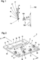
- Fig. 4 shows a cross-sectional view through an exterior aircraft light 2 in accordance with another exemplary embodiment of the invention.
- the exterior aircraft light 2 of Fig. 4 is similar to the exterior aircraft light 2 of Fig. 3 , and the viewing direction and cross-sectional plane of Fig. 4 are identical to Fig. 3 .
- Like elements are referred to with like reference numerals, and a description thereof is omitted for brevity.
- the exterior aircraft light 2 of Fig. 4 is identical to the exterior aircraft light 2 of Fig. 3 , with the exception that a parylene coating 20 is provided.
- the parylene coating is coated onto the entire mounting board enclosure and lens structure 8, i.e. it covers the entire outer surface of the mounting board enclosure and lens structure 8.
- the parylene coating 20 serves two purposes. First, the parylene coating is gas impermeable and protects the mounting board enclosure and lens structure 8 in the highly adverse operating conditions of exterior aircraft lights, in particular from corrosive gases. In particular, when an exterior aircraft light is placed close to a turbine exhaust, the parylene coating is an effective means of blocking the aggressive exhaust gases from the mounting board enclosure and lens structure 8.
- the parylene coating 20 forms a fairly rigid structure, thus forming a corset or case around the mounting board enclosure and lens structure 8.
- the mounting board 4 and the parylene coating 20 jointly provide enhanced stability to the mounting board enclosure and lens structure 8.
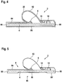
- Fig. 5 shows a cross-sectional view through an exterior aircraft light 2 in accordance with yet another exemplary embodiment of the invention.
- the exterior aircraft light 2 of Fig. 5 is similar to the exterior aircraft light 2 of Fig. 3 , and the viewing direction and cross-sectional plane of Fig. 5 are identical to Fig. 3 .
- Like elements are referred to with like reference numerals, and a description thereof is omitted for brevity.
- the exterior aircraft light 2 of Fig. 5 is identical to the exterior aircraft light 2 of Fig. 3 , with the exception that the mounting board enclosure and lens structure 8 is a composite structure of two materials that jointly enclose the mounting board 4 and the LED 6.
- the mounting board enclosure and lens structure 8 of Fig. 5 has two different materials that jointly cover the lower side of the mounting board 4.
- the lens 82, the top portion 84 of the covering layer, the side portions 88 of the covering layer, and an outer portion 86' of the bottom portion 86 of the covering layer are made from a one-piece soft silicone structure, as described above.
- An inner portion 90 of the bottom portion 86 of the covering layer is made from a filler material.
- the filler material 90 fills the silicone gap in the mounting board enclosure and lens structure 8, such that the mounting board enclosure and lens structure 8 as a whole fully encloses the mounting board 4, the LED 6 and the additional circuit components 10.
- a part of the silicone structure and the filler material 90 jointly form the bottom portion 86 of the covering layer of the mounting board enclosure and lens structure 8. In this way, there is also no edge of the silicone structure, such that the risk of the silicone structure peeling off inadvertently is kept low.
- the filler material 90 is parylene in the exemplary embodiment of Fig. 5 .
- the thickness of the filler material 90 is less than the thickness of the outer portion 86' of the silicone structure arranged on the lower side of the mounting board 4.
- the thicknesses are substantially the same, such that the mounting board 4 can be placed onto a housing of the exterior aircraft light 2 or the like with an even surface.
- Figs. 4 and 5 are combined, i.e. that the silicone structure has the shape shown in Fig. 5 and that a parylene coating fully encloses the silicone structure and the mounting board 4, thus filling the gap in the silicone structure at the lower side of the mounting board 4 and coating the entire silicone structure.
- the partitioning of the covering layer between the silicone structure and the filler material i.e. the splitting up of mounting board area between the silicone structure and the filler material, may be different. It is for example possible that only the portion of the mounting board enclosure and lens structure 8 on top of the upper side of the mounting board 4 is from silicone.
- the filler material then has an adapted extension that still ensures a full enclosure of the mounting board 4 by the combination of the silicone structure and the filler material.
Landscapes
- Engineering & Computer Science (AREA)
- General Engineering & Computer Science (AREA)
- Aviation & Aerospace Engineering (AREA)
- Led Device Packages (AREA)
- Non-Portable Lighting Devices Or Systems Thereof (AREA)
Applications Claiming Priority (1)
| Application Number | Priority Date | Filing Date | Title |
|---|---|---|---|
| DE102016102471 | 2016-02-12 |
Publications (2)
| Publication Number | Publication Date |
|---|---|
| EP3205584A1 true EP3205584A1 (de) | 2017-08-16 |
| EP3205584B1 EP3205584B1 (de) | 2020-06-03 |
Family
ID=57984790
Family Applications (1)
| Application Number | Title | Priority Date | Filing Date |
|---|---|---|---|
| EP17153937.2A Active EP3205584B1 (de) | 2016-02-12 | 2017-01-31 | Äussere flugzeugbeleuchtung und flugzeug damit |
Country Status (2)
| Country | Link |
|---|---|
| US (1) | US10343793B2 (de) |
| EP (1) | EP3205584B1 (de) |
Cited By (4)
| Publication number | Priority date | Publication date | Assignee | Title |
|---|---|---|---|---|
| FR3120931A1 (fr) * | 2021-03-16 | 2022-09-23 | Safran Electronics & Defense Cockpit Solutions | Dispositif optique pour feux de navigation avant d’aéronef |
| EP4403473A1 (de) * | 2023-01-17 | 2024-07-24 | Goodrich Lighting Systems GmbH & Co. KG | Flugzeugscheinwerfer, flugzeug mit einem flugzeugscheinwerfer und verfahren zur herstellung eines flugzeugscheinwerfers |
| US12312098B2 (en) | 2022-12-21 | 2025-05-27 | Goodrich Lighting Systems GmbH & Co. KG | Exterior aircraft light, aircraft comprising an exterior aircraft light, and method of assembling an exterior aircraft light |
| US12449116B2 (en) | 2023-08-01 | 2025-10-21 | Goodrich Lighting Systems GmbH & Co. KG | Aircraft light, aircraft comprising an aircraft light, method of assembling an aircraft light, and method of manufacturing a sensor cap for an aircraft light |
Families Citing this family (11)
| Publication number | Priority date | Publication date | Assignee | Title |
|---|---|---|---|---|
| ES2964029T3 (es) * | 2017-10-23 | 2024-04-03 | Goodrich Lighting Systems Gmbh | Unidad de luz exterior de aeronave y aeronave que comprende la misma |
| EP3527498B1 (de) * | 2018-02-16 | 2021-09-08 | Goodrich Lighting Systems GmbH | Flugzeugseitenleitwerkbeleuchtungslicht und damit ausgerüstetes flugzeug |
| EP3543145B1 (de) * | 2018-03-23 | 2021-08-18 | Goodrich Lighting Systems GmbH | Flugzeugaussenleuchte, flugzeug mit solch einer leuchte und verfahren zum betrieb einer flugzeugaussenleuchte |
| EP3584170B1 (de) | 2018-06-19 | 2021-08-11 | Goodrich Lighting Systems GmbH | Abdeckung für ein äusseres flugzeuglicht, äusseres flugzeuglicht und verfahren zur bestimmung eines verschleisszustands einer linsenabdeckungsstruktur |
| EP3584171B1 (de) | 2018-06-19 | 2023-07-26 | Goodrich Lighting Systems GmbH | Flugzeugbakenleuchte und flugzeug mit einer flugzeugbakenleuchte |
| WO2020121972A1 (ja) * | 2018-12-13 | 2020-06-18 | 株式会社小糸製作所 | 移動体用灯具、灯具システムおよび移動体用提示システム |
| US10882638B2 (en) * | 2019-04-16 | 2021-01-05 | Honeywell International Inc. | Systems and methods for aircraft adaptive ground safety lighting using edge nodes |
| EP3825234B1 (de) * | 2019-11-21 | 2023-06-07 | Goodrich Lighting Systems GmbH & Co. KG | Austauschbarer flugzeugaussenlichtkopf und verfahren zur bewertung eines betriebsstatus |
| EP4124794B1 (de) | 2021-07-28 | 2025-10-29 | Goodrich Lighting Systems GmbH & Co. KG | Äussere flugzeugbeleuchtung und flugzeug damit |
| US12054285B2 (en) | 2021-10-14 | 2024-08-06 | Goodrich Corporation | Heat containment method for aircraft tail lighting |
| EP4406858A1 (de) | 2023-01-24 | 2024-07-31 | Goodrich Lighting Systems GmbH & Co. KG | Flugzeugleuchte, flugzeug mit einer flugzeugleuchte und verfahren zur herstellung einer flugzeugleuchte |
Citations (5)
| Publication number | Priority date | Publication date | Assignee | Title |
|---|---|---|---|---|
| GB2334376A (en) * | 1996-11-12 | 1999-08-18 | L F D Limited | LED lamp assembly |
| DE102008009808A1 (de) * | 2008-02-19 | 2009-08-27 | Lighting Innovation Group Ag | LED-Lichtleiste höherer Schutzart |
| DE102010010819A1 (de) * | 2010-03-10 | 2011-09-15 | Osram Opto Semiconductors Gmbh | Verfahren und Vorrichtung zur Herstellung einer Parylen-Beschichtung |
| US20120195056A1 (en) * | 2011-01-27 | 2012-08-02 | Airbus Operations Limited | Aircraft lighting device |
| US20130176735A1 (en) * | 2010-09-21 | 2013-07-11 | Shinobu Kobayashi | Lighting apparatus |
Family Cites Families (23)
| Publication number | Priority date | Publication date | Assignee | Title |
|---|---|---|---|---|
| US5559681A (en) * | 1994-05-13 | 1996-09-24 | Cnc Automation, Inc. | Flexible, self-adhesive, modular lighting system |
| US6113248A (en) * | 1997-10-20 | 2000-09-05 | The Standard Products Company | Automated system for manufacturing an LED light strip having an integrally formed connector |
| DE10133255A1 (de) * | 2001-07-09 | 2003-01-30 | Osram Opto Semiconductors Gmbh | LED-Modul für Beleuchtungsvorrichtungen |
| US7018079B1 (en) * | 2001-07-23 | 2006-03-28 | Dme Corporation | Aircraft escape slide lighting system |
| US6871981B2 (en) * | 2001-09-13 | 2005-03-29 | Heads Up Technologies, Inc. | LED lighting device and system |
| TW558804B (en) * | 2002-04-16 | 2003-10-21 | Yuan Lin | Flexible light emitting device and the manufacturing method thereof |
| US7128442B2 (en) * | 2003-05-09 | 2006-10-31 | Kian Shin Lee | Illumination unit with a solid-state light generating source, a flexible substrate, and a flexible and optically transparent encapsulant |
| KR100757196B1 (ko) | 2005-08-01 | 2007-09-07 | 서울반도체 주식회사 | 실리콘 렌즈를 구비하는 발광소자 |
| KR20070045462A (ko) | 2005-10-27 | 2007-05-02 | 엘지이노텍 주식회사 | 발광 다이오드 패키지 |
| WO2009023602A1 (en) | 2007-08-10 | 2009-02-19 | Dialight Corporation | Silicone based circuit board indicator led lens |
| WO2009076579A2 (en) * | 2007-12-12 | 2009-06-18 | Innotec Corporation | Overmolded circuit board and method |
| CN101832518A (zh) | 2009-03-11 | 2010-09-15 | 旭明光电股份有限公司 | 具有复合萤光体层的发光二极管的发光装置 |
| US8697458B2 (en) | 2009-04-22 | 2014-04-15 | Shat-R-Shield, Inc. | Silicone coated light-emitting diode |
| US20110031516A1 (en) * | 2009-08-07 | 2011-02-10 | Koninklijke Philips Electronics N.V. | Led with silicone layer and laminated remote phosphor layer |
| US8414149B2 (en) | 2009-08-25 | 2013-04-09 | Daktronics, Inc. | Light element seal module and method for same |
| FI20105289A0 (fi) * | 2010-03-23 | 2010-03-23 | Marimils Oy | Valojohde ja sen valmistus |
| DE102011016935A1 (de) | 2011-04-13 | 2012-10-18 | Osram Opto Semiconductors Gmbh | Verfahren zur Herstellung eines Licht emittierenden Halbleiterbauelements und Licht emittierendes Halbleiterbauelement |
| US10686107B2 (en) * | 2011-07-21 | 2020-06-16 | Cree, Inc. | Light emitter devices and components with improved chemical resistance and related methods |
| KR102032392B1 (ko) | 2012-02-10 | 2019-10-16 | 루미리즈 홀딩 비.브이. | 칩 스케일 led 패키지를 형성하는 몰딩 렌즈 및 그의 제조 방법 |
| US8933473B1 (en) | 2012-06-01 | 2015-01-13 | Valery Dubin | Method, apparatus and system for providing light source structures on a flexible substrate |
| US9175840B2 (en) * | 2013-03-15 | 2015-11-03 | Evening Star Lighting Inc. | LED wall light fixture |
| US9464780B2 (en) * | 2013-03-15 | 2016-10-11 | General Led, Inc. | LED light engine for signage |
| CN203697831U (zh) | 2013-11-04 | 2014-07-09 | 宁波米德兰电子制造有限公司 | 一种新型圣诞老人像 |
-
2017
- 2017-01-31 EP EP17153937.2A patent/EP3205584B1/de active Active
- 2017-02-06 US US15/425,065 patent/US10343793B2/en active Active
Patent Citations (5)
| Publication number | Priority date | Publication date | Assignee | Title |
|---|---|---|---|---|
| GB2334376A (en) * | 1996-11-12 | 1999-08-18 | L F D Limited | LED lamp assembly |
| DE102008009808A1 (de) * | 2008-02-19 | 2009-08-27 | Lighting Innovation Group Ag | LED-Lichtleiste höherer Schutzart |
| DE102010010819A1 (de) * | 2010-03-10 | 2011-09-15 | Osram Opto Semiconductors Gmbh | Verfahren und Vorrichtung zur Herstellung einer Parylen-Beschichtung |
| US20130176735A1 (en) * | 2010-09-21 | 2013-07-11 | Shinobu Kobayashi | Lighting apparatus |
| US20120195056A1 (en) * | 2011-01-27 | 2012-08-02 | Airbus Operations Limited | Aircraft lighting device |
Cited By (5)
| Publication number | Priority date | Publication date | Assignee | Title |
|---|---|---|---|---|
| FR3120931A1 (fr) * | 2021-03-16 | 2022-09-23 | Safran Electronics & Defense Cockpit Solutions | Dispositif optique pour feux de navigation avant d’aéronef |
| US12312098B2 (en) | 2022-12-21 | 2025-05-27 | Goodrich Lighting Systems GmbH & Co. KG | Exterior aircraft light, aircraft comprising an exterior aircraft light, and method of assembling an exterior aircraft light |
| EP4403473A1 (de) * | 2023-01-17 | 2024-07-24 | Goodrich Lighting Systems GmbH & Co. KG | Flugzeugscheinwerfer, flugzeug mit einem flugzeugscheinwerfer und verfahren zur herstellung eines flugzeugscheinwerfers |
| US12352401B2 (en) | 2023-01-17 | 2025-07-08 | Goodrich Lighting Systems GmbH & Co. KG | Aircraft headlight, aircraft comprising an aircraft headlight and method of manufacturing an aircraft headlight |
| US12449116B2 (en) | 2023-08-01 | 2025-10-21 | Goodrich Lighting Systems GmbH & Co. KG | Aircraft light, aircraft comprising an aircraft light, method of assembling an aircraft light, and method of manufacturing a sensor cap for an aircraft light |
Also Published As
| Publication number | Publication date |
|---|---|
| US10343793B2 (en) | 2019-07-09 |
| EP3205584B1 (de) | 2020-06-03 |
| US20170233101A1 (en) | 2017-08-17 |
Similar Documents
| Publication | Publication Date | Title |
|---|---|---|
| US10343793B2 (en) | Silicone encapsulated aircraft LED light | |
| EP3476746B1 (de) | Flugzeugnavigationslicht und flugzeug damit | |
| US7794110B2 (en) | Anti-collision light for an aircraft | |
| US8337059B2 (en) | Control-surface-mounted landing and taxi lights | |
| CN102084567B (zh) | 电子单元的雷电防护装置 | |
| EP1510457A2 (de) | Antikollisionsleuchte für Luftfahrzeuge | |
| EP3670356B1 (de) | Kombiniertes vorwärtsnavigations- und kollisionsschutzlicht für ein flugzeug und flugzeug damit | |
| WO2005090157A1 (en) | Multi-platform led-based aircraft rear position light | |
| CN101896402A (zh) | 雷电保护系统以及包括该系统的飞行器 | |
| CN103328331B (zh) | 飞行器驾驶舱的顶面板和包括该面板的飞行器 | |
| EP2985228B1 (de) | Außenbeleuchtungseinheit für ein Flugzeug und Flugzeug damit | |
| US20160332746A1 (en) | Very low profile anti collision light | |
| US11794921B2 (en) | Aircraft lamp | |
| EP3254020B1 (de) | Led-modul und abdichtverfahren | |
| EP3668793B1 (de) | Flugfeldleuchte | |
| US11280472B2 (en) | Modular lighting system | |
| US20190016473A1 (en) | Lens structure for a light unit, light unit, and aircraft comprising such light unit | |
| EP1710845A1 (de) | Led und led-anbringstruktur | |
| EP4230530B1 (de) | Flugzeuglicht und flugzeug damit | |
| JP2013131551A (ja) | 基板ユニット | |
| US20080001557A1 (en) | Thermally conductive panel | |
| CN104515868B (zh) | 传感器单元、电子设备以及移动体 | |
| CN206118300U (zh) | 屏蔽装置及无人飞行器 | |
| US20250020308A1 (en) | Aircraft light, aircraft comprising an aircraft light and method of manufacturing an aircraft light | |
| GB2518825A (en) | A lighting unit |
Legal Events
| Date | Code | Title | Description |
|---|---|---|---|
| PUAI | Public reference made under article 153(3) epc to a published international application that has entered the european phase |
Free format text: ORIGINAL CODE: 0009012 |
|
| STAA | Information on the status of an ep patent application or granted ep patent |
Free format text: STATUS: THE APPLICATION HAS BEEN PUBLISHED |
|
| AK | Designated contracting states |
Kind code of ref document: A1 Designated state(s): AL AT BE BG CH CY CZ DE DK EE ES FI FR GB GR HR HU IE IS IT LI LT LU LV MC MK MT NL NO PL PT RO RS SE SI SK SM TR |
|
| AX | Request for extension of the european patent |
Extension state: BA ME |
|
| STAA | Information on the status of an ep patent application or granted ep patent |
Free format text: STATUS: REQUEST FOR EXAMINATION WAS MADE |
|
| 17P | Request for examination filed |
Effective date: 20180216 |
|
| RBV | Designated contracting states (corrected) |
Designated state(s): AL AT BE BG CH CY CZ DE DK EE ES FI FR GB GR HR HU IE IS IT LI LT LU LV MC MK MT NL NO PL PT RO RS SE SI SK SM TR |
|
| GRAP | Despatch of communication of intention to grant a patent |
Free format text: ORIGINAL CODE: EPIDOSNIGR1 |
|
| STAA | Information on the status of an ep patent application or granted ep patent |
Free format text: STATUS: GRANT OF PATENT IS INTENDED |
|
| RIC1 | Information provided on ipc code assigned before grant |
Ipc: B64D 47/04 20060101AFI20191127BHEP Ipc: B64D 47/06 20060101ALI20191127BHEP |
|
| INTG | Intention to grant announced |
Effective date: 20191213 |
|
| GRAS | Grant fee paid |
Free format text: ORIGINAL CODE: EPIDOSNIGR3 |
|
| GRAA | (expected) grant |
Free format text: ORIGINAL CODE: 0009210 |
|
| STAA | Information on the status of an ep patent application or granted ep patent |
Free format text: STATUS: THE PATENT HAS BEEN GRANTED |
|
| AK | Designated contracting states |
Kind code of ref document: B1 Designated state(s): AL AT BE BG CH CY CZ DE DK EE ES FI FR GB GR HR HU IE IS IT LI LT LU LV MC MK MT NL NO PL PT RO RS SE SI SK SM TR |
|
| REG | Reference to a national code |
Ref country code: GB Ref legal event code: FG4D |
|
| REG | Reference to a national code |
Ref country code: AT Ref legal event code: REF Ref document number: 1276777 Country of ref document: AT Kind code of ref document: T Effective date: 20200615 Ref country code: CH Ref legal event code: EP |
|
| REG | Reference to a national code |
Ref country code: DE Ref legal event code: R096 Ref document number: 602017017504 Country of ref document: DE |
|
| REG | Reference to a national code |
Ref country code: LT Ref legal event code: MG4D |
|
| PG25 | Lapsed in a contracting state [announced via postgrant information from national office to epo] |
Ref country code: FI Free format text: LAPSE BECAUSE OF FAILURE TO SUBMIT A TRANSLATION OF THE DESCRIPTION OR TO PAY THE FEE WITHIN THE PRESCRIBED TIME-LIMIT Effective date: 20200603 Ref country code: SE Free format text: LAPSE BECAUSE OF FAILURE TO SUBMIT A TRANSLATION OF THE DESCRIPTION OR TO PAY THE FEE WITHIN THE PRESCRIBED TIME-LIMIT Effective date: 20200603 Ref country code: LT Free format text: LAPSE BECAUSE OF FAILURE TO SUBMIT A TRANSLATION OF THE DESCRIPTION OR TO PAY THE FEE WITHIN THE PRESCRIBED TIME-LIMIT Effective date: 20200603 Ref country code: GR Free format text: LAPSE BECAUSE OF FAILURE TO SUBMIT A TRANSLATION OF THE DESCRIPTION OR TO PAY THE FEE WITHIN THE PRESCRIBED TIME-LIMIT Effective date: 20200904 Ref country code: NO Free format text: LAPSE BECAUSE OF FAILURE TO SUBMIT A TRANSLATION OF THE DESCRIPTION OR TO PAY THE FEE WITHIN THE PRESCRIBED TIME-LIMIT Effective date: 20200903 |
|
| REG | Reference to a national code |
Ref country code: NL Ref legal event code: MP Effective date: 20200603 |
|
| PG25 | Lapsed in a contracting state [announced via postgrant information from national office to epo] |
Ref country code: BG Free format text: LAPSE BECAUSE OF FAILURE TO SUBMIT A TRANSLATION OF THE DESCRIPTION OR TO PAY THE FEE WITHIN THE PRESCRIBED TIME-LIMIT Effective date: 20200903 Ref country code: RS Free format text: LAPSE BECAUSE OF FAILURE TO SUBMIT A TRANSLATION OF THE DESCRIPTION OR TO PAY THE FEE WITHIN THE PRESCRIBED TIME-LIMIT Effective date: 20200603 Ref country code: LV Free format text: LAPSE BECAUSE OF FAILURE TO SUBMIT A TRANSLATION OF THE DESCRIPTION OR TO PAY THE FEE WITHIN THE PRESCRIBED TIME-LIMIT Effective date: 20200603 Ref country code: HR Free format text: LAPSE BECAUSE OF FAILURE TO SUBMIT A TRANSLATION OF THE DESCRIPTION OR TO PAY THE FEE WITHIN THE PRESCRIBED TIME-LIMIT Effective date: 20200603 |
|
| REG | Reference to a national code |
Ref country code: AT Ref legal event code: MK05 Ref document number: 1276777 Country of ref document: AT Kind code of ref document: T Effective date: 20200603 |
|
| PG25 | Lapsed in a contracting state [announced via postgrant information from national office to epo] |
Ref country code: NL Free format text: LAPSE BECAUSE OF FAILURE TO SUBMIT A TRANSLATION OF THE DESCRIPTION OR TO PAY THE FEE WITHIN THE PRESCRIBED TIME-LIMIT Effective date: 20200603 Ref country code: AL Free format text: LAPSE BECAUSE OF FAILURE TO SUBMIT A TRANSLATION OF THE DESCRIPTION OR TO PAY THE FEE WITHIN THE PRESCRIBED TIME-LIMIT Effective date: 20200603 |
|
| PG25 | Lapsed in a contracting state [announced via postgrant information from national office to epo] |
Ref country code: SM Free format text: LAPSE BECAUSE OF FAILURE TO SUBMIT A TRANSLATION OF THE DESCRIPTION OR TO PAY THE FEE WITHIN THE PRESCRIBED TIME-LIMIT Effective date: 20200603 Ref country code: IT Free format text: LAPSE BECAUSE OF FAILURE TO SUBMIT A TRANSLATION OF THE DESCRIPTION OR TO PAY THE FEE WITHIN THE PRESCRIBED TIME-LIMIT Effective date: 20200603 Ref country code: EE Free format text: LAPSE BECAUSE OF FAILURE TO SUBMIT A TRANSLATION OF THE DESCRIPTION OR TO PAY THE FEE WITHIN THE PRESCRIBED TIME-LIMIT Effective date: 20200603 Ref country code: CZ Free format text: LAPSE BECAUSE OF FAILURE TO SUBMIT A TRANSLATION OF THE DESCRIPTION OR TO PAY THE FEE WITHIN THE PRESCRIBED TIME-LIMIT Effective date: 20200603 Ref country code: PT Free format text: LAPSE BECAUSE OF FAILURE TO SUBMIT A TRANSLATION OF THE DESCRIPTION OR TO PAY THE FEE WITHIN THE PRESCRIBED TIME-LIMIT Effective date: 20201006 Ref country code: RO Free format text: LAPSE BECAUSE OF FAILURE TO SUBMIT A TRANSLATION OF THE DESCRIPTION OR TO PAY THE FEE WITHIN THE PRESCRIBED TIME-LIMIT Effective date: 20200603 Ref country code: ES Free format text: LAPSE BECAUSE OF FAILURE TO SUBMIT A TRANSLATION OF THE DESCRIPTION OR TO PAY THE FEE WITHIN THE PRESCRIBED TIME-LIMIT Effective date: 20200603 Ref country code: AT Free format text: LAPSE BECAUSE OF FAILURE TO SUBMIT A TRANSLATION OF THE DESCRIPTION OR TO PAY THE FEE WITHIN THE PRESCRIBED TIME-LIMIT Effective date: 20200603 |
|
| PG25 | Lapsed in a contracting state [announced via postgrant information from national office to epo] |
Ref country code: IS Free format text: LAPSE BECAUSE OF FAILURE TO SUBMIT A TRANSLATION OF THE DESCRIPTION OR TO PAY THE FEE WITHIN THE PRESCRIBED TIME-LIMIT Effective date: 20201003 Ref country code: PL Free format text: LAPSE BECAUSE OF FAILURE TO SUBMIT A TRANSLATION OF THE DESCRIPTION OR TO PAY THE FEE WITHIN THE PRESCRIBED TIME-LIMIT Effective date: 20200603 Ref country code: SK Free format text: LAPSE BECAUSE OF FAILURE TO SUBMIT A TRANSLATION OF THE DESCRIPTION OR TO PAY THE FEE WITHIN THE PRESCRIBED TIME-LIMIT Effective date: 20200603 |
|
| REG | Reference to a national code |
Ref country code: DE Ref legal event code: R097 Ref document number: 602017017504 Country of ref document: DE |
|
| PLBE | No opposition filed within time limit |
Free format text: ORIGINAL CODE: 0009261 |
|
| STAA | Information on the status of an ep patent application or granted ep patent |
Free format text: STATUS: NO OPPOSITION FILED WITHIN TIME LIMIT |
|
| PG25 | Lapsed in a contracting state [announced via postgrant information from national office to epo] |
Ref country code: DK Free format text: LAPSE BECAUSE OF FAILURE TO SUBMIT A TRANSLATION OF THE DESCRIPTION OR TO PAY THE FEE WITHIN THE PRESCRIBED TIME-LIMIT Effective date: 20200603 |
|
| 26N | No opposition filed |
Effective date: 20210304 |
|
| PG25 | Lapsed in a contracting state [announced via postgrant information from national office to epo] |
Ref country code: SI Free format text: LAPSE BECAUSE OF FAILURE TO SUBMIT A TRANSLATION OF THE DESCRIPTION OR TO PAY THE FEE WITHIN THE PRESCRIBED TIME-LIMIT Effective date: 20200603 |
|
| PG25 | Lapsed in a contracting state [announced via postgrant information from national office to epo] |
Ref country code: MC Free format text: LAPSE BECAUSE OF FAILURE TO SUBMIT A TRANSLATION OF THE DESCRIPTION OR TO PAY THE FEE WITHIN THE PRESCRIBED TIME-LIMIT Effective date: 20200603 |
|
| REG | Reference to a national code |
Ref country code: CH Ref legal event code: PL |
|
| PG25 | Lapsed in a contracting state [announced via postgrant information from national office to epo] |
Ref country code: LU Free format text: LAPSE BECAUSE OF NON-PAYMENT OF DUE FEES Effective date: 20210131 |
|
| REG | Reference to a national code |
Ref country code: BE Ref legal event code: MM Effective date: 20210131 |
|
| PG25 | Lapsed in a contracting state [announced via postgrant information from national office to epo] |
Ref country code: CH Free format text: LAPSE BECAUSE OF NON-PAYMENT OF DUE FEES Effective date: 20210131 Ref country code: LI Free format text: LAPSE BECAUSE OF NON-PAYMENT OF DUE FEES Effective date: 20210131 |
|
| PG25 | Lapsed in a contracting state [announced via postgrant information from national office to epo] |
Ref country code: IE Free format text: LAPSE BECAUSE OF NON-PAYMENT OF DUE FEES Effective date: 20210131 |
|
| PG25 | Lapsed in a contracting state [announced via postgrant information from national office to epo] |
Ref country code: BE Free format text: LAPSE BECAUSE OF NON-PAYMENT OF DUE FEES Effective date: 20210131 |
|
| PG25 | Lapsed in a contracting state [announced via postgrant information from national office to epo] |
Ref country code: HU Free format text: LAPSE BECAUSE OF FAILURE TO SUBMIT A TRANSLATION OF THE DESCRIPTION OR TO PAY THE FEE WITHIN THE PRESCRIBED TIME-LIMIT; INVALID AB INITIO Effective date: 20170131 |
|
| PG25 | Lapsed in a contracting state [announced via postgrant information from national office to epo] |
Ref country code: CY Free format text: LAPSE BECAUSE OF FAILURE TO SUBMIT A TRANSLATION OF THE DESCRIPTION OR TO PAY THE FEE WITHIN THE PRESCRIBED TIME-LIMIT Effective date: 20200603 |
|
| P01 | Opt-out of the competence of the unified patent court (upc) registered |
Effective date: 20230630 |
|
| PG25 | Lapsed in a contracting state [announced via postgrant information from national office to epo] |
Ref country code: MK Free format text: LAPSE BECAUSE OF FAILURE TO SUBMIT A TRANSLATION OF THE DESCRIPTION OR TO PAY THE FEE WITHIN THE PRESCRIBED TIME-LIMIT Effective date: 20200603 |
|
| PG25 | Lapsed in a contracting state [announced via postgrant information from national office to epo] |
Ref country code: MT Free format text: LAPSE BECAUSE OF FAILURE TO SUBMIT A TRANSLATION OF THE DESCRIPTION OR TO PAY THE FEE WITHIN THE PRESCRIBED TIME-LIMIT Effective date: 20200603 |
|
| PGFP | Annual fee paid to national office [announced via postgrant information from national office to epo] |
Ref country code: DE Payment date: 20241218 Year of fee payment: 9 |
|
| PG25 | Lapsed in a contracting state [announced via postgrant information from national office to epo] |
Ref country code: TR Free format text: LAPSE BECAUSE OF FAILURE TO SUBMIT A TRANSLATION OF THE DESCRIPTION OR TO PAY THE FEE WITHIN THE PRESCRIBED TIME-LIMIT Effective date: 20200603 |
|
| PGFP | Annual fee paid to national office [announced via postgrant information from national office to epo] |
Ref country code: GB Payment date: 20251220 Year of fee payment: 10 |
|
| PGFP | Annual fee paid to national office [announced via postgrant information from national office to epo] |
Ref country code: FR Payment date: 20251217 Year of fee payment: 10 |