EP2985228B1 - Außenbeleuchtungseinheit für ein Flugzeug und Flugzeug damit - Google Patents
Außenbeleuchtungseinheit für ein Flugzeug und Flugzeug damit Download PDFInfo
- Publication number
- EP2985228B1 EP2985228B1 EP14180962.4A EP14180962A EP2985228B1 EP 2985228 B1 EP2985228 B1 EP 2985228B1 EP 14180962 A EP14180962 A EP 14180962A EP 2985228 B1 EP2985228 B1 EP 2985228B1
- Authority
- EP
- European Patent Office
- Prior art keywords
- light
- lens cover
- light sources
- light unit
- exterior aircraft
- Prior art date
- Legal status (The legal status is an assumption and is not a legal conclusion. Google has not performed a legal analysis and makes no representation as to the accuracy of the status listed.)
- Active
Links
- 230000003287 optical effect Effects 0.000 claims description 52
- 238000009826 distribution Methods 0.000 description 23
- 230000000694 effects Effects 0.000 description 9
- 238000007493 shaping process Methods 0.000 description 6
- 230000008901 benefit Effects 0.000 description 5
- 230000009286 beneficial effect Effects 0.000 description 4
- 230000002349 favourable effect Effects 0.000 description 4
- 230000033228 biological regulation Effects 0.000 description 3
- 230000009467 reduction Effects 0.000 description 3
- 239000007787 solid Substances 0.000 description 3
- 230000009466 transformation Effects 0.000 description 3
- 238000013459 approach Methods 0.000 description 2
- 230000008859 change Effects 0.000 description 2
- 238000005516 engineering process Methods 0.000 description 2
- 238000005286 illumination Methods 0.000 description 2
- 239000000463 material Substances 0.000 description 2
- 238000012986 modification Methods 0.000 description 2
- 230000004048 modification Effects 0.000 description 2
- 210000001015 abdomen Anatomy 0.000 description 1
- 230000009471 action Effects 0.000 description 1
- 230000002411 adverse Effects 0.000 description 1
- 230000000903 blocking effect Effects 0.000 description 1
- 238000012512 characterization method Methods 0.000 description 1
- 239000003086 colorant Substances 0.000 description 1
- 239000012141 concentrate Substances 0.000 description 1
- 230000001419 dependent effect Effects 0.000 description 1
- 238000009792 diffusion process Methods 0.000 description 1
- 230000008030 elimination Effects 0.000 description 1
- 238000003379 elimination reaction Methods 0.000 description 1
- 230000020169 heat generation Effects 0.000 description 1
- 230000010354 integration Effects 0.000 description 1
- 238000000034 method Methods 0.000 description 1
- 230000011664 signaling Effects 0.000 description 1
- 230000001131 transforming effect Effects 0.000 description 1
Images


Classifications
-
- B—PERFORMING OPERATIONS; TRANSPORTING
- B64—AIRCRAFT; AVIATION; COSMONAUTICS
- B64D—EQUIPMENT FOR FITTING IN OR TO AIRCRAFT; FLIGHT SUITS; PARACHUTES; ARRANGEMENT OR MOUNTING OF POWER PLANTS OR PROPULSION TRANSMISSIONS IN AIRCRAFT
- B64D47/00—Equipment not otherwise provided for
- B64D47/02—Arrangements or adaptations of signal or lighting devices
- B64D47/06—Arrangements or adaptations of signal or lighting devices for indicating aircraft presence
-
- F—MECHANICAL ENGINEERING; LIGHTING; HEATING; WEAPONS; BLASTING
- F21—LIGHTING
- F21V—FUNCTIONAL FEATURES OR DETAILS OF LIGHTING DEVICES OR SYSTEMS THEREOF; STRUCTURAL COMBINATIONS OF LIGHTING DEVICES WITH OTHER ARTICLES, NOT OTHERWISE PROVIDED FOR
- F21V5/00—Refractors for light sources
- F21V5/04—Refractors for light sources of lens shape
- F21V5/048—Refractors for light sources of lens shape the lens being a simple lens adapted to cooperate with a point-like source for emitting mainly in one direction and having an axis coincident with the main light transmission direction, e.g. convergent or divergent lenses, plano-concave or plano-convex lenses
-
- B—PERFORMING OPERATIONS; TRANSPORTING
- B64—AIRCRAFT; AVIATION; COSMONAUTICS
- B64D—EQUIPMENT FOR FITTING IN OR TO AIRCRAFT; FLIGHT SUITS; PARACHUTES; ARRANGEMENT OR MOUNTING OF POWER PLANTS OR PROPULSION TRANSMISSIONS IN AIRCRAFT
- B64D2203/00—Aircraft or airfield lights using LEDs
-
- F—MECHANICAL ENGINEERING; LIGHTING; HEATING; WEAPONS; BLASTING
- F21—LIGHTING
- F21W—INDEXING SCHEME ASSOCIATED WITH SUBCLASSES F21K, F21L, F21S and F21V, RELATING TO USES OR APPLICATIONS OF LIGHTING DEVICES OR SYSTEMS
- F21W2107/00—Use or application of lighting devices on or in particular types of vehicles
- F21W2107/30—Use or application of lighting devices on or in particular types of vehicles for aircraft
-
- F—MECHANICAL ENGINEERING; LIGHTING; HEATING; WEAPONS; BLASTING
- F21—LIGHTING
- F21Y—INDEXING SCHEME ASSOCIATED WITH SUBCLASSES F21K, F21L, F21S and F21V, RELATING TO THE FORM OR THE KIND OF THE LIGHT SOURCES OR OF THE COLOUR OF THE LIGHT EMITTED
- F21Y2115/00—Light-generating elements of semiconductor light sources
- F21Y2115/10—Light-emitting diodes [LED]
Definitions
- the present invention relates to exterior aircraft lighting.
- it relates to exterior aircraft light units that are arranged in space-critical parts of an aircraft, such as wing tip locations.
- Exterior lights are used for a variety of purposes. Some aircraft lights allow the pilots and crew to have a better active visibility of the aircraft itself and of the environment. Other lights are used for passive visibility of the aircraft or for signalling purposes. Examples of such lights are navigation lights, beacon lights or anti-collision lights.
- Document EP 1 731 423 A1 describes an exterior aircraft light unit, comprising a mounting structure and a plurality of first light sources arranged on the mounting structure.
- a lens cover is arranged over the plurality of first light sources.
- the lens cover has a convex shape in a first cross-sectional plane.
- the plurality of first light sources are arranged in a circle within the circular cross-section of the lens cover.
- the lighting arrangement includes a navigational lighting group disposed at a leading edge of a wing.
- Document US 2010/0027281 A1 discloses an anti-collision light for commercial aircraft.
- the light includes a plurality of round circuit boards with an annular ring of surface mounted LEDs, with a disk having an edge configured as an offset half parabolic reflector.
- Document WO 2009/084049 A1 describes an anti-collision light for aircraft comprising two illuminating modules. Each module comprises a number of LEDs disposed along a ring and coplanar to a plane, a first reflector facing the LEDS and a second reflector surrounding the LEDS.
- Document US 6,191,541 B1 discloses a vehicle light and method for use in applications experiencing vibrational loading and wide temperature variations.
- the light includes a solid state illumination device (LED cluster) and an enclosure covering the solid state illumination device.
- LED cluster solid state illumination device
- the warning signal light bar includes an LED light source assembly.
- a plurality of light directors are positioned proximate to the LED light sources which in conjunction with the cover function to direct and focus the light emitted from the LED's in a desired direction or area.
- Document EP 2 023 038 A2 discloses a LED diffusion lens for LCD backlighting.
- URL http://www.planeandpilotmag.com/article/the-new-2014-generation-5-cirrus-aircraft/#.WM_b4nrdfSg, published October 28, 2013 describes an exterior light in a wing tip of an aircraft.
- the light sources employ LED lighting technology.
- a light source cover with a convex shape is provided. Accordingly, it would be beneficial to provide an exterior aircraft light unit that is able to satisfy predefined or desired light emission requirements without posing too much of a burden in terms of required space.
- Exemplary embodiments of the invention include an exterior aircraft light unit, as claimed in claim 1. Further exemplary embodiments are disclosed in the dependent claims.
- An exemplary embodiment of the invention includes an exterior aircraft light unit, comprising a mounting structure, a plurality of first light sources arranged on the mounting structure, and a lens cover arranged over the plurality of first light sources, the lens cover having a convex shape at least in a first cross-sectional plane.
- the plurality of first light sources are arranged in a curved pattern, with the curved pattern having the same direction of curvature as the convex shape of the lens cover in the first cross-sectional plane.
- the combination of the curved pattern of the first light sources and the convex shape of the lens cover allows for a very space-efficient design of the exterior aircraft light unit and allows for very favourable conditions in terms of using the light emitted by the first light sources for satisfying desired/required light intensity distributions.
- the convex shape of the lens cover and the curved pattern of the first light sources allow for the overall dimensions of the exterior aircraft light unit to be small, as compared to prior art approaches.
- the convex shape of the lens cover allows for the exterior aircraft light unit to be integrated into aerodynamic structures of the aircraft that have a relatively small curvature radius, such as the wing tips of an airplane.
- the convex shape of the lens cover may be readily integrated into and contribute to the aerodynamic structure in question.
- the influence of the lens cover on the light intensity distribution emitted from the exterior aircraft light unit is kept low.
- the amount of internal reflection at the lens cover can be kept small. Such internal reflection not only adversely effects the overall light yield of the exterior aircraft light unit. It may also lead to entirely undesired effects, such as a further reflection at some structure within the exterior aircraft light unit and an ensuing leaving of the lens cover in an entirely undesired direction, such as towards the cockpit windows.
- the combination of the curved pattern of the first light sources and the convex shape of the lens cover may lead to a significantly reduced size of the aircraft light unit, to a better integration into aerodynamic structures, and to an increased efficiency.
- the reduced size may also lead to a lower weight of the exterior aircraft light unit.
- the higher efficiency may also lead to lower electrical power consumption, which in turn leads to lower heat generation, better thermal management and higher reliability.
- the exterior aircraft light unit may only need a small opening to be inserted. This eliminates the need for big cut-outs in the wing structure, as were common for the big and expensive cover lenses of the prior art.
- convex shape refers to the direction of curvature, when seen from outside of the exterior aircraft light unit. Accordingly, the lens cover has a convex shape when seen from the outside in an installed condition. Conversely, when seen from the plurality of first light sources, the lens cover has a concave shape.
- the expression same direction of curvature refers to the same characterization in terms of being convex or concave. Accordingly, when the exterior aircraft light unit is installed and when the lens cover is removed, the curved pattern of the first light sources is a convexly curved pattern when viewed at from the outside.
- the expression arranged in a curved pattern refers to an arrangement where the mounting bases of the light sources are angled with respect to each other in such a way that the normal light emission directions of the first light sources are angled with respect to each other.
- the expression curved pattern refers to an angled arrangement of the normal light emission directions of the first light sources.
- the plurality of first light sources are oriented towards the convex shape lens cover in the first cross-sectional plane.
- lens cover refers to the outermost portion of the exterior aircraft light unit, through which the light is emitted.
- the lens cover is a generally transparent structure that allows for the light from the first light sources to travel therethrough.
- the lens cover may be fully transparent and permit all colours of light therethrough. It is also possible that the lens cover is a colour filter and ensures the output of certain wavelengths only.
- the plurality of first light sources are arranged as a row of adjacent light sources in the curved pattern.
- the first light sources form a single file of light sources along the curved pattern.
- the first light sources may be placed in similar positions with respect to the convex shape lens cover. This allows for a particularly manageable shaping of the joint light emission distribution of the plurality of first light sources.
- the first light sources all benefit from the arrangement in the curved pattern in a similar.
- a curvature radius of the lens cover is between 100% and 200%, in particular between 100% and 140%, of a curvature radius of the curved pattern along at least 80% of the curved pattern in the first cross-sectional plane.
- the light emitted from the plurality of first light sources towards the lens cover at an angle that is not normal to the lens cover will be affected less by the refractive action of the lens cover, the more the curvature radius of the lens cover and the curvature radius of the curved pattern correspond.
- the curved pattern and/or the convex shape are circular. However, this is not necessarily the case.
- the convex shape and/or the curved pattern may be at least partially non-circular in many applications. Accordingly, the curvature radius may change along the convex shape and/or along the curved pattern in the first cross-sectional plane. In other words, for every point along the curved pattern and along the convex shape, a specific curvature radius can be determined.
- the comparison between the curvature radius of the curved pattern and the curvature radius of the convex shape takes place in such a way that the curvature radius at a specific point of the curved pattern is compared to the curvature radius of a point of the convex shape that is reached by a straight line leaving the curved pattern in a direction normal thereto.
- a curvature radius of the curved pattern may be between 50% and 100%, in particular between 70% and 100%, of a curvature radius of the lens cover in the first cross-sectional plane along at least 80% of the curved pattern. While these threshold values do not entirely correspond to the threshold values given above, analogous benefits may be achieved.
- the curved pattern and the lens cover have such corresponding shapes that light emitted from the plurality of first light sources in a direction normal to the curved pattern reaches the lens cover at an angle of less than 45°, in particular of less than 30°, with respect to a direction normal to the lens cover.
- the curvature radius of the curved pattern and the curvature radius of the lens cover greatly deviate from each other, it can be ensured that at least the light emitted from the plurality of first light sources in a normal direction, which generally is the strongest light emission direction, reaches the lens cover at a favourable angle.
- these corresponding shapes leading to favourable angles are particularly beneficial in the case of the curvature radius of the curved pattern and the curvature radius of the lens cover corresponding to a great extent, as discussed above.
- the lens cover has a convex shape in a plurality of second cross-sectional planes orthogonal to the first cross-sectional plane and extending through the plurality of first light sources.
- each of the second cross-sectional planes may be defined with respect to one of the plurality of first light sources.
- the second cross-sectional plane in question may be orthogonal to the first cross-sectional plane, extend through the center of the respective first light source, and contain the light emission direction normal to to the curved pattern.
- the convex shape in the first cross-sectional plane may track the front edge curvature of an airplane wing, while the convex shape in the plurality of second cross-sectional planes may track the airfoil profile on the upper and/or lower surface of the wing of the airplane.
- the plurality of first light sources are spaced from the lens cover in such a way that the light, emitted from the plurality of first light sources in the plurality of second cross-sectional planes at an angle of less than 45° with respect to a direction normal to the curved pattern, reaches the lens cover at an angle of less than 30°, in particular of less than 20°, with respect to a direction normal to the lens cover.
- the convex curvature of the lens cover in the plurality of second cross-sectional planes is such that the lens cover wraps around the plurality of first light sources in the respective second cross-sectional planes.
- any undesired refractive effects of the lens cover in the plurality of second cross-sectional planes are reduced. Again, it is ensured that much of the light emitted by the plurality of first light sources reaches the lens cover at angles close to a normal angle. Again, this reduces undesired refractive effects and undesired internal reflection.
- a distance between the respective first light source and the lens cover is less than 200%, in particular between 50% and 150%, of a curvature radius of the lens cover in the respective second cross-sectional plane.
- the curvature radius of the lens cover in the respective second cross-sectional plane may change along the lens cover.
- the curvature radius of the lens cover in the respective second cross-sectional plane is defined to be the curvature radius of the lens cover in the respective second cross-sectional plane in the normal emission direction of the respective first light source.
- a refractive optical element is arranged between the plurality of first light sources and the lens cover.
- a desired light emission distribution may be shaped on the inside of the lens cover, before the light from the plurality of first light sources reaches the lens cover.
- multiple refractive optical elements are arranged between the plurality of first light sources and the lens cover, with each of the multiple refractive optical elements shaping the light emission distribution of one or more first light sources.
- Said refractive optical element(s) and the lens cover transform the light intensity distribution, as emitted by the plurality of the first light sources, into the output light emission distribution of the exterior aircraft light unit. It is possible to design the refractive optical element(s) in such a way that it/they provide(s) for the desired transformation by itself/themselves and to design the lens cover for minimum optical effects. It is also possible to split up the transformation between the refractive optical element(s) and the lens cover.
- the refractive optical element has a curved shape, extending along the curved pattern of the plurality of first light sources.
- the curved refractive optical element may effect the light emitted by the plurality of first light sources in an identical or similar manner for all of the first light sources.
- the refractive optical element comprises, in at least one second cross-sectional plane orthogonal to the first cross-sectional plane and extending through one of the plurality of first light sources, a combination of convex and concave outer surface portions.
- a combination of convex and concave outer surface portions allows for a particularly efficient way of transforming the light emission distribution into a desired light emission distribution in the second cross-sectional plane, in particular into a desired vertical light intensity distribution of an anti-collision light.
- the combination of convex and concave outer surface portions may be symmetrical with respect to the main light emission direction of the first light source, i.e. with respect to the emission direction normal to the mounting structure.
- a space between the plurality of first light sources and the lens cover is free of reflectors.
- the space may also be free of shutters.
- the exterior aircraft light unit as a whole may be configured to have no reflectors and/or no shutters. In this way, an optimized portion of the light emitted by the first light sources may be used for the desired/required output light intensity distribution.
- the exterior aircraft light unit is configured to be mounted to an aircraft with the first cross-sectional plane being oriented horizontally.
- the spread of the light emission distribution due to the curved pattern of the plurality of first light sources can be taken advantage of in a horizontal plane. This is particularly beneficial for light units with a comparably large opening angle in a horizontal direction, such as anti-collision lights.
- the exterior aircraft light unit is one of an anti-collision light unit and a beacon light unit.
- Both anti-collision lights and beacon lights are provided on most airplanes for avoiding collisions.
- Anti-collision lights are commonly flashing lights that may be installed in the wing tips and the tail of the an airplane in order to call a high degree of attention to the airplane.
- Anti-collision lights are mainly used during the flight.
- Beacon lights are often installed on the top and at the belly of the airplane fuselage. They often emit light in a revolving pattern, in particular attracting attention to the airplane on the ground when the engines are running. They are particularly helpful for ground personnel as a warning sign.
- the exterior aircraft light unit may emit light of a white and/or red colour.
- the exterior aircraft light unit is configured to be arranged in an aerodynamic structure of an airplane wing, in particular of an airplane wing tip.
- the exterior aircraft light unit further comprises at least one second light source arranged on the mounting structure and positioned besides the curved pattern of the plurality of first light sources.
- the exterior aircraft light unit may be adapted to integrate the functions of two exterior aircraft light units into one housing and underneath one lens cover. This again saves space and allows for a space-and power-efficient design of the overall aircraft lighting.
- each of the at least one second light source has a dedicated refractive optical element arranged between the respective second light source and the lens cover.
- These dedicated refractive optical elements allow for a desired transformation of the light emission distribution of the at least one second light source.
- the shaping of the light emission from the at least one second light source can be performed independently from the shaping of the light emission from the plurality of first light sources, leading to an overall highly accurate and space-efficient design.
- the plurality of first light sources, the refractive optical element, the at least one second light source, and the dedicated refractive optical element(s) may be arranged in such a way that no crossing between the light of the first light sources and the light of the at least one second light source takes place, before the light is refracted by the refractive optical element and the dedicated refractive optical element(s).
- the plurality of first light sources and the at least one second light source may be connected to one circuit board.
- all of the plurality of first light sources and the at least one second light source may be connected to the same circuit board. Accordingly, only one circuit board may be needed for providing the functionality of two different light units.
- the circuit board may be a printed circuit board or any other kind of circuit board, to which the light sources may be attached for their electrical connections.
- the exterior aircraft light unit is one of a combined anti-collision and navigation light unit and a combined beacon and navigation light unit, with the plurality of first light sources functioning as one of an anti-collision light and a beacon light and with the at least one second light source functioning as a navigation light.
- the term navigation light refers to the kind of exterior aircraft light units that constantly emit light for passive visibility. In many applications, a navigation light emits one of red, green and white light, such that other aircraft can deduce the orientation and moving direction of the aircraft in question.
- the combination of the curved pattern of first light sources and the convex shape of the lens cover allow for a very compact light unit design that is able to integrate the plurality of first light sources and the at least one second light source in a small space, without the light sources blocking each other's light output.
- the plurality of first light sources and/or the at least one second light source are/is LED(s).
- LEDs are/is LED(s).
- Providing LEDs as light sources allows for high light yield, high efficiency and low space requirements. Accordingly, above discussed features with respect to the arrangement of the light sources and the interdependence between this arrangement and the lens cover shape are particularly beneficial in the context of using LEDs as light sources.
- the LED's may be oriented with their axes substantially in the first cross-sectional plane. In other words, the LED's may have their light emission direction of highest intensity substantially in the first cross-sectional plane.
- Exemplary embodiments of the invention further include an aircraft, such as an airplane, comprising at least one exterior aircraft light unit, as described in any of the embodiments above.
- an aircraft such as an airplane
- the exterior aircraft light unit is applicable to the aircraft in an analogous manner.
- Fig. 1 shows an exemplary exterior aircraft light unit 2 in accordance with an exemplary embodiment of the present invention.
- the exterior aircraft light unit 2 is shown in a cross-sectional view in Fig. 1 .
- the cross-section is taken along a first cross-sectional plane, which first cross-section plane is a horizontal cross-sectional plane, when the exterior aircraft light unit 2 is arranged in its operating position.
- the exterior aircraft light unit 2 has a mounting structure 4.
- the mounting structure 4 has a main portion 40 and a leg portion 42.
- the main portion 40 has the shape of a part of a circular disc, in particular of a part of circular disc that is comprised of less than 50 % of the full circular disc. Accordingly, one side of the main portion 40 comprises a curved edge 44, having a circular curvature, whereas the opposing side of the main portion 40 comprises a straight edge.
- the leg portion 42 extends from the main portion 40 to one side thereof.
- the leg portion 42 has a generally rectangular shape in the first cross-sectional plane, depicted in Fig. 1 .
- the exterior aircraft light unit 2 further comprises a plurality of first light sources 6.
- first light sources 6 are depicted.
- Other embodiments may have a smaller or larger number of first light sources 6.
- the first light sources 6 are arranged along the curved edge 44 of the mounting structure 4.
- the first light sources 6 are lined up on the curved edge 44 of the mounting structure 4.
- the first light sourced 6 are arranged in a curved pattern on the mounting structure 4. This curved pattern of first light sources 6 extends over most of the curved edge 44 of the mounting structure 4.
- the exterior aircraft light unit 2 further comprises a refractive optical element 10.
- the refractive optical element 10 also has a circular shape in the first cross-sectional plane, depicted in Fig. 1 .
- the curvature of the refractive optical element 10 is chosen in such a way that the refractive optical element 10 is spaced from the curved edge 44 of the mounting structure 4 by the same distance along its entire length. In other words, the refractive optical element 10 has the same distance from all of the first light sources 6.
- the exterior aircraft light unit 2 further comprises two second light sources 12.
- One of the two second light sources 12 is arranged on the leg portion 42 of the mounting structure 40.
- the other one of the two second light sources 12 is arranged on the curved edge 44 of the mounting structure 4.
- the first light sources 6 are arranged between the two second light sources 12.
- Each of the two second light sources 12 is covered by a dedicated refractive optical element 14.
- the exterior aircraft light unit 2 further comprises a lens cover 8.
- the lens cover 8 is a thin transparent structure that allows for the passage of light therethrough. It is a convex structure, when seen from outside of the exterior aircraft light unit 2, and forms an enclosure for the other elements of the exterior aircraft light unit 2, discussed above.
- All of the first light sources as well as the two second light sources are LED's in the exemplary embodiment of Fig. 1 .
- the exterior aircraft light unit 2 is oriented in a way to be installed in the tip of the right wing of an airplane, with arrow 16 indicating the flight direction.
- the first light sources 6 are flashed according to a predefined pattern. In other words, a sequence of flashes, which may be a regular sequence of flashes of equal lenghts and emission breaks of equal lenghts, is emitted from the plurality of first light sources 6.
- Fig. 1 The situation during such a flash is illustrated in Fig. 1 .
- a selection of light rays 20 is depicted for illustration.
- only some light rays 20, as emitted by four of the first light sources 6, are shown. It is apparent that each of the first light sources 6 emits light during the flashes and that each of the first light sources 6 emits a continuous light intensity distribution over a solid angle of 2 ⁇ . Accordingly, the depicted light rays 20 are for better illustration only.
- the light rays 20 are refracted by both the refractive optical element 10 and the lens cover 8. Even the light rays leaving the plurality of first light sources at angles that are far away from the direction normal to the curved edge 44 of the mounting structure 4 are not internally reflected by the lens cover 8. Instead, these light rays also leave the exterior aircraft light unit 2 and contribute to the overall emitted light intensity distribution. As can further be seen, the refractive effect by the lens cover 8, being a thin structure, is not very strong for the light rays 20. In this context, it is re-iterated that the curved pattern of the first light sources 6 in combination with the convex shape of the lens cover 8 allows for a reduction or elimination of internal reflection at the lens cover 8.
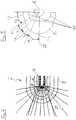
- Fig. 2 shows the exterior aircraft light unit 2 of Fig. 1 in a navigation light mode of operation.
- the plurality of first light sources 6 do not emit light.
- the two second light sources 12 emit light in the navigation light mode of operation.
- a plurality of light rays 22 are depicted, which light rays 22 are emitted from the two second light sources 12.
- the dedicated refractive optical element of the second light source 12 that is arranged on the curved edge of the mounting structure 4 emits light in a range of directions close to the flight direction 16.
- the opening angle 24 of the light emitted from this second light source 12 is about 15° in the first cross-sectional plane, depicted in Fig. 2 .
- the dedicated refractive optical element of the other second light source i.e. of the second light source that is positioned on the leg portion of the mounting structure 4, is shaped to distribute the light from the second light source 12 across an angle of about 95° in the first cross-sectional plane.
- This angle of about 95° is referenced with reference numeral 26.
- the angle 24 and the angle 26 together form an opening angle of about 110° for the exterior aircraft light unit 2 in the first cross-sectional plane in the navigation light mode of operation. This angle of 110° is in line with the generally accepted requirements for wing-tip navigation lights.
- the exterior aircraft light unit 2 can be operated in both an anti-collision mode of operation as well as an navigation mode of operation, which two modes have been discussed with respect to Figs. 1 and 2 above, the exterior aircraft light unit 2 may also be referred to as a combined anti-collision and navigation light unit.
- the two modes of operation may be present at different points in time. However, it is also possible that both modes of operation are present at the same time.
- FIG. 3 some of the components of the exterior aircraft light unit 2 of Figs. 1 and 2 are shown in a perspective, three-dimensional manner.
- the mounting structure 4 the refractive optical element 10 and the two dedicated refractive optical elements 14 are shown in Fig. 3 .
- the refractive optical element 10 covers the plurality of first light sources 6 and as the two dedicated refractive optical elements 14 cover the two associated second light sources 12 in the viewing direction of Fig. 3 , these elements are not visible.
- the lens cover 8 is not shown in Fig. 3 .
- the mounting structure 4 is a rather flat structure, while the refractive optical element 10 and the two dedicated refractive optical elements 14 have a considerably larger extension in the third dimension.
- a second cross-sectional view of the exemplary exterior aircraft light unit 2 of Figs. 1-3 is shown.
- the exterior aircraft light unit 2 is shown in a second cross-sectional plane that is orthogonal to the first cross-sectional plane of Figs. 1 and 2 .
- the second cross-sectional plane is further oriented in such a way with respect to the exterior aircraft light unit 2 that it includes a light emission direction normal to the curved edge 44 of the mounting structure in the first cross-sectional plane of Figs. 1 and 2 .
- the second cross-sectional plane extends through the center of one of the first light sources 6.
- the second cross-sectional plane extends through one of the first light sources 6 that are arranged towards the left in the first cross-sectional plane of Figs. 1 and 2 .
- the lens cover 8 is arranged very closely to the refractive optical element 10, as is depicted in Fig. 4 .
- the mounting structure 4 is shown towards the right.
- the refractive optical element 10 wraps around the first light source 6.
- the lens cover 8 wraps around the refractive optical element 10.
- the cross-sectional view of Figs. 1 and 2 is a horizontal cross-sectional view, when the exterior aircraft light unit 2 is arranged in its operational position in an aircraft
- the cross-sectional view of Fig. 4 is a vertical cross-sectional view, when the exterior aircraft light unit 2 is placed in the aircraft.
- Fig. 4 there are further shown a plurality of exemplary light rays 20, as emitted from the first light source 6 during one of the light flashes in the anti-collision light mode of operation.
- the light rays 20 provide an illustration of how the refractive optical element 10 shapes the vertical light emission distribution of the exterior aircraft light unit 2.
- the refractive optical element 10 is shaped in such a way that the light, emitted by the first light source 6, satisfies the requirements of the Federal Aviation Regulations (FAR) for the vertical light intensity distribution of anti-collision lights.
- FAR Federal Aviation Regulations
- the particular shape of the refractive optical element used for this purpose is described in greater detail with respect to Fig. 5 .
- the light rays 20 reach the lens cover 8 at angles that are very close to normal. This is mainly due to the first light source 6 being positioned close to the center of the curvature of the lens cover in the depicted cross-sectional plane. In this way, the refractive impact of the lens cover 8 is kept low.
- Fig. 5 shows the first light source 6 and the refractive optical element 10 of Fig. 4 in an enlarged illustration.
- the cross-sectional plane through these elements is the same as in Fig. 4 .
- the inner surface of the refractive optical element 10 consists of three concave portions 120. These three concave portions 120 form a symmetric inner surface with respect to the direction normal to the first light source 6, i.e. with respect to the horizontal direction in the cross-sectional plane of Fig. 5 , when the exterior aircraft light unit 2 is installed in an aircraft.
- the two concave portions 120 arranged in a symmetric manner with respect to the normal direction 28 cover respective opening angles of 48°, measured from the center of the first light source 6. These two concave portions 120 are circular.
- the third concave portion 120, disposed between the other two concave portions 120 covers an opening angle of 84°.
- the outer surface of the refractive optical element 10 is also symmetric with respect to the normal direction 28.
- the refractive optical element 10 comprises four distinct outer surface portions, two of which are concave and two of which are convex.
- the upper half of the refractive optical element 10, as shown in Fig. 5 comprises a first outer surface portion 102, which is convex, a second outer surface portion 104, which is concave, a third outer surface portion 106, which is also concave, and a fourth outer surface portion 108, which is again convex.
- the first outer surface portion 102 extends over an opening angle of 32°, measured with respect to the center of the first light source 6 and referenced with reference numeral 112.
- the second outer surface portion 104 extends over an opening angle of 16°, referenced with reference numeral 114.
- the third outer surface portion 106 extends over an opening angle of 17°, referenced with reference numeral 116.
- the fourth outer surface portion 108 extends over an opening angle of 25°, referenced with reference numeral 118.
- the inner and outer surfaces of the refractive optical element 10 collect the light emitted from the first light source 6 in an angular range of ⁇ 45° with respect to the horizontal direction 28 and concentrate it between ⁇ 22.5° for achieving a high peak intensity.
- the inner and outer surfaces of the refractive optical element 10 of the exemplary embodiment of Fig. 5 are shaped in such a way that they transform the light emission distribution of the first light source 6 into a light emission distribution that satisfies the requirements of the Federal Aviation Regulations (FAR) for the vertical light intensity distribution of anti-collision lights.
- FAR Federal Aviation Regulations
- the exemplary combination of convex and concave surface portions allows for a particularly power-efficient way of satisfying the FAR requirements.
- the given shapes of the inner and outer surfaces of the refractive optical element allow for a very efficient satisfaction of the FAR requirements for the vertical light intensity distribution of anti-collision lights.
- the requirements may be satisfied in a very targeted manner, meaning that not much more light is emitted for any particular direction than required by the FAR requirements. Accordingly, the light from the plurality of first light sources 6 is put to a very efficient use, keeping the overall power consumption of the exterior aircraft light unit 2 low.
Landscapes
- Engineering & Computer Science (AREA)
- General Engineering & Computer Science (AREA)
- Aviation & Aerospace Engineering (AREA)
- Traffic Control Systems (AREA)
- Non-Portable Lighting Devices Or Systems Thereof (AREA)
Claims (14)
- Luftfahrzeug-Außenbeleuchtungseinheit (2), umfassend:eine Befestigungsstruktur (4),eine Mehrzahl von ersten Lichtquellen (6), die an der Befestigungsstruktur (4) angeordnet sind, undeine Linsenabdeckung (8), die über der Mehrzahl von ersten Lichtquellen (6) angeordnet ist, wobei die Linsenabdeckung (8) zumindest in einer ersten Querschnittsebene eine konvexe Form aufweist,wobei die Luftfahrzeug-Außenbeleuchtungseinheit (2) konfiguriert ist, um in einer aerodynamischen Struktur eines Flugzeugflügels installiert zu werden,dadurch gekennzeichnet, dassdie Mehrzahl von ersten Lichtquellen (6) in einem gekrümmten Muster angeordnet sind, wobei das gekrümmte Muster die gleiche Krümmungsrichtung wie die konvexe Form der Linsenabdeckung (8) in der ersten Querschnittsebene aufweist und wobei die jeweiligen senkrechten Lichtemissionsrichtungen (28) jeder der Mehrzahl von ersten Lichtquellen (6) relativ voneinander weggewinkelt sind und in der ersten Querschnittsebene zur Linsenabdeckung (6) hin ausgerichtet sind, unddie Luftfahrzeug-Außenbeleuchtungseinheit (2) ferner ein refraktives optisches Element (10) umfasst, das zwischen der Mehrzahl von ersten Lichtquellen (6) und der Linsenabdeckung (8) angeordnet ist, wobei das refraktive optische Element (10) eine gekrümmte Form aufweist, die sich entlang des gekrümmten Musters der Mehrzahl von Lichtquellen (6)erstreckt.
- Luftfahrzeug-Außenbeleuchtungseinheit (2) nach Anspruch 1, wobei die Mehrzahl von ersten Lichtquellen (6) als eine Reihe von benachbarten Lichtquellen in dem gekrümmten Muster angeordnet sind.
- Luftfahrzeug-Außenbeleuchtungseinheit (2) nach einem der vorstehenden Ansprüche, wobei ein Krümmungsradius der Linsenabdeckung (8) zwischen 100 % und 200 %, insbesondere zwischen 100 % und 140 %, eines Krümmungsradius des gekrümmten Musters entlang mindestens 80 % des gekrümmten Musters in der ersten Querschnittsebene beträgt.
- Luftfahrzeug-Außenbeleuchtungseinheit (2) nach einem der vorstehenden Ansprüche, wobei das gekrümmte Muster und die Linsenabdeckung (8) solche entsprechenden Formen aufweisen, dass Licht, das von der Mehrzahl von ersten Lichtquellen (6) in einer Richtung senkrecht zu dem gekrümmten Muster emittiert wird, die Linsenabdeckung (8) in einem Winkel von weniger als 45 °, insbesondere von weniger als 30 °, in Bezug auf eine Richtung senkrecht zu der Linsenabdeckung (8) erreicht.
- Luftfahrzeug-Außenbeleuchtungseinheit (2) nach einem der vorstehenden Ansprüche, wobei die Linsenabdeckung (8) eine konvexe Form in einer Mehrzahl von zweiten Querschnittsebenen aufweist, die senkrecht zu der ersten Querschnittsebene sind und sich durch die Mehrzahl von ersten Lichtquellen (6) erstrecken.
- Luftfahrzeug-Außenbeleuchtungseinheit (2) nach Anspruch 5, wobei die Mehrzahl von ersten Lichtquellen (6) derart von der Linsenabdeckung (8) beabstandet sind, dass das Licht, das von der Mehrzahl von ersten Lichtquellen (6) in der Mehrzahl von zweiten Querschnittsebenen in einem Winkel von weniger als 45 ° in Bezug auf eine Richtung senkrecht zu dem gekrümmten Muster emittiert wird, die Linsenabdeckung (8) in einem Winkel von weniger als 30 °, insbesondere von weniger als 20 °, in Bezug auf eine Richtung senkrecht zu der Linsenabdeckung (8) erreicht.
- Luftfahrzeug-Außenbeleuchtungseinheit (2) nach Anspruch 5 oder 6, wobei für jede der Mehrzahl von ersten Lichtquellen (6) ein Abstand zwischen der jeweiligen ersten Lichtquelle und der Linsenabdeckung (8) weniger als 200 %, insbesondere zwischen 50 % und 150 %, eines Krümmungsradius der Linsenabdeckung (8) in der jeweiligen zweiten Querschnittsebene beträgt.
- Luftfahrzeug-Außenbeleuchtungseinheit (2) nach einem der vorstehenden Ansprüche, wobei das refraktive optische Element (10) in mindestens einer zweiten Querschnittsebene senkrecht zur ersten Querschnittsebene eine Kombination aus konvexen und konkaven äußeren Oberflächenabschnitten (102, 104, 106, 108) umfasst, die sich und durch eine der Mehrzahl von ersten Lichtquellen (6) erstrecken.
- Luftfahrzeug-Außenbeleuchtungseinheit (2) nach einem der vorstehenden Ansprüche, konfiguriert, um an einem Luftfahrzeug montiert zu werden, wobei die erste Querschnittsebene horizontal ausgerichtet ist.
- Luftfahrzeug-Außenbeleuchtungseinheit (2) nach einem der vorstehenden Ansprüche, wobei die Luftfahrzeug-Außenbeleuchtungseinheit (2) eines von einer Antikollisionslichteinheit und einer Leuchtfeuereinheit ist.
- Luftfahrzeug-Außenbeleuchtungseinheit (2) nach einem der vorstehenden Ansprüche, ferner umfassend:
mindestens eine zweite Lichtquelle (12), die auf der Befestigungsstruktur (4) angeordnet und neben dem gekrümmten Muster der Mehrzahl von ersten Lichtquellen (6) positioniert ist. - Luftfahrzeug-Außenbeleuchtungseinheit (2) nach Anspruch 11, wobei jede der mindestens einen zweiten Lichtquelle (6) ein eigenes refraktives optisches Element (14) aufweist, das zwischen der jeweiligen zweiten Lichtquelle (12) und der Linsenabdeckung (8) angeordnet ist.
- Luftfahrzeug-Außenbeleuchtungseinheit (2) nach Anspruch 11 oder 12, wobei die Luftfahrzeug-Außenbeleuchtungseinheit (2) eines von einer kombinierten Antikollisions- und Navigationslichteinheit und einer kombinierten Leuchtfeuer-und Navigationslichteinheit ist, wobei die Mehrzahl von ersten Lichtquellen (6) als eines von einem Antikollisionslicht und einer Leuchtfeuereinheit funktioniert und wobei die mindestens eine zweite Lichtquelle (12) als ein Navigationslicht funktioniert.
- Luftfahrzeug, wie etwa ein Flugzeug, umfassend mindestens eine Luftfahrzeug-Außenbeleuchtungseinheit (2) nach einem der vorstehenden Ansprüche.
Priority Applications (3)
| Application Number | Priority Date | Filing Date | Title |
|---|---|---|---|
| ES14180962.4T ES2689644T3 (es) | 2014-08-14 | 2014-08-14 | Unidad de luz de aeronave exterior y aeronave que comprende la misma |
| EP14180962.4A EP2985228B1 (de) | 2014-08-14 | 2014-08-14 | Außenbeleuchtungseinheit für ein Flugzeug und Flugzeug damit |
| US14/825,907 US9783319B2 (en) | 2014-08-14 | 2015-08-13 | Exterior aircraft light unit and aircraft comprising the same |
Applications Claiming Priority (1)
| Application Number | Priority Date | Filing Date | Title |
|---|---|---|---|
| EP14180962.4A EP2985228B1 (de) | 2014-08-14 | 2014-08-14 | Außenbeleuchtungseinheit für ein Flugzeug und Flugzeug damit |
Publications (2)
| Publication Number | Publication Date |
|---|---|
| EP2985228A1 EP2985228A1 (de) | 2016-02-17 |
| EP2985228B1 true EP2985228B1 (de) | 2018-07-04 |
Family
ID=51383555
Family Applications (1)
| Application Number | Title | Priority Date | Filing Date |
|---|---|---|---|
| EP14180962.4A Active EP2985228B1 (de) | 2014-08-14 | 2014-08-14 | Außenbeleuchtungseinheit für ein Flugzeug und Flugzeug damit |
Country Status (3)
| Country | Link |
|---|---|
| US (1) | US9783319B2 (de) |
| EP (1) | EP2985228B1 (de) |
| ES (1) | ES2689644T3 (de) |
Families Citing this family (5)
| Publication number | Priority date | Publication date | Assignee | Title |
|---|---|---|---|---|
| EP3543145B1 (de) | 2018-03-23 | 2021-08-18 | Goodrich Lighting Systems GmbH | Flugzeugaussenleuchte, flugzeug mit solch einer leuchte und verfahren zum betrieb einer flugzeugaussenleuchte |
| ES2887007T3 (es) * | 2018-09-21 | 2021-12-21 | Goodrich Lighting Systems Gmbh | Luz exterior de aeronave y aeronave que comprende la misma |
| CN109606636A (zh) * | 2018-11-02 | 2019-04-12 | 中国航空工业集团公司西安飞机设计研究所 | 一种通用飞机方向舵复合材料翼尖结构及制造方法 |
| EP3670356B1 (de) * | 2018-12-17 | 2023-08-30 | Goodrich Lighting Systems GmbH | Kombiniertes vorwärtsnavigations- und kollisionsschutzlicht für ein flugzeug und flugzeug damit |
| EP3766787B1 (de) * | 2019-07-14 | 2023-01-04 | Goodrich Lighting Systems GmbH | Verfahren zum anzeigen einer flugrichtung eines luftfahrzeugs, flugrichtungsanzeigesystem für ein luftfahrzeug und luftfahrzeug |
Family Cites Families (7)
| Publication number | Priority date | Publication date | Assignee | Title |
|---|---|---|---|---|
| US6191541B1 (en) * | 1998-10-05 | 2001-02-20 | Godfrey Engineering, Inc. | Solid state tail light for aircraft |
| US20050047167A1 (en) * | 1999-08-04 | 2005-03-03 | Pederson John C. | Warning signal light bar |
| FR2886713A1 (fr) * | 2005-06-06 | 2006-12-08 | Ece Soc Par Actions Simplifiee | Dispositif de signalisation lumineux anti-collision |
| JP5213383B2 (ja) * | 2007-08-09 | 2013-06-19 | シャープ株式会社 | 発光装置およびこれを備える照明装置 |
| US8454212B2 (en) * | 2007-12-28 | 2013-06-04 | Sirio Panel S.P.A. | Anti-collision light for aircraft |
| US20100027281A1 (en) * | 2008-07-31 | 2010-02-04 | Waters Stanley E | LED Anti-Collision Light for Commercial Aircraft |
| CA2874757C (en) * | 2012-05-31 | 2020-12-22 | Bombardier Inc. | Lighting array for an aircraft |
-
2014
- 2014-08-14 EP EP14180962.4A patent/EP2985228B1/de active Active
- 2014-08-14 ES ES14180962.4T patent/ES2689644T3/es active Active
-
2015
- 2015-08-13 US US14/825,907 patent/US9783319B2/en active Active
Non-Patent Citations (1)
| Title |
|---|
| ANONYMOUS: "The New 2014 Generation 5 Cirrus Aircraft - Plane & Pilot Magazine", 28 October 2013 (2013-10-28), XP055436580, Retrieved from the Internet <URL:http://www.planeandpilotmag.com/article/the-new-2014-generation-5-cirrus-aircraft/#.WM_b4nrdfSg, published October 28, 2013> [retrieved on 20171219] * |
Also Published As
| Publication number | Publication date |
|---|---|
| US9783319B2 (en) | 2017-10-10 |
| US20160046389A1 (en) | 2016-02-18 |
| ES2689644T3 (es) | 2018-11-15 |
| EP2985228A1 (de) | 2016-02-17 |
Similar Documents
| Publication | Publication Date | Title |
|---|---|---|
| EP2985228B1 (de) | Außenbeleuchtungseinheit für ein Flugzeug und Flugzeug damit | |
| US7434970B2 (en) | Multi-platform LED-based aircraft rear position light | |
| US11097855B2 (en) | Aircraft beacon light and aircraft comprising an aircraft beacon light | |
| US11479366B2 (en) | Exterior aircraft light, aircraft comprising the same, and method of operating an exterior aircraft light | |
| EP3670356B1 (de) | Kombiniertes vorwärtsnavigations- und kollisionsschutzlicht für ein flugzeug und flugzeug damit | |
| EP3476746B1 (de) | Flugzeugnavigationslicht und flugzeug damit | |
| EP3002221B1 (de) | Bodenbeleuchtungseinheit für ein Flugzeug und damit ausgerüstetes Flugzeug | |
| US9789975B2 (en) | Exterior aircraft light unit and aircraft comprising the same | |
| EP3284683B1 (de) | Äussere luftfahrzeugbeleuchtungseinheit, hubschrauber und flugzeug | |
| EP3498611B1 (de) | Flugzeugleuchtfeuereinheit und satz aus flugzeugleuchtfeuereinheiten | |
| US8956023B1 (en) | Combined wing scan and winglet illumination light unit and aircraft having winglet illumination | |
| EP3168160B1 (de) | Äussere flugzeugbeleuchtungseinheit und flugzeug damit | |
| US11072437B2 (en) | Aircraft beacon light and aircraft comprising the same | |
| US10464692B2 (en) | Exterior aircraft light unit and aircraft comprising the same | |
| EP3428072B1 (de) | Linsenstruktur für lichteinheit, lichteinheit, flugzeug beinhaltend solche lichteinheit und herstellungsverfahren solcher linsenstruktur |
Legal Events
| Date | Code | Title | Description |
|---|---|---|---|
| PUAI | Public reference made under article 153(3) epc to a published international application that has entered the european phase |
Free format text: ORIGINAL CODE: 0009012 |
|
| AK | Designated contracting states |
Kind code of ref document: A1 Designated state(s): AL AT BE BG CH CY CZ DE DK EE ES FI FR GB GR HR HU IE IS IT LI LT LU LV MC MK MT NL NO PL PT RO RS SE SI SK SM TR |
|
| AX | Request for extension of the european patent |
Extension state: BA ME |
|
| 17P | Request for examination filed |
Effective date: 20160817 |
|
| RBV | Designated contracting states (corrected) |
Designated state(s): AL AT BE BG CH CY CZ DE DK EE ES FI FR GB GR HR HU IE IS IT LI LT LU LV MC MK MT NL NO PL PT RO RS SE SI SK SM TR |
|
| R17P | Request for examination filed (corrected) |
Effective date: 20160817 |
|
| 17Q | First examination report despatched |
Effective date: 20170406 |
|
| GRAP | Despatch of communication of intention to grant a patent |
Free format text: ORIGINAL CODE: EPIDOSNIGR1 |
|
| INTG | Intention to grant announced |
Effective date: 20180118 |
|
| GRAS | Grant fee paid |
Free format text: ORIGINAL CODE: EPIDOSNIGR3 |
|
| GRAA | (expected) grant |
Free format text: ORIGINAL CODE: 0009210 |
|
| AK | Designated contracting states |
Kind code of ref document: B1 Designated state(s): AL AT BE BG CH CY CZ DE DK EE ES FI FR GB GR HR HU IE IS IT LI LT LU LV MC MK MT NL NO PL PT RO RS SE SI SK SM TR |
|
| REG | Reference to a national code |
Ref country code: GB Ref legal event code: FG4D |
|
| REG | Reference to a national code |
Ref country code: CH Ref legal event code: EP |
|
| REG | Reference to a national code |
Ref country code: AT Ref legal event code: REF Ref document number: 1014220 Country of ref document: AT Kind code of ref document: T Effective date: 20180715 |
|
| REG | Reference to a national code |
Ref country code: IE Ref legal event code: FG4D |
|
| REG | Reference to a national code |
Ref country code: DE Ref legal event code: R096 Ref document number: 602014027779 Country of ref document: DE |
|
| REG | Reference to a national code |
Ref country code: FR Ref legal event code: PLFP Year of fee payment: 5 |
|
| REG | Reference to a national code |
Ref country code: NL Ref legal event code: MP Effective date: 20180704 |
|
| REG | Reference to a national code |
Ref country code: ES Ref legal event code: FG2A Ref document number: 2689644 Country of ref document: ES Kind code of ref document: T3 Effective date: 20181115 |
|
| REG | Reference to a national code |
Ref country code: LT Ref legal event code: MG4D |
|
| REG | Reference to a national code |
Ref country code: AT Ref legal event code: MK05 Ref document number: 1014220 Country of ref document: AT Kind code of ref document: T Effective date: 20180704 |
|
| PG25 | Lapsed in a contracting state [announced via postgrant information from national office to epo] |
Ref country code: NL Free format text: LAPSE BECAUSE OF FAILURE TO SUBMIT A TRANSLATION OF THE DESCRIPTION OR TO PAY THE FEE WITHIN THE PRESCRIBED TIME-LIMIT Effective date: 20180704 |
|
| PG25 | Lapsed in a contracting state [announced via postgrant information from national office to epo] |
Ref country code: IS Free format text: LAPSE BECAUSE OF FAILURE TO SUBMIT A TRANSLATION OF THE DESCRIPTION OR TO PAY THE FEE WITHIN THE PRESCRIBED TIME-LIMIT Effective date: 20181104 Ref country code: SE Free format text: LAPSE BECAUSE OF FAILURE TO SUBMIT A TRANSLATION OF THE DESCRIPTION OR TO PAY THE FEE WITHIN THE PRESCRIBED TIME-LIMIT Effective date: 20180704 Ref country code: RS Free format text: LAPSE BECAUSE OF FAILURE TO SUBMIT A TRANSLATION OF THE DESCRIPTION OR TO PAY THE FEE WITHIN THE PRESCRIBED TIME-LIMIT Effective date: 20180704 Ref country code: LT Free format text: LAPSE BECAUSE OF FAILURE TO SUBMIT A TRANSLATION OF THE DESCRIPTION OR TO PAY THE FEE WITHIN THE PRESCRIBED TIME-LIMIT Effective date: 20180704 Ref country code: BG Free format text: LAPSE BECAUSE OF FAILURE TO SUBMIT A TRANSLATION OF THE DESCRIPTION OR TO PAY THE FEE WITHIN THE PRESCRIBED TIME-LIMIT Effective date: 20181004 Ref country code: PL Free format text: LAPSE BECAUSE OF FAILURE TO SUBMIT A TRANSLATION OF THE DESCRIPTION OR TO PAY THE FEE WITHIN THE PRESCRIBED TIME-LIMIT Effective date: 20180704 Ref country code: CZ Free format text: LAPSE BECAUSE OF FAILURE TO SUBMIT A TRANSLATION OF THE DESCRIPTION OR TO PAY THE FEE WITHIN THE PRESCRIBED TIME-LIMIT Effective date: 20180704 Ref country code: FI Free format text: LAPSE BECAUSE OF FAILURE TO SUBMIT A TRANSLATION OF THE DESCRIPTION OR TO PAY THE FEE WITHIN THE PRESCRIBED TIME-LIMIT Effective date: 20180704 Ref country code: GR Free format text: LAPSE BECAUSE OF FAILURE TO SUBMIT A TRANSLATION OF THE DESCRIPTION OR TO PAY THE FEE WITHIN THE PRESCRIBED TIME-LIMIT Effective date: 20181005 Ref country code: NO Free format text: LAPSE BECAUSE OF FAILURE TO SUBMIT A TRANSLATION OF THE DESCRIPTION OR TO PAY THE FEE WITHIN THE PRESCRIBED TIME-LIMIT Effective date: 20181004 Ref country code: AT Free format text: LAPSE BECAUSE OF FAILURE TO SUBMIT A TRANSLATION OF THE DESCRIPTION OR TO PAY THE FEE WITHIN THE PRESCRIBED TIME-LIMIT Effective date: 20180704 |
|
| PG25 | Lapsed in a contracting state [announced via postgrant information from national office to epo] |
Ref country code: LV Free format text: LAPSE BECAUSE OF FAILURE TO SUBMIT A TRANSLATION OF THE DESCRIPTION OR TO PAY THE FEE WITHIN THE PRESCRIBED TIME-LIMIT Effective date: 20180704 Ref country code: HR Free format text: LAPSE BECAUSE OF FAILURE TO SUBMIT A TRANSLATION OF THE DESCRIPTION OR TO PAY THE FEE WITHIN THE PRESCRIBED TIME-LIMIT Effective date: 20180704 Ref country code: AL Free format text: LAPSE BECAUSE OF FAILURE TO SUBMIT A TRANSLATION OF THE DESCRIPTION OR TO PAY THE FEE WITHIN THE PRESCRIBED TIME-LIMIT Effective date: 20180704 |
|
| REG | Reference to a national code |
Ref country code: CH Ref legal event code: PL |
|
| REG | Reference to a national code |
Ref country code: DE Ref legal event code: R097 Ref document number: 602014027779 Country of ref document: DE |
|
| PG25 | Lapsed in a contracting state [announced via postgrant information from national office to epo] |
Ref country code: RO Free format text: LAPSE BECAUSE OF FAILURE TO SUBMIT A TRANSLATION OF THE DESCRIPTION OR TO PAY THE FEE WITHIN THE PRESCRIBED TIME-LIMIT Effective date: 20180704 Ref country code: IT Free format text: LAPSE BECAUSE OF FAILURE TO SUBMIT A TRANSLATION OF THE DESCRIPTION OR TO PAY THE FEE WITHIN THE PRESCRIBED TIME-LIMIT Effective date: 20180704 Ref country code: EE Free format text: LAPSE BECAUSE OF FAILURE TO SUBMIT A TRANSLATION OF THE DESCRIPTION OR TO PAY THE FEE WITHIN THE PRESCRIBED TIME-LIMIT Effective date: 20180704 Ref country code: CH Free format text: LAPSE BECAUSE OF NON-PAYMENT OF DUE FEES Effective date: 20180831 Ref country code: LU Free format text: LAPSE BECAUSE OF NON-PAYMENT OF DUE FEES Effective date: 20180814 Ref country code: LI Free format text: LAPSE BECAUSE OF NON-PAYMENT OF DUE FEES Effective date: 20180831 Ref country code: MC Free format text: LAPSE BECAUSE OF FAILURE TO SUBMIT A TRANSLATION OF THE DESCRIPTION OR TO PAY THE FEE WITHIN THE PRESCRIBED TIME-LIMIT Effective date: 20180704 |
|
| PLBE | No opposition filed within time limit |
Free format text: ORIGINAL CODE: 0009261 |
|
| REG | Reference to a national code |
Ref country code: BE Ref legal event code: MM Effective date: 20180831 |
|
| STAA | Information on the status of an ep patent application or granted ep patent |
Free format text: STATUS: NO OPPOSITION FILED WITHIN TIME LIMIT |
|
| REG | Reference to a national code |
Ref country code: IE Ref legal event code: MM4A |
|
| PG25 | Lapsed in a contracting state [announced via postgrant information from national office to epo] |
Ref country code: SK Free format text: LAPSE BECAUSE OF FAILURE TO SUBMIT A TRANSLATION OF THE DESCRIPTION OR TO PAY THE FEE WITHIN THE PRESCRIBED TIME-LIMIT Effective date: 20180704 Ref country code: SM Free format text: LAPSE BECAUSE OF FAILURE TO SUBMIT A TRANSLATION OF THE DESCRIPTION OR TO PAY THE FEE WITHIN THE PRESCRIBED TIME-LIMIT Effective date: 20180704 Ref country code: DK Free format text: LAPSE BECAUSE OF FAILURE TO SUBMIT A TRANSLATION OF THE DESCRIPTION OR TO PAY THE FEE WITHIN THE PRESCRIBED TIME-LIMIT Effective date: 20180704 |
|
| 26N | No opposition filed |
Effective date: 20190405 |
|
| PG25 | Lapsed in a contracting state [announced via postgrant information from national office to epo] |
Ref country code: IE Free format text: LAPSE BECAUSE OF NON-PAYMENT OF DUE FEES Effective date: 20180814 |
|
| PG25 | Lapsed in a contracting state [announced via postgrant information from national office to epo] |
Ref country code: BE Free format text: LAPSE BECAUSE OF NON-PAYMENT OF DUE FEES Effective date: 20180831 Ref country code: SI Free format text: LAPSE BECAUSE OF FAILURE TO SUBMIT A TRANSLATION OF THE DESCRIPTION OR TO PAY THE FEE WITHIN THE PRESCRIBED TIME-LIMIT Effective date: 20180704 |
|
| PG25 | Lapsed in a contracting state [announced via postgrant information from national office to epo] |
Ref country code: MT Free format text: LAPSE BECAUSE OF NON-PAYMENT OF DUE FEES Effective date: 20180814 |
|
| PG25 | Lapsed in a contracting state [announced via postgrant information from national office to epo] |
Ref country code: TR Free format text: LAPSE BECAUSE OF FAILURE TO SUBMIT A TRANSLATION OF THE DESCRIPTION OR TO PAY THE FEE WITHIN THE PRESCRIBED TIME-LIMIT Effective date: 20180704 |
|
| PG25 | Lapsed in a contracting state [announced via postgrant information from national office to epo] |
Ref country code: PT Free format text: LAPSE BECAUSE OF FAILURE TO SUBMIT A TRANSLATION OF THE DESCRIPTION OR TO PAY THE FEE WITHIN THE PRESCRIBED TIME-LIMIT Effective date: 20180704 |
|
| PG25 | Lapsed in a contracting state [announced via postgrant information from national office to epo] |
Ref country code: HU Free format text: LAPSE BECAUSE OF FAILURE TO SUBMIT A TRANSLATION OF THE DESCRIPTION OR TO PAY THE FEE WITHIN THE PRESCRIBED TIME-LIMIT; INVALID AB INITIO Effective date: 20140814 Ref country code: MK Free format text: LAPSE BECAUSE OF NON-PAYMENT OF DUE FEES Effective date: 20180704 Ref country code: CY Free format text: LAPSE BECAUSE OF FAILURE TO SUBMIT A TRANSLATION OF THE DESCRIPTION OR TO PAY THE FEE WITHIN THE PRESCRIBED TIME-LIMIT Effective date: 20180704 |
|
| P01 | Opt-out of the competence of the unified patent court (upc) registered |
Effective date: 20230630 |
|
| PGFP | Annual fee paid to national office [announced via postgrant information from national office to epo] |
Ref country code: GB Payment date: 20230720 Year of fee payment: 10 Ref country code: ES Payment date: 20230901 Year of fee payment: 10 |
|
| PGFP | Annual fee paid to national office [announced via postgrant information from national office to epo] |
Ref country code: FR Payment date: 20230720 Year of fee payment: 10 Ref country code: DE Payment date: 20230720 Year of fee payment: 10 |