EP3205530A1 - Method for operating an at least temporarily electrically drivable motor vehicle, control device for a motor vehicle and corresponding motor vehicle - Google Patents
Method for operating an at least temporarily electrically drivable motor vehicle, control device for a motor vehicle and corresponding motor vehicle Download PDFInfo
- Publication number
- EP3205530A1 EP3205530A1 EP17153673.3A EP17153673A EP3205530A1 EP 3205530 A1 EP3205530 A1 EP 3205530A1 EP 17153673 A EP17153673 A EP 17153673A EP 3205530 A1 EP3205530 A1 EP 3205530A1
- Authority
- EP
- European Patent Office
- Prior art keywords
- motor vehicle
- vehicle
- distance
- charging line
- control
- Prior art date
- Legal status (The legal status is an assumption and is not a legal conclusion. Google has not performed a legal analysis and makes no representation as to the accuracy of the status listed.)
- Granted
Links
- 238000000034 method Methods 0.000 title claims abstract description 28
- 238000013459 approach Methods 0.000 description 4
- 230000003287 optical effect Effects 0.000 description 3
- 238000005265 energy consumption Methods 0.000 description 2
- 238000004146 energy storage Methods 0.000 description 2
- 230000000977 initiatory effect Effects 0.000 description 2
- 230000005540 biological transmission Effects 0.000 description 1
- 238000002485 combustion reaction Methods 0.000 description 1
- 238000004891 communication Methods 0.000 description 1
- 238000001514 detection method Methods 0.000 description 1
- 238000011161 development Methods 0.000 description 1
- 238000006073 displacement reaction Methods 0.000 description 1
- 230000007613 environmental effect Effects 0.000 description 1
- 238000012546 transfer Methods 0.000 description 1
- 230000001960 triggered effect Effects 0.000 description 1
- 238000002604 ultrasonography Methods 0.000 description 1
Images

Classifications
-
- B—PERFORMING OPERATIONS; TRANSPORTING
- B60—VEHICLES IN GENERAL
- B60W—CONJOINT CONTROL OF VEHICLE SUB-UNITS OF DIFFERENT TYPE OR DIFFERENT FUNCTION; CONTROL SYSTEMS SPECIALLY ADAPTED FOR HYBRID VEHICLES; ROAD VEHICLE DRIVE CONTROL SYSTEMS FOR PURPOSES NOT RELATED TO THE CONTROL OF A PARTICULAR SUB-UNIT
- B60W30/00—Purposes of road vehicle drive control systems not related to the control of a particular sub-unit, e.g. of systems using conjoint control of vehicle sub-units, or advanced driver assistance systems for ensuring comfort, stability and safety or drive control systems for propelling or retarding the vehicle
- B60W30/14—Adaptive cruise control
-
- B—PERFORMING OPERATIONS; TRANSPORTING
- B60—VEHICLES IN GENERAL
- B60L—PROPULSION OF ELECTRICALLY-PROPELLED VEHICLES; SUPPLYING ELECTRIC POWER FOR AUXILIARY EQUIPMENT OF ELECTRICALLY-PROPELLED VEHICLES; ELECTRODYNAMIC BRAKE SYSTEMS FOR VEHICLES IN GENERAL; MAGNETIC SUSPENSION OR LEVITATION FOR VEHICLES; MONITORING OPERATING VARIABLES OF ELECTRICALLY-PROPELLED VEHICLES; ELECTRIC SAFETY DEVICES FOR ELECTRICALLY-PROPELLED VEHICLES
- B60L5/00—Current collectors for power supply lines of electrically-propelled vehicles
- B60L5/38—Current collectors for power supply lines of electrically-propelled vehicles for collecting current from conductor rails
-
- B—PERFORMING OPERATIONS; TRANSPORTING
- B60—VEHICLES IN GENERAL
- B60L—PROPULSION OF ELECTRICALLY-PROPELLED VEHICLES; SUPPLYING ELECTRIC POWER FOR AUXILIARY EQUIPMENT OF ELECTRICALLY-PROPELLED VEHICLES; ELECTRODYNAMIC BRAKE SYSTEMS FOR VEHICLES IN GENERAL; MAGNETIC SUSPENSION OR LEVITATION FOR VEHICLES; MONITORING OPERATING VARIABLES OF ELECTRICALLY-PROPELLED VEHICLES; ELECTRIC SAFETY DEVICES FOR ELECTRICALLY-PROPELLED VEHICLES
- B60L15/00—Methods, circuits, or devices for controlling the traction-motor speed of electrically-propelled vehicles
- B60L15/20—Methods, circuits, or devices for controlling the traction-motor speed of electrically-propelled vehicles for control of the vehicle or its driving motor to achieve a desired performance, e.g. speed, torque, programmed variation of speed
-
- B—PERFORMING OPERATIONS; TRANSPORTING
- B60—VEHICLES IN GENERAL
- B60L—PROPULSION OF ELECTRICALLY-PROPELLED VEHICLES; SUPPLYING ELECTRIC POWER FOR AUXILIARY EQUIPMENT OF ELECTRICALLY-PROPELLED VEHICLES; ELECTRODYNAMIC BRAKE SYSTEMS FOR VEHICLES IN GENERAL; MAGNETIC SUSPENSION OR LEVITATION FOR VEHICLES; MONITORING OPERATING VARIABLES OF ELECTRICALLY-PROPELLED VEHICLES; ELECTRIC SAFETY DEVICES FOR ELECTRICALLY-PROPELLED VEHICLES
- B60L15/00—Methods, circuits, or devices for controlling the traction-motor speed of electrically-propelled vehicles
- B60L15/32—Control or regulation of multiple-unit electrically-propelled vehicles
- B60L15/38—Control or regulation of multiple-unit electrically-propelled vehicles with automatic control
-
- B—PERFORMING OPERATIONS; TRANSPORTING
- B60—VEHICLES IN GENERAL
- B60L—PROPULSION OF ELECTRICALLY-PROPELLED VEHICLES; SUPPLYING ELECTRIC POWER FOR AUXILIARY EQUIPMENT OF ELECTRICALLY-PROPELLED VEHICLES; ELECTRODYNAMIC BRAKE SYSTEMS FOR VEHICLES IN GENERAL; MAGNETIC SUSPENSION OR LEVITATION FOR VEHICLES; MONITORING OPERATING VARIABLES OF ELECTRICALLY-PROPELLED VEHICLES; ELECTRIC SAFETY DEVICES FOR ELECTRICALLY-PROPELLED VEHICLES
- B60L50/00—Electric propulsion with power supplied within the vehicle
- B60L50/50—Electric propulsion with power supplied within the vehicle using propulsion power supplied by batteries or fuel cells
- B60L50/53—Electric propulsion with power supplied within the vehicle using propulsion power supplied by batteries or fuel cells in combination with an external power supply, e.g. from overhead contact lines
-
- B—PERFORMING OPERATIONS; TRANSPORTING
- B60—VEHICLES IN GENERAL
- B60L—PROPULSION OF ELECTRICALLY-PROPELLED VEHICLES; SUPPLYING ELECTRIC POWER FOR AUXILIARY EQUIPMENT OF ELECTRICALLY-PROPELLED VEHICLES; ELECTRODYNAMIC BRAKE SYSTEMS FOR VEHICLES IN GENERAL; MAGNETIC SUSPENSION OR LEVITATION FOR VEHICLES; MONITORING OPERATING VARIABLES OF ELECTRICALLY-PROPELLED VEHICLES; ELECTRIC SAFETY DEVICES FOR ELECTRICALLY-PROPELLED VEHICLES
- B60L53/00—Methods of charging batteries, specially adapted for electric vehicles; Charging stations or on-board charging equipment therefor; Exchange of energy storage elements in electric vehicles
-
- B—PERFORMING OPERATIONS; TRANSPORTING
- B60—VEHICLES IN GENERAL
- B60L—PROPULSION OF ELECTRICALLY-PROPELLED VEHICLES; SUPPLYING ELECTRIC POWER FOR AUXILIARY EQUIPMENT OF ELECTRICALLY-PROPELLED VEHICLES; ELECTRODYNAMIC BRAKE SYSTEMS FOR VEHICLES IN GENERAL; MAGNETIC SUSPENSION OR LEVITATION FOR VEHICLES; MONITORING OPERATING VARIABLES OF ELECTRICALLY-PROPELLED VEHICLES; ELECTRIC SAFETY DEVICES FOR ELECTRICALLY-PROPELLED VEHICLES
- B60L9/00—Electric propulsion with power supply external to the vehicle
-
- B—PERFORMING OPERATIONS; TRANSPORTING
- B60—VEHICLES IN GENERAL
- B60Q—ARRANGEMENT OF SIGNALLING OR LIGHTING DEVICES, THE MOUNTING OR SUPPORTING THEREOF OR CIRCUITS THEREFOR, FOR VEHICLES IN GENERAL
- B60Q1/00—Arrangement of optical signalling or lighting devices, the mounting or supporting thereof or circuits therefor
- B60Q1/26—Arrangement of optical signalling or lighting devices, the mounting or supporting thereof or circuits therefor the devices being primarily intended to indicate the vehicle, or parts thereof, or to give signals, to other traffic
- B60Q1/34—Arrangement of optical signalling or lighting devices, the mounting or supporting thereof or circuits therefor the devices being primarily intended to indicate the vehicle, or parts thereof, or to give signals, to other traffic for indicating change of drive direction
- B60Q1/346—Arrangement of optical signalling or lighting devices, the mounting or supporting thereof or circuits therefor the devices being primarily intended to indicate the vehicle, or parts thereof, or to give signals, to other traffic for indicating change of drive direction with automatic actuation
-
- B—PERFORMING OPERATIONS; TRANSPORTING
- B60—VEHICLES IN GENERAL
- B60Q—ARRANGEMENT OF SIGNALLING OR LIGHTING DEVICES, THE MOUNTING OR SUPPORTING THEREOF OR CIRCUITS THEREFOR, FOR VEHICLES IN GENERAL
- B60Q1/00—Arrangement of optical signalling or lighting devices, the mounting or supporting thereof or circuits therefor
- B60Q1/26—Arrangement of optical signalling or lighting devices, the mounting or supporting thereof or circuits therefor the devices being primarily intended to indicate the vehicle, or parts thereof, or to give signals, to other traffic
- B60Q1/50—Arrangement of optical signalling or lighting devices, the mounting or supporting thereof or circuits therefor the devices being primarily intended to indicate the vehicle, or parts thereof, or to give signals, to other traffic for indicating other intentions or conditions, e.g. request for waiting or overtaking
- B60Q1/508—Arrangement of optical signalling or lighting devices, the mounting or supporting thereof or circuits therefor the devices being primarily intended to indicate the vehicle, or parts thereof, or to give signals, to other traffic for indicating other intentions or conditions, e.g. request for waiting or overtaking specific to vehicles driving in fleets or convoys
-
- B—PERFORMING OPERATIONS; TRANSPORTING
- B60—VEHICLES IN GENERAL
- B60W—CONJOINT CONTROL OF VEHICLE SUB-UNITS OF DIFFERENT TYPE OR DIFFERENT FUNCTION; CONTROL SYSTEMS SPECIALLY ADAPTED FOR HYBRID VEHICLES; ROAD VEHICLE DRIVE CONTROL SYSTEMS FOR PURPOSES NOT RELATED TO THE CONTROL OF A PARTICULAR SUB-UNIT
- B60W30/00—Purposes of road vehicle drive control systems not related to the control of a particular sub-unit, e.g. of systems using conjoint control of vehicle sub-units, or advanced driver assistance systems for ensuring comfort, stability and safety or drive control systems for propelling or retarding the vehicle
- B60W30/14—Adaptive cruise control
- B60W30/16—Control of distance between vehicles, e.g. keeping a distance to preceding vehicle
- B60W30/165—Automatically following the path of a preceding lead vehicle, e.g. "electronic tow-bar"
-
- B—PERFORMING OPERATIONS; TRANSPORTING
- B60—VEHICLES IN GENERAL
- B60W—CONJOINT CONTROL OF VEHICLE SUB-UNITS OF DIFFERENT TYPE OR DIFFERENT FUNCTION; CONTROL SYSTEMS SPECIALLY ADAPTED FOR HYBRID VEHICLES; ROAD VEHICLE DRIVE CONTROL SYSTEMS FOR PURPOSES NOT RELATED TO THE CONTROL OF A PARTICULAR SUB-UNIT
- B60W30/00—Purposes of road vehicle drive control systems not related to the control of a particular sub-unit, e.g. of systems using conjoint control of vehicle sub-units, or advanced driver assistance systems for ensuring comfort, stability and safety or drive control systems for propelling or retarding the vehicle
- B60W30/18—Propelling the vehicle
- B60W30/18009—Propelling the vehicle related to particular drive situations
- B60W30/18163—Lane change; Overtaking manoeuvres
-
- B—PERFORMING OPERATIONS; TRANSPORTING
- B60—VEHICLES IN GENERAL
- B60W—CONJOINT CONTROL OF VEHICLE SUB-UNITS OF DIFFERENT TYPE OR DIFFERENT FUNCTION; CONTROL SYSTEMS SPECIALLY ADAPTED FOR HYBRID VEHICLES; ROAD VEHICLE DRIVE CONTROL SYSTEMS FOR PURPOSES NOT RELATED TO THE CONTROL OF A PARTICULAR SUB-UNIT
- B60W60/00—Drive control systems specially adapted for autonomous road vehicles
- B60W60/001—Planning or execution of driving tasks
- B60W60/0025—Planning or execution of driving tasks specially adapted for specific operations
-
- G—PHYSICS
- G08—SIGNALLING
- G08G—TRAFFIC CONTROL SYSTEMS
- G08G1/00—Traffic control systems for road vehicles
- G08G1/22—Platooning, i.e. convoy of communicating vehicles
-
- B—PERFORMING OPERATIONS; TRANSPORTING
- B60—VEHICLES IN GENERAL
- B60M—POWER SUPPLY LINES, AND DEVICES ALONG RAILS, FOR ELECTRICALLY- PROPELLED VEHICLES
- B60M1/00—Power supply lines for contact with collector on vehicle
-
- B—PERFORMING OPERATIONS; TRANSPORTING
- B60—VEHICLES IN GENERAL
- B60W—CONJOINT CONTROL OF VEHICLE SUB-UNITS OF DIFFERENT TYPE OR DIFFERENT FUNCTION; CONTROL SYSTEMS SPECIALLY ADAPTED FOR HYBRID VEHICLES; ROAD VEHICLE DRIVE CONTROL SYSTEMS FOR PURPOSES NOT RELATED TO THE CONTROL OF A PARTICULAR SUB-UNIT
- B60W2720/00—Output or target parameters relating to overall vehicle dynamics
- B60W2720/10—Longitudinal speed
-
- B—PERFORMING OPERATIONS; TRANSPORTING
- B60—VEHICLES IN GENERAL
- B60W—CONJOINT CONTROL OF VEHICLE SUB-UNITS OF DIFFERENT TYPE OR DIFFERENT FUNCTION; CONTROL SYSTEMS SPECIALLY ADAPTED FOR HYBRID VEHICLES; ROAD VEHICLE DRIVE CONTROL SYSTEMS FOR PURPOSES NOT RELATED TO THE CONTROL OF A PARTICULAR SUB-UNIT
- B60W2754/00—Output or target parameters relating to objects
- B60W2754/10—Spatial relation or speed relative to objects
- B60W2754/30—Longitudinal distance
-
- Y—GENERAL TAGGING OF NEW TECHNOLOGICAL DEVELOPMENTS; GENERAL TAGGING OF CROSS-SECTIONAL TECHNOLOGIES SPANNING OVER SEVERAL SECTIONS OF THE IPC; TECHNICAL SUBJECTS COVERED BY FORMER USPC CROSS-REFERENCE ART COLLECTIONS [XRACs] AND DIGESTS
- Y02—TECHNOLOGIES OR APPLICATIONS FOR MITIGATION OR ADAPTATION AGAINST CLIMATE CHANGE
- Y02T—CLIMATE CHANGE MITIGATION TECHNOLOGIES RELATED TO TRANSPORTATION
- Y02T10/00—Road transport of goods or passengers
- Y02T10/60—Other road transportation technologies with climate change mitigation effect
- Y02T10/70—Energy storage systems for electromobility, e.g. batteries
-
- Y—GENERAL TAGGING OF NEW TECHNOLOGICAL DEVELOPMENTS; GENERAL TAGGING OF CROSS-SECTIONAL TECHNOLOGIES SPANNING OVER SEVERAL SECTIONS OF THE IPC; TECHNICAL SUBJECTS COVERED BY FORMER USPC CROSS-REFERENCE ART COLLECTIONS [XRACs] AND DIGESTS
- Y02—TECHNOLOGIES OR APPLICATIONS FOR MITIGATION OR ADAPTATION AGAINST CLIMATE CHANGE
- Y02T—CLIMATE CHANGE MITIGATION TECHNOLOGIES RELATED TO TRANSPORTATION
- Y02T10/00—Road transport of goods or passengers
- Y02T10/60—Other road transportation technologies with climate change mitigation effect
- Y02T10/7072—Electromobility specific charging systems or methods for batteries, ultracapacitors, supercapacitors or double-layer capacitors
-
- Y—GENERAL TAGGING OF NEW TECHNOLOGICAL DEVELOPMENTS; GENERAL TAGGING OF CROSS-SECTIONAL TECHNOLOGIES SPANNING OVER SEVERAL SECTIONS OF THE IPC; TECHNICAL SUBJECTS COVERED BY FORMER USPC CROSS-REFERENCE ART COLLECTIONS [XRACs] AND DIGESTS
- Y02—TECHNOLOGIES OR APPLICATIONS FOR MITIGATION OR ADAPTATION AGAINST CLIMATE CHANGE
- Y02T—CLIMATE CHANGE MITIGATION TECHNOLOGIES RELATED TO TRANSPORTATION
- Y02T10/00—Road transport of goods or passengers
- Y02T10/60—Other road transportation technologies with climate change mitigation effect
- Y02T10/72—Electric energy management in electromobility
-
- Y—GENERAL TAGGING OF NEW TECHNOLOGICAL DEVELOPMENTS; GENERAL TAGGING OF CROSS-SECTIONAL TECHNOLOGIES SPANNING OVER SEVERAL SECTIONS OF THE IPC; TECHNICAL SUBJECTS COVERED BY FORMER USPC CROSS-REFERENCE ART COLLECTIONS [XRACs] AND DIGESTS
- Y02—TECHNOLOGIES OR APPLICATIONS FOR MITIGATION OR ADAPTATION AGAINST CLIMATE CHANGE
- Y02T—CLIMATE CHANGE MITIGATION TECHNOLOGIES RELATED TO TRANSPORTATION
- Y02T90/00—Enabling technologies or technologies with a potential or indirect contribution to GHG emissions mitigation
- Y02T90/10—Technologies relating to charging of electric vehicles
- Y02T90/14—Plug-in electric vehicles
Definitions
- the invention relates to a method for operating a motor vehicle, which can be driven electrically at least for a time, on a road.
- the invention further relates to a motor vehicle.
- the method is used to operate the motor vehicle, in particular thus to carry out a driving operation of the motor vehicle on the road.
- the motor vehicle is at least temporarily electrically driven.
- the motor vehicle has at least one electric machine.
- the motor vehicle can thus be designed, for example, as an electric vehicle or as a hybrid vehicle.
- the hybrid vehicle it can be provided by a drive unit, for example an internal combustion engine, in conjunction with a generator, it must be provided completely externally, in particular for the electric vehicle, for example as part of a charging process at a charging station or a socket.
- a vehicle which is equipped with sensors for environmental detection, navigation and collision avoidance, a vehicle control for self-driving the vehicle; a charging system for electrically charging the vehicle; and at least one charging contact, which is functionally connectable with at least one charging contact of the charging station at the charging location; a loading location is used, which is equipped with at least one Charging station having at least one charging contact, which is designed to be functionally connectable to a charging contact of a vehicle to be charged; the vehicle starts at an arbitrary starting point in a transfer area; the vehicle automatically controls a selected loading location; there is a charging contact at the selected charging location between the vehicle and the charging station of the charging location; The vehicle leaves the loading location on its own and drives to a selected takeover area.
- the document shows US 2010/0121509 A1 a vehicle and a traffic device, wherein a plurality of overhead lines is realized, via which the vehicle electrical energy can be provided.
- a control unit performs a fully autonomous driving operation of the motor vehicle upon request of an automatic mode, whereby a transverse control of the motor vehicle is performed such that a previously extended loading arm of the motor vehicle comes into electrical contact with a charging line arranged on or on the road, by means of an energy storage of the motor vehicle is charged and / or a drive device of the motor vehicle is operated to perform the driving operation, and wherein a longitudinal control of the motor vehicle is such that a predetermined longitudinal speed is maintained until a distance of the Motor vehicle reaches a predetermined minimum distance to a vehicle in front.
- the request of the automatic mode can be generated, for example, by the driver of the motor vehicle and / or a driver assistance device.
- a corresponding operating element for example a button, a switch or the like.
- the control unit assumes the driving mode of the motor vehicle, so that the driving operation is subsequently performed fully autonomously.
- the longitudinal control designates the setting of the vehicle speed or longitudinal speed of the motor vehicle, with which the motor vehicle moves in the direction of travel.
- the transverse control comprises, for example, a steering of the motor vehicle, that is to say preferably the selection and setting of a specific steering angle.
- the lateral control of the motor vehicle is performed such that the electrical contact between the charging arm and the charging line is established.
- the charging line is on or on the street.
- the charging line is a guardrail or guardrail or forms part of such.
- the charging line can be designed, for example, as a charging rail.
- the charging line can also be in the form of a catenary or the like.
- the loading arm is designed and arranged on the motor vehicle such that it can interact with the respective configuration of the charging line for producing the electrical contact.
- the loading arm is located on one side or a side wall of the motor vehicle, for example on the left side or the right side.
- the loading arm in the retracted state is preferably arranged in a loading arm receptacle of the motor vehicle, which is particularly preferably closable by means of a cover, for example a flap.
- the loading arm protrudes beyond the side or the side wall of the motor vehicle in the direction of the charging line.
- the loading arm has a level control or level control, by means of which it is adjustable to a certain height, in particular to the height of the present at or present on the road charging line.
- the lateral control is now carried out such that the motor vehicle is directed in the direction of the charging line.
- the loading arm can already be extended when initiating the fully autonomous driving operation or only when it falls below a certain distance through the distance between the motor vehicle and the charging line.
- the aim of the lateral control is first to establish the electrical contact between the charging cable and the loading arm. Once this is done, electrical energy can be made available from the charging line via the charging arm, which can subsequently be used for charging the energy store of the motor vehicle and / or for operating the drive device of the motor vehicle.
- the drive device is used to carry out the driving operation, in particular therefore to provide a torque directed to driving the motor vehicle.
- the transverse control is preferably carried out in the following such that the motor vehicle follows a certain lane and / or the distance between the vehicle Motor vehicle and the charging line remains constant. In this way, a reliable transmission of electrical energy to the motor vehicle can already be realized with a comparatively small loading arm.
- the fully autonomous driving operation of the motor vehicle also includes the longitudinal control. This is carried out such that initially the predetermined longitudinal speed is maintained. Compliance with the longitudinal speed is provided until the instantaneous distance of the motor vehicle to the vehicle in front reaches or falls below the predetermined minimum distance.
- the predetermined longitudinal speed is therefore preferably chosen such that it is greater than the speed of the vehicle in front in order to approach it until the minimum distance exists.
- control unit For carrying out the fully autonomous driving operation is the control unit, which may be part of the driver assistance device of the motor vehicle.
- the control device or the driver assistance device may have at least one sensor, for example a radar sensor, camera sensor, ultrasound sensor or the like.
- the range of the motor vehicle can be significantly increased, because at least temporarily the charging line for the provision of electrical energy is available.
- a fully autonomous driving operation of the motor vehicle is carried out along the charging line.
- the fully autonomous driving operation For the driver of the motor vehicle this gives the impression as if the motor vehicle was guided by the charging line.
- the higher acceptance will be adjusted in particular because the electrical contact between the loading arm and the charging line is automatically produced by means of the lateral control without the driver having to intervene. Especially inexperienced drivers are taken with this approach possible uncertainties.
- the motor vehicle In the convoy mode, the motor vehicle should form a column at least with the vehicle in front, and thus usually maintain a constant distance to it.
- the longitudinal speed is adapted to the speed of the vehicle ahead, so that the longitudinal speed corresponds to this. It can be provided that is switched from the automatic mode only in the Kolonnenfahrtconcesart when the preceding vehicle is also provided or equipped for carrying out the method according to the invention. This can be determined by a corresponding data exchange of the motor vehicle with the preceding vehicle. By maintaining the minimum distance to the vehicle in front can necessary for carrying out the driving energy consumption of the motor vehicle be significantly reduced due to the reduction of air resistance.
- a preferred further embodiment of the invention provides that the longitudinal speed is set to a first default speed upon request of the automatic mode and after setting the charging line by the loading arm to a second default speed. For example, it is provided to use a lower speed until reaching the charging line to allow reliable contacting of the charging line through the charging arm. After contacting, the longitudinal speed can be increased. In such an approach, therefore, the first default speed is less than the second default speed.
- the reverse procedure is possible to first as quickly as possible to make contact of the charging arm to the charging line and subsequently perform an energy-efficient driving operation of the motor vehicle.
- the first default speed may correspond to the second default speed or vice versa.
- the second default speed is greater than the speed of the (possibly) preceding vehicle to reduce the distance therefrom.
- the second default speed has a first value if the motor vehicle does not detect a vehicle in front and a second value if a vehicle in front is detected. The first value is usually lower than the second value. If, therefore, no preceding vehicle is detected, the energy-favorable driving mode should be carried out with the first value of the second preset speed. If, on the other hand, it is determined that there is a preceding vehicle, it should be opened up to the latter in order to reach the Energy consumption by a convoy travel, in particular the initiation of the convoy travel mode to further reduce.
- the second value of the second default speed is correspondingly preferably greater than the instantaneous speed of the preceding vehicle.
- the minimum distance is selected in dependence on the longitudinal speed.
- the minimum distance is determined in such a way that a reliable braking of the vehicle is always possible, regardless of the current driving maneuver of the preceding vehicle.
- the greater the minimum distance the greater the longitudinal velocity.
- a further embodiment of the invention provides that the motor vehicle increases the distance to the preceding vehicle by reducing the longitudinal speed or to a subsequent vehicle by increasing the longitudinal speed to create a traffic gap for the further motor vehicle when displaying a Einscheridios another motor vehicle.
- the further motor vehicle is preferably also provided for carrying out the method according to the invention.
- the Einscherthe is transmitted, for example via a wireless connection, in particular a radio link to the motor vehicle. It indicates that the further motor vehicle wants to shear into the column from the motor vehicle and the preceding vehicle and / or the following vehicle.
- the traffic gap for the further motor vehicle is to be created. This can be realized by increasing the distance to the preceding vehicle or vehicle. In the case of the vehicle ahead, this is the Reduced longitudinal speed and increased in the case of the following vehicle. As soon as the traffic gap has dimensions which enable the cutting in of the further motor vehicle, the lateral control of the further motor vehicle can take place in such a way that it is directed into the traffic gap.
- the further motor vehicle likewise carries out a fully autonomous driving operation within the framework of the automatic mode of operation.
- a further embodiment of the invention provides that the motor vehicle, when displaying a Ausscheriquess the preceding vehicle by reducing the longitudinal speed or the subsequent vehicle by increasing the longitudinal speed increases the distance to this.
- the preceding vehicle or the following vehicle transmits the Ausschern turn wirelessly, so for example via radio.
- the distance is increased to the corresponding vehicle, so for example by reducing the longitudinal speed or by increasing the longitudinal speed. In this way, the vehicle, which would like to move out of the column, this sufficient space is given.
- the Ausschersignal sent out, for example, only to the preceding vehicle, only to the subsequent vehicle or to both the preceding vehicle and the subsequent vehicle.
- the preceding vehicle and / or the following vehicle are designed analogously to the motor vehicle and can therefore serve to carry out the method according to the invention. If this is the case, then the vehicle in front, the following vehicle, or both, preferably each increase their distance from the motor vehicle to allow its Ausscheren easily.
- the motor vehicle can reduce its longitudinal speed in order to increase the distance to the vehicle in front in this way. If the distance to the vehicle in front reaches a sufficient size, then the Ausscheren can be made.
- a preferred development of the invention provides that, in the case of a plurality of motor vehicles traveling in a convoy in a convoy in succession, one of the motor vehicles is selected as the leading vehicle and is arranged as the foremost motor vehicle by correspondingly performing lateral control and / or longitudinal control in the direction of travel.
- the selection of the leading vehicle is preferably done by wireless communication between the vehicles in the convoy.
- properties of motor vehicles such as equipment lists or the like, are exchanged between the motor vehicles.
- the motor vehicles agree on the leading vehicle.
- the motor vehicle with the best equipment, in particular the best sensor equipment is selected as the lead vehicle.
- this performs a fully autonomous driving operation, wherein the lateral control and / or longitudinal control takes place in such a way that it is arranged in the direction of travel of the column as its frontmost motor vehicle.
- the warning signal can be an optical, acoustic or haptic signal.
- the distance of the motor vehicle to the road branch can be done for example by means of the navigation device.
- the distance can also be determined by means of information provided by the charging line. For example, a mark may be provided at a certain distance from the road branch on the charging line. This marking can be, for example, optical or haptic nature.
- the warning signal can be provided to transmit the warning signal only if it is recognized that the motor vehicle is to leave the road at the road junction.
- the warning signal can be transmitted for each preceding road branch. For example, the driver of the motor vehicle can switch between these two different operating modes.
- the invention further relates to a control device for operating a motor vehicle, which can be driven electrically at least for a time, on a road, in particular for carrying out the method according to the preceding embodiments.
- the control unit is designed to perform a fully autonomous driving operation of the motor vehicle upon request of an automatic mode, wherein a lateral control of the motor vehicle is carried out such that a previously extended loading arm of the motor vehicle in electrical contact with a arranged on or on the road charging line occurs, charged by means of the charging line via the charging arm provided electrical energy, an energy storage of the motor vehicle and / or a drive device of the motor vehicle for carrying out the driving operation is operated, and wherein a longitudinal control of the motor vehicle is such that a predetermined longitudinal speed is maintained until a distance of the motor vehicle to a vehicle ahead reaches a predetermined minimum distance.
- the invention relates to a motor vehicle for carrying out the method described above and / or to a control device according to the above statements.
- the latter is again expressly referred to.
- the FIG. 1 shows a plan view of a motor vehicle 1 during a driving operation on a road 2.
- the road 2 has, for example, several lanes 3 and 4, which of course may be more than two lanes.
- the lane 3 is bounded on the one hand by a median strip 5 and on the other hand by a charging line 6.
- the charging line 6 designed as a charging rail in the illustrated embodiment serves to provide electrical energy for the motor vehicle 1.
- the motor vehicle 1 For receiving the electrical energy provided by the charging line 6, the motor vehicle 1 has a charging arm 7, which in the exemplary embodiment shown here is mounted pivotably about a rotational axis 8 on the motor vehicle 1 or a side wall of the motor vehicle 1. On its side facing away from the motor vehicle 1, the loading arm 7 has a contact region 9, with which it can come into electrical contact with the charging line 6.
- the loading arm 7 is, for example, spring-loaded by a spring element 10. The spring force is oriented such that the contact region 9 in the direction of the charging line 6, in particular to the charging line 6, is urged.
- the FIG. 2 shows the motor vehicle 1 in a first driving situation.
- the motor vehicle for example, initially operated manually.
- an automatic mode is requested, for example by a driver of the motor vehicle or by a driver assistance device.
- a control unit of the motor vehicle not shown here, performs a fully autonomous driving operation of the motor vehicle 1.
- a transverse control of the motor vehicle 1 takes place such that the loading arm 7 can come into electrical contact with the charging line 6.
- the lateral control causes a displacement of the motor vehicle 1 on the lane 3 having the charging line 6, in the example shown here of the lane 4 on the lane 3 in the direction of arrow 11.
- the motor vehicle 1 is behind a preceding vehicle 12 or a plurality of preceding vehicles 12, so that the motor vehicle 1 forms a column 13 together with the preceding vehicles 12.
- a longitudinal control of the motor vehicle 1 is performed such that a predetermined longitudinal speed is maintained until the distance of the motor vehicle 1 to the vehicle 12 in front reaches or falls below a predetermined minimum distance.
- the motor vehicle 1 After in the automatic mode, the motor vehicle 1 has been controlled so that the electrical contact between the charging line 6 and the loading arm 7 is present and also the distance of the motor vehicle 1 to the preceding vehicle 12 corresponds to the minimum distance, it can be switched from the automatic mode in the Kolonnenfahrt istsart become.
- the longitudinal speed of the motor vehicle 1 is adapted to the speed of the vehicle 12 in front, so that the distance corresponding to the minimum distance is maintained.
- the fully autonomous driving operation continues to be performed.
- both the lateral control and the longitudinal control are taken over by the control unit.
- the lateral control takes place, for example, such that the distance of the motor vehicle 1 to the charging line 6 remains constant or at least almost constant.
- the longitudinal speed is adjusted so that the distance to the preceding vehicle 12 remains constant.
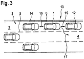
- the FIG. 3 shows the motor vehicle 1 in a second driving situation. Shown is the motor vehicle 1, the preceding vehicle 12 and a subsequent vehicle 14, which drive on the lane 3 as a column 13.
- the vehicles 12 and 14 are preferably operated analogously to the motor vehicle 1.
- the motor vehicle 1 would like to shear out of the column 13. It therefore sends to the preceding vehicle 12 and the following vehicle 14 a Ausschersignal.
- the fully autonomous driving operation for the vehicles 12 and 14 and the motor vehicle 1 is subsequently carried out such that the distance of the vehicles 12 and 14 to the motor vehicle 1 increases. This is indicated by the double arrows 15 and 16. If the distance is sufficiently large, the following motor vehicle 1 can shear out of the column 13 according to the arrow 17. Also, the Ausscheren preferably takes place in the context of fully autonomous driving operation of the motor vehicle 1, ie fully automatically by appropriately performing the lateral control and the longitudinal control.
- the motor vehicle 1 With the motor vehicle 1 described above or the method for its operation, a fully autonomous electrical driving operation of the motor vehicle 1 can also be realized over longer distances.
- the motor vehicle 1 preferably travels exclusively electrically, for which purpose the electrical energy provided by the charging line 6 is used, in particular in the automatic mode and / or the travel mode.
- an energy store of the motor vehicle 1 can be charged with the electrical energy. Due to the fully autonomous driving operation of the motor vehicle 1 and also the driving of the motor vehicle 1 and the vehicles 12 and 14 in the column 13, a particularly energy-saving driving operation can be realized. In addition, by the at least optical guidance of the motor vehicle 1 through the charging line 6 improves the acceptance of the fully autonomous driving operation of the motor vehicle 1.
Abstract
Die Erfindung betrifft ein Verfahren zum Betreiben eines zumindest zeitweise elektrisch antreibbaren Kraftfahrzeugs (1) auf einer Straße (2). Dabei ist vorgesehen, dass ein Steuergerät nach Anforderung einer Automatikbetriebsart einen vollautonomen Fahrbetrieb des Kraftfahrzeugs (1) durchführt, wobei eine Quersteuerung des Kraftfahrzeugs (1) derart durchgeführt wird, dass ein zuvor ausgefahrener Ladearm (7) des Kraftfahrzeugs (1) in elektrischen Kontakt mit einer an oder auf der Straße (2) angeordneten Ladeleitung (6) tritt, wobei mittels von der Ladeleitung (6) über den Ladearm (7) zur Verfügung gestellter elektrischer Energie ein Energiespeicher des Kraftfahrzeugs (1) aufgeladen und/oder eine Antriebseinrichtung des Kraftfahrzeugs (1) zur Durchführung des Fahrbetriebs betrieben wird, und wobei eine Längssteuerung des Kraftfahrzeugs (1) derart erfolgt, dass eine vorgegebene Längsgeschwindigkeit eingehalten wird, bis ein Abstand des Kraftfahrzeugs (1) zu einem vorausfahrenden Fahrzeug (12) einen vorgegebenen Mindestabstand erreicht. Die Erfindung betrifft weiterhin ein Steuergerät für ein Kraftfahrzeug (1) sowie ein Kraftfahrzeug (1).The invention relates to a method for operating a motor vehicle (1) which can be driven electrically at least for a time on a road (2). It is provided that a control unit performs a fully autonomous driving operation of the motor vehicle (1) upon request of an automatic mode, wherein a lateral control of the motor vehicle (1) is carried out such that a previously extended loading arm (7) of the motor vehicle (1) in electrical contact with a charging line (6) arranged on or on the road (2) occurs, wherein an energy store of the motor vehicle (1) is charged by means of electrical energy provided by the charging line (6) via the charging arm (7) and / or a drive device of the motor vehicle (1) is operated to perform the driving operation, and wherein a longitudinal control of the motor vehicle (1) is such that a predetermined longitudinal speed is maintained until a distance of the motor vehicle (1) to a vehicle in front (12) reaches a predetermined minimum distance. The invention further relates to a control device for a motor vehicle (1) and a motor vehicle (1).
Description
Die Erfindung betrifft ein Verfahren zum Betreiben eines zumindest zeitweise elektrisch antreibbaren Kraftfahrzeugs auf einer Straße. Die Erfindung betrifft weiterhin ein Kraftfahrzeug.The invention relates to a method for operating a motor vehicle, which can be driven electrically at least for a time, on a road. The invention further relates to a motor vehicle.
Das Verfahren dient dem Betreiben des Kraftfahrzeugs, insbesondere also dem Durchführen eines Fahrbetriebs des Kraftfahrzeugs auf der Straße. Das Kraftfahrzeug ist zumindest zeitweise elektrisch antreibbar. Hierzu verfügt es über wenigstens eine elektrische Maschine. Das Kraftfahrzeug kann also beispielsweise als Elektrofahrzeug oder als Hybridfahrzeug ausgestaltet sein. Zum Betreiben des Kraftfahrzeugs beziehungsweise zum Durchführen des Fahrbetriebs wird elektrische Energie benötigt. Während diese im Falle des Hybridfahrzeugs von einem Antriebsaggregat, beispielsweise einer Brennkraftmaschine, im Zusammenspiel mit einem Generator bereitgestellt werden kann, muss sie, insbesondere für das Elektrofahrzeug, vollständig von extern bereitgestellt werden, beispielsweise im Rahmen eines Ladevorgangs an einer Ladestation oder einer Steckdose.The method is used to operate the motor vehicle, in particular thus to carry out a driving operation of the motor vehicle on the road. The motor vehicle is at least temporarily electrically driven. For this purpose, it has at least one electric machine. The motor vehicle can thus be designed, for example, as an electric vehicle or as a hybrid vehicle. To operate the motor vehicle or to carry out the driving operation electrical energy is needed. While in the case of the hybrid vehicle it can be provided by a drive unit, for example an internal combustion engine, in conjunction with a generator, it must be provided completely externally, in particular for the electric vehicle, for example as part of a charging process at a charging station or a socket.
So ist beispielsweise aus der Druckschrift
Weiterhin zeigt die Druckschrift
Es ist nun Aufgabe der Erfindung, ein Verfahren zum Betreiben eines zumindest zeitweise elektrisch antreibbaren Kraftfahrzeugs auf einer Straße vorzuschlagen, welches gegenüber bekannten Verfahren Vorteile aufweist, insbesondere einen durchgehenden Fahrbetrieb des Kraftfahrzeugs bei hohem Komfort für einen Fahrer des Kraftfahrzeugs ermöglicht.It is an object of the invention to propose a method for operating a motor vehicle which can be driven at least occasionally on a road, which has advantages over known methods, in particular allows a continuous driving operation of the motor vehicle with high comfort for a driver of the motor vehicle.
Dies wird erfindungsgemäß mit einem Verfahren mit den Merkmalen des Anspruchs 1 erreicht. Dabei ist vorgesehen, dass ein Steuergerät nach Anforderung einer Automatikbetriebsart einen vollautonomen Fahrbetrieb des Kraftfahrzeugs durchführt, wobei eine Quersteuerung des Kraftfahrzeugs derart durchgeführt wird, dass ein zuvor ausgefahrener Ladearm des Kraftfahrzeugs in elektrischen Kontakt mit einer an oder auf der Straße angeordneten Ladeleitung tritt, wobei mittels von der Ladeleitung über den Ladearm zur Verfügung gestellter elektrischer Energie ein Energiespeicher des Kraftfahrzeugs aufgeladen und/oder eine Antriebseinrichtung des Kraftfahrzeugs zur Durchführung des Fahrbetriebs betrieben wird, und wobei eine Längssteuerung des Kraftfahrzeugs derart erfolgt, dass eine vorgegebene Längsgeschwindigkeit eingehalten wird, bis ein Abstand des Kraftfahrzeugs zu einem vorausfahrenden Kraftfahrzeug einen vorgegebenen Mindestabstand erreicht.This is achieved according to the invention by a method having the features of
Die Anforderung der Automatikbetriebsart kann beispielsweise von dem Fahrer des Kraftfahrzeugs und/oder einer Fahrerassistenzeinrichtung erzeugt werden. Zur Erzeugung der Anforderung durch den Fahrer kann ein entsprechendes Bedienelement, beispielsweise ein Knopf, ein Schalter oder dergleichen, vorgesehen sein. Sobald die Anforderung der Automatikbetriebsart vorliegt, übernimmt das Steuergerät den Fahrbetrieb des Kraftfahrzeugs, sodass der Fahrbetrieb nachfolgend vollautonom durchgeführt wird. Darunter ist zu verstehen, dass das Steuergerät sowohl die Quersteuerung als auch die Längssteuerung des Kraftfahrzeugs übernimmt. Die Längssteuerung bezeichnet das Einstellend der Fahrgeschwindigkeit beziehungsweise Längsgeschwindigkeit des Kraftfahrzeugs, mit welcher sich das Kraftfahrzeug in Fahrtrichtung bewegt. Die Quersteuerung umfasst beispielsweise ein Lenken des Kraftfahrzeugs, also bevorzugt das Auswählen und Einstellen eines bestimmten Lenkwinkels.The request of the automatic mode can be generated, for example, by the driver of the motor vehicle and / or a driver assistance device. To generate the request by the driver, a corresponding operating element, for example a button, a switch or the like, may be provided. As soon as the request of the automatic mode is present, the control unit assumes the driving mode of the motor vehicle, so that the driving operation is subsequently performed fully autonomously. This is to be understood that the control unit takes over both the lateral control and the longitudinal control of the motor vehicle. The longitudinal control designates the setting of the vehicle speed or longitudinal speed of the motor vehicle, with which the motor vehicle moves in the direction of travel. The transverse control comprises, for example, a steering of the motor vehicle, that is to say preferably the selection and setting of a specific steering angle.
Die Quersteuerung des Kraftfahrzeugs wird derart durchgeführt, dass der elektrische Kontakt zwischen dem Ladearm und der Ladeleitung hergestellt wird. Die Ladeleitung liegt an oder auf der Straße vor. Beispielsweise ist die Ladeleitung eine Leitplanke beziehungsweise Schutzplanke oder bildet einen Bestandteil einer solchen. In diesem Fall kann die Ladeleitung beispielsweise als Ladeschiene ausgestaltet sein. Selbstverständlich kann jedoch die Ladeleitung auch in Form einer Oberleitung oder dergleichen vorliegen. Der Ladearm ist derart ausgebildet und an dem Kraftfahrzeug angeordnet, dass er mit der jeweiligen Ausgestaltung der Ladeleitung zum Herstellen des elektrischen Kontakts zusammenwirken kann.The lateral control of the motor vehicle is performed such that the electrical contact between the charging arm and the charging line is established. The charging line is on or on the street. For example, the charging line is a guardrail or guardrail or forms part of such. In this case, the charging line can be designed, for example, as a charging rail. Of course, however, the charging line can also be in the form of a catenary or the like. The loading arm is designed and arranged on the motor vehicle such that it can interact with the respective configuration of the charging line for producing the electrical contact.
Bevorzugt liegt der Ladearm an einer Seite beziehungsweise einer Seitenwand des Kraftfahrzeugs vor, beispielsweise auf der linken Seite oder der rechten Seite. Hierbei ist der Ladearm in zurückgezogenem Zustand vorzugsweise in einer Ladearmaufnahme des Kraftfahrzeugs angeordnet, welche besonders bevorzugt mittels einer Abdeckung, beispielsweise einer Klappe, verschließbar ist. In ausgefahrenem Zustand ragt der Ladearm über die Seite beziehungsweise die Seitenwand des Kraftfahrzeugs in Richtung der Ladeleitung über. Bevorzugt verfügt der Ladearm über eine Niveausteuerung oder Niveauregelung, mittels welcher er auf eine bestimmte Höhe einstellbar ist, insbesondere auf die Höhe der momentan an beziehungsweise auf der Straße vorliegenden Ladeleitung.Preferably, the loading arm is located on one side or a side wall of the motor vehicle, for example on the left side or the right side. In this case, the loading arm in the retracted state is preferably arranged in a loading arm receptacle of the motor vehicle, which is particularly preferably closable by means of a cover, for example a flap. In the extended state, the loading arm protrudes beyond the side or the side wall of the motor vehicle in the direction of the charging line. Preferably, the loading arm has a level control or level control, by means of which it is adjustable to a certain height, in particular to the height of the present at or present on the road charging line.
Die Quersteuerung erfolgt nun derart, dass das Kraftfahrzeug in Richtung der Ladeleitung gelenkt wird. Der Ladearm kann bereits bei Einleiten des vollautonomen Fahrbetriebs oder erst bei Unterschreiten eines bestimmten Abstands durch den Abstand zwischen dem Kraftfahrzeug und der Ladeleitung, ausgefahren werden. Ziel der Quersteuerung ist es zunächst, den elektrischen Kontakt zwischen der Ladeleitung und dem Ladearm herzustellen. Sobald dies erfolgt ist, kann von der Ladeleitung über den Ladearm elektrische Energie zur Verfügung gestellt werden, welche nachfolgend zum Laden des Energiespeichers des Kraftfahrzeugs und/oder zum Betreiben der Antriebseinrichtung des Kraftfahrzeugs herangezogen werden kann.The lateral control is now carried out such that the motor vehicle is directed in the direction of the charging line. The loading arm can already be extended when initiating the fully autonomous driving operation or only when it falls below a certain distance through the distance between the motor vehicle and the charging line. The aim of the lateral control is first to establish the electrical contact between the charging cable and the loading arm. Once this is done, electrical energy can be made available from the charging line via the charging arm, which can subsequently be used for charging the energy store of the motor vehicle and / or for operating the drive device of the motor vehicle.
Die Antriebseinrichtung dient der Durchführung des Fahrbetriebs, insbesondere also der Bereitstellung eines auf das Antreiben des Kraftfahrzeugs gerichteten Drehmoments. Sobald der elektrische Kontakt zwischen dem Ladearm und der Ladeleitung vorliegt, wird nachfolgend bevorzugt die Quersteuerung derart durchgeführt, dass das Kraftfahrzeug einer bestimmten Fahrspur folgt und/oder der Abstand zwischen dem Kraftfahrzeug und der Ladeleitung konstant bleibt. Auf diese Art und Weise kann bereits mit einem vergleichsweise kleinen Ladearm eine zuverlässige Übertragung von elektrischer Energie zu dem Kraftfahrzeug realisiert werden.The drive device is used to carry out the driving operation, in particular therefore to provide a torque directed to driving the motor vehicle. As soon as the electrical contact between the charging arm and the charging line is present, the transverse control is preferably carried out in the following such that the motor vehicle follows a certain lane and / or the distance between the vehicle Motor vehicle and the charging line remains constant. In this way, a reliable transmission of electrical energy to the motor vehicle can already be realized with a comparatively small loading arm.
Der vollautonome Fahrbetrieb des Kraftfahrzeugs umfasst auch die Längssteuerung. Diese wird derart durchgeführt, dass zunächst die vorgegebene Längsgeschwindigkeit eingehalten wird. Das Einhalten der Längsgeschwindigkeit ist vorgesehen, bis der momentane Abstand des Kraftfahrzeugs zu dem vorausfahrenden Fahrzeug den vorgegebenen Mindestabstand erreicht oder unterschreitet. Die vorgegebene Längsgeschwindigkeit ist daher bevorzugt derart gewählt, dass sie größer ist als die Geschwindigkeit des vorausfahrenden Fahrzeugs, um sich diesem anzunähern, bis der Mindestabstand vorliegt.The fully autonomous driving operation of the motor vehicle also includes the longitudinal control. This is carried out such that initially the predetermined longitudinal speed is maintained. Compliance with the longitudinal speed is provided until the instantaneous distance of the motor vehicle to the vehicle in front reaches or falls below the predetermined minimum distance. The predetermined longitudinal speed is therefore preferably chosen such that it is greater than the speed of the vehicle in front in order to approach it until the minimum distance exists.
Zur Durchführung des vollautonomen Fahrbetriebs dient das Steuergerät, das Bestandteil der Fahrerassistenzeinrichtung des Kraftfahrzeugs sein kann. Das Steuergerät beziehungsweise die Fahrerassistenzeinrichtung kann über wenigstens einen Sensor verfügen, beispielsweise einen Radarsensor, Kamerasensor, Ultraschallsensor oder dergleichen.For carrying out the fully autonomous driving operation is the control unit, which may be part of the driver assistance device of the motor vehicle. The control device or the driver assistance device may have at least one sensor, for example a radar sensor, camera sensor, ultrasound sensor or the like.
Mit der beschriebenen Vorgehensweise kann die Reichweite des Kraftfahrzeugs deutlich vergrößert werden, weil zumindest zeitweise die Ladeleitung zur Bereitstellung von elektrischer Energie zur Verfügung steht. Gleichzeitig wird entlang der Ladeleitung ein vollautonomer Fahrbetrieb des Kraftfahrzeugs durchgeführt. Für den Fahrer des Kraftfahrzeugs ergibt sich dabei der Eindruck, als ob das Kraftfahrzeug von der Ladeleitung geführt sei. Es wird sich somit eine höhere Akzeptanz bezüglich des vollautonomen Fahrbetriebs einstellen als bei einem freien, ebenfalls vollautonomen Fahrbetrieb des Kraftfahrzeugs, während welchem sich das Kraftfahrzeug frei auf der Straße bewegen kann, ohne mit der Ladeleitung zu interagieren. Die höhere Akzeptanz wird sich insbesondere auch deswegen einstellen, weil der elektrische Kontakt zwischen dem Ladearm und der Ladeleitung mittels der Quersteuerung automatisch hergestellt wird, ohne dass der Fahrer eingreifen muss. Gerade ungeübten Fahrern werden mit dieser Vorgehensweise mögliche Unsicherheiten genommen.With the procedure described, the range of the motor vehicle can be significantly increased, because at least temporarily the charging line for the provision of electrical energy is available. At the same time, a fully autonomous driving operation of the motor vehicle is carried out along the charging line. For the driver of the motor vehicle this gives the impression as if the motor vehicle was guided by the charging line. There will thus be a higher acceptance with respect to the fully autonomous driving operation than with a free, likewise fully autonomous driving operation of the motor vehicle, during which the motor vehicle can move freely on the street without interacting with the charging line. The higher acceptance will be adjusted in particular because the electrical contact between the loading arm and the charging line is automatically produced by means of the lateral control without the driver having to intervene. Especially inexperienced drivers are taken with this approach possible uncertainties.
Im Rahmen einer weiteren Ausgestaltung der Erfindung ist vorgesehen, dass nach dem Erreichen des Mindestabstands durch den Abstand zu dem vorausfahrenden Fahrzeug in eine Kolonnenfahrtbetriebsart umgeschaltet wird, in der die Längsgeschwindigkeit an die Geschwindigkeit des vorausfahrenden Fahrzeugs angeglichen wird, sodass ein dem Mindestabstand entsprechender Abstand eingehalten wird. Auch in der Kolonnenfahrtbetriebsart ist der vollautonome Fahrbetrieb des Kraftfahrzeugs vorgesehen, sodass also das Steuergerät sowohl die Quersteuerung als auch die Längssteuerung des Kraftfahrzeugs übernimmt.As part of a further embodiment of the invention, it is provided that after reaching the minimum distance is switched by the distance to the vehicle ahead in a Kolonnenfahrtbetriebsart in which the longitudinal speed is equalized to the speed of the preceding vehicle, so that a minimum distance corresponding distance is maintained , Also in the convoy mode, the fully autonomous driving operation of the motor vehicle is provided, so that therefore the control unit takes over both the lateral control and the longitudinal control of the motor vehicle.
In der Kolonnenfahrtbetriebsart soll das Kraftfahrzeug zumindest mit dem vorausfahrenden Fahrzeug eine Kolonne bilden, und mithin üblicherweise einen konstanten Abstand zu diesem einhalten. Hierzu wird die Längsgeschwindigkeit an die Geschwindigkeit des vorausfahrenden Fahrzeugs angeglichen, sodass die Längsgeschwindigkeit dieser entspricht. Es kann vorgesehen sein, dass aus der Automatikbetriebsart lediglich dann in die Kolonnenfahrtbetriebsart umgeschaltet wird, wenn das vorausfahrende Fahrzeug ebenfalls zur Ausführung des erfindungsgemäßen Verfahrens vorgesehen beziehungsweise ausgerüstet ist. Dies kann durch einen entsprechenden Datenaustausch des Kraftfahrzeugs mit dem vorausfahrenden Fahrzeug festgestellt werden. Durch das Einhalten des Mindestabstands zu dem vorausfahrenden Fahrzeug kann der zum Durchführen des Fahrbetriebs notwendige Energiebedarf des Kraftfahrzeugs aufgrund der Reduzierung des Luftwiderstands deutlich herabgesetzt werden.In the convoy mode, the motor vehicle should form a column at least with the vehicle in front, and thus usually maintain a constant distance to it. For this purpose, the longitudinal speed is adapted to the speed of the vehicle ahead, so that the longitudinal speed corresponds to this. It can be provided that is switched from the automatic mode only in the Kolonnenfahrtbetriebsart when the preceding vehicle is also provided or equipped for carrying out the method according to the invention. This can be determined by a corresponding data exchange of the motor vehicle with the preceding vehicle. By maintaining the minimum distance to the vehicle in front can necessary for carrying out the driving energy consumption of the motor vehicle be significantly reduced due to the reduction of air resistance.
Eine bevorzugte weitere Ausgestaltung der Erfindung sieht vor, dass die Längsgeschwindigkeit nach Anforderung der Automatikbetriebsart auf eine erste Vorgabegeschwindigkeit und nach dem Kontaktieren der Ladeleitung durch den Ladearm auf eine zweite Vorgabegeschwindigkeit gesetzt wird. Beispielsweise ist es vorgesehen, bis zum Erreichen der Ladeleitung eine geringere Geschwindigkeit zu verwenden, um ein zuverlässiges Kontaktieren der Ladeleitung durch den Ladearm zu ermöglichen. Nach dem Kontaktieren kann die Längsgeschwindigkeit erhöht werden. Bei einer derartigen Vorgehensweise ist folglich die erste Vorgabegeschwindigkeit kleiner als die zweite Vorgabegeschwindigkeit. Selbstverständlich ist jedoch auch die umgekehrte Vorgehensweise möglich, um zunächst möglichst rasch den Kontakt des Ladearms zu der Ladeleitung herzustellen und nachfolgend einen energiegünstigen Fahrbetrieb des Kraftfahrzeugs durchzuführen. Auch kann die erste Vorgabegeschwindigkeit der zweiten Vorgabegeschwindigkeit beziehungsweise umgekehrt entsprechen.A preferred further embodiment of the invention provides that the longitudinal speed is set to a first default speed upon request of the automatic mode and after setting the charging line by the loading arm to a second default speed. For example, it is provided to use a lower speed until reaching the charging line to allow reliable contacting of the charging line through the charging arm. After contacting, the longitudinal speed can be increased. In such an approach, therefore, the first default speed is less than the second default speed. Of course, however, the reverse procedure is possible to first as quickly as possible to make contact of the charging arm to the charging line and subsequently perform an energy-efficient driving operation of the motor vehicle. Also, the first default speed may correspond to the second default speed or vice versa.
Bevorzugt ist jedoch die zweite Vorgabegeschwindigkeit größer als die Geschwindigkeit des (eventuell) vorausfahrenden Fahrzeugs, um den Abstand zu diesem zu reduzieren. Hierbei kann es beispielsweise auch vorgesehen sein, dass die zweite Vorgabegeschwindigkeit einen ersten Wert aufweist, wenn das Kraftfahrzeug kein vorausfahrendes Fahrzeug feststellt, und einen zweiten Wert, wenn auf ein vorausfahrendes Fahrzeug erkannt wird. Der erste Wert ist dabei üblicherweise niedriger als der zweite Wert. Wird also kein vorausfahrendes Fahrzeug erkannt, so soll mit dem ersten Wert der zweiten Vorgabegeschwindigkeit der energiegünstige Fahrbetrieb durchgeführt werden. Wird dagegen festgestellt, dass ein vorausfahrendes Fahrzeug vorliegt, so soll zu diesem aufgeschlossen werden, um den Energieverbrauch durch eine Kolonnenfahrt, insbesondere das Einleiten der Kolonnenfahrtbetriebsart, weiter zu reduzieren. Der zweite Wert der zweiten Vorgabegeschwindigkeit ist entsprechend vorzugsweise größer als die momentane Geschwindigkeit des vorausfahrenden Fahrzeugs.Preferably, however, the second default speed is greater than the speed of the (possibly) preceding vehicle to reduce the distance therefrom. In this case, it can also be provided, for example, that the second default speed has a first value if the motor vehicle does not detect a vehicle in front and a second value if a vehicle in front is detected. The first value is usually lower than the second value. If, therefore, no preceding vehicle is detected, the energy-favorable driving mode should be carried out with the first value of the second preset speed. If, on the other hand, it is determined that there is a preceding vehicle, it should be opened up to the latter in order to reach the Energy consumption by a convoy travel, in particular the initiation of the convoy travel mode to further reduce. The second value of the second default speed is correspondingly preferably greater than the instantaneous speed of the preceding vehicle.
Im Rahmen einer weiteren Ausgestaltung der Erfindung kann vorgesehen sein, dass der Mindestabstand in Abhängigkeit von der Längsgeschwindigkeit ausgewählt wird. Der Mindestabstand wird dabei derart festgelegt, dass stets ein zuverlässiges Abbremsen des Fahrzeugs möglich ist, unabhängig von dem momentanen Fahrmanöver des vorausfahrenden Fahrzeugs. Bevorzugt ist der Mindestabstand umso größer, je größer die Längsgeschwindigkeit ist.In a further embodiment of the invention can be provided that the minimum distance is selected in dependence on the longitudinal speed. The minimum distance is determined in such a way that a reliable braking of the vehicle is always possible, regardless of the current driving maneuver of the preceding vehicle. Preferably, the greater the minimum distance, the greater the longitudinal velocity.
Eine weitere Ausgestaltung der Erfindung sieht vor, dass das Kraftfahrzeug bei Anzeige eines Einscherwunschs eines weiteren Kraftfahrzeugs den Abstand zu dem vorausfahrenden Fahrzeug durch Verringern der Längsgeschwindigkeit oder zu einem nachfolgenden Fahrzeug durch Vergrößern der Längsgeschwindigkeit zur Schaffung einer Verkehrslücke für das weitere Kraftfahrzeug vergrößert. Das weitere Kraftfahrzeug ist bevorzugt ebenso zur Durchführung des erfindungsgemäßen Verfahrens vorgesehen. Der Einscherwunsch wird beispielsweise über eine drahtlose Verbindung, insbesondere eine Funkverbindung, an das Kraftfahrzeug übermittelt. Er zeigt an, dass das weitere Kraftfahrzeug in die Kolonne aus dem Kraftfahrzeug und dem vorausfahrenden Fahrzeug und/oder dem nachfolgenden Fahrzeug einscheren möchte.A further embodiment of the invention provides that the motor vehicle increases the distance to the preceding vehicle by reducing the longitudinal speed or to a subsequent vehicle by increasing the longitudinal speed to create a traffic gap for the further motor vehicle when displaying a Einscherwunschs another motor vehicle. The further motor vehicle is preferably also provided for carrying out the method according to the invention. The Einscherwunsch is transmitted, for example via a wireless connection, in particular a radio link to the motor vehicle. It indicates that the further motor vehicle wants to shear into the column from the motor vehicle and the preceding vehicle and / or the following vehicle.
Um dies zu ermöglichen, soll die Verkehrslücke für das weitere Kraftfahrzeug geschaffen werden. Dies kann durch das Vergrößern des Abstands zu dem vorausfahrenden Fahrzeug oder dem nachfolgenden Fahrzeug realisiert werden. Im Falle des vorausfahrenden Fahrzeugs wird hierzu die Längsgeschwindigkeit verringert und im Falle des nachfolgenden Fahrzeugs vergrößert. Sobald die Verkehrslücke Abmessungen aufweist, welche das Einscheren des weiteren Kraftfahrzeugs ermöglichen, kann die Quersteuerung des weiteren Kraftfahrzeugs derart erfolgen, dass es in die Verkehrslücke hineingelenkt wird. Insbesondere führt das weitere Kraftfahrzeug hierbei ebenfalls einen vollautonomen Fahrbetrieb im Rahmen der Automatikbetriebsart durch.In order to make this possible, the traffic gap for the further motor vehicle is to be created. This can be realized by increasing the distance to the preceding vehicle or vehicle. In the case of the vehicle ahead, this is the Reduced longitudinal speed and increased in the case of the following vehicle. As soon as the traffic gap has dimensions which enable the cutting in of the further motor vehicle, the lateral control of the further motor vehicle can take place in such a way that it is directed into the traffic gap. In particular, the further motor vehicle likewise carries out a fully autonomous driving operation within the framework of the automatic mode of operation.
Eine weitere Ausgestaltung der Erfindung sieht vor, dass das Kraftfahrzeug bei Anzeige eines Ausscherwunschs des vorausfahrenden Fahrzeugs durch Verringern der Längsgeschwindigkeit oder des nachfolgenden Fahrzeugs durch Vergrößern der Längsgeschwindigkeit den Abstand zu diesem vergrößert. Das vorausfahrende Fahrzeug beziehungsweise das nachfolgende Fahrzeug übermittelt den Ausscherwunsch wiederum drahtlos, also beispielsweise über Funk. Sobald der Ausscherwunsch von dem Kraftfahrzeug festgestellt wurde, wird der Abstand zu dem entsprechenden Fahrzeug vergrößert, also beispielsweise durch Verringern der Längsgeschwindigkeit oder durch Vergrößern der Längsgeschwindigkeit. Auf diese Art und Weise wird dem Fahrzeug, welches aus der Kolonne ausscheren möchte, hierzu ausreichend Platz gegeben.A further embodiment of the invention provides that the motor vehicle, when displaying a Ausscherwunschs the preceding vehicle by reducing the longitudinal speed or the subsequent vehicle by increasing the longitudinal speed increases the distance to this. The preceding vehicle or the following vehicle transmits the Ausscherwunsch turn wirelessly, so for example via radio. Once the Ausscherwunsch was determined by the motor vehicle, the distance is increased to the corresponding vehicle, so for example by reducing the longitudinal speed or by increasing the longitudinal speed. In this way, the vehicle, which would like to move out of the column, this sufficient space is given.
Weiterhin kann es im Rahmen einer weiteren vorteilhaften Ausgestaltung der Erfindung vorgesehen sein, dass bei einem Ausscherwunsch des Kraftfahrzeugs ein Ausschersignal an das vorausfahrende Fahrzeug und/oder das nachfolgende Fahrzeug gesendet und/oder der Abstand von dem vorausfahrenden Fahrzeug durch Verringern der Längsgeschwindigkeit vergrößert wird. Der Ausscherwunsch des Kraftfahrzeugs kann beispielsweise durch eine entsprechende Bedienhandlung des Fahrers ausgelöst werden. Auch die Fahrerassistenzeinrichtung kann den Ausscherwunsch erzeugen.Furthermore, it can be provided within the scope of a further advantageous embodiment of the invention that when a Ausscherwunsch of the motor vehicle a Ausschersignal sent to the preceding vehicle and / or the subsequent vehicle and / or the distance from the preceding vehicle is increased by reducing the longitudinal speed. The Ausscherwunsch the motor vehicle can be triggered, for example, by a corresponding operation of the driver. The driver assistance device can also generate the Ausscherwunsch.
Liegt der Ausscherwunsch vor, so wird beispielsweise das Ausschersignal ausgesendet, beispielsweise nur an das vorausfahrende Fahrzeug, nur an das nachfolgende Fahrzeug oder sowohl an das vorausfahrende Fahrzeug als auch an das nachfolgende Fahrzeug. Dies ist insbesondere der Fall, wenn das vorausfahrende Fahrzeug und/oder das nachfolgende Fahrzeug analog zu dem Kraftfahrzeug ausgestaltet sind und mithin der Durchführung des erfindungsgemäßen Verfahrens dienen können. Ist dies der Fall, so werden das vorausfahrende Fahrzeug, das nachfolgende Fahrzeug oder beide vorzugsweise jeweils ihren Abstand zu dem Kraftfahrzeug vergrößern, um dessen Ausscheren problemlos zu ermöglichen.If the Ausscherwunsch before, so for example, the Ausschersignal sent out, for example, only to the preceding vehicle, only to the subsequent vehicle or to both the preceding vehicle and the subsequent vehicle. This is the case, in particular, if the preceding vehicle and / or the following vehicle are designed analogously to the motor vehicle and can therefore serve to carry out the method according to the invention. If this is the case, then the vehicle in front, the following vehicle, or both, preferably each increase their distance from the motor vehicle to allow its Ausscheren easily.
Zusätzlich oder alternativ kann auch das Kraftfahrzeug seine Längsgeschwindigkeit verringern, um auf diese Art und Weise den Abstand zu dem vorausfahrenden Fahrzeug zu vergrößern. Erreicht der Abstand zu dem vorausfahrenden Fahrzeug eine ausreichende Größe, so kann das Ausscheren vorgenommen werden.Additionally or alternatively, the motor vehicle can reduce its longitudinal speed in order to increase the distance to the vehicle in front in this way. If the distance to the vehicle in front reaches a sufficient size, then the Ausscheren can be made.
Eine bevorzugte Weiterbildung der Erfindung sieht vor, dass bei mehreren hintereinander in der Kolonnenfahrtbetriebsart in einer Kolonne fahrenden Kraftfahrzeugen eines der Kraftfahrzeuge als Führungsfahrzeug ausgewählt und durch entsprechende Durchführung von Quersteuerung und/oder Längssteuerung in Fahrtrichtung als vorderstes Kraftfahrzeug angeordnet wird. Das Auswählen des Führungsfahrzeugs erfolgt vorzugsweise durch drahtlose Kommunikation zwischen den in der Kolonne fahrenden Kraftfahrzeugen. Hierzu werden beispielsweise Eigenschaften der Kraftfahrzeuge, beispielsweise Ausstattungslisten oder dergleichen, zwischen den Kraftfahrzeugen ausgetauscht.A preferred development of the invention provides that, in the case of a plurality of motor vehicles traveling in a convoy in a convoy in succession, one of the motor vehicles is selected as the leading vehicle and is arranged as the foremost motor vehicle by correspondingly performing lateral control and / or longitudinal control in the direction of travel. The selection of the leading vehicle is preferably done by wireless communication between the vehicles in the convoy. For this purpose, for example, properties of motor vehicles, such as equipment lists or the like, are exchanged between the motor vehicles.
Anhand der Eigenschaften verständigen sich die Kraftfahrzeuge auf das Führungsfahrzeug. Beispielsweise wird das Kraftfahrzeug mit der besten Ausrüstung, insbesondere der besten Sensorausrüstung, als Führungsfahrzeug ausgewählt. Nachdem das Führungsfahrzeug ausgewählt wurde, führt dieses einen vollautonomen Fahrbetrieb durch, wobei die Quersteuerung und/oder Längssteuerung derart erfolgt, das es in Fahrtrichtung der Kolonne als deren vorderstes Kraftfahrzeug angeordnet wird.On the basis of the properties, the motor vehicles agree on the leading vehicle. For example, the motor vehicle with the best equipment, in particular the best sensor equipment, is selected as the lead vehicle. After the leading vehicle has been selected, this performs a fully autonomous driving operation, wherein the lateral control and / or longitudinal control takes place in such a way that it is arranged in the direction of travel of the column as its frontmost motor vehicle.
Schließlich kann es in einer weiteren Ausgestaltung der Erfindung vorgesehen sein, dass in der Automatikbetriebsart und/oder der Kolonnenfahrtbetriebsart, insbesondere mittels einer Navigationseinrichtung und/oder anhand der Ladeleitung ermittelter Informationen, der Abstand des Kraftfahrzeugs zu einem vorausliegenden Straßenabzweig ermittelt und bei Unterschreiten eines bestimmten Abstands einem Fahrer des Kraftfahrzeugs ein Warnsignal übermittelt wird. Unter dem Straßenabzweig ist eine von der Straße abzweigende weitere Straße zu verstehen. Der Straßenabzweig liegt also beispielsweise in Form einer Autobahnausfahrt, einer Kreuzung oder dergleichen vor.Finally, it may be provided in a further embodiment of the invention that in the automatic mode and / or the Kolonnenfahrtbetriebsart, in particular by means of a navigation device and / or based on the charging line information determined, the distance of the motor vehicle to a road ahead and determined when falling below a certain distance a warning signal is transmitted to a driver of the motor vehicle. Under the road branch is to be understood from the road branching off another road. The road branch is thus present, for example, in the form of a motorway exit, an intersection or the like.
Es kann vorgesehen sein, den Abstand des Kraftfahrzeugs zu dem vorausliegenden Straßenabzweig zu ermitteln, insbesondere dem unmittelbar vorausliegenden Straßenabzweig. Unterschreitet dieser Abstand den bestimmten Abstand, so kann dies dem Fahrer des Kraftfahrzeugs mittels des Warnsignals angezeigt werden. Das Warnsignal kann ein optisches, akustisches oder haptisches Signal sein. Der Abstand des Kraftfahrzeugs zu dem Straßenabzweig kann beispielsweise mithilfe der Navigationseinrichtung erfolgen.It can be provided to determine the distance of the motor vehicle to the road ahead branch, in particular the immediately preceding road branch. If this distance falls below the specific distance, this can be indicated to the driver of the motor vehicle by means of the warning signal. The warning signal can be an optical, acoustic or haptic signal. The distance of the motor vehicle to the road branch can be done for example by means of the navigation device.
Dabei ist es bevorzugt vorgesehen, eine Fahrstrecke des Kraftfahrzeugs daraufhin zu prüfen, ob das Kraftfahrzeug an dem Straßenabzweig von der Straße abfahren muss, beispielsweise auf die weitere Straße. Vorzugsweise wird nun das Warnsignal lediglich dann übermittelt, wenn dies der Fall ist. Zusätzlich oder alternativ kann der Abstand auch mittels Informationen ermittelt werden, die von der Ladeleitung bereitgestellt werden. Beispielsweise kann in einem bestimmten Abstand zu dem Straßenabzweig an der Ladeleitung eine Markierung vorgesehen sein. Diese Markierung kann beispielsweise optischer oder haptischer Natur sein.In this case, it is preferably provided to check a route of the motor vehicle to determine whether the motor vehicle has to leave the road at the road junction, for example to the further road. Preferably, the warning signal is then transmitted only if this is the case. Additionally or alternatively, the distance can also be determined by means of information provided by the charging line. For example, a mark may be provided at a certain distance from the road branch on the charging line. This marking can be, for example, optical or haptic nature.
Wie bereits vorstehend erläutert, kann es vorgesehen sein, das Warnsignal lediglich zu übermitteln, wenn erkannt wird, dass das Kraftfahrzeug an dem Straßenabzweig von der Straße abfahren soll. Alternativ ist es selbstverständlich möglich, dass das Warnsignal für jeden vorausliegenden Straßenabzweig übermittelt wird. Beispielsweise kann der Fahrer des Kraftfahrzeugs zwischen diesen beiden unterschiedlichen Betriebsmodi umschalten.As already explained above, it can be provided to transmit the warning signal only if it is recognized that the motor vehicle is to leave the road at the road junction. Alternatively, it is of course possible for the warning signal to be transmitted for each preceding road branch. For example, the driver of the motor vehicle can switch between these two different operating modes.
Die Erfindung betrifft weiterhin ein Steuergerät zum Betreiben eines zumindest zeitweise elektrisch antreibbaren Kraftfahrzeugs auf einer Straße, insbesondere zur Durchführung des Verfahrens gemäß den vorstehenden Ausführungen. Es ist vorgesehen, dass das Steuergerät dazu ausgebildet ist, nach Anforderung einer Automatikbetriebsart einen vollautonomen Fahrbetrieb des Kraftfahrzeugs durchzuführen, wobei eine Quersteuerung des Kraftfahrzeugs derart durchgeführt wird, dass ein zuvor ausgefahrener Ladearm des Kraftfahrzeugs in elektrischen Kontakt mit einer an oder auf der Straße angeordneten Ladeleitung tritt, wobei mittels von der Ladeleitung über den Ladearm zur Verfügung gestellte elektrische Energie ein Energiespeicher des Kraftfahrzeugs aufgeladen und/oder eine Antriebseinrichtung des Kraftfahrzeugs zur Durchführung des Fahrbetriebs betrieben wird, und wobei eine Längssteuerung des Kraftfahrzeugs derart erfolgt, dass eine vorgegebene Längsgeschwindigkeit eingehalten wird, bis ein Abstand des Kraftfahrzeugs zu einem vorausfahrenden Fahrzeug einen vorgegebenen Mindestabstand erreicht.The invention further relates to a control device for operating a motor vehicle, which can be driven electrically at least for a time, on a road, in particular for carrying out the method according to the preceding embodiments. It is provided that the control unit is designed to perform a fully autonomous driving operation of the motor vehicle upon request of an automatic mode, wherein a lateral control of the motor vehicle is carried out such that a previously extended loading arm of the motor vehicle in electrical contact with a arranged on or on the road charging line occurs, charged by means of the charging line via the charging arm provided electrical energy, an energy storage of the motor vehicle and / or a drive device of the motor vehicle for carrying out the driving operation is operated, and wherein a longitudinal control of the motor vehicle is such that a predetermined longitudinal speed is maintained until a distance of the motor vehicle to a vehicle ahead reaches a predetermined minimum distance.
Auf die Vorteile einer derartigen Ausgestaltung des Steuergeräts beziehungsweise einer derartigen Vorgehensweise wurde bereits eingegangen. Sowohl das Steuergerät als auch das Verfahren können gemäß den vorstehenden Ausführungen weitergebildet sein, sodass insoweit auf diese verwiesen wird.On the advantages of such an embodiment of the control device or such an approach has already been discussed. Both the control unit and the method can be developed according to the above explanations, so that reference is made to this extent.
Die Erfindung betrifft schließlich ein Kraftfahrzeug zur Durchführung des vorstehend beschriebenen Verfahrens und/oder mit einem Steuergerät gemäß den vorstehenden Ausführungen. Auf letztere wird wiederum ausdrücklich Bezug genommen.Finally, the invention relates to a motor vehicle for carrying out the method described above and / or to a control device according to the above statements. The latter is again expressly referred to.
Die Erfindung wird nachfolgend anhand der in der Zeichnung dargestellten Ausführungsbeispiele näher erläutert, ohne dass eine Beschränkung der Erfindung erfolgt. Dabei zeigt:
Figur 1- eine schematische Draufsicht auf ein Kraftfahrzeug, während dieses einen Fahrbetrieb auf einer Straße mit einer Ladeleitung durchführt,
Figur 2- eine schematische Darstellung einer ersten Fahrsituation für das Kraftfahrzeug, sowie
Figur 3- eine schematische Darstellung einer zweiten Fahrsituation für das Kraftfahrzeug.
- FIG. 1
- a schematic plan view of a motor vehicle while it performs a driving operation on a road with a charging line,
- FIG. 2
- a schematic representation of a first driving situation for the motor vehicle, as well
- FIG. 3
- a schematic representation of a second driving situation for the motor vehicle.
Die
Zum Aufnehmen der von der Ladeleitung 6 bereitgestellten elektrischen Energie verfügt das Kraftfahrzeug 1 über einen Ladearm 7, welcher in dem hier dargestellten Ausführungsbeispiel um eine Drehachse 8 schwenkbar an dem Kraftfahrzeug 1 beziehungsweise einer Seitenwand des Kraftfahrzeugs 1 gelagert ist. Auf seiner dem Kraftfahrzeug 1 abgewandten Seite weist der Ladearm 7 einen Kontaktbereich 9 auf, mit welchem er in elektrischen Kontakt mit der Ladeleitung 6 treten kann. Der Ladearm 7 ist beispielsweise von einem Federelement 10 federkraftbeaufschlagt. Die Federkraft ist dabei derart ausgerichtet, dass der Kontaktbereich 9 in Richtung der Ladeleitung 6, insbesondere an die Ladeleitung 6, gedrängt wird.For receiving the electrical energy provided by the charging
Die
Hierzu bewirkt die Quersteuerung eine Verlagerung des Kraftfahrzeugs 1 auf die die Ladeleitung 6 aufweisende Fahrspur 3, in dem hier dargestellten Beispiel also von der Fahrspur 4 auf die Fahrspur 3 in Richtung des Pfeils 11. Dabei ordnet sich das Kraftfahrzeug 1 hinter einem vorausfahrenden Fahrzeug 12 oder mehreren vorausfahrenden Fahrzeugen 12 ein, sodass das Kraftfahrzeug 1 zusammen mit den vorausfahrenden Fahrzeugen 12 eine Kolonne 13 bildet. Hierzu wird im Rahmen des vollautonomen Fahrbetriebs zudem eine Längssteuerung des Kraftfahrzeugs 1 derart durchgeführt, dass eine vorgegebene Längsgeschwindigkeit eingehalten wird, bis der Abstand des Kraftfahrzeugs 1 zu dem vorausfahrenden Fahrzeug 12 einen vorgegebenen Mindestabstand erreicht oder unterschreitet.For this purpose, the lateral control causes a displacement of the
Nachdem im Rahmen der Automatikbetriebsart das Kraftfahrzeug 1 derart gesteuert wurde, dass der elektrische Kontakt zwischen der Ladeleitung 6 und dem Ladearm 7 vorliegt und zudem der Abstand des Kraftfahrzeugs 1 zu dem vorausfahrenden Fahrzeug 12 dem Mindestabstand entspricht, so kann aus der Automatikbetriebsart in die Kolonnenfahrtbetriebsart umgeschaltet werden. In dieser wird die Längsgeschwindigkeit des Kraftfahrzeugs 1 an die Geschwindigkeit des vorausfahrenden Fahrzeugs 12 angeglichen, sodass der dem Mindestabstand entsprechende Abstand eingehalten wird.After in the automatic mode, the
Auch in der Kolonnenfahrtbetriebsart wird weiterhin der vollautonome Fahrbetrieb durchgeführt. Das bedeutet, dass sowohl die Quersteuerung als auch die Längssteuerung von dem Steuergerät übernommen werden. Die Quersteuerung erfolgt beispielsweise derart, dass der Abstand des Kraftfahrzeugs 1 zu der Ladeleitung 6 konstant oder zumindest nahezu konstant bleibt. Die Längsgeschwindigkeit wird derart eingestellt, dass der Abstand zu dem vorausfahrenden Fahrzeug 12 konstant bleibt.Also in the convoy mode, the fully autonomous driving operation continues to be performed. This means that both the lateral control and the longitudinal control are taken over by the control unit. The lateral control takes place, for example, such that the distance of the
Die
Der vollautonome Fahrbetrieb für die Fahrzeuge 12 und 14 sowie das Kraftfahrzeug 1 wird nachfolgend derart durchgeführt, dass sich der Abstand der Fahrzeuge 12 und 14 zu dem Kraftfahrzeug 1 vergrößert. Dies ist durch die Doppelpfeile 15 und 16 angedeutet. Ist der Abstand ausreichend groß, so kann nachfolgendes Kraftfahrzeug 1 aus der Kolonne 13 gemäß dem Pfeil 17 ausscheren. Auch das Ausscheren erfolgt vorzugsweise im Rahmen des vollautonomen Fahrbetriebs des Kraftfahrzeugs 1, also vollautomatisch durch entsprechendes Durchführen der Quersteuerung und der Längssteuerung.The fully autonomous driving operation for the
Mit dem vorstehend beschriebenen Kraftfahrzeug 1 beziehungsweise dem Verfahren zu dessen Betreiben kann ein vollautonomer elektrischer Fahrbetrieb des Kraftfahrzeugs 1 auch über längere Strecken realisiert werden. Bevorzugt fährt das Kraftfahrzeug 1 ausschließlich elektrisch, wozu insbesondere in der Automatikbetriebsart und/oder der Kolonnenfahrtbetriebsart die von der Ladeleitung 6 bereitgestellte elektrische Energie herangezogen wird.With the
Gleichzeitig kann ein Energiespeicher des Kraftfahrzeugs 1 mit der elektrischen Energie aufgeladen werden. Durch den vollautonomen Fahrbetrieb des Kraftfahrzeugs 1 und zudem das Fahren des Kraftfahrzeugs 1 sowie der Fahrzeuge 12 und 14 in der Kolonne 13 kann ein besonders energiesparender Fahrbetrieb realisiert werden. Zudem wird durch die zumindest optische Führung des Kraftfahrzeugs 1 durch die Ladeleitung 6 die Akzeptanz des vollautonomen Fahrbetriebs des Kraftfahrzeugs 1 verbessert.At the same time, an energy store of the
Claims (10)
Applications Claiming Priority (1)
| Application Number | Priority Date | Filing Date | Title |
|---|---|---|---|
| DE102016001495.4A DE102016001495B4 (en) | 2016-02-10 | 2016-02-10 | Method for operating a motor vehicle that can be driven electrically at least at times, a control device for a motor vehicle and a corresponding motor vehicle |
Publications (2)
| Publication Number | Publication Date |
|---|---|
| EP3205530A1 true EP3205530A1 (en) | 2017-08-16 |
| EP3205530B1 EP3205530B1 (en) | 2021-04-07 |
Family
ID=57956118
Family Applications (1)
| Application Number | Title | Priority Date | Filing Date |
|---|---|---|---|
| EP17153673.3A Active EP3205530B1 (en) | 2016-02-10 | 2017-01-30 | Method for operating an at least temporarily electrically drivable motor vehicle, control device for a motor vehicle and corresponding motor vehicle |
Country Status (4)
| Country | Link |
|---|---|
| US (1) | US10053096B2 (en) |
| EP (1) | EP3205530B1 (en) |
| CN (1) | CN107054365B (en) |
| DE (1) | DE102016001495B4 (en) |
Cited By (1)
| Publication number | Priority date | Publication date | Assignee | Title |
|---|---|---|---|---|
| CN110481355A (en) * | 2019-08-26 | 2019-11-22 | 张凌 | A kind of charging device being easily installed for electric power sale |
Families Citing this family (26)
| Publication number | Priority date | Publication date | Assignee | Title |
|---|---|---|---|---|
| US8744666B2 (en) * | 2011-07-06 | 2014-06-03 | Peloton Technology, Inc. | Systems and methods for semi-autonomous vehicular convoys |
| EP3273422A4 (en) * | 2015-03-18 | 2018-12-19 | Nec Corporation | Driving control device, driving control method, and vehicle-to-vehicle communication system |
| KR101807386B1 (en) * | 2016-01-26 | 2018-01-10 | 주식회사 만도 | Cooperative driving method and cooperative driving apparatus |
| US9947145B2 (en) | 2016-06-01 | 2018-04-17 | Baidu Usa Llc | System and method for providing inter-vehicle communications amongst autonomous vehicles |
| US10011181B2 (en) | 2016-09-27 | 2018-07-03 | Ford Global Technologies, Llc | Vehicle-to-vehicle charging system |
| DE102017220591B4 (en) * | 2017-11-17 | 2019-11-14 | Robert Bosch Gmbh | Concept for operating a parking robot |
| US20200339156A1 (en) * | 2017-12-27 | 2020-10-29 | Honda Motor Co., Ltd. | Vehicle control device, vehicle control method, and storage medium |
| CN108608874A (en) * | 2018-04-03 | 2018-10-02 | 徐东云 | A kind of electric vehicle autonomous contact synchronous charging device between advancing |
| EP3567565A1 (en) * | 2018-05-09 | 2019-11-13 | Volkswagen AG | Apparatus, method, computer program, base station and vehicle for providing information related to an approaching vehicle |
| CN108819833B (en) * | 2018-06-14 | 2021-08-06 | 重庆长安汽车股份有限公司 | Vehicle steering lamp control method and device and automobile |
| DE102018211236A1 (en) * | 2018-07-07 | 2020-01-09 | Robert Bosch Gmbh | Method for operating an automated vehicle column |
| CN109087503B (en) * | 2018-09-04 | 2021-04-20 | 惠州市德赛西威智能交通技术研究院有限公司 | Vehicle-vehicle cooperation system and method based on V2X |
| JP7247042B2 (en) * | 2019-07-11 | 2023-03-28 | 本田技研工業株式会社 | Vehicle control system, vehicle control method, and program |
| DE102019211592A1 (en) * | 2019-08-01 | 2021-02-04 | Robert Bosch Gmbh | Method for operating a vehicle in a vehicle group |
| DE102019220553A1 (en) * | 2019-12-23 | 2021-06-24 | Robert Bosch Gmbh | Method and device for informing a vehicle cutting into a vehicle convoy and control device |
| CN111780981B (en) * | 2020-05-21 | 2022-02-18 | 东南大学 | Intelligent vehicle formation lane change performance evaluation method |
| CN113547930B (en) * | 2021-07-30 | 2022-06-14 | 重庆长安新能源汽车科技有限公司 | Intelligent energy-saving control method and device for following running of pure electric vehicle and vehicle |
| TWI781749B (en) * | 2021-09-03 | 2022-10-21 | 張嘉仁 | Hidden charging device for electric vehicle and method thereof |
| US20230079648A1 (en) * | 2021-09-15 | 2023-03-16 | Steve Witters | Ev charging system & method |
| DE202021106023U1 (en) | 2021-11-04 | 2021-12-16 | Chia-Jen Chang | Hidden charging device for electric vehicles |
| US11859370B2 (en) | 2021-11-24 | 2024-01-02 | Caterpillar Inc. | Multi-tiered interface between conductor rod and work machine |
| US11894631B2 (en) | 2021-11-24 | 2024-02-06 | Caterpillar Inc. | Concentric conductor |
| US11881653B2 (en) | 2021-11-24 | 2024-01-23 | Caterpillar Inc. | System and method for positioning a conductive rod powering a work machine |
| US11688973B2 (en) | 2021-11-24 | 2023-06-27 | Caterpillar Inc. | Connector assembly for conductor rod having multiple degrees of freedom |
| US11855379B2 (en) | 2021-11-24 | 2023-12-26 | Caterpillar Inc. | Slidable nested conductors |
| US11923632B2 (en) | 2021-11-24 | 2024-03-05 | Caterpillar Inc. | Terminal assembly for conductor rod having multiple degrees of freedom |
Citations (5)
| Publication number | Priority date | Publication date | Assignee | Title |
|---|---|---|---|---|
| DE4417065A1 (en) * | 1993-06-27 | 1995-01-05 | Bernhard Miller | Vehicle-guidance system for electric vehicles with solar power supply |
| DE102008055881A1 (en) | 2008-11-03 | 2010-05-06 | Andreas Dr. Stopp | Method for automatically charging e.g. automated rented passenger car in multi-storey car park, involves connecting charging contact of vehicle with charging contact of charging station at charging place, and controlling place by vehicle |
| US20100121509A1 (en) | 2007-06-25 | 2010-05-13 | Nagae Takeshima | Vehicle and traffic system |
| DE102012214753A1 (en) * | 2012-05-25 | 2013-11-28 | Siemens Aktiengesellschaft | System for the power supply of non-rail electric vehicles |
| DE102014000843A1 (en) * | 2014-01-22 | 2014-08-14 | Daimler Ag | Method for performing lane change on actual track of e.g. motor car to neighboring objective track, involves determining presence of lane change adequate transport gap based on location and movement data of vehicles |
Family Cites Families (11)
| Publication number | Priority date | Publication date | Assignee | Title |
|---|---|---|---|---|
| US8903617B2 (en) * | 2004-10-05 | 2014-12-02 | Vision Works Ip Corporation | Absolute acceleration sensor for use within moving vehicles |
| KR100940240B1 (en) | 2008-09-02 | 2010-02-04 | 한국과학기술원 | Transportation system using electric vehicle |
| JP5299756B2 (en) * | 2008-09-24 | 2013-09-25 | 株式会社エクォス・リサーチ | vehicle |
| US8188887B2 (en) * | 2009-02-13 | 2012-05-29 | Inthinc Technology Solutions, Inc. | System and method for alerting drivers to road conditions |
| SE535136C2 (en) * | 2009-06-03 | 2012-04-24 | Elways Ab | A system adapted for an electrically propulsive vehicle |
| DE102011010846B4 (en) | 2011-02-10 | 2014-02-06 | Audi Ag | Method and system for visual connection-independent data transmission |
| GB2508668A (en) * | 2012-12-10 | 2014-06-11 | Jaguar Land Rover Ltd | Adaptive cruise control (ACC) means for a host vehicle having regenerative and non-regenerative braking means |
| DE102013216994A1 (en) * | 2013-08-27 | 2015-03-05 | Robert Bosch Gmbh | Speed assistant for a motor vehicle |
| US10252639B2 (en) * | 2014-03-25 | 2019-04-09 | Honda Motor Co., Ltd. | External power supply apparatus and vehicle power supply method |
| US10427526B2 (en) * | 2014-03-28 | 2019-10-01 | Honda Motor Co., Ltd. | Electric vehicle |
| CN104464317B (en) * | 2014-12-03 | 2016-05-11 | 武汉理工大学 | On-Ramp on Freeway interflow district's guiding control system and method |
-
2016
- 2016-02-10 DE DE102016001495.4A patent/DE102016001495B4/en not_active Expired - Fee Related
-
2017
- 2017-01-30 EP EP17153673.3A patent/EP3205530B1/en active Active
- 2017-02-09 CN CN201710071181.0A patent/CN107054365B/en active Active
- 2017-02-09 US US15/428,415 patent/US10053096B2/en active Active
Patent Citations (5)
| Publication number | Priority date | Publication date | Assignee | Title |
|---|---|---|---|---|
| DE4417065A1 (en) * | 1993-06-27 | 1995-01-05 | Bernhard Miller | Vehicle-guidance system for electric vehicles with solar power supply |
| US20100121509A1 (en) | 2007-06-25 | 2010-05-13 | Nagae Takeshima | Vehicle and traffic system |
| DE102008055881A1 (en) | 2008-11-03 | 2010-05-06 | Andreas Dr. Stopp | Method for automatically charging e.g. automated rented passenger car in multi-storey car park, involves connecting charging contact of vehicle with charging contact of charging station at charging place, and controlling place by vehicle |
| DE102012214753A1 (en) * | 2012-05-25 | 2013-11-28 | Siemens Aktiengesellschaft | System for the power supply of non-rail electric vehicles |
| DE102014000843A1 (en) * | 2014-01-22 | 2014-08-14 | Daimler Ag | Method for performing lane change on actual track of e.g. motor car to neighboring objective track, involves determining presence of lane change adequate transport gap based on location and movement data of vehicles |
Cited By (2)
| Publication number | Priority date | Publication date | Assignee | Title |
|---|---|---|---|---|
| CN110481355A (en) * | 2019-08-26 | 2019-11-22 | 张凌 | A kind of charging device being easily installed for electric power sale |
| CN110481355B (en) * | 2019-08-26 | 2020-09-18 | 张凌 | A charging device for electric power selling's installation of being convenient for |
Also Published As
| Publication number | Publication date |
|---|---|
| DE102016001495A1 (en) | 2017-08-10 |
| CN107054365A (en) | 2017-08-18 |
| CN107054365B (en) | 2019-12-03 |
| US10053096B2 (en) | 2018-08-21 |
| US20170225682A1 (en) | 2017-08-10 |
| DE102016001495B4 (en) | 2021-10-21 |
| EP3205530B1 (en) | 2021-04-07 |
Similar Documents
| Publication | Publication Date | Title |
|---|---|---|
| EP3205530B1 (en) | Method for operating an at least temporarily electrically drivable motor vehicle, control device for a motor vehicle and corresponding motor vehicle | |
| DE102016112859B4 (en) | Navigation device for an autonomously driving vehicle | |
| EP2841325B1 (en) | Method to autonomously park a vehicle, system to carry out said method, as well as a vehicle including said system | |
| DE102013019771A1 (en) | Method for positioning a motor vehicle in an automated parking operation and a motor vehicle with a driver assistance system | |
| DE102004059131B4 (en) | Control device for a vehicle | |
| DE102012015922A1 (en) | A method for performing a parking operation of a vehicle by means of a driver assistance system | |
| DE102017115988A1 (en) | Modify a trajectory depending on an object classification | |
| DE102015200171A1 (en) | Method for assisting a driver of a vehicle and driver assistance system | |
| DE102015200018B4 (en) | Charging an energy storage of a vehicle | |
| DE102017215565A1 (en) | Automatic forward or reverse parking method and parking assistant | |
| EP2766244B1 (en) | Method for assisting a driver of a vehicle in leaving a perpendicular/diagonal parking space | |
| EP2464992A1 (en) | Collision monitor for a motor vehicle | |
| DE102010028714A1 (en) | Method for parking a motor vehicle and parking system | |
| DE102014013219A1 (en) | Assistance system for maneuvering a team and method for operating such an assistance system | |
| DE102016217330A1 (en) | Method for operating a vehicle and control unit for carrying out the method | |
| EP3711035A1 (en) | Method for creating a traffic information collection, traffic information collection, collection unit having a traffic information collection, and driver assistance unit | |
| DE102010026769A1 (en) | Vehicle i.e. car, operating method, involves controlling and/or regulating electrical machine depending on environmental information of vehicle in generator mode, where information of vehicle is determined using camera | |
| DE102016121474A1 (en) | Method for operating a driver assistance system of a motor vehicle with consideration of a risk potential in a handover to a driver, driver assistance system and motor vehicle | |
| DE102016121465A1 (en) | Method for maneuvering a motor vehicle taking into account position values determined in a recording phase, driver assistance system and motor vehicle | |
| EP2668067B1 (en) | Method for automatically carrying out a driving manoeuvre | |
| DE102015112311A1 (en) | Method for the at least semi-autonomous maneuvering of a motor vehicle with detection of a curb contact, driver assistance system and motor vehicle | |
| DE102017104592B4 (en) | System to support a safe overhaul process | |
| WO2020193490A1 (en) | Method and driver assistance system for assisting a driver of a vehicle in a parking manoeuvre into a parallel parking space | |
| WO2012084502A1 (en) | Method for parking or maneuvering a motor vehicle at low speed and device for carrying out the same | |
| DE102012014450A1 (en) | Method for assisting driver on cancelation of driving maneuver carried out with motor vehicle, involves recording data about road condition during execution of driving maneuver, where trajectory for canceling driving maneuver is computed |
Legal Events
| Date | Code | Title | Description |
|---|---|---|---|
| PUAI | Public reference made under article 153(3) epc to a published international application that has entered the european phase |
Free format text: ORIGINAL CODE: 0009012 |
|
| STAA | Information on the status of an ep patent application or granted ep patent |
Free format text: STATUS: THE APPLICATION HAS BEEN PUBLISHED |
|
| AK | Designated contracting states |
Kind code of ref document: A1 Designated state(s): AL AT BE BG CH CY CZ DE DK EE ES FI FR GB GR HR HU IE IS IT LI LT LU LV MC MK MT NL NO PL PT RO RS SE SI SK SM TR |
|
| AX | Request for extension of the european patent |
Extension state: BA ME |
|
| STAA | Information on the status of an ep patent application or granted ep patent |
Free format text: STATUS: REQUEST FOR EXAMINATION WAS MADE |
|
| 17P | Request for examination filed |
Effective date: 20180216 |
|
| RBV | Designated contracting states (corrected) |
Designated state(s): AL AT BE BG CH CY CZ DE DK EE ES FI FR GB GR HR HU IE IS IT LI LT LU LV MC MK MT NL NO PL PT RO RS SE SI SK SM TR |
|
| GRAP | Despatch of communication of intention to grant a patent |
Free format text: ORIGINAL CODE: EPIDOSNIGR1 |
|
| STAA | Information on the status of an ep patent application or granted ep patent |
Free format text: STATUS: GRANT OF PATENT IS INTENDED |
|
| RIC1 | Information provided on ipc code assigned before grant |
Ipc: B60L 53/00 20190101ALI20201118BHEP Ipc: B60L 9/00 20190101AFI20201118BHEP Ipc: B60L 15/20 20060101ALI20201118BHEP Ipc: B60L 15/38 20060101ALI20201118BHEP Ipc: B60L 50/53 20190101ALI20201118BHEP |
|
| INTG | Intention to grant announced |
Effective date: 20201215 |
|
| GRAS | Grant fee paid |
Free format text: ORIGINAL CODE: EPIDOSNIGR3 |
|
| GRAA | (expected) grant |
Free format text: ORIGINAL CODE: 0009210 |
|
| STAA | Information on the status of an ep patent application or granted ep patent |
Free format text: STATUS: THE PATENT HAS BEEN GRANTED |
|
| AK | Designated contracting states |
Kind code of ref document: B1 Designated state(s): AL AT BE BG CH CY CZ DE DK EE ES FI FR GB GR HR HU IE IS IT LI LT LU LV MC MK MT NL NO PL PT RO RS SE SI SK SM TR |
|
| REG | Reference to a national code |
Ref country code: GB Ref legal event code: FG4D Free format text: NOT ENGLISH |
|
| REG | Reference to a national code |
Ref country code: AT Ref legal event code: REF Ref document number: 1379265 Country of ref document: AT Kind code of ref document: T Effective date: 20210415 Ref country code: CH Ref legal event code: EP |
|
| REG | Reference to a national code |
Ref country code: DE Ref legal event code: R096 Ref document number: 502017009949 Country of ref document: DE |
|
| REG | Reference to a national code |
Ref country code: IE Ref legal event code: FG4D Free format text: LANGUAGE OF EP DOCUMENT: GERMAN |
|
| REG | Reference to a national code |
Ref country code: LT Ref legal event code: MG9D |
|
| REG | Reference to a national code |
Ref country code: NL Ref legal event code: MP Effective date: 20210407 |
|
| PG25 | Lapsed in a contracting state [announced via postgrant information from national office to epo] |
Ref country code: FI Free format text: LAPSE BECAUSE OF FAILURE TO SUBMIT A TRANSLATION OF THE DESCRIPTION OR TO PAY THE FEE WITHIN THE PRESCRIBED TIME-LIMIT Effective date: 20210407 Ref country code: LT Free format text: LAPSE BECAUSE OF FAILURE TO SUBMIT A TRANSLATION OF THE DESCRIPTION OR TO PAY THE FEE WITHIN THE PRESCRIBED TIME-LIMIT Effective date: 20210407 Ref country code: NL Free format text: LAPSE BECAUSE OF FAILURE TO SUBMIT A TRANSLATION OF THE DESCRIPTION OR TO PAY THE FEE WITHIN THE PRESCRIBED TIME-LIMIT Effective date: 20210407 Ref country code: HR Free format text: LAPSE BECAUSE OF FAILURE TO SUBMIT A TRANSLATION OF THE DESCRIPTION OR TO PAY THE FEE WITHIN THE PRESCRIBED TIME-LIMIT Effective date: 20210407 Ref country code: BG Free format text: LAPSE BECAUSE OF FAILURE TO SUBMIT A TRANSLATION OF THE DESCRIPTION OR TO PAY THE FEE WITHIN THE PRESCRIBED TIME-LIMIT Effective date: 20210707 |
|
| PG25 | Lapsed in a contracting state [announced via postgrant information from national office to epo] |
Ref country code: RS Free format text: LAPSE BECAUSE OF FAILURE TO SUBMIT A TRANSLATION OF THE DESCRIPTION OR TO PAY THE FEE WITHIN THE PRESCRIBED TIME-LIMIT Effective date: 20210407 Ref country code: SE Free format text: LAPSE BECAUSE OF FAILURE TO SUBMIT A TRANSLATION OF THE DESCRIPTION OR TO PAY THE FEE WITHIN THE PRESCRIBED TIME-LIMIT Effective date: 20210407 Ref country code: PL Free format text: LAPSE BECAUSE OF FAILURE TO SUBMIT A TRANSLATION OF THE DESCRIPTION OR TO PAY THE FEE WITHIN THE PRESCRIBED TIME-LIMIT Effective date: 20210407 Ref country code: PT Free format text: LAPSE BECAUSE OF FAILURE TO SUBMIT A TRANSLATION OF THE DESCRIPTION OR TO PAY THE FEE WITHIN THE PRESCRIBED TIME-LIMIT Effective date: 20210809 Ref country code: NO Free format text: LAPSE BECAUSE OF FAILURE TO SUBMIT A TRANSLATION OF THE DESCRIPTION OR TO PAY THE FEE WITHIN THE PRESCRIBED TIME-LIMIT Effective date: 20210707 Ref country code: LV Free format text: LAPSE BECAUSE OF FAILURE TO SUBMIT A TRANSLATION OF THE DESCRIPTION OR TO PAY THE FEE WITHIN THE PRESCRIBED TIME-LIMIT Effective date: 20210407 Ref country code: IS Free format text: LAPSE BECAUSE OF FAILURE TO SUBMIT A TRANSLATION OF THE DESCRIPTION OR TO PAY THE FEE WITHIN THE PRESCRIBED TIME-LIMIT Effective date: 20210807 Ref country code: GR Free format text: LAPSE BECAUSE OF FAILURE TO SUBMIT A TRANSLATION OF THE DESCRIPTION OR TO PAY THE FEE WITHIN THE PRESCRIBED TIME-LIMIT Effective date: 20210708 |
|
| REG | Reference to a national code |
Ref country code: DE Ref legal event code: R097 Ref document number: 502017009949 Country of ref document: DE |
|
| PG25 | Lapsed in a contracting state [announced via postgrant information from national office to epo] |
Ref country code: DK Free format text: LAPSE BECAUSE OF FAILURE TO SUBMIT A TRANSLATION OF THE DESCRIPTION OR TO PAY THE FEE WITHIN THE PRESCRIBED TIME-LIMIT Effective date: 20210407 Ref country code: EE Free format text: LAPSE BECAUSE OF FAILURE TO SUBMIT A TRANSLATION OF THE DESCRIPTION OR TO PAY THE FEE WITHIN THE PRESCRIBED TIME-LIMIT Effective date: 20210407 Ref country code: CZ Free format text: LAPSE BECAUSE OF FAILURE TO SUBMIT A TRANSLATION OF THE DESCRIPTION OR TO PAY THE FEE WITHIN THE PRESCRIBED TIME-LIMIT Effective date: 20210407 Ref country code: RO Free format text: LAPSE BECAUSE OF FAILURE TO SUBMIT A TRANSLATION OF THE DESCRIPTION OR TO PAY THE FEE WITHIN THE PRESCRIBED TIME-LIMIT Effective date: 20210407 Ref country code: ES Free format text: LAPSE BECAUSE OF FAILURE TO SUBMIT A TRANSLATION OF THE DESCRIPTION OR TO PAY THE FEE WITHIN THE PRESCRIBED TIME-LIMIT Effective date: 20210407 Ref country code: SK Free format text: LAPSE BECAUSE OF FAILURE TO SUBMIT A TRANSLATION OF THE DESCRIPTION OR TO PAY THE FEE WITHIN THE PRESCRIBED TIME-LIMIT Effective date: 20210407 Ref country code: SM Free format text: LAPSE BECAUSE OF FAILURE TO SUBMIT A TRANSLATION OF THE DESCRIPTION OR TO PAY THE FEE WITHIN THE PRESCRIBED TIME-LIMIT Effective date: 20210407 |
|
| PLBE | No opposition filed within time limit |
Free format text: ORIGINAL CODE: 0009261 |
|
| STAA | Information on the status of an ep patent application or granted ep patent |
Free format text: STATUS: NO OPPOSITION FILED WITHIN TIME LIMIT |
|
| 26N | No opposition filed |
Effective date: 20220110 |
|
| PG25 | Lapsed in a contracting state [announced via postgrant information from national office to epo] |
Ref country code: IS Free format text: LAPSE BECAUSE OF FAILURE TO SUBMIT A TRANSLATION OF THE DESCRIPTION OR TO PAY THE FEE WITHIN THE PRESCRIBED TIME-LIMIT Effective date: 20210807 Ref country code: AL Free format text: LAPSE BECAUSE OF FAILURE TO SUBMIT A TRANSLATION OF THE DESCRIPTION OR TO PAY THE FEE WITHIN THE PRESCRIBED TIME-LIMIT Effective date: 20210407 |
|
| PG25 | Lapsed in a contracting state [announced via postgrant information from national office to epo] |
Ref country code: IT Free format text: LAPSE BECAUSE OF FAILURE TO SUBMIT A TRANSLATION OF THE DESCRIPTION OR TO PAY THE FEE WITHIN THE PRESCRIBED TIME-LIMIT Effective date: 20210407 |
|
| PG25 | Lapsed in a contracting state [announced via postgrant information from national office to epo] |
Ref country code: MC Free format text: LAPSE BECAUSE OF FAILURE TO SUBMIT A TRANSLATION OF THE DESCRIPTION OR TO PAY THE FEE WITHIN THE PRESCRIBED TIME-LIMIT Effective date: 20210407 |
|
| REG | Reference to a national code |
Ref country code: CH Ref legal event code: PL |
|
| GBPC | Gb: european patent ceased through non-payment of renewal fee |
Effective date: 20220130 |
|
| REG | Reference to a national code |
Ref country code: BE Ref legal event code: MM Effective date: 20220131 |
|
| PG25 | Lapsed in a contracting state [announced via postgrant information from national office to epo] |
Ref country code: LU Free format text: LAPSE BECAUSE OF NON-PAYMENT OF DUE FEES Effective date: 20220130 Ref country code: GB Free format text: LAPSE BECAUSE OF NON-PAYMENT OF DUE FEES Effective date: 20220130 |
|
| PG25 | Lapsed in a contracting state [announced via postgrant information from national office to epo] |
Ref country code: FR Free format text: LAPSE BECAUSE OF NON-PAYMENT OF DUE FEES Effective date: 20220131 Ref country code: BE Free format text: LAPSE BECAUSE OF NON-PAYMENT OF DUE FEES Effective date: 20220131 |
|
| PG25 | Lapsed in a contracting state [announced via postgrant information from national office to epo] |
Ref country code: LI Free format text: LAPSE BECAUSE OF NON-PAYMENT OF DUE FEES Effective date: 20220131 Ref country code: CH Free format text: LAPSE BECAUSE OF NON-PAYMENT OF DUE FEES Effective date: 20220131 |
|
| PG25 | Lapsed in a contracting state [announced via postgrant information from national office to epo] |
Ref country code: IE Free format text: LAPSE BECAUSE OF NON-PAYMENT OF DUE FEES Effective date: 20220130 |
|
| REG | Reference to a national code |
Ref country code: AT Ref legal event code: MM01 Ref document number: 1379265 Country of ref document: AT Kind code of ref document: T Effective date: 20220130 |
|
| PG25 | Lapsed in a contracting state [announced via postgrant information from national office to epo] |
Ref country code: AT Free format text: LAPSE BECAUSE OF NON-PAYMENT OF DUE FEES Effective date: 20220130 |
|
| PGFP | Annual fee paid to national office [announced via postgrant information from national office to epo] |
Ref country code: DE Payment date: 20230131 Year of fee payment: 7 |
|
| P01 | Opt-out of the competence of the unified patent court (upc) registered |
Effective date: 20230530 |
|
| PG25 | Lapsed in a contracting state [announced via postgrant information from national office to epo] |
Ref country code: HU Free format text: LAPSE BECAUSE OF FAILURE TO SUBMIT A TRANSLATION OF THE DESCRIPTION OR TO PAY THE FEE WITHIN THE PRESCRIBED TIME-LIMIT; INVALID AB INITIO Effective date: 20170130 |