EP3205418A1 - Material-property-value estimating method, material-property-value estimating device, and steel-strip manufacturing method - Google Patents
Material-property-value estimating method, material-property-value estimating device, and steel-strip manufacturing method Download PDFInfo
- Publication number
- EP3205418A1 EP3205418A1 EP14903581.8A EP14903581A EP3205418A1 EP 3205418 A1 EP3205418 A1 EP 3205418A1 EP 14903581 A EP14903581 A EP 14903581A EP 3205418 A1 EP3205418 A1 EP 3205418A1
- Authority
- EP
- European Patent Office
- Prior art keywords
- value
- steel
- property
- strip
- target
- Prior art date
- Legal status (The legal status is an assumption and is not a legal conclusion. Google has not performed a legal analysis and makes no representation as to the accuracy of the status listed.)
- Granted
Links
Images



Classifications
-
- B—PERFORMING OPERATIONS; TRANSPORTING
- B21—MECHANICAL METAL-WORKING WITHOUT ESSENTIALLY REMOVING MATERIAL; PUNCHING METAL
- B21B—ROLLING OF METAL
- B21B37/00—Control devices or methods specially adapted for metal-rolling mills or the work produced thereby
-
- B—PERFORMING OPERATIONS; TRANSPORTING
- B21—MECHANICAL METAL-WORKING WITHOUT ESSENTIALLY REMOVING MATERIAL; PUNCHING METAL
- B21B—ROLLING OF METAL
- B21B37/00—Control devices or methods specially adapted for metal-rolling mills or the work produced thereby
- B21B37/16—Control of thickness, width, diameter or other transverse dimensions
-
- B—PERFORMING OPERATIONS; TRANSPORTING
- B21—MECHANICAL METAL-WORKING WITHOUT ESSENTIALLY REMOVING MATERIAL; PUNCHING METAL
- B21B—ROLLING OF METAL
- B21B37/00—Control devices or methods specially adapted for metal-rolling mills or the work produced thereby
- B21B37/74—Temperature control, e.g. by cooling or heating the rolls or the product
-
- B—PERFORMING OPERATIONS; TRANSPORTING
- B21—MECHANICAL METAL-WORKING WITHOUT ESSENTIALLY REMOVING MATERIAL; PUNCHING METAL
- B21C—MANUFACTURE OF METAL SHEETS, WIRE, RODS, TUBES, PROFILES OR LIKE SEMI-MANUFACTURED PRODUCTS OTHERWISE THAN BY ROLLING; AUXILIARY OPERATIONS USED IN CONNECTION WITH METAL-WORKING WITHOUT ESSENTIALLY REMOVING MATERIAL
- B21C51/00—Measuring, gauging, indicating, counting, or marking devices specially adapted for use in the production or manipulation of material in accordance with subclasses B21B - B21F
-
- B—PERFORMING OPERATIONS; TRANSPORTING
- B22—CASTING; POWDER METALLURGY
- B22D—CASTING OF METALS; CASTING OF OTHER SUBSTANCES BY THE SAME PROCESSES OR DEVICES
- B22D11/00—Continuous casting of metals, i.e. casting in indefinite lengths
- B22D11/16—Controlling or regulating processes or operations
- B22D11/22—Controlling or regulating processes or operations for cooling cast stock or mould
-
- B—PERFORMING OPERATIONS; TRANSPORTING
- B22—CASTING; POWDER METALLURGY
- B22D—CASTING OF METALS; CASTING OF OTHER SUBSTANCES BY THE SAME PROCESSES OR DEVICES
- B22D46/00—Controlling, supervising, not restricted to casting covered by a single main group, e.g. for safety reasons
-
- C—CHEMISTRY; METALLURGY
- C21—METALLURGY OF IRON
- C21D—MODIFYING THE PHYSICAL STRUCTURE OF FERROUS METALS; GENERAL DEVICES FOR HEAT TREATMENT OF FERROUS OR NON-FERROUS METALS OR ALLOYS; MAKING METAL MALLEABLE, e.g. BY DECARBURISATION OR TEMPERING
- C21D11/00—Process control or regulation for heat treatments
-
- C—CHEMISTRY; METALLURGY
- C21—METALLURGY OF IRON
- C21D—MODIFYING THE PHYSICAL STRUCTURE OF FERROUS METALS; GENERAL DEVICES FOR HEAT TREATMENT OF FERROUS OR NON-FERROUS METALS OR ALLOYS; MAKING METAL MALLEABLE, e.g. BY DECARBURISATION OR TEMPERING
- C21D11/00—Process control or regulation for heat treatments
- C21D11/005—Process control or regulation for heat treatments for cooling
-
- C—CHEMISTRY; METALLURGY
- C22—METALLURGY; FERROUS OR NON-FERROUS ALLOYS; TREATMENT OF ALLOYS OR NON-FERROUS METALS
- C22C—ALLOYS
- C22C38/00—Ferrous alloys, e.g. steel alloys
-
- G—PHYSICS
- G01—MEASURING; TESTING
- G01N—INVESTIGATING OR ANALYSING MATERIALS BY DETERMINING THEIR CHEMICAL OR PHYSICAL PROPERTIES
- G01N25/00—Investigating or analyzing materials by the use of thermal means
-
- G—PHYSICS
- G01—MEASURING; TESTING
- G01N—INVESTIGATING OR ANALYSING MATERIALS BY DETERMINING THEIR CHEMICAL OR PHYSICAL PROPERTIES
- G01N3/00—Investigating strength properties of solid materials by application of mechanical stress
- G01N3/08—Investigating strength properties of solid materials by application of mechanical stress by applying steady tensile or compressive forces
-
- G—PHYSICS
- G01—MEASURING; TESTING
- G01N—INVESTIGATING OR ANALYSING MATERIALS BY DETERMINING THEIR CHEMICAL OR PHYSICAL PROPERTIES
- G01N33/00—Investigating or analysing materials by specific methods not covered by groups G01N1/00 - G01N31/00
- G01N33/20—Metals
-
- C—CHEMISTRY; METALLURGY
- C21—METALLURGY OF IRON
- C21D—MODIFYING THE PHYSICAL STRUCTURE OF FERROUS METALS; GENERAL DEVICES FOR HEAT TREATMENT OF FERROUS OR NON-FERROUS METALS OR ALLOYS; MAKING METAL MALLEABLE, e.g. BY DECARBURISATION OR TEMPERING
- C21D9/00—Heat treatment, e.g. annealing, hardening, quenching or tempering, adapted for particular articles; Furnaces therefor
- C21D9/46—Heat treatment, e.g. annealing, hardening, quenching or tempering, adapted for particular articles; Furnaces therefor for sheet metals
-
- C—CHEMISTRY; METALLURGY
- C21—METALLURGY OF IRON
- C21D—MODIFYING THE PHYSICAL STRUCTURE OF FERROUS METALS; GENERAL DEVICES FOR HEAT TREATMENT OF FERROUS OR NON-FERROUS METALS OR ALLOYS; MAKING METAL MALLEABLE, e.g. BY DECARBURISATION OR TEMPERING
- C21D9/00—Heat treatment, e.g. annealing, hardening, quenching or tempering, adapted for particular articles; Furnaces therefor
- C21D9/52—Heat treatment, e.g. annealing, hardening, quenching or tempering, adapted for particular articles; Furnaces therefor for wires; for strips ; for rods of unlimited length
- C21D9/54—Furnaces for treating strips or wire
- C21D9/56—Continuous furnaces for strip or wire
- C21D9/573—Continuous furnaces for strip or wire with cooling
- C21D9/5735—Details
Definitions
- the present invention relates to a material-property-value estimating method and a material-property-value estimating apparatus for estimating material properties of a steel-strip, and to a method of manufacturing a steel-strip.
- Steel-strip products manufactured via processes including a reheating process, a forming process, and a cooling process are delivered to customers as coils, or sent to a subsequent process in order to be processed further.
- quality assessment of such steel-strip products is performed before the delivery or the like.
- the quality of a steel-strip product is not stable at end portions thereof, the quality of the whole product is maintained by cut-off positions being determined from results of the quality assessment and the end portions being cut off.
- thermoography near infrared camera
- Patent Literature 1 Japanese Laid-open Patent Publication No. 2008-296251
- Patent Literature 1 focuses on a correlation between the quality (material-property-value) and the temperature of the hot-rolled metal strip, and the quality is assessed by use of the temperature as an index; influence of factors other than the temperature on the quality is unable to be considered, and accuracy of the quality assessment has been insufficient in some cases. Further, as a result, there has been a problem that the cut-off positions are unable to be determined appropriately, and thus the cut-off is performed with an inferior quality portion (an area with a disqualified material-property-value) being left behind, or on the contrary, even a satisfactory quality portion (an area with a qualified material-property-value) is also cut off and the yield is decreased.
- inferior quality portion an area with a disqualified material-property-value
- the present invention has been made in view of the above, and object thereof is to provide a material-property-value estimating method and a material-property-value estimating apparatus, which enable material properties of a steel-strip to be estimated accurately. Further, another object of the present invention is to provide a method of manufacturing a steel-strip, the method enabling decrease in the yield to be reduced.
- a material-property-value estimating method of estimating a material-property-value of a target steel-strip product manufactured via at least one of a reheating process, a rolling process, and a cooling process, which are performed while a target material is being conveyed along a conveyance route is a method of estimating a material-property-value of each of meshes dividing the target steel-strip product based on a measured value that has been measured once or more by a measuring device installed on the conveyance route, the measured value including at least a temperature of the target material; and a chemical composition per component of the target steel-strip product
- a material-property-value estimating apparatus that estimates a material-property-value of a target steel-strip product manufactured via at least one of a reheating process, a rolling process, and a cooling process, which are performed while a target material is being conveyed along a conveyance route according to the present invention includes: an estimating means that estimates a material-property-value of each of meshes dividing the target steel-strip product, based on: a measured value that has been measured once or more by a measuring device installed on the conveyance route, the measured value including at least a temperature of the target material; and a chemical composition per component of the target steel-strip product.
- a method of manufacturing a steel-strip manufactured via at least one of a reheating process, a rolling process, and a cooling process, which are performed while a target material is being conveyed along a conveyance route includes: an estimating step of estimating a material-property-value of each of meshes dividing the steel-strip based on: a measured value that has been measured once or more by a measuring device installed on the conveyance route, the measured value including at least a temperature of the target material; and a chemical composition per component of the steel-strip; and a cutting step of determining a boundary position between a qualified portion and a disqualified portion in the steel-strip by performing threshold processing of the estimated material-property-value of each of the meshes, and cutting the steel-strip at the determined boundary position.
- a method of manufacturing a steel-strip manufactured via at least one of a reheating process, a rolling process, and a cooling process, which are performed while a target material is being conveyed along a conveyance route includes: an estimating step of estimating a material-property-value of each of meshes dividing the target steel-strip product based on: a measured value that has been measured once or more by a measuring device installed on the conveyance route, the measured value including at least a temperature of the target material; and a chemical composition per component of the target steel-strip product; and a manufacturing condition determining step of changing one or more settings of manufacturing conditions of the steel-strip, based on a difference between the estimated material-property-value of each of the meshes and a required specification of material-property-value.
- material properties of a steel-strip are able to be estimated accurately. Further, according to the present invention, decrease in the yield of a steel-strip manufacturing process is able to be reduced.
- FIG. 1 is a schematic diagram illustrating an example of an overall configuration of a material-property-value estimating apparatus 1 of this embodiment, and a manufacturing process 100, to which this material-property-value estimating apparatus 1 is applied.
- the manufacturing process 100 includes: a refining process 10; a casting process 11; a reheating process 12; a rolling process 13 as a forming process; a cooling process 14, and a testing process 15.
- Facilities for implementing the reheating process 12, the rolling process 13, and the cooling process 14, of these respective processes 10 to 15, are installed on a conveyance route of a target material (a slab S11 or a rolled material S13), the conveyance route formed by table rolls (not illustrated) being laid thereon; and carry out reheating, rolling, and cooling of the slab S11 or the rolled material S13 sequentially conveyed in a conveyance direction A1 on the conveyance route.
- a target material a slab S11 or a rolled material S13
- the refining process 10 is a process of adjusting and adding weights of component elements (chemical composition) to steel in a liquid state, and thereby forming steel of a predetermined composition.
- a component measuring device 101 is installed, and the adjusted chemical composition (actual value) per component of steel is measured.
- the measured chemical composition per component is output at any time to an actual value collecting device 5 described later.
- the subsequent casting process 11 is a process of: cooling the steel in the liquid state, the steel having been adjusted to the above mentioned predetermined composition; casting the steel in a plate shape; and cutting the steel by a predetermined length into the slab S11.
- a thickness meter 111 is installed, and thickness of the slab S11 (slab thickness) is measured.
- the measured slab thickness is output at any time to the actual value collecting device 5.
- the subsequent reheating process 12 is a process of reheating the slab S11 with a heating furnace 121 to near 1250°C.
- a thermometer 123 is installed at an outlet side of the heating furnace 121, and surface temperature (delivery temperature of reheating process) of the slab S11 at the time of completion of reheating when the installation location is passed is continuously measured.
- the measured delivery temperature of reheating process is output at any time to the actual value collecting device 5.
- the subsequent rolling process 13 is a process of stepwisely rolling the rolled material (the slab that has finished being reheated) S13 with plural rolling mill rolls 131 and 132, specifically, the rolling mill rolls 131 constituting roughers and the rolling mill rolls 132 constituting finishers; and the slab thickness of about 250 mm is rolled thinly to about 1 mm to 20 mm.
- a thickness and width meter 133 is installed in the middle of rolling, such as between the roughers and the finishers, and a thickness and width meter 135 is installed at an outlet side of the finishers.
- thickness (thickness between stands) and width (width between stands) of the rolled material S13 when the rolled material S13 passes the installation location of the thickness and width meter 133, and thickness (finishing thickness) and width (finishing width) of the rolled material S13 when the rolled material S13 passes the installation location of the thickness and width meter 135 are measured continuously.
- a measuring roll 137 which is a speed meter, is installed in the middle of rolling, such as between the roughers and the finishers, and conveyance speed (conveyance speed upon rolling) of the rolled material S13 in the rolling process 13 is continuously measured.
- the thickness between stands, the finishing thickness, the width between stands, the finishing width, and the conveyance speed upon rolling, which have been measured, are output at any time to the actual value collecting device 5.
- the subsequent cooling process 14 is a process of supplying cooling water to the rolled material S13 that has finished being rolled, and cooling the rolled material S13 to several hundred degrees Celsius, by use of plural coolants 141.
- a thermometer 143 is installed at an inlet side of the most upstream coolant 141
- a thermometer 145 is installed in the middle of cooling between the coolants 141
- a thermometer 147 is installed at an outlet side of the most downstream coolant 141.
- thermometer 143 surface temperature (entry temperature of cooling process) of the rolled material S13 passing the thermometer 143, surface temperature (temperature during cooling) of the rolled material S13 passing the thermometer 145, and surface temperature (temperature after cooling) of the rolled material S13 passing the thermometer 147 are measured continuously.
- a tachometer (not illustrated) as a speed meter is installed at an appropriate location, such as in the middle of cooling, and conveyance speed of the rolled material S13 in the cooling process 14 (conveyance speed upon cooling) is continuously measured by the number of rotations of the table rolls being measured and converted into speed.
- the entry temperature of cooling process, the temperature during cooling, the temperature after cooling, and the conveyance speed upon cooling, which have been measured, are output at any time to the actual value collecting device 5.
- a steel-strip product that has been manufactured by finishing being subjected up to the cooling process 14 as described above is coiled up by a coiler (not illustrated) into a coil S15.
- the subsequent testing process 15 is a process of performing a tension test on a steel piece (test piece) S17 sampled from an end portion or the like of the steel-strip product (coil) S15 by uncoiling the steel-strip product (coil) S15; and yield strength (YS), tension strength (TS), and elongation (EL) of the steel piece S17 are measured by a tester 151.
- the respective values of the yield strength YS, the tension strength TS, and the elongation EL, which have been measured, are output at any time as material properties (actual values), together with a sampling position of the steel piece S17 in the steel-strip product S15, to the actual value collecting device 5.
- the number of installed thermometers and their installation locations in the reheating process 12 and the cooling process 14 are not limited to the above described number of installed thermometers and the installation locations, and at least one thermometer is preferably installed in each of the respective processes 12 and 14.
- the number of installed thickness and width meters and their installation locations in the rolling process 13 are similarly not limited to the number of installed thickness and width meters and their installation locations described above, and at least one thickness and width meter is preferably installed.
- all of temperatures of the rolled material S3 before cooling, in the middle of cooling, and at the time of completion of cooling in the cooling process 14 are desirably obtained.
- the rolled material processed in the processes from the heating furnace 121 to the coiler S15 is not limited to a single rolled material as described above, and plural rolled materials may be processed.
- the measurement of temperature of the slab S11 or the rolled material S13 by the thermometer 123, 143, 145, or 147 is desirably performed over the entire width direction range of the slab S11 or the rolled material S13 passing the installation location thereof, but a configuration may be adopted, in which temperature of a part of the width direction range is measured.
- the measurement of thickness and width of the slab S11 or the rolled material S13 by the thickness meter 111 or the thickness and width meter 133 or 135 is desirably performed over the entire width direction range of the slab S1 or the rolled material S13 passing the installation location thereof, but a configuration may be adopted, in which the thickness and width are measured for a part of the width direction range.
- the material-property-value estimating apparatus 1 applied to this manufacturing process 100 is configured by: an apparatus main body 2, an input device 3, a display device 4, the actual value collecting device 5 serving as a collecting means, and an actual result DB 6 serving as an actual result data storage means, being connected to one another to be able to transmit and receive data via a transmission bus 7 and a bus wiring 50 that connects between respective units in the apparatus main body 2.
- the apparatus main body 2 is realized by use of a general-purpose information processing device, such as a personal computer or a work station, and includes an arithmetic processing unit 20, a ROM 30, and a RAM 40.
- a general-purpose information processing device such as a personal computer or a work station
- the arithmetic processing unit 20 is realized by hardware, such as a CPU. This arithmetic processing unit 20 integrally controls operation of the whole material-property-value estimating apparatus 1 by performing instruction, data transfer, and the like to the respective units constituting the material-property-value estimating apparatus 1; based on programs and data stored in the ROM 30, operation signals input from the input device 3, various types of information and the like obtained from the actual value collecting device 5 and the actual result DB 6.
- This arithmetic processing unit 20 includes, as main functional units, a manufacturing condition obtaining unit 21, a property estimating unit 23 serving as an estimating means, a visualizing unit 25 serving as a display processing means, and a cut-off position determining unit 27 serving as a determining means.
- ROM 30 programs for causing the material-property-value estimating apparatus 1 to operate and realizing various functions that this material-property-value estimating apparatus 1 includes; data used during execution of these programs; and the like, are stored. Further, a property estimating program 31 is stored therein, the property estimating program 31: causing the arithmetic processing unit 20 to function as the manufacturing condition obtaining unit 21, the property estimating unit 23, the visualizing unit 25, and the cut-off position determining unit 27; and visualizing material properties of the steel-strip product S15 after estimating the material properties.
- the RAM 40 is a semiconductor memory used as a working memory of the arithmetic processing unit 20; and includes a memory space that temporarily holds therein the programs executed by the arithmetic processing unit 20, data used during execution thereof, and the like.
- the input device 3 is realized by an input device, such as, for example, a keyboard and a mouse, a touch panel, or various switches; and outputs input signals according to input of operation to the apparatus main body 2.
- the display device 4 is realized by a display device, such as an LCD, an EL display, or a CRT display; and displays thereon various screens based on display signals input from the apparatus main body 2.
- the actual value collecting device 5 may be realized by a known hardware configuration including: an arithmetic unit, such as a CPU; a main storage device; an auxiliary storage device, such as a hard disk or any of various storage media; a communication device; a display device; an input device; and the like, and for example, a general-purpose computer, such as a server computer, a work station, or a personal computer, may be used as the actual value collecting device 5.
- This actual value collecting device 5 is connected, via the transmission bus 7, to the measuring devices in the manufacturing process 100, such as the component measuring device 101 of the refining process 10, the thickness meter 111 of the casting process 11, the thermometer 123 of the reheating process 12, the thickness and width meters 133 and 135 and the measuring roll 137 of the rolling process 13, the thermometers 143, 145, and 147 of the cooling process 14, and the tester 151 of the testing process 15, which have been described above.
- the measuring devices in the manufacturing process 100 such as the component measuring device 101 of the refining process 10, the thickness meter 111 of the casting process 11, the thermometer 123 of the reheating process 12, the thickness and width meters 133 and 135 and the measuring roll 137 of the rolling process 13, the thermometers 143, 145, and 147 of the cooling process 14, and the tester 151 of the testing process 15, which have been described above.
- the actual value collecting device 5 collects measured values of: the chemical composition per component; the slab thickness; the thickness between stands; the finishing thickness; the width between stands; the finishing width; the delivery temperature of reheating process; the entry temperature of cooling process; the temperature during cooling; the temperature after cooling; the conveyance speed upon reheating; the conveyance speed upon rolling; the conveyance speed upon cooling; and the material properties, which have been measured by these measuring devices; and performs, based on the collected measured values, a process of registering actual result data of the steel-strip product S15 sequentially manufactured in the manufacturing process 100 into the actual result DB 6 (actual result data registration process).
- the actual result DB 6 is a database (DB) accumulating therein actual result data of steel-strip products manufactured in the past by the manufacturing process 100, and is constructed by actual result data being registered and updated every time the steel-strip product S15 is manufactured by the manufacturing process 100 (storage step).
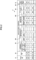
- FIG. 2 is a diagram illustrating an example of a data configuration of the actual result DB 6. Set as an individual set of actual result data is: measured values collected by the actual value collecting device 5, the measured values being values of predetermined manufacturing conditions and material properties; or estimated values estimated based on these measured values. Specifically, as illustrated in FIG.
- each set of actual result data is composed of manufacturing conditions 65 associated with a combination of a product number 61 and a mesh number 63, and a material-property-value 67.
- the product number 61 is an identification number for identifying that steel-strip product
- the mesh number 63 indicates a position in the steel-strip product corresponding to a target of measurement of measured values corresponding thereto (see FIG. 3 described later).
- the manufacturing conditions 65 are composed of values per manufacturing condition item, and in this embodiment, include a chemical composition 651, a thickness and width history 653, a temperature history 655, and a speed history 657.
- a chemical composition 651 measured values of the chemical composition per component are set as a component 1, a component 2, and so on. Types of components differ depending on the steel-strip products, and representative examples include carbon (C), manganese (Mn), silicon (Si), and aluminum (Al).
- C carbon
- Mn manganese
- Si silicon
- Al aluminum
- measured values of the slab thickness, the thickness between stands, the finishing thickness, and the like are set as a thickness 1, a thickness 2, and so on
- measured values of the width between stands, the finishing width, and the like are set as a width 1, and so on.
- measured values or estimated values of the delivery temperature of reheating process, the entry temperature of cooling process, the temperature during cooling, the temperature after cooling, and the like are set as a temperature 1, a temperature 2, and so on.
- measured values of the conveyance speed upon reheating, the conveyance speed upon rolling, the conveyance speed upon cooling, and the like are set as a speed 1, a speed 2, and so on.
- a measured value or an estimated value thereof is set.
- the actual result data registration process will be described.
- the actual value collecting device 5 collects measured values measured at any time by the measuring devices in the respective processes 10 to 14 in the manufacturing process thereof (collecting step).
- FIG. 3 is a diagram illustrating a target steel-strip product S2 that has finished being manufactured.
- a total length thereof is a length corresponding to a coiling amount
- the uncoiled target steel-strip product S2 has a strip shape with a thickness of the finishing thickness and a width of the finishing width.
- a length direction of the target steel-strip product S2 will be defined as an X-direction, a thickness direction thereof as a Y-direction, and a width direction thereof as a Z-direction.
- a measurement position tracking means include: a method of identifying, based on the number of times a walking beam is moved, a measurement position, the walking beam conveying the target material in the heating furnace in the reheating process 12; a method of detecting a measurement position by using y rays in the rolling process 13; a method of estimating, based on the number of rotations of a rolling mill in the rolling process 13, a measurement position; and a method of estimating a measurement position by counting the number of rotations of the coiler in the cooling process 14.
- the measured values of the thickness between stands, the finishing thickness, the width between stands, the finishing width, the delivery temperature of reheating process, the entry temperature of cooling process, the temperature during cooling, the temperature after cooling, the conveyance speed upon reheating, the conveyance speed upon rolling, and the conveyance speed upon cooling, which are measured in the respective processes 12 to 14, are ultimately collected for each of measurement positions corresponding to respective meshes of the meshed top layer illustrated in FIG. 3 , for example.
- An X-direction width of this mesh corresponds to a measurement period of the measuring devices in the respective processes 12 to 14.
- the actual value collecting device 5 divides the target steel-strip product S2 in the Y-direction also as illustrated in FIG. 3 , and allocates unique mesh numbers to all of the meshes.
- mesh numbers allocated to some of the meshes are illustrated as an example.
- the size of the meshes is not particularly limited, may be a size corresponding to the above mentioned measurement period, and is, for example, a size resulting from division in each of the X-direction, the Y-direction, and the Z-direction by a width in a range of, for example, from several tens of micrometers to several meters.
- the mesh number is allocated as, for example, a character string, which is a combination of a layer number and a serial number consecutively numbering each mesh, with an underbar, "-", interposed therebetween.
- the layer number is for identifying a position of a layer of each mesh.
- FIG. 3 meshes of four layers resulting from division into four in the Y-direction are illustrated, and their layer numbers in order from the top layer are "P1", "P2", “P3", and "P4".
- the Y-direction is not necessarily divided, and if the finishing thickness of the target steel-strip product is small, the meshes may be singly layered.
- the actual value collecting device 5 associates the values of the manufacturing condition items including the measured values by the measuring devices in the respective processes 12 to 14 with each of the meshes, into which the target steel-strip product S2 is divided as described above, to form one set of actual result data, and registers the one set of actual result data into the actual result DB 6.
- the chemical composition per component, of the values of the manufacturing condition items of each mesh is, for example, uniformly the measured values measured by the component measuring device 101.
- the slab thickness is, for example, the measured values measured by the thickness meter 111 for all of the meshes.
- the values of the thickness between stands, the finishing thickness, the width between stands, the finishing width, the delivery temperature of reheating process, the entry temperature of cooling process, the temperature during cooling, the temperature after cooling, the conveyance speed upon reheating, the conveyance speed upon rolling, and the conveyance speed upon cooling, the values for the meshes of the top layer having the layer number, "P1", are the measured values at the corresponding measurement positions obtained while tracking is being performed, as described above.
- Such values for meshes of the lower layers with the layer numbers, "P2", “P3”, and “P4", are the same values as the measured values of the respective meshes of the top layer, or estimated values estimated from these measured values.
- the values of the thickness between stands, the finishing thickness, the width between stands, the finishing width, the conveyance speed upon reheating, the conveyance speed upon rolling, and the conveyance speed upon cooling are the measured values for the meshes of the top layer with the same X-direction and X-direction positions.
- the values of the delivery temperature of reheating process, the entry temperature of cooling process, the temperature during cooling, and the temperature after cooling are, for example, estimated values obtained as a result of performing a process of estimating respective values of the delivery temperature of reheating process, the entry temperature of cooling process, the temperature during cooling, and the temperature after cooling at positions of the respective meshes of the lower layers by use of a heat transfer model or the like defined in advance based on the measured values of the respective meshes of the top layer.
- FIG. 4 is a flow chart illustrating a procedure of the material-property-value estimating process executed by the arithmetic processing unit 20 in the apparatus main body 2.
- the material-property-value estimating apparatus 1 the material-property-value estimating method is implemented, by the actual value collecting device 5 executing the above described actual result data registration process and the arithmetic processing unit 20 executing the material-property-value estimating process according to the procedure in FIG. 4 .
- the material-property-value estimating process may be realized by the arithmetic processing unit 20 reading and executing the property estimating program 31 stored in the ROM 30. This material-property-value estimating process is started when the coiler starts coiling up the target steel-strip product.
- the arithmetic processing unit 20 determines presence or absence of a mesh that has finished being manufactured by being newly coiled up by the coiler. If a mesh that has finished being manufactured is present, that is, every time an amount worth an X-direction width of a mesh is coiled up by the coiler (Step a1; Yes), the arithmetic processing unit 20 executes a process of a loop A for all of meshes that have finished being manufactured in order, the meshes being target meshes (Step a3 to Step a13).
- the steel-strip product manufactured by the manufacturing process 100 is long with a total length thereof being about 1000 meters, and the steel-strip product is coiled up by the coiler from a distal end side that has finished being manufactured first (for which up to the cooling process 14 has been completed); for a while after the coiling by the coiler is started, a portion that has been coiled up as a coil after finishing being manufactured and a portion in the middle of manufacturing (for which up to the cooling process 14 has not been completed) coexist with each other.
- the process of the loop A is executed for each of sixteen meshes at the right end, the sixteen meshes sequentially being the target meshes.
- the manufacturing condition obtaining unit 21 reads and obtains actual result data (hereinafter, referred to as "target actual result data") of a target mesh from the actual result DB 6, based on a product number of the target steel-strip product and a mesh number of the target mesh (Step a5).
- the property estimating unit 23 estimates a material-property-value of the target mesh by executing the processing of Step a7 to Step a11 (estimating step). That is, the property estimating unit 23 first sequentially reads the actual result data (hereinafter, referred to as "past actual result data") for each mesh related to steel-strip products manufactured in the past from the actual result DB 6, and calculates similarity between the respective data of the target actual result data and the past actual result data by comparing the values for each manufacturing condition item between the read actual result data and the target actual result data obtained in Step a5 (Step a7).
- past actual result data the actual result data for each mesh related to steel-strip products manufactured in the past from the actual result DB 6
- the property estimating unit 23 sequentially calculates, as the similarity to the corresponding past actual result data, a sum of squares of differences between values, each of the differences being a difference between values of the target actual result data and the past actual result data for each manufacturing condition item.
- the similarity is calculated as a higher value when the past actual result data have values per manufacturing condition item that are similar, as a whole, to the target actual result data and thus manufacturing conditions similar to the target mesh, and as a lower value for the other past actual result data.
- Similarity ⁇ 11 ⁇ Value of component 1 of target actual result data ⁇ Value of component 1 of past actual result data 2 + ⁇ 12 ⁇ Value of component 2 of target actual result data ⁇ Value of component 2 of past actual result data 2 ⁇ + ⁇ 21 ⁇ Value of thickness 1 of target actual result data ⁇ Value of thickness 1 of past actual result data 2 ⁇ + ⁇ 31 ⁇ Value of width 1 of target actual result data ⁇ Value of width 1 of past actual result data 2 ⁇ + ⁇ 41 ⁇ Value of temperature 1 of target actual result data ⁇ Value of temperature 1 of past actual result data 2 ⁇
- Equation (1) The equation for calculating the similarity expressed by the above Equation (1) is just an example, and is not limited to this example. That is, the equation for calculating the similarity is any equation expressing that the more similar the manufacturing conditions of the past actual result data are to those of the target mesh, the larger the numerical value becomes.
- the similarity to the target actual result data is calculated for all of the past actual result data registered in the actual result DB 6.
- actual result data of mesh numbers having the same layer number may be elected, and similarities may be calculated for the elected actual result data.
- the material-property-value is able to be estimated by retrieving the one which is higher in the similarity from manufacturing conditions of the same layer.
- the property estimating unit 23 retrieves, based on the similarities calculated in Step a7, past actual result data having the minimum similarity from the past actual result data (Step a9).
- the property estimating unit 23 estimates a material-property-value of the target mesh to be the material-property-value of the retrieved past actual result data, and updates the actual result data of the target mesh (Step a11).
- the process of the loop A for the target mesh is ended.
- the material-property-value estimating apparatus 1 functions as a registration means.
- a steel piece is sampled from the target steel-strip product manufactured, a material-property-value thereof is measured, and the measured value is output to the actual value collecting device 5 in the testing process 15 after the cooling process 14, and in this case, the actual value collecting device 5 updates the material-property-value of the mesh that the sampling position of the steel piece belongs, with the measured value.
- a technique used in the estimation of the material properties of the target meshes is not limited to the above described technique of using similarity.
- material properties of target meshes may be estimated from past actual result data by use of another technique, such as regression or interpolation.
- the visualizing unit 25 executes a process of generating a material-property-value image representing a distribution state of material properties in the target steel-strip product for each mesh layer and displaying the material-property-value image on the display device 4 (Step a17).
- the visualizing unit 25 reads the material-property-value of each mesh of the target steel-strip product per layer from the actual result DB 6, and executes the process of generating and displaying, as the material-property-value image, a contour graph for each layer, the contour graph depicting meshes with the same material-property-value value in the same color.
- FIG. 5 is a diagram illustrating an example of the material-property-value image, and illustrates a material-property-value image of the top layer with the layer number P1, with a horizontal direction thereof being a length direction of the target steel-strip product and a vertical direction thereof being a width direction of the target steel-strip product.
- the material-property-value images of the respective layers, the material-property-value images representing the distribution states of the material properties in the target steel-strip product as illustrated in FIG. 5 are displayed on the display device 4 side by side, or according to input of operation by an operator, a material-property-value image of one of the layers is selectively displayed and presented to the operator.
- the cut-off position determining unit 27 determines a cut-off position of the target steel-strip product (Step a19). Specifically, the cut-off position determining unit 27 firstly performs threshold processing of the property value of each mesh of the target steel-strip product by using, as a threshold, a permissible value of material-property-value defined according to required quality in advance, and distinguishes between a qualified portion where the material properties are not less than a threshold, and a disqualified portion. The cut-off position determining unit 27 then determines a boundary between the distinguished qualified portion and disqualified portion as the cut-off position.
- the cut-off position determining unit 27 transmits information related to the determined cut-off position to a steel-strip cutting device 152 in the testing process 15.
- the steel-strip cutting device 152 uncoils the steel-strip arranged at an uncoiler 153 up to the cut-off position by use of the uncoiler 153.
- the steel-strip cutting device 152 cuts the steel-strip at the cut-off position by transmitting a cut-off order command to a cutter 154.
- a manufacturing condition determining unit 28 determines manufacturing conditions of a steel-strip product planned to be manufactured subsequently to the target steel-strip product (Step a20: manufacturing condition determining step). Specifically, by using the property estimating unit 23 as an inversion calculation unit to calculate manufacturing conditions from a given material-property-value, the manufacturing condition determining unit 28 calculates manufacturing conditions, by which the material properties match required specifications, and adds a difference between the calculated manufacturing conditions and the set manufacturing conditions, as a set correction term of the manufacturing conditions of the steel-strip product planned to be manufactured next, to the manufacturing conditions.
- the manufacturing condition determining unit 28 estimates material properties of virtual steel-strip products of five types having new manufacturing conditions with coiling temperature being 500°C, 525°C, 550°C, 575°C, and 600°C.
- the numerical values of the coiling temperature may be other values.
- the manufacturing condition determining unit 28 selects the manufacturing condition with the coiling temperature of 525°C that is closest to the required specification.
- the specific method is not limited to this method.
- FIG. 6 is a diagram illustrating an example of the relations between the temperature after cooling and the material properties for different values of the temperature during cooling, T M1 , T M3 , and T M5 . As illustrated in FIG.
- the material properties are determined to be unsatisfactory even though the material properties are actually satisfactory.
- FIG. 7(a) is a diagram illustrating a temperature distribution of the measured temperature during cooling in the steel-strip product
- FIG. 7(b) is a diagram illustrating a temperature distribution of the measured temperature after cooling in the steel-strip product
- FIG. 7(c) is a diagram illustrating a material-property-value image of the steel-strip product, the material-property-value image obtained by the material-property-value estimating process.
- FIG. 7(b) boundaries (cut-off positions) L31 and L33 between a qualified portion and a disqualified portion in the steel-strip product are illustrated, the qualified portion and the disqualified portion determined according to results of the above described determination of quality of the material properties with the temperature after cooling being an index.
- FIG. 7(c) illustrates cut-off positions L35 and L37 obtained by the material-property-value estimating process.
- end portions including qualified portions R31 and R33 having satisfactory material properties are cut-off, and thus the yield is reduced.
- the cut-off may be done with a disqualified portion having unsatisfactory material properties being left behind. In this case, the required quality is unable to be achieved.
- measured values of factors influencing the material properties as described above are collected as manufacturing condition items, and the material properties are estimated by use of the collected measured values or estimated values estimated from the measured values.
- the chemical composition per component, the slab thickness, the thickness between stands, the finishing thickness, the width between stands, the finishing width, the delivery temperature of reheating process, the entry temperature of cooling process, the temperature during cooling, and the temperature after cooling are the manufacturing condition items.
- the measured values by the measuring devices in the reheating process 12, the rolling process 13, and the cooling process 14, which are performed while a target material is being conveyed, of the manufacturing process 100, are obtained while their measurement positions are being tracked.
- the material properties are then estimated per mesh corresponding to a measurement position of a measured value in the respective processes 12 to 14. Therefore, by performing threshold processing of the estimated material properties and distinguishing between a qualified portion and a disqualified portion in the steel-strip product, cut-off positions of the steel-strip product are able to be determined appropriately. Thereby, while the required quality is achieved, the decrease in the yield is able to be reduced.
- a manufacturing condition of a steel-strip product planned to be manufactured subsequently to the target steel-strip product is corrected. Therefore, the more similar the properties of the target steel-strip product are to those of the steel-strip product to be manufactured next, the more appropriately the correction is able to be performed, such that manufacturing conditions satisfying the required specification of the material-property-value are obtained. Thereby, the part satisfying the required quality is increased and the yield is able to be improved.
- a material-property-value estimating method and a material-property-value estimating apparatus which enable material properties of steel-strips to be estimated accurately are able to be provided. Further, a method of manufacturing a steel-strip, the method enabling decrease in yields to be reduced, is able to be provided.
Landscapes
- Engineering & Computer Science (AREA)
- Chemical & Material Sciences (AREA)
- Mechanical Engineering (AREA)
- Physics & Mathematics (AREA)
- Health & Medical Sciences (AREA)
- Life Sciences & Earth Sciences (AREA)
- Materials Engineering (AREA)
- Metallurgy (AREA)
- Organic Chemistry (AREA)
- General Health & Medical Sciences (AREA)
- General Physics & Mathematics (AREA)
- Pathology (AREA)
- Immunology (AREA)
- Analytical Chemistry (AREA)
- Biochemistry (AREA)
- Thermal Sciences (AREA)
- Crystallography & Structural Chemistry (AREA)
- Medicinal Chemistry (AREA)
- Food Science & Technology (AREA)
- Control Of Metal Rolling (AREA)
- Metal Rolling (AREA)
- General Factory Administration (AREA)
- Control Of Heat Treatment Processes (AREA)
Abstract
Description
- The present invention relates to a material-property-value estimating method and a material-property-value estimating apparatus for estimating material properties of a steel-strip, and to a method of manufacturing a steel-strip.
- Steel-strip products manufactured via processes including a reheating process, a forming process, and a cooling process are delivered to customers as coils, or sent to a subsequent process in order to be processed further. In order to guarantee the quality required (material properties including strength), quality assessment of such steel-strip products is performed before the delivery or the like. In general, since the quality of a steel-strip product is not stable at end portions thereof, the quality of the whole product is maintained by cut-off positions being determined from results of the quality assessment and the end portions being cut off.
- For example, as a technique for assessing the quality, a technique has been known, in which the temperature is measured by the entire area of a hot-rolled metal strip being imaged by a near infrared camera (thermography) and the quality is assessed based on the measured temperature distribution (see Patent Literature 1).
- Patent Literature 1: Japanese Laid-open Patent Publication No.
2008-296251 - However, since the above mentioned technique of
Patent Literature 1 focuses on a correlation between the quality (material-property-value) and the temperature of the hot-rolled metal strip, and the quality is assessed by use of the temperature as an index; influence of factors other than the temperature on the quality is unable to be considered, and accuracy of the quality assessment has been insufficient in some cases. Further, as a result, there has been a problem that the cut-off positions are unable to be determined appropriately, and thus the cut-off is performed with an inferior quality portion (an area with a disqualified material-property-value) being left behind, or on the contrary, even a satisfactory quality portion (an area with a qualified material-property-value) is also cut off and the yield is decreased. - The present invention has been made in view of the above, and object thereof is to provide a material-property-value estimating method and a material-property-value estimating apparatus, which enable material properties of a steel-strip to be estimated accurately. Further, another object of the present invention is to provide a method of manufacturing a steel-strip, the method enabling decrease in the yield to be reduced.
- To solve the problem and achieve the object, a material-property-value estimating method of estimating a material-property-value of a target steel-strip product manufactured via at least one of a reheating process, a rolling process, and a cooling process, which are performed while a target material is being conveyed along a conveyance route according to the present invention is a method of estimating a material-property-value of each of meshes dividing the target steel-strip product based on a measured value that has been measured once or more by a measuring device installed on the conveyance route, the measured value including at least a temperature of the target material; and a chemical composition per component of the target steel-strip product
- Moreover, a material-property-value estimating apparatus that estimates a material-property-value of a target steel-strip product manufactured via at least one of a reheating process, a rolling process, and a cooling process, which are performed while a target material is being conveyed along a conveyance route according to the present invention includes: an estimating means that estimates a material-property-value of each of meshes dividing the target steel-strip product, based on: a measured value that has been measured once or more by a measuring device installed on the conveyance route, the measured value including at least a temperature of the target material; and a chemical composition per component of the target steel-strip product.
- Moreover, a method of manufacturing a steel-strip manufactured via at least one of a reheating process, a rolling process, and a cooling process, which are performed while a target material is being conveyed along a conveyance route according to the present invention includes: an estimating step of estimating a material-property-value of each of meshes dividing the steel-strip based on: a measured value that has been measured once or more by a measuring device installed on the conveyance route, the measured value including at least a temperature of the target material; and a chemical composition per component of the steel-strip; and a cutting step of determining a boundary position between a qualified portion and a disqualified portion in the steel-strip by performing threshold processing of the estimated material-property-value of each of the meshes, and cutting the steel-strip at the determined boundary position.
- Moreover, a method of manufacturing a steel-strip manufactured via at least one of a reheating process, a rolling process, and a cooling process, which are performed while a target material is being conveyed along a conveyance route according to the present invention includes: an estimating step of estimating a material-property-value of each of meshes dividing the target steel-strip product based on: a measured value that has been measured once or more by a measuring device installed on the conveyance route, the measured value including at least a temperature of the target material; and a chemical composition per component of the target steel-strip product; and a manufacturing condition determining step of changing one or more settings of manufacturing conditions of the steel-strip, based on a difference between the estimated material-property-value of each of the meshes and a required specification of material-property-value. Advantageous Effects of Invention
- According to the present invention, material properties of a steel-strip are able to be estimated accurately. Further, according to the present invention, decrease in the yield of a steel-strip manufacturing process is able to be reduced.
-
-
FIG. 1 is a schematic diagram illustrating an example of an overall configuration of a material-property-value estimating apparatus, and a manufacturing process, to which this material-property-value estimating apparatus is applied. -
FIG. 2 is a diagram illustrating an example of a data configuration of an actual result database. -
FIG. 3 is a diagram illustrating a target steel-strip product. -
FIG. 4 is a flow chart illustrating a procedure of a material-property-value estimating process. -
FIG. 5 is a diagram illustrating an example of a material-property-value image. -
FIG. 6 is a diagram illustrating an example of relations between temperature after cooling and material properties under different temperatures during cooling. -
FIG. 7 is a diagram illustrating a temperature distribution of temperature during cooling (a), a temperate distribution of temperature after cooling (b), and a material-property-value image (c). - Hereinafter, with reference to the drawings, a mode for implementing a material-property-value estimating apparatus and a material-property-value estimating method of the present invention will be described. The present invention is not limited by this embodiment. Further, in the drawings, the same portions will be illustrated with the same signs appended thereto.
-
FIG. 1 is a schematic diagram illustrating an example of an overall configuration of a material-property-value estimatingapparatus 1 of this embodiment, and amanufacturing process 100, to which this material-property-value estimatingapparatus 1 is applied. - First of all, the
manufacturing process 100 will be described. As illustrated inFIG. 1 , themanufacturing process 100 includes: arefining process 10; acasting process 11; areheating process 12; arolling process 13 as a forming process; acooling process 14, and atesting process 15. Facilities for implementing thereheating process 12, therolling process 13, and thecooling process 14, of theserespective processes 10 to 15, are installed on a conveyance route of a target material (a slab S11 or a rolled material S13), the conveyance route formed by table rolls (not illustrated) being laid thereon; and carry out reheating, rolling, and cooling of the slab S11 or the rolled material S13 sequentially conveyed in a conveyance direction A1 on the conveyance route. - The
refining process 10 is a process of adjusting and adding weights of component elements (chemical composition) to steel in a liquid state, and thereby forming steel of a predetermined composition. In thisrefining process 10, acomponent measuring device 101 is installed, and the adjusted chemical composition (actual value) per component of steel is measured. The measured chemical composition per component is output at any time to an actualvalue collecting device 5 described later. - The
subsequent casting process 11 is a process of: cooling the steel in the liquid state, the steel having been adjusted to the above mentioned predetermined composition; casting the steel in a plate shape; and cutting the steel by a predetermined length into the slab S11. In thiscasting process 11, athickness meter 111 is installed, and thickness of the slab S11 (slab thickness) is measured. The measured slab thickness is output at any time to the actualvalue collecting device 5. - The
subsequent reheating process 12 is a process of reheating the slab S11 with aheating furnace 121 to near 1250°C. In thisreheating process 12, for example, athermometer 123 is installed at an outlet side of theheating furnace 121, and surface temperature (delivery temperature of reheating process) of the slab S11 at the time of completion of reheating when the installation location is passed is continuously measured. The measured delivery temperature of reheating process is output at any time to the actualvalue collecting device 5. - The
subsequent rolling process 13 is a process of stepwisely rolling the rolled material (the slab that has finished being reheated) S13 with pluralrolling mill rolls rolling mill rolls 131 constituting roughers and therolling mill rolls 132 constituting finishers; and the slab thickness of about 250 mm is rolled thinly to about 1 mm to 20 mm. In thisrolling process 13, as dimension meters, for example, a thickness andwidth meter 133 is installed in the middle of rolling, such as between the roughers and the finishers, and a thickness andwidth meter 135 is installed at an outlet side of the finishers. In thisrolling process 13, thickness (thickness between stands) and width (width between stands) of the rolled material S13 when the rolled material S13 passes the installation location of the thickness andwidth meter 133, and thickness (finishing thickness) and width (finishing width) of the rolled material S13 when the rolled material S13 passes the installation location of the thickness andwidth meter 135 are measured continuously. Further, in therolling process 13, for example, ameasuring roll 137, which is a speed meter, is installed in the middle of rolling, such as between the roughers and the finishers, and conveyance speed (conveyance speed upon rolling) of the rolled material S13 in therolling process 13 is continuously measured. The thickness between stands, the finishing thickness, the width between stands, the finishing width, and the conveyance speed upon rolling, which have been measured, are output at any time to the actualvalue collecting device 5. - The
subsequent cooling process 14 is a process of supplying cooling water to the rolled material S13 that has finished being rolled, and cooling the rolled material S13 to several hundred degrees Celsius, by use ofplural coolants 141. In thiscooling process 14, for example, athermometer 143 is installed at an inlet side of the mostupstream coolant 141, athermometer 145 is installed in the middle of cooling between thecoolants 141, and athermometer 147 is installed at an outlet side of the mostdownstream coolant 141. In thiscooling process 14, surface temperature (entry temperature of cooling process) of the rolled material S13 passing thethermometer 143, surface temperature (temperature during cooling) of the rolled material S13 passing thethermometer 145, and surface temperature (temperature after cooling) of the rolled material S13 passing thethermometer 147 are measured continuously. Further, in thecooling process 14, a tachometer (not illustrated) as a speed meter is installed at an appropriate location, such as in the middle of cooling, and conveyance speed of the rolled material S13 in the cooling process 14 (conveyance speed upon cooling) is continuously measured by the number of rotations of the table rolls being measured and converted into speed. The entry temperature of cooling process, the temperature during cooling, the temperature after cooling, and the conveyance speed upon cooling, which have been measured, are output at any time to the actualvalue collecting device 5. - A steel-strip product that has been manufactured by finishing being subjected up to the
cooling process 14 as described above is coiled up by a coiler (not illustrated) into a coil S15. Thesubsequent testing process 15 is a process of performing a tension test on a steel piece (test piece) S17 sampled from an end portion or the like of the steel-strip product (coil) S15 by uncoiling the steel-strip product (coil) S15; and yield strength (YS), tension strength (TS), and elongation (EL) of the steel piece S17 are measured by atester 151. The respective values of the yield strength YS, the tension strength TS, and the elongation EL, which have been measured, are output at any time as material properties (actual values), together with a sampling position of the steel piece S17 in the steel-strip product S15, to the actualvalue collecting device 5. - The number of installed thermometers and their installation locations in the
reheating process 12 and thecooling process 14 are not limited to the above described number of installed thermometers and the installation locations, and at least one thermometer is preferably installed in each of therespective processes rolling process 13 are similarly not limited to the number of installed thickness and width meters and their installation locations described above, and at least one thickness and width meter is preferably installed. However, in order to accurately estimate material properties described later, all of temperatures of the rolled material S3 before cooling, in the middle of cooling, and at the time of completion of cooling in the cooling process 14 (the entry temperature of cooling process, the temperature during cooling, and the temperature after cooling) are desirably obtained. Further, the rolled material processed in the processes from theheating furnace 121 to the coiler S15 is not limited to a single rolled material as described above, and plural rolled materials may be processed. - Further, the measurement of temperature of the slab S11 or the rolled material S13 by the
thermometer thickness meter 111 or the thickness andwidth meter - The material-property-
value estimating apparatus 1 applied to thismanufacturing process 100 is configured by: an apparatusmain body 2, aninput device 3, adisplay device 4, the actualvalue collecting device 5 serving as a collecting means, and anactual result DB 6 serving as an actual result data storage means, being connected to one another to be able to transmit and receive data via atransmission bus 7 and abus wiring 50 that connects between respective units in the apparatusmain body 2. - The apparatus
main body 2 is realized by use of a general-purpose information processing device, such as a personal computer or a work station, and includes anarithmetic processing unit 20, a ROM 30, and aRAM 40. - The
arithmetic processing unit 20 is realized by hardware, such as a CPU. Thisarithmetic processing unit 20 integrally controls operation of the whole material-property-value estimating apparatus 1 by performing instruction, data transfer, and the like to the respective units constituting the material-property-value estimating apparatus 1; based on programs and data stored in the ROM 30, operation signals input from theinput device 3, various types of information and the like obtained from the actualvalue collecting device 5 and theactual result DB 6. Thisarithmetic processing unit 20 includes, as main functional units, a manufacturingcondition obtaining unit 21, aproperty estimating unit 23 serving as an estimating means, a visualizingunit 25 serving as a display processing means, and a cut-offposition determining unit 27 serving as a determining means. - In the ROM 30: programs for causing the material-property-
value estimating apparatus 1 to operate and realizing various functions that this material-property-value estimating apparatus 1 includes; data used during execution of these programs; and the like, are stored. Further, aproperty estimating program 31 is stored therein, the property estimating program 31: causing thearithmetic processing unit 20 to function as the manufacturingcondition obtaining unit 21, theproperty estimating unit 23, the visualizingunit 25, and the cut-offposition determining unit 27; and visualizing material properties of the steel-strip product S15 after estimating the material properties. - The
RAM 40 is a semiconductor memory used as a working memory of thearithmetic processing unit 20; and includes a memory space that temporarily holds therein the programs executed by thearithmetic processing unit 20, data used during execution thereof, and the like. - The
input device 3 is realized by an input device, such as, for example, a keyboard and a mouse, a touch panel, or various switches; and outputs input signals according to input of operation to the apparatusmain body 2. Thedisplay device 4 is realized by a display device, such as an LCD, an EL display, or a CRT display; and displays thereon various screens based on display signals input from the apparatusmain body 2. - The actual
value collecting device 5 may be realized by a known hardware configuration including: an arithmetic unit, such as a CPU; a main storage device; an auxiliary storage device, such as a hard disk or any of various storage media; a communication device; a display device; an input device; and the like, and for example, a general-purpose computer, such as a server computer, a work station, or a personal computer, may be used as the actualvalue collecting device 5. This actualvalue collecting device 5 is connected, via thetransmission bus 7, to the measuring devices in themanufacturing process 100, such as thecomponent measuring device 101 of therefining process 10, thethickness meter 111 of thecasting process 11, thethermometer 123 of thereheating process 12, the thickness andwidth meters roll 137 of the rollingprocess 13, thethermometers cooling process 14, and thetester 151 of thetesting process 15, which have been described above. The actualvalue collecting device 5 collects measured values of: the chemical composition per component; the slab thickness; the thickness between stands; the finishing thickness; the width between stands; the finishing width; the delivery temperature of reheating process; the entry temperature of cooling process; the temperature during cooling; the temperature after cooling; the conveyance speed upon reheating; the conveyance speed upon rolling; the conveyance speed upon cooling; and the material properties, which have been measured by these measuring devices; and performs, based on the collected measured values, a process of registering actual result data of the steel-strip product S15 sequentially manufactured in themanufacturing process 100 into the actual result DB 6 (actual result data registration process). - The
actual result DB 6 is a database (DB) accumulating therein actual result data of steel-strip products manufactured in the past by themanufacturing process 100, and is constructed by actual result data being registered and updated every time the steel-strip product S15 is manufactured by the manufacturing process 100 (storage step).FIG. 2 is a diagram illustrating an example of a data configuration of theactual result DB 6. Set as an individual set of actual result data is: measured values collected by the actualvalue collecting device 5, the measured values being values of predetermined manufacturing conditions and material properties; or estimated values estimated based on these measured values. Specifically, as illustrated inFIG. 2 , each set of actual result data is composed ofmanufacturing conditions 65 associated with a combination of aproduct number 61 and amesh number 63, and a material-property-value 67. Theproduct number 61 is an identification number for identifying that steel-strip product, and themesh number 63 indicates a position in the steel-strip product corresponding to a target of measurement of measured values corresponding thereto (seeFIG. 3 described later). - The
manufacturing conditions 65 are composed of values per manufacturing condition item, and in this embodiment, include achemical composition 651, a thickness andwidth history 653, atemperature history 655, and aspeed history 657. In thechemical composition 651, measured values of the chemical composition per component are set as acomponent 1, acomponent 2, and so on. Types of components differ depending on the steel-strip products, and representative examples include carbon (C), manganese (Mn), silicon (Si), and aluminum (Al). In the thickness andwidth history 653, measured values of the slab thickness, the thickness between stands, the finishing thickness, and the like are set as athickness 1, athickness 2, and so on, and measured values of the width between stands, the finishing width, and the like are set as awidth 1, and so on. In thetemperature history 655, measured values or estimated values of the delivery temperature of reheating process, the entry temperature of cooling process, the temperature during cooling, the temperature after cooling, and the like are set as atemperature 1, atemperature 2, and so on. In thespeed history 657, measured values of the conveyance speed upon reheating, the conveyance speed upon rolling, the conveyance speed upon cooling, and the like are set as aspeed 1, aspeed 2, and so on. In the material-property-value, a measured value or an estimated value thereof is set. - Next, flows of processes performed in the material-property-
value estimating apparatus 1 configured as described above will be described. First, the actual result data registration process will be described. In this actual result data registration process, from when manufacturing of a steel-strip product (target steel-strip product) manufactured at that time is started to when the manufacturing is finished, the actualvalue collecting device 5 collects measured values measured at any time by the measuring devices in therespective processes 10 to 14 in the manufacturing process thereof (collecting step). -
FIG. 3 is a diagram illustrating a target steel-strip product S2 that has finished being manufactured. As illustrated inFIG. 3 , when the target steel-strip product S2 that has finished being manufactured is uncoiled from a coiled state, a total length thereof is a length corresponding to a coiling amount, and the uncoiled target steel-strip product S2 has a strip shape with a thickness of the finishing thickness and a width of the finishing width. Hereinafter, a length direction of the target steel-strip product S2 will be defined as an X-direction, a thickness direction thereof as a Y-direction, and a width direction thereof as a Z-direction. - Of the
manufacturing process 100, in thereheating process 12, the rollingprocess 13, and thecooling process 14, which are performed while the target material is being conveyed, measured values by the measuring devices in therespective processes 12 to 14 are obtained while measurement positions thereof are being tracked. Examples of a measurement position tracking means include: a method of identifying, based on the number of times a walking beam is moved, a measurement position, the walking beam conveying the target material in the heating furnace in thereheating process 12; a method of detecting a measurement position by using y rays in the rollingprocess 13; a method of estimating, based on the number of rotations of a rolling mill in the rollingprocess 13, a measurement position; and a method of estimating a measurement position by counting the number of rotations of the coiler in thecooling process 14. As a result, the measured values of the thickness between stands, the finishing thickness, the width between stands, the finishing width, the delivery temperature of reheating process, the entry temperature of cooling process, the temperature during cooling, the temperature after cooling, the conveyance speed upon reheating, the conveyance speed upon rolling, and the conveyance speed upon cooling, which are measured in therespective processes 12 to 14, are ultimately collected for each of measurement positions corresponding to respective meshes of the meshed top layer illustrated inFIG. 3 , for example. An X-direction width of this mesh corresponds to a measurement period of the measuring devices in therespective processes 12 to 14. - In the actual result data registration process, the actual
value collecting device 5 divides the target steel-strip product S2 in the Y-direction also as illustrated inFIG. 3 , and allocates unique mesh numbers to all of the meshes. InFIG. 3 , mesh numbers allocated to some of the meshes are illustrated as an example. The size of the meshes is not particularly limited, may be a size corresponding to the above mentioned measurement period, and is, for example, a size resulting from division in each of the X-direction, the Y-direction, and the Z-direction by a width in a range of, for example, from several tens of micrometers to several meters. - The mesh number is allocated as, for example, a character string, which is a combination of a layer number and a serial number consecutively numbering each mesh, with an underbar, "-", interposed therebetween. The layer number is for identifying a position of a layer of each mesh. In
FIG. 3 , meshes of four layers resulting from division into four in the Y-direction are illustrated, and their layer numbers in order from the top layer are "P1", "P2", "P3", and "P4". The Y-direction is not necessarily divided, and if the finishing thickness of the target steel-strip product is small, the meshes may be singly layered. - The actual
value collecting device 5 associates the values of the manufacturing condition items including the measured values by the measuring devices in therespective processes 12 to 14 with each of the meshes, into which the target steel-strip product S2 is divided as described above, to form one set of actual result data, and registers the one set of actual result data into theactual result DB 6. - When explanation is made in order, the chemical composition per component, of the values of the manufacturing condition items of each mesh, is, for example, uniformly the measured values measured by the
component measuring device 101. Similarly, the slab thickness is, for example, the measured values measured by thethickness meter 111 for all of the meshes. - Further, the values of the thickness between stands, the finishing thickness, the width between stands, the finishing width, the delivery temperature of reheating process, the entry temperature of cooling process, the temperature during cooling, the temperature after cooling, the conveyance speed upon reheating, the conveyance speed upon rolling, and the conveyance speed upon cooling, the values for the meshes of the top layer having the layer number, "P1", are the measured values at the corresponding measurement positions obtained while tracking is being performed, as described above. Such values for meshes of the lower layers with the layer numbers, "P2", "P3", and "P4", are the same values as the measured values of the respective meshes of the top layer, or estimated values estimated from these measured values. Specifically, the values of the thickness between stands, the finishing thickness, the width between stands, the finishing width, the conveyance speed upon reheating, the conveyance speed upon rolling, and the conveyance speed upon cooling are the measured values for the meshes of the top layer with the same X-direction and X-direction positions. Further, the values of the delivery temperature of reheating process, the entry temperature of cooling process, the temperature during cooling, and the temperature after cooling are, for example, estimated values obtained as a result of performing a process of estimating respective values of the delivery temperature of reheating process, the entry temperature of cooling process, the temperature during cooling, and the temperature after cooling at positions of the respective meshes of the lower layers by use of a heat transfer model or the like defined in advance based on the measured values of the respective meshes of the top layer.
- Since the material properties are estimated by a material-property-value estimating process described later (Step all in
FIG. 4 ) or measured in thetesting process 15 of the later stage, values thereof are not set herein. - Next, the material-property-value estimating process will be described.
FIG. 4 is a flow chart illustrating a procedure of the material-property-value estimating process executed by thearithmetic processing unit 20 in the apparatusmain body 2. In the material-property-value estimating apparatus 1, the material-property-value estimating method is implemented, by the actualvalue collecting device 5 executing the above described actual result data registration process and thearithmetic processing unit 20 executing the material-property-value estimating process according to the procedure inFIG. 4 . The material-property-value estimating process may be realized by thearithmetic processing unit 20 reading and executing theproperty estimating program 31 stored in the ROM 30. This material-property-value estimating process is started when the coiler starts coiling up the target steel-strip product. - That is, the
arithmetic processing unit 20 determines presence or absence of a mesh that has finished being manufactured by being newly coiled up by the coiler. If a mesh that has finished being manufactured is present, that is, every time an amount worth an X-direction width of a mesh is coiled up by the coiler (Step a1; Yes), thearithmetic processing unit 20 executes a process of a loop A for all of meshes that have finished being manufactured in order, the meshes being target meshes (Step a3 to Step a13). Since the steel-strip product manufactured by themanufacturing process 100 is long with a total length thereof being about 1000 meters, and the steel-strip product is coiled up by the coiler from a distal end side that has finished being manufactured first (for which up to thecooling process 14 has been completed); for a while after the coiling by the coiler is started, a portion that has been coiled up as a coil after finishing being manufactured and a portion in the middle of manufacturing (for which up to thecooling process 14 has not been completed) coexist with each other. - For example, when a distal end of the target steel-strip product illustrated in
FIG. 3 has started to be coiled up by the coiler and an amount worth an X-direction width of a mesh has been coiled up, the process of the loop A is executed for each of sixteen meshes at the right end, the sixteen meshes sequentially being the target meshes. - That is, in the loop A, first, the manufacturing
condition obtaining unit 21 reads and obtains actual result data (hereinafter, referred to as "target actual result data") of a target mesh from theactual result DB 6, based on a product number of the target steel-strip product and a mesh number of the target mesh (Step a5). - Subsequently, the
property estimating unit 23 estimates a material-property-value of the target mesh by executing the processing of Step a7 to Step a11 (estimating step). That is, theproperty estimating unit 23 first sequentially reads the actual result data (hereinafter, referred to as "past actual result data") for each mesh related to steel-strip products manufactured in the past from theactual result DB 6, and calculates similarity between the respective data of the target actual result data and the past actual result data by comparing the values for each manufacturing condition item between the read actual result data and the target actual result data obtained in Step a5 (Step a7). For example, according to the following Equation (1), theproperty estimating unit 23 sequentially calculates, as the similarity to the corresponding past actual result data, a sum of squares of differences between values, each of the differences being a difference between values of the target actual result data and the past actual result data for each manufacturing condition item. By this process, the similarity is calculated as a higher value when the past actual result data have values per manufacturing condition item that are similar, as a whole, to the target actual result data and thus manufacturing conditions similar to the target mesh, and as a lower value for the other past actual result data.
- The equation for calculating the similarity expressed by the above Equation (1) is just an example, and is not limited to this example. That is, the equation for calculating the similarity is any equation expressing that the more similar the manufacturing conditions of the past actual result data are to those of the target mesh, the larger the numerical value becomes.
- Further, herein, the similarity to the target actual result data is calculated for all of the past actual result data registered in the
actual result DB 6. On the contrary, based on a mesh number of the target actual result data, actual result data of mesh numbers having the same layer number may be elected, and similarities may be calculated for the elected actual result data. Thereby, the material-property-value is able to be estimated by retrieving the one which is higher in the similarity from manufacturing conditions of the same layer. - Thereafter, the
property estimating unit 23 retrieves, based on the similarities calculated in Step a7, past actual result data having the minimum similarity from the past actual result data (Step a9). Theproperty estimating unit 23 then estimates a material-property-value of the target mesh to be the material-property-value of the retrieved past actual result data, and updates the actual result data of the target mesh (Step a11). Thereafter, the process of the loop A for the target mesh is ended. By this process and the above described actual result data registration process, the material-property-value estimating apparatus 1 functions as a registration means. - As described above, a steel piece is sampled from the target steel-strip product manufactured, a material-property-value thereof is measured, and the measured value is output to the actual
value collecting device 5 in thetesting process 15 after thecooling process 14, and in this case, the actualvalue collecting device 5 updates the material-property-value of the mesh that the sampling position of the steel piece belongs, with the measured value. - Further, a technique used in the estimation of the material properties of the target meshes is not limited to the above described technique of using similarity. For example, material properties of target meshes may be estimated from past actual result data by use of another technique, such as regression or interpolation.
- When the coiler has finished coiling up the target steel-strip product and the process of loop A has been executed for all of the meshes (Step a15; Yes), subsequently, the visualizing
unit 25 executes a process of generating a material-property-value image representing a distribution state of material properties in the target steel-strip product for each mesh layer and displaying the material-property-value image on the display device 4 (Step a17). For example, the visualizingunit 25 reads the material-property-value of each mesh of the target steel-strip product per layer from theactual result DB 6, and executes the process of generating and displaying, as the material-property-value image, a contour graph for each layer, the contour graph depicting meshes with the same material-property-value value in the same color. -
FIG. 5 is a diagram illustrating an example of the material-property-value image, and illustrates a material-property-value image of the top layer with the layer number P1, with a horizontal direction thereof being a length direction of the target steel-strip product and a vertical direction thereof being a width direction of the target steel-strip product. At Step a17 inFIG. 4 , the material-property-value images of the respective layers, the material-property-value images representing the distribution states of the material properties in the target steel-strip product as illustrated inFIG. 5 , are displayed on thedisplay device 4 side by side, or according to input of operation by an operator, a material-property-value image of one of the layers is selectively displayed and presented to the operator. - Subsequently, the cut-off
position determining unit 27 determines a cut-off position of the target steel-strip product (Step a19). Specifically, the cut-offposition determining unit 27 firstly performs threshold processing of the property value of each mesh of the target steel-strip product by using, as a threshold, a permissible value of material-property-value defined according to required quality in advance, and distinguishes between a qualified portion where the material properties are not less than a threshold, and a disqualified portion. The cut-offposition determining unit 27 then determines a boundary between the distinguished qualified portion and disqualified portion as the cut-off position. The cut-offposition determining unit 27 transmits information related to the determined cut-off position to a steel-strip cutting device 152 in thetesting process 15. The steel-strip cutting device 152 uncoils the steel-strip arranged at anuncoiler 153 up to the cut-off position by use of theuncoiler 153. The steel-strip cutting device 152 cuts the steel-strip at the cut-off position by transmitting a cut-off order command to a cutter 154. - Subsequently, a manufacturing
condition determining unit 28 determines manufacturing conditions of a steel-strip product planned to be manufactured subsequently to the target steel-strip product (Step a20: manufacturing condition determining step). Specifically, by using theproperty estimating unit 23 as an inversion calculation unit to calculate manufacturing conditions from a given material-property-value, the manufacturingcondition determining unit 28 calculates manufacturing conditions, by which the material properties match required specifications, and adds a difference between the calculated manufacturing conditions and the set manufacturing conditions, as a set correction term of the manufacturing conditions of the steel-strip product planned to be manufactured next, to the manufacturing conditions. For example, if coiling temperature is one of manufacturing conditions in a cooling process, and a coiling temperature in a representative mesh of a steel-strip is 550°C, the manufacturingcondition determining unit 28 estimates material properties of virtual steel-strip products of five types having new manufacturing conditions with coiling temperature being 500°C, 525°C, 550°C, 575°C, and 600°C. The numerical values of the coiling temperature may be other values. - If tension strengths, which are the estimated material properties, are respectively 600 MPa, 620 MPa, 600 MPa, 580 MPa, and 560 MPa, and the required specification is 620 MPa, the manufacturing
condition determining unit 28 selects the manufacturing condition with the coiling temperature of 525°C that is closest to the required specification. Next, since the coiling temperature of the steel-strip product is 550°C, and the coiling temperature closest to the required specification is 525°C, if the coiling temperature for a steel-strip product to be manufactured next has been set at 560°C, the manufacturingcondition determining unit 28 calculates the correction amount to be 525°C - 550 = -25°C and sets the coiling temperature of the steel-strip product planned to be manufactured next to 560°C - 25°C = 535°C. In this embodiment, as a specific method of configuring an inversion calculation method, the method, in which the material-property-value closest to the required specification is retrieved from the plural manufacturing conditions around the manufacturing condition, has been described, but practically, the specific method is not limited to this method. - Next, effects of this embodiment will be described. For that, firstly, focusing on a case where temperature during cooling measured in the
manufacturing process 100 differs, relations between the temperature after cooling and the material properties will be described.FIG. 6 is a diagram illustrating an example of the relations between the temperature after cooling and the material properties for different values of the temperature during cooling, TM1, TM3, and TM5. As illustrated inFIG. 6 , the relations between the temperature after cooling and the material properties indicate a trend, for all of the temperatures during cooling = TM1, TM3, and TM5, that the higher the temperature after cooling is, the lower the material-property-value is, but overall, when the temperature during cooling = TM1, the material-property-value is large, and in order of the temperatures during cooling = TM3 and TM5, the material properties become smaller. - A case will now be considered, where quality of material properties is determined, by defining, from a correlation between the values of the temperature after cooling and the material properties, a temperature after cooling, TR5, which satisfies a permissible value of material-property-value (required quality) and performing threshold processing of the temperature after cooling. In this case, the material-property-value will be determined as satisfactory if the temperature after cooling is not higher than TR5, and as unsatisfactory if the temperature after cooling is higher than TR5. However, actually, as illustrated in
FIG. 6 , the temperature during cooling also affects the material properties, and when the temperature during cooling = TM5, if the temperature after cooling is higher than TR5, the material-property-value is unsatisfactory. On the contrary, when the temperature during cooling = TM3, even if the temperature after cooling is higher than TR5, the material-property-value is satisfactory up to TR3. When the temperature during cooling = TM1, the material-property-value is satisfactory up to an even higher temperature after cooling of TR1. - As described above, in determining quality of material properties by using the temperature after cooling as an index, without considering the temperature during cooling; when the temperature during cooling = TM3 and the temperature after cooling is TR5 to TR3, or when the temperature during cooling =TM1 and the temperature after cooling is TR5 to TR1, the material properties are determined to be unsatisfactory even though the material properties are actually satisfactory.
- For comparison, the material-property-value estimating process illustrated in
FIG. 4 was further executed, with two types of temperature being the manufacturing condition items, the two types of temperature being the temperature during cooling and the temperature after cooling, which were measured in the process of manufacturing a steel-strip product.FIG. 7(a) is a diagram illustrating a temperature distribution of the measured temperature during cooling in the steel-strip product,FIG. 7(b) is a diagram illustrating a temperature distribution of the measured temperature after cooling in the steel-strip product, andFIG. 7(c) is a diagram illustrating a material-property-value image of the steel-strip product, the material-property-value image obtained by the material-property-value estimating process. InFIG. 7(b) , boundaries (cut-off positions) L31 and L33 between a qualified portion and a disqualified portion in the steel-strip product are illustrated, the qualified portion and the disqualified portion determined according to results of the above described determination of quality of the material properties with the temperature after cooling being an index. On the contrary,FIG. 7(c) illustrates cut-off positions L35 and L37 obtained by the material-property-value estimating process. As illustrated inFIG. 7 , by the technique having the temperature after cooling as the index, end portions including qualified portions R31 and R33 having satisfactory material properties are cut-off, and thus the yield is reduced. Further, although illustration is omitted, on the contrary, the cut-off may be done with a disqualified portion having unsatisfactory material properties being left behind. In this case, the required quality is unable to be achieved. - The influence of the temperature during cooling on the relation between the temperature after cooling and the material properties has been described above with reference to
FIG. 6 andFIG. 7 , but there are factors influencing the material properties, other than the temperature during cooling and the temperature after cooling. Thus, in this embodiment, measured values of factors influencing the material properties as described above are collected as manufacturing condition items, and the material properties are estimated by use of the collected measured values or estimated values estimated from the measured values. Specifically, in this embodiment, the chemical composition per component, the slab thickness, the thickness between stands, the finishing thickness, the width between stands, the finishing width, the delivery temperature of reheating process, the entry temperature of cooling process, the temperature during cooling, and the temperature after cooling are the manufacturing condition items. Thereby, material properties of a steel-strip product are able to be estimated accurately over the entire region thereof. - In addition, in this embodiment, the measured values by the measuring devices in the
reheating process 12, the rollingprocess 13, and thecooling process 14, which are performed while a target material is being conveyed, of themanufacturing process 100, are obtained while their measurement positions are being tracked. The material properties are then estimated per mesh corresponding to a measurement position of a measured value in therespective processes 12 to 14. Therefore, by performing threshold processing of the estimated material properties and distinguishing between a qualified portion and a disqualified portion in the steel-strip product, cut-off positions of the steel-strip product are able to be determined appropriately. Thereby, while the required quality is achieved, the decrease in the yield is able to be reduced. - In addition, in this embodiment, based on a difference between a material-property-value of a steel-strip product and a material-property-value defined by a required specification, a manufacturing condition of a steel-strip product planned to be manufactured subsequently to the target steel-strip product is corrected. Therefore, the more similar the properties of the target steel-strip product are to those of the steel-strip product to be manufactured next, the more appropriately the correction is able to be performed, such that manufacturing conditions satisfying the required specification of the material-property-value are obtained. Thereby, the part satisfying the required quality is increased and the yield is able to be improved.
- The embodiment, to which the invention made by the inventors has been applied, has been described above, but the present invention is not limited by the description and drawings forming a part of disclosure of the present invention through this embodiment, and those configured by combining, as appropriate, the above described components are also included in the present invention. That is, any other embodiments, examples, operation techniques, and the like made by those skilled in the art or the like based on the embodiment are all included in the scope of the present invention.
- According to the present invention, a material-property-value estimating method and a material-property-value estimating apparatus, which enable material properties of steel-strips to be estimated accurately are able to be provided. Further, a method of manufacturing a steel-strip, the method enabling decrease in yields to be reduced, is able to be provided.
-
- 100 MANUFACTURING PROCESS
- 10 REFINING PROCESS
- 101 COMPONENT MEASURING DEVICE
- 11 CASTING PROCESS
- 111 THICKNESS METER
- 12 REHEATING PROCESS
- 123 THERMOMETER
- 13 ROLLING PROCESS
- 133, 135 THICKNESS AND WIDTH METER
- 137 MEASURING ROLL
- 14 COOLING PROCESS
- 143, 145, 147 THERMOMETER
- 15 TESTING PROCESS
- 151 TESTER
- 1 MATERIAL-PROPERTY-VALUE ESTIMATING APPARATUS
- 2 APPARATUS MAIN BODY
- 20 ARITHMETIC PROCESSING UNIT
- 21 MANUFACTURING CONDITION OBTAINING UNIT
- 23 PROPERTY ESTIMATING UNIT
- 25 VISUALIZING UNIT
- 27 CUT-OFF POSITION DETERMINING UNIT
- 30 ROM
- 31 PROPERTY ESTIMATING PROGRAM
- 40 RAM
- 50 BUS WIRING
- 3 INPUT DEVICE
- 4 DISPLAY DEVICE
- 5 ACTUAL VALUE COLLECTING DEVICE
- 6 ACTUAL RESULT DB
- 7 TRANSMISSION BUS
Claims (11)
- A material-property-value estimating method of estimating a material-property-value of a target steel-strip product manufactured via at least one of a reheating process, a rolling process, and a cooling process, which are performed while a target material is being conveyed along a conveyance route, the material-property-value estimating method comprising:an estimating step of estimating a material-property-value of each of meshes dividing the target steel-strip product based on a measured value that has been measured once or more by a measuring device installed on the conveyance route, the measured value including at least a temperature of the target material; and a chemical composition per component of the target steel-strip product.
- The material-property-value estimating method according to claim 1, further comprising:a storage step of associating values of manufacturing condition items with a material-property-value, the values of manufacturing condition items including a chemical composition per component of a steel-strip product manufactured in the past and a measured value by the measuring device, the measured value collected in a manufacturing process of the steel-strip product manufactured in the past, and storing the associated values as an actual result data for each corresponding one of meshes dividing the steel-strip product; anda collecting step of collecting the measured value for each one of the meshes dividing the target steel-strip product, by obtaining the measured value by the measuring device in a manufacturing process of the target steel-strip product while tracking a measurement position of the measured value, whereinthe estimating step includes setting the chemical composition per component of the target steel-strip product and the measured value collected for each of the meshes as the values of manufacturing condition items related to the target steel-strip product, and a step of estimating, for each of the meshes, by using the actual result data, the material-property-value corresponding to the values of manufacturing condition items related to the target steel-strip product.
- The material-property-value estimating method according to claim 2, wherein in the estimating step, a similarity between the values of manufacturing condition items related to the target steel-strip product and values of manufacturing condition items related to the steel-strip product manufactured in the past is calculated for each of the meshes, and estimate the material-property-value corresponding to values of manufacturing condition items having the highest similarity to be the material-property-value of each of the meshes.
- The material-property-value estimating method according to any one of claims 1 to 3, further comprising a display processing step of generating a property-value distribution image representing a distribution state of the material properties in the target steel-strip product based on the estimated material-property-value for each of the meshes, and displaying the property-value distribution image on the display device.
- The material-property-value estimating method according to any one of claims 1 to 4, further comprising a distinguishment information outputting step of outputting distinguishably whether or not usable for a predetermined use, by performing threshold processing of the estimated material-property-value of each of the meshes.
- The material-property-value estimating method according to any one of claims 1 to 5, wherein the measured value includes a measured value of: thickness of the target material or target steel-strip in the rolling process measured by a dimension meter; or temperature of the steel-strip in the cooling process measured by a thermometer.
- A material-property-value estimating apparatus that estimates a material-property-value of a target steel-strip product manufactured via at least one of a reheating process, a rolling process, and a cooling process, which are performed while a target material is being conveyed along a conveyance route, the material-property-value estimating apparatus comprising:an estimating means that estimates a material-property-value of each of meshes dividing the target steel-strip product, based on: a measured value that has been measured once or more by a measuring device installed on the conveyance route, the measured value including at least a temperature of the target material; and a chemical composition per component of the target steel-strip product.
- A method of manufacturing a steel-strip manufactured via at least one of a reheating process, a rolling process, and a cooling process, which are performed while a target material is being conveyed along a conveyance route, the method comprising:an estimating step of estimating a material-property-value of each of meshes dividing the steel-strip based on: a measured value that has been measured once or more by a measuring device installed on the conveyance route, the measured value including at least a temperature of the target material; and a chemical composition per component of the steel-strip; anda cutting step of determining a boundary position between a qualified portion and a disqualified portion in the steel-strip by performing threshold processing of the estimated material-property-value of each of the meshes, and cutting the steel-strip at the determined boundary position.
- A method of manufacturing a steel-strip manufactured via at least one of a reheating process, a rolling process, and a cooling process, which are performed while a target material is being conveyed along a conveyance route, the method comprising:an estimating step of estimating a material-property-value of each of meshes dividing the target steel-strip product based on: a measured value that has been measured once or more by a measuring device installed on the conveyance route, the measured value including at least a temperature of the target material; and a chemical composition per component of the target steel-strip product; anda manufacturing condition determining step of changing one or more settings of manufacturing conditions of the steel-strip, based on a difference between the estimated material-property-value of each of the meshes and a required specification of material-property-value.
- The method of manufacturing the steel-strip according to claim 9, further comprising:a storage step of associating values of manufacturing condition items with a material-property-value, the values of manufacturing condition items including a chemical composition per component of a steel-strip product manufactured in the past and a measured value collected in a manufacturing process of the steel-strip product by the measuring device, and storing the associated values as an actual result data for each corresponding one of meshes dividing the steel-strip product; anda collecting step of collecting the measured value for each one of the meshes dividing the target steel-strip product, by obtaining the measured value by the measuring device in a manufacturing process of the target steel-strip product while tracking a measurement position of the measured value, whereinthe estimating step includes setting the chemical composition per component of the target steel-strip product and the measured value collected for each of the meshes as the values of manufacturing condition items related to the target steel-strip product, and a step of estimating, for each of the meshes, by using the actual result data, a material-property-value corresponding to the values of manufacturing condition items related to the target steel-strip product.
- The method of manufacturing the steel-strip according to claim 9 or claim 10, wherein the measured value includes a measured value of: thickness of the target material or a target steel-strip in the rolling process measured by a dimension meter; or temperature of the steel-strip in the cooling process measured by a thermometer.
Applications Claiming Priority (1)
| Application Number | Priority Date | Filing Date | Title |
|---|---|---|---|
| PCT/JP2014/077225 WO2016056129A1 (en) | 2014-10-10 | 2014-10-10 | Material-property-value estimating method, material-property-value estimating device, and steel-strip manufacturing method |
Publications (3)
| Publication Number | Publication Date |
|---|---|
| EP3205418A1 true EP3205418A1 (en) | 2017-08-16 |
| EP3205418A4 EP3205418A4 (en) | 2018-05-30 |
| EP3205418B1 EP3205418B1 (en) | 2024-11-27 |
Family
ID=55652781
Family Applications (1)
| Application Number | Title | Priority Date | Filing Date |
|---|---|---|---|
| EP14903581.8A Active EP3205418B1 (en) | 2014-10-10 | 2014-10-10 | Material-property-value estimating method, material-property-value estimating device, and steel-strip manufacturing method |
Country Status (6)
| Country | Link |
|---|---|
| US (1) | US10843247B2 (en) |
| EP (1) | EP3205418B1 (en) |
| JP (1) | JP6086155B2 (en) |
| KR (1) | KR101897022B1 (en) |
| CN (1) | CN106794499B (en) |
| WO (1) | WO2016056129A1 (en) |
Cited By (1)
| Publication number | Priority date | Publication date | Assignee | Title |
|---|---|---|---|---|
| EP4275805A4 (en) * | 2021-04-01 | 2025-01-29 | JFE Steel Corporation | METHOD FOR CREATING STEEL PLATE MATERIAL PREDICTION MODEL, MATERIAL PREDICTION METHOD, MANUFACTURING METHOD AND MANUFACTURING PLANT |
Families Citing this family (11)
| Publication number | Priority date | Publication date | Assignee | Title |
|---|---|---|---|---|
| JP6978224B2 (en) * | 2017-05-30 | 2021-12-08 | 株式会社Uacj | Material structure calculator and control program |
| JP7301968B2 (en) | 2018-12-18 | 2023-07-03 | アルセロールミタル | Methods and electronic devices for controlling the production of a group of final metal products from a group of intermediate metal products, associated computer programs, manufacturing methods and equipment |
| JP7056592B2 (en) | 2019-01-17 | 2022-04-19 | Jfeスチール株式会社 | Manufacturing specification determination method, manufacturing method, and manufacturing specification determination device for metal materials |
| WO2020152750A1 (en) * | 2019-01-21 | 2020-07-30 | Jfeスチール株式会社 | Design assistance method for metal material, prediction model generation method, metal material manufacturing method, and design assistance device |
| WO2021014804A1 (en) * | 2019-07-22 | 2021-01-28 | Jfeスチール株式会社 | Method for generating quality prediction model, quality prediction model, quality prediction method, method for manufacturing metal material, device for generating quality prediction model, and quality prediction device |
| KR102904405B1 (en) * | 2020-03-23 | 2025-12-24 | 제이에프이 스틸 가부시키가이샤 | Product information determination method, manufacturing method, system and product information determination device |
| JP7314891B2 (en) | 2020-09-14 | 2023-07-26 | Jfeスチール株式会社 | Steel strip manufacturing method |
| DE102020214532A1 (en) * | 2020-11-18 | 2022-05-19 | Sms Group Gmbh | Method of processing transition slab or billet |
| JP7610102B2 (en) * | 2021-01-12 | 2025-01-08 | 日本製鉄株式会社 | Prediction device, learning device, prediction program, and learning program |
| US20260001114A1 (en) * | 2022-08-25 | 2026-01-01 | Jfe Steel Corporation | Manufacturing equipment for metal band, acceptability determination method for metal band, and manufacturing method for metal band |
| CN115921550A (en) * | 2022-12-30 | 2023-04-07 | 湖南华菱涟源钢铁有限公司 | A monitoring method, monitoring device, monitoring equipment and readable storage medium |
Family Cites Families (21)
| Publication number | Priority date | Publication date | Assignee | Title |
|---|---|---|---|---|
| JP3578864B2 (en) | 1996-04-08 | 2004-10-20 | 富士通株式会社 | Injection molding machine |
| CN1201880C (en) * | 2002-01-11 | 2005-05-18 | 中国科学院金属研究所 | Method for predicting evolvement and performances of structure of strip steels in hot rolled proces |
| CN1780703A (en) * | 2003-03-28 | 2006-05-31 | 达塔钢铁有限公司 | A system and method for on-line property prediction for hot rolled coil in a hot strip mill |
| JP2005005443A (en) * | 2003-06-11 | 2005-01-06 | Toshiba Corp | High voltage semiconductor device |
| JP2005315703A (en) * | 2004-04-28 | 2005-11-10 | Nippon Steel Corp | Steel material prediction method |
| KR101011546B1 (en) * | 2006-01-13 | 2011-01-27 | 제이에프이 스틸 가부시키가이샤 | Predictive Writing Device and Predictive Writing Method |
| JP2008055443A (en) * | 2006-08-29 | 2008-03-13 | Kobe Steel Ltd | Method for analyzing material quality of metallic material and method for stabilizing material quality |
| JP5217253B2 (en) | 2007-05-31 | 2013-06-19 | Jfeスチール株式会社 | Computer system for recording quality judgment result of hot-rolled metal strip, vidicon system for manufacturing / quality results management and passing process instruction / management, and method for removing defective portion of hot-rolled metal strip in the subsequent process using them |
| JP2009020807A (en) * | 2007-07-13 | 2009-01-29 | Jfe Steel Kk | Steel product production lot knitting method, knitting device and computer program therefor |
| JP5169096B2 (en) | 2007-09-14 | 2013-03-27 | Jfeスチール株式会社 | Quality prediction apparatus, quality prediction method, and product manufacturing method |
| JP5157874B2 (en) * | 2007-12-20 | 2013-03-06 | 新日鐵住金株式会社 | Product material value prediction method, apparatus, operating condition determination method, program, and computer-readable recording medium |
| JP5310144B2 (en) * | 2009-03-18 | 2013-10-09 | Jfeスチール株式会社 | Thick steel plate surface temperature measuring device and material judgment method |
| US20150023387A1 (en) | 2008-03-31 | 2015-01-22 | Jfe Steel Corporation | Steel plate quality assurance system and equipment thereof |
| CN101983111B (en) * | 2008-03-31 | 2015-08-05 | 杰富意钢铁株式会社 | Material Guarantee System and Equipment for Thick Steel Plate |
| CN101391268B (en) | 2008-11-07 | 2010-07-28 | 东北大学 | A Reverse Optimization Method of Temperature System in Controlled Rolling and Controlled Cooling Process of Steel Plate |
| JP5011425B2 (en) * | 2010-07-22 | 2012-08-29 | シャープ株式会社 | Printing system, printing apparatus and communication terminal |
| JP5434837B2 (en) * | 2010-07-23 | 2014-03-05 | 新日鐵住金株式会社 | Quality prediction apparatus, quality prediction method, program, and computer-readable recording medium |
| JP2012072234A (en) * | 2010-09-28 | 2012-04-12 | Sekisui Chem Co Ltd | Titanium oxide-containing paste, method for producing porous titanium oxide laminate, porous titanium oxide laminate, electrode for dye-sensitized solar cell, and dye-sensitized solar cell |
| JP5857759B2 (en) * | 2011-01-28 | 2016-02-10 | Jfeスチール株式会社 | Deformation resistance prediction apparatus and rolling mill control method |
| JP5962290B2 (en) * | 2012-07-20 | 2016-08-03 | Jfeスチール株式会社 | Steel heat transfer coefficient prediction apparatus and cooling control method |
| JP5919384B2 (en) * | 2012-08-31 | 2016-05-18 | 東芝三菱電機産業システム株式会社 | Material structure prediction apparatus, product manufacturing method, and material structure prediction method |
-
2014
- 2014-10-10 JP JP2015534855A patent/JP6086155B2/en active Active
- 2014-10-10 EP EP14903581.8A patent/EP3205418B1/en active Active
- 2014-10-10 CN CN201480082515.9A patent/CN106794499B/en active Active
- 2014-10-10 US US15/516,798 patent/US10843247B2/en active Active
- 2014-10-10 KR KR1020177009503A patent/KR101897022B1/en active Active
- 2014-10-10 WO PCT/JP2014/077225 patent/WO2016056129A1/en not_active Ceased
Cited By (1)
| Publication number | Priority date | Publication date | Assignee | Title |
|---|---|---|---|---|
| EP4275805A4 (en) * | 2021-04-01 | 2025-01-29 | JFE Steel Corporation | METHOD FOR CREATING STEEL PLATE MATERIAL PREDICTION MODEL, MATERIAL PREDICTION METHOD, MANUFACTURING METHOD AND MANUFACTURING PLANT |
Also Published As
| Publication number | Publication date |
|---|---|
| US20170297072A1 (en) | 2017-10-19 |
| JP6086155B2 (en) | 2017-03-01 |
| US10843247B2 (en) | 2020-11-24 |
| JPWO2016056129A1 (en) | 2017-04-27 |
| CN106794499A (en) | 2017-05-31 |
| WO2016056129A1 (en) | 2016-04-14 |
| KR20170049587A (en) | 2017-05-10 |
| EP3205418B1 (en) | 2024-11-27 |
| KR101897022B1 (en) | 2018-09-10 |
| EP3205418A4 (en) | 2018-05-30 |
| CN106794499B (en) | 2018-10-12 |
Similar Documents
| Publication | Publication Date | Title |
|---|---|---|
| EP3205418B1 (en) | Material-property-value estimating method, material-property-value estimating device, and steel-strip manufacturing method | |
| EP2286935B1 (en) | Steel plate quality assurance system and method | |
| JP5647917B2 (en) | Control apparatus and control method | |
| US20070106400A1 (en) | System and method for online property prediction for hot rlled coil in a hot strip mill | |
| JP5924362B2 (en) | Material property value estimation device, material property value estimation method, and steel strip manufacturing method | |
| US10095199B2 (en) | Energy consumption predicting device for rolling line | |
| KR101516476B1 (en) | Apparatus for calculating set value, method of calculating set value, and program recording medium for calculating set value | |
| CN104815853B (en) | Temperature distribution prediction device | |
| US20150023387A1 (en) | Steel plate quality assurance system and equipment thereof | |
| JP6036857B2 (en) | Rolling mill control method, rolling mill control device, and rolled material manufacturing method | |
| TWI814254B (en) | Data collection device | |
| JP2018197698A (en) | Material estimation device, and material estimation method | |
| JP5195528B2 (en) | Method for predicting camber amount at room temperature and operation method using the same | |
| JP5928721B2 (en) | Prediction method and prediction device for shape defects due to runout cooling strain | |
| CN104254408B (en) | Compensate band characteristic by the prefabricated band cooling device related to width | |
| JP6188606B2 (en) | Method for determining setup conditions in cold rolling | |
| JP7338599B2 (en) | Method for predicting generation of blister scale, method for controlling rolling mill, and method for generating prediction model for generation of blister scale | |
| JP2012179611A5 (en) | ||
| JP2006055887A (en) | Method for controlling cooling of material to be rolled in hot rolling and method for producing hot rolled metal sheet |
Legal Events
| Date | Code | Title | Description |
|---|---|---|---|
| STAA | Information on the status of an ep patent application or granted ep patent |
Free format text: STATUS: THE INTERNATIONAL PUBLICATION HAS BEEN MADE |
|
| PUAI | Public reference made under article 153(3) epc to a published international application that has entered the european phase |
Free format text: ORIGINAL CODE: 0009012 |
|
| STAA | Information on the status of an ep patent application or granted ep patent |
Free format text: STATUS: REQUEST FOR EXAMINATION WAS MADE |
|
| 17P | Request for examination filed |
Effective date: 20170331 |
|
| AK | Designated contracting states |
Kind code of ref document: A1 Designated state(s): AL AT BE BG CH CY CZ DE DK EE ES FI FR GB GR HR HU IE IS IT LI LT LU LV MC MK MT NL NO PL PT RO RS SE SI SK SM TR |
|
| AX | Request for extension of the european patent |
Extension state: BA ME |
|
| DAX | Request for extension of the european patent (deleted) | ||
| A4 | Supplementary search report drawn up and despatched |
Effective date: 20180502 |
|
| RIC1 | Information provided on ipc code assigned before grant |
Ipc: G01N 33/20 20060101ALI20180424BHEP Ipc: B21B 37/00 20060101AFI20180424BHEP Ipc: B21C 51/00 20060101ALI20180424BHEP Ipc: B22D 11/22 20060101ALI20180424BHEP Ipc: B22D 46/00 20060101ALI20180424BHEP Ipc: B21B 37/74 20060101ALI20180424BHEP Ipc: C21D 11/00 20060101ALI20180424BHEP |
|
| STAA | Information on the status of an ep patent application or granted ep patent |
Free format text: STATUS: EXAMINATION IS IN PROGRESS |
|
| 17Q | First examination report despatched |
Effective date: 20191112 |
|
| RIC1 | Information provided on ipc code assigned before grant |
Ipc: B21B 37/00 20060101AFI20210401BHEP Ipc: B21C 51/00 20060101ALI20210401BHEP Ipc: B22D 46/00 20060101ALI20210401BHEP Ipc: C21D 11/00 20060101ALI20210401BHEP Ipc: B22D 11/22 20060101ALI20210401BHEP Ipc: B21B 37/74 20060101ALI20210401BHEP Ipc: G01N 33/20 20190101ALI20210401BHEP Ipc: C22C 38/00 20060101ALI20210401BHEP Ipc: C21D 9/573 20060101ALN20210401BHEP Ipc: C21D 9/46 20060101ALN20210401BHEP |
|
| GRAP | Despatch of communication of intention to grant a patent |
Free format text: ORIGINAL CODE: EPIDOSNIGR1 |
|
| STAA | Information on the status of an ep patent application or granted ep patent |
Free format text: STATUS: GRANT OF PATENT IS INTENDED |
|
| RIC1 | Information provided on ipc code assigned before grant |
Ipc: C21D 9/46 20060101ALN20240611BHEP Ipc: C21D 9/573 20060101ALN20240611BHEP Ipc: C22C 38/00 20060101ALI20240611BHEP Ipc: G01N 33/20 20060101ALI20240611BHEP Ipc: B21B 37/74 20060101ALI20240611BHEP Ipc: B22D 11/22 20060101ALI20240611BHEP Ipc: C21D 11/00 20060101ALI20240611BHEP Ipc: B22D 46/00 20060101ALI20240611BHEP Ipc: B21C 51/00 20060101ALI20240611BHEP Ipc: B21B 37/00 20060101AFI20240611BHEP |
|
| RIC1 | Information provided on ipc code assigned before grant |
Ipc: C21D 9/46 20060101ALN20240624BHEP Ipc: C21D 9/573 20060101ALN20240624BHEP Ipc: C22C 38/00 20060101ALI20240624BHEP Ipc: G01N 33/20 20060101ALI20240624BHEP Ipc: B21B 37/74 20060101ALI20240624BHEP Ipc: B22D 11/22 20060101ALI20240624BHEP Ipc: C21D 11/00 20060101ALI20240624BHEP Ipc: B22D 46/00 20060101ALI20240624BHEP Ipc: B21C 51/00 20060101ALI20240624BHEP Ipc: B21B 37/00 20060101AFI20240624BHEP |
|
| INTG | Intention to grant announced |
Effective date: 20240709 |
|
| GRAS | Grant fee paid |
Free format text: ORIGINAL CODE: EPIDOSNIGR3 |
|
| GRAA | (expected) grant |
Free format text: ORIGINAL CODE: 0009210 |
|
| STAA | Information on the status of an ep patent application or granted ep patent |
Free format text: STATUS: THE PATENT HAS BEEN GRANTED |
|
| AK | Designated contracting states |
Kind code of ref document: B1 Designated state(s): AL AT BE BG CH CY CZ DE DK EE ES FI FR GB GR HR HU IE IS IT LI LT LU LV MC MK MT NL NO PL PT RO RS SE SI SK SM TR |
|
| REG | Reference to a national code |
Ref country code: GB Ref legal event code: FG4D |
|
| REG | Reference to a national code |
Ref country code: CH Ref legal event code: EP |
|
| REG | Reference to a national code |
Ref country code: DE Ref legal event code: R096 Ref document number: 602014091241 Country of ref document: DE |
|
| REG | Reference to a national code |
Ref country code: IE Ref legal event code: FG4D |
|
| REG | Reference to a national code |
Ref country code: LT Ref legal event code: MG9D |
|
| REG | Reference to a national code |
Ref country code: NL Ref legal event code: MP Effective date: 20241127 |
|
| PG25 | Lapsed in a contracting state [announced via postgrant information from national office to epo] |
Ref country code: PT Free format text: LAPSE BECAUSE OF FAILURE TO SUBMIT A TRANSLATION OF THE DESCRIPTION OR TO PAY THE FEE WITHIN THE PRESCRIBED TIME-LIMIT Effective date: 20250327 Ref country code: HR Free format text: LAPSE BECAUSE OF FAILURE TO SUBMIT A TRANSLATION OF THE DESCRIPTION OR TO PAY THE FEE WITHIN THE PRESCRIBED TIME-LIMIT Effective date: 20241127 Ref country code: IS Free format text: LAPSE BECAUSE OF FAILURE TO SUBMIT A TRANSLATION OF THE DESCRIPTION OR TO PAY THE FEE WITHIN THE PRESCRIBED TIME-LIMIT Effective date: 20250327 |
|
| PG25 | Lapsed in a contracting state [announced via postgrant information from national office to epo] |
Ref country code: FI Free format text: LAPSE BECAUSE OF FAILURE TO SUBMIT A TRANSLATION OF THE DESCRIPTION OR TO PAY THE FEE WITHIN THE PRESCRIBED TIME-LIMIT Effective date: 20241127 Ref country code: NL Free format text: LAPSE BECAUSE OF FAILURE TO SUBMIT A TRANSLATION OF THE DESCRIPTION OR TO PAY THE FEE WITHIN THE PRESCRIBED TIME-LIMIT Effective date: 20241127 |
|
| REG | Reference to a national code |
Ref country code: AT Ref legal event code: MK05 Ref document number: 1745245 Country of ref document: AT Kind code of ref document: T Effective date: 20241127 |
|
| PG25 | Lapsed in a contracting state [announced via postgrant information from national office to epo] |
Ref country code: BG Free format text: LAPSE BECAUSE OF FAILURE TO SUBMIT A TRANSLATION OF THE DESCRIPTION OR TO PAY THE FEE WITHIN THE PRESCRIBED TIME-LIMIT Effective date: 20241127 |
|
| PG25 | Lapsed in a contracting state [announced via postgrant information from national office to epo] |
Ref country code: ES Free format text: LAPSE BECAUSE OF FAILURE TO SUBMIT A TRANSLATION OF THE DESCRIPTION OR TO PAY THE FEE WITHIN THE PRESCRIBED TIME-LIMIT Effective date: 20241127 |
|
| PG25 | Lapsed in a contracting state [announced via postgrant information from national office to epo] |
Ref country code: NO Free format text: LAPSE BECAUSE OF FAILURE TO SUBMIT A TRANSLATION OF THE DESCRIPTION OR TO PAY THE FEE WITHIN THE PRESCRIBED TIME-LIMIT Effective date: 20250227 |
|
| PG25 | Lapsed in a contracting state [announced via postgrant information from national office to epo] |
Ref country code: LV Free format text: LAPSE BECAUSE OF FAILURE TO SUBMIT A TRANSLATION OF THE DESCRIPTION OR TO PAY THE FEE WITHIN THE PRESCRIBED TIME-LIMIT Effective date: 20241127 Ref country code: GR Free format text: LAPSE BECAUSE OF FAILURE TO SUBMIT A TRANSLATION OF THE DESCRIPTION OR TO PAY THE FEE WITHIN THE PRESCRIBED TIME-LIMIT Effective date: 20250228 Ref country code: AT Free format text: LAPSE BECAUSE OF FAILURE TO SUBMIT A TRANSLATION OF THE DESCRIPTION OR TO PAY THE FEE WITHIN THE PRESCRIBED TIME-LIMIT Effective date: 20241127 |
|
| PG25 | Lapsed in a contracting state [announced via postgrant information from national office to epo] |
Ref country code: PL Free format text: LAPSE BECAUSE OF FAILURE TO SUBMIT A TRANSLATION OF THE DESCRIPTION OR TO PAY THE FEE WITHIN THE PRESCRIBED TIME-LIMIT Effective date: 20241127 |
|
| PG25 | Lapsed in a contracting state [announced via postgrant information from national office to epo] |
Ref country code: RS Free format text: LAPSE BECAUSE OF FAILURE TO SUBMIT A TRANSLATION OF THE DESCRIPTION OR TO PAY THE FEE WITHIN THE PRESCRIBED TIME-LIMIT Effective date: 20250227 |
|
| PG25 | Lapsed in a contracting state [announced via postgrant information from national office to epo] |
Ref country code: SM Free format text: LAPSE BECAUSE OF FAILURE TO SUBMIT A TRANSLATION OF THE DESCRIPTION OR TO PAY THE FEE WITHIN THE PRESCRIBED TIME-LIMIT Effective date: 20241127 |
|
| PG25 | Lapsed in a contracting state [announced via postgrant information from national office to epo] |
Ref country code: DK Free format text: LAPSE BECAUSE OF FAILURE TO SUBMIT A TRANSLATION OF THE DESCRIPTION OR TO PAY THE FEE WITHIN THE PRESCRIBED TIME-LIMIT Effective date: 20241127 |
|
| PG25 | Lapsed in a contracting state [announced via postgrant information from national office to epo] |
Ref country code: EE Free format text: LAPSE BECAUSE OF FAILURE TO SUBMIT A TRANSLATION OF THE DESCRIPTION OR TO PAY THE FEE WITHIN THE PRESCRIBED TIME-LIMIT Effective date: 20241127 |
|
| PG25 | Lapsed in a contracting state [announced via postgrant information from national office to epo] |
Ref country code: RO Free format text: LAPSE BECAUSE OF FAILURE TO SUBMIT A TRANSLATION OF THE DESCRIPTION OR TO PAY THE FEE WITHIN THE PRESCRIBED TIME-LIMIT Effective date: 20241127 |
|
| PG25 | Lapsed in a contracting state [announced via postgrant information from national office to epo] |
Ref country code: SK Free format text: LAPSE BECAUSE OF FAILURE TO SUBMIT A TRANSLATION OF THE DESCRIPTION OR TO PAY THE FEE WITHIN THE PRESCRIBED TIME-LIMIT Effective date: 20241127 |
|
| PG25 | Lapsed in a contracting state [announced via postgrant information from national office to epo] |
Ref country code: CZ Free format text: LAPSE BECAUSE OF FAILURE TO SUBMIT A TRANSLATION OF THE DESCRIPTION OR TO PAY THE FEE WITHIN THE PRESCRIBED TIME-LIMIT Effective date: 20241127 |
|
| PG25 | Lapsed in a contracting state [announced via postgrant information from national office to epo] |
Ref country code: IT Free format text: LAPSE BECAUSE OF FAILURE TO SUBMIT A TRANSLATION OF THE DESCRIPTION OR TO PAY THE FEE WITHIN THE PRESCRIBED TIME-LIMIT Effective date: 20241127 |
|
| REG | Reference to a national code |
Ref country code: DE Ref legal event code: R097 Ref document number: 602014091241 Country of ref document: DE |
|
| PG25 | Lapsed in a contracting state [announced via postgrant information from national office to epo] |
Ref country code: SE Free format text: LAPSE BECAUSE OF FAILURE TO SUBMIT A TRANSLATION OF THE DESCRIPTION OR TO PAY THE FEE WITHIN THE PRESCRIBED TIME-LIMIT Effective date: 20241127 |
|
| PLBE | No opposition filed within time limit |
Free format text: ORIGINAL CODE: 0009261 |
|
| STAA | Information on the status of an ep patent application or granted ep patent |
Free format text: STATUS: NO OPPOSITION FILED WITHIN TIME LIMIT |
|
| PGFP | Annual fee paid to national office [announced via postgrant information from national office to epo] |
Ref country code: FR Payment date: 20250908 Year of fee payment: 12 |
|
| 26N | No opposition filed |
Effective date: 20250828 |
|
| PGFP | Annual fee paid to national office [announced via postgrant information from national office to epo] |
Ref country code: TR Payment date: 20251003 Year of fee payment: 12 |