EP3205082B1 - Saturation processing specification for dynamic range mappings - Google Patents
Saturation processing specification for dynamic range mappings Download PDFInfo
- Publication number
- EP3205082B1 EP3205082B1 EP15738632.7A EP15738632A EP3205082B1 EP 3205082 B1 EP3205082 B1 EP 3205082B1 EP 15738632 A EP15738632 A EP 15738632A EP 3205082 B1 EP3205082 B1 EP 3205082B1
- Authority
- EP
- European Patent Office
- Prior art keywords
- color
- image
- dynamic range
- linear
- luminance
- Prior art date
- Legal status (The legal status is an assumption and is not a legal conclusion. Google has not performed a legal analysis and makes no representation as to the accuracy of the status listed.)
- Revoked
Links
Images


Classifications
-
- H—ELECTRICITY
- H04—ELECTRIC COMMUNICATION TECHNIQUE
- H04N—PICTORIAL COMMUNICATION, e.g. TELEVISION
- H04N19/00—Methods or arrangements for coding, decoding, compressing or decompressing digital video signals
- H04N19/10—Methods or arrangements for coding, decoding, compressing or decompressing digital video signals using adaptive coding
- H04N19/169—Methods or arrangements for coding, decoding, compressing or decompressing digital video signals using adaptive coding characterised by the coding unit, i.e. the structural portion or semantic portion of the video signal being the object or the subject of the adaptive coding
- H04N19/186—Methods or arrangements for coding, decoding, compressing or decompressing digital video signals using adaptive coding characterised by the coding unit, i.e. the structural portion or semantic portion of the video signal being the object or the subject of the adaptive coding the unit being a colour or a chrominance component
-
- H—ELECTRICITY
- H04—ELECTRIC COMMUNICATION TECHNIQUE
- H04N—PICTORIAL COMMUNICATION, e.g. TELEVISION
- H04N1/00—Scanning, transmission or reproduction of documents or the like, e.g. facsimile transmission; Details thereof
- H04N1/46—Colour picture communication systems
- H04N1/56—Processing of colour picture signals
- H04N1/60—Colour correction or control
- H04N1/6027—Correction or control of colour gradation or colour contrast
-
- G—PHYSICS
- G06—COMPUTING OR CALCULATING; COUNTING
- G06T—IMAGE DATA PROCESSING OR GENERATION, IN GENERAL
- G06T5/00—Image enhancement or restoration
- G06T5/90—Dynamic range modification of images or parts thereof
- G06T5/92—Dynamic range modification of images or parts thereof based on global image properties
-
- H—ELECTRICITY
- H04—ELECTRIC COMMUNICATION TECHNIQUE
- H04N—PICTORIAL COMMUNICATION, e.g. TELEVISION
- H04N19/00—Methods or arrangements for coding, decoding, compressing or decompressing digital video signals
- H04N19/85—Methods or arrangements for coding, decoding, compressing or decompressing digital video signals using pre-processing or post-processing specially adapted for video compression
-
- H—ELECTRICITY
- H04—ELECTRIC COMMUNICATION TECHNIQUE
- H04N—PICTORIAL COMMUNICATION, e.g. TELEVISION
- H04N19/00—Methods or arrangements for coding, decoding, compressing or decompressing digital video signals
- H04N19/90—Methods or arrangements for coding, decoding, compressing or decompressing digital video signals using coding techniques not provided for in groups H04N19/10-H04N19/85, e.g. fractals
- H04N19/98—Adaptive-dynamic-range coding [ADRC]
-
- H—ELECTRICITY
- H04—ELECTRIC COMMUNICATION TECHNIQUE
- H04N—PICTORIAL COMMUNICATION, e.g. TELEVISION
- H04N23/00—Cameras or camera modules comprising electronic image sensors; Control thereof
- H04N23/80—Camera processing pipelines; Components thereof
- H04N23/84—Camera processing pipelines; Components thereof for processing colour signals
- H04N23/86—Camera processing pipelines; Components thereof for processing colour signals for controlling the colour saturation of colour signals, e.g. automatic chroma control circuits
-
- G—PHYSICS
- G06—COMPUTING OR CALCULATING; COUNTING
- G06T—IMAGE DATA PROCESSING OR GENERATION, IN GENERAL
- G06T2207/00—Indexing scheme for image analysis or image enhancement
- G06T2207/20—Special algorithmic details
- G06T2207/20172—Image enhancement details
- G06T2207/20208—High dynamic range [HDR] image processing
Definitions
- the invention relates to methods and apparatuses for encoding an image or video (sets of still images) which can handle an increased luminance dynamic range compared to legacy image/video coding technologies, in particular, novel ways to specify how the color saturation of a second dynamic range image derived from a first dynamic range image (the two varying at least a factor two in luminance dynamic range) should deviate by saturation processing when deriving the second image with its second dynamic range.
- the invention also relates to saturation processing which is well-tuned to image processing chains involving mapping of images of considerably different luminance dynamic range (at least a factor 2, but it could be just as well that one needs to reduce the dynamic range by a factor 100, from a 10000 nit to a 100 nit image, or vice versa).
- Saturation is a more difficult technical quantity than it would seem to lay men who get a small part of the story.
- Psychovisually it is one of the meaningful properties of a color (of an object) that can be derived by the brain having an eye with three different cone types.
- Photometrically/Colorimetrically it is a measure of how close a color is to a monochromatic spectrum of the same hue, or in other words how far it is from white, and then it is typically called purity. There it relates with such physical properties like e.g. an amount of colorant in an outer layer of an object.
- Mathematically for image color processing technology it relates to some radial axis processing in some color space, by moving closer to or further away from some white.
- saturation processing can be done in all kinds of spaces (with cylinder respectively cone or biconal shape), some of which are inherently scaled to the gamut extent, but have a deformed relationship compared to the linear nature of light, and others which may be simple, but can lead to clipping, especially because of the non-linear tent shape of 3 (or multi) primary additive displays.
- a mathematical transformation applied may be linear, e.g. a color matrixing, but if it is applied in a non-linear space, the final colorimetric behavior is still non-linear (because of the extra non-linearity of the transformation to that secondary color space, the physics of light and colorimetry ultimately being linear, as representatble in e.g. some linear RGB representation which can be used to stimulate the primary conopsin reaction in cones).
- EP0647069 deals with a system for correctly formatting camera output in regions of higher brightness, so that e.g. no or reduced facial discoloration happens. These cameras have a so-called soft-clipper or knee circuit ( Fig. 1 , 2 ) on the luma component, to diminish yet keeping a little bit of the highlights.
- soft-clipper or knee circuit Fig. 1 , 2
- CCD cameras would typically have a full-well limitation already, but still, such knee behavior could still help to keep a few highlights in the image, whilst not darkening the main part with the actors too much. In terms of this kneeing system behavior, this patent then adds a saturation-affecting circuit part.
- DE19812526 is another color saturation modification circuit which of course works on color difference components (again non-linear ones because that is what the standard nomenclature PR and PB stands for), but in addition to the above differences again, like a not allowing for a human-specifiable saturation gain, this patent works only on two color differences and is even further removed from any usable teaching towards our below described technologies. It was well-known that such "UV"-type saturation circuits existed priorly, because it was a very cheap convenient manner to do some saturation processing in a television which already got YUV video as input, i.e. before conversion to the required RGB for controlling the display.
- EP1333684 is merely a specific saturation processing method for a display, which guarantees that the largest possible saturation boost doesn't clip. It was well-known that by boosting a color component, which may decrease a color component below 0, or create a luminance above Ymax, or create any undesirable color, which is (or rather should be because the electronics will clip it to an incorrect value) outside the RGB gamut of all possible definable colors, i.e. cannot actually be rendered on a television. The result of the clipping to a color which is displayable, but wrong, will have effects on the luminance or even the hue of that color, i.e. show it as a different hue from what it is supposed to be. That can be an annoying error, especially compared to a (small) desaturation.
- EP0677972 is about handling colorimetric behavior above a particular set reference value s (again in a non-linear color space, NTSC, which was the television color space in Japan in the 90s).
- s non-linear color space
- NTSC non-linear color space
- the circuit comprises a saturation part, it is not about regulating a saturation behavior if not everywhere at least in a substantial part of the color gamut, but only in the highest tip of the RGB gamut.
- US7734114 is yet another particular, irrelevant for our purposes, manner to create a saturation strategy which doesn't allow out-of-gamut problems which give severe colorimetric errors.
- Fig. 3 it deals with the fact that if one applies saturation processing mathematics in YCrCb (which is the non-linear digital equivalent of YUV), one may get colors which although still existing, i.e. representable, in a [0,255] YCrCb cube, again correspond to unrepresentable RGB (one can verify that even slightly rotating a cube of the same dimensions would already lead to regions codable in one cube which fall outside the rotated one). So one must be careful not to saturate too much.
- US8218625 describes a method to communicate both an LDR image and a HDR image to a receiver.
- the method only seems to disclose the requirement for tone, i.e. luminance remapping, and not what should be done with the colors, let alone a need for a specific way of handling color saturation as in the present application.
- the method of '625 would seem to communicate the HDR image as an LDR image plus an image of ratios (L_HDR/L_LDR), i.e. seems to be at least prima facie an incompatible approach with the one we envisage as a useful HDR encoding application for our new saturation processing, i.e. it is not prima facie clear how it would relate to or lead to any of our below embodiments.
- HDR video encoding framework which can encode a number of images (for one time instant of presentation) intended for displays of various dynamic range capabilities (in particular peak brightnesses of say 5000 nit, 1200 nit, and 200 nit), which bundle of images encoding needs to actually transmit only one image (per time instant) for a reference dynamic range of e.g. 1500 or 1000 or 100 nit, and as metadata a number of functions which are used at the receiver side e.g. in the settopbox to calculate at least one second image, e.g.
- HDR High Dynamic Range
- LDR Low Dynamic Range
- LDR displays e.g. a close approximation of the HDR image rendering on a HDR display, given of course the limitations of an LDR display.
- Dynamic range mapping is a general color mapping problem, not just involving transformation of the luminance color component.
- the colorfulness of an object depends on its luminance, so if we need to map because of gamut/dynamic range technical limitations or artistic choices the luminances of an object in the first image to darker luminances in the second image, then the creator may want to combine this with a boost of the saturation of that object. Also, because the tent-shaped gamut of a (e.g.) 3-primary additive display is rather complex, and pointed as a function of luminance, it may be useful if also for that optimization color control is possible.
- the functions also form a toolbox of functions allowing a grader to encode new dynamic range looks for his image content, so those tools should not be too few, nor too many, not be too complex, and in particular have a good major order impact on the color transformation of the image, in particular those aspects which are mostly needed for dynamic range transforms.
- a color saturation modification apparatus arranged to determine three linear color differences (R-Y,G-Y,B-Y) defined as a linear additive primary color component of an input color (R,G,B) minus a luminance (Y) of the input color, and to do a multiplication of the linear color differences (R-Y,G-Y,BY) with a gain (g), wherein the apparatus is arranged to determine the gain from a function depending on a difference value (V_in-Y) being defined as the value of the highest one of the linear color differences (R-Y,G-Y,B-Y), and the apparatus being arranged to add the luminance (Y) to the result of the multiplication of the linear color
- V-Y parameter a 1-dimensional saturation modification specification, which varies based on the V-Y values for any color in the color gamut. So by specifying any such function F(V-Y), the grader also specifies a particular color saturation modification behavior for an input image, as seen in the resultant output image.
- interesting practical F(V-Y) specifications have only a few (e.g. 2 or 3) e.g. linear segments, e.g.
- Additive primaries are primary colors that span a gamut of colors that can be made by mixing a percentage of each primary, whereby mixing 100% of each primary gives a predefined white color, e.g. D65.
- Linear additive primary-defined color percentages behave as a linear vector space, as if the primary indicates a number of photons of a certain primary color (in fact from a particular spectrum of the primary) of the primary. This has certain properties regarding e.g. the constancy of a hue in a mix etc. This should be contrasted with non-linear representations, which have very different color mixing behavior.
- Such non-linear coordinates can be defined e.g. by applying typically a function which is approximately a square root, i.e.
- R' sqrt(R), etc. (whereby the dash is conventionally used to denote the non-linearity to differentiate from the linear additive red primary R), or in fact any other non-linear function of the linear additive color component.
- any color processing like e.g. a linear matrixing in such a non-linear color space, but the chromatic appearance of any set of colors processed in such a non-linear manner -e.g. a saturation-modification processing- will be different from a linear color processing.
- a luminance of a color is by definition a linear combination of the primaries, with weights depending on the chosen RGB coordinate system, i.e. the primaries and the required white point.
- a corresponding combination with the same weights of the non-linear primary components also exists, but that is called a luma Y', and as said, that color representation and the mathematical color transformations in it has very different colorimetric behavior, and cannot be used similarly mutatis mutandis for a particular colorimetric task. I.e., one needs to seriously contemplate which mathematical transformation to use in which case, and may need to even more laboriously need to contemplate how to emulate e.g. some color processing behavior in a non-linear representation in a linear one or vice versa.
- Some color transformations, like in the old day circuits of analog television were designed with other primary considerations, e.g. calculation simplicity favored over color accuracy, than what present day technologies may need.
- a color saturation modification apparatus (101) comprising a data input (108) for obtaining a saturation modification specification function F(V-Y) of the gain (g) as a function of a difference value (V_in-Y) from an apparatus for determining that specification.
- Various connected or separate apparatuses can specify such a function and communicate it to the color processing unit.
- the both may be comprised in an apparatus for verifying the action of the color transformation, such as in an image or video encoding apparatus.
- a grader will specify, by e.g. shaping the function with control points, at least one time, and possibly as many times until he is satisfied with the color transformation of the saturation processing, in particular the look of the (e.g. LDR) output image.
- a final function FC can then be used for the upcoming real-time processing, stored in a memory for later processing, like e.g. when processing a batch of images, communicating over any communication technology, for e.g. enabling any receiver doing the image processing, etc.
- a standard can reserve a number of integer or real number placeholders, to put in a number of function specifying parameters, like e.g. a single gain, which could be an average in case the gain varies, a first coefficient containing e.g.
- any such saturation handling apparatuses e.g. a part of an IC, or software running on an IC could determine a good saturation strategy by themselves, i.e. even a decoder in a television could determine and apply it in e.g. an autoconversion strategy to make the colors of an incoming image nicer.
- saturation modification is of particular interest as a component in technologies where various looks of a scene for various dynamic ranges of displays on which the respective looks have to be rendered are specifically encoded, by colorimetric transformations of at least one received image per presentation time instant, which colorimetric transformations involve saturation processing.
- the gain-based saturation processing forms part of the colorimetric transformations that need to be applied to obtain the look for the displays of different dynamic range, higher or lower than that of the input image.
- an apparatus for determining the encoding if it makes use of the input from a human grader, will have a UI-based specification of at least one function F(V-Y), supply that saturation specification function to the color processor to do the color transformation and allow the resulting output image to be inspected by the grader, and if the results are satisfactory finalize the grading-based encoding by e.g.
- any encoder doing some kind of verification of what the encoding will look like will comprise the basic saturation processing core of this invention. In any case, any decoder must comprise it, since it needs this defined way of changing the image look to be able to redetermine the second image, i.e. e.g.
- the saturation processing is particularly interesting in HDR image processing scenarios.
- a HDR encoding framework which does not necessarily encode one sole HDR look (i.e. e.g. an image to be presented on a 5000 nit display, which means it will look optimally on that display, yet, although of course being just an image it can also be directly rendered on other displays of lower of higher peak brightnesses, but because those displays don't match with the artistic intention, the image will not look optimal anymore, e.g. some parts will look too dark), but can encode a bundle of such looks for various intended displays (which we call display tunability).
- the saturation processing forms part of the functional definition of one look (e.g. an LDR Im_LDR_out) as a function of another look (e.g. a previously made master HDR look HDR_orig), and can be used for deriving the second look by a receiver, whichever one of the two (sets of) images is actually sent to the receiving side, with metadata comprising the color transformation functions definitions.
- a luminance-direction color transformation which may in the functional definition of the second image e.g. be applied prior to, or after the saturation processing.
- HDR processing one needs higher non-linearity for the definition of the luma code values than gamma 2.2.
- the non-linear luma transforms in such an application may even be more highly non-linear, e.g. an S-curve.
- one may communicate a LDR non-linear image of a linear HDR scene.
- the new technology may be used in an image decoder (301) as defined in claim 2, arranged to be able to decode at least two images (HDR_ORIG, Im_LDR_out) of at least a factor two different luminance dynamic range for at least on time instant, at least one of the two images being a high dynamic range image (HDR ORIG), the decoder comprising a color mapper (304) arranged to derive one of the two images by applying a received luminance transformation function (FT) and a received saturation modification specification function (FC) to the other one of the two images which functions are received via an image input (310), characterized in that the color mapper comprises a color saturation modification apparatus (101) as according to our saturation definition concepts for modifying color saturation based on a specification specifying a saturation multiplier as a function of the difference value (V_in-Y) of pixel colors, and by applying these color transformations obtaining the derived one of the two images.
- HDR_ORIG, Im_LDR_out at least a factor two different luminance dynamic
- This encoder is new not only in that it is able to do this new saturation processing, but also in that it is the only manner to obtain different looks which are uniquely defined based on such colorimetric redefinition of the colors (which may typically happen in a normalized coordinate system, in which R,G,B and Y are between 0 and 1, but the exact color locations in that gamut determine the artistic appropriateness of any look or grading of a particular HDR scene).
- the second look artistically graded will then by derived mathematically from the first, which is actually communicated as an image comprising an encoding of the colors of sets of pixels, e.g. by a DCT-based coding like JPEG, or an MPEG variant or the like.
- the artistic desires of the content creator are taken into account, since he is specifying the second look, which is also actually coded by the color transformation for communication, but at the same time also specified, because at the encoding side he is selecting the optimal saturation change strategy as codified in FC(V-Y).
- this information is then used to be able to uniquely determine the second look image, e.g. non-limitingly a LDR image from a communicated HDR one.
- the embodiments of the various color handling technologies may be comprised in a display apparatus such as a television, or movie theatre projector, etc.
- a method of color saturation modification comprising determining linear color differences (R-Y,G-Y,B-Y) defined as a subtraction of a luminance (Y) of the input color from the respective three linear additive primary color components of the input color (R,G,B), and multiplying of the linear color differences (R-Y,G-Y,B-Y) with a gain (g), characterized in that the method is arranged to determine the gain (g) as a function of a difference value (V_in-Y) being defined as the value of the highest one of the linear color differences (R-Y,G-Y,B-Y), whereby the method furthermore adds the luminance (Y) to the result of the multiplication of the linear color differences (R-Y,G-Y,BY) with the gain (g), yielding
- Another useful embodiment is a method of image encoding as defined in claim 4, comprising:
- S_im image signal
- Fig. 1 schematically shows a basic color saturation modification apparatus 101 according to the present invention.
- This apparatus 101 may e.g. be a processing unit of an IC for color processing, e.g. as we will assume in the below exemplary elucidation, comprised in an encoder for HDR video encoding or a decoder for HDR video decoding. It gets an input image of pixels with colors which we will assume are linear red, green and blue (RGB) colour components, for some color space like e.g. sRGB.
- RGB red, green and blue
- a subtracter 103 derives linear color differences (e.g. R-Y is obtained by subtracting the pixel luminance from its red color component, etc.).
- a maximum determination unit 104 evaluates which one of the 3 color differences R-Y, G-Y, B-Y is the highest for the currently processed pixel, and outputs this value, e.g. R-Y. We will call the whichever of the 3 is the highest V_in-Y. This value is needed because our saturation strategy defines how much saturation or desaturation should be done based on the V_in-Y value of each image pixel.
- the amount of (de)saturation is indicated as a factor g for multiplying, and it is determined by a function F. This function could be calculated on the fly, but merely for this example we will assume it is read from a lookup table.
- This lookup table (or whatever data needed for enabling the evaluation of the function in general) F(V-Y) with index V-Y and output g, will typically be received externally via a data input 108, e.g. via metadata associated with the input image(s) Im_in(R,G,B), being previously generated by the content creator of those image(s).
- the resulting gain is multiplied with the color differences by multiplier 106, yielding output linear color differences (R-Y,G-Y,B-Y)_out for the pixel.
- the pixel luminance is added again by adder 107, to yield an output pixel color, and an image Im_out(R,G,B) with such pixel colors, which has a different saturation for the pixels.
- a second processing which keeps the chromaticity of the color (or in other words its saturation) constant, but changes the brightness or luminance of the pixel.
- the luminance mapping unit 150 can give a different brightening (or darkening) for pixels with various pixel grey values (or actually max(R,G,B) values) along the range of possible grey values, by multiplying with multiplier 153 the input RGB values with gain values gt, which are evaluated by gain value determination unit 152 as a function FT of the maximum (calculated by maximum determination unit 151) of the input R,G and B values (denoted with V).
- This unit 150 giving a final output image Im_out2(R,G,B) actually implements what we described in detail in WO2014056679 .
- mapping an intermediate 1000 nit encoded image to a 2000 nit image for display on a 2000 nit display, or upgrading a special 100 nit image which looks reasonable on a 100 nit display yet contains sufficient HDR texture information for transforming it functionally in a good quality 5000 nit image we will elucidate the processing with an example of mapping 5000 nit master graded HDR (HDR_ORIG) to a 100 nit LDR, suitable for driving LDR displays of 100 nit peak brightness or peak brightnesses around that value.
- HDR_ORIG mapping 5000 nit master graded HDR
- the sunny outside world shining through stained glass windows is much brighter, making those colors e.g. 10 or more times as bright as the inside colors. But that is well representable in an HDR image, because it has sufficient dynamic range.
- Defining the meaning of a coding can be done by looking at their rendering on a reference display. So for the church, we could say it is well color graded, i.e. has a pleasing look, if on a 5000 nit display the inside colors are e.g.
- the HDR display (and its corresponding encoded HDR image) can display such high values even for blue which has only 7% as much luminance as the white or peak brightness. I.e. it has the possibility of rendering (and the corresponding HDR images should hence encode those) colors that are at the same time saturated and bright. On an LDR display however, nothing bright and at the same time saturated is possible. Either we keep the saturation of the colors, but then they become dull (e.g.
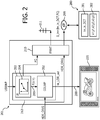
- Fig. 2 shows how our saturation unit can be comprised in a encoder, for yielding HDR video. It gets as input an HDR grading image (HDR_ORIG). Again we elucidate with the example that the grader will make a corresponding LDR image, and use our saturation technology to determine the saturation of that LDR image.
- Color mapper 202 is arranged to apply our saturation mapping as in Fig. 1 , and yield an LDR output image Im_LDR_out, the look of which can be studied on a reference display 220.
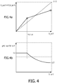
- the grader can specify his desired saturation strategy, e.g. as a multilinear curve specifying the functional mapping between V_in-Y and V_out-Y, as in Fig. 4 , or otherwise.
- the (image or video) encoder 201 comprises a user interface unit 203. It may implement various user interface functionalities, e.g. to determine the luminance reallocation of the various HDR image grey regions into grey regions in the LDR image, e.g. it may allow the user to specify regions of an image to be processed in a different manner from the rest of the image. But one of the comprised units will be a saturation specification unit 204.
- the user may specify his user input USRINP via known grading tool input devices like color grading keyboards, and/or a mouse, etc.
- Color mapper 202 can then apply all specified color transformations, in particular the saturation modification. If the grader is satisfied with the LDR look, the function FC(V-Y) will be the one to use at a receiving side to recreate the appropriate LDR look image out of a received HDR image. Otherwise, the grader may try another F(V-Y) specification.
- the textures are encoded in the original HDR_ORIG, but we could also transmit e.g. the LDR image Im_LDR_out.
- the encoder then needs to collect and format all information by using formatter 210. It will encode the HDR-ORIG image as an MPEG-HEVC image, i.e.
- the metadata FC can e.g. be saved in dedicated SEI images, or similar metadata structures.
- the resulting image signal S_im comprising image data Im_in_DCT and functional color mapping metadata FC for obtaining at least one other look image for a different dynamic range display, may directly be sent over some network, e.g. broadcasted with antenna 211, or may in another embodiment be stored on a memory product 299, say a Bluray disk.
- Fig. 2 also schematically shows the image signal S_im/280 that the Bluray disk contains, which signal is logically composed of at least image data 281, and functional metadata 282.
- the formatter 210 encodes and formats the images and metadata according to an MPEG-family video compression standard, e.g. MPEG-HEVC, with 10bit words for the HDR lumas.
- MPEG-HEVC MPEG-family video compression standard
- FC saturation strategy
- the decoder 301 will get its basic image encoding, and the mapping functions for the chromatic and luminance adaptation via an image input 310, which typically gets combined image data + metadata image signals, and may be connected to various sources such as e.g. a DVB receiver, the internet, a BD reader, etc.
- image input 310 typically gets combined image data + metadata image signals
- sources such as e.g. a DVB receiver, the internet, a BD reader, etc.
- the saturation processing functions in a standalone application such as image processing software, e.g. as a (pre)content generation method
- the image source may be on a computer's hard disk etc.
- the decoder 301 comprises a deformatter 303 for undoing the MPEG decoding, and finally yielding a linear RGB representation of the Im_in_DCT with color components which we assume normalized to 1 for computational simplicity.
- the color mapper 304 will calculate the required LDR image, and it comprises our color saturation processing unit 305 as in Fig. 1 . Indeed, in this example we will do exactly the same function FC as specified in the encoder to do the same downgrading the grader checked on display 220, but there can be other embodiments where one transmits a LDR image, which was created with FC, but needs to be upgraded with an inverse function FC -1 , or only a partial saturation change for a display with peak brightness between the one of the transmitted image, and the reference display corresponding to the image which the applied functions yield when applied to the transmitted image, etc.
- the color mapping may also comprise a gamut mapping to the RGB gamut of the LDR display (for which the LDR image was graded), and the saturation processing will be done in that linear RGB space.
- Receiving side decoding apparatuses comprising our decoder 301 may be manifold, e.g. a settopbox preparing an image for a passive TV, or the color transformation may be done in the TV itself, and the decoding apparatus may generate optimal images for several connected displays of different peak brightness, etc.
- the decoder and encoder may also be in several intermediate apparatuses, e.g. for transforming a first HDR image or video format in a second one, e.g.
- FC is e.g. determined mathematically by analyzing the properties of the images, such as e.g. looking at the histogram or otherwise determining which (how many, how large,...) objects are in the brighter or darker subranges of the total luminance range.
- the specification unit (212) which actually does the generation of the FC function(s) may be different in the two scenarios. In case of user-generated saturation specifications, it will typically include user interface means to specify a functions, e.g.
- the specification unit is of the autoconversion type, there may be one or more image analysis units (not shown), but it may still be advantageous if the encoder shows the (e.g. single, or multiple propositions) automatically generated FC and/or FT, so that he can agree with the artistic quality of those by e.g. clicking an okay button. So the unit arranged to specify a function F(V-Y) encoding gains (g) may either be arranged to do a mathematical specification by itself, or comprise units allowing a human artist to do so. Or, instead of accurately specifying a multisegment saturation strategy, the color grader may just turn one single dial (even directly on a camera to yield appropriate HDR video output), which then mathematically changes the shape of the saturation definition function FC(V-Y).
- Fig. 4 we have given one exemplary simple embodiment, in which the grader needs to change only two parameters.
- Fig. 5 shows the equi-V-Y lines in a yellow-blue slice of the RGB display or codec gamut (shown schematically in a luminance uv-chromaticity representation).
- Fig. 5 shows the disadvantageous asymmetry of the gamut (7% maximum luminance for maximally driven pure blue vs. 93% for yellow), which makes luminance-based saturation difficult, is handled by having the V-Y lines scan through the colors in a different manner.
- Yet another color can be (de)saturated by a different strategy 503, or different amount g2(Y-V). And for the blues we can define yet another saturation amount g3 (504).
- Our described saturation strategy is so interesting, in particular for dynamic range conversion, because, contrary to conventional strategies (applying a constant gain to the difference signals R-Y etc.) which would desaturate the brights like yellows too much, it can desaturate mostly the dark colors like blue, red and magenta, which give the most impact in the brightness-colorfulness optimization.
- the method is easily reversible (if only we design the saturation function to not have too low differential gain), which makes the calculation of FC-1 from FC at the encoder (or even decoder) side simple and robust for those scenarios that would need this.
- the grader can specify a saturation boost scenario in general (note that V-Y also decreases with luminance generally), and a desaturation for the colors that are naturally non-luminous like the blues, and need to be desaturated and boosted. He would specify the former to be e.g. 1.3 up to a chosen control point of Y-V_d1, and then use a linear slope which ends at a desaturation value of e.g. 0.7 for the bright blues (with the high Y-V values). For extreme HDR to LDR conversions we would get much lower end values, e.g. 0.1. Even such a quick specification will give him a good looking LDR image.
- FIG. 4a shows the function V_out-Y vs. V_in-Y of the color transformation, and the lower graph Fig. 4b the corresponding gain.
- the algorithmic components disclosed in this text may (entirely or in part) be realized in practice as hardware (e.g. parts of an application specific IC) or as software running on a special digital signal processor, or a generic processor, etc.
- a memory product should be understood as any physical realization comprising a memory, in particular anything which can be purchased, and non-limitatively covers such embodiments as e.g. an optical disk or other detachable and carryable memory product, or a memory segment on a network-connected server from which the contents of a specific part of the memory can be downloaded, etc.
- the computer program product denotation should be understood to encompass any physical realization of a collection of commands enabling a generic or special purpose processor, after a series of loading steps (which may include intermediate conversion steps, such as translation to an intermediate language, and a final processor language) to enter the commands into the processor, and to execute any of the characteristic functions of an invention.
- the computer program product may be realized as data on a carrier such as e.g. a disk or tape, data present in a memory, data travelling via a network connection -wired or wireless- , or program code on paper.
- characteristic data required for the program may also be embodied as a computer program product.
Landscapes
- Engineering & Computer Science (AREA)
- Multimedia (AREA)
- Signal Processing (AREA)
- Physics & Mathematics (AREA)
- General Physics & Mathematics (AREA)
- Theoretical Computer Science (AREA)
- Image Processing (AREA)
- Processing Of Color Television Signals (AREA)
- Color Image Communication Systems (AREA)
- Compression Or Coding Systems Of Tv Signals (AREA)
- Facsimile Image Signal Circuits (AREA)
Applications Claiming Priority (2)
| Application Number | Priority Date | Filing Date | Title |
|---|---|---|---|
| EP14188425 | 2014-10-10 | ||
| PCT/EP2015/066294 WO2016055178A1 (en) | 2014-10-10 | 2015-07-16 | Saturation processing specification for dynamic range mappings |
Publications (2)
| Publication Number | Publication Date |
|---|---|
| EP3205082A1 EP3205082A1 (en) | 2017-08-16 |
| EP3205082B1 true EP3205082B1 (en) | 2018-04-04 |
Family
ID=51690893
Family Applications (1)
| Application Number | Title | Priority Date | Filing Date |
|---|---|---|---|
| EP15738632.7A Revoked EP3205082B1 (en) | 2014-10-10 | 2015-07-16 | Saturation processing specification for dynamic range mappings |
Country Status (6)
Families Citing this family (25)
| Publication number | Priority date | Publication date | Assignee | Title |
|---|---|---|---|---|
| CN110072091B (zh) * | 2013-10-10 | 2021-12-28 | 杜比实验室特许公司 | 呈现图像数据的方法和多调制投影仪显示器系统 |
| JP2018525905A (ja) * | 2015-07-22 | 2018-09-06 | アリス エンタープライジズ エルエルシーArris Enterprises Llc | 高ダイナミックレンジおよび広色域シーケンスを符号化するシステム |
| KR102711913B1 (ko) * | 2015-08-28 | 2024-09-27 | 앤드류 와이어리스 시스템스 유케이 리미티드 | 높은 동적 범위 및 넓은 컬러 영역 시퀀스들의 코딩에서의 컬러 볼륨 변환들 |
| US10122928B2 (en) * | 2015-09-09 | 2018-11-06 | Red.Com, Llc | Motion video output for multiple displays |
| WO2017127445A1 (en) * | 2016-01-21 | 2017-07-27 | Astral Images Corporation | Processing image content for enabling high dynamic range (hdr) output thereof and computer-readable program product having such hdr content |
| CN108781246B (zh) * | 2016-03-14 | 2021-05-28 | 皇家飞利浦有限公司 | 用于动态范围映射的饱和度处理指定 |
| DE102016003681A1 (de) * | 2016-03-24 | 2017-09-28 | Universität Stuttgart | Datenkompression mittels adaptiven Unterabtastens |
| EP3523976A4 (en) * | 2016-10-05 | 2020-04-29 | Telefonaktiebolaget LM Ericsson (publ) | EFFICIENT IMPLEMENTATION OF LUMINANCE ADJUSTMENT LUT |
| JP6852411B2 (ja) * | 2017-01-19 | 2021-03-31 | ソニー株式会社 | 映像信号処理装置、映像信号処理方法およびプログラム |
| EP3367659A1 (en) * | 2017-02-28 | 2018-08-29 | Thomson Licensing | Hue changing color gamut mapping |
| US10542187B2 (en) * | 2017-03-01 | 2020-01-21 | Canon Kabushiki Kaisha | Image processing apparatus and image processing method |
| EP3566430B1 (en) * | 2017-03-03 | 2022-10-12 | Dolby Laboratories Licensing Corporation | Color saturation adjustment in non-uniform color space |
| US10614326B2 (en) * | 2017-03-06 | 2020-04-07 | Honda Motor Co., Ltd. | System and method for vehicle control based on object and color detection |
| US10380438B2 (en) * | 2017-03-06 | 2019-08-13 | Honda Motor Co., Ltd. | System and method for vehicle control based on red color and green color detection |
| EP3399497A1 (en) | 2017-05-05 | 2018-11-07 | Koninklijke Philips N.V. | Optimizing decoded high dynamic range image saturation |
| US10453375B2 (en) | 2017-06-04 | 2019-10-22 | Apple Inc. | Long-term history of display intensities |
| US10856040B2 (en) * | 2017-10-31 | 2020-12-01 | Avago Technologies International Sales Pte. Limited | Video rendering system |
| EP3493150A1 (en) | 2017-11-30 | 2019-06-05 | InterDigital VC Holdings, Inc. | Tone mapping adaptation for saturation control |
| EP3493542A1 (en) | 2017-11-30 | 2019-06-05 | Thomson Licensing | Saturation control for high-dynamic range reconstruction |
| EP3496028A1 (en) | 2017-12-08 | 2019-06-12 | Koninklijke Philips N.V. | Improved high dynamic range video color remapping |
| CN110691227B (zh) * | 2018-07-05 | 2024-04-09 | 华为技术有限公司 | 一种视频信号处理方法及装置 |
| MX2021001378A (es) * | 2018-09-05 | 2021-04-19 | Koninklijke Philips Nv | Codificacion de video de alto intervalo dinamico (hdr) multi-intervalo. |
| EP3853810B1 (en) * | 2018-09-19 | 2023-10-25 | Dolby Laboratories Licensing Corporation | Automatic display management metadata generation for gaming and/or sdr+ contents |
| CN111754412B (zh) * | 2019-03-29 | 2024-04-19 | Tcl科技集团股份有限公司 | 构建数据对的方法、装置及终端设备 |
| US10735683B1 (en) * | 2019-04-09 | 2020-08-04 | Obsidian Sensors, Inc. | Systems and methods for low-power image digitization |
Citations (3)
| Publication number | Priority date | Publication date | Assignee | Title |
|---|---|---|---|---|
| US20010048476A1 (en) | 1997-05-07 | 2001-12-06 | Hitoshi Nakamura | Picture signal processing apparatus, color video camera and picture signal processing method |
| EP0801509B1 (en) | 1996-04-12 | 2006-07-19 | Sony Corporation | Video camera, video signal processing, video signal compression and video signal conversion |
| WO2014128586A1 (en) | 2013-02-21 | 2014-08-28 | Koninklijke Philips N.V. | Improved hdr image encoding and decoding methods and devices |
Family Cites Families (15)
| Publication number | Priority date | Publication date | Assignee | Title |
|---|---|---|---|---|
| EP0589513B1 (en) | 1992-09-22 | 1998-12-02 | Koninklijke Philips Electronics N.V. | Picture signal processor |
| US5349390A (en) | 1992-09-22 | 1994-09-20 | U.S. Philips Corporation | Picture signal processor for performing both large area and small area contrast reduction, and picture display apparatus incorporating such a picture signal processor |
| BE1007590A3 (nl) * | 1993-10-01 | 1995-08-16 | Philips Electronics Nv | Videosignaalverwerkingsschakeling. |
| JP3134660B2 (ja) | 1994-04-14 | 2001-02-13 | 松下電器産業株式会社 | 色変換方法および色変換装置 |
| JP3509448B2 (ja) | 1996-04-12 | 2004-03-22 | ソニー株式会社 | ビデオカメラ装置、映像信号処理装置、カラー映像信号のレベル圧縮方法および階調変換方法 |
| DE19812526C2 (de) * | 1998-03-21 | 2000-07-20 | Philips Corp Intellectual Pty | Anordnung zur Farbkorrektur von unerlaubten Farben |
| US7743114B1 (en) | 2000-06-30 | 2010-06-22 | Automated Business Companies | Automated data delivery systems |
| WO2002085037A1 (en) | 2001-04-11 | 2002-10-24 | Koninklijke Philips Electronics N.V. | Picture signal contrast control |
| US7057671B2 (en) * | 2002-01-30 | 2006-06-06 | At & T Corp | Image and video processing with chrominance attenuation |
| US8218625B2 (en) * | 2004-04-23 | 2012-07-10 | Dolby Laboratories Licensing Corporation | Encoding, decoding and representing high dynamic range images |
| US7734114B1 (en) * | 2005-12-07 | 2010-06-08 | Marvell International Ltd. | Intelligent saturation of video data |
| PL2543181T3 (pl) | 2010-03-03 | 2016-03-31 | Koninklijke Philips Nv | Urządzenia i sposoby definiowania systemu kolorów |
| ES3030342T3 (en) * | 2011-09-27 | 2025-06-27 | Koninklijke Philips Nv | Apparatus and method for dynamic range transforming of images |
| RU2651225C2 (ru) * | 2012-09-12 | 2018-04-18 | Конинклейке Филипс Н.В. | Выполнение просмотра hdr как процесса, согласованного с владельцем контента |
| RU2642335C2 (ru) * | 2012-10-08 | 2018-01-24 | Конинклейке Филипс Н.В. | Обработка изображений с изменением яркости при цветовых ограничениях |
-
2015
- 2015-07-16 TR TR2018/08347T patent/TR201808347T4/tr unknown
- 2015-07-16 WO PCT/EP2015/066294 patent/WO2016055178A1/en active Application Filing
- 2015-07-16 US US15/515,156 patent/US10313687B2/en active Active
- 2015-07-16 EP EP15738632.7A patent/EP3205082B1/en not_active Revoked
- 2015-07-16 JP JP2017518827A patent/JP6356349B2/ja not_active Expired - Fee Related
- 2015-07-16 CN CN201580067295.7A patent/CN107005716B/zh active Active
Patent Citations (3)
| Publication number | Priority date | Publication date | Assignee | Title |
|---|---|---|---|---|
| EP0801509B1 (en) | 1996-04-12 | 2006-07-19 | Sony Corporation | Video camera, video signal processing, video signal compression and video signal conversion |
| US20010048476A1 (en) | 1997-05-07 | 2001-12-06 | Hitoshi Nakamura | Picture signal processing apparatus, color video camera and picture signal processing method |
| WO2014128586A1 (en) | 2013-02-21 | 2014-08-28 | Koninklijke Philips N.V. | Improved hdr image encoding and decoding methods and devices |
Also Published As
| Publication number | Publication date |
|---|---|
| EP3205082A1 (en) | 2017-08-16 |
| US10313687B2 (en) | 2019-06-04 |
| CN107005716B (zh) | 2020-06-23 |
| CN107005716A (zh) | 2017-08-01 |
| US20170223367A1 (en) | 2017-08-03 |
| TR201808347T4 (tr) | 2018-07-23 |
| JP6356349B2 (ja) | 2018-07-11 |
| WO2016055178A1 (en) | 2016-04-14 |
| JP2017536735A (ja) | 2017-12-07 |
Similar Documents
| Publication | Publication Date | Title |
|---|---|---|
| EP3205082B1 (en) | Saturation processing specification for dynamic range mappings | |
| US10937135B2 (en) | Saturation processing specification for dynamic range mappings | |
| US11521537B2 (en) | Optimized decoded high dynamic range image saturation | |
| JP7203048B2 (ja) | Hdrコード化(復号)のための色域マッピング | |
| RU2642335C2 (ru) | Обработка изображений с изменением яркости при цветовых ограничениях | |
| WO2019170465A1 (en) | Versatile dynamic range conversion processing | |
| EP4111689B1 (en) | Improved hdr color processing for saturated colors | |
| EP4542985A1 (en) | Hdr range adaptation luminance and color processing | |
| EP4607917A1 (en) | Improved encoding and decoding for images | |
| EP4568235A1 (en) | Hdr range adaptation luminance processing on computers | |
| WO2025176560A1 (en) | Encoding and decoding for images |
Legal Events
| Date | Code | Title | Description |
|---|---|---|---|
| STAA | Information on the status of an ep patent application or granted ep patent |
Free format text: STATUS: THE INTERNATIONAL PUBLICATION HAS BEEN MADE |
|
| PUAI | Public reference made under article 153(3) epc to a published international application that has entered the european phase |
Free format text: ORIGINAL CODE: 0009012 |
|
| STAA | Information on the status of an ep patent application or granted ep patent |
Free format text: STATUS: REQUEST FOR EXAMINATION WAS MADE |
|
| 17P | Request for examination filed |
Effective date: 20170511 |
|
| AK | Designated contracting states |
Kind code of ref document: A1 Designated state(s): AL AT BE BG CH CY CZ DE DK EE ES FI FR GB GR HR HU IE IS IT LI LT LU LV MC MK MT NL NO PL PT RO RS SE SI SK SM TR |
|
| AX | Request for extension of the european patent |
Extension state: BA ME |
|
| GRAP | Despatch of communication of intention to grant a patent |
Free format text: ORIGINAL CODE: EPIDOSNIGR1 |
|
| STAA | Information on the status of an ep patent application or granted ep patent |
Free format text: STATUS: GRANT OF PATENT IS INTENDED |
|
| INTG | Intention to grant announced |
Effective date: 20171113 |
|
| DAV | Request for validation of the european patent (deleted) | ||
| DAX | Request for extension of the european patent (deleted) | ||
| GRAS | Grant fee paid |
Free format text: ORIGINAL CODE: EPIDOSNIGR3 |
|
| GRAA | (expected) grant |
Free format text: ORIGINAL CODE: 0009210 |
|
| STAA | Information on the status of an ep patent application or granted ep patent |
Free format text: STATUS: THE PATENT HAS BEEN GRANTED |
|
| AK | Designated contracting states |
Kind code of ref document: B1 Designated state(s): AL AT BE BG CH CY CZ DE DK EE ES FI FR GB GR HR HU IE IS IT LI LT LU LV MC MK MT NL NO PL PT RO RS SE SI SK SM TR |
|
| REG | Reference to a national code |
Ref country code: GB Ref legal event code: FG4D |
|
| REG | Reference to a national code |
Ref country code: CH Ref legal event code: EP |
|
| REG | Reference to a national code |
Ref country code: AT Ref legal event code: REF Ref document number: 986796 Country of ref document: AT Kind code of ref document: T Effective date: 20180415 |
|
| REG | Reference to a national code |
Ref country code: IE Ref legal event code: FG4D |
|
| REG | Reference to a national code |
Ref country code: DE Ref legal event code: R096 Ref document number: 602015009642 Country of ref document: DE |
|
| REG | Reference to a national code |
Ref country code: FR Ref legal event code: PLFP Year of fee payment: 4 |
|
| REG | Reference to a national code |
Ref country code: NL Ref legal event code: MP Effective date: 20180404 |
|
| REG | Reference to a national code |
Ref country code: LT Ref legal event code: MG4D |
|
| PG25 | Lapsed in a contracting state [announced via postgrant information from national office to epo] |
Ref country code: NL Free format text: LAPSE BECAUSE OF FAILURE TO SUBMIT A TRANSLATION OF THE DESCRIPTION OR TO PAY THE FEE WITHIN THE PRESCRIBED TIME-LIMIT Effective date: 20180404 |
|
| PG25 | Lapsed in a contracting state [announced via postgrant information from national office to epo] |
Ref country code: SE Free format text: LAPSE BECAUSE OF FAILURE TO SUBMIT A TRANSLATION OF THE DESCRIPTION OR TO PAY THE FEE WITHIN THE PRESCRIBED TIME-LIMIT Effective date: 20180404 Ref country code: PL Free format text: LAPSE BECAUSE OF FAILURE TO SUBMIT A TRANSLATION OF THE DESCRIPTION OR TO PAY THE FEE WITHIN THE PRESCRIBED TIME-LIMIT Effective date: 20180404 Ref country code: ES Free format text: LAPSE BECAUSE OF FAILURE TO SUBMIT A TRANSLATION OF THE DESCRIPTION OR TO PAY THE FEE WITHIN THE PRESCRIBED TIME-LIMIT Effective date: 20180404 Ref country code: LT Free format text: LAPSE BECAUSE OF FAILURE TO SUBMIT A TRANSLATION OF THE DESCRIPTION OR TO PAY THE FEE WITHIN THE PRESCRIBED TIME-LIMIT Effective date: 20180404 Ref country code: BG Free format text: LAPSE BECAUSE OF FAILURE TO SUBMIT A TRANSLATION OF THE DESCRIPTION OR TO PAY THE FEE WITHIN THE PRESCRIBED TIME-LIMIT Effective date: 20180704 Ref country code: NO Free format text: LAPSE BECAUSE OF FAILURE TO SUBMIT A TRANSLATION OF THE DESCRIPTION OR TO PAY THE FEE WITHIN THE PRESCRIBED TIME-LIMIT Effective date: 20180704 Ref country code: AL Free format text: LAPSE BECAUSE OF FAILURE TO SUBMIT A TRANSLATION OF THE DESCRIPTION OR TO PAY THE FEE WITHIN THE PRESCRIBED TIME-LIMIT Effective date: 20180404 Ref country code: FI Free format text: LAPSE BECAUSE OF FAILURE TO SUBMIT A TRANSLATION OF THE DESCRIPTION OR TO PAY THE FEE WITHIN THE PRESCRIBED TIME-LIMIT Effective date: 20180404 |
|
| PG25 | Lapsed in a contracting state [announced via postgrant information from national office to epo] |
Ref country code: GR Free format text: LAPSE BECAUSE OF FAILURE TO SUBMIT A TRANSLATION OF THE DESCRIPTION OR TO PAY THE FEE WITHIN THE PRESCRIBED TIME-LIMIT Effective date: 20180705 Ref country code: RS Free format text: LAPSE BECAUSE OF FAILURE TO SUBMIT A TRANSLATION OF THE DESCRIPTION OR TO PAY THE FEE WITHIN THE PRESCRIBED TIME-LIMIT Effective date: 20180404 Ref country code: LV Free format text: LAPSE BECAUSE OF FAILURE TO SUBMIT A TRANSLATION OF THE DESCRIPTION OR TO PAY THE FEE WITHIN THE PRESCRIBED TIME-LIMIT Effective date: 20180404 Ref country code: HR Free format text: LAPSE BECAUSE OF FAILURE TO SUBMIT A TRANSLATION OF THE DESCRIPTION OR TO PAY THE FEE WITHIN THE PRESCRIBED TIME-LIMIT Effective date: 20180404 |
|
| REG | Reference to a national code |
Ref country code: AT Ref legal event code: MK05 Ref document number: 986796 Country of ref document: AT Kind code of ref document: T Effective date: 20180404 |
|
| PG25 | Lapsed in a contracting state [announced via postgrant information from national office to epo] |
Ref country code: PT Free format text: LAPSE BECAUSE OF FAILURE TO SUBMIT A TRANSLATION OF THE DESCRIPTION OR TO PAY THE FEE WITHIN THE PRESCRIBED TIME-LIMIT Effective date: 20180806 |
|
| REG | Reference to a national code |
Ref country code: DE Ref legal event code: R026 Ref document number: 602015009642 Country of ref document: DE |
|
| PLBI | Opposition filed |
Free format text: ORIGINAL CODE: 0009260 |
|
| PLAX | Notice of opposition and request to file observation + time limit sent |
Free format text: ORIGINAL CODE: EPIDOSNOBS2 |
|
| PG25 | Lapsed in a contracting state [announced via postgrant information from national office to epo] |
Ref country code: SK Free format text: LAPSE BECAUSE OF FAILURE TO SUBMIT A TRANSLATION OF THE DESCRIPTION OR TO PAY THE FEE WITHIN THE PRESCRIBED TIME-LIMIT Effective date: 20180404 Ref country code: EE Free format text: LAPSE BECAUSE OF FAILURE TO SUBMIT A TRANSLATION OF THE DESCRIPTION OR TO PAY THE FEE WITHIN THE PRESCRIBED TIME-LIMIT Effective date: 20180404 Ref country code: DK Free format text: LAPSE BECAUSE OF FAILURE TO SUBMIT A TRANSLATION OF THE DESCRIPTION OR TO PAY THE FEE WITHIN THE PRESCRIBED TIME-LIMIT Effective date: 20180404 Ref country code: RO Free format text: LAPSE BECAUSE OF FAILURE TO SUBMIT A TRANSLATION OF THE DESCRIPTION OR TO PAY THE FEE WITHIN THE PRESCRIBED TIME-LIMIT Effective date: 20180404 Ref country code: AT Free format text: LAPSE BECAUSE OF FAILURE TO SUBMIT A TRANSLATION OF THE DESCRIPTION OR TO PAY THE FEE WITHIN THE PRESCRIBED TIME-LIMIT Effective date: 20180404 Ref country code: CZ Free format text: LAPSE BECAUSE OF FAILURE TO SUBMIT A TRANSLATION OF THE DESCRIPTION OR TO PAY THE FEE WITHIN THE PRESCRIBED TIME-LIMIT Effective date: 20180404 |
|
| 26 | Opposition filed |
Opponent name: MOLNIA, DAVID Effective date: 20190104 |
|
| PG25 | Lapsed in a contracting state [announced via postgrant information from national office to epo] |
Ref country code: SM Free format text: LAPSE BECAUSE OF FAILURE TO SUBMIT A TRANSLATION OF THE DESCRIPTION OR TO PAY THE FEE WITHIN THE PRESCRIBED TIME-LIMIT Effective date: 20180404 Ref country code: IT Free format text: LAPSE BECAUSE OF FAILURE TO SUBMIT A TRANSLATION OF THE DESCRIPTION OR TO PAY THE FEE WITHIN THE PRESCRIBED TIME-LIMIT Effective date: 20180404 |
|
| REG | Reference to a national code |
Ref country code: CH Ref legal event code: PL |
|
| PG25 | Lapsed in a contracting state [announced via postgrant information from national office to epo] |
Ref country code: MC Free format text: LAPSE BECAUSE OF FAILURE TO SUBMIT A TRANSLATION OF THE DESCRIPTION OR TO PAY THE FEE WITHIN THE PRESCRIBED TIME-LIMIT Effective date: 20180404 Ref country code: LU Free format text: LAPSE BECAUSE OF NON-PAYMENT OF DUE FEES Effective date: 20180716 |
|
| PLBB | Reply of patent proprietor to notice(s) of opposition received |
Free format text: ORIGINAL CODE: EPIDOSNOBS3 |
|
| REG | Reference to a national code |
Ref country code: BE Ref legal event code: MM Effective date: 20180731 |
|
| REG | Reference to a national code |
Ref country code: IE Ref legal event code: MM4A |
|
| PG25 | Lapsed in a contracting state [announced via postgrant information from national office to epo] |
Ref country code: IE Free format text: LAPSE BECAUSE OF NON-PAYMENT OF DUE FEES Effective date: 20180716 Ref country code: LI Free format text: LAPSE BECAUSE OF NON-PAYMENT OF DUE FEES Effective date: 20180731 Ref country code: CH Free format text: LAPSE BECAUSE OF NON-PAYMENT OF DUE FEES Effective date: 20180731 |
|
| PG25 | Lapsed in a contracting state [announced via postgrant information from national office to epo] |
Ref country code: BE Free format text: LAPSE BECAUSE OF NON-PAYMENT OF DUE FEES Effective date: 20180731 |
|
| PGFP | Annual fee paid to national office [announced via postgrant information from national office to epo] |
Ref country code: TR Payment date: 20190704 Year of fee payment: 5 Ref country code: FR Payment date: 20190726 Year of fee payment: 5 |
|
| PGFP | Annual fee paid to national office [announced via postgrant information from national office to epo] |
Ref country code: GB Payment date: 20190729 Year of fee payment: 5 |
|
| PG25 | Lapsed in a contracting state [announced via postgrant information from national office to epo] |
Ref country code: MT Free format text: LAPSE BECAUSE OF NON-PAYMENT OF DUE FEES Effective date: 20180716 |
|
| PGFP | Annual fee paid to national office [announced via postgrant information from national office to epo] |
Ref country code: DE Payment date: 20190930 Year of fee payment: 5 |
|
| RDAF | Communication despatched that patent is revoked |
Free format text: ORIGINAL CODE: EPIDOSNREV1 |
|
| REG | Reference to a national code |
Ref country code: DE Ref legal event code: R064 Ref document number: 602015009642 Country of ref document: DE Ref country code: DE Ref legal event code: R103 Ref document number: 602015009642 Country of ref document: DE |
|
| RAP2 | Party data changed (patent owner data changed or rights of a patent transferred) |
Owner name: KONINKLIJKE PHILIPS N.V. |
|
| PG25 | Lapsed in a contracting state [announced via postgrant information from national office to epo] |
Ref country code: MK Free format text: LAPSE BECAUSE OF NON-PAYMENT OF DUE FEES Effective date: 20180404 Ref country code: CY Free format text: LAPSE BECAUSE OF FAILURE TO SUBMIT A TRANSLATION OF THE DESCRIPTION OR TO PAY THE FEE WITHIN THE PRESCRIBED TIME-LIMIT Effective date: 20180404 Ref country code: HU Free format text: LAPSE BECAUSE OF FAILURE TO SUBMIT A TRANSLATION OF THE DESCRIPTION OR TO PAY THE FEE WITHIN THE PRESCRIBED TIME-LIMIT; INVALID AB INITIO Effective date: 20150716 |
|
| RDAG | Patent revoked |
Free format text: ORIGINAL CODE: 0009271 |
|
| STAA | Information on the status of an ep patent application or granted ep patent |
Free format text: STATUS: PATENT REVOKED |
|
| PG25 | Lapsed in a contracting state [announced via postgrant information from national office to epo] |
Ref country code: IS Free format text: LAPSE BECAUSE OF FAILURE TO SUBMIT A TRANSLATION OF THE DESCRIPTION OR TO PAY THE FEE WITHIN THE PRESCRIBED TIME-LIMIT Effective date: 20180804 |
|
| REG | Reference to a national code |
Ref country code: FI Ref legal event code: MGE |
|
| 27W | Patent revoked |
Effective date: 20200308 |
|
| GBPR | Gb: patent revoked under art. 102 of the ep convention designating the uk as contracting state |
Effective date: 20200308 |
|
| PG25 | Lapsed in a contracting state [announced via postgrant information from national office to epo] |
Ref country code: SI Free format text: LAPSE BECAUSE OF NON-PAYMENT OF DUE FEES Effective date: 20180716 |
|
| PLAB | Opposition data, opponent's data or that of the opponent's representative modified |
Free format text: ORIGINAL CODE: 0009299OPPO |
|
| R26 | Opposition filed (corrected) |
Opponent name: MOLNIA, DAVID Effective date: 20190104 |