EP3204986B1 - Vorrichtung zur bereitstellung von drahtloser energieübertragung - Google Patents
Vorrichtung zur bereitstellung von drahtloser energieübertragung Download PDFInfo
- Publication number
- EP3204986B1 EP3204986B1 EP15753835.6A EP15753835A EP3204986B1 EP 3204986 B1 EP3204986 B1 EP 3204986B1 EP 15753835 A EP15753835 A EP 15753835A EP 3204986 B1 EP3204986 B1 EP 3204986B1
- Authority
- EP
- European Patent Office
- Prior art keywords
- antenna
- lens
- energy
- end portion
- primary
- Prior art date
- Legal status (The legal status is an assumption and is not a legal conclusion. Google has not performed a legal analysis and makes no representation as to the accuracy of the status listed.)
- Active
Links
Images

Classifications
-
- H—ELECTRICITY
- H02—GENERATION; CONVERSION OR DISTRIBUTION OF ELECTRIC POWER
- H02J—ELECTRIC POWER NETWORKS; CIRCUIT ARRANGEMENTS OR SYSTEMS FOR SUPPLYING OR DISTRIBUTING ELECTRIC POWER; SYSTEMS FOR STORING ELECTRIC ENERGY
- H02J50/00—Circuit arrangements or systems for wireless supply or distribution of electric power
- H02J50/20—Circuit arrangements or systems for wireless supply or distribution of electric power using microwaves or radio frequency waves
- H02J50/23—Circuit arrangements or systems for wireless supply or distribution of electric power using microwaves or radio frequency waves characterised by the type of transmitting antennas, e.g. directional array antennas or Yagi antennas
-
- H—ELECTRICITY
- H01—ELECTRIC ELEMENTS
- H01Q—ANTENNAS, i.e. RADIO AERIALS
- H01Q11/00—Electrically-long antennas having dimensions more than twice the shortest operating wavelength and consisting of conductive active radiating elements
- H01Q11/02—Non-resonant antennas, e.g. travelling-wave antenna
- H01Q11/08—Helical antennas
-
- H—ELECTRICITY
- H01—ELECTRIC ELEMENTS
- H01Q—ANTENNAS, i.e. RADIO AERIALS
- H01Q15/00—Devices for reflection, refraction, diffraction or polarisation of waves radiated from an antenna, e.g. quasi-optical devices
- H01Q15/02—Refracting or diffracting devices, e.g. lens, prism
-
- H—ELECTRICITY
- H01—ELECTRIC ELEMENTS
- H01Q—ANTENNAS, i.e. RADIO AERIALS
- H01Q19/00—Combinations of primary active antenna elements and units with secondary devices, e.g. with quasi-optical devices, for giving the antenna a desired directional characteristic
- H01Q19/06—Combinations of primary active antenna elements and units with secondary devices, e.g. with quasi-optical devices, for giving the antenna a desired directional characteristic using refracting or diffracting devices, e.g. lens
- H01Q19/062—Combinations of primary active antenna elements and units with secondary devices, e.g. with quasi-optical devices, for giving the antenna a desired directional characteristic using refracting or diffracting devices, e.g. lens for focusing
-
- H—ELECTRICITY
- H01—ELECTRIC ELEMENTS
- H01Q—ANTENNAS, i.e. RADIO AERIALS
- H01Q7/00—Loop antennas with a substantially uniform current distribution around the loop and having a directional radiation pattern in a plane perpendicular to the plane of the loop
-
- H—ELECTRICITY
- H02—GENERATION; CONVERSION OR DISTRIBUTION OF ELECTRIC POWER
- H02J—ELECTRIC POWER NETWORKS; CIRCUIT ARRANGEMENTS OR SYSTEMS FOR SUPPLYING OR DISTRIBUTING ELECTRIC POWER; SYSTEMS FOR STORING ELECTRIC ENERGY
- H02J50/00—Circuit arrangements or systems for wireless supply or distribution of electric power
- H02J50/20—Circuit arrangements or systems for wireless supply or distribution of electric power using microwaves or radio frequency waves
- H02J50/27—Circuit arrangements or systems for wireless supply or distribution of electric power using microwaves or radio frequency waves characterised by the type of receiving antennas, e.g. rectennas
-
- H—ELECTRICITY
- H02—GENERATION; CONVERSION OR DISTRIBUTION OF ELECTRIC POWER
- H02J—ELECTRIC POWER NETWORKS; CIRCUIT ARRANGEMENTS OR SYSTEMS FOR SUPPLYING OR DISTRIBUTING ELECTRIC POWER; SYSTEMS FOR STORING ELECTRIC ENERGY
- H02J50/00—Circuit arrangements or systems for wireless supply or distribution of electric power
- H02J50/70—Circuit arrangements or systems for wireless supply or distribution of electric power involving the reduction of electric, magnetic or electromagnetic leakage fields
-
- H—ELECTRICITY
- H01—ELECTRIC ELEMENTS
- H01Q—ANTENNAS, i.e. RADIO AERIALS
- H01Q17/00—Devices for absorbing waves radiated from an antenna; Combinations of such devices with active antenna elements or systems
Definitions
- the present disclosure relates to wireless energy transmission and other applications.
- Battery powered wireless sensors are required to be in close proximity to the mains (wall, generator, inverter, etc.) powered base station as communication range is limited for battery powered devices.
- Mains powered base stations restricts the location of the sensor to be in close proximity to the mains power. Mains power may be installed nearly anywhere, however, installing mains power conduit, junction boxes, outlets, etc. can be expensive and further, placing a sensor and a mains powered base station in the most preferable location may create unwanted exposure of wires and junction boxes which can distract from the aesthetics of a space.
- Mains powered base stations may have battery backup, but battery size limits the available power and duration over which the base stations may continue to operate before all battery energy is expended.
- WO2012/148450 discloses a system for providing wireless power transfer, comprising a primary antenna and a secondary antenna, each antenna having a lens surrounding the respective antenna, wherein the primary and secondary antennas are separated a distance apart to wirelessly transfer power from the primary antenna to the secondary antenna.
- a device for providing wireless power transfer including the technical features as set out in claim 1.
- FIG. 1 a partial view of an exemplary embodiment of a system of wireless power transfer in accordance with the disclosure is shown in Fig. 1 and is designated generally by reference character 100.
- FIGs. 2-7 Other embodiments of the system and device for wireless power transfer in accordance with the disclosure, or aspects thereof, are provided in Figs. 2-7 , as will be described.
- Fig. 1 is a block diagram of a wireless energy transfer system 100 according to the present disclosure.
- the wireless energy transfer system 100 allows energy for use in providing power and/or data communications to be transferred wirelessly from a source (e.g., a mains power source) to a load (e.g., an electrical device) based on the concept of nonradiative near fields of resonators (referred to as nonradiative resonant coupling).
- a source e.g., a mains power source
- a load e.g., an electrical device
- the wireless energy transfer system 100 is implemented using primarily near-field energy.
- the system 100 includes an RF signal generator 102 operatively coupled to an optional power amplifier 104.
- the RF signal generator is the source of energy and can be a mains powered energy source or the like.
- the RF signal generator 102 generates an RF energy signal 106, which is (optionally) amplified by a power amplifier 104 to produce an amplified RF energy signal 110.
- RF Signal generator 102 may generate a full wave rectified signal, sinusoid or combination of full wave rectified and sinusoids. Further, the signal from the RF signal generator 102 may or may not be modulated for carrying data.
- the system further includes an electromagnetic transmitter device 112 for wireless transferring of the RF energy signal.
- An electromagnetic receiver device 114 is separated a distance apart from the transmitter device 112 and acts to receive the RF energy signal.
- Each of the transmitting device and receiving device 112 and 124 may be operatively connected to optional transceivers 112a and 114a for allowing the transfer of data.
- Each of the transmitting device and the receiving device 112 and 114 includes a low frequency near-field RF lens (described in greater detail below with respect to Fig. 2 ) to transmit and receive the near-field RF signal.
- the lens of the receiver device converts the near-field RF energy to either a direct or alternating electrical current which is then directed into the load 116 or more specifically an electrical device, such as a sensor.
- the system of Figure 1 could also be used to wirelessly communicate data between primary and secondary devices. The data may be used for communication, radar or other purposes.
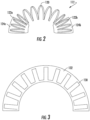
- Fig. 2 is a top view of an exemplary transmitter and receiver device as used in system 100.
- the devices include an antenna 120 which may be a loop-type with many turns for creating high electromagnetic field versus current characteristics.
- Antenna 120 is configured in a partial toroidal helix shape to be substantially non-resonant such that far-field signals, i.e., radiated field signals, are minimized and near-field signals are maximized.
- the antenna 120 has a first and second lens 124a, 124b.
- Each of the first and second lenses 124a, 124b are positioned at first and second end portions 122a, 122b, respectively, of the antenna with no other lenses or antennas therebetween. More specifically, the lenses 124a, 124b surround the first and second end portions 122a, 122b of antenna 120.
- the lenses 124a, 124b are comprised of an array of resonators. The lenses 124a, 124b force electromagnetic energy towards the opposing antenna by reducing or preventing self-cancellation of the near-field, as shown in Fig. 7 .
- the lenses 124a, 124b reduce the amount of electromagnetic energy from the antenna 120 from closing/self-cancelling immediately at the two mouths of the antenna 120.
- the lenses 124a, 124b positioned at the end portions 122a, 122b of the antenna 120 have a tighter tolerance than a lens distributed over the entirety of the antenna 120.
- a substantial portion of the antenna 120 is not controlled by either lens 124a, 124b. Therefore, the electromagnetic fields in the uncontrolled region are directed towards one mouth of the antenna 120 on the inside of the antenna 120 and the other mouth of antenna 120 on the outside of antenna 120.
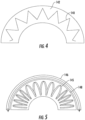
- Figs. 3-4 and 7 illustrate top views of other examples being not part of the invention of antennas 130, 140, 149 for use as transmitter and receiver devices 112, 114 in system 100.
- Antenna 130 is configured as a meander line antenna
- antenna 140 is configured as a meander line antenna with triangular peaks
- antenna 149 is a linear antenna.
- meander line antenna 130, meander line antenna with triangular peaks 140, and linear antenna 149 include lenses 132, 142, 150 respectively, which cover the entirety of the antennas 130, 140, 149.
- the meander line antenna 130, the triangle antenna 140, and the linear antenna 149 allow for directing energy on the back/far side of the lens/antenna towards another lens/antenna.
- the uniform geometry of the meander line antenna 130, the triangle antenna 140, and the linear antenna 149 simplify the lens design.
- the uniform geometry results in simplified spacing between the lens elements and minimizes impediments to view of an opposing antenna which allows for less current/field cancellation, resulting in a design which has higher efficiency, is easier to design, lower cost, and easier to manufacture.
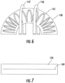
- a longer lens element for example, a light pipe, which transports the energy to a point where the energy has an unobstructed view of the opposing antenna.
- Figs. 5 and 6 illustrate yet another examples being not part of the invention of an antenna 145 in a partial toroidal helix shape that may be used with transmitter and receiver devices 112, 114.
- antenna 145 is surrounded in its entirety by lens 148.
- Light pipe 146 is positioned on a back side of antenna 145. The energy from the back side of the antenna 145 is directed through the light pipes 146, 148, respectively, towards an opposing antenna.
- Fig. 5 illustrate yet another examples being not part of the invention of an antenna 145 in a partial toroidal helix shape that may be used with transmitter and receiver devices 112, 114.
- antenna 145 is surrounded in its entirety by lens 148.
- Light pipe 146 is positioned on a back side of antenna 145. The energy from the back side of the antenna 145 is directed through the light pipes 146,
- a plurality of light pipes 146 and 147 are positioned arching over the back side of the antenna 145.
- the light pipes 146 and 147 create a shorter and efficient path for the transfer of energy.
- the energy may be transported to a convenient position by adding layers to the lens which gradually move the energy away from and to the side or top of the lens.
- Light pipes 146, 147 direct electromagnetic energy from the back side of the antenna and lens which has an obstructed view (from an electromagnetic perspective) of the target antenna and lens.
- the light pipes are low-loss and low-cancellation subwavelength sized resonators used to direct electromagnetic energy similar to the lens material.
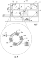
- Fig. 8 is an example of a wireless system 150 using the transmitter and receiver devices 112, 114 of Fig. 2, 3 , 4, 5 , 6 and/or 7 and system of Fig. 1 . It will be understood by those skilled in the art that this a security system as shown and described below is one example for the use of the devices, however, any system having electric or electronic devices requiring wireless energy power transfer is contemplated without departing from the scope of the invention. Shown in Fig. 8 is a multi-level structure having several doors, windows and a kitchen. The security system includes a plurality of sensors. Sensors can be of types commercially available and known in the art.
- sensors S1, S2, S3, S4 can be positioned at each window and door and used by the security system to notify occupants if a window or door is left open.
- Sensors S5, S6, S7 can be smoke/fire alarms positioned in the kitchen and bedrooms.
- Each of the sensors S1, S2, S3, S4, S5, S6 and S7 may be wirelessly powered or battery powered electronic devices.
- Mains power sources P1, P2, P3, P4 are locating throughout the home.
- a respective transmitter device 112 is operatively connected to each wall power source P1, P2, P3, P4 and a respective receiver device 114 is operatively connected to each sensor S1, S2, S3, S4, S5, S6 and S7.
- the respective transmitter device 112 can be separated a distance apart from the respective receiver device so as not to interfere with the design and aesthetics of the space.
- a transmitter device may transfer energy to more than one receiver device and therefore more than one sensor.
- wall power source P1 is transmitting energy to sensors S1 and S7 and power source P4 provides backup power to the entire system from a source of a bank of car batteries in the basement.
- Fig. 9 shows a detailed view of the transmitter device 112 connected to mains power source P3 and receiver device 114 connected to sensor/load S4. In operation, as shown schematically in Fig. 1 , the transmitter device 112 receives the amplified RF energy signal from the wall power source P3 and the amplifier 104.
- the transmitter device 112 causes RF energy to be wirelessly transmitted between the transmitter device 112 and the receiver device 114.
- First and second lenses 124a, 124b of the transmitter device 112 are directed towards the first and second lenses 126a, 126b of the receiver device 114 to direct the transfer of energy.
- the first and second lenses 126a, 126b of the receiver device 114 convert the electromagnetic fields to an electrical signal, which is received by the sensor S4. In this manner near-field energy is wirelessly transferred to provide power to an electrical or electronic device. Power may be transmitted continuously or in a periodic manner. Low frequency electromagnetic energy penetrates most materials well except metal.
- the system can even be used to provide power through a metal barrier/wall, but the efficiency will be reduced as the metal wall will absorb, reflect and defocus the fields as they pass through the metal, particularly good conductors of magnetic fields such as iron.
- the efficiency will be reduced as the metal wall will absorb, reflect and defocus the fields as they pass through the metal, particularly good conductors of magnetic fields such as iron.
- a wireless power transmitter on the other side of the metal barrier or mains power needs to be provided.
- the lenses may be used to relay data wirelessly between sensors, base stations and/or act as a redundant communication backup for the base station.
- the very high directivity of the lenses, non-radiative nature of the lenses (e.g. far-field cancelling), low path loss in most instances and very high bit energy of emissions make communication interference quite robust and reduces susceptibility to interference.
- the lenses may be used as part of a Multiple-Input-Multiple-Output (MIMO) or tomography radar used to detect and track objects and people in the area under protection of the security system.
- MIMO Multiple-Input-Multiple-Output
- Such a radar would characterize the surroundings by the power emissions and/or communication emissions and/or by passively sensing the electromagnetic emissions not under the control of the security or wireless power system.
- this disclosure relates to wireless energy transfer using electromagnetic resonators.
- electromagnetic resonator type
- wireless energy transfer systems described herein are more general and may be implemented using a wide variety of resonators and resonant objects.
Landscapes
- Engineering & Computer Science (AREA)
- Computer Networks & Wireless Communication (AREA)
- Power Engineering (AREA)
- Physics & Mathematics (AREA)
- Electromagnetism (AREA)
- Aerials With Secondary Devices (AREA)
- Near-Field Transmission Systems (AREA)
Claims (3)
- Vorrichtung zum Bereitstellen von drahtloser Energieübertragung, Folgendes umfassend:eine Primärantenne (112), die eine erste Linse (124a), die einen ersten Endabschnitt (112a) davon umgibt, und eine zweite Linse (124b) aufweist, die einen zweiten Endabschnitt (122b) davon umgibt, wobei die erste Linse (124a) und die zweite Linse (124b) nicht miteinander in Kontakt sind und keine anderen Linsen oder Antennen zwischen der ersten Linse (124a) und der zweiten Linse (124b) vorhanden sind; undeine Sekundärantenne (114), die eine erste Linse (126a), die einen ersten Endabschnitt der Sekundärantenne umgibt, und eine zweite Linse (126b) aufweist, die einen zweiten Endabschnitt der Sekundärantenne umgibt, wobei die Primärantenne (112) eine elektromagnetische Übertragungsspule ist und die Sekundärantenne (114) ein elektromagnetischer Empfänger ist; undeine Netzstromquelle (P3), die betriebsmäßig verbunden ist, um die Primärantenne (112) zu versorgen, wobei die Primär- und die Sekundärantenne (112, 114) in einem Abstand voneinander getrennt sind, um drahtlos Strom von der Primärantenne auf die Sekundärantenne zu übertragen;wobei die Primärantenne (112) und die erste und zweite Linse der Primärantenne (124a, 124b) elektromagnetische Energie in Richtung der Sekundärantenne (114) und der ersten und zweiten Linse der Sekundärantenne (126a, 126b) in einer Weise zwingen, die eine Feldselbstauslöschung verhindert.
- Vorrichtung nach Anspruch 1, wobei der erste Endabschnitt (122a) und der zweite Endabschnitt (122b) der Primärantenne (112) auf den ersten Endabschnitt und den zweiten Endabschnitt der Sekundärantenne (114) gerichtet sind.
- Vorrichtung nach Anspruch 1 oder 2, wobei die erste und zweite Linse (124a, 124b; 126a, 126b) jeder der Primär- und Sekundärantenne (112, 114) eine Anordnung von Resonatoren umfassen.
Priority Applications (1)
| Application Number | Priority Date | Filing Date | Title |
|---|---|---|---|
| EP24165666.9A EP4366086A3 (de) | 2014-10-09 | 2015-08-12 | Vorrichtung zur bereitstellung von drahtloser energieübertragung |
Applications Claiming Priority (2)
| Application Number | Priority Date | Filing Date | Title |
|---|---|---|---|
| US201462061905P | 2014-10-09 | 2014-10-09 | |
| PCT/US2015/044822 WO2016057115A1 (en) | 2014-10-09 | 2015-08-12 | Device for providing wireless energy transfer |
Related Child Applications (1)
| Application Number | Title | Priority Date | Filing Date |
|---|---|---|---|
| EP24165666.9A Division EP4366086A3 (de) | 2014-10-09 | 2015-08-12 | Vorrichtung zur bereitstellung von drahtloser energieübertragung |
Publications (2)
| Publication Number | Publication Date |
|---|---|
| EP3204986A1 EP3204986A1 (de) | 2017-08-16 |
| EP3204986B1 true EP3204986B1 (de) | 2024-04-17 |
Family
ID=53938428
Family Applications (2)
| Application Number | Title | Priority Date | Filing Date |
|---|---|---|---|
| EP15753835.6A Active EP3204986B1 (de) | 2014-10-09 | 2015-08-12 | Vorrichtung zur bereitstellung von drahtloser energieübertragung |
| EP24165666.9A Pending EP4366086A3 (de) | 2014-10-09 | 2015-08-12 | Vorrichtung zur bereitstellung von drahtloser energieübertragung |
Family Applications After (1)
| Application Number | Title | Priority Date | Filing Date |
|---|---|---|---|
| EP24165666.9A Pending EP4366086A3 (de) | 2014-10-09 | 2015-08-12 | Vorrichtung zur bereitstellung von drahtloser energieübertragung |
Country Status (3)
| Country | Link |
|---|---|
| US (2) | US11411439B2 (de) |
| EP (2) | EP3204986B1 (de) |
| WO (1) | WO2016057115A1 (de) |
Families Citing this family (3)
| Publication number | Priority date | Publication date | Assignee | Title |
|---|---|---|---|---|
| US11916398B2 (en) * | 2021-12-29 | 2024-02-27 | Energous Corporation | Small form-factor devices with integrated and modular harvesting receivers, and shelving-mounted wireless-power transmitters for use therewith |
| US12142939B2 (en) | 2022-05-13 | 2024-11-12 | Energous Corporation | Integrated wireless-power-transmission platform designed to operate in multiple bands, and multi-band antennas for use therewith |
| US20250208442A1 (en) * | 2023-12-20 | 2025-06-26 | Meta Platforms Technologies, Llc | Apparatus, system, and method for wirelessly powering electrical components on optical elements of eyewear frames |
Family Cites Families (12)
| Publication number | Priority date | Publication date | Assignee | Title |
|---|---|---|---|---|
| US6275143B1 (en) | 1997-05-09 | 2001-08-14 | Anatoli Stobbe | Security device having wireless energy transmission |
| WO2001037374A1 (en) | 1999-11-18 | 2001-05-25 | Automotive Systems Laboratory, Inc. | Multi-beam antenna |
| US7443057B2 (en) | 2004-11-29 | 2008-10-28 | Patrick Nunally | Remote power charging of electronic devices |
| JP2010503368A (ja) | 2006-09-01 | 2010-01-28 | パワーキャスト コーポレイション | ハイブリッドパワー取り出しおよび方法 |
| US7928900B2 (en) * | 2006-12-15 | 2011-04-19 | Alliant Techsystems Inc. | Resolution antenna array using metamaterials |
| EP2120705A1 (de) | 2006-12-21 | 2009-11-25 | Koninklijke Philips Electronics N.V. | Drahtlose interventionelle vorrichtung und system für drahtlose energieübertragung |
| US8723722B2 (en) | 2008-08-28 | 2014-05-13 | Alliant Techsystems Inc. | Composites for antennas and other applications |
| US8890366B2 (en) | 2010-09-30 | 2014-11-18 | Mitsubishi Electric Research Laboratories, Inc. | Wireless energy transfer using array of resonant objects |
| US20120274147A1 (en) | 2011-04-28 | 2012-11-01 | Alliant Techsystems Inc. | Wireless energy transmission using near-field energy |
| US8594572B1 (en) | 2011-06-16 | 2013-11-26 | The United States Of America As Represented By The Secretary Of The Navy | Wireless electric power transmission through wall |
| US9118354B2 (en) * | 2011-08-30 | 2015-08-25 | Apple Inc. | Electronic device with shared near field communications element |
| JP5890191B2 (ja) * | 2012-02-06 | 2016-03-22 | トヨタ自動車株式会社 | 送電装置、受電装置、および電力伝送システム |
-
2015
- 2015-08-12 US US15/517,748 patent/US11411439B2/en active Active
- 2015-08-12 WO PCT/US2015/044822 patent/WO2016057115A1/en not_active Ceased
- 2015-08-12 EP EP15753835.6A patent/EP3204986B1/de active Active
- 2015-08-12 EP EP24165666.9A patent/EP4366086A3/de active Pending
-
2022
- 2022-08-08 US US17/882,791 patent/US12113369B2/en active Active
Also Published As
| Publication number | Publication date |
|---|---|
| EP3204986A1 (de) | 2017-08-16 |
| EP4366086A2 (de) | 2024-05-08 |
| US12113369B2 (en) | 2024-10-08 |
| WO2016057115A1 (en) | 2016-04-14 |
| US20170310165A1 (en) | 2017-10-26 |
| EP4366086A3 (de) | 2024-07-17 |
| US11411439B2 (en) | 2022-08-09 |
| US20230187974A1 (en) | 2023-06-15 |
Similar Documents
| Publication | Publication Date | Title |
|---|---|---|
| US12113369B2 (en) | Device for providing wireless energy transfer | |
| US8378524B2 (en) | Non-contact power transmission device | |
| KR101755724B1 (ko) | 전자 디바이스를 위한 무선 전력공급 및 무선 통신 | |
| EP3234639B1 (de) | Radarsystem mit mehreren sende-empfängern zur überwachung und erkennung von zielen innerhalb eines überwachungsbereichs | |
| EP2761723B1 (de) | Drahtloser stromsender, drahtloser stromempfänger und drahtloses stromübertragungsverfahren | |
| KR101704834B1 (ko) | 무선 전력 송신에서의 임피던스 변화 검출 | |
| JP4772744B2 (ja) | 非接触給電装置用の信号伝送コイル通信装置 | |
| EP2545628B1 (de) | Erkennung und schutz von vorrichtungen in einem drahtlosenergiesystem | |
| CN108122668B (zh) | 感应共振整合型无线充电发射器的线圈结构及控制方法 | |
| US20120153894A1 (en) | Wireless energy transfer and continuous radio station signal coexistence | |
| US20140266034A1 (en) | Short Distance Wireless Device Charging System having a Shared Antenna | |
| KR20110115598A (ko) | 재생가능한 에너지로부터의 무선 전력 | |
| KR101350309B1 (ko) | 특정 무선 충전기기로 송신전력을 집중할 수 있는 무선 전력전송 장치 및 방법 | |
| JP6471382B2 (ja) | 磁力波アンテナおよびそれを用いる磁力波通信装置 | |
| JP2010503368A (ja) | ハイブリッドパワー取り出しおよび方法 | |
| TW201004089A (en) | Wireless power transfer for appliances and equipments | |
| EP3298429B1 (de) | Verfahren und vorrichtung mit td-zugriff mehrerer radarmodule bei der detektion lebender objekte für drahtlosleistungsübertragungsanwendungen | |
| EP3567673A1 (de) | Kombinationsantenne | |
| KR102637679B1 (ko) | 무선 전력 송수신 장치 | |
| US8823219B2 (en) | Headset for receiving wireless power | |
| US10224762B2 (en) | Living-object protection system antenna structure | |
| JP6275470B2 (ja) | ワイヤレス給電システム | |
| KR20180131998A (ko) | 무선 전력 전송 장치 | |
| JP5541461B2 (ja) | 通信装置 | |
| JP6760326B2 (ja) | 通信補助ユニット |
Legal Events
| Date | Code | Title | Description |
|---|---|---|---|
| STAA | Information on the status of an ep patent application or granted ep patent |
Free format text: STATUS: THE INTERNATIONAL PUBLICATION HAS BEEN MADE |
|
| PUAI | Public reference made under article 153(3) epc to a published international application that has entered the european phase |
Free format text: ORIGINAL CODE: 0009012 |
|
| STAA | Information on the status of an ep patent application or granted ep patent |
Free format text: STATUS: REQUEST FOR EXAMINATION WAS MADE |
|
| 17P | Request for examination filed |
Effective date: 20170504 |
|
| AK | Designated contracting states |
Kind code of ref document: A1 Designated state(s): AL AT BE BG CH CY CZ DE DK EE ES FI FR GB GR HR HU IE IS IT LI LT LU LV MC MK MT NL NO PL PT RO RS SE SI SK SM TR |
|
| AX | Request for extension of the european patent |
Extension state: BA ME |
|
| DAV | Request for validation of the european patent (deleted) | ||
| DAX | Request for extension of the european patent (deleted) | ||
| STAA | Information on the status of an ep patent application or granted ep patent |
Free format text: STATUS: EXAMINATION IS IN PROGRESS |
|
| 17Q | First examination report despatched |
Effective date: 20200401 |
|
| GRAP | Despatch of communication of intention to grant a patent |
Free format text: ORIGINAL CODE: EPIDOSNIGR1 |
|
| STAA | Information on the status of an ep patent application or granted ep patent |
Free format text: STATUS: GRANT OF PATENT IS INTENDED |
|
| INTG | Intention to grant announced |
Effective date: 20231108 |
|
| GRAS | Grant fee paid |
Free format text: ORIGINAL CODE: EPIDOSNIGR3 |
|
| GRAA | (expected) grant |
Free format text: ORIGINAL CODE: 0009210 |
|
| STAA | Information on the status of an ep patent application or granted ep patent |
Free format text: STATUS: THE PATENT HAS BEEN GRANTED |
|
| AK | Designated contracting states |
Kind code of ref document: B1 Designated state(s): AL AT BE BG CH CY CZ DE DK EE ES FI FR GB GR HR HU IE IS IT LI LT LU LV MC MK MT NL NO PL PT RO RS SE SI SK SM TR |
|
| REG | Reference to a national code |
Ref country code: GB Ref legal event code: FG4D |
|
| REG | Reference to a national code |
Ref country code: CH Ref legal event code: EP |
|
| REG | Reference to a national code |
Ref country code: IE Ref legal event code: FG4D Ref country code: DE Ref legal event code: R096 Ref document number: 602015088347 Country of ref document: DE |
|
| REG | Reference to a national code |
Ref country code: NL Ref legal event code: FP |
|
| REG | Reference to a national code |
Ref country code: LT Ref legal event code: MG9D |
|
| REG | Reference to a national code |
Ref country code: AT Ref legal event code: MK05 Ref document number: 1678178 Country of ref document: AT Kind code of ref document: T Effective date: 20240417 |
|
| PG25 | Lapsed in a contracting state [announced via postgrant information from national office to epo] |
Ref country code: IS Free format text: LAPSE BECAUSE OF FAILURE TO SUBMIT A TRANSLATION OF THE DESCRIPTION OR TO PAY THE FEE WITHIN THE PRESCRIBED TIME-LIMIT Effective date: 20240817 |
|
| PG25 | Lapsed in a contracting state [announced via postgrant information from national office to epo] |
Ref country code: BG Free format text: LAPSE BECAUSE OF FAILURE TO SUBMIT A TRANSLATION OF THE DESCRIPTION OR TO PAY THE FEE WITHIN THE PRESCRIBED TIME-LIMIT Effective date: 20240417 |
|
| PG25 | Lapsed in a contracting state [announced via postgrant information from national office to epo] |
Ref country code: HR Free format text: LAPSE BECAUSE OF FAILURE TO SUBMIT A TRANSLATION OF THE DESCRIPTION OR TO PAY THE FEE WITHIN THE PRESCRIBED TIME-LIMIT Effective date: 20240417 Ref country code: FI Free format text: LAPSE BECAUSE OF FAILURE TO SUBMIT A TRANSLATION OF THE DESCRIPTION OR TO PAY THE FEE WITHIN THE PRESCRIBED TIME-LIMIT Effective date: 20240417 |
|
| PG25 | Lapsed in a contracting state [announced via postgrant information from national office to epo] |
Ref country code: GR Free format text: LAPSE BECAUSE OF FAILURE TO SUBMIT A TRANSLATION OF THE DESCRIPTION OR TO PAY THE FEE WITHIN THE PRESCRIBED TIME-LIMIT Effective date: 20240718 |
|
| PG25 | Lapsed in a contracting state [announced via postgrant information from national office to epo] |
Ref country code: PT Free format text: LAPSE BECAUSE OF FAILURE TO SUBMIT A TRANSLATION OF THE DESCRIPTION OR TO PAY THE FEE WITHIN THE PRESCRIBED TIME-LIMIT Effective date: 20240819 |
|
| PG25 | Lapsed in a contracting state [announced via postgrant information from national office to epo] |
Ref country code: ES Free format text: LAPSE BECAUSE OF FAILURE TO SUBMIT A TRANSLATION OF THE DESCRIPTION OR TO PAY THE FEE WITHIN THE PRESCRIBED TIME-LIMIT Effective date: 20240417 |
|
| PG25 | Lapsed in a contracting state [announced via postgrant information from national office to epo] |
Ref country code: AT Free format text: LAPSE BECAUSE OF FAILURE TO SUBMIT A TRANSLATION OF THE DESCRIPTION OR TO PAY THE FEE WITHIN THE PRESCRIBED TIME-LIMIT Effective date: 20240417 |
|
| PG25 | Lapsed in a contracting state [announced via postgrant information from national office to epo] |
Ref country code: PL Free format text: LAPSE BECAUSE OF FAILURE TO SUBMIT A TRANSLATION OF THE DESCRIPTION OR TO PAY THE FEE WITHIN THE PRESCRIBED TIME-LIMIT Effective date: 20240417 |
|
| PG25 | Lapsed in a contracting state [announced via postgrant information from national office to epo] |
Ref country code: LV Free format text: LAPSE BECAUSE OF FAILURE TO SUBMIT A TRANSLATION OF THE DESCRIPTION OR TO PAY THE FEE WITHIN THE PRESCRIBED TIME-LIMIT Effective date: 20240417 |
|
| PG25 | Lapsed in a contracting state [announced via postgrant information from national office to epo] |
Ref country code: PT Free format text: LAPSE BECAUSE OF FAILURE TO SUBMIT A TRANSLATION OF THE DESCRIPTION OR TO PAY THE FEE WITHIN THE PRESCRIBED TIME-LIMIT Effective date: 20240819 Ref country code: PL Free format text: LAPSE BECAUSE OF FAILURE TO SUBMIT A TRANSLATION OF THE DESCRIPTION OR TO PAY THE FEE WITHIN THE PRESCRIBED TIME-LIMIT Effective date: 20240417 Ref country code: NO Free format text: LAPSE BECAUSE OF FAILURE TO SUBMIT A TRANSLATION OF THE DESCRIPTION OR TO PAY THE FEE WITHIN THE PRESCRIBED TIME-LIMIT Effective date: 20240717 Ref country code: LV Free format text: LAPSE BECAUSE OF FAILURE TO SUBMIT A TRANSLATION OF THE DESCRIPTION OR TO PAY THE FEE WITHIN THE PRESCRIBED TIME-LIMIT Effective date: 20240417 Ref country code: IS Free format text: LAPSE BECAUSE OF FAILURE TO SUBMIT A TRANSLATION OF THE DESCRIPTION OR TO PAY THE FEE WITHIN THE PRESCRIBED TIME-LIMIT Effective date: 20240817 Ref country code: HR Free format text: LAPSE BECAUSE OF FAILURE TO SUBMIT A TRANSLATION OF THE DESCRIPTION OR TO PAY THE FEE WITHIN THE PRESCRIBED TIME-LIMIT Effective date: 20240417 Ref country code: GR Free format text: LAPSE BECAUSE OF FAILURE TO SUBMIT A TRANSLATION OF THE DESCRIPTION OR TO PAY THE FEE WITHIN THE PRESCRIBED TIME-LIMIT Effective date: 20240718 Ref country code: FI Free format text: LAPSE BECAUSE OF FAILURE TO SUBMIT A TRANSLATION OF THE DESCRIPTION OR TO PAY THE FEE WITHIN THE PRESCRIBED TIME-LIMIT Effective date: 20240417 Ref country code: ES Free format text: LAPSE BECAUSE OF FAILURE TO SUBMIT A TRANSLATION OF THE DESCRIPTION OR TO PAY THE FEE WITHIN THE PRESCRIBED TIME-LIMIT Effective date: 20240417 Ref country code: BG Free format text: LAPSE BECAUSE OF FAILURE TO SUBMIT A TRANSLATION OF THE DESCRIPTION OR TO PAY THE FEE WITHIN THE PRESCRIBED TIME-LIMIT Effective date: 20240417 Ref country code: AT Free format text: LAPSE BECAUSE OF FAILURE TO SUBMIT A TRANSLATION OF THE DESCRIPTION OR TO PAY THE FEE WITHIN THE PRESCRIBED TIME-LIMIT Effective date: 20240417 Ref country code: RS Free format text: LAPSE BECAUSE OF FAILURE TO SUBMIT A TRANSLATION OF THE DESCRIPTION OR TO PAY THE FEE WITHIN THE PRESCRIBED TIME-LIMIT Effective date: 20240717 |
|
| PG25 | Lapsed in a contracting state [announced via postgrant information from national office to epo] |
Ref country code: DK Free format text: LAPSE BECAUSE OF FAILURE TO SUBMIT A TRANSLATION OF THE DESCRIPTION OR TO PAY THE FEE WITHIN THE PRESCRIBED TIME-LIMIT Effective date: 20240417 |
|
| REG | Reference to a national code |
Ref country code: DE Ref legal event code: R097 Ref document number: 602015088347 Country of ref document: DE |
|
| PG25 | Lapsed in a contracting state [announced via postgrant information from national office to epo] |
Ref country code: EE Free format text: LAPSE BECAUSE OF FAILURE TO SUBMIT A TRANSLATION OF THE DESCRIPTION OR TO PAY THE FEE WITHIN THE PRESCRIBED TIME-LIMIT Effective date: 20240417 |
|
| PG25 | Lapsed in a contracting state [announced via postgrant information from national office to epo] |
Ref country code: CZ Free format text: LAPSE BECAUSE OF FAILURE TO SUBMIT A TRANSLATION OF THE DESCRIPTION OR TO PAY THE FEE WITHIN THE PRESCRIBED TIME-LIMIT Effective date: 20240417 |
|
| PG25 | Lapsed in a contracting state [announced via postgrant information from national office to epo] |
Ref country code: SK Free format text: LAPSE BECAUSE OF FAILURE TO SUBMIT A TRANSLATION OF THE DESCRIPTION OR TO PAY THE FEE WITHIN THE PRESCRIBED TIME-LIMIT Effective date: 20240417 Ref country code: RO Free format text: LAPSE BECAUSE OF FAILURE TO SUBMIT A TRANSLATION OF THE DESCRIPTION OR TO PAY THE FEE WITHIN THE PRESCRIBED TIME-LIMIT Effective date: 20240417 |
|
| PG25 | Lapsed in a contracting state [announced via postgrant information from national office to epo] |
Ref country code: SM Free format text: LAPSE BECAUSE OF FAILURE TO SUBMIT A TRANSLATION OF THE DESCRIPTION OR TO PAY THE FEE WITHIN THE PRESCRIBED TIME-LIMIT Effective date: 20240417 |
|
| PG25 | Lapsed in a contracting state [announced via postgrant information from national office to epo] |
Ref country code: SM Free format text: LAPSE BECAUSE OF FAILURE TO SUBMIT A TRANSLATION OF THE DESCRIPTION OR TO PAY THE FEE WITHIN THE PRESCRIBED TIME-LIMIT Effective date: 20240417 Ref country code: SK Free format text: LAPSE BECAUSE OF FAILURE TO SUBMIT A TRANSLATION OF THE DESCRIPTION OR TO PAY THE FEE WITHIN THE PRESCRIBED TIME-LIMIT Effective date: 20240417 Ref country code: RO Free format text: LAPSE BECAUSE OF FAILURE TO SUBMIT A TRANSLATION OF THE DESCRIPTION OR TO PAY THE FEE WITHIN THE PRESCRIBED TIME-LIMIT Effective date: 20240417 Ref country code: EE Free format text: LAPSE BECAUSE OF FAILURE TO SUBMIT A TRANSLATION OF THE DESCRIPTION OR TO PAY THE FEE WITHIN THE PRESCRIBED TIME-LIMIT Effective date: 20240417 Ref country code: DK Free format text: LAPSE BECAUSE OF FAILURE TO SUBMIT A TRANSLATION OF THE DESCRIPTION OR TO PAY THE FEE WITHIN THE PRESCRIBED TIME-LIMIT Effective date: 20240417 Ref country code: CZ Free format text: LAPSE BECAUSE OF FAILURE TO SUBMIT A TRANSLATION OF THE DESCRIPTION OR TO PAY THE FEE WITHIN THE PRESCRIBED TIME-LIMIT Effective date: 20240417 |
|
| PG25 | Lapsed in a contracting state [announced via postgrant information from national office to epo] |
Ref country code: IT Free format text: LAPSE BECAUSE OF FAILURE TO SUBMIT A TRANSLATION OF THE DESCRIPTION OR TO PAY THE FEE WITHIN THE PRESCRIBED TIME-LIMIT Effective date: 20240417 |
|
| PLBE | No opposition filed within time limit |
Free format text: ORIGINAL CODE: 0009261 |
|
| STAA | Information on the status of an ep patent application or granted ep patent |
Free format text: STATUS: NO OPPOSITION FILED WITHIN TIME LIMIT |
|
| 26N | No opposition filed |
Effective date: 20250120 |
|
| REG | Reference to a national code |
Ref country code: CH Ref legal event code: PL |
|
| PG25 | Lapsed in a contracting state [announced via postgrant information from national office to epo] |
Ref country code: LU Free format text: LAPSE BECAUSE OF NON-PAYMENT OF DUE FEES Effective date: 20240812 |
|
| GBPC | Gb: european patent ceased through non-payment of renewal fee |
Effective date: 20240812 |
|
| PG25 | Lapsed in a contracting state [announced via postgrant information from national office to epo] |
Ref country code: SI Free format text: LAPSE BECAUSE OF FAILURE TO SUBMIT A TRANSLATION OF THE DESCRIPTION OR TO PAY THE FEE WITHIN THE PRESCRIBED TIME-LIMIT Effective date: 20240417 Ref country code: CH Free format text: LAPSE BECAUSE OF NON-PAYMENT OF DUE FEES Effective date: 20240831 Ref country code: MC Free format text: LAPSE BECAUSE OF FAILURE TO SUBMIT A TRANSLATION OF THE DESCRIPTION OR TO PAY THE FEE WITHIN THE PRESCRIBED TIME-LIMIT Effective date: 20240417 |
|
| REG | Reference to a national code |
Ref country code: BE Ref legal event code: MM Effective date: 20240831 |
|
| PG25 | Lapsed in a contracting state [announced via postgrant information from national office to epo] |
Ref country code: GB Free format text: LAPSE BECAUSE OF NON-PAYMENT OF DUE FEES Effective date: 20240812 |
|
| PG25 | Lapsed in a contracting state [announced via postgrant information from national office to epo] |
Ref country code: BE Free format text: LAPSE BECAUSE OF NON-PAYMENT OF DUE FEES Effective date: 20240831 |
|
| PG25 | Lapsed in a contracting state [announced via postgrant information from national office to epo] |
Ref country code: IE Free format text: LAPSE BECAUSE OF NON-PAYMENT OF DUE FEES Effective date: 20240812 |
|
| PGFP | Annual fee paid to national office [announced via postgrant information from national office to epo] |
Ref country code: NL Payment date: 20250723 Year of fee payment: 11 |
|
| PG25 | Lapsed in a contracting state [announced via postgrant information from national office to epo] |
Ref country code: SE Free format text: LAPSE BECAUSE OF FAILURE TO SUBMIT A TRANSLATION OF THE DESCRIPTION OR TO PAY THE FEE WITHIN THE PRESCRIBED TIME-LIMIT Effective date: 20240417 |
|
| PGFP | Annual fee paid to national office [announced via postgrant information from national office to epo] |
Ref country code: DE Payment date: 20250724 Year of fee payment: 11 |
|
| PGFP | Annual fee paid to national office [announced via postgrant information from national office to epo] |
Ref country code: FR Payment date: 20250725 Year of fee payment: 11 |
|
| PG25 | Lapsed in a contracting state [announced via postgrant information from national office to epo] |
Ref country code: CY Free format text: LAPSE BECAUSE OF FAILURE TO SUBMIT A TRANSLATION OF THE DESCRIPTION OR TO PAY THE FEE WITHIN THE PRESCRIBED TIME-LIMIT; INVALID AB INITIO Effective date: 20150812 |
|
| PG25 | Lapsed in a contracting state [announced via postgrant information from national office to epo] |
Ref country code: HU Free format text: LAPSE BECAUSE OF FAILURE TO SUBMIT A TRANSLATION OF THE DESCRIPTION OR TO PAY THE FEE WITHIN THE PRESCRIBED TIME-LIMIT; INVALID AB INITIO Effective date: 20150812 |