EP3204613B1 - Cutting apparatus - Google Patents
Cutting apparatus Download PDFInfo
- Publication number
- EP3204613B1 EP3204613B1 EP15775185.0A EP15775185A EP3204613B1 EP 3204613 B1 EP3204613 B1 EP 3204613B1 EP 15775185 A EP15775185 A EP 15775185A EP 3204613 B1 EP3204613 B1 EP 3204613B1
- Authority
- EP
- European Patent Office
- Prior art keywords
- drive
- arm
- cutting apparatus
- cutting
- drive motor
- Prior art date
- Legal status (The legal status is an assumption and is not a legal conclusion. Google has not performed a legal analysis and makes no representation as to the accuracy of the status listed.)
- Active
Links
- 238000005520 cutting process Methods 0.000 title claims description 110
- 230000005540 biological transmission Effects 0.000 claims description 30
- 239000011435 rock Substances 0.000 description 23
- 239000000969 carrier Substances 0.000 description 6
- 229910052500 inorganic mineral Inorganic materials 0.000 description 6
- 239000011707 mineral Substances 0.000 description 6
- 238000005065 mining Methods 0.000 description 6
- 230000009471 action Effects 0.000 description 4
- 239000000463 material Substances 0.000 description 4
- 230000007246 mechanism Effects 0.000 description 4
- 230000009467 reduction Effects 0.000 description 4
- 230000008901 benefit Effects 0.000 description 3
- 230000009977 dual effect Effects 0.000 description 3
- 230000008878 coupling Effects 0.000 description 2
- 238000010168 coupling process Methods 0.000 description 2
- 238000005859 coupling reaction Methods 0.000 description 2
- 230000003100 immobilizing effect Effects 0.000 description 2
- 230000002829 reductive effect Effects 0.000 description 2
- 238000009412 basement excavation Methods 0.000 description 1
- 230000009286 beneficial effect Effects 0.000 description 1
- 239000003245 coal Substances 0.000 description 1
- 230000006835 compression Effects 0.000 description 1
- 238000007906 compression Methods 0.000 description 1
- 230000008094 contradictory effect Effects 0.000 description 1
- 230000000670 limiting effect Effects 0.000 description 1
- 230000004048 modification Effects 0.000 description 1
- 238000012986 modification Methods 0.000 description 1
- 230000036961 partial effect Effects 0.000 description 1
- 238000012163 sequencing technique Methods 0.000 description 1
- 238000011144 upstream manufacturing Methods 0.000 description 1
Images


Classifications
-
- E—FIXED CONSTRUCTIONS
- E21—EARTH DRILLING; MINING
- E21C—MINING OR QUARRYING
- E21C35/00—Details of, or accessories for, machines for slitting or completely freeing the mineral from the seam, not provided for in groups E21C25/00 - E21C33/00, E21C37/00 or E21C39/00
- E21C35/06—Equipment for positioning the whole machine in relation to its sub-structure
-
- E—FIXED CONSTRUCTIONS
- E21—EARTH DRILLING; MINING
- E21C—MINING OR QUARRYING
- E21C27/00—Machines which completely free the mineral from the seam
- E21C27/20—Mineral freed by means not involving slitting
- E21C27/24—Mineral freed by means not involving slitting by milling means acting on the full working face, i.e. the rotary axis of the tool carrier being substantially parallel to the working face
-
- C—CHEMISTRY; METALLURGY
- C01—INORGANIC CHEMISTRY
- C01B—NON-METALLIC ELEMENTS; COMPOUNDS THEREOF; METALLOIDS OR COMPOUNDS THEREOF NOT COVERED BY SUBCLASS C01C
- C01B33/00—Silicon; Compounds thereof
- C01B33/02—Silicon
- C01B33/021—Preparation
- C01B33/027—Preparation by decomposition or reduction of gaseous or vaporised silicon compounds other than silica or silica-containing material
- C01B33/035—Preparation by decomposition or reduction of gaseous or vaporised silicon compounds other than silica or silica-containing material by decomposition or reduction of gaseous or vaporised silicon compounds in the presence of heated filaments of silicon, carbon or a refractory metal, e.g. tantalum or tungsten, or in the presence of heated silicon rods on which the formed silicon is deposited, a silicon rod being obtained, e.g. Siemens process
-
- E—FIXED CONSTRUCTIONS
- E21—EARTH DRILLING; MINING
- E21C—MINING OR QUARRYING
- E21C25/00—Cutting machines, i.e. for making slits approximately parallel or perpendicular to the seam
- E21C25/06—Machines slitting solely by one or more cutting rods or cutting drums which rotate, move through the seam, and may or may not reciprocate
-
- E—FIXED CONSTRUCTIONS
- E21—EARTH DRILLING; MINING
- E21C—MINING OR QUARRYING
- E21C25/00—Cutting machines, i.e. for making slits approximately parallel or perpendicular to the seam
- E21C25/16—Machines slitting solely by one or more rotating saws, cutting discs, or wheels
- E21C25/18—Saws; Discs; Wheels
-
- E—FIXED CONSTRUCTIONS
- E21—EARTH DRILLING; MINING
- E21C—MINING OR QUARRYING
- E21C29/00—Propulsion of machines for slitting or completely freeing the mineral from the seam
- E21C29/22—Propulsion of machines for slitting or completely freeing the mineral from the seam by wheels, endless tracks or the like
-
- E—FIXED CONSTRUCTIONS
- E21—EARTH DRILLING; MINING
- E21C—MINING OR QUARRYING
- E21C31/00—Driving means incorporated in machines for slitting or completely freeing the mineral from the seam
- E21C31/02—Driving means incorporated in machines for slitting or completely freeing the mineral from the seam for cutting or breaking-down devices
-
- E—FIXED CONSTRUCTIONS
- E21—EARTH DRILLING; MINING
- E21C—MINING OR QUARRYING
- E21C35/00—Details of, or accessories for, machines for slitting or completely freeing the mineral from the seam, not provided for in groups E21C25/00 - E21C33/00, E21C37/00 or E21C39/00
- E21C35/08—Guiding the machine
-
- E—FIXED CONSTRUCTIONS
- E21—EARTH DRILLING; MINING
- E21C—MINING OR QUARRYING
- E21C35/00—Details of, or accessories for, machines for slitting or completely freeing the mineral from the seam, not provided for in groups E21C25/00 - E21C33/00, E21C37/00 or E21C39/00
- E21C35/20—General features of equipment for removal of chippings, e.g. for loading on conveyor
-
- E—FIXED CONSTRUCTIONS
- E21—EARTH DRILLING; MINING
- E21D—SHAFTS; TUNNELS; GALLERIES; LARGE UNDERGROUND CHAMBERS
- E21D20/00—Setting anchoring-bolts
- E21D20/003—Machines for drilling anchor holes and setting anchor bolts
-
- E—FIXED CONSTRUCTIONS
- E21—EARTH DRILLING; MINING
- E21D—SHAFTS; TUNNELS; GALLERIES; LARGE UNDERGROUND CHAMBERS
- E21D23/00—Mine roof supports for step- by- step movement, e.g. in combination with provisions for shifting of conveyors, mining machines, or guides therefor
- E21D23/08—Advancing mechanisms
-
- E—FIXED CONSTRUCTIONS
- E21—EARTH DRILLING; MINING
- E21D—SHAFTS; TUNNELS; GALLERIES; LARGE UNDERGROUND CHAMBERS
- E21D9/00—Tunnels or galleries, with or without linings; Methods or apparatus for making thereof; Layout of tunnels or galleries
- E21D9/10—Making by using boring or cutting machines
- E21D9/1006—Making by using boring or cutting machines with rotary cutting tools
- E21D9/1013—Making by using boring or cutting machines with rotary cutting tools on a tool-carrier supported by a movable boom
- E21D9/102—Making by using boring or cutting machines with rotary cutting tools on a tool-carrier supported by a movable boom by a longitudinally extending boom being pivotable about a vertical and a transverse axis
- E21D9/1026—Making by using boring or cutting machines with rotary cutting tools on a tool-carrier supported by a movable boom by a longitudinally extending boom being pivotable about a vertical and a transverse axis the tool-carrier being rotated about a transverse axis
-
- E—FIXED CONSTRUCTIONS
- E21—EARTH DRILLING; MINING
- E21D—SHAFTS; TUNNELS; GALLERIES; LARGE UNDERGROUND CHAMBERS
- E21D9/00—Tunnels or galleries, with or without linings; Methods or apparatus for making thereof; Layout of tunnels or galleries
- E21D9/10—Making by using boring or cutting machines
- E21D9/1006—Making by using boring or cutting machines with rotary cutting tools
- E21D9/1013—Making by using boring or cutting machines with rotary cutting tools on a tool-carrier supported by a movable boom
- E21D9/1033—Making by using boring or cutting machines with rotary cutting tools on a tool-carrier supported by a movable boom by a transversely extending boom being pivotable about a longitudinal axis
-
- E—FIXED CONSTRUCTIONS
- E21—EARTH DRILLING; MINING
- E21D—SHAFTS; TUNNELS; GALLERIES; LARGE UNDERGROUND CHAMBERS
- E21D9/00—Tunnels or galleries, with or without linings; Methods or apparatus for making thereof; Layout of tunnels or galleries
- E21D9/10—Making by using boring or cutting machines
- E21D9/1086—Drives or transmissions specially adapted therefor
-
- E—FIXED CONSTRUCTIONS
- E21—EARTH DRILLING; MINING
- E21D—SHAFTS; TUNNELS; GALLERIES; LARGE UNDERGROUND CHAMBERS
- E21D9/00—Tunnels or galleries, with or without linings; Methods or apparatus for making thereof; Layout of tunnels or galleries
- E21D9/10—Making by using boring or cutting machines
- E21D9/1093—Devices for supporting, advancing or orientating the machine or the tool-carrier
-
- E—FIXED CONSTRUCTIONS
- E21—EARTH DRILLING; MINING
- E21D—SHAFTS; TUNNELS; GALLERIES; LARGE UNDERGROUND CHAMBERS
- E21D9/00—Tunnels or galleries, with or without linings; Methods or apparatus for making thereof; Layout of tunnels or galleries
- E21D9/12—Devices for removing or hauling away excavated material or spoil; Working or loading platforms
- E21D9/126—Loading devices or installations
-
- F—MECHANICAL ENGINEERING; LIGHTING; HEATING; WEAPONS; BLASTING
- F16—ENGINEERING ELEMENTS AND UNITS; GENERAL MEASURES FOR PRODUCING AND MAINTAINING EFFECTIVE FUNCTIONING OF MACHINES OR INSTALLATIONS; THERMAL INSULATION IN GENERAL
- F16H—GEARING
- F16H37/00—Combinations of mechanical gearings, not provided for in groups F16H1/00 - F16H35/00
- F16H37/02—Combinations of mechanical gearings, not provided for in groups F16H1/00 - F16H35/00 comprising essentially only toothed or friction gearings
-
- F—MECHANICAL ENGINEERING; LIGHTING; HEATING; WEAPONS; BLASTING
- F15—FLUID-PRESSURE ACTUATORS; HYDRAULICS OR PNEUMATICS IN GENERAL
- F15B—SYSTEMS ACTING BY MEANS OF FLUIDS IN GENERAL; FLUID-PRESSURE ACTUATORS, e.g. SERVOMOTORS; DETAILS OF FLUID-PRESSURE SYSTEMS, NOT OTHERWISE PROVIDED FOR
- F15B11/00—Servomotor systems without provision for follow-up action; Circuits therefor
- F15B11/16—Servomotor systems without provision for follow-up action; Circuits therefor with two or more servomotors
-
- F—MECHANICAL ENGINEERING; LIGHTING; HEATING; WEAPONS; BLASTING
- F16—ENGINEERING ELEMENTS AND UNITS; GENERAL MEASURES FOR PRODUCING AND MAINTAINING EFFECTIVE FUNCTIONING OF MACHINES OR INSTALLATIONS; THERMAL INSULATION IN GENERAL
- F16H—GEARING
- F16H57/00—General details of gearing
- F16H57/02—Gearboxes; Mounting gearing therein
- F16H57/023—Mounting or installation of gears or shafts in the gearboxes, e.g. methods or means for assembly
- F16H2057/0235—Mounting or installation of gears or shafts in the gearboxes, e.g. methods or means for assembly specially adapted to allow easy accessibility and repair
-
- F—MECHANICAL ENGINEERING; LIGHTING; HEATING; WEAPONS; BLASTING
- F16—ENGINEERING ELEMENTS AND UNITS; GENERAL MEASURES FOR PRODUCING AND MAINTAINING EFFECTIVE FUNCTIONING OF MACHINES OR INSTALLATIONS; THERMAL INSULATION IN GENERAL
- F16H—GEARING
- F16H57/00—General details of gearing
- F16H57/02—Gearboxes; Mounting gearing therein
- F16H57/023—Mounting or installation of gears or shafts in the gearboxes, e.g. methods or means for assembly
Definitions
- the present invention relates to rock cutting apparatus suitable for creating tunnels or subterranean roadways and in particular, although not exclusively, to undercutting apparatus in which at least one rotating head, preferably a plurality of rotating heads are capable of being slewed laterally outward and raised in the upward and downward direction during forward cutting.
- WO2012/156841 WO 2012/156842 , WO 2010/050872 , WO 2012/156884 , WO2011/093777 , DE 20 2111 050 143 U1 .
- All described apparatus for mill cutting of rock and minerals in which a rotating cutting head forced into contact with the rock face as supported by a movable arm.
- WO 2012/156884 describes the cutting end of the machine in which the rotatable heads are capable of being raised and lowered vertically and deflecting in the lateral sideways direction by a small angle in an attempt to try enhance the cutting action.
- CN103924970 discloses a two-arm coal mining machine, comprising a traction part, a motor, a drive part, rocker arms and a height-regulating device.
- the motor is connected with the drive part and used for supplying power.
- the drive part is connected with the first rocker arm and the second rocker arm, and each rocker arm is connected with two sets of rollers.
- GB2060794 discloes a mineral mining machine comprising: a rotary cutting disc drivable via a gearbox comprising input and output shafts 19, 20, means 28 for selectively clutching either of gearwheels 26, 27 to the output shaft to obtain two drive ratios for use during mineral cutting operations, and further clutch means 34, 35 whereby an hydraulic motor 31, energised by a pump 23 driven by the input shaft, may be coupled to the output shaft to rotate the cutting disc at slow speed when mineral cutting operations are not being effected.
- GB2124407 relates to an automatic electronic control means for the movement of hydraulic boom(s) in tunnel- boring machines.
- the automatic boom control is in accordance with stored information relating to a desired path of boom movement by means of hydraulic control valves connected in the hydraulic control circuit of the boom and uses feedback control.
- WO 2014/090589 describes a machine for digging roadways tunnels and the like in which a plurality of cutting heads are movable to dig into the rock face via a pivoting arcuate cutting path.
- US 2003/0230925 describes a rock excavator having a cutter head mounting a plurality of annular disc cutters suitable to operate in an undercutting mode.
- a cutting apparatus for creating tunnels or subterranean roadways and the like comprising: at least one arm pivotally mounted to the apparatus and adapted to pivot in an upward and downward direction; at least one arm actuator to actuate pivoting movement of the at least one arm; a rotatable cutting head mounted at the at least one arm; wherein the actuator comprises a drive motor unit and a drive train coupled to the drive motor unit, the drive motor unit and drive train being configured for selective operation in one of: a first operating mode in which a first pivoting velocity and first torque are transmitted to the at least one arm, or a second operating mode in which a second velocity and second torque are transmitted to the at least one arm, the first velocity being lower than the second velocity and the first torque being higher than the second torque; wherein the drive motor unit comprises a first drive motor and a second drive motor, the first drive motor applying torque to the drive train in the first operating mode, and the second drive motor applying torque to the drive train in the second operating mode.
- the drive train comprises an auger drive and a planetary drive coupled to one another in series.
- the aforementioned solution provides the following benefits: By splitting up the mechanism into a first operating mode and a second operating mode, it becomes possible to unify the advantages of two otherwise contradicting goals;
- the first operating mode provides for higher torque at lower velocities, while the second operating mode provides for higher velocity at lower torque.
- With a single operation mode it may be possible to operate at different velocities.
- the torque which is defined by the drive train would then limit the maximum velocity range achievable by the mechanism.
- auger drive and planetary drive coupled to one another in series provides for a very robust drive train which is able to generate very high reduction ratios. It also allows for very compact overall design in relation to the achievable reduction ratio.
- the rock cutting apparatus can easily be adapted regarding its two operating modes by substituting the auger drive and for planetary drive with a differently dimensioned alternative. Thus different transmission ratios can be installed easily.
- the auger drive preferably comprises an auger and an auger wheel which are in engagement with each other.
- the auger wheel preferably is the input element of the drive train, and the auger wheel preferably is coupled to an input shaft of the planetary drive, i.e. coupled to the sun wheel of the planetary drive.
- the first operation mode is used for upward movement of the arm, i.e. for rock cutting, particularly undercutting.
- the second operation mode preferably is used for moving the arm downwards, such as after completing a cutting movement and prior to moving the machine into the next cutting position.
- the planetary drive has a first stage planetary drive, the drive train further comprising at least a second stage planetary drive coupled in series to the first stage planetary drive.
- the first stage planetary drive comprises a first sun wheel, a number of planetary wheels engaged by the sun wheel, a first planetary carrier coupled to the planetary wheels and a first hollow wheel engaged by the planetary wheels. It is further preferred if the first planetary carrier is coupled to a second sun wheel (pertaining to the second stage planetary drive).
- the second stage planetary preferably drive further comprises a number of planetary carriers carrying planetary wheels and a second hollow wheel being engaged by the planetary wheels. Furthermore, the second stage planetary drive preferably comprises a third hollow wheel engaged by the planetary wheels of the second stage planetary drive.
- the second stage planetary drive is a Wolfrom type drive.
- the Wolfrom type drive qualifies as a high reduction type gear box and preferably comprises two hollow wheels, one of which is fixed to the rock cutting apparatus.
- the planetary wheels of the second stage planetary drive engage both hollow wheels.
- Both hollow wheels of the Wolfrom type drive have an identical module, but differing teeth numbers. Consequently, after the planetary carrier driven by the planetary wheels has performed one full revolution, the second hollow wheel has moved by a very small amount, namely the differing number in teeth, with respect to the fixed hollow wheel. The result is an extreme transmission ratio which is particularly beneficial for the intended use of the cutting apparatus according to the invention.
- the drive train comprises a third stage planetary drive coupled in series to the second stage planetary drive. While requiring larger axial dimensions for the drive train, it is still possible to create satisfactory transmission ratios with this alternative solution.
- the auger drive comprises an auger
- the first drive motor is coupled to the auger.
- the planetary drive comprises a first hollow gear
- the second drive motor is coupled to the first hollow gear.
- the apparatus comprises a first brake configured to prevent any torque transmission from the first drive motor to the arm. Further, it is preferred if the cutting apparatus comprises a second brake configured to prevent any torque transmission from the second drive motor to the arm.
- the brakes preferably operate by immobilizing the auger and/or auger wheel of the auger drive (first brake), or by immobilizing the first hollow gear (second brake).
- the drive train comprises a second hollow wheel and a third hollow wheel, both associated with the second stage planetary drive, wherein the second and third hollow wheel have an identical gear module, and the number of teeth of the second hollow wheel differs from the number of teeth of the third hollow wheel.
- the difference in teeth preferably is in the two-digit range or less, preferably in the one-digit range, and particularly preferred between 1 and 5.
- the gear transmission ratio of the drive train in the first operating mode, is in the range of 5,000 to 10,000, preferably 7,000 to 9,000, and most preferably 8,000; and/or in the second operating mode, the gear transmission ratio of the drive train is in the range of 500 to 2,000, preferably 700 to 1,200, and most preferably 850.
- the aforementioned ranges of transmission ratios provide a surprisingly good balance of velocity and torque for the intended purposes of actuating the arms for cutting operation and repositioning the arms prior to machine movement.
- first and second drive motors are hydraulic motors, and preferably are identical motors.
- identical it shall be understood that the motors at least have substantially the same nominal power output.
- identical shall be understood to mean that the motors are of identical build, thus reducing part complexity of the entire cutting apparatus and also facilitating motor control programming.
- the cutting apparatus of the invention further comprises a rotatable cutting head mounted at the at least one arm, the head being rotatable about a head axis orientated to extend substantially transverse to the arm pivot axis,
- the invention achieves its objective by suggesting a cutting apparatus comprising at least one arm rotatably mounted to a support and driven by an arm actuator, the arm actuator comprising a drive train, said drive train having at least a first stage and a second stage planetary drive coupled to one another in series, with a first hollow wheel being mounted on the support, and a second hollow wheel being coupled to the arm, such that the support and the arm are rotatable with respect to one another.
- the first and second stage planetary drives constitute a Wolfrom gear.
- the mining apparatus of this aspect preferably is enhanced in accordance with any combination of features of the preferred embodiments described hereinabove and hereinbelow.
- the cutting apparatus further comprises two individually actuatable arms.
- the general concept and benefits of these two individually operable arms are elucidated further herein below.
- the cutting apparatus thus further comprises: a second arm pivotally mounted to the apparatus, the first and second arm being adapted to pivot independently of one another in an upward and downward direction; comprising for each arm an arm actuator to actuate independently the pivoting movement of the first and second arms; a rotatable cutting head mounted at each of the first and second arms, each head rotatable about a head axis oriented to extend substantially transverse to each respective arm pivot axis.
- the cutting apparatus comprises a main frame having generally upward, downward and side facing regions; a first and second support pivotally mounted relative to the main frame via respective first and second support axes aligned generally upright relative to the upward and downward facing regions such that each first and second support is configured to pivot laterally in a sideways direction relative to the side facing regions; at least one first and second support actuator to respectively actuate independently movement of each of the first and second supports relative to the main frame; wherein the first and second arms are each pivotally mounted to the respective first and second support via a respective arm pivot axis aligned in a direction extending transverse including perpendicular to each support pivot axis to enable the first and second arms to pivot independently of one another and to pivot relative to each of the respective first and second supports in an upward and downward direction relative to the upward and downward facing regions; and wherein the at least one first and second arm actuators are adapted to actuate independently the pivoting movement of the first and second arms relative to each of the respective first and second support.
- each boom comprises a support pivotally mounted to the main frame and carrying an arm via a respective additional pivot mounting such that each cutting head is capable of pivoting about two pivoting axes.
- the desired range of movement of each head is provided as the dual pivoting axes are aligned transverse (including perpendicular) to one another and are spaced apart in the longitudinal direction of the apparatus between a forward and rearward end.
- the cutting heads comprise a plurality of disc-like roller cutters distributed circumferentially around a perimeter of each head so as to create a groove or channel into the rock face as the heads are driven about their respective rotational axes.
- the heads may then be raised vertically so as to overcome the relatively low tensile strength of the overhanging rock to provide breakage via force and energy that is appreciably lower than a more common compressive cutting action provided by cutting picks and the like.
- cutting apparatus 100 comprises a main frame 102 mounting a plurality of cutting components configured to cut into a rock or mineral face to create tunnels or subterranean roadways.
- Apparatus 100 is configured specifically for operation in an undercutting mode in which a plurality of rotatable roller cutters 127 may be forced into the rock to create a groove or channel and then to be pivoted vertically upward so as to overcome the reduced tensile force immediately above the groove or channel and break the rock.
- the present cutting apparatus is optimised for forward advancement into the rock or mineral utilising less force and energy typically required for conventional compression type cutters that utilise cutting bits or picks mounted at rotatable heads.
- the present apparatus may be configured with different types of cutting head to those described herein including in particular pick or bit type cutting heads in which each pick is angularly orientated at the cutting head to provide a predetermined cutting attack angle.
- main frame 102 comprises lateral sides 302 to be orientated towards the wall of the tunnel; an upward facing region 300 to be orientated towards a roof of the tunnel; a downward facing region 301 orientated to be facing the floor of the tunnel; a forward facing end 303 intended to be positioned facing the cutting face and a rearward facing end 304 intended to be positioned facing away from the cutting face.
- An undercarriage 109 is mounted generally below main frame 102 and in turn mounts a pair of crawler tracks 103 driven by a hydraulic (or electric) motor to provide forward and rearward movement of apparatus 100 over the ground when in a non-cutting mode.
- a pair of rear ground engaging jacking legs 106 are mounted at frame sides 302 towards rearward end 304 and are configured to extend and retract linearly relative to frame 102.
- Frame 102 further comprises a forward pair of jacking legs 115 also mounted at each frame side 302 and towards forward end 303 and being configured to extend and retract to engage the floor tunnel.
- main frame 102 and in particular tracks 103 may be raised and lowered in the upward and downward direction so as to suspend tracks 103 off the ground to position apparatus 100 in a cutting mode.
- a pair of roof engaging grippers 105 project upwardly from main frame 102 at frame rearward end 304 and are extendable and retractable linearly in the upward and downward direction via control cylinders 116.
- Grippers 105 are therefore configured to be raised into contact with the tunnel roof and in extendable combination with jacking legs 106, 115 are configured to wedge apparatus 100 in a stationary position between the tunnel floor and roof when in the cutting mode.
- a sled 104 is slidably mounted on top of main frame 102 via a slide mechanism 203.
- Sled 104 is coupled to a linear hydraulic cylinder 201 such that by reciprocating extension and retraction of cylinder 201, sled 104 is configured slide linearly between frame forward and rearward ends 303, 304.
- a pair of hydraulically actuated bolting units 107 are mounted at main frame 102 between sled 104 and roof gripping unit 105, 116 relative to a lengthwise direction of the apparatus.
- Bolting units 107 are configured to secure a mesh structure (not shown) to the roof of the tunnel as apparatus 100 is advanced in a forward cutting direction.
- Apparatus 100 also comprises a mesh support structure (not shown) mounted generally above sled 104 so as to positionally support the mesh directly below the roof prior to bolting into position.
- a pair of supports 120 are pivotally mounted at and project forwardly from sled 104 immediately above frame forward end 303.
- Supports 120 are generally spaced apart in a lateral widthwise direction of the apparatus 100 and are configured to independently pivot laterally outward from one another relative to sled 104 and main frame 102.
- Each support 120 comprises a forward end 503 and a rearward end 504 referring to figure 5 .
- a first mount flange 118 is provided at support rearward end 504 being generally rearward facing.
- a corresponding second mount flange 119 projects laterally outward from a side of sled 104 immediately behind the first flange 118.
- a pair of linear hydraulic cylinders 117 are mounted to extend between flanges 118, 119 such that by linear extension and retraction, each support 120 is configured to pivot in the generally horizontal plane and in the lateral sideways direction relative to frame sides 302.
- each support 120 is mounted at sled 104 via a pivot rod 404 extending generally vertically (when apparatus 100 is positioned on horizontal ground) through sled 104 and being suspended generally above the main frame forward end 303.
- Each support 120 is therefore configured to pivot or slew about pivot axis 400.
- each support 120 is further coupled to a respective inner hydraulic cylinder 500 mounted at an inner region of sled 104 to cooperate with side mounted cylinders 117 to laterally slew each support 120 about pivot axis 400.
- supports 120 are capable of being slewed inwardly to a maximum inward position 501 and to be slewed laterally outward to a maximum outward position 502.
- an angle between the inner and outer slewing positions 501, 502 is 20°.
- an arm 121 is pivotally mounted generally at the forward end 503 of each support 120.
- Each arm 121 comprises a cutting head 128 rotatably mounted at a distal end.
- Each cutting head 128 comprises a disk like (generally cylindrical) configuration.
- the plurality of generally annular or disc shaped roller cutters 127 are mounted at the circumferential perimeter of each head 128 and comprise a sharp annular cutting edge configured specifically for undercutting the rock. Cutters 127 are rotatably mounted independently relative to one another and head 128 and are generally free to rotate about their own axis.
- Each roller cutter 127 projects axially beyond a forwardmost annular edge of head 128 such that when arms 121 are orientated to be extending generally downward, roller cutters 127 represent a lowermost part of the entire head 128 and arm 121 assembly.
- Each arm 121 may be considered to comprise a length such that arm 121 is mounted at each respective support 120 at or towards a proximal arm end and to mount each head 128 at a distal arm end.
- each arm 121 comprises an internally mounted planetary drive indicated generally be reference 122.
- Planetary drive 122 preferably comprises a Wolfrom type drive and is coupled to a drive motor unit 130 via a drive train indicated generally by reference 123.
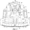
- a pair of drive motors 125 are mounted at the lateral sides of each arm 121 and are orientated to be approximately parallel with the rotational axis of each respective cutting head 128 as shown in figure 7 .
- Each arm 121 further comprise an internal drive and gear assembly 124 coupled to a gear box 126 mounted at one end of each of the drive motors 125.
- Each cutting head 128 is driveably coupled to the drive motors 125 via the respective gear assembly 124 to provide rotation of cutting head 128 about axis 402.
- each arm 121 is coupled to a respective motor unit 130 mounted at a forward end of sled 104.
- Each planetary gear 122 is centred on a pivot rod 405 having a pivot axis 401 referring to figure 4 .
- Each axis 401 is aligned to be generally horizontal when apparatus 100 is positioned on horizontal ground.
- each arm 121 is configured to pivot (relative to each support 120, sled 104 and main frame 102) in the upward and downward direction (vertical plane) by actuation of each motor unit 130.
- each cutting head 128 and in particular the roller cutters 127 may be raised and lowered along the arcuate path 602 referring to figure 6 .
- each arm 121, head 128 and roller cutters 127 may be pivoted between a lowermost position 601 and an uppermost raised position 600 with an angle between positions 600, 601 being approximately 150°.
- each roller cutter 127 and in particular head 128 is suspended in a declined orientation such that a forwardmost roller cutter 127 is positioned lower than a rearwardmost roller cutter 127.
- this angle of declination is 10°. This is advantageous to engage the cutters 127 into the rock face at the desired attack angle to create the initial groove or channel during a first stage of the undercutting operation.
- the extensive range of movement of the cutting heads 128 over the rock face is possible due, in part, to axis 401 being separated and positioned forward relative to axis 400 by a distance corresponding to a length of each support 120.
- each support pivot axis 400 is aligned generally perpendicular to each arm pivot axis 401. Additionally, a rotational axis 402 of each cutting head 128 is orientated generally perpendicular to each arm pivot axis 401. A corresponding rotational axis 403 of each roller cutter 127 is angularly disposed relative to cutting head axis 402 so as to taper outwardly in the downward direction. In particular, each roller cutter axis 403 is orientated to be aligned closer to the orientation of each cutting head rotational axis 402 and support pivot axis 400 relative to the generally perpendicular arm rotational axis 401.
- each support 120 is configured to slew laterally outward in a horizontal plane about each support axis 400 between the extreme inner and positions 501, 502.
- each respective arm 121 is configured to pivot in the upward and downward direction about arm pivot axis 401 to raise and lower the roller cutters 127 between the extreme positions 600, 601.
- a gathering head 129 is mounted at main frame forward end 303 immediately rearward behind each cutting head 128. Gathering head 129 comprises a conventional shape and configuration having side loading aprons and a generally inclined upward facing material contact face to receive and guide cut material rearwardly from the cutting face (and cutting heads 128). Apparatus 100 further comprises a first conveyor 202 extending lengthwise from gathering head 129 to project rearwardly from frame rearward end 304. Accordingly, material cut from the face is gathered by head 129 and transported rearwardly along apparatus 100.
- Control unit 111 comprises a personnel cabin 110 (to be occupied by an operator).
- Unit 111 further comprises an electric and hydraulic power pack 114 to control the various hydraulic and electrical components of apparatus 100 associated with the pivoting movement of supports 120 and arms 121 in addition to the sliding movement of sled 104 and the rotational drive of cutting heads 128.
- Control unit 101 further comprises a second conveyor 112 extending generally lengthwise along the unit 101 and coupled at its forwardmost end to the rearwardmost end of first conveyor 202.
- Unit 101 further comprises a discharge conveyor 113 projecting rearwardly from the rearward end of second conveyor 112 at an upward declined angle. Accordingly, cut material is capable of being transported rearwardly from cutting heads 128 along conveyors 202, 112 and 113 to be received by a truck or other transportation vehicle.
- apparatus 100 is wedged between the tunnel floor and roof via jacking legs 106, 115 and roof grippers 105.
- Sled 104 may then be displaced in a forward direction relative to main frame 102 to engage roller cutters 127 onto the rock face.
- Cutting heads 128 are rotated via motors 125 that create the initial groove or channel in the rock face at a lowermost position.
- a first arm 121 is then pivoted about axis 401 via motor 130 to raise roller cutters 127 along path 602 to achieve the second stage undercutting operation.
- the first support 120 may then be slewed in the lateral sideways direction via pivoting about axis 400 and combined with the raising and lowering rotation of roller cutters 127 creates a depression or pocket within the rock immediately forward of the first arm 121 and support 120.
- the second arm 121 and associated head 128 and cutters 127 are then actuated according to the operation of the first arm 121 involving pivoting in both the vertical and horizontal planes. This sequential dual pivoting movement of the second arm 121 is independent of the initial dual pivoting movement of the first arm 121.
- a phasing and sequencing of the pivoting of arms 121 about axes 401 and supports 120 about axes 400 is controlled via control unit 111.
- jacking legs 106, 115 are retracted to engage tracks 103 onto the ground.
- Tracks 103 are orientated to be generally declined (at an angle of approximately 10° relative to the floor) such that when ground contact is made, the roller cutters 127 are raised vertically so as to clear the tunnel floor.
- the apparatus 100 may then be advanced forward via tracks 103.
- Jacking legs 106, 115 may then be actuated again to raise tracks 103 off the grounds and grippers 105 moved into contact with the tunnel roof to repeat the cutting cycle.
- a forwardmost roof gripper 108 is mounted above sled 104 to stabilise the apparatus 100 when sled 104 is advanced in the forward direction via linear actuating cylinder 201.
- Figure 8 shows the support 120 and one of the arms 121 in an angled position. Arm 121 is pivoted about arm pivot axis 401 such that a cutting head 128 (cf. figure 4 ) would be facing downwards.
- the view shown in figure 8 shows the exterior of the drive train 123.
- the drive train 123 is actuated by a first drive motor 130' and a second drive motor 130", both of which form the drive motor unit 130 ( figure 4 ).
- both the first and second drive motors 130', 130" are hydraulic motors identically built.
- the first drive motor 130' is coupled for torque transmission to an auger drive 132.
- the auger drive 132 forms a first stage of the drive train 123.
- the second drive motor 130" is coupled for torque transmission to a planetary drive 122 ( figure 10 ).
- the planetary drive 122 forms a second stage of the drive train 123.
- the first stage of drive train 123 is engaged by a first brake 131' which might for example be coupled inbetween the first drive motor 130' and the auger drive 132.
- the first brake 131' is a disc brake.
- the cutting apparatus further comprises a second brake 131" adapted to engage the second stage of the drive train 123, e.g. the first hollow wheel 139.
- the arm pivot axis 401 is substantially perpendicular to the support axis 400.
- Figure 10 provides more detailed information regarding the functioning principle of the drive train 123, in particular regarding the second stage (the planetary drive 122).
- Support 121 shall be assumed as stationary for the following description.
- the auger drive 132 is actuated by the first drive motor 130'.
- the first drive motor 130' actuates an auger 133 which engages an auger wheel 134.
- the auger wheel 134 is mounted for torque transmission to a shaft carrying a sun wheel 135.
- the sun wheel 135 is the input element for the planetary drive 122.
- the sun wheel 135 engages a number of planetary wheels 137 which are held by planetary carriers 138.
- the planetary wheels 137 furthermore engage a first hollow wheel 139.
- the planetary carriers 138 are engagingly coupled with a shaft carrying a second sun wheel 141.
- the second sun wheel 141 is the input element to a Wolfrom type drive.
- the second sun wheel 141 engages a number of planetary wheels 143 which are held by corresponding planetary carriers 144.
- the planetary wheels 143 engage a second hollow wheel 145 and an adjacently situated third hollow wheel 147.
- the second and third hollow wheels 145, 147 have an identical module corresponding to the module of the planetary wheels 143, but differ in their number of teeth.
- the second hollow wheel 145 is fixedly attached to the support 120, whereas the third hollow wheel 147 is fixedly attached to the arm 121 for torque transmission to the latter.
- the arm 121 is rotatably supported against the support 120 by way of a multi-row roller bearings 149 which preferably comprises two or more four-point bearing rows. Due to the difference in teeth between the second and third hollow wheel 145, 147, the third hollow wheel 147 rotates very slowly with respect to the second hollow wheel 145, driven by the rotation of the planetary carriers 144 and planetary wheels 143. The third hollow wheel 147 thus is the power output element of the drive train 123.
- the planetary wheels 143 of the Wolfrom type drive are supported by a number of multi-rowed self-alining bearings, such as spherical roller bearings 151.
- the first hollow wheel 139 of the planetary drive 122 is immobilized by the second brake 131", while the first drive motor 130' drives the auger drive 132.
- the resulting transmission ratio hence is a mulitiplication of the individual transmission ratios of the auger drive 132 and the planetary drive 122.
- the first drive motor 130' When executing a second operational mode, preferably the first drive motor 130' is deactived and/or the movement of the auger drive 132 is prevented by the first brake 131', while the second drive motor 130" causes rotation of the first hollow wheel 139 of the planetary drive 122 while the second brake 131" is deactivated.
- the first sun wheel 135 is standing still, and the planetary carriers 138 are rotated via the revolving action of the first hollow wheel 139.
- the overall transmission ratio of the drive train 123 does no longer include the transmission ratio of the auger drive 132. Consequently, the overall transmission ratio is reduced with respect to the first operating mode. This leads to comparatively higher velocity of the third hollow wheel 147, i.e. of the arm 121 with respect to the support 120, while the torque transmitted by the third hollow wheel 147 is lower than in the first operational mode.
- the drive train 123 in all is extremely compact and robust in design while at the same time allowing for flexible control and immense transmission ratios.
- each stage of the planetary drive 122 comprises three planetary wheels.
Description
- The present invention relates to rock cutting apparatus suitable for creating tunnels or subterranean roadways and in particular, although not exclusively, to undercutting apparatus in which at least one rotating head, preferably a plurality of rotating heads are capable of being slewed laterally outward and raised in the upward and downward direction during forward cutting.
- A variety of different types of excavation machines have been developed for cutting drifts, tunnels, subterranean roadways and the like in which a rotatable head is mounted on an arm that is in turn movably mounted at a main frame so as to create a desired tunnel cross sectional profile.
WO2012/156841 ,WO 2012/156842 ,WO 2010/050872 ,WO 2012/156884 ,WO2011/093777 ,DE 20 2111 050 143 U1 . All described apparatus for mill cutting of rock and minerals in which a rotating cutting head forced into contact with the rock face as supported by a movable arm. In particular,WO 2012/156884 describes the cutting end of the machine in which the rotatable heads are capable of being raised and lowered vertically and deflecting in the lateral sideways direction by a small angle in an attempt to try enhance the cutting action. -
CN103924970 discloses a two-arm coal mining machine, comprising a traction part, a motor, a drive part, rocker arms and a height-regulating device. The motor is connected with the drive part and used for supplying power. The drive part is connected with the first rocker arm and the second rocker arm, and each rocker arm is connected with two sets of rollers. -
GB2060794 -
GB2124407 -
WO 2014/090589 describes a machine for digging roadways tunnels and the like in which a plurality of cutting heads are movable to dig into the rock face via a pivoting arcuate cutting path.US 2003/0230925 describes a rock excavator having a cutter head mounting a plurality of annular disc cutters suitable to operate in an undercutting mode. - It has been observed that during the slewing operation of the at least one arm, significant torque needs to be transmitted in particular when operating in undercutting mode.
- Mechanisms which allow for high torque transmission however entail the drawback of very low transmission speeds, thus limiting the overall mine development progress.
- Furthermore, it has been observed that due to specific geophysical attributes of the mining sites at different locations, the mining equipment, in particular rock cutting apparatus, needs to be specifically customized in order to ideally cope with the working environment. It has been found in conventional systems that the design and modification of existing mining equipment for adapting the equipment to the regional environment is time consuming and costly.
- Furthermore, it has been observed that conventional cutting machines are not optimised to cut hard rock having a strength typically beyond 120 MPa whilst creating a tunnel or subterranean cavity safely and reliably of desired cross sectional configuration. Accordingly, what is required is a cutting machine that addresses these problems.
- It is an objective of the present invention to provide a cutting apparatus which allows for reliable torque transmission, in particular for undercutting operation of the cutting head while at the same time allowing for time-efficient, rapid mine development.
- It is a further objective of the present invention to provide a cutting machine suitable to form tunnels and subterranean roadways being specifically configured to cut hard rock beyond 120 MPa in a controlled and reliable manner. It is a further specific objective to provide a cutting machine capable of creating a tunnel with a variable cross sectional area within a maximum and a minimum cutting range. It is a further specific objective to provide a cutting (excavator) machine operable in an 'undercutting' mode according to a two stage cutting action.
- According to a first aspect of the present invention there is provided a cutting apparatus for creating tunnels or subterranean roadways and the like comprising: at least one arm pivotally mounted to the apparatus and adapted to pivot in an upward and downward direction; at least one arm actuator to actuate pivoting movement of the at least one arm; a rotatable cutting head mounted at the at least one arm; wherein the actuator comprises a drive motor unit and a drive train coupled to the drive motor unit, the drive motor unit and drive train being configured for selective operation in one of: a first operating mode in which a first pivoting velocity and first torque are transmitted to the at least one arm, or a second operating mode in which a second velocity and second torque are transmitted to the at least one arm, the first velocity being lower than the second velocity and the first torque being higher than the second torque; wherein the drive motor unit comprises a first drive motor and a second drive motor, the first drive motor applying torque to the drive train in the first operating mode, and the second drive motor applying torque to the drive train in the second operating mode. Further, the drive train comprises an auger drive and a planetary drive coupled to one another in series. The aforementioned solution provides the following benefits: By splitting up the mechanism into a first operating mode and a second operating mode, it becomes possible to unify the advantages of two otherwise contradicting goals; The first operating mode provides for higher torque at lower velocities, while the second operating mode provides for higher velocity at lower torque. With a single operation mode, it may be possible to operate at different velocities. However, the torque which is defined by the drive train would then limit the maximum velocity range achievable by the mechanism. According to the invention, it is possible to deliberately switch between the first and second operation mode such that when arm movement at higher speeds is required, the second operation mode can be used. By providing a lower amount of torque therewith, the drive train automatically operates at higher speeds.
- The combination of auger drive and planetary drive coupled to one another in series provides for a very robust drive train which is able to generate very high reduction ratios. It also allows for very compact overall design in relation to the achievable reduction ratio. In general, the rock cutting apparatus can easily be adapted regarding its two operating modes by substituting the auger drive and for planetary drive with a differently dimensioned alternative. Thus different transmission ratios can be installed easily.
- The auger drive preferably comprises an auger and an auger wheel which are in engagement with each other. The auger wheel preferably is the input element of the drive train, and the auger wheel preferably is coupled to an input shaft of the planetary drive, i.e. coupled to the sun wheel of the planetary drive.
- Preferably, the first operation mode is used for upward movement of the arm, i.e. for rock cutting, particularly undercutting. The second operation mode preferably is used for moving the arm downwards, such as after completing a cutting movement and prior to moving the machine into the next cutting position. By lowering the torque for the second operational mode relative to the first mode, arm movement becomes potentially less dangerous with regard to possible collateral damage to machinery or personnel standing near the arm. By using two individual drive motors for the first and second operation modes, control of the cutting apparatuses operating modes becomes particularly easy to handle.
- Preferentially, the planetary drive has a first stage planetary drive, the drive train further comprising at least a second stage planetary drive coupled in series to the first stage planetary drive. By coupling two planetary drives in series to one another, even greater transmission ratios are achievable while consuming very little space in the axial dimension of the drive train. Preferably, the first stage planetary drive comprises a first sun wheel, a number of planetary wheels engaged by the sun wheel, a first planetary carrier coupled to the planetary wheels and a first hollow wheel engaged by the planetary wheels. It is further preferred if the first planetary carrier is coupled to a second sun wheel (pertaining to the second stage planetary drive). The second stage planetary preferably drive further comprises a number of planetary carriers carrying planetary wheels and a second hollow wheel being engaged by the planetary wheels. Furthermore, the second stage planetary drive preferably comprises a third hollow wheel engaged by the planetary wheels of the second stage planetary drive.
- In a particularly preferred alternative embodiment, the second stage planetary drive is a Wolfrom type drive. The Wolfrom type drive qualifies as a high reduction type gear box and preferably comprises two hollow wheels, one of which is fixed to the rock cutting apparatus. The planetary wheels of the second stage planetary drive engage both hollow wheels. Both hollow wheels of the Wolfrom type drive have an identical module, but differing teeth numbers. Consequently, after the planetary carrier driven by the planetary wheels has performed one full revolution, the second hollow wheel has moved by a very small amount, namely the differing number in teeth, with respect to the fixed hollow wheel. The result is an extreme transmission ratio which is particularly beneficial for the intended use of the cutting apparatus according to the invention.
- As a mechanically less complex alternative to the Wolfrom type drive, which is also easier to calculate, it is alternatively preferred if the drive train comprises a third stage planetary drive coupled in series to the second stage planetary drive. While requiring larger axial dimensions for the drive train, it is still possible to create satisfactory transmission ratios with this alternative solution.
- According to a further preferred embodiment, the auger drive comprises an auger, and the first drive motor is coupled to the auger. It is further preferred if the planetary drive comprises a first hollow gear, and the second drive motor is coupled to the first hollow gear. By making the first drive motor engage the first stage of the drive train, while the second drive motor engages the second stage of the drive train, it becomes particularly easy to define distinct operating modes with well defined transmission ratios and thus well defined sets of velocity and torque, respectively. By selectively operating the first drive motor or the second drive motor, the power transmission is initiated upstream of the auger drive, thus using the entire reduction ratio of the first and second stages. A selective operation of only the second drive motor presents a convenient bypass of the first stage of the drive train. Instead, the first hollow gear is then directly driven by the second drive motor to initiate torque transmission through the second stage of the drive train.
- According to a further preferred embodiment, the apparatus comprises a first brake configured to prevent any torque transmission from the first drive motor to the arm. Further, it is preferred if the cutting apparatus comprises a second brake configured to prevent any torque transmission from the second drive motor to the arm.
- Selective braking of the respective inactive drive motor ensures that in each operating mode, the arm is actuated at the appropriate velocity and torque which is predefined by the two stages of the drive train and the drive motors. The brakes preferably operate by immobilizing the auger and/or auger wheel of the auger drive (first brake), or by immobilizing the first hollow gear (second brake).
- Preferably, the drive train comprises a second hollow wheel and a third hollow wheel, both associated with the second stage planetary drive, wherein the second and third hollow wheel have an identical gear module, and the number of teeth of the second hollow wheel differs from the number of teeth of the third hollow wheel. The difference in teeth preferably is in the two-digit range or less, preferably in the one-digit range, and particularly preferred between 1 and 5.
- The above-mentioned preferred embodiments allow for a wide range of transmission ratios.
- In particularly preferred embodiments, in the first operating mode, the gear transmission ratio of the drive train is in the range of 5,000 to 10,000, preferably 7,000 to 9,000, and most preferably 8,000; and/or in the second operating mode, the gear transmission ratio of the drive train is in the range of 500 to 2,000, preferably 700 to 1,200, and most preferably 850. The aforementioned ranges of transmission ratios provide a surprisingly good balance of velocity and torque for the intended purposes of actuating the arms for cutting operation and repositioning the arms prior to machine movement.
- It is particularly preferred for the cutting apparatus if the first and second drive motors are hydraulic motors, and preferably are identical motors. Under "identical" it shall be understood that the motors at least have substantially the same nominal power output. Preferably, identical shall be understood to mean that the motors are of identical build, thus reducing part complexity of the entire cutting apparatus and also facilitating motor control programming.
- Preferably, the cutting apparatus of the invention further comprises a rotatable cutting head mounted at the at least one arm, the head being rotatable about a head axis orientated to extend substantially transverse to the arm pivot axis,
- In a further aspect, the invention achieves its objective by suggesting a cutting apparatus comprising at least one arm rotatably mounted to a support and driven by an arm actuator, the arm actuator comprising a drive train, said drive train having at least a first stage and a second stage planetary drive coupled to one another in series, with a first hollow wheel being mounted on the support, and a second hollow wheel being coupled to the arm, such that the support and the arm are rotatable with respect to one another. Preferably, the first and second stage planetary drives constitute a Wolfrom gear. The mining apparatus of this aspect preferably is enhanced in accordance with any combination of features of the preferred embodiments described hereinabove and hereinbelow.
- For practical purposes, while perfectly well possible to operate with one arm only, it is preferred if the cutting apparatus according to anyone of the aforementioned preferred embodiments further comprises two individually actuatable arms. The general concept and benefits of these two individually operable arms are elucidated further herein below.
- Preferably, the cutting apparatus thus further comprises: a second arm pivotally mounted to the apparatus, the first and second arm being adapted to pivot independently of one another in an upward and downward direction; comprising for each arm an arm actuator to actuate independently the pivoting movement of the first and second arms; a rotatable cutting head mounted at each of the first and second arms, each head rotatable about a head axis oriented to extend substantially transverse to each respective arm pivot axis. Preferably, the cutting apparatus comprises a main frame having generally upward, downward and side facing regions; a first and second support pivotally mounted relative to the main frame via respective first and second support axes aligned generally upright relative to the upward and downward facing regions such that each first and second support is configured to pivot laterally in a sideways direction relative to the side facing regions; at least one first and second support actuator to respectively actuate independently movement of each of the first and second supports relative to the main frame; wherein the first and second arms are each pivotally mounted to the respective first and second support via a respective arm pivot axis aligned in a direction extending transverse including perpendicular to each support pivot axis to enable the first and second arms to pivot independently of one another and to pivot relative to each of the respective first and second supports in an upward and downward direction relative to the upward and downward facing regions; and wherein the at least one first and second arm actuators are adapted to actuate independently the pivoting movement of the first and second arms relative to each of the respective first and second support.
- The further objectives are achieved by providing a cutting apparatus having a plurality of rotatably mounted cutting heads that may be pivoted in an upward and downward direction and a lateral side-to-side direction via a plurality of independently pivoting booms mounted at a main frame. In particular, each boom comprises a support pivotally mounted to the main frame and carrying an arm via a respective additional pivot mounting such that each cutting head is capable of pivoting about two pivoting axes. The desired range of movement of each head is provided as the dual pivoting axes are aligned transverse (including perpendicular) to one another and are spaced apart in the longitudinal direction of the apparatus between a forward and rearward end.
- Advantageously, the cutting heads comprise a plurality of disc-like roller cutters distributed circumferentially around a perimeter of each head so as to create a groove or channel into the rock face as the heads are driven about their respective rotational axes. The heads may then be raised vertically so as to overcome the relatively low tensile strength of the overhanging rock to provide breakage via force and energy that is appreciably lower than a more common compressive cutting action provided by cutting picks and the like.
- A specific implementation of the present invention will now be described, by way of example only, and with reference to the accompanying drawings in which:
-
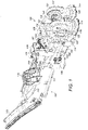
Figure 1 is a front perspective view of a mobile cutting apparatus suitable for creating tunnels or subterranean roadways having a forward mounted cutting unit and a rearward control unit according to a specific implementation of the present invention; -
Figure 2 is a rear perspective view of the cutting apparatus offigure 1 ; -
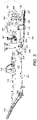
Figure 3 is a side elevation view of the apparatus offigure 2 ; -
Figure 4 is a magnified front perspective view of the cutting unit of the apparatus offigure 3 ; -
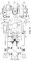
Figure 5 is a plan view of the cutting apparatus offigure 4 ; -
Figure 6 is a side elevation view of the cutting apparatus offigure 5 ; -
Figure 7 is a front end view of the cutting apparatus offigure 6 ; -
Figure 8 shows a partial side view of the cutting apparatus of the cutting apparatus of the previous figures; -
Figure 9 is a top view projection of the cutting apparatus according tofigure 8 ; and -
Figure 10 is a cross-sectional view in plan A-A shown infigure 8 . - Referring to
figure 1 , cuttingapparatus 100 comprises amain frame 102 mounting a plurality of cutting components configured to cut into a rock or mineral face to create tunnels or subterranean roadways.Apparatus 100 is configured specifically for operation in an undercutting mode in which a plurality ofrotatable roller cutters 127 may be forced into the rock to create a groove or channel and then to be pivoted vertically upward so as to overcome the reduced tensile force immediately above the groove or channel and break the rock. Accordingly, the present cutting apparatus is optimised for forward advancement into the rock or mineral utilising less force and energy typically required for conventional compression type cutters that utilise cutting bits or picks mounted at rotatable heads. However, the present apparatus may be configured with different types of cutting head to those described herein including in particular pick or bit type cutting heads in which each pick is angularly orientated at the cutting head to provide a predetermined cutting attack angle. - Referring to
figures 1 to 3 ,main frame 102 compriseslateral sides 302 to be orientated towards the wall of the tunnel; an upward facing region 300 to be orientated towards a roof of the tunnel; a downward facingregion 301 orientated to be facing the floor of the tunnel; a forward facingend 303 intended to be positioned facing the cutting face and a rearward facingend 304 intended to be positioned facing away from the cutting face. - An
undercarriage 109 is mounted generally belowmain frame 102 and in turn mounts a pair ofcrawler tracks 103 driven by a hydraulic (or electric) motor to provide forward and rearward movement ofapparatus 100 over the ground when in a non-cutting mode. A pair of rear ground engaging jackinglegs 106 are mounted atframe sides 302 towardsrearward end 304 and are configured to extend and retract linearly relative toframe 102.Frame 102 further comprises a forward pair of jackinglegs 115 also mounted at eachframe side 302 and towardsforward end 303 and being configured to extend and retract to engage the floor tunnel. By actuation oflegs main frame 102 and inparticular tracks 103 may be raised and lowered in the upward and downward direction so as to suspendtracks 103 off the ground toposition apparatus 100 in a cutting mode. A pair ofroof engaging grippers 105 project upwardly frommain frame 102 at frame rearwardend 304 and are extendable and retractable linearly in the upward and downward direction viacontrol cylinders 116.Grippers 105 are therefore configured to be raised into contact with the tunnel roof and in extendable combination with jackinglegs apparatus 100 in a stationary position between the tunnel floor and roof when in the cutting mode. - A
sled 104 is slidably mounted on top ofmain frame 102 via aslide mechanism 203.Sled 104 is coupled to a linearhydraulic cylinder 201 such that by reciprocating extension and retraction ofcylinder 201,sled 104 is configured slide linearly between frame forward and rearward ends 303, 304. - A pair of hydraulically actuated bolting
units 107 are mounted atmain frame 102 betweensled 104 androof gripping unit units 107 are configured to secure a mesh structure (not shown) to the roof of the tunnel asapparatus 100 is advanced in a forward cutting direction.Apparatus 100 also comprises a mesh support structure (not shown) mounted generally abovesled 104 so as to positionally support the mesh directly below the roof prior to bolting into position. - A pair of
supports 120 are pivotally mounted at and project forwardly fromsled 104 immediately above frameforward end 303.Supports 120 are generally spaced apart in a lateral widthwise direction of theapparatus 100 and are configured to independently pivot laterally outward from one another relative tosled 104 andmain frame 102. Eachsupport 120 comprises aforward end 503 and arearward end 504 referring tofigure 5 . Afirst mount flange 118 is provided at support rearwardend 504 being generally rearward facing. - A corresponding
second mount flange 119 projects laterally outward from a side ofsled 104 immediately behind thefirst flange 118. A pair of linearhydraulic cylinders 117 are mounted to extend betweenflanges support 120 is configured to pivot in the generally horizontal plane and in the lateral sideways direction relative to framesides 302. Referring to figured 4, eachsupport 120 is mounted atsled 104 via apivot rod 404 extending generally vertically (whenapparatus 100 is positioned on horizontal ground) throughsled 104 and being suspended generally above the main frameforward end 303. Eachsupport 120 is therefore configured to pivot or slew aboutpivot axis 400. Referring tofigure 5 , eachsupport 120 is further coupled to a respective innerhydraulic cylinder 500 mounted at an inner region ofsled 104 to cooperate with side mountedcylinders 117 to laterally slew eachsupport 120 aboutpivot axis 400. - Referring to
figures 4 and5 , as the respective pivot axes 400 are space apart in the widthwise direction ofapparatus 100, supports 120 are capable of being slewed inwardly to a maximuminward position 501 and to be slewed laterally outward to a maximumoutward position 502. According to the specific implementation, an angle between the inner andouter slewing positions - Referring to
figures 1 to 3 , anarm 121 is pivotally mounted generally at theforward end 503 of eachsupport 120. Eacharm 121 comprises a cuttinghead 128 rotatably mounted at a distal end. Each cuttinghead 128 comprises a disk like (generally cylindrical) configuration. The plurality of generally annular or disc shapedroller cutters 127 are mounted at the circumferential perimeter of eachhead 128 and comprise a sharp annular cutting edge configured specifically for undercutting the rock.Cutters 127 are rotatably mounted independently relative to one another andhead 128 and are generally free to rotate about their own axis. Eachroller cutter 127 projects axially beyond a forwardmost annular edge ofhead 128 such that whenarms 121 are orientated to be extending generally downward,roller cutters 127 represent a lowermost part of theentire head 128 andarm 121 assembly. Eacharm 121 may be considered to comprise a length such thatarm 121 is mounted at eachrespective support 120 at or towards a proximal arm end and to mount eachhead 128 at a distal arm end. In particular, eacharm 121 comprises an internally mounted planetary drive indicated generally bereference 122.Planetary drive 122 preferably comprises a Wolfrom type drive and is coupled to adrive motor unit 130 via a drive train indicated generally byreference 123. A pair ofdrive motors 125 are mounted at the lateral sides of eacharm 121 and are orientated to be approximately parallel with the rotational axis of eachrespective cutting head 128 as shown infigure 7 . Eacharm 121 further comprise an internal drive andgear assembly 124 coupled to agear box 126 mounted at one end of each of thedrive motors 125. Each cuttinghead 128 is driveably coupled to thedrive motors 125 via therespective gear assembly 124 to provide rotation of cuttinghead 128 aboutaxis 402. - According to the specific implementation, and as shown in
figure 7 , eacharm 121 is coupled to arespective motor unit 130 mounted at a forward end ofsled 104. Eachplanetary gear 122 is centred on apivot rod 405 having apivot axis 401 referring tofigure 4 . Eachaxis 401 is aligned to be generally horizontal whenapparatus 100 is positioned on horizontal ground. Accordingly, eacharm 121 is configured to pivot (relative to eachsupport 120,sled 104 and main frame 102) in the upward and downward direction (vertical plane) by actuation of eachmotor unit 130. As such, each cuttinghead 128 and in particular theroller cutters 127 may be raised and lowered along thearcuate path 602 referring tofigure 6 . In particular, eacharm 121,head 128 androller cutters 127 may be pivoted between alowermost position 601 and an uppermost raisedposition 600 with an angle betweenpositions lowermost position 601, eachroller cutter 127 and inparticular head 128 is suspended in a declined orientation such that aforwardmost roller cutter 127 is positioned lower than arearwardmost roller cutter 127. According to the specific implementation, this angle of declination is 10°. This is advantageous to engage thecutters 127 into the rock face at the desired attack angle to create the initial groove or channel during a first stage of the undercutting operation. Additionally, the extensive range of movement of the cutting heads 128 over the rock face is possible due, in part, toaxis 401 being separated and positioned forward relative toaxis 400 by a distance corresponding to a length of eachsupport 120. - Referring to
figure 4 , eachsupport pivot axis 400 is aligned generally perpendicular to eacharm pivot axis 401. Additionally, arotational axis 402 of each cuttinghead 128 is orientated generally perpendicular to eacharm pivot axis 401. A correspondingrotational axis 403 of eachroller cutter 127 is angularly disposed relative to cuttinghead axis 402 so as to taper outwardly in the downward direction. In particular, eachroller cutter axis 403 is orientated to be aligned closer to the orientation of each cutting headrotational axis 402 andsupport pivot axis 400 relative to the generally perpendicular armrotational axis 401. - Accordingly, each
support 120 is configured to slew laterally outward in a horizontal plane about eachsupport axis 400 between the extreme inner andpositions figure 6 , eachrespective arm 121 is configured to pivot in the upward and downward direction aboutarm pivot axis 401 to raise and lower theroller cutters 127 between theextreme positions - A
gathering head 129 is mounted at main frame forward end 303 immediately rearward behind each cuttinghead 128.Gathering head 129 comprises a conventional shape and configuration having side loading aprons and a generally inclined upward facing material contact face to receive and guide cut material rearwardly from the cutting face (and cutting heads 128).Apparatus 100 further comprises afirst conveyor 202 extending lengthwise from gatheringhead 129 to project rearwardly from frame rearwardend 304. Accordingly, material cut from the face is gathered byhead 129 and transported rearwardly alongapparatus 100. - Referring to
figures 1 to 3 , adetachable control unit 101 is mounted to the frame rearward end 403 via apivot coupling 200.Control unit 111 comprises a personnel cabin 110 (to be occupied by an operator).Unit 111 further comprises an electric andhydraulic power pack 114 to control the various hydraulic and electrical components ofapparatus 100 associated with the pivoting movement ofsupports 120 andarms 121 in addition to the sliding movement ofsled 104 and the rotational drive of cutting heads 128. -
Control unit 101 further comprises asecond conveyor 112 extending generally lengthwise along theunit 101 and coupled at its forwardmost end to the rearwardmost end offirst conveyor 202.Unit 101 further comprises adischarge conveyor 113 projecting rearwardly from the rearward end ofsecond conveyor 112 at an upward declined angle. Accordingly, cut material is capable of being transported rearwardly from cuttingheads 128 alongconveyors - In use,
apparatus 100 is wedged between the tunnel floor and roof via jackinglegs roof grippers 105.Sled 104 may then be displaced in a forward direction relative tomain frame 102 to engageroller cutters 127 onto the rock face. Cutting heads 128 are rotated viamotors 125 that create the initial groove or channel in the rock face at a lowermost position. Afirst arm 121 is then pivoted aboutaxis 401 viamotor 130 to raiseroller cutters 127 alongpath 602 to achieve the second stage undercutting operation. Thefirst support 120 may then be slewed in the lateral sideways direction via pivoting aboutaxis 400 and combined with the raising and lowering rotation ofroller cutters 127 creates a depression or pocket within the rock immediately forward of thefirst arm 121 andsupport 120. Thesecond arm 121 and associatedhead 128 andcutters 127 are then actuated according to the operation of thefirst arm 121 involving pivoting in both the vertical and horizontal planes. This sequential dual pivoting movement of thesecond arm 121 is independent of the initial dual pivoting movement of thefirst arm 121. A phasing and sequencing of the pivoting ofarms 121 aboutaxes 401 and supports 120 aboutaxes 400 is controlled viacontrol unit 111. - When the maximum forward travel of
sled 104 is achieved, jackinglegs tracks 103 onto the ground.Tracks 103 are orientated to be generally declined (at an angle of approximately 10° relative to the floor) such that when ground contact is made, theroller cutters 127 are raised vertically so as to clear the tunnel floor. Theapparatus 100 may then be advanced forward via tracks 103. Jackinglegs tracks 103 off the grounds andgrippers 105 moved into contact with the tunnel roof to repeat the cutting cycle. Aforwardmost roof gripper 108 is mounted abovesled 104 to stabilise theapparatus 100 whensled 104 is advanced in the forward direction vialinear actuating cylinder 201. -
Figure 8 shows thesupport 120 and one of thearms 121 in an angled position.Arm 121 is pivoted aboutarm pivot axis 401 such that a cutting head 128 (cf.figure 4 ) would be facing downwards. The view shown infigure 8 shows the exterior of thedrive train 123. Thedrive train 123 is actuated by a first drive motor 130' and asecond drive motor 130", both of which form the drive motor unit 130 (figure 4 ). Preferably, both the first andsecond drive motors 130', 130" are hydraulic motors identically built. The first drive motor 130' is coupled for torque transmission to anauger drive 132. The auger drive 132 forms a first stage of thedrive train 123. Thesecond drive motor 130" is coupled for torque transmission to a planetary drive 122 (figure 10 ). Theplanetary drive 122 forms a second stage of thedrive train 123. - The first stage of
drive train 123 is engaged by a first brake 131' which might for example be coupled inbetween the first drive motor 130' and theauger drive 132. Preferably, the first brake 131' is a disc brake. - The cutting apparatus further comprises a
second brake 131" adapted to engage the second stage of thedrive train 123, e.g. the firsthollow wheel 139. - As can be seen from
figure 9 , thearm pivot axis 401 is substantially perpendicular to thesupport axis 400. -
Figure 10 provides more detailed information regarding the functioning principle of thedrive train 123, in particular regarding the second stage (the planetary drive 122).Support 121 shall be assumed as stationary for the following description. For pivotingarm 121 relative to support 120 in a first operational mode, theauger drive 132 is actuated by the first drive motor 130'. The first drive motor 130' actuates anauger 133 which engages anauger wheel 134. Theauger wheel 134 is mounted for torque transmission to a shaft carrying asun wheel 135. Thesun wheel 135 is the input element for theplanetary drive 122. Thesun wheel 135 engages a number ofplanetary wheels 137 which are held byplanetary carriers 138. Theplanetary wheels 137 furthermore engage a firsthollow wheel 139. - The
planetary carriers 138 are engagingly coupled with a shaft carrying asecond sun wheel 141. Thesecond sun wheel 141 is the input element to a Wolfrom type drive. Thesecond sun wheel 141 engages a number ofplanetary wheels 143 which are held by correspondingplanetary carriers 144. Theplanetary wheels 143 engage a secondhollow wheel 145 and an adjacently situated thirdhollow wheel 147. The second and thirdhollow wheels planetary wheels 143, but differ in their number of teeth. The secondhollow wheel 145 is fixedly attached to thesupport 120, whereas the thirdhollow wheel 147 is fixedly attached to thearm 121 for torque transmission to the latter. Thearm 121 is rotatably supported against thesupport 120 by way of amulti-row roller bearings 149 which preferably comprises two or more four-point bearing rows. Due to the difference in teeth between the second and thirdhollow wheel hollow wheel 147 rotates very slowly with respect to the secondhollow wheel 145, driven by the rotation of theplanetary carriers 144 andplanetary wheels 143. The thirdhollow wheel 147 thus is the power output element of thedrive train 123. - The
planetary wheels 143 of the Wolfrom type drive are supported by a number of multi-rowed self-alining bearings, such asspherical roller bearings 151. - In operation, for executing a first operational mode, the first
hollow wheel 139 of theplanetary drive 122 is immobilized by thesecond brake 131", while the first drive motor 130' drives theauger drive 132. The resulting transmission ratio hence is a mulitiplication of the individual transmission ratios of theauger drive 132 and theplanetary drive 122. - When executing a second operational mode, preferably the first drive motor 130' is deactived and/or the movement of the
auger drive 132 is prevented by the first brake 131', while thesecond drive motor 130" causes rotation of the firsthollow wheel 139 of theplanetary drive 122 while thesecond brake 131" is deactivated. Now, thefirst sun wheel 135 is standing still, and theplanetary carriers 138 are rotated via the revolving action of the firsthollow wheel 139. Now, the overall transmission ratio of thedrive train 123 does no longer include the transmission ratio of theauger drive 132. Consequently, the overall transmission ratio is reduced with respect to the first operating mode. This leads to comparatively higher velocity of the thirdhollow wheel 147, i.e. of thearm 121 with respect to thesupport 120, while the torque transmitted by the thirdhollow wheel 147 is lower than in the first operational mode. - As is evident from
figure 10 , thedrive train 123 in all is extremely compact and robust in design while at the same time allowing for flexible control and immense transmission ratios. - In preferred embodiments, each stage of the
planetary drive 122 comprises three planetary wheels.
Claims (14)
- Cutting apparatus (100) suitable for creating tunnels or subterranean roadways and the like comprising:at least one arm (121) pivotally mounted to the apparatus and adapted to pivot in an upward and downward direction;at least one arm actuator (122, 130) to actuate pivoting movement of the at least one arm (121);a rotatable cutting head (128) mounted at the at least one arm (121);wherein the actuator (122) comprises:a drive motor unit (130) anda drive train (123) coupled to the drive motor unit,characterized in thatthe drive motor unit and drive train being configured for selective operation in one of:a first operating mode in which a first pivoting velocity and first torque are transmitted to the at least one arm (121), ora second operating mode in which a second velocity and second torque are transmitted to the at least one arm (121),the first velocity being lower than the second velocity and the first torque being higher than the second torque,wherein the drive motor unit comprises a first drive motor (130') and a second drive motor (130"), the first drive motor applying torque to the drive train (123) in the first operating mode, and the second drive motor applying torque to the drive train (123) in the second operating mode,the drive train (123) comprising an auger drive (132) and a planetary drive (122) coupled to one another in series.
- The cutting apparatus of claim 1,
the planetary drive having a first stage planetary drive (135, 137, 139), the drive train further comprising at least a second stage planetary drive (141, 143, 145, 147) coupled in series to the first stage planetary drive. - The cutting apparatus of claim 1 or 2,
the second stage planetary drive being a Wolfrom type drive. - The cutting apparatus of claim 1 or 2,
comprising a third stage planetary drive coupled in series to the second stage planetary drive. - The cutting apparatus of any one of the preceding claims,
wherein the auger drive (132) comprises an auger (133), and the first drive motor (130') is coupled to the auger. - The cutting apparatus of any one of the preceding claims,
wherein the planetary drive (122) comprises a first hollow gear (139), and the second drive motor (130") is coupled to the first hollow gear (139). - The cutting apparatus of any one of the preceding claims,
comprising a first brake (131') configured to prevent any torque transmission from the first drive motor (130') to the arm (121). - The cutting apparatus of any one of the preceding claims, comprising a second brake (131") configured to prevent any torque transmission from the second drive motor (130") to the arm (121).
- The cutting apparatus of any one of the preceding claims,
the drive train (123) comprising a second hollow wheel (145) and a third hollow wheel (147), both associated with the second stage planetary drive, wherein the second and third hollow wheel have an identical gear module, and the number of teeth of the second hollow wheel (145) differs from the number of teeth of the third hollow wheel (147). - The cutting apparatus of claim 9,
wherein the difference in teeth is in the two-digit range or less, preferably in the one-digit range, and particularly preferred between 1 and 5. - The cutting apparatus of any one of the preceding claims,
wherein in the first operating mode, the gear transmission ratio of the drive train (123) is in the range of 5,000 to 10,000, preferably 7,000 to 9,000; and/or in the second operating mode, the gear transmission ratio of the drive train (123) is in the range of 500 to 2,000, preferably 700 to 1,200. - The cutting apparatus of any one of the preceding claims, the first and second drive motors (130',130") being hydraulic motors, and preferably being identical motors.
- The cutting apparatus of any one of the preceding claims, the at least one arm being a first arm, and the apparatus further comprising a second arm (121) pivotally mounted to the apparatus,the first and second arm (121) being adapted to pivot independently of one another in an upward and downward direction;comprising for each arm (121) an arm actuator (122, 130) to actuate independently the pivoting movement of the first and second arms (121);a rotatable cutting head (128) mounted at each of the first and second arms (121), each head (128) rotatable about a head axis (402) orientated to extend substantially transverse to each respective arm pivot axis (401).
- The cutting apparatus of any one of the preceding claims, comprising:a main frame (102) having generally upward (300), downward (301) and side (302) facing regions;a first and second support (120) pivotally mounted relative to the main frame (102) via respective first and second support axes (400) aligned generally upright relative to the upward (300) and downward (301) facing regions such that each first and second support (120) is configured to pivot laterally in a sideways direction relative to the side (302) facing regions;at least one first and second support actuator (117) to respectively actuate independently movement of each of the first and second supports (120) relative to the main frame (102); whereinthe first and second arms (121) are each pivotally mounted to the respective first and second (120) support via a respective arm pivot axis (401) aligned in a direction extending transverse including perpendicular to each support pivot axis (400) to enable the first and second arms (121) to pivot independently of one another and to pivot relative to each of the respective first and second supports (120) in an upward and downward direction relative to the upward (300) and downward (301) facing regions; andwherein the at least one first and second arm actuators (122, 130) are adapted to actuate independently the pivoting movement of the first and second arms (121) relative to each of the respective first and second support (120).
Applications Claiming Priority (2)
| Application Number | Priority Date | Filing Date | Title |
|---|---|---|---|
| PCT/EP2014/071334 WO2016055087A1 (en) | 2014-10-06 | 2014-10-06 | Cutting apparatus |
| PCT/EP2015/072853 WO2016055384A1 (en) | 2014-10-06 | 2015-10-02 | Cutting apparatus |
Publications (2)
| Publication Number | Publication Date |
|---|---|
| EP3204613A1 EP3204613A1 (en) | 2017-08-16 |
| EP3204613B1 true EP3204613B1 (en) | 2022-12-07 |
Family
ID=51663169
Family Applications (8)
| Application Number | Title | Priority Date | Filing Date |
|---|---|---|---|
| EP20184847.0A Withdrawn EP3754156A1 (en) | 2014-10-06 | 2014-10-06 | Cutting apparatus |
| EP14781514.6A Active EP3204607B1 (en) | 2014-10-06 | 2014-10-06 | Cutting apparatus |
| EP15775185.0A Active EP3204613B1 (en) | 2014-10-06 | 2015-10-02 | Cutting apparatus |
| EP15777655.0A Active EP3204609B1 (en) | 2014-10-06 | 2015-10-02 | Device for the installation of rock bolts and cutting apparatus |
| EP15775431.8A Active EP3204608B1 (en) | 2014-10-06 | 2015-10-02 | Cutting apparatus and method of operating |
| EP15771974.1A Active EP3204612B1 (en) | 2014-10-06 | 2015-10-02 | Cutting apparatus using a clearing arrangement |
| EP15781887.3A Active EP3204610B1 (en) | 2014-10-06 | 2015-10-02 | Cutting apparatus and method of operating |
| EP15771662.2A Ceased EP3204611A2 (en) | 2014-10-06 | 2015-10-02 | Cutting apparatus using a plurality of drive motors |
Family Applications Before (2)
| Application Number | Title | Priority Date | Filing Date |
|---|---|---|---|
| EP20184847.0A Withdrawn EP3754156A1 (en) | 2014-10-06 | 2014-10-06 | Cutting apparatus |
| EP14781514.6A Active EP3204607B1 (en) | 2014-10-06 | 2014-10-06 | Cutting apparatus |
Family Applications After (5)
| Application Number | Title | Priority Date | Filing Date |
|---|---|---|---|
| EP15777655.0A Active EP3204609B1 (en) | 2014-10-06 | 2015-10-02 | Device for the installation of rock bolts and cutting apparatus |
| EP15775431.8A Active EP3204608B1 (en) | 2014-10-06 | 2015-10-02 | Cutting apparatus and method of operating |
| EP15771974.1A Active EP3204612B1 (en) | 2014-10-06 | 2015-10-02 | Cutting apparatus using a clearing arrangement |
| EP15781887.3A Active EP3204610B1 (en) | 2014-10-06 | 2015-10-02 | Cutting apparatus and method of operating |
| EP15771662.2A Ceased EP3204611A2 (en) | 2014-10-06 | 2015-10-02 | Cutting apparatus using a plurality of drive motors |
Country Status (14)
| Country | Link |
|---|---|
| US (7) | US10364675B2 (en) |
| EP (8) | EP3754156A1 (en) |
| JP (1) | JP6444498B2 (en) |
| CN (7) | CN106795758B (en) |
| AU (7) | AU2014408540B2 (en) |
| BR (1) | BR112017006811A2 (en) |
| CA (7) | CA2960064C (en) |
| ES (3) | ES2891498T3 (en) |
| FI (2) | FI3204610T3 (en) |
| MX (1) | MX2017004466A (en) |
| PL (5) | PL3204607T3 (en) |
| RU (1) | RU2678294C2 (en) |
| WO (7) | WO2016055087A1 (en) |
| ZA (1) | ZA201701648B (en) |
Families Citing this family (26)
| Publication number | Priority date | Publication date | Assignee | Title |
|---|---|---|---|---|
| CA3115588A1 (en) | 2012-09-14 | 2014-03-20 | Joy Global Underground Mining Llc | Cutter head for mining machine |
| AU2014408540B2 (en) * | 2014-10-06 | 2020-07-23 | Sandvik Intellectual Property Ab | Cutting apparatus |
| EP3500731A4 (en) | 2016-08-19 | 2020-09-16 | Joy Global Underground Mining LLC | Cutting device and support for same |
| US11391149B2 (en) | 2016-08-19 | 2022-07-19 | Joy Global Underground Mining Llc | Mining machine with articulating boom and independent material handling system |
| AU2017330397B2 (en) | 2016-09-23 | 2023-03-02 | Joy Global Underground Mining Llc | Rock cutting device |
| AU2016428997B2 (en) * | 2016-11-10 | 2023-04-13 | Sandvik Intellectual Property Ab | Roller cutter unit for undercutting machine |
| ES2848577T3 (en) * | 2017-02-24 | 2021-08-10 | Sandvik Intellectual Property | Regulating Hydraulic Control System for Mining Machine |
| PT3392455T (en) * | 2017-04-18 | 2023-10-17 | Sandvik Intellectual Property | Cutting apparatus |
| EP3392450B1 (en) * | 2017-04-18 | 2022-10-19 | Sandvik Intellectual Property AB | Cutting apparatus |
| US20200378253A1 (en) * | 2017-04-20 | 2020-12-03 | Sandvik Intellectual Property Ab | Rotary cutting head with fluid supply ducting |
| SE542339C2 (en) * | 2017-04-24 | 2020-04-14 | Sandvik Intellectual Property | Cutter, cutting unit, cutting head & cutting apparatus for creating tunnels |
| WO2020023771A1 (en) | 2018-07-25 | 2020-01-30 | Joy Global Underground Mining Llc | Rock cutting assembly |
| CN109736798B (en) * | 2019-01-25 | 2023-09-19 | 廊坊景隆重工机械有限公司 | Tunneling and anchoring integrated six-arm tunneling and anchoring machine |
| CN109723437A (en) * | 2019-01-30 | 2019-05-07 | 河北工程大学 | A kind of coal mine acquisition coalcutter protective device |
| CN110056363B (en) * | 2019-04-19 | 2020-06-02 | 中国矿业大学 | Hard rock tunnel boring machine with actively rotating hob |
| US20220259973A1 (en) * | 2019-07-31 | 2022-08-18 | Sandvik Mining And Construction G.M.B.H. | Cutting apparatus |
| CN113898343A (en) * | 2020-07-07 | 2022-01-07 | 上海中筑实业有限公司 | Method for cutting seam on top of underground mine tunnel by using mining crawler-type chain arm saw |
| CN112196964B (en) * | 2020-10-26 | 2022-04-01 | 中国煤炭科工集团太原研究院有限公司 | Speed reducer and walking bracket with same |
| CN112524109A (en) * | 2020-12-02 | 2021-03-19 | 辽宁工程技术大学 | Four-point hoisting balance method for hydraulic support |
| CN112855203B (en) * | 2021-02-01 | 2022-02-01 | 山西天地煤机装备有限公司 | Large mining height digging and anchoring integrated machine |
| CN112855200B (en) * | 2021-02-01 | 2023-06-13 | 山西天地煤机装备有限公司 | Anchor propping drilling machine adjusting device and tunneling and anchoring integrated machine |
| CN112943107B (en) * | 2021-02-01 | 2023-06-13 | 山西天地煤机装备有限公司 | Space positioning adjusting device and tunneling and anchoring integrated machine |
| CN112443325B (en) * | 2021-02-01 | 2021-06-08 | 天地科技股份有限公司 | Tunneling and anchoring integrated machine |
| CN112443326B (en) * | 2021-02-01 | 2021-06-08 | 天地科技股份有限公司 | Top anchor drilling machine damping adjustment mechanism and tunneling and anchoring integrated machine thereof |
| CN112502755B (en) * | 2021-02-01 | 2021-06-15 | 天地科技股份有限公司 | Drilling integrated device and tunneling and anchoring integrated machine thereof |
| CN114516550A (en) * | 2022-03-08 | 2022-05-20 | 山西天地王坡煤业有限公司 | Coal mining system |
Family Cites Families (80)
| Publication number | Priority date | Publication date | Assignee | Title |
|---|---|---|---|---|
| US1979050A (en) * | 1931-11-23 | 1934-10-30 | Goodman Mfg Co | Mining machine |
| US2776809A (en) * | 1953-05-19 | 1957-01-08 | Joy Mfg Co | Method of and apparatus for mining by drilling, coring, and breaking |
| US3052454A (en) | 1958-12-10 | 1962-09-04 | Joy Mfg Co | Mining apparatus having coring and bursting head swingable in horizontal planes |
| US3245723A (en) * | 1962-09-19 | 1966-04-12 | Goodman Mfg Co | Continuous mining machine |
| DE1259280B (en) * | 1967-01-23 | 1968-01-25 | Eickhoff Geb | Roller shaving machine with a space plate located between the excavation joint and the machine body, following a height-adjustable shaving roller |
| GB1165270A (en) * | 1967-05-18 | 1969-09-24 | Anderson Mayor Ltd | Improvements in Mineral Mining Machines |
| DE1807972C3 (en) | 1968-11-09 | 1972-04-06 | Demag Ag | Anchor hole drilling device for a tunnel driven by a tunnel boring machine |
| US3614162A (en) * | 1968-12-24 | 1971-10-19 | George R Teeter | Mining-machine cutting structure |
| GB1311094A (en) * | 1969-03-25 | 1973-03-21 | Dubois M | Machine and process for digging undergrojnd galleries |
| AT322485B (en) * | 1972-06-30 | 1975-05-26 | Oesterr Alpine Montan | PARTIAL CUTTING MACHINE |
| DE2256020C3 (en) * | 1972-11-15 | 1981-06-19 | Gewerkschaft Eisenhütte Westfalia, 4670 Lünen | Partial section route or tunnel boring machine |
| LU68283A1 (en) * | 1973-08-22 | 1975-05-21 | ||
| DE2347608A1 (en) * | 1973-09-18 | 1975-03-27 | Mannesmann Meer Ag | DEVICE FOR DRIVING A PIVOTING SHAFT |
| JPS50121523U (en) * | 1974-03-19 | 1975-10-03 | ||
| GB1481198A (en) * | 1974-11-01 | 1977-07-27 | Dresser Europe Sa | Mining machine |
| DE2656703C2 (en) * | 1976-12-15 | 1985-05-02 | Gewerkschaft Eisenhütte Westfalia, 4670 Lünen | Mining machine |
| DE2913438C2 (en) * | 1979-04-04 | 1984-09-20 | Salzgitter Maschinen- und Anlagen AG, 3320 Salzgitter | Toboggan run |
| GB2060794B (en) | 1979-10-09 | 1983-11-30 | Minsup Mining Supplies | Mining machine and gearbox |
| US4380354A (en) * | 1981-03-12 | 1983-04-19 | National Mine Service Company | Mining machine loading bin mounted on boom structure and method |
| GB2104574A (en) * | 1981-08-18 | 1983-03-09 | Dresser Europe Sa | A mining machine |
| GB2124407A (en) * | 1982-06-03 | 1984-02-15 | Zed Instr Ltd | Control of hydraulic booms |
| US4486051A (en) * | 1982-11-19 | 1984-12-04 | Joy Manufacturing Company | Mining Machine |
| DE3480105D1 (en) * | 1983-07-27 | 1989-11-16 | Kembla Coal & Coke | Continuous mining machine |
| US4548442A (en) * | 1983-12-06 | 1985-10-22 | The Robbins Company | Mobile mining machine and method |
| GB2153876B (en) * | 1984-02-10 | 1987-09-16 | Dosco Overseas Eng Ltd | Tunnelling machine or roadheader with boom-mounted flipper arm |
| AT380728B (en) * | 1984-09-20 | 1986-06-25 | Voest Alpine Ag | BREWING MACHINE |
| GB8528917D0 (en) * | 1985-11-23 | 1986-01-02 | Minnovation Ltd | Mining machine |
| AT385814B (en) * | 1986-07-23 | 1988-05-25 | Voest Alpine Ag | DRIVE ARRANGEMENT FOR DRIVING CLEANING ROLLERS OF A DRAWING MACHINE |
| DE3626986A1 (en) * | 1986-08-08 | 1988-03-10 | Salzgitter Maschinen Ag | MOUNTAIN PITCHING OR EXTRACTING CUTTING MACHINE |
| AT386457B (en) * | 1986-11-26 | 1988-08-25 | Voest Alpine Ag | BREWING MACHINE |
| ES2025703T3 (en) * | 1986-12-05 | 1992-04-01 | Voest-Alpine Bergtechnik Gesellschaft M.B.H | INSTALLATION FOR STARTING MATERIAL. |
| AU603431B2 (en) * | 1987-10-28 | 1990-11-15 | Dosco Overseas Engineering Ltd | Apparatus for excavating a recess |
| DE4015462A1 (en) * | 1990-05-14 | 1991-11-21 | Wirth Co Kg Masch Bohr | METHOD AND MACHINE FOR PROCESSING ROUTES, TUNNELS OR THE LIKE |
| GB9020701D0 (en) * | 1990-09-22 | 1990-11-07 | Anderson Group Plc | A mining machine |
| US5192116A (en) * | 1991-05-28 | 1993-03-09 | The Robbins Company | Gantry-type mobile mining machine |
| US5192115A (en) * | 1991-05-28 | 1993-03-09 | The Robbins Company | Tramming mobile mining machine |
| DE4131132A1 (en) * | 1991-09-19 | 1993-03-25 | Becker Walter Gmbh | Roadway or tunnel driving machine - has jibs of length and swivel action for tool cut surfaces intersecting at specified angle |
| AT404282B (en) * | 1992-01-10 | 1998-10-27 | Voest Alpine Bergtechnik | CUTTING MACHINE |
| DE19510499A1 (en) * | 1995-03-23 | 1996-09-26 | Zahnradfabrik Friedrichshafen | Planetary gear |
| JP3456679B2 (en) * | 1995-04-10 | 2003-10-14 | 株式会社三井三池製作所 | Rock excavator |
| JPH09323691A (en) | 1996-06-07 | 1997-12-16 | Shigeyuki Maruyama | Human power drive unit |
| CA2185057C (en) * | 1996-09-09 | 2010-07-27 | Tony Dimillo | Tunnel digging machine |
| CN2300284Y (en) | 1997-04-28 | 1998-12-16 | 王占文 | High elasticity inner ventilation health care shoes |
| US5938376A (en) * | 1997-05-06 | 1999-08-17 | Alcaraz; Robert J. | Automated temporary roof support, bolter and method |
| AUPP822499A0 (en) * | 1999-01-20 | 1999-02-11 | Terratec Asia Pacific Pty Ltd | Oscillating & nutating disc cutter |
| JP4477745B2 (en) * | 2000-05-25 | 2010-06-09 | カヤバ システム マシナリー株式会社 | Tunnel inner wall cutting machine |
| JP2001349187A (en) * | 2000-06-12 | 2001-12-21 | Mitsui Miike Mach Co Ltd | Cutting device for tunnel wall surface |
| JP2002188394A (en) * | 2000-12-19 | 2002-07-05 | Oishi International Sisukomu Kk | Cutter head, and rock bed drilling machine |
| SE522997C2 (en) * | 2001-02-23 | 2004-03-23 | Sandvik Ab | Tool heads and tools |
| AT5578U1 (en) * | 2001-04-25 | 2002-08-26 | Voest Alpine Bergtechnik | PITCHING OR EXTRACTION MACHINE |
| AUPS186902A0 (en) * | 2002-04-22 | 2002-05-30 | Odyssey Technology Pty Ltd | Rock cutting machine |
| JP2004019311A (en) * | 2002-06-18 | 2004-01-22 | Oishi International Sisukomu Kk | Disk bit, cutter head and cutter drum |
| CN2646385Y (en) * | 2003-09-18 | 2004-10-06 | 天地科技股份有限公司上海分公司 | Double cutting electric machine rocker arm for thin seam coal winning machine |
| AU2004237810B2 (en) | 2003-12-16 | 2010-09-23 | Voest-Alpine Bergtechnik Gesellschaft M.B.H. | Roadheading or mining machine with roof bolt drilling and setting devices |
| SE528389C2 (en) * | 2005-03-11 | 2006-10-31 | Atlas Copco Rock Drills Ab | Rotary device for a boom for a mining or construction rig and rig |
| CN2918705Y (en) * | 2006-05-10 | 2007-07-04 | 石家庄煤矿机械有限责任公司 | Tunnelling machine carried anchor bar driller device |
| AT504032B1 (en) * | 2006-08-01 | 2008-10-15 | Voest Alpine Bergtechnik | Mining machine |
| CN201068799Y (en) * | 2007-07-06 | 2008-06-04 | 三一重型装备有限公司 | Tunnelling bolting combined machine |
| AT10343U1 (en) * | 2007-11-15 | 2009-01-15 | Sandvik Mining & Constr Oy | BORING MACHINE |
| AT506501B1 (en) * | 2008-02-15 | 2011-04-15 | Sandvik Mining & Constr Oy | RANGE BORING MACHINE |
| SE533284C2 (en) * | 2008-10-31 | 2010-08-10 | Atlas Copco Rock Drills Ab | Method, rotatable cutting head, device and rig for driving tunnels, places, shafts or the like |
| AU2011210050B2 (en) | 2010-01-26 | 2015-10-01 | Epiroc Aktiebolag | Method and device for working rock |
| AT510655A1 (en) * | 2010-11-05 | 2012-05-15 | Sandvik Mining & Constr Oy | Mining machine |
| CN202031587U (en) * | 2011-04-14 | 2011-11-09 | 西安康瑞矿用设备有限公司 | Rocker arm of double cutting motors of coal mining machine |
| DE202011050143U1 (en) | 2011-05-16 | 2012-08-23 | Caterpillar Global Mining Europe Gmbh | Extraction device for the degradation of fl ockly or massively deposited mineral materials and extraction machine therefor |
| DE202011050146U1 (en) * | 2011-05-16 | 2012-08-23 | Caterpillar Global Mining Europe Gmbh | Device for the milling of rocks, minerals or other materials |
| DE202011050144U1 (en) | 2011-05-16 | 2012-08-17 | Caterpillar Global Mining Europe Gmbh | Device for the milling of rocks, minerals or other materials |
| RU2599521C2 (en) * | 2011-05-16 | 2016-10-10 | Катерпиллар Глобал Майнинг Юроп Гмбх | Mobile mining machine and method for driving tunnels, roadways and shafts, in particular in hard rock |
| SE537425C2 (en) * | 2011-09-27 | 2015-04-28 | Atlas Copco Rock Drills Ab | Device and method for operating tunnels, places or the like |
| DE102012111999A1 (en) | 2012-12-10 | 2014-06-12 | Aker Wirth Gmbh | Machine for propelling routes, tunnels or the like and method for working head control |
| CN103277123A (en) * | 2013-06-05 | 2013-09-04 | 北方重工集团有限公司 | Movable sliding seat mechanism for mounting onboard drilling machines |
| CN203395150U (en) * | 2013-06-25 | 2014-01-15 | 綦江永跃齿轮有限公司 | Transmission with detachable main gear box and auxiliary gear box |
| CN203499689U (en) | 2013-10-12 | 2014-03-26 | 江苏中机矿山设备有限公司 | Adjustable ramp plate for cutting part of coal cutter |
| WO2015058465A1 (en) * | 2013-10-21 | 2015-04-30 | 刘素华 | Method for reciprocating punching/raking/loading by power box on excavator, and excavator having power box capable of reciprocating punching/raking/loading |
| CN103924970A (en) * | 2014-05-05 | 2014-07-16 | 湖南科技大学 | Two-arm and four-roller coal mining machine |
| CN203948095U (en) * | 2014-06-26 | 2014-11-19 | 三一重型装备有限公司 | Equipment is adopted in pick |
| AU2014408540B2 (en) * | 2014-10-06 | 2020-07-23 | Sandvik Intellectual Property Ab | Cutting apparatus |
| CN104500086B (en) * | 2015-01-15 | 2017-01-18 | 山西大同大学 | Unmanned roadway driving and anchoring all-in-one machine |
| CN104727817B (en) * | 2015-01-19 | 2017-02-22 | 中国矿业大学 | Tunneling and loading all-in-one machine |
| CN104594910B (en) * | 2015-01-22 | 2017-07-18 | 中交一公局第一工程有限公司 | Device and method are dug in a kind of Support System in Soft Rock Tunnels hydraulic pressure ground milling |
-
2014
- 2014-10-06 AU AU2014408540A patent/AU2014408540B2/en active Active
- 2014-10-06 CN CN201480082459.9A patent/CN106795758B/en active Active
- 2014-10-06 ES ES14781514T patent/ES2891498T3/en active Active
- 2014-10-06 BR BR112017006811-7A patent/BR112017006811A2/en not_active Application Discontinuation
- 2014-10-06 WO PCT/EP2014/071334 patent/WO2016055087A1/en active Application Filing
- 2014-10-06 RU RU2017115842A patent/RU2678294C2/en active
- 2014-10-06 US US15/517,427 patent/US10364675B2/en active Active
- 2014-10-06 PL PL14781514T patent/PL3204607T3/en unknown
- 2014-10-06 EP EP20184847.0A patent/EP3754156A1/en not_active Withdrawn
- 2014-10-06 CA CA2960064A patent/CA2960064C/en active Active
- 2014-10-06 MX MX2017004466A patent/MX2017004466A/en unknown
- 2014-10-06 JP JP2017518198A patent/JP6444498B2/en active Active
- 2014-10-06 EP EP14781514.6A patent/EP3204607B1/en active Active
-
2015
- 2015-10-02 WO PCT/EP2015/072842 patent/WO2016055379A1/en active Application Filing
- 2015-10-02 CA CA2962523A patent/CA2962523C/en active Active
- 2015-10-02 PL PL15771974T patent/PL3204612T3/en unknown
- 2015-10-02 WO PCT/EP2015/072847 patent/WO2016055382A1/en active Application Filing
- 2015-10-02 CN CN201580054228.1A patent/CN106795760B/en active Active
- 2015-10-02 AU AU2015330130A patent/AU2015330130B2/en active Active
- 2015-10-02 ES ES15775431T patent/ES2809573T3/en active Active
- 2015-10-02 WO PCT/EP2015/072851 patent/WO2016055383A1/en active Application Filing
- 2015-10-02 AU AU2015330128A patent/AU2015330128B2/en active Active
- 2015-10-02 CN CN201580054290.0A patent/CN106795764B/en active Active
- 2015-10-02 ES ES15771974T patent/ES2809451T3/en active Active
- 2015-10-02 EP EP15775185.0A patent/EP3204613B1/en active Active
- 2015-10-02 US US15/517,171 patent/US10364674B2/en active Active
- 2015-10-02 EP EP15777655.0A patent/EP3204609B1/en active Active
- 2015-10-02 WO PCT/EP2015/072841 patent/WO2016055378A2/en active Application Filing
- 2015-10-02 EP EP15775431.8A patent/EP3204608B1/en active Active
- 2015-10-02 CA CA2962514A patent/CA2962514C/en active Active
- 2015-10-02 FI FIEP15781887.3T patent/FI3204610T3/en active
- 2015-10-02 AU AU2015330125A patent/AU2015330125B2/en active Active
- 2015-10-02 CA CA2962508A patent/CA2962508C/en active Active
- 2015-10-02 AU AU2015330126A patent/AU2015330126B2/en active Active
- 2015-10-02 PL PL15781887.3T patent/PL3204610T3/en unknown
- 2015-10-02 PL PL15775431T patent/PL3204608T3/en unknown
- 2015-10-02 EP EP15771974.1A patent/EP3204612B1/en active Active
- 2015-10-02 CN CN201580054296.8A patent/CN106795765B/en active Active
- 2015-10-02 PL PL15775185.0T patent/PL3204613T3/en unknown
- 2015-10-02 AU AU2015330129A patent/AU2015330129B2/en active Active
- 2015-10-02 EP EP15781887.3A patent/EP3204610B1/en active Active
- 2015-10-02 US US15/517,247 patent/US10683751B2/en active Active
- 2015-10-02 US US15/517,183 patent/US10557348B2/en active Active
- 2015-10-02 CN CN201580054211.6A patent/CN107109932B/en active Active
- 2015-10-02 US US15/516,647 patent/US10208596B2/en active Active
- 2015-10-02 US US15/516,645 patent/US10428651B2/en active Active
- 2015-10-02 EP EP15771662.2A patent/EP3204611A2/en not_active Ceased
- 2015-10-02 CN CN201580054227.7A patent/CN106795759B/en active Active
- 2015-10-02 AU AU2015330131A patent/AU2015330131B2/en active Active
- 2015-10-02 US US15/516,642 patent/US10352166B2/en active Active
- 2015-10-02 CA CA2962505A patent/CA2962505C/en active Active
- 2015-10-02 FI FIEP15775185.0T patent/FI3204613T3/en active
- 2015-10-02 CA CA2962509A patent/CA2962509C/en active Active
- 2015-10-02 CA CA2962506A patent/CA2962506C/en active Active
- 2015-10-02 WO PCT/EP2015/072845 patent/WO2016055381A1/en active Application Filing
- 2015-10-02 CN CN201580054242.1A patent/CN107109933B/en active Active
- 2015-10-02 WO PCT/EP2015/072853 patent/WO2016055384A1/en active Application Filing
-
2017
- 2017-03-07 ZA ZA2017/01648A patent/ZA201701648B/en unknown
Also Published As
Similar Documents
| Publication | Publication Date | Title |
|---|---|---|
| EP3204613B1 (en) | Cutting apparatus | |
| AU2018254652B2 (en) | Cutting apparatus | |
| AU2018255750B2 (en) | Cutting apparatus | |
| AU2018259954B2 (en) | Cutting apparatus |
Legal Events
| Date | Code | Title | Description |
|---|---|---|---|
| STAA | Information on the status of an ep patent application or granted ep patent |
Free format text: STATUS: THE INTERNATIONAL PUBLICATION HAS BEEN MADE |
|
| PUAI | Public reference made under article 153(3) epc to a published international application that has entered the european phase |
Free format text: ORIGINAL CODE: 0009012 |
|
| STAA | Information on the status of an ep patent application or granted ep patent |
Free format text: STATUS: REQUEST FOR EXAMINATION WAS MADE |
|
| 17P | Request for examination filed |
Effective date: 20170508 |
|
| AK | Designated contracting states |
Kind code of ref document: A1 Designated state(s): AL AT BE BG CH CY CZ DE DK EE ES FI FR GB GR HR HU IE IS IT LI LT LU LV MC MK MT NL NO PL PT RO RS SE SI SK SM TR |
|
| AX | Request for extension of the european patent |
Extension state: BA ME |
|
| DAV | Request for validation of the european patent (deleted) | ||
| DAX | Request for extension of the european patent (deleted) | ||
| STAA | Information on the status of an ep patent application or granted ep patent |
Free format text: STATUS: EXAMINATION IS IN PROGRESS |
|
| 17Q | First examination report despatched |
Effective date: 20180821 |
|
| STAA | Information on the status of an ep patent application or granted ep patent |
Free format text: STATUS: EXAMINATION IS IN PROGRESS |
|
| STAA | Information on the status of an ep patent application or granted ep patent |
Free format text: STATUS: EXAMINATION IS IN PROGRESS |
|
| GRAP | Despatch of communication of intention to grant a patent |
Free format text: ORIGINAL CODE: EPIDOSNIGR1 |
|
| STAA | Information on the status of an ep patent application or granted ep patent |
Free format text: STATUS: GRANT OF PATENT IS INTENDED |
|
| INTG | Intention to grant announced |
Effective date: 20220901 |
|
| GRAS | Grant fee paid |
Free format text: ORIGINAL CODE: EPIDOSNIGR3 |
|
| GRAA | (expected) grant |
Free format text: ORIGINAL CODE: 0009210 |
|
| STAA | Information on the status of an ep patent application or granted ep patent |
Free format text: STATUS: THE PATENT HAS BEEN GRANTED |
|
| AK | Designated contracting states |
Kind code of ref document: B1 Designated state(s): AL AT BE BG CH CY CZ DE DK EE ES FI FR GB GR HR HU IE IS IT LI LT LU LV MC MK MT NL NO PL PT RO RS SE SI SK SM TR |
|
| REG | Reference to a national code |
Ref country code: GB Ref legal event code: FG4D |
|
| REG | Reference to a national code |
Ref country code: CH Ref legal event code: EP Ref country code: AT Ref legal event code: REF Ref document number: 1536428 Country of ref document: AT Kind code of ref document: T Effective date: 20221215 |
|
| REG | Reference to a national code |
Ref country code: DE Ref legal event code: R096 Ref document number: 602015081868 Country of ref document: DE |
|
| REG | Reference to a national code |
Ref country code: IE Ref legal event code: FG4D |
|
| REG | Reference to a national code |
Ref country code: SE Ref legal event code: TRGR |
|
| REG | Reference to a national code |
Ref country code: LT Ref legal event code: MG9D |
|
| REG | Reference to a national code |
Ref country code: NL Ref legal event code: MP Effective date: 20221207 |
|
| PG25 | Lapsed in a contracting state [announced via postgrant information from national office to epo] |
Ref country code: NO Free format text: LAPSE BECAUSE OF FAILURE TO SUBMIT A TRANSLATION OF THE DESCRIPTION OR TO PAY THE FEE WITHIN THE PRESCRIBED TIME-LIMIT Effective date: 20230307 Ref country code: LT Free format text: LAPSE BECAUSE OF FAILURE TO SUBMIT A TRANSLATION OF THE DESCRIPTION OR TO PAY THE FEE WITHIN THE PRESCRIBED TIME-LIMIT Effective date: 20221207 Ref country code: ES Free format text: LAPSE BECAUSE OF FAILURE TO SUBMIT A TRANSLATION OF THE DESCRIPTION OR TO PAY THE FEE WITHIN THE PRESCRIBED TIME-LIMIT Effective date: 20221207 |
|
| REG | Reference to a national code |
Ref country code: AT Ref legal event code: MK05 Ref document number: 1536428 Country of ref document: AT Kind code of ref document: T Effective date: 20221207 |
|
| PG25 | Lapsed in a contracting state [announced via postgrant information from national office to epo] |
Ref country code: RS Free format text: LAPSE BECAUSE OF FAILURE TO SUBMIT A TRANSLATION OF THE DESCRIPTION OR TO PAY THE FEE WITHIN THE PRESCRIBED TIME-LIMIT Effective date: 20221207 Ref country code: LV Free format text: LAPSE BECAUSE OF FAILURE TO SUBMIT A TRANSLATION OF THE DESCRIPTION OR TO PAY THE FEE WITHIN THE PRESCRIBED TIME-LIMIT Effective date: 20221207 Ref country code: HR Free format text: LAPSE BECAUSE OF FAILURE TO SUBMIT A TRANSLATION OF THE DESCRIPTION OR TO PAY THE FEE WITHIN THE PRESCRIBED TIME-LIMIT Effective date: 20221207 Ref country code: GR Free format text: LAPSE BECAUSE OF FAILURE TO SUBMIT A TRANSLATION OF THE DESCRIPTION OR TO PAY THE FEE WITHIN THE PRESCRIBED TIME-LIMIT Effective date: 20230308 |
|
| PG25 | Lapsed in a contracting state [announced via postgrant information from national office to epo] |
Ref country code: NL Free format text: LAPSE BECAUSE OF FAILURE TO SUBMIT A TRANSLATION OF THE DESCRIPTION OR TO PAY THE FEE WITHIN THE PRESCRIBED TIME-LIMIT Effective date: 20221207 |
|
| P01 | Opt-out of the competence of the unified patent court (upc) registered |
Effective date: 20230603 |
|
| PG25 | Lapsed in a contracting state [announced via postgrant information from national office to epo] |
Ref country code: SM Free format text: LAPSE BECAUSE OF FAILURE TO SUBMIT A TRANSLATION OF THE DESCRIPTION OR TO PAY THE FEE WITHIN THE PRESCRIBED TIME-LIMIT Effective date: 20221207 Ref country code: RO Free format text: LAPSE BECAUSE OF FAILURE TO SUBMIT A TRANSLATION OF THE DESCRIPTION OR TO PAY THE FEE WITHIN THE PRESCRIBED TIME-LIMIT Effective date: 20221207 Ref country code: PT Free format text: LAPSE BECAUSE OF FAILURE TO SUBMIT A TRANSLATION OF THE DESCRIPTION OR TO PAY THE FEE WITHIN THE PRESCRIBED TIME-LIMIT Effective date: 20230410 Ref country code: EE Free format text: LAPSE BECAUSE OF FAILURE TO SUBMIT A TRANSLATION OF THE DESCRIPTION OR TO PAY THE FEE WITHIN THE PRESCRIBED TIME-LIMIT Effective date: 20221207 Ref country code: CZ Free format text: LAPSE BECAUSE OF FAILURE TO SUBMIT A TRANSLATION OF THE DESCRIPTION OR TO PAY THE FEE WITHIN THE PRESCRIBED TIME-LIMIT Effective date: 20221207 Ref country code: AT Free format text: LAPSE BECAUSE OF FAILURE TO SUBMIT A TRANSLATION OF THE DESCRIPTION OR TO PAY THE FEE WITHIN THE PRESCRIBED TIME-LIMIT Effective date: 20221207 |
|
| PG25 | Lapsed in a contracting state [announced via postgrant information from national office to epo] |
Ref country code: SK Free format text: LAPSE BECAUSE OF FAILURE TO SUBMIT A TRANSLATION OF THE DESCRIPTION OR TO PAY THE FEE WITHIN THE PRESCRIBED TIME-LIMIT Effective date: 20221207 Ref country code: IS Free format text: LAPSE BECAUSE OF FAILURE TO SUBMIT A TRANSLATION OF THE DESCRIPTION OR TO PAY THE FEE WITHIN THE PRESCRIBED TIME-LIMIT Effective date: 20230407 Ref country code: AL Free format text: LAPSE BECAUSE OF FAILURE TO SUBMIT A TRANSLATION OF THE DESCRIPTION OR TO PAY THE FEE WITHIN THE PRESCRIBED TIME-LIMIT Effective date: 20221207 |
|
| REG | Reference to a national code |
Ref country code: DE Ref legal event code: R097 Ref document number: 602015081868 Country of ref document: DE |
|
| PLBE | No opposition filed within time limit |
Free format text: ORIGINAL CODE: 0009261 |
|
| STAA | Information on the status of an ep patent application or granted ep patent |
Free format text: STATUS: NO OPPOSITION FILED WITHIN TIME LIMIT |
|
| PG25 | Lapsed in a contracting state [announced via postgrant information from national office to epo] |
Ref country code: DK Free format text: LAPSE BECAUSE OF FAILURE TO SUBMIT A TRANSLATION OF THE DESCRIPTION OR TO PAY THE FEE WITHIN THE PRESCRIBED TIME-LIMIT Effective date: 20221207 |
|
| PGFP | Annual fee paid to national office [announced via postgrant information from national office to epo] |
Ref country code: IE Payment date: 20230912 Year of fee payment: 9 |
|
| 26N | No opposition filed |
Effective date: 20230908 |
|
| PG25 | Lapsed in a contracting state [announced via postgrant information from national office to epo] |
Ref country code: SI Free format text: LAPSE BECAUSE OF FAILURE TO SUBMIT A TRANSLATION OF THE DESCRIPTION OR TO PAY THE FEE WITHIN THE PRESCRIBED TIME-LIMIT Effective date: 20221207 |
|
| PGFP | Annual fee paid to national office [announced via postgrant information from national office to epo] |
Ref country code: SE Payment date: 20230912 Year of fee payment: 9 Ref country code: PL Payment date: 20230913 Year of fee payment: 9 |
|
| PGFP | Annual fee paid to national office [announced via postgrant information from national office to epo] |
Ref country code: FI Payment date: 20231011 Year of fee payment: 9 Ref country code: DE Payment date: 20230906 Year of fee payment: 9 |