EP3204246B1 - Wing central panel of hybrid transportation vehicle for the ground and the air - Google Patents
Wing central panel of hybrid transportation vehicle for the ground and the air Download PDFInfo
- Publication number
- EP3204246B1 EP3204246B1 EP15801514.9A EP15801514A EP3204246B1 EP 3204246 B1 EP3204246 B1 EP 3204246B1 EP 15801514 A EP15801514 A EP 15801514A EP 3204246 B1 EP3204246 B1 EP 3204246B1
- Authority
- EP
- European Patent Office
- Prior art keywords
- wing
- wings
- ailerons
- actuator
- vehicle
- Prior art date
- Legal status (The legal status is an assumption and is not a legal conclusion. Google has not performed a legal analysis and makes no representation as to the accuracy of the status listed.)
- Not-in-force
Links
- 238000000034 method Methods 0.000 claims description 10
- 230000007246 mechanism Effects 0.000 description 15
- 230000007704 transition Effects 0.000 description 4
- 230000001131 transforming effect Effects 0.000 description 2
- 230000008859 change Effects 0.000 description 1
- 238000010276 construction Methods 0.000 description 1
- 230000003247 decreasing effect Effects 0.000 description 1
- 230000004048 modification Effects 0.000 description 1
- 238000012986 modification Methods 0.000 description 1
- 238000005096 rolling process Methods 0.000 description 1
- 239000000126 substance Substances 0.000 description 1
- 230000001360 synchronised effect Effects 0.000 description 1
- 230000009466 transformation Effects 0.000 description 1
Images


Classifications
-
- B—PERFORMING OPERATIONS; TRANSPORTING
- B64—AIRCRAFT; AVIATION; COSMONAUTICS
- B64C—AEROPLANES; HELICOPTERS
- B64C3/00—Wings
- B64C3/38—Adjustment of complete wings or parts thereof
- B64C3/56—Folding or collapsing to reduce overall dimensions of aircraft
-
- B—PERFORMING OPERATIONS; TRANSPORTING
- B60—VEHICLES IN GENERAL
- B60F—VEHICLES FOR USE BOTH ON RAIL AND ON ROAD; AMPHIBIOUS OR LIKE VEHICLES; CONVERTIBLE VEHICLES
- B60F5/00—Other convertible vehicles, i.e. vehicles capable of travelling in or on different media
- B60F5/02—Other convertible vehicles, i.e. vehicles capable of travelling in or on different media convertible into aircraft
-
- B—PERFORMING OPERATIONS; TRANSPORTING
- B64—AIRCRAFT; AVIATION; COSMONAUTICS
- B64C—AEROPLANES; HELICOPTERS
- B64C37/00—Convertible aircraft
-
- B—PERFORMING OPERATIONS; TRANSPORTING
- B60—VEHICLES IN GENERAL
- B60Y—INDEXING SCHEME RELATING TO ASPECTS CROSS-CUTTING VEHICLE TECHNOLOGY
- B60Y2200/00—Type of vehicle
- B60Y2200/50—Aeroplanes, Helicopters
- B60Y2200/51—Aeroplanes
-
- Y—GENERAL TAGGING OF NEW TECHNOLOGICAL DEVELOPMENTS; GENERAL TAGGING OF CROSS-SECTIONAL TECHNOLOGIES SPANNING OVER SEVERAL SECTIONS OF THE IPC; TECHNICAL SUBJECTS COVERED BY FORMER USPC CROSS-REFERENCE ART COLLECTIONS [XRACs] AND DIGESTS
- Y02—TECHNOLOGIES OR APPLICATIONS FOR MITIGATION OR ADAPTATION AGAINST CLIMATE CHANGE
- Y02T—CLIMATE CHANGE MITIGATION TECHNOLOGIES RELATED TO TRANSPORTATION
- Y02T50/00—Aeronautics or air transport
- Y02T50/10—Drag reduction
Definitions
- This invention relates generally to a central wing panel for a flying vehicle.
- One particular use of such central wing panel is for mounting the wings on a hybrid air and ground transportation vehicle.
- Vehicles for ground transportation e.g., automobiles
- air transportation e.g., airplanes
- increasing effort has been directed to developing another category of transportation vehicles, that is a hybrid vehicle that is fully compatible with air and normal ground use all in one.
- WO 2007/114877 discloses a vehicle that is both an automobile as well as a two-passenger aircraft, equipped with a four-wheel chassis and foldable wings.
- the power of the engine on the ground is transferred to the front axle, the wheels being steered by a conventional steering wheel, while in the air the engine spins the propeller positioned at the rear of the vehicle fuselage.
- the vehicle is equipped with compact wing roots, which are rigidly connected to the fuselage at both sides of the vehicle, and to which the wings are connected through a first hinge mechanism.
- the first hinge mechanism allows the collapsing of the wings vertically.
- the axis of rotation for the first hinge mechanism is parallel to a longitudinal axis of the vehicle (i.e., axis of roll).
- the wings include a second hinge mechanism midway out on the wing enabling collapsing of the outer half of the wing downwards.
- the axis of rotation for the second hinge mechanism is also parallel to the longitudinal axis of the vehicle.
- WO 2013/032409 is another hybrid vehicle, described in WO 2013/032409 ("WO '409").
- WO '409 also discloses a hybrid vehicle in which the vehicle has a simple cross bar construction for its central wing panel with a single degree of freedom by way of two perpendicular axes of rotation at both ends of the panel.
- the central wing panel enables retraction of the wings about the axes of rotation.
- the solution to these problems provides a central wing panel (i.e. a wing mounting structure) configured for mounting of the wings, transformation (i.e. movement between operating positions), and change of angle of attack.
- a central wing panel i.e. a wing mounting structure
- transformation i.e. movement between operating positions
- change of angle of attack i.e. movement between operating positions
- a central wing panel for a flying vehicle comprising a body and wings positioned on each side of the body, the central wing panel, comprises: a support structure for connection to the body so as to be substantially aligned with a longitudinal axis thereof; a front transverse member mounted at a front part of the support structure, and a rear transverse member mounted at a rear part of the support structure, wherein the front and rear transverse members each have a substantially horizontal rotation axis perpendicular to the longitudinal axis of the body; a wing support member connected to the front transverse member and rotatable about the axis of rotation of the front transverse member, the wing support member being provided with a wing pivot connectors by which a front part of each wing is connected to the wing support member, each wing being pivotable around a substantially vertical axis of a respective connector between a first wing position in which the wing extends substantially horizontally from the body, and a second wing position in which the wing lies substantially
- a flying vehicle comprises a body and wings positioned on each side of the body, the wings being mounted on the body by means of a central wing panel of the first aspect; and a hybrid transportation vehicle for ground and air transportation comprises: a body, a cabin, a tail, a set of wheels including steerable wheels and driven wheels, an engine, a propeller, and wings positioned on each side of the body, the wings being mounted on the body by means of a central wing panel of the first aspect.
- a method of operating the vehicle of the second aspect comprises: rotating the wing locking member from the locked position to the release position; rotating each wing about its respective wing pivot connector between the first wing position and the second wing position; operating the actuator so as to tilt the structure while the wings are moving between the first and second wing positions.
- a method of operating the vehicle of the second aspect comprises: rotating each wing about its respective wing pivot connector between the second wing position and the first wing position; operating the actuator so as to tilt the structure while the wings are moving between the second and first wing positions; and rotating the wing locking member from the release position to the locked position.
- FIGS. 1 and 2 show a hybrid vehicle 100, according to one exemplary embodiment configured for air operation and ground operation respectively.
- the vehicle 100 is configured for air operation at least during flight, taxiing, takeoff, and landing.
- the configuration of the vehicle 100 may be transformed from air operation to ground operation or vice versa while on the ground.
- the vehicle 100 is configured for ground operation while traveling on the ground, for example, driving along roadways.
- the vehicle 100 comprises a body 110, a cabin 120, a set of retractable wings 130 (a first wing 301 and a second wing 302), a tail 140, a propeller 150, and wheels, which can include a set of front wheels 161 and rear wheels 162.
- the vehicle 100 also has a chassis and engine 170 contained within the body 110 configured to drive the propeller 150 (during air operation) or the front wheels 161 or rear wheels 162 (during ground operation).
- the retractable wings 130 include an aileron 131 on each wing 130.
- Each aileron 131 is attached to a trailing edge of the respective wing 130 by means of a hinge.
- the ailerons 131 are used to control the rolling of the vehicle 100 about its longitudinal axis when flying, in the usual manner.
- the tail 140 includes an elevator 141 on each side of the tail 140.
- the elevators 141 are attached to a trailing edge of each tail section 110 by means of a hinge.
- the elevators 141 are used to control vehicle 100 pitch when flying, in the usual manner.
- the vehicle 100 further includes a central wing panel 300 as shown in FIGS. 3-8 .
- a central wing panel 300 as shown in FIGS. 3-8 .
- FIGS. 3-8 only the first wing 301 or the second wing 302 has been shown in each figure to enable better illustration of other components. It is understood that although both wings are not shown in each figure it is intended that all aspects as described herein regarding whichever wing is shown also applies to the other wing not shown.
- the central wing panel 300 is positioned within the body 110 of the vehicle 100 so as to be substantially aligned with its longitudinal axis, for example, as shown in FIG. 3 .
- the central wing panel 300 is coupled to the wings 130 and a structural frame (not shown) of the vehicle 100 that may be contained within the body 110.
- the central wing panel 300 can be configured to allow adjustment of the wings 130 about multiple axes.
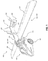
- FIG. 4 shows an exemplary embodiment of the central wing panel 300.
- the central wing panel 300 has a front frame section 310 including a front transverse member and a wing support member, and a rear frame section 320 including a rear transverse member and wing locking member, that are connected by one or more cross members 330.
- the front frame section 310 and the rear frame section 320, as shown in FIGS. 4-6 have a plurality of vertical, horizontal, and diagonal members interconnected.
- the front frame section 310 is rotatably coupled to front parts of the first wing 301 and the second wing 302 (not shown in FIG. 4 ) by means of wing pivot connectors.
- the front frame section 310 has a pair of hinge mechanisms 311 and 312 vertically oriented and positioned at opposite ends.
- a first vertical axis 321 and a second vertical axis 322 are formed by the hinge mechanisms 311 and 312.
- the first wing 301 and the second wing 302 are configured to rotate about the first vertical axis 321 and the second vertical axis 322.
- the front frame section 310 includes stoppers 323 and 324 that extend toward the front portion of the first wing 301 and the second wing 302, as shown in FIG. 4 .
- Stoppers 323 and 324 are configured to restrict rotation of the first wing 301 and the second wing 302 beyond parallel in the forward direction (i.e. an extended position). Rotation of the first wing 301 and the second wing 302 about the first vertical axis 321 and the second vertical axis 322 is a part of the transition between air operation mode (see FIG. 1 ) and ground operation mode (see FIG. 2 ) for the vehicle 100.
- the first wing 301 and the second wing 302 are configured to be rotated about first vertical axis 321 and second vertical axis 322 by one or more actuator mechanisms.
- the central wing panel 300 includes a first actuator 341 connected to the front frame section 310 and linked to the first wing 301, as shown in FIG. 4 .
- the first actuator 341 is configured to extend or contract causing rotation of first wing 301 about first vertical axis 321.
- the central wing panel 300 includes a second actuator (not shown) connected to the front frame section 310 and linked to the second wing 302 (not shown) configured to cause rotation of the second wing 302 about the second vertical axis 322.
- the front frame section 310 is rotatably coupled to the structural frame of the vehicle 100.
- a lower member defining a front transverse member 313 of the front frame section 310 can be coupled to the structural frame of the vehicle 100 such that a first horizontal axis 314 substantially parallel to the member 313 is formed.
- the central wing panel 300 is configured to rotate about the first horizontal axis 314 as shown in FIG. 4 .
- the central wing panel 300 rotates about the first horizontal axis 314 by one or more actuator mechanisms.
- the central wing panel 300 can include a third actuator 343 coupled to the central wing panel 300 at one end and coupled to the structural frame (not shown) of the vehicle 100. As shown in FIG. 4 , the third actuator 343 is coupled to a lower portion of the rear frame section 320. It is contemplated that in other embodiments additional actuators can be used to drive rotation of the central wing panel 300 about the first horizontal axis 314.
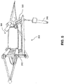
- FIG. 5 shows third actuator 343 at least partially extended so that first wing 301 is substantially horizontal.
- the third actuator 343 is retracted causing the central wing panel 300 to rotate about the first horizontal axis 314 an angle ⁇ .
- Angle ⁇ can be, for example, about 0 to 15 degrees.
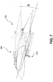
- FIG. 7 shows rotation of the central wing panel 300 about the first horizontal axis 314 by the third actuator 343 (not shown), which enables adjustment of the incidence of the wings relative to horizontal by an angle ⁇ .
- Angle a can be, for example, about 0 to 15 degrees and can correspond with angle ⁇ .
- Angle ⁇ represents the angle of attack for the wings of the vehicle 100 in flight.
- an operator of the vehicle 100 is able to adjust the incidence of the wing while operating in the air.
- adjusting the angle of attack is advantageous because the angle of attack affects the amount of lift produced by the wings.
- For take-off and landing it is advantageous to increase the angle of incidence of the wing to increase the angle of attack and increase lift at low speeds.
- the angle of incidence can be decreased to reduce drag and increase air speed when flying at normal attitudes.
- the central wing panel 300 also is configured such that the first wing 301 and the second wing 302 rotate about the first vertical axis 321 and the second vertical axis 322 while the central wing panel 300 is rotated or has been rotated about the first horizontal axis 314. These two separate axis of rotation can enable the outer ends of the first wing 301 and the second wing 302 to be elevated above the tail 140 during the transition between air operation mode and ground operation mode. For example, as shown in FIG. 3 , if wings 130 are retracted back and remained substantially parallel to the ground, they will strike the tail 140 unless they are sufficiently short. However, the central wing panel 300 enables the wings 130 to be elevated above tail 140 when retracting or opening to avoid interference.
- the rear frame section 320 is coupled to the first wing 301 and the second wing 302 (not shown).
- the rear frame section 320 is rotatably releasably coupled to the first wing 301 and the second wing 302 by way of a hinge joint 325.
- the hinge joints 325 comprise a ball attached to a member of the rear frame section 320, and a "U" shaped pocket configured to receive the ball, the ball and socket defining lock segments.
- the hinge joints 325 are configured to restrict the movement of the first wing 301 and the second wing 302, as shown in FIG. 4 .
- first wing 301 may be prevented from rotating about the first vertical axis 321 when the rear frame section 320 is coupled to the first wing 301 by way of the hinge joint 325. It is contemplated that other rotatably releasable joints may be utilized.
- the rear frame section 320 is configured to rotate about a second horizontal axis 315 located at a lower portion of the rear frame section 320.
- the second horizontal axis 315 extends substantially parallel along the length of the rear frame section 320.
- the rear frame section 320 may be configured to rotate an angle ⁇ about the second horizontal axis 315.
- Angle ⁇ can be, for example, between about 0 and 80 degrees.
- Rotating the rear frame section 320 about the second horizontal axis 315 drops the rear frame section 320 below a lower surface of the first wing 301 and the second wing 302 (not shown) so that when the first wing 301 and the second wing 302 rotate toward one another about the first vertical axis 321 and the second vertical axis 322, the first wing 301 and the second wing 302 retract (e.g., when transitioning to ground mode) over rear frame section 320.
- one or more actuator mechanisms are configured to rotate the rear frame section 320 about the second horizontal axis 315.
- a fourth actuator 344 as shown in FIG. 4 is configured to extend and retract to cause rotation of the rear frame section 320.
- the fourth actuator 344 is connected at one end to an upper member of the rear frame section 320 while the other end is connected to the structural frame (not shown).
- a third horizontal axis 316 extends along the length of the first wing 301 and the second wing 302.
- the first wing 301 is configured such that one or more ailerons 131 and flaps are configured to rotate about the third horizontal axis 316 such that the ailerons and flaps fold over onto the top front portion of the first wing 301 thereby reducing the depth of the first wing 301.
- the second wing 302 is equivalently constructed. Reducing the depth of the first wing 301 and the second wing 302 allows a reduced width of the wings 130 when retracted for ground operation mode.
- Ailerons 131 and the flaps are configured to be rotated about the third horizontal axis 316 by one or more actuator mechanisms.
- a fifth actuator 345 is configured to rotate ailerons 131 and the flaps about the third horizontal axis 316 of the first wing 301.
- a sixth actuator is configured to rotate ailerons 131 and the flaps about the third horizontal axis 316 of the second wing 302.
- the actuators described herein may be electric, hydraulic, pneumatic, or other source know in the art. It is also contemplated that others mechanism may be utilized to cause rotation about the vertical and horizontal axis described herein. For example, gears, levers, cables, etc.
- the vehicle 100 is configured to operate each actuator individually and independently or two or more actuators could be synchronized in their operation.
- the first actuator 341, the second actuator, and the third actuator 343 are configured to operate simultaneously for a period.
- the vehicle 100 when transforming from air operation mode to ground operation mode the vehicle 100 is configured to actuate the fourth actuator 344, the fifth actuator 345, and the sixth actuator prior to actuating the first actuator 341, the second actuator 342, and the third actuator 343.
- the vehicle 100 when transforming from ground operation mode to air operation mode the vehicle 100 is configured to actuate the first actuator 341, the second actuator, and the third actuator 343 prior to the fourth actuator 344, the fifth actuator 345, and the sixth actuator.
Description
- This invention relates generally to a central wing panel for a flying vehicle. One particular use of such central wing panel is for mounting the wings on a hybrid air and ground transportation vehicle.
- Vehicles for ground transportation (e.g., automobiles) and for air transportation (e.g., airplanes) have existed for many years. In more recent years increasing effort has been directed to developing another category of transportation vehicles, that is a hybrid vehicle that is fully compatible with air and normal ground use all in one.
- One such hybrid vehicle is the "Terrafugia Transition" described in
WO 2007/114877 ("WO '877"). WO '877 publication discloses a vehicle that is both an automobile as well as a two-passenger aircraft, equipped with a four-wheel chassis and foldable wings. The power of the engine on the ground is transferred to the front axle, the wheels being steered by a conventional steering wheel, while in the air the engine spins the propeller positioned at the rear of the vehicle fuselage. The vehicle is equipped with compact wing roots, which are rigidly connected to the fuselage at both sides of the vehicle, and to which the wings are connected through a first hinge mechanism. The first hinge mechanism allows the collapsing of the wings vertically. The axis of rotation for the first hinge mechanism is parallel to a longitudinal axis of the vehicle (i.e., axis of roll). The wings include a second hinge mechanism midway out on the wing enabling collapsing of the outer half of the wing downwards. The axis of rotation for the second hinge mechanism is also parallel to the longitudinal axis of the vehicle. - "AeroMobil" is another hybrid vehicle, described in
WO 2013/032409 ("WO '409"). WO '409 also discloses a hybrid vehicle in which the vehicle has a simple cross bar construction for its central wing panel with a single degree of freedom by way of two perpendicular axes of rotation at both ends of the panel. The central wing panel enables retraction of the wings about the axes of rotation. - Both the "Terrafugia Transition" and "Aeromobil" have mechanisms that enable collapsing of the wings, but neither of the mechanism are capable of controlling other wing functions, for example, adjusting angle of attack, adjust ailerons, etc. Therefore, separate independent systems or mechanisms are required which often can increase complexity, cost, and weight of the vehicle.
- The solution to these problems provides a central wing panel (i.e. a wing mounting structure) configured for mounting of the wings, transformation (i.e. movement between operating positions), and change of angle of attack.
- In a first aspect, a central wing panel for a flying vehicle comprising a body and wings positioned on each side of the body, the central wing panel, comprises: a support structure for connection to the body so as to be substantially aligned with a longitudinal axis thereof; a front transverse member mounted at a front part of the support structure, and a rear transverse member mounted at a rear part of the support structure, wherein the front and rear transverse members each have a substantially horizontal rotation axis perpendicular to the longitudinal axis of the body; a wing support member connected to the front transverse member and rotatable about the axis of rotation of the front transverse member, the wing support member being provided with a wing pivot connectors by which a front part of each wing is connected to the wing support member, each wing being pivotable around a substantially vertical axis of a respective connector between a first wing position in which the wing extends substantially horizontally from the body, and a second wing position in which the wing lies substantially horizontally parallel to the longitudinal axis of the body; a wing locking member connected to the rear transverse member, the wing locking member being movable by rotation about the rear transverse member between a locked position, in which lock segments on the wing locking member engage with corresponding lock segments at a rear part of each wing so as to prevent movement of the wing from the first wing position to the second wing position, and a release position in which the lock segments are disengaged from the corresponding lock segments so as to allow movement of the wing between the first wing position and the second wing position; and an actuator for pivoting the support structure about the rotation axis of the front transverse member so as to adjust the angle of incidence of the wings when in the first wing position.
- In a second aspect, a flying vehicle comprises a body and wings positioned on each side of the body, the wings being mounted on the body by means of a central wing panel of the first aspect; and a hybrid transportation vehicle for ground and air transportation comprises: a body, a cabin, a tail, a set of wheels including steerable wheels and driven wheels, an engine, a propeller, and wings positioned on each side of the body, the wings being mounted on the body by means of a central wing panel of the first aspect.
- In a third aspect, a method of operating the vehicle of the second aspect, wherein the wings are initially in the first wing position, comprises: rotating the wing locking member from the locked position to the release position; rotating each wing about its respective wing pivot connector between the first wing position and the second wing position; operating the actuator so as to tilt the structure while the wings are moving between the first and second wing positions.
- In a fourth aspect, a method of operating the vehicle of the second aspect, wherein the wings are initially in the second wing position, comprises: rotating each wing about its respective wing pivot connector between the second wing position and the first wing position; operating the actuator so as to tilt the structure while the wings are moving between the second and first wing positions; and rotating the wing locking member from the release position to the locked position.
- The accompanying drawings illustrate embodiments of the central wing panel and methods of operation, where:
-
FIG. 1 is side perspective view of one embodiment of a hybrid vehicle configured for air operation. -
FIG. 2 is a side perspective view of a hybrid vehicle configured for ground operation. -
FIG. 3 is a side view of a hybrid vehicle configured for air operation showing a portion of one embodiment of a central wing panel. -
FIG. 4 is a portion of one embodiment of a central wing panel. -
FIG. 5 is a portion of one embodiment of a central wing panel. -
FIG. 6 is a portion of one embodiment of a central wing panel. -
FIG. 7 is a portion of one embodiment of a central wing panel. -
FIG. 8 is a portion of one embodiment of a central wing panel. - Reference will now be made in detail to the non-limiting exemplary embodiments illustrated in the accompanying drawings. Wherever possible, the same reference numbers will be used throughout the drawings to refer to the same or like parts.
-
FIGS. 1 and2 show ahybrid vehicle 100, according to one exemplary embodiment configured for air operation and ground operation respectively. Thevehicle 100 is configured for air operation at least during flight, taxiing, takeoff, and landing. The configuration of thevehicle 100 may be transformed from air operation to ground operation or vice versa while on the ground. Thevehicle 100 is configured for ground operation while traveling on the ground, for example, driving along roadways. - The
vehicle 100 comprises abody 110, acabin 120, a set of retractable wings 130 (afirst wing 301 and a second wing 302), atail 140, apropeller 150, and wheels, which can include a set offront wheels 161 andrear wheels 162. Thevehicle 100 also has a chassis andengine 170 contained within thebody 110 configured to drive the propeller 150 (during air operation) or thefront wheels 161 or rear wheels 162 (during ground operation). - As shown in
FIGS. 1 and2 , theretractable wings 130 include anaileron 131 on eachwing 130. Eachaileron 131 is attached to a trailing edge of therespective wing 130 by means of a hinge. Theailerons 131 are used to control the rolling of thevehicle 100 about its longitudinal axis when flying, in the usual manner. Thetail 140 includes anelevator 141 on each side of thetail 140. Theelevators 141 are attached to a trailing edge of eachtail section 110 by means of a hinge. Theelevators 141 are used to controlvehicle 100 pitch when flying, in the usual manner. - The
vehicle 100 further includes acentral wing panel 300 as shown inFIGS. 3-8 . InFIGS. 3-8 only thefirst wing 301 or thesecond wing 302 has been shown in each figure to enable better illustration of other components. It is understood that although both wings are not shown in each figure it is intended that all aspects as described herein regarding whichever wing is shown also applies to the other wing not shown. - The
central wing panel 300 is positioned within thebody 110 of thevehicle 100 so as to be substantially aligned with its longitudinal axis, for example, as shown inFIG. 3 . Thecentral wing panel 300 is coupled to thewings 130 and a structural frame (not shown) of thevehicle 100 that may be contained within thebody 110. Thecentral wing panel 300 can be configured to allow adjustment of thewings 130 about multiple axes. -
FIG. 4 shows an exemplary embodiment of thecentral wing panel 300. Thecentral wing panel 300 has afront frame section 310 including a front transverse member and a wing support member, and arear frame section 320 including a rear transverse member and wing locking member, that are connected by one ormore cross members 330. Thefront frame section 310 and therear frame section 320, as shown inFIGS. 4-6 have a plurality of vertical, horizontal, and diagonal members interconnected. - As shown in
FIG. 4 , thefront frame section 310 is rotatably coupled to front parts of thefirst wing 301 and the second wing 302 (not shown inFIG. 4 ) by means of wing pivot connectors. Thefront frame section 310 has a pair ofhinge mechanisms vertical axis 321 and a secondvertical axis 322 are formed by thehinge mechanisms first wing 301 and thesecond wing 302 are configured to rotate about the firstvertical axis 321 and the secondvertical axis 322. Thefront frame section 310 includesstoppers first wing 301 and thesecond wing 302, as shown inFIG. 4 .Stoppers first wing 301 and thesecond wing 302 beyond parallel in the forward direction (i.e. an extended position). Rotation of thefirst wing 301 and thesecond wing 302 about the firstvertical axis 321 and the secondvertical axis 322 is a part of the transition between air operation mode (seeFIG. 1 ) and ground operation mode (seeFIG. 2 ) for thevehicle 100. - The
first wing 301 and thesecond wing 302 are configured to be rotated about firstvertical axis 321 and secondvertical axis 322 by one or more actuator mechanisms. For example, thecentral wing panel 300 includes afirst actuator 341 connected to thefront frame section 310 and linked to thefirst wing 301, as shown inFIG. 4 . Thefirst actuator 341 is configured to extend or contract causing rotation offirst wing 301 about firstvertical axis 321. Thecentral wing panel 300 includes a second actuator (not shown) connected to thefront frame section 310 and linked to the second wing 302 (not shown) configured to cause rotation of thesecond wing 302 about the secondvertical axis 322. - The
front frame section 310 is rotatably coupled to the structural frame of thevehicle 100. For example, a lower member defining a fronttransverse member 313 of thefront frame section 310 can be coupled to the structural frame of thevehicle 100 such that a firsthorizontal axis 314 substantially parallel to themember 313 is formed. Thecentral wing panel 300 is configured to rotate about the firsthorizontal axis 314 as shown inFIG. 4 . - The
central wing panel 300 rotates about the firsthorizontal axis 314 by one or more actuator mechanisms. For example, thecentral wing panel 300 can include athird actuator 343 coupled to thecentral wing panel 300 at one end and coupled to the structural frame (not shown) of thevehicle 100. As shown inFIG. 4 , thethird actuator 343 is coupled to a lower portion of therear frame section 320. It is contemplated that in other embodiments additional actuators can be used to drive rotation of thecentral wing panel 300 about the firsthorizontal axis 314. -
FIG. 5 showsthird actuator 343 at least partially extended so thatfirst wing 301 is substantially horizontal. InFIG. 6 , thethird actuator 343 is retracted causing thecentral wing panel 300 to rotate about the firsthorizontal axis 314 an angle β. Angle β can be, for example, about 0 to 15 degrees.FIG. 7 shows rotation of thecentral wing panel 300 about the firsthorizontal axis 314 by the third actuator 343 (not shown), which enables adjustment of the incidence of the wings relative to horizontal by an angle α. Angle a can be, for example, about 0 to 15 degrees and can correspond with angle β. Angle α represents the angle of attack for the wings of thevehicle 100 in flight. Therefore, by way of thethird actuator 343, an operator of thevehicle 100 is able to adjust the incidence of the wing while operating in the air. As is known in the art, adjusting the angle of attack is advantageous because the angle of attack affects the amount of lift produced by the wings. For take-off and landing it is advantageous to increase the angle of incidence of the wing to increase the angle of attack and increase lift at low speeds. By increasing lift, the distance needed for take-off is reduced allowing for use of shorter runways and similarly the distance needed for landing can also be reduced. While in the air (e.g., not landing or taking off), the angle of incidence can be decreased to reduce drag and increase air speed when flying at normal attitudes. - The
central wing panel 300 also is configured such that thefirst wing 301 and thesecond wing 302 rotate about the firstvertical axis 321 and the secondvertical axis 322 while thecentral wing panel 300 is rotated or has been rotated about the firsthorizontal axis 314. These two separate axis of rotation can enable the outer ends of thefirst wing 301 and thesecond wing 302 to be elevated above thetail 140 during the transition between air operation mode and ground operation mode. For example, as shown inFIG. 3 , ifwings 130 are retracted back and remained substantially parallel to the ground, they will strike thetail 140 unless they are sufficiently short. However, thecentral wing panel 300 enables thewings 130 to be elevated abovetail 140 when retracting or opening to avoid interference. - As shown in
FIG. 4 , therear frame section 320 is coupled to thefirst wing 301 and the second wing 302 (not shown). Therear frame section 320 is rotatably releasably coupled to thefirst wing 301 and thesecond wing 302 by way of ahinge joint 325. The hinge joints 325 comprise a ball attached to a member of therear frame section 320, and a "U" shaped pocket configured to receive the ball, the ball and socket defining lock segments. The hinge joints 325 are configured to restrict the movement of thefirst wing 301 and thesecond wing 302, as shown inFIG. 4 . For example, thefirst wing 301 may be prevented from rotating about the firstvertical axis 321 when therear frame section 320 is coupled to thefirst wing 301 by way of thehinge joint 325. It is contemplated that other rotatably releasable joints may be utilized. - As shown in
FIGS. 4 and8 , therear frame section 320 is configured to rotate about a secondhorizontal axis 315 located at a lower portion of therear frame section 320. The secondhorizontal axis 315 extends substantially parallel along the length of therear frame section 320. Therear frame section 320 may be configured to rotate an angle γ about the secondhorizontal axis 315. Angle γ can be, for example, between about 0 and 80 degrees. Rotating therear frame section 320 about the secondhorizontal axis 315 drops therear frame section 320 below a lower surface of thefirst wing 301 and the second wing 302 (not shown) so that when thefirst wing 301 and thesecond wing 302 rotate toward one another about the firstvertical axis 321 and the secondvertical axis 322, thefirst wing 301 and thesecond wing 302 retract (e.g., when transitioning to ground mode) overrear frame section 320. According to an exemplary embodiment, one or more actuator mechanisms are configured to rotate therear frame section 320 about the secondhorizontal axis 315. For example, afourth actuator 344 as shown inFIG. 4 is configured to extend and retract to cause rotation of therear frame section 320. Thefourth actuator 344 is connected at one end to an upper member of therear frame section 320 while the other end is connected to the structural frame (not shown). - As shown in
FIG. 4 , a thirdhorizontal axis 316 extends along the length of thefirst wing 301 and thesecond wing 302. Thefirst wing 301 is configured such that one ormore ailerons 131 and flaps are configured to rotate about the thirdhorizontal axis 316 such that the ailerons and flaps fold over onto the top front portion of thefirst wing 301 thereby reducing the depth of thefirst wing 301. Thesecond wing 302 is equivalently constructed. Reducing the depth of thefirst wing 301 and thesecond wing 302 allows a reduced width of thewings 130 when retracted for ground operation mode.Ailerons 131 and the flaps are configured to be rotated about the thirdhorizontal axis 316 by one or more actuator mechanisms. For example, afifth actuator 345 is configured to rotateailerons 131 and the flaps about the thirdhorizontal axis 316 of thefirst wing 301. A sixth actuator is configured to rotateailerons 131 and the flaps about the thirdhorizontal axis 316 of thesecond wing 302. - The actuators described herein may be electric, hydraulic, pneumatic, or other source know in the art. It is also contemplated that others mechanism may be utilized to cause rotation about the vertical and horizontal axis described herein. For example, gears, levers, cables, etc. The
vehicle 100 is configured to operate each actuator individually and independently or two or more actuators could be synchronized in their operation. For example, according to one exemplary embodiment, thefirst actuator 341, the second actuator, and thethird actuator 343 are configured to operate simultaneously for a period. In yet another embodiment, when transforming from air operation mode to ground operation mode thevehicle 100 is configured to actuate thefourth actuator 344, thefifth actuator 345, and the sixth actuator prior to actuating thefirst actuator 341, the second actuator 342, and thethird actuator 343. Conversely, when transforming from ground operation mode to air operation mode thevehicle 100 is configured to actuate thefirst actuator 341, the second actuator, and thethird actuator 343 prior to thefourth actuator 344, thefifth actuator 345, and the sixth actuator. - Various modifications and variations can be made to the central wing panel and methods described herein. At the same time at proper positions of the wording, it is possible to substitute the term rotation by the term "turn" or "half-turn".
Claims (16)
- A central wing panel (300) for a flying vehicle (100) comprising a body (110) and wings (130, 301, 302) positioned on each side of the body (110), characterised in that it comprises:- a support structure for connection to the body (110) so as to be substantially aligned with a longitudinal axis thereof;- a front transverse member (313) mounted at a front part of the support structure, and a rear transverse member (320) mounted at a rear part of the support structure, wherein the front and rear transverse members (313, 320) each have a substantially horizontal rotation axis (314, 315) perpendicular to the longitudinal axis of the body (110);- a wing support member (310) connected to the front transverse member (313) and rotatable about the axis of rotation (314) of the front transverse member (313), the wing support member (310) being provided with wing pivot connectors (311, 312) by which a front part of each wing (130, 301, 302) is connected to the wing support member (310), each wing (130, 301, 302) being pivotable around a substantially vertical axis (321, 322) of a respective connector (311, 312) between a first wing position in which the wing (130, 301, 302) extends substantially horizontally from the body (110), and a second wing position in which the wing (130, 301, 302) lies substantially horizontally parallel to the longitudinal axis of the body (110);- a wing locking member (320) connected to the rear transverse member (320), the wing locking member (320) being movable by rotation about the axis of rotation (315) of the rear transverse member (320) between a locked position, in which lock segments on the wing locking member (320) engage with corresponding lock segments at a rear part of each wing (130, 301, 302) so as to prevent movement of the wing (130, 301, 302) from the first wing position to the second wing position, and a release position in which the lock segments are disengaged from the corresponding lock segments so as to allow movement of the wing (130, 301, 302) between the first wing position and the second wing position; and- an actuator (343) for pivoting the support structure about the rotation axis (314) of the front transverse member (313) so as to adjust the angle of incidence of the wings (130, 301, 302) when in the first wing position.
- The central wing panel of claim 1, characterized in that the support structure comprises:- a front frame section defining the front transverse member and wing support member, and a rear frame section, defining the rear transverse member and wing locking member, connected by one or more cross members;- the wing pivot connectors are positioned near opposite ends of the front frame section and the rear frame section is configured to rotate about the rear transverse member rotation axis between the locked position and the release position.
- The central wing panel of claim 1 or 2 characterized in that it further comprises at least a first further actuator for moving the wings between the first and second wing positions.
- The central wing panel of claim 1, 2, or 3 characterized in that the actuator is configured to rotate the support structure through an angle of up to 15 degrees.
- The central wing panel of claim 2 characterized in that it further includes at least a second further actuator coupled to the rear frame section and configured to rotate the rear frame section about the rear transverse member rotation axis .
- The central wing panel of claim 5, characterized in that the second further actuator is configured to rotate the rear frame section through an angle of up to 80 degrees.
- A flying vehicle comprising a body and wings positioned on each side of the body characterized in that the wings are mounted on the body by means of a central wing panel of any preceding claim.
- A hybrid transportation vehicle for ground and air transportation, comprising a body, a cabin, a tail, a set of wheels including steerable wheels and driven wheels, an engine, a propeller, and wings positioned on each side of the body, characterized in that the wings being mounted on the body by means of a central wing panel of any of claims 1-6.
- The vehicle of claim 7 and 8 characterized in that each wing includes a set of ailerons and a set of flaps connected to its trailing edge, and the ailerons and the flaps are configured to rotate about an axis extending along the trailing edge between a deployed position in which the ailerons and flaps extend from the trailing edge, and a folded position in which the ailerons and flaps overly an upper surface of the wing.
- The vehicle of claim 9 characterized in that it further comprises at least one actuator for rotating the ailerons and flaps between the deployed position and the folded position.
- A method of operating the vehicle of any of claims 7 - 10 wherein the wings are initially in the first wing position, characterized in that it comprises:- rotating the wing locking member from the locked position to the release position;- rotating each wing about its respective wing pivot connector between the first wing position and the second wing position;- operating the actuator so as to tilt the structure while the wings are moving between the first and second wing positions.
- The method of claim 11, wherein each wing includes a set of ailerons and a set of flaps connected to its trailing edge, characterized in that it comprises rotating the ailerons and the flaps about an axis extending along the trailing edge between a deployed position in which the ailerons and flaps extend from the trailing edge when the wing is initially in the first wing position, and a folded position in which the ailerons and flaps overly an upper surface of the wing when the wing begins to move to the second wing position.
- A method of operating the vehicle of any of claims 7 - 10 wherein the wings are initially in the second wing position characterized in that it comprises:- rotating each wing about its respective wing pivot connector between the second wing position and the first wing position;- operating the actuator so as to tilt the structure while the wings are moving between the second and first wing positions; and- rotating the wing locking member from the release position to the locked position.
- The method of claim 13, wherein each wing includes a set of ailerons and a set of flaps connected to its trailing edge, characterized in that it comprises rotating the ailerons and the flaps about an axis extending along the trailing edge between a folded position in which the ailerons and flaps overly an upper surface of the wing when the wing is in the second wing position, and a. deployed position in which the ailerons and flaps extend from the training edge when the wing is moved to the first wing position.
- The method of claim 13 or 14 characterized in that it comprises following movement of the wings to the first wing position, operating the actuator so as to tilt the structure so as to adjust the incidence of the wings to present a predetermined angle of attack in a direction of travel of the vehicle.
- The method of any of claims 11 - 15 characterized in that it comprises operating the actuator so as to tilt the structure while the wings are moving between the first and second wing positions so that the wings clear any vertical tail sections of the vehicle when moving between the first and second wing positions.
Applications Claiming Priority (3)
| Application Number | Priority Date | Filing Date | Title |
|---|---|---|---|
| SK50123-2014U SK7493Y1 (en) | 2014-10-08 | 2014-10-08 | Center of the flying vehicle and its control |
| SK50058-2014A SK288638B6 (en) | 2014-10-08 | 2014-10-08 | Center of the flying vehicle and its control |
| PCT/SK2015/000004 WO2016057004A1 (en) | 2014-10-08 | 2015-10-08 | Central wing panel for a flying vehicle and method of its control |
Publications (2)
| Publication Number | Publication Date |
|---|---|
| EP3204246A1 EP3204246A1 (en) | 2017-08-16 |
| EP3204246B1 true EP3204246B1 (en) | 2019-06-05 |
Family
ID=60084164
Family Applications (1)
| Application Number | Title | Priority Date | Filing Date |
|---|---|---|---|
| EP15801514.9A Not-in-force EP3204246B1 (en) | 2014-10-08 | 2015-10-08 | Wing central panel of hybrid transportation vehicle for the ground and the air |
Country Status (8)
| Country | Link |
|---|---|
| US (1) | US10611459B2 (en) |
| EP (1) | EP3204246B1 (en) |
| JP (1) | JP2017534515A (en) |
| KR (1) | KR20170066563A (en) |
| CN (1) | CN107107690B (en) |
| BR (1) | BR112017006721A2 (en) |
| RU (1) | RU2687543C2 (en) |
| WO (1) | WO2016057004A1 (en) |
Families Citing this family (9)
| Publication number | Priority date | Publication date | Assignee | Title |
|---|---|---|---|---|
| DE102016006696A1 (en) | 2016-05-27 | 2017-11-30 | Christoph Jaeger | Flight Car System |
| US20180079488A1 (en) * | 2016-09-21 | 2018-03-22 | Bell Helicopter Textron Inc. | Foldable aircraft with anhedral stabilizing wings |
| EP3335916A1 (en) | 2016-12-13 | 2018-06-20 | AeroMobil R&D, s. r. o. | Acceleration control for a convertible air - road vehicle |
| EP3335914B1 (en) | 2016-12-13 | 2019-11-13 | AeroMobil R&D, s. r. o. | Vehicle including control pedal arrangement |
| EP3335915B1 (en) | 2016-12-13 | 2019-12-04 | AeroMobil R&D, s. r. o. | Stability control for operation of a convertible air - road vehicle |
| EP3366570A1 (en) | 2017-02-22 | 2018-08-29 | AeroMobil R&D, s. r. o. | Wing folding |
| EP3412560B1 (en) | 2017-06-05 | 2020-02-12 | AeroMobil R&D, s. r. o. | Wing folding |
| EP3418184A1 (en) | 2017-06-20 | 2018-12-26 | AeroMobil R&D, s. r. o. | Wing flap system for flying car |
| JP7265260B2 (en) * | 2019-09-17 | 2023-04-26 | 国立研究開発法人宇宙航空研究開発機構 | aircraft |
Citations (6)
| Publication number | Priority date | Publication date | Assignee | Title |
|---|---|---|---|---|
| GB556478A (en) * | 1942-04-04 | 1943-10-06 | Osmond Ernst Fletcher | Improvements in or relating to aircraft wings |
| FR2577198A1 (en) * | 1985-02-13 | 1986-08-14 | Bazin Claudine | CONVERTIBLE AIRPLANE |
| US4881700A (en) * | 1988-01-05 | 1989-11-21 | Branko Sarh | Convertible fixed wing aircraft |
| US20090302151A1 (en) * | 2007-09-10 | 2009-12-10 | Alan Glen Holmes | Aircraft with fixed, swinging and folding wings |
| WO2010012285A2 (en) * | 2008-07-28 | 2010-02-04 | Fleck Fitness Concepts Gmbh | Combined air, water and road vehicle |
| WO2013032409A1 (en) * | 2011-08-30 | 2013-03-07 | Aeromobil, S.R.O. | Transformation method of hybrid transportation vehicle for ground and air, and hybrid transportation vehicle itself |
Family Cites Families (12)
| Publication number | Priority date | Publication date | Assignee | Title |
|---|---|---|---|---|
| US2692095A (en) * | 1952-08-01 | 1954-10-19 | Fred A Carpenter | Convertible airplane and highway vehicle |
| US2940688A (en) * | 1956-08-27 | 1960-06-14 | Edward F Bland | Roadable aircraft and sailboat |
| RU2058911C1 (en) * | 1988-06-15 | 1996-04-27 | Казанский государственный технический университет им.А.Н.Туполева | Swivel unit for folding wing at basing |
| JPH0338499A (en) * | 1989-07-03 | 1991-02-19 | Mitsubishi Heavy Ind Ltd | Aircraft having changeable main wing |
| JPH04297798A (en) * | 1991-03-04 | 1992-10-21 | Mitsubishi Electric Corp | Guided missile |
| DE4119613C2 (en) * | 1991-06-14 | 1997-03-27 | Diehl Gmbh & Co | Missiles with fold-out guidance devices |
| US8157206B2 (en) * | 2008-06-11 | 2012-04-17 | Icon Aircraft, Inc. | Two-motion wing-fold mechanism with independent load path |
| US8464979B2 (en) * | 2009-06-02 | 2013-06-18 | Sunstar IM | Foldable swan-wings aircraft |
| RU2403177C1 (en) | 2009-07-31 | 2010-11-10 | Общество С Ограниченной Ответственностью "Научно-Производственная Фирма "Сигма-Тс" | Aircraft with folding wing and device for aircraft wing folding |
| US8162253B2 (en) * | 2009-08-19 | 2012-04-24 | Seiford Sr Donald S | Convertible vehicle for road, air, and water usage |
| BR112013002735B1 (en) * | 2010-08-03 | 2021-02-02 | Samson Aip, Inc | flight vehicle with retractable wings, wing and frame assembly for a flight vehicle that defines retractable wings and flight vehicle with a swinging wing |
| CN102616096A (en) | 2012-04-24 | 2012-08-01 | 赵辉 | Solar flying automobile with folding wings |
-
2015
- 2015-10-08 RU RU2017115995A patent/RU2687543C2/en not_active IP Right Cessation
- 2015-10-08 US US15/517,545 patent/US10611459B2/en active Active
- 2015-10-08 CN CN201580054659.8A patent/CN107107690B/en not_active Expired - Fee Related
- 2015-10-08 JP JP2017518523A patent/JP2017534515A/en not_active Ceased
- 2015-10-08 KR KR1020177012129A patent/KR20170066563A/en unknown
- 2015-10-08 BR BR112017006721A patent/BR112017006721A2/en not_active Application Discontinuation
- 2015-10-08 WO PCT/SK2015/000004 patent/WO2016057004A1/en active Application Filing
- 2015-10-08 EP EP15801514.9A patent/EP3204246B1/en not_active Not-in-force
Patent Citations (6)
| Publication number | Priority date | Publication date | Assignee | Title |
|---|---|---|---|---|
| GB556478A (en) * | 1942-04-04 | 1943-10-06 | Osmond Ernst Fletcher | Improvements in or relating to aircraft wings |
| FR2577198A1 (en) * | 1985-02-13 | 1986-08-14 | Bazin Claudine | CONVERTIBLE AIRPLANE |
| US4881700A (en) * | 1988-01-05 | 1989-11-21 | Branko Sarh | Convertible fixed wing aircraft |
| US20090302151A1 (en) * | 2007-09-10 | 2009-12-10 | Alan Glen Holmes | Aircraft with fixed, swinging and folding wings |
| WO2010012285A2 (en) * | 2008-07-28 | 2010-02-04 | Fleck Fitness Concepts Gmbh | Combined air, water and road vehicle |
| WO2013032409A1 (en) * | 2011-08-30 | 2013-03-07 | Aeromobil, S.R.O. | Transformation method of hybrid transportation vehicle for ground and air, and hybrid transportation vehicle itself |
Also Published As
| Publication number | Publication date |
|---|---|
| CN107107690B (en) | 2019-10-08 |
| US10611459B2 (en) | 2020-04-07 |
| EP3204246A1 (en) | 2017-08-16 |
| BR112017006721A2 (en) | 2017-12-19 |
| WO2016057004A8 (en) | 2017-04-20 |
| RU2687543C2 (en) | 2019-05-14 |
| CN107107690A (en) | 2017-08-29 |
| KR20170066563A (en) | 2017-06-14 |
| WO2016057004A1 (en) | 2016-04-14 |
| RU2017115995A3 (en) | 2019-03-04 |
| JP2017534515A (en) | 2017-11-24 |
| RU2017115995A (en) | 2018-11-13 |
| US20170305527A1 (en) | 2017-10-26 |
Similar Documents
| Publication | Publication Date | Title |
|---|---|---|
| EP3204246B1 (en) | Wing central panel of hybrid transportation vehicle for the ground and the air | |
| RU2686803C2 (en) | Dirension control system and method for hybrid vehicle of air and ground transport | |
| US8371520B2 (en) | Rapidly convertible hybrid aircraft and manufacturing method | |
| DE3430377C2 (en) | ||
| JP2020534212A (en) | Wing tilt actuation system for electric vertical takeoff and landing (VTOL) aircraft | |
| EP3335914B1 (en) | Vehicle including control pedal arrangement | |
| CA2948145C (en) | A dual-purpose vehicle for air and ground transportation, and related methods | |
| US20030094536A1 (en) | Flyable automobile | |
| JP2001213397A (en) | Improvement of aircraft | |
| DE102016206551A1 (en) | aircraft | |
| WO2018200879A1 (en) | Electrically powered vtol tail-sitter aircraft for providing transportation | |
| EP3763620B1 (en) | Flap actuation system for aircraft | |
| EP3412560B1 (en) | Wing folding | |
| US20070084968A1 (en) | In-flight refueling system, boom, and method for extending range of motion of an in-flight refueling boom | |
| CN209956209U (en) | Unmanned aerial vehicle for vertical take-off and landing of morphing wing | |
| SK500582014A3 (en) | Center of the flying vehicle and its control | |
| SK7493Y1 (en) | Center of the flying vehicle and its control | |
| EP3363735B1 (en) | Undercarriage-mounted airfoil | |
| SK7646Y1 (en) | System and method of controlling the direction of the hybrid transportation vehicle for air and ground | |
| WO2023208887A1 (en) | Aeronautical vehicle and method of transitioning between flight modes for an aeronautical vehicle | |
| CN115157946A (en) | Aerocar wing and rotor hybrid retraction system and aerocar | |
| SK500592014A3 (en) | System and method of controlling the direction of the hybrid vehicle for air and land | |
| WO2018234104A1 (en) | Wing flap system for flying car |
Legal Events
| Date | Code | Title | Description |
|---|---|---|---|
| STAA | Information on the status of an ep patent application or granted ep patent |
Free format text: STATUS: THE INTERNATIONAL PUBLICATION HAS BEEN MADE |
|
| PUAI | Public reference made under article 153(3) epc to a published international application that has entered the european phase |
Free format text: ORIGINAL CODE: 0009012 |
|
| STAA | Information on the status of an ep patent application or granted ep patent |
Free format text: STATUS: REQUEST FOR EXAMINATION WAS MADE |
|
| 17P | Request for examination filed |
Effective date: 20170503 |
|
| AK | Designated contracting states |
Kind code of ref document: A1 Designated state(s): AL AT BE BG CH CY CZ DE DK EE ES FI FR GB GR HR HU IE IS IT LI LT LU LV MC MK MT NL NO PL PT RO RS SE SI SK SM TR |
|
| AX | Request for extension of the european patent |
Extension state: BA ME |
|
| DAV | Request for validation of the european patent (deleted) | ||
| DAX | Request for extension of the european patent (deleted) | ||
| REG | Reference to a national code |
Ref country code: HK Ref legal event code: DE Ref document number: 1242267 Country of ref document: HK |
|
| GRAP | Despatch of communication of intention to grant a patent |
Free format text: ORIGINAL CODE: EPIDOSNIGR1 |
|
| STAA | Information on the status of an ep patent application or granted ep patent |
Free format text: STATUS: GRANT OF PATENT IS INTENDED |
|
| INTG | Intention to grant announced |
Effective date: 20181220 |
|
| GRAS | Grant fee paid |
Free format text: ORIGINAL CODE: EPIDOSNIGR3 |
|
| GRAA | (expected) grant |
Free format text: ORIGINAL CODE: 0009210 |
|
| STAA | Information on the status of an ep patent application or granted ep patent |
Free format text: STATUS: THE PATENT HAS BEEN GRANTED |
|
| AK | Designated contracting states |
Kind code of ref document: B1 Designated state(s): AL AT BE BG CH CY CZ DE DK EE ES FI FR GB GR HR HU IE IS IT LI LT LU LV MC MK MT NL NO PL PT RO RS SE SI SK SM TR |
|
| REG | Reference to a national code |
Ref country code: GB Ref legal event code: FG4D |
|
| REG | Reference to a national code |
Ref country code: CH Ref legal event code: EP |
|
| REG | Reference to a national code |
Ref country code: AT Ref legal event code: REF Ref document number: 1139618 Country of ref document: AT Kind code of ref document: T Effective date: 20190615 |
|
| REG | Reference to a national code |
Ref country code: IE Ref legal event code: FG4D |
|
| REG | Reference to a national code |
Ref country code: DE Ref legal event code: R096 Ref document number: 602015031500 Country of ref document: DE |
|
| REG | Reference to a national code |
Ref country code: CH Ref legal event code: NV Representative=s name: WEINMANN ZIMMERLI, CH |
|
| REG | Reference to a national code |
Ref country code: NL Ref legal event code: MP Effective date: 20190605 |
|
| REG | Reference to a national code |
Ref country code: LT Ref legal event code: MG4D |
|
| PG25 | Lapsed in a contracting state [announced via postgrant information from national office to epo] |
Ref country code: ES Free format text: LAPSE BECAUSE OF FAILURE TO SUBMIT A TRANSLATION OF THE DESCRIPTION OR TO PAY THE FEE WITHIN THE PRESCRIBED TIME-LIMIT Effective date: 20190605 Ref country code: AL Free format text: LAPSE BECAUSE OF FAILURE TO SUBMIT A TRANSLATION OF THE DESCRIPTION OR TO PAY THE FEE WITHIN THE PRESCRIBED TIME-LIMIT Effective date: 20190605 Ref country code: SE Free format text: LAPSE BECAUSE OF FAILURE TO SUBMIT A TRANSLATION OF THE DESCRIPTION OR TO PAY THE FEE WITHIN THE PRESCRIBED TIME-LIMIT Effective date: 20190605 Ref country code: HR Free format text: LAPSE BECAUSE OF FAILURE TO SUBMIT A TRANSLATION OF THE DESCRIPTION OR TO PAY THE FEE WITHIN THE PRESCRIBED TIME-LIMIT Effective date: 20190605 Ref country code: LT Free format text: LAPSE BECAUSE OF FAILURE TO SUBMIT A TRANSLATION OF THE DESCRIPTION OR TO PAY THE FEE WITHIN THE PRESCRIBED TIME-LIMIT Effective date: 20190605 Ref country code: FI Free format text: LAPSE BECAUSE OF FAILURE TO SUBMIT A TRANSLATION OF THE DESCRIPTION OR TO PAY THE FEE WITHIN THE PRESCRIBED TIME-LIMIT Effective date: 20190605 Ref country code: NO Free format text: LAPSE BECAUSE OF FAILURE TO SUBMIT A TRANSLATION OF THE DESCRIPTION OR TO PAY THE FEE WITHIN THE PRESCRIBED TIME-LIMIT Effective date: 20190905 |
|
| PGFP | Annual fee paid to national office [announced via postgrant information from national office to epo] |
Ref country code: FR Payment date: 20190913 Year of fee payment: 5 |
|
| PG25 | Lapsed in a contracting state [announced via postgrant information from national office to epo] |
Ref country code: RS Free format text: LAPSE BECAUSE OF FAILURE TO SUBMIT A TRANSLATION OF THE DESCRIPTION OR TO PAY THE FEE WITHIN THE PRESCRIBED TIME-LIMIT Effective date: 20190605 Ref country code: GR Free format text: LAPSE BECAUSE OF FAILURE TO SUBMIT A TRANSLATION OF THE DESCRIPTION OR TO PAY THE FEE WITHIN THE PRESCRIBED TIME-LIMIT Effective date: 20190906 Ref country code: LV Free format text: LAPSE BECAUSE OF FAILURE TO SUBMIT A TRANSLATION OF THE DESCRIPTION OR TO PAY THE FEE WITHIN THE PRESCRIBED TIME-LIMIT Effective date: 20190605 Ref country code: BG Free format text: LAPSE BECAUSE OF FAILURE TO SUBMIT A TRANSLATION OF THE DESCRIPTION OR TO PAY THE FEE WITHIN THE PRESCRIBED TIME-LIMIT Effective date: 20190905 |
|
| REG | Reference to a national code |
Ref country code: AT Ref legal event code: MK05 Ref document number: 1139618 Country of ref document: AT Kind code of ref document: T Effective date: 20190605 |
|
| PG25 | Lapsed in a contracting state [announced via postgrant information from national office to epo] |
Ref country code: NL Free format text: LAPSE BECAUSE OF FAILURE TO SUBMIT A TRANSLATION OF THE DESCRIPTION OR TO PAY THE FEE WITHIN THE PRESCRIBED TIME-LIMIT Effective date: 20190605 Ref country code: PT Free format text: LAPSE BECAUSE OF FAILURE TO SUBMIT A TRANSLATION OF THE DESCRIPTION OR TO PAY THE FEE WITHIN THE PRESCRIBED TIME-LIMIT Effective date: 20191007 Ref country code: SK Free format text: LAPSE BECAUSE OF FAILURE TO SUBMIT A TRANSLATION OF THE DESCRIPTION OR TO PAY THE FEE WITHIN THE PRESCRIBED TIME-LIMIT Effective date: 20190605 Ref country code: RO Free format text: LAPSE BECAUSE OF FAILURE TO SUBMIT A TRANSLATION OF THE DESCRIPTION OR TO PAY THE FEE WITHIN THE PRESCRIBED TIME-LIMIT Effective date: 20190605 Ref country code: EE Free format text: LAPSE BECAUSE OF FAILURE TO SUBMIT A TRANSLATION OF THE DESCRIPTION OR TO PAY THE FEE WITHIN THE PRESCRIBED TIME-LIMIT Effective date: 20190605 Ref country code: CZ Free format text: LAPSE BECAUSE OF FAILURE TO SUBMIT A TRANSLATION OF THE DESCRIPTION OR TO PAY THE FEE WITHIN THE PRESCRIBED TIME-LIMIT Effective date: 20190605 Ref country code: AT Free format text: LAPSE BECAUSE OF FAILURE TO SUBMIT A TRANSLATION OF THE DESCRIPTION OR TO PAY THE FEE WITHIN THE PRESCRIBED TIME-LIMIT Effective date: 20190605 |
|
| PG25 | Lapsed in a contracting state [announced via postgrant information from national office to epo] |
Ref country code: IS Free format text: LAPSE BECAUSE OF FAILURE TO SUBMIT A TRANSLATION OF THE DESCRIPTION OR TO PAY THE FEE WITHIN THE PRESCRIBED TIME-LIMIT Effective date: 20191005 Ref country code: SM Free format text: LAPSE BECAUSE OF FAILURE TO SUBMIT A TRANSLATION OF THE DESCRIPTION OR TO PAY THE FEE WITHIN THE PRESCRIBED TIME-LIMIT Effective date: 20190605 Ref country code: IT Free format text: LAPSE BECAUSE OF FAILURE TO SUBMIT A TRANSLATION OF THE DESCRIPTION OR TO PAY THE FEE WITHIN THE PRESCRIBED TIME-LIMIT Effective date: 20190605 |
|
| REG | Reference to a national code |
Ref country code: DE Ref legal event code: R097 Ref document number: 602015031500 Country of ref document: DE |
|
| PG25 | Lapsed in a contracting state [announced via postgrant information from national office to epo] |
Ref country code: TR Free format text: LAPSE BECAUSE OF FAILURE TO SUBMIT A TRANSLATION OF THE DESCRIPTION OR TO PAY THE FEE WITHIN THE PRESCRIBED TIME-LIMIT Effective date: 20190605 |
|
| PGFP | Annual fee paid to national office [announced via postgrant information from national office to epo] |
Ref country code: CH Payment date: 20191015 Year of fee payment: 5 |
|
| PLBE | No opposition filed within time limit |
Free format text: ORIGINAL CODE: 0009261 |
|
| STAA | Information on the status of an ep patent application or granted ep patent |
Free format text: STATUS: NO OPPOSITION FILED WITHIN TIME LIMIT |
|
| PG25 | Lapsed in a contracting state [announced via postgrant information from national office to epo] |
Ref country code: PL Free format text: LAPSE BECAUSE OF FAILURE TO SUBMIT A TRANSLATION OF THE DESCRIPTION OR TO PAY THE FEE WITHIN THE PRESCRIBED TIME-LIMIT Effective date: 20190605 Ref country code: DK Free format text: LAPSE BECAUSE OF FAILURE TO SUBMIT A TRANSLATION OF THE DESCRIPTION OR TO PAY THE FEE WITHIN THE PRESCRIBED TIME-LIMIT Effective date: 20190605 |
|
| PGFP | Annual fee paid to national office [announced via postgrant information from national office to epo] |
Ref country code: GB Payment date: 20191003 Year of fee payment: 5 |
|
| 26N | No opposition filed |
Effective date: 20200306 |
|
| PG25 | Lapsed in a contracting state [announced via postgrant information from national office to epo] |
Ref country code: MC Free format text: LAPSE BECAUSE OF FAILURE TO SUBMIT A TRANSLATION OF THE DESCRIPTION OR TO PAY THE FEE WITHIN THE PRESCRIBED TIME-LIMIT Effective date: 20190605 Ref country code: SI Free format text: LAPSE BECAUSE OF FAILURE TO SUBMIT A TRANSLATION OF THE DESCRIPTION OR TO PAY THE FEE WITHIN THE PRESCRIBED TIME-LIMIT Effective date: 20190605 |
|
| PG25 | Lapsed in a contracting state [announced via postgrant information from national office to epo] |
Ref country code: LU Free format text: LAPSE BECAUSE OF NON-PAYMENT OF DUE FEES Effective date: 20191008 |
|
| REG | Reference to a national code |
Ref country code: BE Ref legal event code: MM Effective date: 20191031 |
|
| PG25 | Lapsed in a contracting state [announced via postgrant information from national office to epo] |
Ref country code: BE Free format text: LAPSE BECAUSE OF NON-PAYMENT OF DUE FEES Effective date: 20191031 |
|
| PG25 | Lapsed in a contracting state [announced via postgrant information from national office to epo] |
Ref country code: IE Free format text: LAPSE BECAUSE OF NON-PAYMENT OF DUE FEES Effective date: 20191008 |
|
| PG25 | Lapsed in a contracting state [announced via postgrant information from national office to epo] |
Ref country code: CY Free format text: LAPSE BECAUSE OF FAILURE TO SUBMIT A TRANSLATION OF THE DESCRIPTION OR TO PAY THE FEE WITHIN THE PRESCRIBED TIME-LIMIT Effective date: 20190605 |
|
| REG | Reference to a national code |
Ref country code: CH Ref legal event code: PL |
|
| GBPC | Gb: european patent ceased through non-payment of renewal fee |
Effective date: 20201008 |
|
| PG25 | Lapsed in a contracting state [announced via postgrant information from national office to epo] |
Ref country code: HU Free format text: LAPSE BECAUSE OF FAILURE TO SUBMIT A TRANSLATION OF THE DESCRIPTION OR TO PAY THE FEE WITHIN THE PRESCRIBED TIME-LIMIT; INVALID AB INITIO Effective date: 20151008 Ref country code: MT Free format text: LAPSE BECAUSE OF FAILURE TO SUBMIT A TRANSLATION OF THE DESCRIPTION OR TO PAY THE FEE WITHIN THE PRESCRIBED TIME-LIMIT Effective date: 20190605 Ref country code: FR Free format text: LAPSE BECAUSE OF NON-PAYMENT OF DUE FEES Effective date: 20201031 |
|
| PG25 | Lapsed in a contracting state [announced via postgrant information from national office to epo] |
Ref country code: CH Free format text: LAPSE BECAUSE OF NON-PAYMENT OF DUE FEES Effective date: 20201031 Ref country code: GB Free format text: LAPSE BECAUSE OF NON-PAYMENT OF DUE FEES Effective date: 20201008 Ref country code: LI Free format text: LAPSE BECAUSE OF NON-PAYMENT OF DUE FEES Effective date: 20201031 |
|
| PGFP | Annual fee paid to national office [announced via postgrant information from national office to epo] |
Ref country code: DE Payment date: 20211022 Year of fee payment: 7 |
|
| PG25 | Lapsed in a contracting state [announced via postgrant information from national office to epo] |
Ref country code: MK Free format text: LAPSE BECAUSE OF FAILURE TO SUBMIT A TRANSLATION OF THE DESCRIPTION OR TO PAY THE FEE WITHIN THE PRESCRIBED TIME-LIMIT Effective date: 20190605 |
|
| REG | Reference to a national code |
Ref country code: DE Ref legal event code: R119 Ref document number: 602015031500 Country of ref document: DE |
|
| PG25 | Lapsed in a contracting state [announced via postgrant information from national office to epo] |
Ref country code: DE Free format text: LAPSE BECAUSE OF NON-PAYMENT OF DUE FEES Effective date: 20230503 |