EP3418184A1 - Wing flap system for flying car - Google Patents
Wing flap system for flying car Download PDFInfo
- Publication number
- EP3418184A1 EP3418184A1 EP17176991.2A EP17176991A EP3418184A1 EP 3418184 A1 EP3418184 A1 EP 3418184A1 EP 17176991 A EP17176991 A EP 17176991A EP 3418184 A1 EP3418184 A1 EP 3418184A1
- Authority
- EP
- European Patent Office
- Prior art keywords
- wing
- flap
- angle
- strut
- pinion
- Prior art date
- Legal status (The legal status is an assumption and is not a legal conclusion. Google has not performed a legal analysis and makes no representation as to the accuracy of the status listed.)
- Withdrawn
Links
Images


Classifications
-
- B—PERFORMING OPERATIONS; TRANSPORTING
- B64—AIRCRAFT; AVIATION; COSMONAUTICS
- B64C—AEROPLANES; HELICOPTERS
- B64C9/00—Adjustable control surfaces or members, e.g. rudders
- B64C9/14—Adjustable control surfaces or members, e.g. rudders forming slots
- B64C9/16—Adjustable control surfaces or members, e.g. rudders forming slots at the rear of the wing
-
- B—PERFORMING OPERATIONS; TRANSPORTING
- B60—VEHICLES IN GENERAL
- B60F—VEHICLES FOR USE BOTH ON RAIL AND ON ROAD; AMPHIBIOUS OR LIKE VEHICLES; CONVERTIBLE VEHICLES
- B60F5/00—Other convertible vehicles, i.e. vehicles capable of travelling in or on different media
- B60F5/02—Other convertible vehicles, i.e. vehicles capable of travelling in or on different media convertible into aircraft
-
- Y—GENERAL TAGGING OF NEW TECHNOLOGICAL DEVELOPMENTS; GENERAL TAGGING OF CROSS-SECTIONAL TECHNOLOGIES SPANNING OVER SEVERAL SECTIONS OF THE IPC; TECHNICAL SUBJECTS COVERED BY FORMER USPC CROSS-REFERENCE ART COLLECTIONS [XRACs] AND DIGESTS
- Y02—TECHNOLOGIES OR APPLICATIONS FOR MITIGATION OR ADAPTATION AGAINST CLIMATE CHANGE
- Y02T—CLIMATE CHANGE MITIGATION TECHNOLOGIES RELATED TO TRANSPORTATION
- Y02T50/00—Aeronautics or air transport
- Y02T50/30—Wing lift efficiency
Definitions
- This invention relates to a flap system for use on an aircraft.
- it relates to such a system for use on a convertible vehicle that is configurable for both road and flight use, sometimes called a "flying car”.
- Flaps such as deployable trailing edge flaps, are structures used to adjust the aerodynamic properties of a wing, typically to change its lift characteristics. By extending trailing edge flaps, the wing can be adapted to operate more effectively in low speed situations, such as takeoff and landing, typically to decrease the stall speed of the wing. When the aircraft is properly airborne and flying, the flaps can be retracted to increase the efficiency of the wing and reduce drag.
- a Fowler flap system involves a two-stage movement of the flap as it is extended. In a first stage, the flap extends mainly laterally from the trailing edge of the wing with little or no change of angle of attack with respect to the wing itself. The effect of this is to extend the chord length (distance from the leading edge of the wing to the trailing edge of the flap in the direction of travel) of the whole wing and flap structure. In a second stage, the angle of attack of the flap with respect to the wing is increased, leading to an overall increase in the angle of attack of the wing and flap structure.
- the invention aims to provide a wing and flap system that addresses at least some of these considerations.
- a first aspect provides a wing and flap system for an aircraft, comprising: a wing; and a deployable flap connected to the wing, the flap being moveable between a first position in which a trailing edge portion of the wing substantially overlaps the flap and the angle of incidence of the flap is substantially the same as the angle of incidence of the wing, and a second position in which the trailing edge of the flap is behind the trailing edge of the wing and the angle of incidence of the flap is greater than that of the wing, and an intermediate position between the first and second positions, in which the trailing edge of the flap is behind the trailing edge of the wing and the angle of incidence of the flap is substantially the same as that of the wing; and further comprising a flap operating mechanism for moving the flap between the first, second, and intermediate positions, comprising: a driven toothed pinion mounted in the wing; and first and second struts, each substantially aligned with a plane including a chord of the wing and extending between the pinion and the flap, each stru
- the first position can have an angle of attack that is in the range 0 - 10 degrees with respect to the angle of attack of the wing and the second position can have an angle of attack that is greater than 10 degrees with respect to the angle of attack of the wing, optionally up to at least 35 degrees with respect to the angle of attack of the wing.
- the driven toothed pinion can be mounted for rotation about an axis substantially aligned with the span of the wing.
- Each rack can be a curved or arcuate rack such that operation of the pinion moves the connection to the flap in both dimensions of the respective plane that includes a chord of the wing.
- the first and second struts can have different curved or arcuate racks. In this way a single drive input can vary both the lateral displacement of the flap from the wing and the angle of attack of the flap.
- the rack on the first strut can have an equidistant distribution of teeth, and the rack on the second strut can have a non-equidistant distribution of teeth. In this way the velocities of the connections of the struts to the flap can be made to vary.
- Each strut can further comprise guide members that engage in guide tracks connected to the wing to constrain the movement of the rack when the pinion is operated.
- Each strut can have at least two guide members, each guide member engaging in a respective guide track, and each respective guide track defining a different path of movement for its respective guide member.
- the system can comprise at least two operating mechanisms spaced along the span of the wing, the pinion of each mechanism being defined on a common shaft. Providing drive to the pinion of each operating mechanism can help avoid jamming due to distortion of components.
- the pinion can be provided with a separable connection to be connectable to a motor located in a body of an aircraft to which the wing and flap system is connected.
- an aircraft comprising a convertible vehicle having a flight configuration and a road use configuration, the aircraft comprising a body; wheels for supporting, driving and steering the aircraft in a road use configuration; and a pair of wings connected to the body by a mounting structure, the wings being movable between an extended position in which the wings extend laterally from the body for a flight configuration, and a folded position in which the wings extend along the body from the mounting structure for a road use configuration; wherein the wings comprise the wing and flap system.
- At least one motor can be located in the body that is controllable to move the flaps between the first, second, and intermediate positions when in the flight configuration.
- the wing and flap system can be configured such that movement from the extended position to the folded position only takes place when the flaps are in the first position. This can help avoid damage to the flaps when the trailing edges of the wings are positioned close to other structures when in the folded position.
- an aircraft comprising a convertible vehicle (a flying car) is shown, in a flight configuration ( Figure 1 ) and a road use configuration ( Figure 2 ).
- the flying car comprises a body structure 10 providing a crew compartment 12 and housing a motor (not shown) and propeller shaft (not shown) that extends from the motor to the rear 14 of the body structure 10, where the propeller is mounted as is described below.
- Wings 16 for providing lift and control (via ailerons, not shown) are mounted at the top of the body 10 immediately behind the crew compartment 12.
- the wings 16 are connected to a mounting structure (not shown) positioned within the body 10 beneath a moveable cover 17.
- the wings 16 can be moved between an extended position for flight use ( Figure 1 ), and a folded position for road use ( Figure 2 ). In the folded position, the wings lie along the top of the body 10, the long axes of the wings lying substantially parallel to the long axis of the body 10.
- a tail structure 18 is located at the rear of the body 10, and includes vertical control surfaces 20 (fins and rudders), and horizontal control surfaces 22 (tail planes and elevators). Rear wheels 24 are provided at the lower ends of the fins 20.
- Front wheels 26 are mounted on the body structure 10.
- the front wheels are both steerable and driven.
- the front wheels 26 can be moved between a retracted position ( Figure 1 ) in which they are positioned close to the body to reduce drag in flight, and an open position ( Figure 2 ) in which they are positioned for improved traction and control for road use.
- the trailing edge part of one wing lies over the corresponding trailing edge part of the other wing.
- the overall width of the folded wings lies within the lateral extremities of the vehicle as defined, for example, by the wheels when extended in the road use configuration. Furthermore, the width of the folded arrangement is such that the wings fit between the upper parts of the tail vertical control surfaces 20, and the wing tips are adjacent the tail horizontal control surfaces 22.
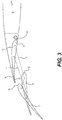
- Figure 3 shows a schematic section through the trailing edge region of the wing of the vehicle shown in Figures 1 and 2 showing the relative positions of the wing 16 and a trailing edge flap 30.
- the flap 30 is mounted on the underside of the trailing edge region of the wing 16.
- the flap 30 is moveable between a first position A and a second position C via a range of intermediate positions B.
- the flap 30 in the first position A the flap 30 is substantially aligned with the wing 16, the trailing edge 33 of the flap 30 lying under the trailing edge 34 of the wing 16.
- the flap 30 In the intermediate positions B, the flap 30 is displaced rearwardly from the wing 16.
- the plane of the flap 30 is lowered with respect to that of the wing 16, and the angle of attack of the flap is substantially similar to that of the wing.
- the flap 30 In the second position C, the flap 30 is further displaced behind and below the wing and has an angle of attack greater than that of the wing.
- Figure 4 shows a partial view of the operating mechanism used to move the flap 30 between positions A, B, and C (parts are omitted for clarity).
- the operating mechanism comprises first and second struts 36, 38, extending between the wing 16 and the flap 30.
- Each strut 36, 38 has a curved or arcuate shape and is provided with a toothed rack 40, 42 on its concave surface.
- the distribution of teeth on the first rack is substantially equidistant.
- the distribution of teeth on the second rack is non-equidistant.
- First and second guide members 44, 46 project from the side of the forward part of the first strut 36 for engagement in guide tracks (not shown) as is described below. Corresponding guide members are also provided on the second strut 38.
- the first strut 36 is connected near the leading edge 32 of the flap 30 by means of a pivot connection 48.
- the second strut 38 is connected to the flap 30 by a corresponding pivot connection 50 at a portion closer to the trailing edge 33 of the flap 30 than the first connection 48.
- a toothed pinion 52 is mounted in the wing 16 for rotation about an axis extending in the span direction of the wing.
- the pinion 52 engages the toothed racks 40, 42. Rotation of the pinion 52 acts on the toothed racks 40, 42 and causes the struts 36, 38 to extend or retract together, moving the flap accordingly.
- Figure 5 shows the operating mechanism from the opposite side to that shown in Figure 4 .
- the second strut 38 has first and second guide members 54, 56 corresponding to the first strut guide members 44, 46 shown in Figure 4 .
- Each guide member 44, 46, 54, 56 engages in corresponding guide rails 58, 60, 62, 64 which define tracks constraining the range of movement of each guide member 44, 46, 54, 56 to a respective predetermined path.
- the shape of each pair of guide rails 58, 60, and 62, 64 is configured to provide predetermined ranges of movement of the flap connections 48, 50 in both dimensions of a vertical plane containing a chord of the wing as the struts 36, 38 extend or retract on operation of the pinion.
- the guide rails 58, 60, 52, 54 are fixed to the wing structure (not shown).
- Figures 6A-F show the relative positions of the flap 30 and wing 16 as the operating mechanism moves the flap 30 between the first position ( Figure 6 A) , intermediate positions ( Figures 6B-E ), and second position ( Figure 6 F) .
- FIG. 6A-F shows the relative positions of the flap 30, first and second struts 36, 38, the first and second flap connections 48, 50, and the positions of the guide members 44, 46, 54, 56 in their respective guide rails 58, 60, 62, 64.
- the wing 16 is shown in outline for reference.
- FIG 6A shows the flap 30 in the first position (position A of Figure 3 ).
- the struts 36, 38 are in their most retracted position with the pinion at the rear end of the racks 40, 42.
- the guide members 44, 46, 54, 56 lie at the front ends of respective guide rails 58, 60, 62, 64.
- Driving the pinion 52 in an anti-clockwise direction causes the struts to begin to extend and displace the flap 16.
- Figure 6B shows the flap 30 in an early stage of deployment in an intermediate position (position B of Figure 3 ).
- the shapes of the racks 40, 42, and of the guide rails 58, 60, 62, 64 mean that the flap 30 drops below the lower surface of the wing 16, and the trailing edge 33 of the flap 30 extends behind the trailing edge 34 of the wing 16. In this position, the angle of attack of the flap 30 is about 2 degrees greater than that of the wing 16.
- the racks 40, 42, and guide rails 58, 60, 62, 64 cause the first strut 36 to move more than the second strut 38, causing the angle of attack to increase to about 35 degrees ( Figure 6 F) .
- the struts 36, 38 are fully extended, the pinion being at the front end of each rack 40, 42.
- the main effect during this change of operation is to increase the angle of attack of the wing and flap combination.
- Lines X and Y on Figure 3 show the trajectories of the first and second flap connections 48, 50 as the struts 36, 38 extend..
- the trajectories are approximately linear and converge slightly, hence the lateral deployment with only a small change in the angle of attack.
- the trajectories diverge relatively raising the first connection 48 and lowering the second connection 50, thus effecting the main change in the angle of attack of the flap 30.
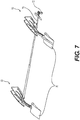
- FIG 7 shows the flap system with two operating mechanisms 80, 90. Each mechanism is substantially as described in relation to Figures 4 - 6 . Only the part of the flap 30 connected to each mechanism 80, 90 is shown.
- each mechanism 80, 90 is mounted on a common shaft 70 which is provided with a releasable connection 72 by which the shaft 70 can be connected to a drive motor located in the aircraft body (not shown).
- a drive motor located in the aircraft body (not shown).
- the connection 72 By locating the connection 72 near the wing root, the drive can be connected or disconnected to allow wing folding.
- the system can be configured such that the connection 72 can only be made or broken when the flap is in the first position. This can help avoid damage to the flap during wing folding.
- a universal joint or constant velocity joint can be provided in the shaft drive system to accommodate alignment issues when connecting the systems.
- one of the mechanisms can be passive, with no drive to the pinion, and the mechanism merely acts to control the movement of the flap under the influence of the active mechanism.
- the exact shapes of the guide rails, struts, and racks can be selected to achieve the desired range of movements. Other changes are also possible.
Abstract
Description
- This invention relates to a flap system for use on an aircraft. In particular, it relates to such a system for use on a convertible vehicle that is configurable for both road and flight use, sometimes called a "flying car".
- Flaps, such as deployable trailing edge flaps, are structures used to adjust the aerodynamic properties of a wing, typically to change its lift characteristics. By extending trailing edge flaps, the wing can be adapted to operate more effectively in low speed situations, such as takeoff and landing, typically to decrease the stall speed of the wing. When the aircraft is properly airborne and flying, the flaps can be retracted to increase the efficiency of the wing and reduce drag.
- There are various types of trailing edge flap systems. One type, known as a Fowler flap system, involves a two-stage movement of the flap as it is extended. In a first stage, the flap extends mainly laterally from the trailing edge of the wing with little or no change of angle of attack with respect to the wing itself. The effect of this is to extend the chord length (distance from the leading edge of the wing to the trailing edge of the flap in the direction of travel) of the whole wing and flap structure. In a second stage, the angle of attack of the flap with respect to the wing is increased, leading to an overall increase in the angle of attack of the wing and flap structure.
- There have been a number of previous proposals for flying car designs, i.e. vehicles that can be fully compliant with legal and practical requirements for both road and flight use. Examples include the Terrafugia Transition (
WO 2007/114877 ) and the AeroMobil (WO 2013/032409 ,WO 2016/057003 ,WO 2016/057004 ). - The space available within the wings of these vehicles for actuators and operating mechanisms is limited. In addition, it is usually necessary that operational controls between the body and the wing structure be capable of being disconnected for wing folding to take place.
- The invention aims to provide a wing and flap system that addresses at least some of these considerations.
- A first aspect provides a wing and flap system for an aircraft, comprising: a wing; and a deployable flap connected to the wing, the flap being moveable between a first position in which a trailing edge portion of the wing substantially overlaps the flap and the angle of incidence of the flap is substantially the same as the angle of incidence of the wing, and a second position in which the trailing edge of the flap is behind the trailing edge of the wing and the angle of incidence of the flap is greater than that of the wing, and an intermediate position between the first and second positions, in which the trailing edge of the flap is behind the trailing edge of the wing and the angle of incidence of the flap is substantially the same as that of the wing; and further comprising a flap operating mechanism for moving the flap between the first, second, and intermediate positions, comprising: a driven toothed pinion mounted in the wing; and first and second struts, each substantially aligned with a plane including a chord of the wing and extending between the pinion and the flap, each strut having a toothed rack engaged with the toothed pinion such that operation of the pinion moves each strut in a direction substantially aligned with a plane including a chord of the wing, the first strut being connected to the flap relatively closer to the leading edge thereof, and the second strut being connected to the flap relatively closer to the trailing edge thereof.
- For example, the first position can have an angle of attack that is in the range 0 - 10 degrees with respect to the angle of attack of the wing and the second position can have an angle of attack that is greater than 10 degrees with respect to the angle of attack of the wing, optionally up to at least 35 degrees with respect to the angle of attack of the wing.
- The driven toothed pinion can be mounted for rotation about an axis substantially aligned with the span of the wing.
- Each rack can be a curved or arcuate rack such that operation of the pinion moves the connection to the flap in both dimensions of the respective plane that includes a chord of the wing. In this way the drive input from the pinion can be from a fixed position. The first and second struts can have different curved or arcuate racks. In this way a single drive input can vary both the lateral displacement of the flap from the wing and the angle of attack of the flap. The rack on the first strut can have an equidistant distribution of teeth, and the rack on the second strut can have a non-equidistant distribution of teeth. In this way the velocities of the connections of the struts to the flap can be made to vary.
- Each strut can further comprise guide members that engage in guide tracks connected to the wing to constrain the movement of the rack when the pinion is operated. Each strut can have at least two guide members, each guide member engaging in a respective guide track, and each respective guide track defining a different path of movement for its respective guide member.
- The system can comprise at least two operating mechanisms spaced along the span of the wing, the pinion of each mechanism being defined on a common shaft. Providing drive to the pinion of each operating mechanism can help avoid jamming due to distortion of components.
- The pinion can be provided with a separable connection to be connectable to a motor located in a body of an aircraft to which the wing and flap system is connected.
- Another aspect provides an aircraft comprising a convertible vehicle having a flight configuration and a road use configuration, the aircraft comprising a body; wheels for supporting, driving and steering the aircraft in a road use configuration; and a pair of wings connected to the body by a mounting structure, the wings being movable between an extended position in which the wings extend laterally from the body for a flight configuration, and a folded position in which the wings extend along the body from the mounting structure for a road use configuration; wherein the wings comprise the wing and flap system.
- At least one motor can be located in the body that is controllable to move the flaps between the first, second, and intermediate positions when in the flight configuration.
- The wing and flap system can be configured such that movement from the extended position to the folded position only takes place when the flaps are in the first position. This can help avoid damage to the flaps when the trailing edges of the wings are positioned close to other structures when in the folded position.
- Further variations can be made within the scope of the invention.
-
Figure 1 shows a front perspective view of a flying car in a flight configuration; -
Figure 2 shows a front perspective view of a flying car in a road use configuration; -
Figure 3 shows a schematic view through the trailing edge regions of a wing of the flying car ofFigures 1 and 2 ; -
Figure 4 shows a partial view of an operating mechanism; -
Figure 5 shows another view of an operating mechanism; -
Figures 6A - F show the relative positions of various parts as a flap moves from a first to a second position; and -
Figure 7 shows a flap system with two operating mechanisms. - Referring to
Figures 1 and 2 , an aircraft comprising a convertible vehicle (a flying car) is shown, in a flight configuration (Figure 1 ) and a road use configuration (Figure 2 ). The flying car comprises abody structure 10 providing acrew compartment 12 and housing a motor (not shown) and propeller shaft (not shown) that extends from the motor to the rear 14 of thebody structure 10, where the propeller is mounted as is described below.Wings 16 for providing lift and control (via ailerons, not shown) are mounted at the top of thebody 10 immediately behind thecrew compartment 12. Thewings 16 are connected to a mounting structure (not shown) positioned within thebody 10 beneath a moveable cover 17. Thewings 16 can be moved between an extended position for flight use (Figure 1 ), and a folded position for road use (Figure 2 ). In the folded position, the wings lie along the top of thebody 10, the long axes of the wings lying substantially parallel to the long axis of thebody 10. - A
tail structure 18 is located at the rear of thebody 10, and includes vertical control surfaces 20 (fins and rudders), and horizontal control surfaces 22 (tail planes and elevators).Rear wheels 24 are provided at the lower ends of thefins 20. -
Front wheels 26 are mounted on thebody structure 10. The front wheels are both steerable and driven. In addition, thefront wheels 26 can be moved between a retracted position (Figure 1 ) in which they are positioned close to the body to reduce drag in flight, and an open position (Figure 2 ) in which they are positioned for improved traction and control for road use. - When the
wings 16 are folded back to lie along the rear of thebody 14, the trailing edge part of one wing lies over the corresponding trailing edge part of the other wing. When folded in this way, the overall width of the folded wings lies within the lateral extremities of the vehicle as defined, for example, by the wheels when extended in the road use configuration. Furthermore, the width of the folded arrangement is such that the wings fit between the upper parts of the tailvertical control surfaces 20, and the wing tips are adjacent the tailhorizontal control surfaces 22. -
Figure 3 shows a schematic section through the trailing edge region of the wing of the vehicle shown inFigures 1 and 2 showing the relative positions of thewing 16 and atrailing edge flap 30. - The
flap 30 is mounted on the underside of the trailing edge region of thewing 16. Theflap 30 is moveable between a first position A and a second position C via a range of intermediate positions B. in the first position A theflap 30 is substantially aligned with thewing 16, thetrailing edge 33 of theflap 30 lying under thetrailing edge 34 of thewing 16. In the intermediate positions B, theflap 30 is displaced rearwardly from thewing 16. The plane of theflap 30 is lowered with respect to that of thewing 16, and the angle of attack of the flap is substantially similar to that of the wing. In the second position C, theflap 30 is further displaced behind and below the wing and has an angle of attack greater than that of the wing. -
Figure 4 shows a partial view of the operating mechanism used to move theflap 30 between positions A, B, and C (parts are omitted for clarity). - The operating mechanism comprises first and
second struts wing 16 and theflap 30. Eachstrut toothed rack second guide members first strut 36 for engagement in guide tracks (not shown) as is described below. Corresponding guide members are also provided on thesecond strut 38. - The
first strut 36 is connected near the leadingedge 32 of theflap 30 by means of apivot connection 48. Thesecond strut 38 is connected to theflap 30 by acorresponding pivot connection 50 at a portion closer to the trailingedge 33 of theflap 30 than thefirst connection 48. - A
toothed pinion 52 is mounted in thewing 16 for rotation about an axis extending in the span direction of the wing. Thepinion 52 engages thetoothed racks pinion 52 acts on thetoothed racks struts -
Figure 5 shows the operating mechanism from the opposite side to that shown inFigure 4 . - The
second strut 38 has first andsecond guide members strut guide members Figure 4 . Eachguide member corresponding guide rails guide member guide rails flap connections struts -
Figures 6A-F show the relative positions of theflap 30 andwing 16 as the operating mechanism moves theflap 30 between the first position (Figure 6 A) , intermediate positions (Figures 6B-E ), and second position (Figure 6 F) . - Each of
Figures 6A-F shows the relative positions of theflap 30, first andsecond struts second flap connections guide members respective guide rails wing 16 is shown in outline for reference. -
Figure 6A shows theflap 30 in the first position (position A ofFigure 3 ). Thestruts racks guide members respective guide rails pinion 52 in an anti-clockwise direction causes the struts to begin to extend and displace theflap 16. -
Figure 6B shows theflap 30 in an early stage of deployment in an intermediate position (position B ofFigure 3 ). The shapes of theracks flap 30 drops below the lower surface of thewing 16, and the trailingedge 33 of theflap 30 extends behind the trailingedge 34 of thewing 16. In this position, the angle of attack of theflap 30 is about 2 degrees greater than that of thewing 16. - Further operation of the mechanism continues to extend the
struts Figure 6C : five degrees;Figure 6 D: eight degrees;Figure 6 E: 10 degrees) as theflap 30 moves through the range of intermediate positions. The main effect during this stage of operation is to increase the chord length of the wing and flap combination, with a relatively small change of angle of attack of the wing and flap combination. - In the final stage of movement, the
racks guide rails first strut 36 to move more than thesecond strut 38, causing the angle of attack to increase to about 35 degrees (Figure 6 F) . At this point thestruts rack - Reversing the drive of the
pinion 52 reverses the sequence of movements and retracts theflap 30 into thewing 16. - Lines X and Y on
Figure 3 show the trajectories of the first andsecond flap connections struts Figures 6A - E ), the trajectories are approximately linear and converge slightly, hence the lateral deployment with only a small change in the angle of attack. In the final phase of deployment (Figure 6 F) , the trajectories diverge relatively raising thefirst connection 48 and lowering thesecond connection 50, thus effecting the main change in the angle of attack of theflap 30. -
Figure 7 shows the flap system with two operatingmechanisms Figures 4 - 6 . Only the part of theflap 30 connected to eachmechanism - The pinion of each
mechanism common shaft 70 which is provided with areleasable connection 72 by which theshaft 70 can be connected to a drive motor located in the aircraft body (not shown). By locating theconnection 72 near the wing root, the drive can be connected or disconnected to allow wing folding. By providing an appropriate indexing system in the connection, the system can be configured such that theconnection 72 can only be made or broken when the flap is in the first position. This can help avoid damage to the flap during wing folding. A universal joint or constant velocity joint can be provided in the shaft drive system to accommodate alignment issues when connecting the systems. - By providing two substantially identical systems and a common drive shaft, the possibility of jamming due to distortion can be reduced.
- Various changes can be made to the system disclosed above and in the claims. For example, where two mechanisms are provided, one of the mechanisms can be passive, with no drive to the pinion, and the mechanism merely acts to control the movement of the flap under the influence of the active mechanism. The exact shapes of the guide rails, struts, and racks can be selected to achieve the desired range of movements. Other changes are also possible.
Claims (13)
- A wing and flap system for an aircraft, comprising:a wing; anda deployable flap connected to the wing, the flap being moveable betweena first position in which a trailing edge portion of the wing substantially overlaps the flap and the angle of incidence of the flap is substantially the same as the angle of incidence of the wing, anda second position in which the trailing edge of the flap is behind the trailing edge of the wing and the angle of incidence of the flap is greater than that of the wing, andan intermediate position between the first and second positions, in which the trailing edge of the flap is behind the trailing edge of the wing and the angle of incidence of the flap is substantially the same as that of the wing;and further comprising a flap operating mechanism for moving the flap between the first, second, and intermediate positions, comprising:a driven toothed pinion mounted in the wing; andfirst and second struts, each substantially aligned with a plane including a chord of the wing and extending between the pinion and the flap, each strut having a toothed rack engaged with the toothed pinion such that operation of the pinion moves each strut in a direction substantially aligned with a plane including a chord of the wing, the first strut being connected to the flap relatively closer to the leading edge thereof, and the second strut being connected to the flap relatively closer to the trailing edge thereof.
- A system as claimed in claim 1, wherein the driven toothed pinion is mounted for rotation about an axis substantially aligned with the span of the wing.
- A system as claimed in claim 1 or 2, wherein each rack is a curved or arcuate rack such that operation of the pinion moves the connection to the flap in both dimensions of the respective plane that includes a chord of the wing.
- A system as claimed in claim 3, wherein the first and second struts have different curved or arcuate racks.
- A system as claimed in claim 4, wherein the rack on the first strut has an equidistant distribution of teeth, and the rack on the second strut has a non-equidistant distribution of teeth.
- A system as claimed in any preceding claim, wherein each strut further comprises guide members that engage in guide tracks connected to the wing to constrain the movement of the rack when the pinion is operated.
- A system as claimed in claim 5, wherein each strut has at least two guide members, each guide member engaging in a respective guide track, and each respective guide track defining a different path of movement for its respective guide member.
- A system as claimed in any preceding claim, comprising at least two operating mechanisms spaced along the span of the wing, the pinion of each mechanism being defined on a common shaft.
- A system as claimed in any preceding claim, wherein the pinion is provided with a separable connection to be connectable to a motor located in a body of an aircraft to which the wing and flap system is connected.
- A system as claimed in any preceding claim, wherein the first position has an angle of attack that is in the range 0 - 10 degrees with respect to the angle of attack of the wing and the second position has an angle of attack that is greater than 10 degrees with respect to the angle of attack of the wing, optionally up to at least 35 degrees with respect to the angle of attack of the wing.
- An aircraft comprising a convertible vehicle having a flight configuration and a road use configuration, the aircraft comprising a body; wheels for supporting, driving and steering the aircraft in a road use configuration; and a pair of wings connected to the body by a mounting structure, the wings being movable between an extended position in which the wings extend laterally from the body for a flight configuration, and a folded position in which the wings extend along the body from the mounting structure for a road use configuration; wherein the wings comprise a wing and flap system as claimed in any preceding claim.
- An aircraft as claimed in claim 11, further comprising at least one motor located in the body that is controllable to move the flaps between the first, second, and intermediate positions when in the flight configuration.
- An aircraft as claimed in claim 12, wherein the wing and flap system is configured such that movement from the extended position to the folded position only takes place when the flaps are in the first position.
Priority Applications (2)
| Application Number | Priority Date | Filing Date | Title |
|---|---|---|---|
| EP17176991.2A EP3418184A1 (en) | 2017-06-20 | 2017-06-20 | Wing flap system for flying car |
| PCT/EP2018/065525 WO2018234104A1 (en) | 2017-06-20 | 2018-06-12 | Wing flap system for flying car |
Applications Claiming Priority (1)
| Application Number | Priority Date | Filing Date | Title |
|---|---|---|---|
| EP17176991.2A EP3418184A1 (en) | 2017-06-20 | 2017-06-20 | Wing flap system for flying car |
Publications (1)
| Publication Number | Publication Date |
|---|---|
| EP3418184A1 true EP3418184A1 (en) | 2018-12-26 |
Family
ID=59093472
Family Applications (1)
| Application Number | Title | Priority Date | Filing Date |
|---|---|---|---|
| EP17176991.2A Withdrawn EP3418184A1 (en) | 2017-06-20 | 2017-06-20 | Wing flap system for flying car |
Country Status (2)
| Country | Link |
|---|---|
| EP (1) | EP3418184A1 (en) |
| WO (1) | WO2018234104A1 (en) |
Citations (7)
| Publication number | Priority date | Publication date | Assignee | Title |
|---|---|---|---|---|
| DE738636C (en) * | 1940-03-21 | 1943-08-25 | Arado Flugzeugwerke G M B H | Airplane wing with sliding and rotating lift flaps |
| US4725026A (en) * | 1985-07-31 | 1988-02-16 | Deutsche Airbus Gmbh | Wing with extendable flap and variable camber |
| US5230487A (en) * | 1991-03-08 | 1993-07-27 | Deutsche Aerospace Airbus Gmbh | Apparatus for driving and guiding a flap secured to an aircraft wing |
| WO2007114877A2 (en) | 2006-01-06 | 2007-10-11 | Terrafugia, Inc. | Roadable aircraft with folding wings and integrated bumpers and lighting |
| WO2013032409A1 (en) | 2011-08-30 | 2013-03-07 | Aeromobil, S.R.O. | Transformation method of hybrid transportation vehicle for ground and air, and hybrid transportation vehicle itself |
| WO2016057004A1 (en) | 2014-10-08 | 2016-04-14 | Aeromobil, S.R.O. | Central wing panel for a flying vehicle and method of its control |
| WO2016057003A2 (en) | 2014-10-08 | 2016-04-14 | Aeromobil, S.R.O. | A directional control system and method for a hybrid air and ground transportation vehicle |
-
2017
- 2017-06-20 EP EP17176991.2A patent/EP3418184A1/en not_active Withdrawn
-
2018
- 2018-06-12 WO PCT/EP2018/065525 patent/WO2018234104A1/en active Application Filing
Patent Citations (7)
| Publication number | Priority date | Publication date | Assignee | Title |
|---|---|---|---|---|
| DE738636C (en) * | 1940-03-21 | 1943-08-25 | Arado Flugzeugwerke G M B H | Airplane wing with sliding and rotating lift flaps |
| US4725026A (en) * | 1985-07-31 | 1988-02-16 | Deutsche Airbus Gmbh | Wing with extendable flap and variable camber |
| US5230487A (en) * | 1991-03-08 | 1993-07-27 | Deutsche Aerospace Airbus Gmbh | Apparatus for driving and guiding a flap secured to an aircraft wing |
| WO2007114877A2 (en) | 2006-01-06 | 2007-10-11 | Terrafugia, Inc. | Roadable aircraft with folding wings and integrated bumpers and lighting |
| WO2013032409A1 (en) | 2011-08-30 | 2013-03-07 | Aeromobil, S.R.O. | Transformation method of hybrid transportation vehicle for ground and air, and hybrid transportation vehicle itself |
| WO2016057004A1 (en) | 2014-10-08 | 2016-04-14 | Aeromobil, S.R.O. | Central wing panel for a flying vehicle and method of its control |
| WO2016057003A2 (en) | 2014-10-08 | 2016-04-14 | Aeromobil, S.R.O. | A directional control system and method for a hybrid air and ground transportation vehicle |
Also Published As
| Publication number | Publication date |
|---|---|
| WO2018234104A1 (en) | 2018-12-27 |
Similar Documents
| Publication | Publication Date | Title |
|---|---|---|
| CN103786871B (en) | Hinged tilting wing tip | |
| US3941334A (en) | Variable camber airfoil | |
| CN101309832B (en) | Aircraft trailing edge devices, including devices with non-parallel motion paths, and associated methods | |
| CN109415116B (en) | Assembly and method for deploying a trailing edge flap of an aircraft | |
| US8393570B2 (en) | Landing flap kinematics driven by way of a pinion drive | |
| US3904152A (en) | Variable area, variable camber wing for aircraft | |
| US10611459B2 (en) | Central wing panel for a flying vehicle and method of its control | |
| EP3584154B1 (en) | Aircraft wing with deployable flap | |
| EP3301018A1 (en) | System for driving and guiding of a multifunctional trailing edge control surface on an aircraft | |
| EP2886451A1 (en) | Trailing-edge flap system for a wing of an aircraft and aircraft comprising a wing and at least one such trailing-edge flap system | |
| EP3498596A1 (en) | Actuating mechanism for trailing edge flaps and leading edge slats | |
| ES2746872T3 (en) | Wing system of an aircraft | |
| EP3763620B1 (en) | Flap actuation system for aircraft | |
| US4365774A (en) | Convertible delta wing aircraft | |
| EP3412560A1 (en) | Wing folding | |
| EP2746151B1 (en) | Flap system for an aircraft, method for adjusting the lift of an aircraft and aircraft comprising a main wing and at least one flap system | |
| EP3418184A1 (en) | Wing flap system for flying car | |
| US11492098B2 (en) | High-lift device, wing, and aircraft | |
| EP3560821B1 (en) | A control surface actuation mechanism | |
| EP3301017A1 (en) | System for driving and guiding of a trailing edge control surface | |
| EP3366570A1 (en) | Wing folding | |
| EP4303122A1 (en) | Wing for an aircraft | |
| CN109895995A (en) | A kind of wing flap control mechanism of light-duty sport plane | |
| EP4342790A1 (en) | Flight control surface | |
| EP3453610B1 (en) | Wing assembly with a main wing and a high-lift system |
Legal Events
| Date | Code | Title | Description |
|---|---|---|---|
| PUAI | Public reference made under article 153(3) epc to a published international application that has entered the european phase |
Free format text: ORIGINAL CODE: 0009012 |
|
| AK | Designated contracting states |
Kind code of ref document: A1 Designated state(s): AL AT BE BG CH CY CZ DE DK EE ES FI FR GB GR HR HU IE IS IT LI LT LU LV MC MK MT NL NO PL PT RO RS SE SI SK SM TR |
|
| AX | Request for extension of the european patent |
Extension state: BA ME |
|
| 17P | Request for examination filed |
Effective date: 20190626 |
|
| RBV | Designated contracting states (corrected) |
Designated state(s): AL AT BE BG CH CY CZ DE DK EE ES FI FR GB GR HR HU IE IS IT LI LT LU LV MC MK MT NL NO PL PT RO RS SE SI SK SM TR |
|
| GRAP | Despatch of communication of intention to grant a patent |
Free format text: ORIGINAL CODE: EPIDOSNIGR1 |
|
| INTG | Intention to grant announced |
Effective date: 20200421 |
|
| STAA | Information on the status of an ep patent application or granted ep patent |
Free format text: STATUS: THE APPLICATION IS DEEMED TO BE WITHDRAWN |
|
| 18D | Application deemed to be withdrawn |
Effective date: 20200902 |