EP3203819A1 - Entfeuchtungsvorrichtung für ein gehäuse - Google Patents
Entfeuchtungsvorrichtung für ein gehäuse Download PDFInfo
- Publication number
- EP3203819A1 EP3203819A1 EP16199797.8A EP16199797A EP3203819A1 EP 3203819 A1 EP3203819 A1 EP 3203819A1 EP 16199797 A EP16199797 A EP 16199797A EP 3203819 A1 EP3203819 A1 EP 3203819A1
- Authority
- EP
- European Patent Office
- Prior art keywords
- dehumidifying
- housing
- chamber
- dehumidifying device
- dehumidifying chamber
- Prior art date
- Legal status (The legal status is an assumption and is not a legal conclusion. Google has not performed a legal analysis and makes no representation as to the accuracy of the status listed.)
- Granted
Links
Images

Classifications
-
- H—ELECTRICITY
- H05—ELECTRIC TECHNIQUES NOT OTHERWISE PROVIDED FOR
- H05K—PRINTED CIRCUITS; CASINGS OR CONSTRUCTIONAL DETAILS OF ELECTRIC APPARATUS; MANUFACTURE OF ASSEMBLAGES OF ELECTRICAL COMPONENTS
- H05K5/00—Casings, cabinets or drawers for electric apparatus
- H05K5/02—Details
- H05K5/0213—Venting apertures; Constructional details thereof
- H05K5/0215—Venting apertures; Constructional details thereof with semi-permeable membranes attached to casings
-
- B—PERFORMING OPERATIONS; TRANSPORTING
- B01—PHYSICAL OR CHEMICAL PROCESSES OR APPARATUS IN GENERAL
- B01D—SEPARATION
- B01D53/00—Separation of gases or vapours; Recovering vapours of volatile solvents from gases; Chemical or biological purification of waste gases, e.g. engine exhaust gases, smoke, fumes, flue gases, aerosols
- B01D53/26—Drying gases or vapours
- B01D53/261—Drying gases or vapours by adsorption
-
- B—PERFORMING OPERATIONS; TRANSPORTING
- B01—PHYSICAL OR CHEMICAL PROCESSES OR APPARATUS IN GENERAL
- B01D—SEPARATION
- B01D53/00—Separation of gases or vapours; Recovering vapours of volatile solvents from gases; Chemical or biological purification of waste gases, e.g. engine exhaust gases, smoke, fumes, flue gases, aerosols
- B01D53/26—Drying gases or vapours
- B01D53/268—Drying gases or vapours by diffusion
-
- B—PERFORMING OPERATIONS; TRANSPORTING
- B65—CONVEYING; PACKING; STORING; HANDLING THIN OR FILAMENTARY MATERIAL
- B65D—CONTAINERS FOR STORAGE OR TRANSPORT OF ARTICLES OR MATERIALS, e.g. BAGS, BARRELS, BOTTLES, BOXES, CANS, CARTONS, CRATES, DRUMS, JARS, TANKS, HOPPERS, FORWARDING CONTAINERS; ACCESSORIES, CLOSURES, OR FITTINGS THEREFOR; PACKAGING ELEMENTS; PACKAGES
- B65D81/00—Containers, packaging elements, or packages, for contents presenting particular transport or storage problems, or adapted to be used for non-packaging purposes after removal of contents
- B65D81/24—Adaptations for preventing deterioration or decay of contents; Applications to the container or packaging material of food preservatives, fungicides, pesticides or animal repellants
- B65D81/26—Adaptations for preventing deterioration or decay of contents; Applications to the container or packaging material of food preservatives, fungicides, pesticides or animal repellants with provision for draining away, or absorbing, or removing by ventilation, fluids, e.g. exuded by contents; Applications of corrosion inhibitors or desiccators
- B65D81/266—Adaptations for preventing deterioration or decay of contents; Applications to the container or packaging material of food preservatives, fungicides, pesticides or animal repellants with provision for draining away, or absorbing, or removing by ventilation, fluids, e.g. exuded by contents; Applications of corrosion inhibitors or desiccators for absorbing gases, e.g. oxygen absorbers or desiccants
-
- H—ELECTRICITY
- H02—GENERATION; CONVERSION OR DISTRIBUTION OF ELECTRIC POWER
- H02K—DYNAMO-ELECTRIC MACHINES
- H02K11/00—Structural association of dynamo-electric machines with electric components or with devices for shielding, monitoring or protection
- H02K11/30—Structural association with control circuits or drive circuits
-
- H—ELECTRICITY
- H02—GENERATION; CONVERSION OR DISTRIBUTION OF ELECTRIC POWER
- H02K—DYNAMO-ELECTRIC MACHINES
- H02K5/00—Casings; Enclosures; Supports
- H02K5/04—Casings or enclosures characterised by the shape, form or construction thereof
-
- H—ELECTRICITY
- H02—GENERATION; CONVERSION OR DISTRIBUTION OF ELECTRIC POWER
- H02K—DYNAMO-ELECTRIC MACHINES
- H02K9/00—Arrangements for cooling or ventilating
-
- H—ELECTRICITY
- H05—ELECTRIC TECHNIQUES NOT OTHERWISE PROVIDED FOR
- H05K—PRINTED CIRCUITS; CASINGS OR CONSTRUCTIONAL DETAILS OF ELECTRIC APPARATUS; MANUFACTURE OF ASSEMBLAGES OF ELECTRICAL COMPONENTS
- H05K5/00—Casings, cabinets or drawers for electric apparatus
- H05K5/02—Details
- H05K5/0212—Condensation eliminators
Definitions
- the invention relates to a dehumidifying device for a housing, in particular an electronics housing of an electric motor and the electronics housing and the electric motor with such a dehumidifying device.
- the invention is therefore an object of the invention to provide a dehumidifying device for housing, in particular electronics housing of electric motors, which is inexpensive to implement and long-term stability.
- a dehumidifying device for a housing having a dehumidifying chamber having a wall, within which hygroscopic material is accommodated.
- the hygroscopic material is designed to bind humidity from the dehumidification chamber.
- the wall of the dehumidifying chamber has at least one inner vapor-permeable membrane, which can be brought into operative connection with a receiving interior of the housing, and an outer membrane, which can be brought into operative connection with the outside environment of the housing.
- the inner and outer membranes are each vapor permeable in at least the direction in which a transport of moisture moisture from the receiving interior of the housing through the dehumidifying chamber in the outside environment can be ensured.
- the dehumidifying By using the dehumidifying a complex sealing of the housing is not necessary. Rather, it is made possible that the moisture from the receiving interior of the housing is diffused through the inner membrane into the dehumidifying chamber and bound there by the hygroscopic material. Due to the naturally always desired saturation equilibrium It diffuses moisture in the form of vapor into the dehumidifying chamber until a vapor pressure equilibrium prevails. At the same time, a moisture release into the outside environment is made possible via the outer membrane, so that the water absorption capacity of the hygroscopic material remains permanently ensured.
- the dehumidifying system according to the invention works with bidirectionally permeable membranes as long as the humidity in the outside environment is lower than in the dehumidifying room.
- At least the outer membrane is water impermeable. This ensures that no excess moisture can enter the dehumidification chamber from the outside environment, which could saturate the hygroscopic material with water.
- the inner and outer membranes can each be designed semipermeable.
- the inner membrane is unidirectionally vapor permeable to the dehumidifying chamber, i. from the receiving interior into the dehumidifying chamber.
- the outer membrane is unidirectionally vapor permeable from the dehumidification chamber, i. out of the dehumidification chamber to the outside environment. Ingress of moisture from the outside environment into the dehumidifying chamber is thus ruled out, even if the absolute humidity in the outside environment is secondarily greater than in the dehumidifying room.
- the inner membrane has a lower moisture permeability than the outer membrane.
- the higher moisture permeability of the outer membrane adjacent the outer membrane tends to increase the vapor permeability to the outside such that at high water saturation the hygroscopic material favors drying and evaporation in the outside environment.
- the wall of the dehumidifying chamber is formed by the inner and outer membranes.
- the inner and outer membranes enclose the hygroscopic material and themselves completely form the transitions between the receiving interior and the outside environment.
- the two membranes can, for example, be sewn, glued or otherwise fastened together at their edge sections, it always being provided that the inner membrane faces the receiving interior and the outer membrane faces the outer environment.
- the hygroscopic material is selected from materials with high water absorption capacity, in particular calcium chloride (CaCl 2 ), silica gel (SiO 2 ), calcium carbonate (K 2 CO 3 ) or zeolite.
- the inner and outer membranes are each formed in a variant of a high polymer membrane or a parchment membrane. Also included are embodiments in which the inner and outer membranes of nonwoven fabric, in particular polyethylene nonwoven fabric, or extruded polytetrafluoroethylene (PTFE) or polyethersulfone (PESU) are formed.
- the pore size of the membrane is preferably up to 40 nanometers. It is also possible to provide additional coatings on the membranes which promote unidirectional vapor permeability.
- the dehumidifying chamber can be heated.
- a heating wire is arranged, by means of which the dehumidifying chamber and the hygroscopic material located therein can be heated up.
- the moisture bound as water from the hygroscopic material be dissolved and transported over the increased by the resulting vapor partial pressure on the outer membrane in the outside environment.
- a heated dehumidifying chamber when a heated dehumidifying chamber is provided, a unidirectional inner membrane with an exclusive steam flow direction into the dehumidifying chamber is preferred.
- inner and outer membranes with different permeability can be used, in which the outer membrane provides less resistance and so the concentration and pressure gradient over the latter is compensated.
- the heating wire is designed as a hot wire.
- the hot wire is characterized in that it has a temperature-dependent change of the wire resistance, which in turn is measurable. By measuring the wire resistance can be achieved in a simple way, a control of the temperature or the desired heating cable.
- a moisture measuring sensor is arranged in the dehumidifying chamber.
- a humidity measuring device measuring the moisture saturation of the hygroscopic material is provided in the dehumidifying chamber.
- the moisture measuring device is realized in an embodiment by way of example by an electrical conductivity meter whose signals can be detected by a control unit. Consequently, a circuit can be realized in which the heating of the dehumidifying chamber or of the hygroscopic material is controlled as a function of a measured value of the absolute humidity in the dehumidifying space or the saturation of the hygroscopic material. Once a limit of water absorption is reached, the heater is used for drying.
- the dehumidifying chamber as exchangeable and / or retrofittable module unit is formed. It can thus be used on existing housing or simply replaced if necessary. It is also possible to adjust the dehumidifying capacity of the individual dehumidifying chambers to different degrees and to adapt the dehumidifying chambers to be used for the respective intended use. Thus, standard enclosures can be produced for all uses that can be equipped with different dehumidifiers.
- the invention further comprises housings, in particular an electronics housing of an electric motor, with a housing wall which at least partially encloses a receiving interior of the housing, wherein the receiving interior is designed to accommodate an engine electronics.
- the housing is characterized in that it is free of sealing relative to the environment and has a dehumidifying device described above.
- the invention comprises an electric motor with an engine electronics in an electronics housing, the engine electronics having a power module which is disposed adjacent to the dehumidifying device so that heat generated by the power module during operation of the electric motor is transferable to the dehumidifying device to heat the dehumidifying chamber.
- the heating of the dehumidifying chamber can thus be carried out without additional components, it is realized by the already used and sufficient heat generating power module. If the required temperature of the power module is not reached for a longer time, in one embodiment the power module is selectively controlled so that it heats up, but does not significantly change the function of the device.
- the module temperature of the power module is detected by a temperature sensor installed in the power module.
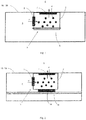
- FIG. 1 is a schematic view of a dehumidifying device 1 mounted in a housing 10, which may also serve as an electronics housing 100 of an electric motor shown.
- the dehumidifying device 1 has a dehumidifying chamber 3, in which hygroscopic material 4 is distributed at various locations. To increase the total surface area and thus to increase the water binding speed, the hygroscopic material 4 is distributed at several locations within the dehumidifying chamber 3.
- the inner vapor-permeable membrane 5 and adjacent to the outer environment 8 of the housing 10 adjacent to the receiving interior 6 of the housing 10, the outer vapor-permeable membrane 7 is provided.
- the inner and outer membranes 5, 7 each form a partial surface of the wall 2 of the dehumidifying chamber 3.
- the inner and outer membrane 5, 7 respectively permeable to vapor in the direction of arrow P and allow a transport of moisture moisture from the receiving interior 6 of the housing 10 through the dehumidifying chamber 3 in the outer environment 8.
- the vapor pressure gradient between the receiving interior 6 of the housing 10 and the interior of the dehumidifying chamber 3 is through generates the hygroscopic material 4.
- the absolute humidity within the dehumidifying chamber 3 due to the hygroscopic material 4 is lower than within the housing 10, so that via the inner membrane 5, a saturation and pressure equalization takes place.
- the humidity is bound by the hygroscopic material 4 as water. With heavy dehumidification, the absolute humidity within the dehumidifying chamber 3 can become greater than in the area of the external environment 8. Then moisture is released from the dehumidifying chamber 3 to the external environment 8 via the outer membrane 7.
- the inner and outer membranes 5, 7 are unidirectionally permeable in the direction of arrow P and impermeable to water.
- a heating wire 9 designed as a hot wire is arranged as a variant embodiment around the dehumidifying chamber 3. Via the heating wire 9, the dehumidifying chamber 3 and the hygroscopic material 4 located therein can be heated to such an extent that the bound water evaporates and the hygroscopic material 4 again has its full or essentially full water absorption coefficient w of the respective hygroscopic material.
- w m A ⁇ t m and A stand for mass and surface area of the hygroscopic material and t for the time.
- A stand for mass and surface area of the hygroscopic material and t for the time.
- absorbent materials with a value of the water absorption coefficient w > 2 kg / m 2 H 0 . 5 . for example, calcium chloride used.
- the inner and outer membranes 5, 7 are made of extruded PTFE and clamped in the wall 2 of the housing 10, 100 as a flat wall part.
- FIG. 2 has a dehumidifying chamber 3 with the features FIG. 1 so that it is renounced in this respect repetitions.
- the dehumidifying chamber 3 is arranged on a power module 11 of an engine electronics unit located on a printed circuit board 14. Both the printed circuit board 14 and the power module 11 are located within the receiving space 6 of the housing 10 or electronics housing 100.
- the power module 11 is selectively controllable, so that it can only generate heat without affecting the device function or engine function.
- the heat generation can be heated as an alternative embodiment of the heating wire, the dehumidifying chamber 3 and the hygroscopic material 4 are dried.
- the moisture transport also takes place in this embodiment according to the direction of arrow P from the receiving interior 6 to the outside environment. 8
- dehumidifying chamber 3 is shown schematically.
- the entire wall of the dehumidifying chamber 3 is formed by the inner and outer membrane 5, 7 itself. Between the inner and outer membrane 5, 7, the hygroscopic material 4 is received.
- the dehumidifying chamber 3 designed as a module unit 13 is fastened by means of corresponding receptacles 19 within the housing wall and separates the receiving space 6 to be dehumidified from the external environment 8, so that the moisture transport also takes place according to the arrow direction P in this embodiment.
- the invention is not limited in its execution to the above-mentioned preferred embodiments.
- membranes known on the market as well e.g. Tyvek (registered trademark), in particular type 16 are used, which meet the technical requirements of the vapor permeability according to the invention.
- the hygroscopic material in the dehumidifying chamber may also be wrapped with such material.
- Further alternatives for the membrane material are, for example, parchment or clay cells with inclusions of e.g. Copper hexacyanoferrate (II) or cellulose acetate.
Landscapes
- Engineering & Computer Science (AREA)
- Chemical & Material Sciences (AREA)
- Microelectronics & Electronic Packaging (AREA)
- Power Engineering (AREA)
- Analytical Chemistry (AREA)
- General Chemical & Material Sciences (AREA)
- Oil, Petroleum & Natural Gas (AREA)
- Chemical Kinetics & Catalysis (AREA)
- Food Science & Technology (AREA)
- Mechanical Engineering (AREA)
- Drying Of Gases (AREA)
- Separation Using Semi-Permeable Membranes (AREA)
Abstract
Description
- Die Erfindung betrifft eine Entfeuchtungsvorrichtung für ein Gehäuse, insbesondere ein Elektronikgehäuse eines Elektromotors sowie das Elektronikgehäuse und den Elektromotor mit einer derartigen Entfeuchtungsvorrichtung.
- Feuchtigkeit ist für elektronische Baugruppen schädlich. In Gehäusen bzw. Elektronikgehäusen werden deshalb vielfach Anstrengungen unternommen, um sowohl einen direkten Wassereintritt als auch eine Kondenswasserbildung durch Abdichtungsmaßnahmen zu verhindern. Vollständige Abdichtungen sind zwar technisch möglich, jedoch ist nicht ausgeschlossen, dass bei Temperaturschwankungen und dem damit einhergehenden wiederholten Ausdehnen und Zusammenziehen ungewollte Spalte entstehen, durch die Feuchtigkeit eindringen und der Elektronik schaden kann. Flexible Dichtungssysteme sind zwar ebenfalls bekannt, jedoch vergleichsweise aufwendig und teuer.
- Als bekannter Stand der Technik ist beispielhaft die Offenbarung der
WO 2013/079102 A1 zu nennen. - Der Erfindung liegt deshalb die Aufgabe zugrunde, eine Entfeuchtungsvorrichtung für Gehäuse, insbesondere Elektronikgehäuse von Elektromotoren bereitzustellen, die kostengünstig zu realisieren und langzeitbeständig ist.
- Diese Aufgabe wird durch die Merkmalskombination gemäß Patentanspruch 1 gelöst.
- Erfindungsgemäß wird eine Entfeuchtungsvorrichtung für ein Gehäuse, insbesondere ein Elektronikgehäuse eines Elektromotors vorgeschlagen, mit einer eine Wandung aufweisenden Entfeuchtungskammer, innerhalb der hygroskopisches Material aufgenommen ist. Das hygroskopische Material ist ausgebildet, Luftfeuchtigkeit aus der Entfeuchtungskammer zu binden. Die Wandung der Entfeuchtungskammer weist zumindest eine innere dampfdurchlässige Membran, die mit einem Aufnahmeinnenraum des Gehäuses in Wirkverbindung bringbar ist, und eine äußere Membran, die mit der Außenumgebung des Gehäuses in Wirkverbindung bringbar ist, auf. Die innere und äußere Membran sind jeweils in zumindest die Richtung dampfdurchlässig, bei der ein Luftfeuchtigkeitstransport aus dem Aufnahmeinnenraum des Gehäuses durch die Entfeuchtungskammer in die Außenumgebung gewährleistbar ist.
- Durch die Nutzung der Entfeuchtungsvorrichtung ist eine aufwendige Abdichtung des Gehäuses nicht nötig. Vielmehr wird ermöglicht, dass die Feuchtigkeit aus dem Aufnahmeinnenraum des Gehäuses durch die innere Membran in die Entfeuchtungskammer diffundiert und dort von dem hygroskopischen Material gebunden wird. Aufgrund des naturgemäß stets angestrebten Sättigungsgleichgewichts diffundiert so lange Feuchtigkeit in Form von Dampf in die Entfeuchtungskammer, bis ein Dampfdruckgleichgewicht herrscht. Gleichzeitig wird über die äußere Membran eine Feuchtigkeitsabgabe in die Außenumgebung ermöglicht, so dass die Wasseraufnahmefähigkeit des hygroskopischen Materials auf Dauer gewährleistet bleibt. Das erfindungsgemäße Entfeuchtungssystem funktioniert mit bidirektional permeablen Membranen, solange die Luftfeuchtigkeit in der Außenumgebung geringer ist als im Entfeuchtungsraum.
- In einer vorteilhaften Ausführungsvariante ist vorgesehen, dass zumindest die äußere Membran wasserundurchlässig ist. Hierdurch wird sichergestellt, dass aus der Außenumgebung keine übermäßige Feuchtigkeit in die Entfeuchtungskammer eindringen kann, wodurch das hygroskopische Material mit Wasser gesättigt werden könnte. Die innere und äußere Membran können hierzu jeweils semipermeabel ausgebildet sein.
- In einer Weiterbildung der Entfeuchtungsvorrichtung ist die innere Membran unidirektional dampfdurchlässig in die Entfeuchtungskammer, d.h. aus dem Aufnahmeinnenraum in die Entfeuchtungskammer hinein. Zudem ist die äußere Membran unidirektional dampfdurchlässig aus der Entfeuchtungskammer, d.h. aus der Entfeuchtungskammer hinaus an die Außenumgebung. Ein Eindringen von Feuchtigkeit aus der Außenumgebung hinein in die Entfeuchtungskammer ist somit ausgeschlossen, selbst wenn die absolute Luftfeuchtigkeit in der Außenumgebung zweitweise größer ist als im Entfeuchtungsraum.
- Ferner wird in einer Ausführung der Erfindung vorgesehen, dass die innere Membran eine geringere Feuchtigkeitspermeabilität aufweist als die äußere Membran. Durch die höhere Feuchtigkeitspermeabilität der an die Außenumgebung angrenzenden äußeren Membran wird die Dampfdurchlässigkeit nach außen tendenziell vergrößert, so dass bei einer hohen Wasserssättigung des hygroskopischen Materials eine Trocknung und Abdampfung in die Außenumgebung begünstigt wird.
- In einem Ausführungsbeispiel der Erfindung ist die Wandung der Entfeuchtungskammer durch die innere und äußere Membran gebildet. Dabei umschließen die innere und äußere Membran das hygroskopische Material und bilden selbst vollständig die Übergänge zwischen Aufnahmeinnenraum und Außenumgebung. Die beiden Membrane können hierzu an ihren Randabschnitten beispielsweise vernäht, verklebt oder anderweitig miteinander befestigt werden, wobei stets vorgesehen ist, dass die innere Membran dem Aufnahmeinnenraum und die äußere Membran der Außenumgebung zugewandt ist.
- Das hygroskopische Material ist gewählt aus Materialien mit hoher Wasseraufnahmekapazität, insbesondere Calciumchlorid (CaCl2), Silikagel (SiO2), Kalciumcarbonat (K2CO3) oder Zeolith.
- Die innere und äußere Membran sind in einer Ausführungsvariante jeweils aus einer hochpolymeren Membran oder einer Pergamentmembran gebildet. Auch umfasst sind Ausführungen, bei denen die innere und äußere Membran aus Vliesstoff, insbesondere Polyethylenvliesstoff, oder extrudiertem Polytetrafluorethylen (PTFE) oder Polyethersulfon (PESU) gebildet sind. Die Porengröße der Membrane liegt vorzugsweise bei bis zu 40 Nanometern. Auch können auf den Membranen zusätzliche Beschichtungen vorgesehen werden, die eine unidirektionale Dampfdurchlässigkeit begünstigen.
- In einer Weiterbildung ist vorgesehen, dass die Entfeuchtungskammer beheizbar ist. Hierzu wird in einem Ausführungsbeispiel um die Entfeuchtungskammer zumindest abschnittsweise ein Heizdraht angeordnet, mittels dem die Entfeuchtungskammer und das darin befindliche hygroskopische Material aufheizbar sind. Durch die Aufheizung und mithin erhöhte Temperatur kann die als Wasser gebundene Feuchtigkeit aus dem hygroskopischen Material gelöst werden und über den durch den entstehenden Dampf erhöhten Partialdruck über die äußere Membran in die Außenumgebung abtransportiert werden. Zur sicheren Vermeidung, dass der Dampf nicht über die innere Membran diffundiert, wird erfindungsgemäß beim Vorsehen einer beheizten Entfeuchtungskammer eine unidirektionale innere Membran mit ausschließlicher Dampfströmungsrichtung in die Entfeuchtungskammer hinein bevorzugt. Alternativ können innere und äußere Membrane mit unterschiedlicher Permeabilität eingesetzt werden, bei dem die äußere Membran einen geringeren Widerstand bietet und so das Konzentrations- und Druckgefälle über letztere ausgeglichen wird.
- In einer Ausführungsvariante ist der Heizdraht als Hitzdraht ausgeführt. Der Hitzdraht ist dadurch gekennzeichnet, dass er eine temperaturabhängige Änderung des Drahtwiderstandes aufweist, der wiederum messbar ist. Durch die Messung des Drahtwiderstands kann auf einfachem Wege eine Regelung der Temperatur bzw. der gewünschten Heizleitung erreicht werden.
- Ferner ist in einem Ausführungsbeispiel vorgesehen, dass in der Entfeuchtungskammer ein Feuchtigkeitsmesssensor angeordnet ist. Alternativ oder zusätzlich wird in der Entfeuchtungskammer eine die Feuchtigkeitssättigung des hygroskopischen Materials messende Feuchtigkeitsmessvorrichtung vorgesehen. Die Feuchtigkeitsmessvorrichtung wird in einer Ausführung beispielhaft durch einen elektrischen Leitfähigkeitsmesser realisiert, dessen Signale über ein Steuergerät erfassbar sind. Es ist mithin eine Schaltung verwirklichbar, bei der eine Ansteuerung der Heizung der Entfeuchtungskammer bzw. des hygroskopischen Materials in Abhängigkeit von einem Messwert der absoluten Feuchtigkeit im Entfeuchtungsraum bzw. der Sättigung des hygroskopischen Materials erfolgt. Sobald ein Grenzwert der Wasseraufnahme erreicht ist, wird die Heizung zur Trocknung eingesetzt.
- In einer vorteilhaften Ausführungsvariante ist die Entfeuchtungskammer als auswechselbare und/oder nachrüstbare Moduleinheit ausgebildet. Sie kann somit an bestehende Gehäuse eingesetzt oder im Bedarfsfall einfach ausgetauscht werden. Auch ist ermöglicht, die Entfeuchtungsleistung der einzelnen Entfeuchtungskammern unterschiedlich stark einzustellen und die einzusetzende Entfeuchtungskammern an den jeweiligen Einsatzzweck anzupassen. So können Standardgehäuse für alle Einsätze produziert werden, die mit unterschiedlichen Entfeuchtungsvorrichtungen ausgestattet werden können.
- Die Erfindung umfasst ferner Gehäuse, insbesondere ein Elektronikgehäuse eines Elektromotors, mit einer Gehäusewandung, die zumindest abschnittsweise einen Aufnahmeinnenraum des Gehäuses umschließt, wobei der Aufnahmeinnenraum ausgebildet ist, eine Motorelektronik aufzunehmen. Das Gehäuse ist dabei dadurch gekennzeichnet, dass es gegenüber der Umgebung abdichtungsfrei ist und eine vorstehend beschriebene Entfeuchtungsvorrichtung aufweist.
- Zudem umfasst die Erfindung einen Elektromotor mit einer Motorelektronik in einem Elektronikgehäuse, wobei die Motorelektronik ein Leistungsmodul aufweist, das angrenzend an die Entfeuchtungsvorrichtung angeordnet ist, so dass im Betrieb des Elektromotors durch das Leistungsmodul erzeugte Wärme auf die Entfeuchtungsvorrichtung übertragbar ist, um die Entfeuchtungskammer aufzuheizen. Die Heizung der Entfeuchtungskammer kann somit ohne zusätzliche Bauteile erfolgen, sie wird durch das ohnehin eingesetzte und ausreichend Wärme erzeugende Leistungsmodul verwirklicht. Sollte für eine längere Zeit die dafür erforderliche Temperatur des Leistungsmoduls nicht erreicht werden, wird in einer Ausführung das Leistungsmodul selektiv so angesteuert, dass es sich zwar erhitzt, die Funktion des Gerätes aber nicht signifikant ändert. Zudem wird die Modultemperatur de Leistungsmoduls über einen im Leistungsmodul eingebauten Temperatursensor erfasst.
- Die vorstehend beschriebenen Merkmale sind beliebig kombinierbar, soweit sie nicht konfligieren und dies technisch möglich ist.
- Andere vorteilhafte Weiterbildungen der Erfindung sind in den Unteransprüchen gekennzeichnet bzw. werden nachstehend zusammen mit der Beschreibung der bevorzugten Ausführung der Erfindung anhand der Figuren näher dargestellt. Es zeigen beispielhaft schematisch:
- Fig. 1
- eine Entfeuchtungsvorrichtung montiert in einem Gehäuse;
- Fig. 2
- eine Entfeuchtungsvorrichtung montiert auf einem Leistungsmodul in einem Gehäuse;
- Fig. 3
- eine Entfeuchtungsvorrichtung als Moduleinheit montiert in einer Gehäusewandung.
- In
Figur 1 ist eine schematische Ansicht einer Entfeuchtungsvorrichtung 1 montiert in einem Gehäuse 10, das auch als Elektronikgehäuse 100 eines Elektromotors dienen kann, dargestellt. Die Entfeuchtungsvorrichtung 1 weist eine Entfeuchtungskammer 3 auf, in der an verschiedenen Stellen verteilt hygroskopisches Material 4 aufgenommen ist. Zur Vergrößerung der Gesamtoberfläche und damit zur Erhöhung der Wasserbindungsgeschwindigkeit ist das hygroskopische Material 4 an mehreren Stellen innerhalb der Entfeuchtungskammer 3 verteilt. An der Wandung 2 der Entfeuchtungskammer 3 ist angrenzend an den Aufnahmeinnenraum 6 des Gehäuses 10 die innere dampfdurchlässige Membran 5 und angrenzend an die Außenumgebung 8 des Gehäuses 10 die äußere dampfdurchlässige Membran 7 vorgesehen. Die innere und äußere Membran 5, 7 bilden dabei jeweils eine Teilfläche der Wandung 2 der Entfeuchtungskammer 3. In der gezeigten Ausführung sind die innere und äußere Membran 5, 7 jeweils in Pfeilrichtung P dampfdurchlässig und ermöglichen einen Luftfeuchtigkeitstransport aus dem Aufnahmeinnenraum 6 des Gehäuses 10 durch die Entfeuchtungskammer 3 in die Außenumgebung 8. Das Dampfdruckgefälle zwischen dem Aufnahmeinnenraum 6 des Gehäuses 10 und dem Inneren der Entfeuchtungskammer 3 wird durch das hygroskopische Material 4 erzeugt. Bei erhöhter Feuchtigkeit im Gehäuseinneren, beispielsweise durch Kondensation, ist die absolute Luftfeuchtigkeit innerhalb der Entfeuchtungskammer 3 aufgrund des hygroskopischen Materials 4 geringer als innerhalb des Gehäuses 10, so dass über die innere Membran 5 ein Sättigungs- und Druckausgleich erfolgt. Die Luftfeuchtigkeit wird von den hygroskopischen Material 4 als Wasser gebunden. Bei starker Entfeuchtung kann die absolute Feuchtigkeit innerhalb der Entfeuchtungskammer 3 größer werden als im Bereich der Außenumgebung 8. Dann wird über die äußere Membran 7 Feuchtigkeit aus der Entfeuchtungskammer 3 an die Außenumgebung 8 abgegeben. Die innere und äußere Membran 5, 7 sind in Pfeilrichtung P unidirektional permeabel und wasserundurchlässig. - Zur Regeneration des hygroskopischen Materials 4 ist als Ausführungsvariante um die Entfeuchtungskammer 3 ein als Hitzdraht ausgeführter Heizdraht 9 angeordnet. Über den Heizdraht 9 kann die Entfeuchtungskammer 3 und das darin befindliche hygroskopische Material 4 derart stark erwärmt werden, dass das gebundene Wasser ausdampft und das hygroskopische Material 4 wieder seinen vollen oder im Wesentlichen vollen Wasseraufnahmekoeffizienten w des jeweiligen hygroskopischen Materials aufweist.
- Dabei gilt:


-
Figur 2 weist eine Entfeuchtungskammer 3 mit den Merkmalen ausFigur 1 auf, so dass auf diesbezügliche Wiederholungen verzichtet wird. Jedoch ist die Entfeuchtungskammer 3 auf einem auf einer Leiterplatte 14 befindlichen Leistungsmodul 11 einer Motorelektronik angeordnet. Sowohl die Leiterplatte 14 als auch das Leistungsmodul 11 befinden sich innerhalb des Aufnahmeraums 6 des Gehäuses 10 bzw. Elektronikgehäuses 100. Das Leistungsmodul 11 ist selektiv ansteuerbar, so dass es auch nur Wärme erzeugen kann, ohne die Gerätefunktion bzw. Motorfunktion zu beeinflussen. Über die Wärmeerzeugung kann als alternative Ausführung zum Heizdraht die Entfeuchtungskammer 3 aufgeheizt und das hygroskopische Material 4 getrocknet werden. Der Feuchtigkeitstransport erfolgt auch bei dieser Ausführung gemäß der Pfeilrichtung P aus dem Aufnahmeinnenraum 6 an die Außenumgebung 8. - In
Figur 3 ist beispielhaft schematisch eine als auswechselbare, nachrüstbare Moduleinheit 13 ausgebildete Entfeuchtungskammer 3 dargestellt. Die gesamte Wandung der Entfeuchtungskammer 3 wird durch die innere und äußere Membran 5, 7 selbst gebildet. Zwischen der inneren und äußeren Membran 5, 7 ist das hygroskopische Material 4 aufgenommen. Die als Moduleinheit 13 ausgebildete Entfeuchtungskammer 3 wird über entsprechende Aufnahmen 19 innerhalb der Gehäusewand befestigt und trennt den zu entfeuchtenden Aufnahmeraum 6 von der Außenumgebung 8, so dass der Feuchtigkeitstransport auch bei dieser Ausführung gemäß der Pfeilrichtung P erfolgt. Auch wenn die Figur das hygroskopische Material 4 als die Entfeuchtungskammer 13 vollständig füllend zeigt, sind Ausführungen umfasst, bei denen das hygroskopische Material 4 nur partiell und/oder verteilt vorgesehen ist, so dass ein Luftstrom durch die Entfeuchtungskammer 3 gewährleistbar ist. - Die Erfindung beschränkt sich in ihrer Ausführung nicht auf die vorstehend angegebenen bevorzugten Ausführungsbeispiele. Beispielsweise können als Membrane auch im Markt bekannte Materialien wie z.B. Tyvek (eingetragene Marke), insbesondere Typ 16 verwendet werden, welche die erfindungsgemäßen technischen Voraussetzungen der Dampfdurchlässigkeit erfüllen. Zudem kann das hygroskopische Material in der Entfeuchtungskammer auch mit derartigem Material eingewickelt sein. Weitere Alternativen für das Membranmaterial sind beispielsweise Pergament oder Tonzellen mit Einlagerungen von z.B. Kupferhexacyanoferrat(II) oder Celluloseacetat.
Claims (16)
- Entfeuchtungsvorrichtung für ein Gehäuse (10), insbesondere ein Elektronikgehäuse eines Elektromotors, mit einer eine Wandung (2) aufweisenden Entfeuchtungskammer (3), innerhalb der hygroskopisches Material (4) aufgenommen ist, welches ausgebildet ist, Luftfeuchtigkeit aus der Entfeuchtungskammer (3) zu binden, wobei die Wandung (2) der Entfeuchtungskammer (3) zumindest eine innere dampfdurchlässige Membran (5) aufweist, die mit einem Aufnahmeinnenraum (6) des Gehäuses (10) in Wirkverbindung bringbar ist, und eine äußere Membran (7) aufweist, die mit der Außenumgebung (8) des Gehäuses (10) in Wirkverbindung bringbar ist, wobei die innere und äußere Membran (5, 7) jeweils in zumindest eine Richtung dampfdurchlässig sind, bei der ein Luftfeuchtigkeitstransport aus dem Aufnahmeinnenraum (6) des Gehäuses (10) durch die Entfeuchtungskammer (3) in eine Außenumgebung (8) gewährleistbar ist.
- Entfeuchtungsvorrichtung nach Anspruch 1, dadurch gekennzeichnet, dass zumindest die äußere Membran (7) wasserundurchlässig ist.
- Entfeuchtungsvorrichtung nach Anspruch 1 oder 2, dadurch gekennzeichnet, dass die innere Membran (5) unidirektional in die Entfeuchtungskammer (3) dampfdurchlässig ist und die äußere Membran (7) unidirektional aus der Entfeuchtungskammer (3) dampfdurchlässig ist.
- Entfeuchtungsvorrichtung nach zumindest einem der vorigen Ansprüche, dadurch gekennzeichnet, dass die innere und äußere Membran (5, 7) jeweils semipermeabel ausgebildet sind.
- Entfeuchtungsvorrichtung nach zumindest einem der vorigen Ansprüche, dadurch gekennzeichnet, dass die innere Membran (5) eine geringere Feuchtigkeitspermeabilität aufweist als die äußere Membran (7).
- Entfeuchtungsvorrichtung nach zumindest einem der vorigen Ansprüche, dadurch gekennzeichnet, dass die Wandung der Entfeuchtungskammer (3) durch die innere und äußere Membran (5, 7) gebildet ist.
- Entfeuchtungsvorrichtung nach zumindest einem der vorigen Ansprüche, dadurch gekennzeichnet, dass das hygroskopische Material (4) aus Calciumchlorid (CaCl2), Silikagel (SiO2), Kalciumcarbonat (K2CO3) oder Zeolith ist.
- Entfeuchtungsvorrichtung nach zumindest einem der vorigen Ansprüche, dadurch gekennzeichnet, dass die innere und äußere Membran (5, 7) jeweils aus einer hochpolymeren Membran oder einer Pergamentmembran gebildet sind.
- Entfeuchtungsvorrichtung nach zumindest einem der vorigen Ansprüche 1 bis 7, dadurch gekennzeichnet, dass die innere und äußere Membran (5, 7) aus Vliesstoff, insbesondere Polyethylenvliesstoff, oder extrudiertem Polytetrafluorethylen (PTFE) oder Polyethersulfon (PESU) gebildet sind.
- Entfeuchtungsvorrichtung nach zumindest einem der vorigen Ansprüche, dadurch gekennzeichnet, dass die Entfeuchtungskammer (3) beheizbar ist.
- Entfeuchtungsvorrichtung nach zumindest einem der vorigen Ansprüche, dadurch gekennzeichnet, dass um die Entfeuchtungskammer (3) zumindest abschnittsweise ein Heizdraht (9) angeordnet ist, mittels dem die Entfeuchtungskammer (3) und das hygroskopische Material (4) aufheizbar sind.
- Entfeuchtungsvorrichtung nach zumindest einem der vorigen Ansprüche, dadurch gekennzeichnet, dass in der Entfeuchtungskammer (3) ein Feuchtigkeitsmesssensor vorgesehen ist.
- Entfeuchtungsvorrichtung nach zumindest einem der vorigen Ansprüche, dadurch gekennzeichnet, dass in der Entfeuchtungskammer (3) eine die Feuchtigkeitssättigung des hygroskopischen Materials (4) messende Feuchtigkeitsmessvorrichtung vorgesehen ist.
- Entfeuchtungsvorrichtung nach zumindest einem der vorigen Ansprüche, dadurch gekennzeichnet, dass die Entfeuchtungskammer (3) als auswechselbare und/oder nachrüstbare Moduleinheit (13) ausgebildet ist.
- Gehäuse, insbesondere ein Elektronikgehäuse (100) eines Elektromotors, mit einer Gehäusewandung, die zumindest abschnittsweise einen Aufnahmeinnenraum (6) des Gehäuses (10) umschließt, wobei der Aufnahmeinnenraum (6) ausgebildet ist, eine Motorelektronik aufzunehmen, dadurch gekennzeichnet, dass das Gehäuse (10) gegenüber der Außenumgebung (8) abdichtungsfrei ist und eine Entfeuchtungsvorrichtung (1) gemäß zumindest einem der vorigen Ansprüche aufweist.
- Elektromotor mit einer Motorelektronik in einem Elektronikgehäuse (100) nach dem vorigen Anspruch, dadurch gekennzeichnet, dass die Motorelektronik ein Leistungsmodul (11) aufweist, das angrenzend an die Entfeuchtungsvorrichtung (1) angeordnet ist, so dass im Betrieb des Elektromotors durch das Leistungsmodul (11) erzeugte Wärme auf die Entfeuchtungsvorrichtung (1) übertragbar ist, um die Entfeuchtungskammer (3) aufzuheizen.
Applications Claiming Priority (1)
| Application Number | Priority Date | Filing Date | Title |
|---|---|---|---|
| DE102016101962.3A DE102016101962A1 (de) | 2016-02-04 | 2016-02-04 | Entfeuchtungsvorrichtung für ein Gehäuse |
Publications (2)
| Publication Number | Publication Date |
|---|---|
| EP3203819A1 true EP3203819A1 (de) | 2017-08-09 |
| EP3203819B1 EP3203819B1 (de) | 2019-11-13 |
Family
ID=57360313
Family Applications (1)
| Application Number | Title | Priority Date | Filing Date |
|---|---|---|---|
| EP16199797.8A Active EP3203819B1 (de) | 2016-02-04 | 2016-11-21 | Gehäuse mit einer entfeuchtungseinrichtung |
Country Status (4)
| Country | Link |
|---|---|
| US (1) | US10647495B2 (de) |
| EP (1) | EP3203819B1 (de) |
| CN (1) | CN205755229U (de) |
| DE (1) | DE102016101962A1 (de) |
Cited By (1)
| Publication number | Priority date | Publication date | Assignee | Title |
|---|---|---|---|---|
| EP3413696A1 (de) * | 2017-05-30 | 2018-12-12 | Mahle International GmbH | Gehäuse für eine elektrik oder elektronikkomponente |
Families Citing this family (13)
| Publication number | Priority date | Publication date | Assignee | Title |
|---|---|---|---|---|
| DE102016114365B4 (de) * | 2016-08-03 | 2020-10-01 | Precitec Gmbh & Co. Kg | Vorrichtung zum Schutz mindestens eines optischen oder elektronischen Bauteils vor Feuchtigkeit und Laserbearbeitungskopf mit derselben |
| CN106582219A (zh) * | 2017-01-23 | 2017-04-26 | 江苏泛亚微透科技股份有限公司 | 控制微小空间内气体变化的制品及其制造方法 |
| CN106621592A (zh) * | 2017-01-23 | 2017-05-10 | 江苏泛亚微透科技股份有限公司 | 调节管理电气壳体内部气体的制品及其制造方法 |
| CN107947438B (zh) * | 2017-12-19 | 2023-06-06 | 杭州江南电机股份有限公司 | 一种高效节能塑封电机的安装方法 |
| CN108654324A (zh) * | 2018-06-05 | 2018-10-16 | 江苏泛亚微透科技股份有限公司 | 吸收小微空间内可持续单向排出湿气的组件及其制造方法、车灯后盖 |
| CN110855056A (zh) * | 2019-12-06 | 2020-02-28 | 华能山东石岛湾核电有限公司 | 一种高温气冷堆核电站的主氦风机电机腔除湿装置及方法 |
| JP2022021029A (ja) * | 2020-07-21 | 2022-02-02 | 株式会社東芝 | 湿度調整フィルター、及び磁気記録再生装置 |
| DE102020210243A1 (de) | 2020-08-12 | 2022-02-17 | Brose Fahrzeugteile SE & Co. Kommanditgesellschaft, Würzburg | Elektronikgehäuse für einen Elektromotor |
| DE102021203256A1 (de) | 2021-03-31 | 2022-10-06 | Brose Fahrzeugteile SE & Co. Kommanditgesellschaft, Würzburg | Elektronikbaugruppe |
| CN113387036A (zh) * | 2021-07-02 | 2021-09-14 | 姜欢 | 一种用于电子元器件存放的除湿装置 |
| DE102021119652A1 (de) * | 2021-07-28 | 2023-02-02 | Kiekert Aktiengesellschaft | Schloss für ein Kraftfahrzeug |
| CN113865193A (zh) * | 2021-10-18 | 2021-12-31 | 珠海格力电器股份有限公司 | 保鲜冰箱及其控制方法 |
| DE102023107206A1 (de) | 2023-03-22 | 2024-09-26 | Dr. Ing. H.C. F. Porsche Aktiengesellschaft | Ausgleichsbehältervorrichtung und Elektromaschinenanordnung |
Citations (5)
| Publication number | Priority date | Publication date | Assignee | Title |
|---|---|---|---|---|
| WO2001055636A1 (en) * | 2000-01-27 | 2001-08-02 | Honeywell International Inc. | Method and apparatus for dehydrating a vehicle lamp housing |
| EP1603379A1 (de) * | 2003-03-05 | 2005-12-07 | NEC Corporation | Kühler mit filter mit entfeuchtungsfunktion |
| US20130044393A1 (en) * | 2011-08-17 | 2013-02-21 | Charles Allan Brown | Magnetic storage device with dynamic humidity control system to mitigate water vapor transients |
| WO2013079102A1 (de) | 2011-11-30 | 2013-06-06 | Ebm-Papst Mulfingen Gmbh & Co. Kg | Gehäuse zur aufnahme einer elektronikschaltung |
| EP2648493A1 (de) * | 2012-04-02 | 2013-10-09 | ABB Oy | Elektrische Vorrichtung |
Family Cites Families (7)
| Publication number | Priority date | Publication date | Assignee | Title |
|---|---|---|---|---|
| US2396474A (en) * | 1944-03-06 | 1946-03-12 | Nasa | Desiccator unit |
| US3315447A (en) * | 1964-10-23 | 1967-04-25 | Vincent D Meier | Water repellant dehumidifier |
| DE3542457A1 (de) * | 1985-11-30 | 1987-06-04 | Bosch Gmbh Robert | Scheinwerfer fuer fahrzeuge, insbesondere fuer kraftfahrzeuge |
| JP3544621B2 (ja) * | 1998-06-24 | 2004-07-21 | 株式会社九州山光社 | 水蒸気移動制御装置 |
| US7549272B2 (en) * | 2007-04-16 | 2009-06-23 | Multisorb Technologies, Inc. | Sorbent canister with beveled edges |
| US9044007B2 (en) * | 2008-10-08 | 2015-06-02 | Theodore R. Sadler | Device and method for ambient storage of fresh/frozen tissue sections via desiccation |
| US20130067661A1 (en) * | 2011-03-10 | 2013-03-21 | American Home Health Care, Inc. | Dry Air Patient Support System and Method |
-
2016
- 2016-02-04 DE DE102016101962.3A patent/DE102016101962A1/de not_active Withdrawn
- 2016-06-03 CN CN201620537038.7U patent/CN205755229U/zh active Active
- 2016-11-21 EP EP16199797.8A patent/EP3203819B1/de active Active
- 2016-12-12 US US15/375,242 patent/US10647495B2/en active Active
Patent Citations (5)
| Publication number | Priority date | Publication date | Assignee | Title |
|---|---|---|---|---|
| WO2001055636A1 (en) * | 2000-01-27 | 2001-08-02 | Honeywell International Inc. | Method and apparatus for dehydrating a vehicle lamp housing |
| EP1603379A1 (de) * | 2003-03-05 | 2005-12-07 | NEC Corporation | Kühler mit filter mit entfeuchtungsfunktion |
| US20130044393A1 (en) * | 2011-08-17 | 2013-02-21 | Charles Allan Brown | Magnetic storage device with dynamic humidity control system to mitigate water vapor transients |
| WO2013079102A1 (de) | 2011-11-30 | 2013-06-06 | Ebm-Papst Mulfingen Gmbh & Co. Kg | Gehäuse zur aufnahme einer elektronikschaltung |
| EP2648493A1 (de) * | 2012-04-02 | 2013-10-09 | ABB Oy | Elektrische Vorrichtung |
Cited By (1)
| Publication number | Priority date | Publication date | Assignee | Title |
|---|---|---|---|---|
| EP3413696A1 (de) * | 2017-05-30 | 2018-12-12 | Mahle International GmbH | Gehäuse für eine elektrik oder elektronikkomponente |
Also Published As
| Publication number | Publication date |
|---|---|
| US20170225866A1 (en) | 2017-08-10 |
| EP3203819B1 (de) | 2019-11-13 |
| DE102016101962A1 (de) | 2017-08-10 |
| US10647495B2 (en) | 2020-05-12 |
| CN205755229U (zh) | 2016-11-30 |
Similar Documents
| Publication | Publication Date | Title |
|---|---|---|
| EP3203819B1 (de) | Gehäuse mit einer entfeuchtungseinrichtung | |
| EP1313112B1 (de) | Luftentfeuchter für ölisolierte Transformatoren, Drosselspulen sowie Stufenschalter | |
| EP2687823B2 (de) | Vorrichtung zur Erfassung und Verarbeitung von Sensormesswerten und/oder zur Steuerung von Aktuatoren | |
| DE102009050878A1 (de) | Batterie mit einem außerhalb des Batteriegehäuses angeordneten Filterelement | |
| WO2012034147A1 (de) | Verfahren zur trocknung und anlage zur durchführung des verfahrens | |
| DE102014006394A1 (de) | Befeuchter für eine Brennstoffzelle | |
| DE202016100557U1 (de) | Entfeuchtungsvorrichtung für ein Gehäuse | |
| DE102008006793A1 (de) | Befeuchter | |
| DE102004057289B4 (de) | Isolationsaufbau zur Innenisolierung eines Luftfahrzeuges | |
| DE69621441T2 (de) | Therapeutischer atemluftanfeuchter mit heizvorrichtung | |
| DE102014006464A1 (de) | Befeuchtungseinrichtung beispielsweise für eine Brennstoffzelle | |
| EP2646143B1 (de) | Kompositwerkstoff, formkörper, elektronisches gerät mit formkörper, und verfahren zur herstellung für einen formkörper | |
| DE102015012410A1 (de) | Atemschutzfilter aus starrem Aktivkohlematerial | |
| EP0326812A1 (de) | Druckausgleichsvorrichtung | |
| DE102009059782A1 (de) | Filterelement mit einer mechanischen Codierung | |
| DE102019132723A1 (de) | Relativdrucksensor mit Trocknungskammer | |
| DE202014102525U1 (de) | Vorrichtung zum Entfeuchten des Innenraums einer Einhausung, insbesondere eines Schaltschranks oder eines Verteilerschranks | |
| DE112019005781B4 (de) | Filterkörper, Filterelement und Filteranordnung | |
| DE102005059304B3 (de) | Verfahren und Einrichtung zum Kalibrieren eines Feuchtigkeitssensors | |
| DE102009053629A1 (de) | Wärmeübertrager mit semipermeabler Membran | |
| DE102006009668B3 (de) | Verfahren zur Trocknung eines Luftentfeuchters | |
| DE102006020619B4 (de) | Paneelverpackung mit Indikator | |
| DE102010049487B3 (de) | Vorrichtung zum Trocknen von Fluid und Verfahren zum Betreiben derselben | |
| DE2214663C2 (de) | Vorrichtung zur Adsorption von Wasserdampf aus feuchter Luft | |
| EP4504382A1 (de) | Co2-adsorptionsvorrichtung zum trennen von co2 (kohlenstoffdioxid) aus luft |
Legal Events
| Date | Code | Title | Description |
|---|---|---|---|
| PUAI | Public reference made under article 153(3) epc to a published international application that has entered the european phase |
Free format text: ORIGINAL CODE: 0009012 |
|
| STAA | Information on the status of an ep patent application or granted ep patent |
Free format text: STATUS: THE APPLICATION HAS BEEN PUBLISHED |
|
| AK | Designated contracting states |
Kind code of ref document: A1 Designated state(s): AL AT BE BG CH CY CZ DE DK EE ES FI FR GB GR HR HU IE IS IT LI LT LU LV MC MK MT NL NO PL PT RO RS SE SI SK SM TR |
|
| AX | Request for extension of the european patent |
Extension state: BA ME |
|
| STAA | Information on the status of an ep patent application or granted ep patent |
Free format text: STATUS: REQUEST FOR EXAMINATION WAS MADE |
|
| 17P | Request for examination filed |
Effective date: 20180103 |
|
| RBV | Designated contracting states (corrected) |
Designated state(s): AL AT BE BG CH CY CZ DE DK EE ES FI FR GB GR HR HU IE IS IT LI LT LU LV MC MK MT NL NO PL PT RO RS SE SI SK SM TR |
|
| GRAP | Despatch of communication of intention to grant a patent |
Free format text: ORIGINAL CODE: EPIDOSNIGR1 |
|
| STAA | Information on the status of an ep patent application or granted ep patent |
Free format text: STATUS: GRANT OF PATENT IS INTENDED |
|
| INTG | Intention to grant announced |
Effective date: 20190703 |
|
| GRAS | Grant fee paid |
Free format text: ORIGINAL CODE: EPIDOSNIGR3 |
|
| GRAA | (expected) grant |
Free format text: ORIGINAL CODE: 0009210 |
|
| STAA | Information on the status of an ep patent application or granted ep patent |
Free format text: STATUS: THE PATENT HAS BEEN GRANTED |
|
| AK | Designated contracting states |
Kind code of ref document: B1 Designated state(s): AL AT BE BG CH CY CZ DE DK EE ES FI FR GB GR HR HU IE IS IT LI LT LU LV MC MK MT NL NO PL PT RO RS SE SI SK SM TR |
|
| REG | Reference to a national code |
Ref country code: CH Ref legal event code: EP Ref country code: AT Ref legal event code: REF Ref document number: 1203082 Country of ref document: AT Kind code of ref document: T Effective date: 20191115 |
|
| REG | Reference to a national code |
Ref country code: DE Ref legal event code: R096 Ref document number: 502016007547 Country of ref document: DE |
|
| REG | Reference to a national code |
Ref country code: IE Ref legal event code: FG4D Free format text: LANGUAGE OF EP DOCUMENT: GERMAN |
|
| REG | Reference to a national code |
Ref country code: NL Ref legal event code: MP Effective date: 20191113 |
|
| REG | Reference to a national code |
Ref country code: LT Ref legal event code: MG4D |
|
| PG25 | Lapsed in a contracting state [announced via postgrant information from national office to epo] |
Ref country code: PT Free format text: LAPSE BECAUSE OF FAILURE TO SUBMIT A TRANSLATION OF THE DESCRIPTION OR TO PAY THE FEE WITHIN THE PRESCRIBED TIME-LIMIT Effective date: 20200313 Ref country code: GR Free format text: LAPSE BECAUSE OF FAILURE TO SUBMIT A TRANSLATION OF THE DESCRIPTION OR TO PAY THE FEE WITHIN THE PRESCRIBED TIME-LIMIT Effective date: 20200214 Ref country code: NO Free format text: LAPSE BECAUSE OF FAILURE TO SUBMIT A TRANSLATION OF THE DESCRIPTION OR TO PAY THE FEE WITHIN THE PRESCRIBED TIME-LIMIT Effective date: 20200213 Ref country code: LT Free format text: LAPSE BECAUSE OF FAILURE TO SUBMIT A TRANSLATION OF THE DESCRIPTION OR TO PAY THE FEE WITHIN THE PRESCRIBED TIME-LIMIT Effective date: 20191113 Ref country code: FI Free format text: LAPSE BECAUSE OF FAILURE TO SUBMIT A TRANSLATION OF THE DESCRIPTION OR TO PAY THE FEE WITHIN THE PRESCRIBED TIME-LIMIT Effective date: 20191113 Ref country code: BG Free format text: LAPSE BECAUSE OF FAILURE TO SUBMIT A TRANSLATION OF THE DESCRIPTION OR TO PAY THE FEE WITHIN THE PRESCRIBED TIME-LIMIT Effective date: 20200213 Ref country code: NL Free format text: LAPSE BECAUSE OF FAILURE TO SUBMIT A TRANSLATION OF THE DESCRIPTION OR TO PAY THE FEE WITHIN THE PRESCRIBED TIME-LIMIT Effective date: 20191113 Ref country code: SE Free format text: LAPSE BECAUSE OF FAILURE TO SUBMIT A TRANSLATION OF THE DESCRIPTION OR TO PAY THE FEE WITHIN THE PRESCRIBED TIME-LIMIT Effective date: 20191113 Ref country code: LV Free format text: LAPSE BECAUSE OF FAILURE TO SUBMIT A TRANSLATION OF THE DESCRIPTION OR TO PAY THE FEE WITHIN THE PRESCRIBED TIME-LIMIT Effective date: 20191113 Ref country code: PL Free format text: LAPSE BECAUSE OF FAILURE TO SUBMIT A TRANSLATION OF THE DESCRIPTION OR TO PAY THE FEE WITHIN THE PRESCRIBED TIME-LIMIT Effective date: 20191113 |
|
| PG25 | Lapsed in a contracting state [announced via postgrant information from national office to epo] |
Ref country code: RS Free format text: LAPSE BECAUSE OF FAILURE TO SUBMIT A TRANSLATION OF THE DESCRIPTION OR TO PAY THE FEE WITHIN THE PRESCRIBED TIME-LIMIT Effective date: 20191113 Ref country code: HR Free format text: LAPSE BECAUSE OF FAILURE TO SUBMIT A TRANSLATION OF THE DESCRIPTION OR TO PAY THE FEE WITHIN THE PRESCRIBED TIME-LIMIT Effective date: 20191113 Ref country code: IS Free format text: LAPSE BECAUSE OF FAILURE TO SUBMIT A TRANSLATION OF THE DESCRIPTION OR TO PAY THE FEE WITHIN THE PRESCRIBED TIME-LIMIT Effective date: 20200313 |
|
| PG25 | Lapsed in a contracting state [announced via postgrant information from national office to epo] |
Ref country code: AL Free format text: LAPSE BECAUSE OF FAILURE TO SUBMIT A TRANSLATION OF THE DESCRIPTION OR TO PAY THE FEE WITHIN THE PRESCRIBED TIME-LIMIT Effective date: 20191113 |
|
| REG | Reference to a national code |
Ref country code: CH Ref legal event code: PL |
|
| PG25 | Lapsed in a contracting state [announced via postgrant information from national office to epo] |
Ref country code: EE Free format text: LAPSE BECAUSE OF FAILURE TO SUBMIT A TRANSLATION OF THE DESCRIPTION OR TO PAY THE FEE WITHIN THE PRESCRIBED TIME-LIMIT Effective date: 20191113 Ref country code: RO Free format text: LAPSE BECAUSE OF FAILURE TO SUBMIT A TRANSLATION OF THE DESCRIPTION OR TO PAY THE FEE WITHIN THE PRESCRIBED TIME-LIMIT Effective date: 20191113 Ref country code: LU Free format text: LAPSE BECAUSE OF NON-PAYMENT OF DUE FEES Effective date: 20191121 Ref country code: CZ Free format text: LAPSE BECAUSE OF FAILURE TO SUBMIT A TRANSLATION OF THE DESCRIPTION OR TO PAY THE FEE WITHIN THE PRESCRIBED TIME-LIMIT Effective date: 20191113 Ref country code: ES Free format text: LAPSE BECAUSE OF FAILURE TO SUBMIT A TRANSLATION OF THE DESCRIPTION OR TO PAY THE FEE WITHIN THE PRESCRIBED TIME-LIMIT Effective date: 20191113 Ref country code: CH Free format text: LAPSE BECAUSE OF NON-PAYMENT OF DUE FEES Effective date: 20191130 Ref country code: LI Free format text: LAPSE BECAUSE OF NON-PAYMENT OF DUE FEES Effective date: 20191130 Ref country code: DK Free format text: LAPSE BECAUSE OF FAILURE TO SUBMIT A TRANSLATION OF THE DESCRIPTION OR TO PAY THE FEE WITHIN THE PRESCRIBED TIME-LIMIT Effective date: 20191113 |
|
| REG | Reference to a national code |
Ref country code: DE Ref legal event code: R097 Ref document number: 502016007547 Country of ref document: DE |
|
| REG | Reference to a national code |
Ref country code: BE Ref legal event code: MM Effective date: 20191130 |
|
| PG25 | Lapsed in a contracting state [announced via postgrant information from national office to epo] |
Ref country code: SM Free format text: LAPSE BECAUSE OF FAILURE TO SUBMIT A TRANSLATION OF THE DESCRIPTION OR TO PAY THE FEE WITHIN THE PRESCRIBED TIME-LIMIT Effective date: 20191113 Ref country code: SK Free format text: LAPSE BECAUSE OF FAILURE TO SUBMIT A TRANSLATION OF THE DESCRIPTION OR TO PAY THE FEE WITHIN THE PRESCRIBED TIME-LIMIT Effective date: 20191113 Ref country code: MC Free format text: LAPSE BECAUSE OF FAILURE TO SUBMIT A TRANSLATION OF THE DESCRIPTION OR TO PAY THE FEE WITHIN THE PRESCRIBED TIME-LIMIT Effective date: 20191113 |
|
| PLBE | No opposition filed within time limit |
Free format text: ORIGINAL CODE: 0009261 |
|
| STAA | Information on the status of an ep patent application or granted ep patent |
Free format text: STATUS: NO OPPOSITION FILED WITHIN TIME LIMIT |
|
| 26N | No opposition filed |
Effective date: 20200814 |
|
| PG25 | Lapsed in a contracting state [announced via postgrant information from national office to epo] |
Ref country code: IE Free format text: LAPSE BECAUSE OF NON-PAYMENT OF DUE FEES Effective date: 20191121 |
|
| PG25 | Lapsed in a contracting state [announced via postgrant information from national office to epo] |
Ref country code: BE Free format text: LAPSE BECAUSE OF NON-PAYMENT OF DUE FEES Effective date: 20191130 Ref country code: SI Free format text: LAPSE BECAUSE OF FAILURE TO SUBMIT A TRANSLATION OF THE DESCRIPTION OR TO PAY THE FEE WITHIN THE PRESCRIBED TIME-LIMIT Effective date: 20191113 |
|
| PG25 | Lapsed in a contracting state [announced via postgrant information from national office to epo] |
Ref country code: IT Free format text: LAPSE BECAUSE OF FAILURE TO SUBMIT A TRANSLATION OF THE DESCRIPTION OR TO PAY THE FEE WITHIN THE PRESCRIBED TIME-LIMIT Effective date: 20191113 |
|
| PG25 | Lapsed in a contracting state [announced via postgrant information from national office to epo] |
Ref country code: CY Free format text: LAPSE BECAUSE OF FAILURE TO SUBMIT A TRANSLATION OF THE DESCRIPTION OR TO PAY THE FEE WITHIN THE PRESCRIBED TIME-LIMIT Effective date: 20191113 |
|
| PG25 | Lapsed in a contracting state [announced via postgrant information from national office to epo] |
Ref country code: HU Free format text: LAPSE BECAUSE OF FAILURE TO SUBMIT A TRANSLATION OF THE DESCRIPTION OR TO PAY THE FEE WITHIN THE PRESCRIBED TIME-LIMIT; INVALID AB INITIO Effective date: 20161121 Ref country code: MT Free format text: LAPSE BECAUSE OF FAILURE TO SUBMIT A TRANSLATION OF THE DESCRIPTION OR TO PAY THE FEE WITHIN THE PRESCRIBED TIME-LIMIT Effective date: 20191113 |
|
| PG25 | Lapsed in a contracting state [announced via postgrant information from national office to epo] |
Ref country code: TR Free format text: LAPSE BECAUSE OF FAILURE TO SUBMIT A TRANSLATION OF THE DESCRIPTION OR TO PAY THE FEE WITHIN THE PRESCRIBED TIME-LIMIT Effective date: 20191113 |
|
| PG25 | Lapsed in a contracting state [announced via postgrant information from national office to epo] |
Ref country code: MK Free format text: LAPSE BECAUSE OF FAILURE TO SUBMIT A TRANSLATION OF THE DESCRIPTION OR TO PAY THE FEE WITHIN THE PRESCRIBED TIME-LIMIT Effective date: 20191113 |
|
| REG | Reference to a national code |
Ref country code: AT Ref legal event code: MM01 Ref document number: 1203082 Country of ref document: AT Kind code of ref document: T Effective date: 20211121 |
|
| PG25 | Lapsed in a contracting state [announced via postgrant information from national office to epo] |
Ref country code: AT Free format text: LAPSE BECAUSE OF NON-PAYMENT OF DUE FEES Effective date: 20211121 |
|
| P01 | Opt-out of the competence of the unified patent court (upc) registered |
Effective date: 20230522 |
|
| PGFP | Annual fee paid to national office [announced via postgrant information from national office to epo] |
Ref country code: GB Payment date: 20241121 Year of fee payment: 9 |
|
| PGFP | Annual fee paid to national office [announced via postgrant information from national office to epo] |
Ref country code: FR Payment date: 20241122 Year of fee payment: 9 |
|
| PGFP | Annual fee paid to national office [announced via postgrant information from national office to epo] |
Ref country code: DE Payment date: 20251118 Year of fee payment: 10 |