EP3203614A1 - Rotating electrical machine system - Google Patents
Rotating electrical machine system Download PDFInfo
- Publication number
- EP3203614A1 EP3203614A1 EP14902892.0A EP14902892A EP3203614A1 EP 3203614 A1 EP3203614 A1 EP 3203614A1 EP 14902892 A EP14902892 A EP 14902892A EP 3203614 A1 EP3203614 A1 EP 3203614A1
- Authority
- EP
- European Patent Office
- Prior art keywords
- cooler
- electrical machine
- rotating electrical
- chamber
- machine system
- Prior art date
- Legal status (The legal status is an assumption and is not a legal conclusion. Google has not performed a legal analysis and makes no representation as to the accuracy of the status listed.)
- Granted
Links
Images



Classifications
-
- H—ELECTRICITY
- H02—GENERATION; CONVERSION OR DISTRIBUTION OF ELECTRIC POWER
- H02K—DYNAMO-ELECTRIC MACHINES
- H02K9/00—Arrangements for cooling or ventilating
- H02K9/19—Arrangements for cooling or ventilating for machines with closed casing and closed-circuit cooling using a liquid cooling medium, e.g. oil
-
- H—ELECTRICITY
- H02—GENERATION; CONVERSION OR DISTRIBUTION OF ELECTRIC POWER
- H02M—APPARATUS FOR CONVERSION BETWEEN AC AND AC, BETWEEN AC AND DC, OR BETWEEN DC AND DC, AND FOR USE WITH MAINS OR SIMILAR POWER SUPPLY SYSTEMS; CONVERSION OF DC OR AC INPUT POWER INTO SURGE OUTPUT POWER; CONTROL OR REGULATION THEREOF
- H02M7/00—Conversion of AC power input into DC power output; Conversion of DC power input into AC power output
- H02M7/42—Conversion of DC power input into AC power output without possibility of reversal
- H02M7/44—Conversion of DC power input into AC power output without possibility of reversal by static converters
- H02M7/48—Conversion of DC power input into AC power output without possibility of reversal by static converters using discharge tubes with control electrode or semiconductor devices with control electrode
-
- H—ELECTRICITY
- H02—GENERATION; CONVERSION OR DISTRIBUTION OF ELECTRIC POWER
- H02K—DYNAMO-ELECTRIC MACHINES
- H02K11/00—Structural association of dynamo-electric machines with electric components or with devices for shielding, monitoring or protection
- H02K11/30—Structural association with control circuits or drive circuits
- H02K11/33—Drive circuits, e.g. power electronics
-
- H—ELECTRICITY
- H02—GENERATION; CONVERSION OR DISTRIBUTION OF ELECTRIC POWER
- H02K—DYNAMO-ELECTRIC MACHINES
- H02K5/00—Casings; Enclosures; Supports
- H02K5/04—Casings or enclosures characterised by the shape, form or construction thereof
- H02K5/20—Casings or enclosures characterised by the shape, form or construction thereof with channels or ducts for flow of cooling medium
- H02K5/203—Casings or enclosures characterised by the shape, form or construction thereof with channels or ducts for flow of cooling medium specially adapted for liquids, e.g. cooling jackets
-
- H—ELECTRICITY
- H02—GENERATION; CONVERSION OR DISTRIBUTION OF ELECTRIC POWER
- H02K—DYNAMO-ELECTRIC MACHINES
- H02K9/00—Arrangements for cooling or ventilating
- H02K9/22—Arrangements for cooling or ventilating by solid heat conducting material embedded in, or arranged in contact with, the stator or rotor, e.g. heat bridges
- H02K9/227—Heat sinks
-
- H—ELECTRICITY
- H05—ELECTRIC TECHNIQUES NOT OTHERWISE PROVIDED FOR
- H05K—PRINTED CIRCUITS; CASINGS OR CONSTRUCTIONAL DETAILS OF ELECTRIC APPARATUS; MANUFACTURE OF ASSEMBLAGES OF ELECTRICAL COMPONENTS
- H05K7/00—Constructional details common to different types of electric apparatus
- H05K7/20—Modifications to facilitate cooling, ventilating, or heating
- H05K7/2089—Modifications to facilitate cooling, ventilating, or heating for power electronics, e.g. for inverters for controlling motor
- H05K7/20927—Liquid coolant without phase change
Definitions
- the present invention relates to a rotating electrical machine system that integrally includes a rotating electrical machine and a semiconductor module coupled to the rotating electrical machine.
- JP2005-224008A discloses a rotating electrical machine system that integrally includes an electrical motor as a rotating electrical machine and an inverter device that converts direct current into alternating current to supply to this electrical motor.
- cooling passages for cooling a stator of the motor are disposed in a housing that houses the motor, a cooler for cooling a semiconductor module of the inverter device is installed on the housing in a state housed in an enclosure.
- the cooler is coupled to upstream-side and downstream-side cooling passages. Cooling water supplied from the upstream-side cooling passage to the cooler passes through an inside of the cooler to be discharged to the downstream-side cooling passage.
- cooling passages are not disposed below the inverter device, and the cooler of the inverter device is configured to cool only the semiconductor module, thus the stator of the motor positioned below the inverter device cannot be cooled. Therefore, the rotating electrical machine system of the prior art has a configuration that cannot efficiently cool the stator of the motor. Reduction of stator cooling efficiency may restricts a motor output depending on a motor operating state.
- An object of the present invention is to provide a rotating electrical machine system that ensures effective cooling of both a semiconductor module and a stator of a rotating electrical machine without increasing a size of the system.
- a rotating electrical machine system integrally includes a rotating electrical machine housed in a first chamber of a housing and a semiconductor module housed in a second chamber of the housing and electrically coupled to the rotating electrical machine.
- the rotating electrical machine includes a stator secured to an inner circumference surface of the first chamber and a rotor rotatably disposed with respect to the stator.
- the rotating electrical machine system further includes a cooler disposed between a bottom portion of the second chamber and the semiconductor module to cool the semiconductor module and the stator by coolant that passes through an inside of the cooler.
- FIG. 1 is a schematic configuration diagram of the rotating electrical machine system 100 according to the first embodiment.
- the rotating electrical machine system 100 illustrated in FIG. 1 is a system mounted on, for example, an electric vehicle or a hybrid vehicle.
- the rotating electrical machine system 100 includes a battery 20 as a power supply, an electrical motor 30 as a driving source that drives wheels, and an inverter 10 electrically coupled to the battery 20 and the motor 30.
- the rotating electrical machine system 100 is configured to drive the motor 30 using electric power discharged from the battery 20 and charge the battery 20 using electric power generated by the motor 30.
- the battery 20, which is a rechargeable and dischargeable secondary battery, is constituted of, for example, a lithium-ion battery.
- the electrical motor 30 is a three-phase AC motor that includes a U-phase terminal, a V-phase terminal, and a W-phase terminal.
- the motor 30, which is what is called a rotating electrical machine, functions as the driving source in normal operation, and functions as an electric generator in regeneration.
- the inverter 10 is a power conversion apparatus electrically coupled between the battery 20 and the motor 30.
- the inverter 10 converts DC power of the battery 20 into AC power to supply the AC power to the motor 30 in normal operation.
- the inverter 10 converts AC power from the motor 30 into DC power to supply the DC power to the battery 20 in regeneration.
- the inverter 10 includes a positive-side power line 11 and a negative-side power line 12.
- the positive-side power line 11 is coupled to a positive electrode of the battery 20 via a relay switch 15.
- the negative-side power line 12 is coupled to a negative electrode of the battery 20.
- a capacitor 14 that smooths voltage between the battery 20 and the inverter 10 is coupled.
- the capacitor 14 is coupled parallel to the battery 20.
- the inverter 10 further includes a semiconductor module 13 including six switching elements S1 to S6.
- Each of the switching elements S1 to S6 of the semiconductor module 13 includes an insulated gate bipolar transistor (IGBT) and a rectifier diode that allows current-flow in a direction opposite to the IGBT.
- IGBT insulated gate bipolar transistor
- the switching elements S1 and S2 are coupled in series as elements for U-phase, the switching elements S3 and S4 are coupled in series as elements for V-phase, and the switching elements S5 and S6 are coupled in series as elements for W-phase.
- the U-phase terminal of the motor 30 is coupled to a coupling portion where the switching element S1 is coupled to the switching element S2. Furthermore, the V-phase terminal of the motor 30 is coupled to a coupling portion where the switching element S3 is coupled to the switching element S4. The W-phase terminal of the motor 30 is coupled to a coupling portion where the switching element S5 is coupled to the switching element S6.
- the above-described six switching elements S1 to S6 are ON/OFF controlled based on a control signal from a controller 50.
- the controller 50 is constituted of a microcomputer including a central processing unit (CPU), a read-only memory (ROM), a random access memory (RAM), and an input/output interface (I/O interface).
- Detection signals of a current sensor 51 that detects U-phase current, a current sensor 52 that detects V-phase current, and a current sensor 53 that detects W-phase current are input to the controller 50.
- detection signals from a voltage sensor that detects voltage of the battery 20, a rotating speed sensor that detects a rotating speed of the motor 30, and a similar sensor are input to the controller 50.
- the controller 50 generates pulse-width modulation signals (PWM signals) based on, for example, the above-described detection signals and a torque command value from a vehicle controller (not illustrated) to perform switching control for the switching elements S1 to S6 of the semiconductor module 13 by PWM signals.
- PWM signals pulse-width modulation signals
- the motor 30 as the rotating electrical machine and the inverter 10 electrically coupled to the motor 30 are integrally disposed via a housing 60.
- the housing 60 is configured as a case member cast from, for example, aluminum alloy.
- the housing 60 includes a motor chamber 61 as a first chamber that houses the motor 30 and an inverter chamber 62 as a second chamber that houses the inverter 10.
- the motor chamber 61 is formed as a space (cylindrical-shaped space) corresponding to an outer shape of the motor 30.
- the inverter chamber 62 is formed as a space (box-shaped space) having a bottom portion 62A and a sidewall portion 62B.
- the motor chamber 61 and the inverter chamber 62 are arranged alongside in a vertical direction. After the inverter 10 is mounted on the inverter chamber 62, an upper opening of the inverter chamber 62 may be obstructed by a lid member (not illustrated).
- the motor 30 includes a stator 31 secured to an inner circumference surface 61A of the motor chamber 61 and a rotor 32 disposed inside the stator 31 rotatably with respect to the stator 31.
- the rotor 32 includes a rotating shaft 32A and a rotor core 32B mounted on an outer periphery of the rotating shaft 32A.
- the rotor core 32B is a cylindrical member constituted of lamination of a plurality of electromagnetic steel plates. Some permanent magnets are disposed inside the rotor core 32B.
- the stator 31 is formed into an annular shape so as to surround an outer periphery of the rotor 32.
- the stator 31 is secured within the motor chamber 61 such that an outer peripheral surface of the stator 31 adheres to the inner circumference surface 61A of the motor chamber 61, by using a method such as a shrink fit.
- the stator 31 includes a plurality of teeth portions. A U-phase coil, a V-phase coil, and a W-phase coil are wound around these teeth portions in order.
- the inverter chamber 62 of the housing 60 houses the inverter 10. That is, in the inverter chamber 62, the semiconductor module 13, the capacitor 14, the controller 50, etc. that constitute the inverter 10 are disposed.
- the semiconductor module 13 including the switching elements S1 to S6 is installed on the bottom portion 62A (bottom surface) of the inverter chamber 62 via a cooler 70.
- the cooler 70 is secured to the bottom portion 62A of the inverter chamber 62 via securing mechanisms such as bolts, in a state that the semiconductor module 13 is mounted on the cooler 70.
- the cooler 70 is a cooling mechanism that cools the semiconductor module 13 generating heat in switching control. The cooler 70 will be described later in detail with reference to FIG. 4 .
- the semiconductor module 13 is housed in the inverter chamber 62, in a state that the semiconductor module 13 is placed on the cooler 70.
- the U-phase, V-phase, and W-phase coupling portions of the semiconductor module 13 are electrically coupled to the U-phase, V-phase, and W-phase terminals of the motor 30 via U-phase, V-phase, and W-phase busbars 41, 42, and 43 respectively.
- U-phase, V-phase, and W-phase busbars 41, 42, and 43 current sensors 51, 52, and 53 corresponding to the respective phases are disposed.
- the sidewall portion 62B of the inverter chamber 62 has a through-hole 62C at a rear end of the housing 60.
- the motor chamber 61 has a rear end formed as an opening end.
- the U-phase, V-phase, and W-phase busbars 41, 42, and 43 are coupled to the motor 30 and the semiconductor module 13 through the through-hole 62C of the sidewall portion 62B and the opening end of the motor chamber 61.
- the rotating electrical machine system 100 when the motor 30 is driven, the stator 31 of the motor 30 and the semiconductor module 13 of the inverter 10 generate heat. Therefore, the rotating electrical machine system 100 includes a cooling mechanism that cools the stator 31 of the motor 30 and the semiconductor module 13 of the inverter 10.
- FIG. 4 is a part of a vertical cross-sectional view of the rotating electrical machine system 100.
- the rotating electrical machine system 100 includes a cooling path 63 and the cooler 70 as the cooling mechanism.
- the cooling path 63 is formed in the housing 60 around the stator 31 of the motor 30.
- the cooling path 63 is formed to extend in a rotation shaft direction along an outer periphery of the stator 31.
- the cooling path 63 is a passage where cooling water (coolant) flows. The cooling water flows through the cooling path 63 to cool the stator 31 near the cooling path 63.
- the cooling path 63 is configured as the cooling mechanism for cooling the stator 31 of the motor 30.
- the plurality of cooling paths 63 may be disposed around the starter 31.
- the cooling path 63 may be configured as one passage disposed to extend along a peripheral area of the stator 31.
- the coolant that flows through the cooling path 63 is not necessarily cooling water.
- the coolant may be liquid such as oil or gas such as air.
- the cooler 70 is disposed so as to interpose (be sandwiched) between the bottom portion 62A of the inverter chamber 62 and the semiconductor module 13.
- the cooler 70 which is a rectangular plate-shaped member, internally includes a plurality of flow paths 71.
- the flow path 71 is formed as a passage configured to extend in the rotation shaft direction of the motor 30.
- the plurality of flow paths 71 are disposed alongside in a direction (a motor-width direction) perpendicular to the rotation shaft direction, and each are disposed in parallel.
- the flow path 71 of the cooler 70 is a passages where the cooling water (the coolant) flows. The cooling water flows through the flow path 71 to cool both the semiconductor module 13 of the inverter 10 and the stator 31 of the motor 30.
- the cooler 70 is configured as the cooling mechanism that ensures cooling not only the semiconductor module 13 of the inverter 10 positioned above the cooler 70 but also the stator 31 of the motor 30 positioned below the cooler 70.
- the cooler 70 cools the semiconductor module 13 and the stator 31, thus volume and a shape of the flow path 71 are designed to be able to cool both members: the semiconductor module 13 and the stator 31.
- the flow path 71 may be configured as one passage formed to extend with meandering along a lower surface of the semiconductor module 13.
- the cooler 70 and the cooling path 63 are configured such that the cooling water that flows into the flow paths 71 from an inlet portion of the cooler 70 passes through the flow paths 71 to flow into the cooling path 63 through an outlet portion of the cooler 70. Then, the cooling water that has passed through the cooling path 63 is cooled by a heat radiation mechanism (not illustrated) to be supplied to the cooler 70 again. Thus, the cooling water that passes through the flow paths 71 of the cooler 70 and the cooling water that passes through the cooling path 63 are shared.
- An allowable upper-limit temperature of the semiconductor module 13 is lower than an allowable upper-limit temperature of the stator 31, thus in a case where the cooling water is shared, it is preferred that the cooling water cooled by the heat radiation mechanism is supplied to the cooler 70 in advance of the cooling path 63.
- cooling water is shared in this embodiment, however different cooling-water supply sources may be used to separately supply the cooling water to the cooler 70 and the cooling path 63.
- the cooling mechanism of the rotating electrical machine system 100 includes the cooling path 63 and the cooler 70.
- the cooler 70 cools both the semiconductor module 13 and the stator 31, thus the cooling path 63 is disposed in the housing 60 so as to avoid a part (immediately below the cooler 70) positioned between the cooler 70 and the stator 31. This can avoid overlap of a cooling range of the cooling path 63 and a cooling range of the cooler 70.
- the above-described rotating electrical machine system 100 of the first embodiment can obtain the following effect.
- the rotating electrical machine system 100 includes the cooler 70 separately from the cooling path 63 for stator cooling formed in the housing 60.
- the cooler 70 is sandwiched between the bottom portion 62A of the inverter chamber 62 and the semiconductor module 13.
- the cooler 70 is configured to cool both the semiconductor module 13 of the inverter 10 and the stator 31 of the motor 30 by the cooling water that passes through an inside of the cooler 70.
- the cooler 70 is used for both of the cooling mechanism of the semiconductor module 13 and the cooling mechanism of the stator 31, thus it is possible to ensure effective cooling of the semiconductor module 13 and the stator 31 without increasing a size of the rotating electrical machine system 100. Consequently, this ensures a high-output-power operation for a long time of the motor 30.
- the interposition of the cooler 70 as the plate-shaped member between the semiconductor module 13 and the stator 31 ensures reinforcement of the bottom portion 62A of the inverter chamber 62 and ensures a housing strength even if the bottom portion 62A is configured thin to some extent.
- cooler 70 is configured to cool the semiconductor module 13 that constitutes a part of the inverter 10, however the cooler 70 may be configured to cool a semiconductor module of an electric component (such as a converter) coupled to the motor 30 other than the inverter 10.
- an electric component such as a converter
- the cooling path 63 for stator cooling is disposed in the housing 60 around the stator 31.
- the cooling water that passes through the cooling path 63 and the cooling water that passes through the cooler 70 are shared.
- sharing of the cooling water also ensures sharing of, for example, the cooling-water supply source and the heat radiation mechanism of the cooling water. It is possible to suppress the increase of the size of the rotating electrical machine system 100.
- the cooling path 63 is formed in the housing 60 so as to avoid the part (immediately below the cooler 70) positioned between the cooler 70 and the stator 31. This can avoid the overlap of the cooling range of the cooling path 63 and the cooling range of the cooler 70, thus ensuing the effective cooling of the stator 31 and the semiconductor module 13 while suppressing the increasing of the size of the rotating electrical machine system 100.
- the following describes a rotating electrical machine system 100 according to a second embodiment with reference to FIG. 5 .
- the rotating electrical machine system 100 according to the second embodiment is different from the system of the first embodiment, in that a heat-transfer improving member 80 is interposed between the cooler 70 and the bottom portion 62A of the inverter chamber 62. It should be noted that the following embodiments use identical reference numerals to components that have functions identical to those of the first embodiment, and therefore such elements may not be further elaborated here.
- the heat-transfer improving member 80 is disposed (sandwiched) between the cooler 70 and the bottom portion 62A of the inverter chamber 62.
- the heat-transfer improving member 80 is a grease layer formed such that grease is applied between a lower end surface of the cooler 70 and the bottom portion 62A of the inverter chamber 62, or an elastic body having thermal conductivity higher than that of air.
- the elastic body is disposed between the lower end surface of the cooler 70 and the bottom portion 62A of the inverter chamber 62.
- sandwiching the heat-transfer improving member 80 by the cooler 70 and the bottom portion 62A ensures gapless contacts of the cooler 70 and the heat-transfer improving member 80, and the bottom portion 62A and the heat-transfer improving member 80. This ensures reduction of thermal resistance between the respective members to more efficiently cool the stator 31 of the motor 30 by the cooler 70.
- the heat-transfer improving member 80 is disposed between the cooler 70 and the bottom portion 62A, however surface processing for reducing surface roughness may be performed on at least one surface of the lower end surface (an installation surface) of the cooler 70 and a bottom portion surface of the inverter chamber 62 instead of the disposition of the heat-transfer improving member 80.
- performing the surface processing ensures the gapless contact of the cooler 70 and the bottom portion 62A to increase a contacted area of both members. This ensures the reduction of the thermal resistance between the cooler 70 and the bottom portion 62A. Therefore, it is possible to more efficiently cool the stator 31 by the cooler 70 even without the heat-transfer improving member 80.
- a surface of the housing 60 formed by casting tends to harshen.
- the surface processing for reducing the surface roughness is performed on the surface of the bottom portion 62A of the inverter chamber 62 formed as a part of the housing 60, in the case where the surface processing is performed on only one of the cooler 70 and the bottom portion 62A.
- the heat-transfer improving member 80 may be disposed between the cooler 70 and the bottom portion 62A.
- the following describes a rotating electrical machine system 100 according to a third embodiment with reference to FIG. 6A and FIG. 6B .
- the rotating electrical machine system 100 according to the third embodiment is different from the systems of the first and the second embodiments in a method of the installation of the cooler 70.
- the cooler 70 before being secured to the bottom portion 62A of the housing 60 is configured as a plate-shaped member curved in the motor-width direction. That is, the lower end surface (the installation surface) of the cooler 70 has a curved shape where a central portion in the motor-width direction projects to the bottom portion 62A of the inverter chamber 62. Since the cooler 70 has a relatively simple plate shape, the cooler 70 can be manufactured using a method such as an extrusion molding.
- the curve-shaped cooler 70 is placed on the bottom portion 62A of the inverter chamber 62. After that, the cooler 70 is secured to the bottom portion 62A by a plurality of bolts 90 as the securing mechanisms.
- These bolts 90 are disposed along an outer edge of the cooler 70.
- the bolts 90 are disposed in at least four corners of the cooler 70, which is the rectangular plate shape, however the bolts 90 may be disposed along an outer periphery of the cooler 70 in addition to the four corners.
- the bolts 90 are screwed with screw holes of the bottom portion 62A through bolt insertion holes of the cooler 70. This tightly secures the cooler 70 to the bottom portion 62A in a state where the cooler 70 is deformed from the curved shape to a flat-plate shape.
- the cooler 70 having the shape curved in the motor-width direction is tightly secured to the bottom portion 62A of the inverter chamber 62 by the plurality of bolts 90 disposed along the outer edge of this cooler 70.
- the surface of the bottom portion 62A of the inverter chamber 62 curves in the motor-width direction corresponding to an outer peripheral shape of the stator 31. That is, the bottom portion 62A has a curved shape where a central portion in the motor-width direction projects to a side of the cooler 70.
- the cooler 70 may be a flat plate-shaped member, not the curved plate-shaped member. Securing the cooler 70 to the bottom portion 62A, which curves in the motor-width direction, by the plurality of bolts 90, which are disposed along the outer edge of the cooler 70, also ensures the tight contact of the cooler 70 and the bottom portion 62A in the state that maintains the high contact surface pressure. Consequently, it is possible to more efficiently cool the stator 31 of the motor 30 using the cooler 70.
- the heat-transfer improving member described in the second embodiment may be disposed between the cooler 70 and the bottom portion 62A, and the surface processing described in the second embodiment may be performed on the cooler 70 and the bottom portion 62A.
- the following describes a rotating electrical machine system 100 according to a fourth embodiment with reference to FIG. 7 .
- the rotating electrical machine system 100 according to the fourth embodiment is different from the systems of the first to the third embodiments in that a part of the cooler 70 is exposed to the motor chamber 61.
- a depressed groove 64 where the cooler 70 is engaged, and a communication hole 65 through which the inverter chamber 62 is communicated with the motor chamber 61 are formed at the bottom portion 62A of the inverter chamber 62.
- the cooler 70 is disposed in the depressed groove 64 of the bottom portion 62A by a method such as a press fit or the shrink fit. In such disposed state, a part of the cooler 70 is exposed to the motor chamber 61 through the communication hole 65.
- the exposed part, which is exposed through the communication hole 65, of the cooler 70 is formed as a depressed portion 72 depressed corresponding to the outer peripheral shape of the stator 31 of the motor 30.
- the depressed portion 72 of the cooler 70 is configured so as to contact the stator 31.
- the depressed portion 72 (the exposed part) of the cooler 70 is exposed to the motor chamber 61 through the communication hole 65, and contacts the outer peripheral surface of the stator 31. This ensures direct cooling of the stator 31 of the motor 30 via the cooler 70. Consequently, it is possible to more efficiently cool the stator 31 of the motor 30 using the cooler 70.
- an exposed part at the lower end surface of the cooler 70 may be formed as a flat surface.
- a part of the outer peripheral surface of the stator 31 is formed as a flat surface such that the lower end surface, which is exposed through the communication hole 65, of the cooler 70 contacts the outer peripheral surface of the stator 31.
- the heat-transfer improving member described in the second embodiment may be disposed between the cooler 70 and the stator 31, and the surface processing described in the second embodiment may be performed on the cooler 70 and the stator 31.
Landscapes
- Engineering & Computer Science (AREA)
- Power Engineering (AREA)
- Microelectronics & Electronic Packaging (AREA)
- Physics & Mathematics (AREA)
- Thermal Sciences (AREA)
- Motor Or Generator Cooling System (AREA)
- Motor Or Generator Frames (AREA)
Abstract
Description
- The present invention relates to a rotating electrical machine system that integrally includes a rotating electrical machine and a semiconductor module coupled to the rotating electrical machine.
-
JP2005-224008A - In this rotating electrical machine system, cooling passages for cooling a stator of the motor are disposed in a housing that houses the motor, a cooler for cooling a semiconductor module of the inverter device is installed on the housing in a state housed in an enclosure. The cooler is coupled to upstream-side and downstream-side cooling passages. Cooling water supplied from the upstream-side cooling passage to the cooler passes through an inside of the cooler to be discharged to the downstream-side cooling passage.
- In the above-described rotating electrical machine system, cooling passages are not disposed below the inverter device, and the cooler of the inverter device is configured to cool only the semiconductor module, thus the stator of the motor positioned below the inverter device cannot be cooled. Therefore, the rotating electrical machine system of the prior art has a configuration that cannot efficiently cool the stator of the motor. Reduction of stator cooling efficiency may restricts a motor output depending on a motor operating state.
- An object of the present invention is to provide a rotating electrical machine system that ensures effective cooling of both a semiconductor module and a stator of a rotating electrical machine without increasing a size of the system.
- According to an aspect of this invention, a rotating electrical machine system integrally includes a rotating electrical machine housed in a first chamber of a housing and a semiconductor module housed in a second chamber of the housing and electrically coupled to the rotating electrical machine. The rotating electrical machine includes a stator secured to an inner circumference surface of the first chamber and a rotor rotatably disposed with respect to the stator. The rotating electrical machine system further includes a cooler disposed between a bottom portion of the second chamber and the semiconductor module to cool the semiconductor module and the stator by coolant that passes through an inside of the cooler.
-
-
FIG. 1 is a schematic configuration diagram of a rotating electrical machine system according to a first embodiment. -
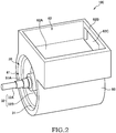
FIG. 2 is a perspective view of the rotating electrical machine system in a state where a semiconductor module is not installed. -
FIG. 3 is a perspective view of the rotating electrical machine system in a state where the semiconductor module is installed. -
FIG. 4 is a part of a vertical cross-sectional view of the rotating electrical machine system. -
FIG. 5 is a part of a vertical cross-sectional view of a rotating electrical machine system according to a second embodiment. -
FIG. 6A is a part of a vertical cross-sectional view of a rotating electrical machine system according to a third embodiment. -
FIG. 6B is a part of a vertical cross-sectional view of the rotating electrical machine system in a state where a semiconductor module is installed. -
FIG. 7 is a part of a vertical cross-sectional view of a rotating electrical machine system according to a fourth embodiment. - Hereinafter, embodiments of the present invention will be described with reference to the drawings and the like.
- The following describes a rotating
electrical machine system 100 according to a first embodiment with reference toFIG. 1. FIG. 1 is a schematic configuration diagram of the rotatingelectrical machine system 100 according to the first embodiment. - The rotating
electrical machine system 100 illustrated inFIG. 1 is a system mounted on, for example, an electric vehicle or a hybrid vehicle. - The rotating
electrical machine system 100 includes abattery 20 as a power supply, anelectrical motor 30 as a driving source that drives wheels, and aninverter 10 electrically coupled to thebattery 20 and themotor 30. The rotatingelectrical machine system 100 is configured to drive themotor 30 using electric power discharged from thebattery 20 and charge thebattery 20 using electric power generated by themotor 30. - The
battery 20, which is a rechargeable and dischargeable secondary battery, is constituted of, for example, a lithium-ion battery. - The
electrical motor 30 is a three-phase AC motor that includes a U-phase terminal, a V-phase terminal, and a W-phase terminal. Themotor 30, which is what is called a rotating electrical machine, functions as the driving source in normal operation, and functions as an electric generator in regeneration. - The
inverter 10 is a power conversion apparatus electrically coupled between thebattery 20 and themotor 30. Theinverter 10 converts DC power of thebattery 20 into AC power to supply the AC power to themotor 30 in normal operation. Theinverter 10 converts AC power from themotor 30 into DC power to supply the DC power to thebattery 20 in regeneration. - The
inverter 10 includes a positive-side power line 11 and a negative-side power line 12. The positive-side power line 11 is coupled to a positive electrode of thebattery 20 via arelay switch 15. The negative-side power line 12 is coupled to a negative electrode of thebattery 20. - Between the positive-
side power line 11 and the negative-side power line 12, acapacitor 14 that smooths voltage between thebattery 20 and theinverter 10 is coupled. Thecapacitor 14 is coupled parallel to thebattery 20. - The
inverter 10 further includes asemiconductor module 13 including six switching elements S1 to S6. Each of the switching elements S1 to S6 of the semiconductor module 13 (a power module) includes an insulated gate bipolar transistor (IGBT) and a rectifier diode that allows current-flow in a direction opposite to the IGBT. - Between the positive-
side power line 11 and the negative-side power line 12, the switching elements S1 and S2 are coupled in series as elements for U-phase, the switching elements S3 and S4 are coupled in series as elements for V-phase, and the switching elements S5 and S6 are coupled in series as elements for W-phase. - The U-phase terminal of the
motor 30 is coupled to a coupling portion where the switching element S1 is coupled to the switching element S2. Furthermore, the V-phase terminal of themotor 30 is coupled to a coupling portion where the switching element S3 is coupled to the switching element S4. The W-phase terminal of themotor 30 is coupled to a coupling portion where the switching element S5 is coupled to the switching element S6. - The above-described six switching elements S1 to S6 are ON/OFF controlled based on a control signal from a
controller 50. For example, thecontroller 50 is constituted of a microcomputer including a central processing unit (CPU), a read-only memory (ROM), a random access memory (RAM), and an input/output interface (I/O interface). - Detection signals of a
current sensor 51 that detects U-phase current, acurrent sensor 52 that detects V-phase current, and acurrent sensor 53 that detects W-phase current are input to thecontroller 50. Other than these signals, detection signals from a voltage sensor that detects voltage of thebattery 20, a rotating speed sensor that detects a rotating speed of themotor 30, and a similar sensor are input to thecontroller 50. - The
controller 50 generates pulse-width modulation signals (PWM signals) based on, for example, the above-described detection signals and a torque command value from a vehicle controller (not illustrated) to perform switching control for the switching elements S1 to S6 of thesemiconductor module 13 by PWM signals. - As illustrated in
FIGs. 2 and3 , in the rotatingelectrical machine system 100, themotor 30 as the rotating electrical machine and theinverter 10 electrically coupled to themotor 30 are integrally disposed via ahousing 60. - As illustrated in
FIG. 2 , thehousing 60 is configured as a case member cast from, for example, aluminum alloy. Thehousing 60 includes amotor chamber 61 as a first chamber that houses themotor 30 and aninverter chamber 62 as a second chamber that houses theinverter 10. - The
motor chamber 61 is formed as a space (cylindrical-shaped space) corresponding to an outer shape of themotor 30. Theinverter chamber 62 is formed as a space (box-shaped space) having abottom portion 62A and asidewall portion 62B. Themotor chamber 61 and theinverter chamber 62 are arranged alongside in a vertical direction. After theinverter 10 is mounted on theinverter chamber 62, an upper opening of theinverter chamber 62 may be obstructed by a lid member (not illustrated). - The
motor 30 includes astator 31 secured to aninner circumference surface 61A of themotor chamber 61 and arotor 32 disposed inside thestator 31 rotatably with respect to thestator 31. - The
rotor 32 includes a rotatingshaft 32A and arotor core 32B mounted on an outer periphery of the rotatingshaft 32A. Therotor core 32B is a cylindrical member constituted of lamination of a plurality of electromagnetic steel plates. Some permanent magnets are disposed inside therotor core 32B. - The
stator 31 is formed into an annular shape so as to surround an outer periphery of therotor 32. Thestator 31 is secured within themotor chamber 61 such that an outer peripheral surface of thestator 31 adheres to theinner circumference surface 61A of themotor chamber 61, by using a method such as a shrink fit. Thestator 31 includes a plurality of teeth portions. A U-phase coil, a V-phase coil, and a W-phase coil are wound around these teeth portions in order. - As illustrated in
FIG. 3 , theinverter chamber 62 of thehousing 60 houses theinverter 10. That is, in theinverter chamber 62, thesemiconductor module 13, thecapacitor 14, thecontroller 50, etc. that constitute theinverter 10 are disposed. - The
semiconductor module 13 including the switching elements S1 to S6 is installed on thebottom portion 62A (bottom surface) of theinverter chamber 62 via a cooler 70. In order to facilitate an assemble of the rotatingelectrical machine system 100, the cooler 70 is secured to thebottom portion 62A of theinverter chamber 62 via securing mechanisms such as bolts, in a state that thesemiconductor module 13 is mounted on the cooler 70. The cooler 70 is a cooling mechanism that cools thesemiconductor module 13 generating heat in switching control. The cooler 70 will be described later in detail with reference toFIG. 4 . - The
semiconductor module 13 is housed in theinverter chamber 62, in a state that thesemiconductor module 13 is placed on the cooler 70. The U-phase, V-phase, and W-phase coupling portions of thesemiconductor module 13 are electrically coupled to the U-phase, V-phase, and W-phase terminals of themotor 30 via U-phase, V-phase, and W-phase busbars phase busbars current sensors - The
sidewall portion 62B of theinverter chamber 62 has a through-hole 62C at a rear end of thehousing 60. Themotor chamber 61 has a rear end formed as an opening end. The U-phase, V-phase, and W-phase busbars motor 30 and thesemiconductor module 13 through the through-hole 62C of thesidewall portion 62B and the opening end of themotor chamber 61. - In the above-described rotating
electrical machine system 100, when themotor 30 is driven, thestator 31 of themotor 30 and thesemiconductor module 13 of theinverter 10 generate heat. Therefore, the rotatingelectrical machine system 100 includes a cooling mechanism that cools thestator 31 of themotor 30 and thesemiconductor module 13 of theinverter 10. - The following describes the cooling mechanism of the rotating
electrical machine system 100 with reference toFIG. 4. FIG. 4 is a part of a vertical cross-sectional view of the rotatingelectrical machine system 100. - As illustrated in
FIG. 4 , the rotatingelectrical machine system 100 according to this embodiment includes acooling path 63 and the cooler 70 as the cooling mechanism. - The cooling
path 63 is formed in thehousing 60 around thestator 31 of themotor 30. The coolingpath 63 is formed to extend in a rotation shaft direction along an outer periphery of thestator 31. The coolingpath 63 is a passage where cooling water (coolant) flows. The cooling water flows through the coolingpath 63 to cool thestator 31 near the coolingpath 63. Thus, the coolingpath 63 is configured as the cooling mechanism for cooling thestator 31 of themotor 30. The plurality of coolingpaths 63 may be disposed around thestarter 31. The coolingpath 63 may be configured as one passage disposed to extend along a peripheral area of thestator 31. - It should be noted that the coolant that flows through the cooling
path 63 is not necessarily cooling water. The coolant may be liquid such as oil or gas such as air. - The cooler 70 is disposed so as to interpose (be sandwiched) between the
bottom portion 62A of theinverter chamber 62 and thesemiconductor module 13. The cooler 70, which is a rectangular plate-shaped member, internally includes a plurality offlow paths 71. Theflow path 71 is formed as a passage configured to extend in the rotation shaft direction of themotor 30. - The plurality of
flow paths 71 are disposed alongside in a direction (a motor-width direction) perpendicular to the rotation shaft direction, and each are disposed in parallel. Theflow path 71 of the cooler 70 is a passages where the cooling water (the coolant) flows. The cooling water flows through theflow path 71 to cool both thesemiconductor module 13 of theinverter 10 and thestator 31 of themotor 30. - Thus, the cooler 70 is configured as the cooling mechanism that ensures cooling not only the
semiconductor module 13 of theinverter 10 positioned above the cooler 70 but also thestator 31 of themotor 30 positioned below the cooler 70. The cooler 70 cools thesemiconductor module 13 and thestator 31, thus volume and a shape of theflow path 71 are designed to be able to cool both members: thesemiconductor module 13 and thestator 31. It should be noted that theflow path 71 may be configured as one passage formed to extend with meandering along a lower surface of thesemiconductor module 13. - In this embodiment, the cooler 70 and the cooling
path 63 are configured such that the cooling water that flows into theflow paths 71 from an inlet portion of the cooler 70 passes through theflow paths 71 to flow into the coolingpath 63 through an outlet portion of the cooler 70. Then, the cooling water that has passed through the coolingpath 63 is cooled by a heat radiation mechanism (not illustrated) to be supplied to the cooler 70 again. Thus, the cooling water that passes through theflow paths 71 of the cooler 70 and the cooling water that passes through the coolingpath 63 are shared. An allowable upper-limit temperature of thesemiconductor module 13 is lower than an allowable upper-limit temperature of thestator 31, thus in a case where the cooling water is shared, it is preferred that the cooling water cooled by the heat radiation mechanism is supplied to the cooler 70 in advance of the coolingpath 63. - It should be noted that the cooling water is shared in this embodiment, however different cooling-water supply sources may be used to separately supply the cooling water to the cooler 70 and the cooling
path 63. - As described above, the cooling mechanism of the rotating
electrical machine system 100 includes the coolingpath 63 and the cooler 70. The cooler 70 cools both thesemiconductor module 13 and thestator 31, thus the coolingpath 63 is disposed in thehousing 60 so as to avoid a part (immediately below the cooler 70) positioned between the cooler 70 and thestator 31. This can avoid overlap of a cooling range of the coolingpath 63 and a cooling range of the cooler 70. - The above-described rotating
electrical machine system 100 of the first embodiment can obtain the following effect. - The rotating
electrical machine system 100 includes the cooler 70 separately from the coolingpath 63 for stator cooling formed in thehousing 60. The cooler 70 is sandwiched between thebottom portion 62A of theinverter chamber 62 and thesemiconductor module 13. The cooler 70 is configured to cool both thesemiconductor module 13 of theinverter 10 and thestator 31 of themotor 30 by the cooling water that passes through an inside of the cooler 70. - The cooler 70 is used for both of the cooling mechanism of the
semiconductor module 13 and the cooling mechanism of thestator 31, thus it is possible to ensure effective cooling of thesemiconductor module 13 and thestator 31 without increasing a size of the rotatingelectrical machine system 100. Consequently, this ensures a high-output-power operation for a long time of themotor 30. - The interposition of the cooler 70 as the plate-shaped member between the
semiconductor module 13 and thestator 31 ensures reinforcement of thebottom portion 62A of theinverter chamber 62 and ensures a housing strength even if thebottom portion 62A is configured thin to some extent. - It should be noted that the cooler 70 is configured to cool the
semiconductor module 13 that constitutes a part of theinverter 10, however the cooler 70 may be configured to cool a semiconductor module of an electric component (such as a converter) coupled to themotor 30 other than theinverter 10. - In the rotating
electrical machine system 100, the coolingpath 63 for stator cooling is disposed in thehousing 60 around thestator 31. In thecooling path 63 and the cooler 70, the cooling water that passes through the coolingpath 63 and the cooling water that passes through the cooler 70 are shared. Thus, sharing of the cooling water also ensures sharing of, for example, the cooling-water supply source and the heat radiation mechanism of the cooling water. It is possible to suppress the increase of the size of the rotatingelectrical machine system 100. - Furthermore, in the rotating
electrical machine system 100, the coolingpath 63 is formed in thehousing 60 so as to avoid the part (immediately below the cooler 70) positioned between the cooler 70 and thestator 31. This can avoid the overlap of the cooling range of the coolingpath 63 and the cooling range of the cooler 70, thus ensuing the effective cooling of thestator 31 and thesemiconductor module 13 while suppressing the increasing of the size of the rotatingelectrical machine system 100. - The following describes a rotating
electrical machine system 100 according to a second embodiment with reference toFIG. 5 . - The rotating
electrical machine system 100 according to the second embodiment is different from the system of the first embodiment, in that a heat-transfer improving member 80 is interposed between the cooler 70 and thebottom portion 62A of theinverter chamber 62. It should be noted that the following embodiments use identical reference numerals to components that have functions identical to those of the first embodiment, and therefore such elements may not be further elaborated here. - As illustrated in
FIG. 5 , in the rotatingelectrical machine system 100 according to the second embodiment, the heat-transfer improving member 80 is disposed (sandwiched) between the cooler 70 and thebottom portion 62A of theinverter chamber 62. - The heat-
transfer improving member 80 is a grease layer formed such that grease is applied between a lower end surface of the cooler 70 and thebottom portion 62A of theinverter chamber 62, or an elastic body having thermal conductivity higher than that of air. The elastic body is disposed between the lower end surface of the cooler 70 and thebottom portion 62A of theinverter chamber 62. - In the rotating
electrical machine system 100 according to the second embodiment, sandwiching the heat-transfer improving member 80 by the cooler 70 and thebottom portion 62A ensures gapless contacts of the cooler 70 and the heat-transfer improving member 80, and thebottom portion 62A and the heat-transfer improving member 80. This ensures reduction of thermal resistance between the respective members to more efficiently cool thestator 31 of themotor 30 by the cooler 70. - It should be noted that in the second embodiment, the heat-
transfer improving member 80 is disposed between the cooler 70 and thebottom portion 62A, however surface processing for reducing surface roughness may be performed on at least one surface of the lower end surface (an installation surface) of the cooler 70 and a bottom portion surface of theinverter chamber 62 instead of the disposition of the heat-transfer improving member 80. - Thus, performing the surface processing ensures the gapless contact of the cooler 70 and the
bottom portion 62A to increase a contacted area of both members. This ensures the reduction of the thermal resistance between the cooler 70 and thebottom portion 62A. Therefore, it is possible to more efficiently cool thestator 31 by the cooler 70 even without the heat-transfer improving member 80. - A surface of the
housing 60 formed by casting tends to harshen. Thus, it is preferred that the surface processing for reducing the surface roughness is performed on the surface of thebottom portion 62A of theinverter chamber 62 formed as a part of thehousing 60, in the case where the surface processing is performed on only one of the cooler 70 and thebottom portion 62A. - Furthermore, in the state where the surface processing is performed on at least one of the cooler 70 and the
bottom portion 62A, the heat-transfer improving member 80 may be disposed between the cooler 70 and thebottom portion 62A. - The following describes a rotating
electrical machine system 100 according to a third embodiment with reference toFIG. 6A and FIG. 6B . - The rotating
electrical machine system 100 according to the third embodiment is different from the systems of the first and the second embodiments in a method of the installation of the cooler 70. - As illustrated in
FIG. 6A , the cooler 70 before being secured to thebottom portion 62A of thehousing 60 is configured as a plate-shaped member curved in the motor-width direction. That is, the lower end surface (the installation surface) of the cooler 70 has a curved shape where a central portion in the motor-width direction projects to thebottom portion 62A of theinverter chamber 62. Since the cooler 70 has a relatively simple plate shape, the cooler 70 can be manufactured using a method such as an extrusion molding. - As illustrated in
FIG. 6B , the curve-shapedcooler 70 is placed on thebottom portion 62A of theinverter chamber 62. After that, the cooler 70 is secured to thebottom portion 62A by a plurality ofbolts 90 as the securing mechanisms. - These
bolts 90 are disposed along an outer edge of the cooler 70. Thebolts 90 are disposed in at least four corners of the cooler 70, which is the rectangular plate shape, however thebolts 90 may be disposed along an outer periphery of the cooler 70 in addition to the four corners. Thebolts 90 are screwed with screw holes of thebottom portion 62A through bolt insertion holes of the cooler 70. This tightly secures the cooler 70 to thebottom portion 62A in a state where the cooler 70 is deformed from the curved shape to a flat-plate shape. - In the rotating
electrical machine system 100 according to the third embodiment, the cooler 70 having the shape curved in the motor-width direction is tightly secured to thebottom portion 62A of theinverter chamber 62 by the plurality ofbolts 90 disposed along the outer edge of this cooler 70. - Thus, tightly securing ensures the tight contact of the cooler 70 and the
bottom portion 62A in a state that maintains a high contact surface pressure, even at the central portion of the cooler 70 not only at the proximity of thebolts 90. This ensures the gapless contact of the cooler 70 and thebottom portion 62A to reduce the thermal resistance between both members. Consequently, it is possible to more efficiently cool thestator 31 of themotor 30 using the cooler 70. - When the
stator 31 is disposed in themotor chamber 61 of thehousing 60 by the shrink fit, the surface of thebottom portion 62A of theinverter chamber 62 curves in the motor-width direction corresponding to an outer peripheral shape of thestator 31. That is, thebottom portion 62A has a curved shape where a central portion in the motor-width direction projects to a side of the cooler 70. - Thus, when the
bottom portion 62A has the curved shape, the cooler 70 may be a flat plate-shaped member, not the curved plate-shaped member. Securing the cooler 70 to thebottom portion 62A, which curves in the motor-width direction, by the plurality ofbolts 90, which are disposed along the outer edge of the cooler 70, also ensures the tight contact of the cooler 70 and thebottom portion 62A in the state that maintains the high contact surface pressure. Consequently, it is possible to more efficiently cool thestator 31 of themotor 30 using the cooler 70. - In the above-described rotating
electrical machine system 100 of the third embodiment, the heat-transfer improving member described in the second embodiment may be disposed between the cooler 70 and thebottom portion 62A, and the surface processing described in the second embodiment may be performed on the cooler 70 and thebottom portion 62A. - The following describes a rotating
electrical machine system 100 according to a fourth embodiment with reference toFIG. 7 . - The rotating
electrical machine system 100 according to the fourth embodiment is different from the systems of the first to the third embodiments in that a part of the cooler 70 is exposed to themotor chamber 61. - As illustrated in
FIG. 7 , adepressed groove 64 where the cooler 70 is engaged, and acommunication hole 65 through which theinverter chamber 62 is communicated with themotor chamber 61 are formed at thebottom portion 62A of theinverter chamber 62. - The cooler 70 is disposed in the
depressed groove 64 of thebottom portion 62A by a method such as a press fit or the shrink fit. In such disposed state, a part of the cooler 70 is exposed to themotor chamber 61 through thecommunication hole 65. The exposed part, which is exposed through thecommunication hole 65, of the cooler 70 is formed as adepressed portion 72 depressed corresponding to the outer peripheral shape of thestator 31 of themotor 30. Thedepressed portion 72 of the cooler 70 is configured so as to contact thestator 31. - In the rotating
electrical machine system 100 according to the fourth embodiment, the depressed portion 72 (the exposed part) of the cooler 70 is exposed to themotor chamber 61 through thecommunication hole 65, and contacts the outer peripheral surface of thestator 31. This ensures direct cooling of thestator 31 of themotor 30 via the cooler 70. Consequently, it is possible to more efficiently cool thestator 31 of themotor 30 using the cooler 70. - It should be noted that an exposed part at the lower end surface of the cooler 70 may be formed as a flat surface. In this case, a part of the outer peripheral surface of the
stator 31 is formed as a flat surface such that the lower end surface, which is exposed through thecommunication hole 65, of the cooler 70 contacts the outer peripheral surface of thestator 31. - In the above-described rotating
electrical machine system 100 of the fourth embodiment, the heat-transfer improving member described in the second embodiment may be disposed between the cooler 70 and thestator 31, and the surface processing described in the second embodiment may be performed on the cooler 70 and thestator 31. - The embodiments of the present invention described above are merely illustration of some application examples of the present invention and not of the nature to limit the technical scope of the present invention to the specific constructions of the above embodiments.
- While the above-described respective embodiments are described as a single embodiment, they may be combined as necessary.
Claims (9)
- A rotating electrical machine system integrally comprising:a rotating electrical machine housed in a first chamber of a housing; anda semiconductor module housed in a second chamber of the housing and electrically coupled to the rotating electrical machine;wherein the rotating electrical machine includes a stator secured to an inner circumference surface of the first chamber and a rotor rotatably disposed with respect to the stator, andthe rotating electrical machine system further comprises a cooler disposed between a bottom portion of the second chamber and the semiconductor module to cool the semiconductor module and the stator by coolant that passes through an inside of the cooler.
- The rotating electrical machine system according to claim 1,
wherein the housing includes a cooling path disposed around the stator to cool the stator by coolant that passes through an inside of the cooling path, and
the coolant that passes through the cooling path and the coolant that passes through the cooler are shared. - The rotating electrical machine system according to claim 2,
wherein the cooling path is formed in the housing so as to avoid a part positioned between the cooler and the stator. - The rotating electrical machine system according to any one of claims 1 to 3,
wherein a heat-transfer improving member is disposed between the bottom portion of the second chamber and the cooler. - The rotating electrical machine system according to any one of claims 1 to 4,
wherein surface processing for reducing surface roughness is performed on at least one of the bottom portion of the second chamber and an end surface of a bottom portion of the cooler. - The rotating electrical machine system according to any one of claims 1 to 5,
wherein one of the bottom portion of the second chamber and an end surface of a bottom portion of the cooler has a curved shape whose central portion projects to another, and
the cooler is tightly secured to the bottom portion by a plurality of securing mechanisms disposed along an outer edge of the cooler. - The rotating electrical machine system according to any one of claims 1 to 3,
wherein a communication hole through which the second chamber is communicated with the first chamber is formed at the bottom portion of the second chamber, and
the cooler is configured to contact the stator through the communication hole. - The rotating electrical machine system according to any one of claims 1 to 7,
wherein the cooler is configured as a plate-shaped member that has a flow path through which coolant flows. - The rotating electrical machine system according to any one of claims 1 to 8,
wherein the semiconductor module is a module that constitutes a part of an inverter.
Applications Claiming Priority (1)
| Application Number | Priority Date | Filing Date | Title |
|---|---|---|---|
| PCT/JP2014/076183 WO2016051535A1 (en) | 2014-09-30 | 2014-09-30 | Rotating electrical machine system |
Publications (3)
| Publication Number | Publication Date |
|---|---|
| EP3203614A1 true EP3203614A1 (en) | 2017-08-09 |
| EP3203614A4 EP3203614A4 (en) | 2017-11-29 |
| EP3203614B1 EP3203614B1 (en) | 2019-08-14 |
Family
ID=55629626
Family Applications (1)
| Application Number | Title | Priority Date | Filing Date |
|---|---|---|---|
| EP14902892.0A Active EP3203614B1 (en) | 2014-09-30 | 2014-09-30 | Rotating electrical machine system |
Country Status (9)
| Country | Link |
|---|---|
| US (1) | US10505427B2 (en) |
| EP (1) | EP3203614B1 (en) |
| JP (1) | JP6304387B2 (en) |
| KR (1) | KR101810377B1 (en) |
| CN (1) | CN107078595B (en) |
| BR (1) | BR112017006119B1 (en) |
| MX (1) | MX364631B (en) |
| RU (1) | RU2637805C1 (en) |
| WO (1) | WO2016051535A1 (en) |
Cited By (4)
| Publication number | Priority date | Publication date | Assignee | Title |
|---|---|---|---|---|
| EP3300222A4 (en) * | 2015-05-20 | 2018-05-30 | Nissan Motor Co., Ltd. | In-vehicle drive device |
| WO2019063306A1 (en) * | 2017-09-29 | 2019-04-04 | Valeo Equipements Electriques Moteur | Liquid cooling circuit for a rotary electric machine |
| WO2020127379A1 (en) * | 2018-12-21 | 2020-06-25 | Vitesco Technologies Germany Gmbh | Electric motor |
| EP4530106A1 (en) * | 2023-08-25 | 2025-04-02 | Aisin Corporation | Vehicle driving device |
Families Citing this family (29)
| Publication number | Priority date | Publication date | Assignee | Title |
|---|---|---|---|---|
| WO2017190697A1 (en) * | 2016-05-05 | 2017-11-09 | 东风农业装备(襄阳)有限公司 | Electric rice seedling planter and application thereof |
| EP3488514B8 (en) * | 2016-07-20 | 2021-10-20 | LG Magna e-Powertrain Co., Ltd. | Case for electric motor |
| CN106533035A (en) * | 2016-12-30 | 2017-03-22 | 合普动力股份有限公司 | Integral motor controller for electric vehicle |
| JP6885126B2 (en) * | 2017-03-22 | 2021-06-09 | 富士電機株式会社 | Inverter device |
| FI130033B (en) * | 2017-05-24 | 2022-12-30 | Aurora Powertrains Oy | A snowmobile with an electric motor, and a manufacturing method for a snowmobile with an electric motor |
| DE102017220550A1 (en) * | 2017-11-17 | 2019-05-23 | Zf Friedrichshafen Ag | Cooling system for a drive system and vehicle drive system |
| WO2019117119A1 (en) * | 2017-12-14 | 2019-06-20 | 日本電産株式会社 | Inverter, inverter in case, electric motor having built-in inverter, and composite device having built-in inverter |
| DE102018113099A1 (en) * | 2018-06-01 | 2019-12-05 | Thyssenkrupp Ag | Housing assembly for an electric drive or an electric drive unit, engine and vehicle |
| JP6977682B2 (en) * | 2018-07-25 | 2021-12-08 | 株式会社デンソー | Rotating electric machine unit |
| CN109451696B (en) * | 2018-09-26 | 2020-10-27 | 天长市天毅电子科技有限公司 | Water-cooled electric vehicle charger |
| JP2020054185A (en) * | 2018-09-28 | 2020-04-02 | 日本電産トーソク株式会社 | Motor drive unit |
| WO2020166150A1 (en) * | 2019-02-12 | 2020-08-20 | アイシン・エィ・ダブリュ株式会社 | Inverter unit |
| US11031846B2 (en) * | 2019-03-08 | 2021-06-08 | Abb Schweiz Ag | Co-packaged electric motor and motor drive |
| KR102171845B1 (en) * | 2019-06-03 | 2020-10-29 | 뉴모텍(주) | Driving Motor with Inverter Housing for Electric Vehicle |
| US10780849B1 (en) * | 2019-08-07 | 2020-09-22 | GM Global Technology Operations LLC | Electric drive units with integrated power electronics for vehicle powertrains |
| EP4027496A4 (en) * | 2019-09-03 | 2024-02-14 | Nidec Corporation | Motor |
| US12113404B2 (en) * | 2019-09-30 | 2024-10-08 | Nidec Corporation | Motor unit |
| JP6824370B1 (en) * | 2019-12-02 | 2021-02-03 | 三菱電機株式会社 | Rotating machine |
| FR3105892B1 (en) * | 2019-12-31 | 2023-07-14 | Thales Sa | COOLING DEVICE AND MOTOR-VARIATOR |
| DE102020202781A1 (en) * | 2020-03-04 | 2021-09-09 | Siemens Aktiengesellschaft | 8Electric motor with can |
| US11230288B1 (en) | 2020-09-28 | 2022-01-25 | GM Global Technology Operations LLC | Optimized regenerative braking for hybrid electric vehicle (HEV) powertrain configurations |
| EP4027494B1 (en) * | 2021-01-08 | 2023-11-08 | Taiga Motors Inc. | Drive unit for electric vehicle |
| CN116964913A (en) | 2021-03-09 | 2023-10-27 | 加特可株式会社 | part |
| CN114337063A (en) * | 2021-12-31 | 2022-04-12 | 中国第一汽车股份有限公司 | Electric drive system and automobile |
| US11942825B2 (en) * | 2022-01-12 | 2024-03-26 | Dana Automotive Systems Group, Llc | Cooling system for an electric machine |
| JP2023110968A (en) * | 2022-01-31 | 2023-08-10 | 三菱電機株式会社 | Rotating electric machine unit |
| EP4526983A4 (en) * | 2022-05-16 | 2026-05-06 | Hydro Gear Lp | LIQUID-COOLED ELECTRIC DRIVE ARRANGEMENT |
| CN117294083A (en) * | 2022-06-20 | 2023-12-26 | 法雷奥西门子新能源汽车德国有限责任公司 | Electric drive assembly, vehicle and method for assembling an electric drive assembly |
| US20240429790A1 (en) * | 2023-06-22 | 2024-12-26 | Solaredge Technologies Ltd. | Motor Integrated Inverter |
Family Cites Families (29)
| Publication number | Priority date | Publication date | Assignee | Title |
|---|---|---|---|---|
| DE4311518A1 (en) | 1993-04-07 | 1994-10-13 | Siemens Ag | Drive device for a vehicle |
| US5491370A (en) * | 1994-01-28 | 1996-02-13 | General Motors Corporation | Integrated AC machine |
| SE513419C2 (en) * | 1996-12-20 | 2000-09-11 | Abb Ab | Device comprising an electric machine with control equipment having cooling |
| DE19817333C5 (en) | 1998-04-18 | 2007-04-26 | Conti Temic Microelectronic Gmbh | Electric drive unit consisting of electric motor and electronic module |
| JP3877898B2 (en) * | 1999-02-23 | 2007-02-07 | 三菱電機株式会社 | AC generator for vehicles |
| US6339271B1 (en) * | 1999-12-21 | 2002-01-15 | Bombardier Motor Corporation Of America | Molded flywheel magnet cage |
| US6992409B2 (en) * | 2002-03-15 | 2006-01-31 | Denso Corporation | Liquid-cooled rotary electric machine integrated with an inverter |
| DE60331611D1 (en) * | 2002-09-13 | 2010-04-15 | Aisin Aw Co | drive unit |
| JP4327618B2 (en) | 2004-02-05 | 2009-09-09 | トヨタ自動車株式会社 | Inverter-integrated rotating electrical machine and vehicle equipped with the rotating electrical machine |
| KR100566509B1 (en) * | 2004-04-07 | 2006-04-03 | 주식회사 한국성산 | Stator iron core for generator and motor |
| US20070013241A1 (en) * | 2005-07-13 | 2007-01-18 | Schiferl Rich F | Lamination stack cooling path |
| JP4675311B2 (en) | 2006-11-16 | 2011-04-20 | トヨタ自動車株式会社 | Inverter and condenser cooling structure accommodated integrally with motor in motor housing, motor unit and housing having the cooling structure |
| JP4861840B2 (en) | 2007-01-26 | 2012-01-25 | アイシン・エィ・ダブリュ株式会社 | Heating element cooling structure and driving device |
| DE102007034913B4 (en) * | 2007-07-24 | 2014-08-28 | Sew-Eurodrive Gmbh & Co Kg | Fan cover for one inverter motor, inverter motor and series of inverter motors |
| JP4874890B2 (en) * | 2007-08-10 | 2012-02-15 | トヨタ自動車株式会社 | Drive device |
| DE102008027002A1 (en) * | 2008-06-05 | 2009-12-24 | Gildemeister Drehmaschinen Gmbh | electric motor |
| DE102010002068A1 (en) * | 2010-02-18 | 2011-08-18 | Siemens Aktiengesellschaft, 80333 | motor unit |
| DE102010008584A1 (en) * | 2010-02-19 | 2011-08-25 | Magna Powertrain Ag & Co Kg | Electric drive unit |
| EP2537235B1 (en) * | 2010-02-19 | 2015-04-22 | Magna Powertrain AG & Co. KG | Electric drive unit |
| JP5492599B2 (en) * | 2010-02-26 | 2014-05-14 | 日立オートモティブシステムズ株式会社 | Rotating electrical machine system |
| JP5472443B2 (en) * | 2010-12-24 | 2014-04-16 | トヨタ自動車株式会社 | Cooler |
| CN103814515B (en) * | 2011-09-20 | 2016-05-04 | 三菱电机株式会社 | Mechatronic components |
| JP5594275B2 (en) * | 2011-11-10 | 2014-09-24 | 株式会社安川電機 | Rotating electric machine |
| WO2013069322A1 (en) * | 2011-11-11 | 2013-05-16 | 株式会社安川電機 | Rotating electrical machine and vehicle |
| JP5859031B2 (en) * | 2012-02-07 | 2016-02-10 | 三菱電機株式会社 | Mechanical and electrical integrated module |
| JP6134127B2 (en) | 2012-11-21 | 2017-05-24 | 三菱重工業株式会社 | Equipment with heat sink |
| US9246370B2 (en) * | 2013-01-17 | 2016-01-26 | Remy Technologies, Llc | Electric motor stator housing interference gap reducing method and apparatus |
| DE102013201758A1 (en) | 2013-02-04 | 2014-08-07 | Schaeffler Technologies Gmbh & Co. Kg | Electric machine with a cooling device and method for its production |
| CN103683685B (en) * | 2013-10-22 | 2016-09-14 | 宁波腾隆户外用品有限公司 | Integrated servo motor |
-
2014
- 2014-09-30 JP JP2016551407A patent/JP6304387B2/en active Active
- 2014-09-30 KR KR1020177008283A patent/KR101810377B1/en not_active Expired - Fee Related
- 2014-09-30 BR BR112017006119-8A patent/BR112017006119B1/en not_active IP Right Cessation
- 2014-09-30 EP EP14902892.0A patent/EP3203614B1/en active Active
- 2014-09-30 WO PCT/JP2014/076183 patent/WO2016051535A1/en not_active Ceased
- 2014-09-30 CN CN201480082323.8A patent/CN107078595B/en active Active
- 2014-09-30 RU RU2017110620A patent/RU2637805C1/en active
- 2014-09-30 MX MX2017004030A patent/MX364631B/en active IP Right Grant
- 2014-09-30 US US15/514,184 patent/US10505427B2/en active Active
Cited By (6)
| Publication number | Priority date | Publication date | Assignee | Title |
|---|---|---|---|---|
| EP3300222A4 (en) * | 2015-05-20 | 2018-05-30 | Nissan Motor Co., Ltd. | In-vehicle drive device |
| US10680488B2 (en) | 2015-05-20 | 2020-06-09 | Nissan Motor Co., Ltd. | In-vehicle drive device with cooling channels |
| WO2019063306A1 (en) * | 2017-09-29 | 2019-04-04 | Valeo Equipements Electriques Moteur | Liquid cooling circuit for a rotary electric machine |
| FR3071978A1 (en) * | 2017-09-29 | 2019-04-05 | Valeo Equipements Electriques Moteur | COOLING CIRCUIT WITH LIQUID FOR ROTATING ELECTRIC MACHINE |
| WO2020127379A1 (en) * | 2018-12-21 | 2020-06-25 | Vitesco Technologies Germany Gmbh | Electric motor |
| EP4530106A1 (en) * | 2023-08-25 | 2025-04-02 | Aisin Corporation | Vehicle driving device |
Also Published As
| Publication number | Publication date |
|---|---|
| MX364631B (en) | 2019-05-03 |
| KR101810377B1 (en) | 2017-12-20 |
| EP3203614A4 (en) | 2017-11-29 |
| CN107078595A (en) | 2017-08-18 |
| WO2016051535A1 (en) | 2016-04-07 |
| BR112017006119B1 (en) | 2021-11-23 |
| BR112017006119A2 (en) | 2017-12-19 |
| CN107078595B (en) | 2019-11-05 |
| JPWO2016051535A1 (en) | 2017-07-27 |
| KR20170046742A (en) | 2017-05-02 |
| EP3203614B1 (en) | 2019-08-14 |
| RU2637805C1 (en) | 2017-12-07 |
| MX2017004030A (en) | 2017-05-30 |
| US10505427B2 (en) | 2019-12-10 |
| JP6304387B2 (en) | 2018-04-04 |
| US20170294821A1 (en) | 2017-10-12 |
Similar Documents
| Publication | Publication Date | Title |
|---|---|---|
| US10505427B2 (en) | Rotating electrical machine system | |
| US9438088B2 (en) | Rotating electrical machine unit with a power inverter having a ring-shaped casing | |
| US9159506B2 (en) | Capacitor module and power conversion device | |
| US11509196B2 (en) | Motor vehicle and power converter device for a motor vehicle | |
| US9881019B2 (en) | Rotating electric machine system | |
| US9596782B2 (en) | Power converter with cooling board | |
| JP6838853B2 (en) | Rotating electrical system | |
| JP4106061B2 (en) | Power unit device and power conversion device | |
| JP5815063B2 (en) | Power converter | |
| JP2017200315A (en) | Semiconductor device | |
| JP2010245910A (en) | Power conversion device and in-vehicle electric system using the same | |
| JP2013005067A (en) | Power conversion apparatus | |
| JP2010011671A (en) | Power convertor | |
| CN114430239B (en) | Power module, inverter with power module, and electric drive with inverter | |
| WO2020195788A1 (en) | Electromechanical unit | |
| JP2013188105A (en) | Electric power conversion device | |
| JP5644643B2 (en) | Load drive device | |
| JP2014150215A (en) | Cooling device and motor control device including the same | |
| KR20130131354A (en) | Cooling system for an electric machine system including an alternating current (ac) electric machine having an integrated switch assembly | |
| KR20140056135A (en) | Electric machine system including an alternating electric current (ac) electric machine having a switch module | |
| JP2015027259A (en) | Power converter | |
| KR20130131357A (en) | Inverter for an electric machine |
Legal Events
| Date | Code | Title | Description |
|---|---|---|---|
| STAA | Information on the status of an ep patent application or granted ep patent |
Free format text: STATUS: THE INTERNATIONAL PUBLICATION HAS BEEN MADE |
|
| PUAI | Public reference made under article 153(3) epc to a published international application that has entered the european phase |
Free format text: ORIGINAL CODE: 0009012 |
|
| STAA | Information on the status of an ep patent application or granted ep patent |
Free format text: STATUS: REQUEST FOR EXAMINATION WAS MADE |
|
| 17P | Request for examination filed |
Effective date: 20170330 |
|
| AK | Designated contracting states |
Kind code of ref document: A1 Designated state(s): AL AT BE BG CH CY CZ DE DK EE ES FI FR GB GR HR HU IE IS IT LI LT LU LV MC MK MT NL NO PL PT RO RS SE SI SK SM TR |
|
| AX | Request for extension of the european patent |
Extension state: BA ME |
|
| REG | Reference to a national code |
Ref country code: DE Ref legal event code: R079 Ref document number: 602014051981 Country of ref document: DE Free format text: PREVIOUS MAIN CLASS: H02K0005200000 Ipc: H02K0011330000 |
|
| A4 | Supplementary search report drawn up and despatched |
Effective date: 20171102 |
|
| RIC1 | Information provided on ipc code assigned before grant |
Ipc: H02K 11/33 20160101AFI20171024BHEP Ipc: H02K 9/19 20060101ALI20171024BHEP Ipc: H02K 5/20 20060101ALI20171024BHEP Ipc: H02K 9/16 20060101ALI20171024BHEP Ipc: H02K 9/22 20060101ALI20171024BHEP |
|
| DAX | Request for extension of the european patent (deleted) | ||
| STAA | Information on the status of an ep patent application or granted ep patent |
Free format text: STATUS: EXAMINATION IS IN PROGRESS |
|
| 17Q | First examination report despatched |
Effective date: 20180518 |
|
| GRAP | Despatch of communication of intention to grant a patent |
Free format text: ORIGINAL CODE: EPIDOSNIGR1 |
|
| STAA | Information on the status of an ep patent application or granted ep patent |
Free format text: STATUS: GRANT OF PATENT IS INTENDED |
|
| INTG | Intention to grant announced |
Effective date: 20190429 |
|
| GRAS | Grant fee paid |
Free format text: ORIGINAL CODE: EPIDOSNIGR3 |
|
| GRAA | (expected) grant |
Free format text: ORIGINAL CODE: 0009210 |
|
| STAA | Information on the status of an ep patent application or granted ep patent |
Free format text: STATUS: THE PATENT HAS BEEN GRANTED |
|
| RIN1 | Information on inventor provided before grant (corrected) |
Inventor name: UMINO, TOMOHIRO Inventor name: KUBOTA, YASUYUKI Inventor name: SHIMIZU, HIROFUMI |
|
| AK | Designated contracting states |
Kind code of ref document: B1 Designated state(s): AL AT BE BG CH CY CZ DE DK EE ES FI FR GB GR HR HU IE IS IT LI LT LU LV MC MK MT NL NO PL PT RO RS SE SI SK SM TR |
|
| REG | Reference to a national code |
Ref country code: GB Ref legal event code: FG4D |
|
| REG | Reference to a national code |
Ref country code: CH Ref legal event code: EP Ref country code: AT Ref legal event code: REF Ref document number: 1168179 Country of ref document: AT Kind code of ref document: T Effective date: 20190815 |
|
| REG | Reference to a national code |
Ref country code: IE Ref legal event code: FG4D |
|
| REG | Reference to a national code |
Ref country code: DE Ref legal event code: R096 Ref document number: 602014051981 Country of ref document: DE |
|
| REG | Reference to a national code |
Ref country code: NL Ref legal event code: MP Effective date: 20190814 |
|
| REG | Reference to a national code |
Ref country code: LT Ref legal event code: MG4D |
|
| PG25 | Lapsed in a contracting state [announced via postgrant information from national office to epo] |
Ref country code: FI Free format text: LAPSE BECAUSE OF FAILURE TO SUBMIT A TRANSLATION OF THE DESCRIPTION OR TO PAY THE FEE WITHIN THE PRESCRIBED TIME-LIMIT Effective date: 20190814 Ref country code: HR Free format text: LAPSE BECAUSE OF FAILURE TO SUBMIT A TRANSLATION OF THE DESCRIPTION OR TO PAY THE FEE WITHIN THE PRESCRIBED TIME-LIMIT Effective date: 20190814 Ref country code: BG Free format text: LAPSE BECAUSE OF FAILURE TO SUBMIT A TRANSLATION OF THE DESCRIPTION OR TO PAY THE FEE WITHIN THE PRESCRIBED TIME-LIMIT Effective date: 20191114 Ref country code: LT Free format text: LAPSE BECAUSE OF FAILURE TO SUBMIT A TRANSLATION OF THE DESCRIPTION OR TO PAY THE FEE WITHIN THE PRESCRIBED TIME-LIMIT Effective date: 20190814 Ref country code: NL Free format text: LAPSE BECAUSE OF FAILURE TO SUBMIT A TRANSLATION OF THE DESCRIPTION OR TO PAY THE FEE WITHIN THE PRESCRIBED TIME-LIMIT Effective date: 20190814 Ref country code: NO Free format text: LAPSE BECAUSE OF FAILURE TO SUBMIT A TRANSLATION OF THE DESCRIPTION OR TO PAY THE FEE WITHIN THE PRESCRIBED TIME-LIMIT Effective date: 20191114 Ref country code: PT Free format text: LAPSE BECAUSE OF FAILURE TO SUBMIT A TRANSLATION OF THE DESCRIPTION OR TO PAY THE FEE WITHIN THE PRESCRIBED TIME-LIMIT Effective date: 20191216 Ref country code: SE Free format text: LAPSE BECAUSE OF FAILURE TO SUBMIT A TRANSLATION OF THE DESCRIPTION OR TO PAY THE FEE WITHIN THE PRESCRIBED TIME-LIMIT Effective date: 20190814 |
|
| REG | Reference to a national code |
Ref country code: AT Ref legal event code: MK05 Ref document number: 1168179 Country of ref document: AT Kind code of ref document: T Effective date: 20190814 |
|
| PG25 | Lapsed in a contracting state [announced via postgrant information from national office to epo] |
Ref country code: RS Free format text: LAPSE BECAUSE OF FAILURE TO SUBMIT A TRANSLATION OF THE DESCRIPTION OR TO PAY THE FEE WITHIN THE PRESCRIBED TIME-LIMIT Effective date: 20190814 Ref country code: IS Free format text: LAPSE BECAUSE OF FAILURE TO SUBMIT A TRANSLATION OF THE DESCRIPTION OR TO PAY THE FEE WITHIN THE PRESCRIBED TIME-LIMIT Effective date: 20191214 Ref country code: AL Free format text: LAPSE BECAUSE OF FAILURE TO SUBMIT A TRANSLATION OF THE DESCRIPTION OR TO PAY THE FEE WITHIN THE PRESCRIBED TIME-LIMIT Effective date: 20190814 Ref country code: GR Free format text: LAPSE BECAUSE OF FAILURE TO SUBMIT A TRANSLATION OF THE DESCRIPTION OR TO PAY THE FEE WITHIN THE PRESCRIBED TIME-LIMIT Effective date: 20191115 Ref country code: ES Free format text: LAPSE BECAUSE OF FAILURE TO SUBMIT A TRANSLATION OF THE DESCRIPTION OR TO PAY THE FEE WITHIN THE PRESCRIBED TIME-LIMIT Effective date: 20190814 Ref country code: LV Free format text: LAPSE BECAUSE OF FAILURE TO SUBMIT A TRANSLATION OF THE DESCRIPTION OR TO PAY THE FEE WITHIN THE PRESCRIBED TIME-LIMIT Effective date: 20190814 |
|
| PG25 | Lapsed in a contracting state [announced via postgrant information from national office to epo] |
Ref country code: TR Free format text: LAPSE BECAUSE OF FAILURE TO SUBMIT A TRANSLATION OF THE DESCRIPTION OR TO PAY THE FEE WITHIN THE PRESCRIBED TIME-LIMIT Effective date: 20190814 |
|
| PG25 | Lapsed in a contracting state [announced via postgrant information from national office to epo] |
Ref country code: EE Free format text: LAPSE BECAUSE OF FAILURE TO SUBMIT A TRANSLATION OF THE DESCRIPTION OR TO PAY THE FEE WITHIN THE PRESCRIBED TIME-LIMIT Effective date: 20190814 Ref country code: DK Free format text: LAPSE BECAUSE OF FAILURE TO SUBMIT A TRANSLATION OF THE DESCRIPTION OR TO PAY THE FEE WITHIN THE PRESCRIBED TIME-LIMIT Effective date: 20190814 Ref country code: AT Free format text: LAPSE BECAUSE OF FAILURE TO SUBMIT A TRANSLATION OF THE DESCRIPTION OR TO PAY THE FEE WITHIN THE PRESCRIBED TIME-LIMIT Effective date: 20190814 Ref country code: IT Free format text: LAPSE BECAUSE OF FAILURE TO SUBMIT A TRANSLATION OF THE DESCRIPTION OR TO PAY THE FEE WITHIN THE PRESCRIBED TIME-LIMIT Effective date: 20190814 Ref country code: RO Free format text: LAPSE BECAUSE OF FAILURE TO SUBMIT A TRANSLATION OF THE DESCRIPTION OR TO PAY THE FEE WITHIN THE PRESCRIBED TIME-LIMIT Effective date: 20190814 Ref country code: PL Free format text: LAPSE BECAUSE OF FAILURE TO SUBMIT A TRANSLATION OF THE DESCRIPTION OR TO PAY THE FEE WITHIN THE PRESCRIBED TIME-LIMIT Effective date: 20190814 |
|
| PG25 | Lapsed in a contracting state [announced via postgrant information from national office to epo] |
Ref country code: SK Free format text: LAPSE BECAUSE OF FAILURE TO SUBMIT A TRANSLATION OF THE DESCRIPTION OR TO PAY THE FEE WITHIN THE PRESCRIBED TIME-LIMIT Effective date: 20190814 Ref country code: MC Free format text: LAPSE BECAUSE OF FAILURE TO SUBMIT A TRANSLATION OF THE DESCRIPTION OR TO PAY THE FEE WITHIN THE PRESCRIBED TIME-LIMIT Effective date: 20190814 Ref country code: IS Free format text: LAPSE BECAUSE OF FAILURE TO SUBMIT A TRANSLATION OF THE DESCRIPTION OR TO PAY THE FEE WITHIN THE PRESCRIBED TIME-LIMIT Effective date: 20200224 Ref country code: CZ Free format text: LAPSE BECAUSE OF FAILURE TO SUBMIT A TRANSLATION OF THE DESCRIPTION OR TO PAY THE FEE WITHIN THE PRESCRIBED TIME-LIMIT Effective date: 20190814 Ref country code: SM Free format text: LAPSE BECAUSE OF FAILURE TO SUBMIT A TRANSLATION OF THE DESCRIPTION OR TO PAY THE FEE WITHIN THE PRESCRIBED TIME-LIMIT Effective date: 20190814 |
|
| REG | Reference to a national code |
Ref country code: CH Ref legal event code: PL |
|
| REG | Reference to a national code |
Ref country code: DE Ref legal event code: R097 Ref document number: 602014051981 Country of ref document: DE |
|
| PLBE | No opposition filed within time limit |
Free format text: ORIGINAL CODE: 0009261 |
|
| STAA | Information on the status of an ep patent application or granted ep patent |
Free format text: STATUS: NO OPPOSITION FILED WITHIN TIME LIMIT |
|
| PG2D | Information on lapse in contracting state deleted |
Ref country code: IS |
|
| PG25 | Lapsed in a contracting state [announced via postgrant information from national office to epo] |
Ref country code: CH Free format text: LAPSE BECAUSE OF NON-PAYMENT OF DUE FEES Effective date: 20190930 Ref country code: IE Free format text: LAPSE BECAUSE OF NON-PAYMENT OF DUE FEES Effective date: 20190930 Ref country code: LI Free format text: LAPSE BECAUSE OF NON-PAYMENT OF DUE FEES Effective date: 20190930 Ref country code: LU Free format text: LAPSE BECAUSE OF NON-PAYMENT OF DUE FEES Effective date: 20190930 |
|
| 26N | No opposition filed |
Effective date: 20200603 |
|
| REG | Reference to a national code |
Ref country code: BE Ref legal event code: MM Effective date: 20190930 |
|
| PG25 | Lapsed in a contracting state [announced via postgrant information from national office to epo] |
Ref country code: SI Free format text: LAPSE BECAUSE OF FAILURE TO SUBMIT A TRANSLATION OF THE DESCRIPTION OR TO PAY THE FEE WITHIN THE PRESCRIBED TIME-LIMIT Effective date: 20190814 Ref country code: BE Free format text: LAPSE BECAUSE OF NON-PAYMENT OF DUE FEES Effective date: 20190930 |
|
| PG25 | Lapsed in a contracting state [announced via postgrant information from national office to epo] |
Ref country code: CY Free format text: LAPSE BECAUSE OF FAILURE TO SUBMIT A TRANSLATION OF THE DESCRIPTION OR TO PAY THE FEE WITHIN THE PRESCRIBED TIME-LIMIT Effective date: 20190814 |
|
| PG25 | Lapsed in a contracting state [announced via postgrant information from national office to epo] |
Ref country code: MT Free format text: LAPSE BECAUSE OF FAILURE TO SUBMIT A TRANSLATION OF THE DESCRIPTION OR TO PAY THE FEE WITHIN THE PRESCRIBED TIME-LIMIT Effective date: 20190814 Ref country code: HU Free format text: LAPSE BECAUSE OF FAILURE TO SUBMIT A TRANSLATION OF THE DESCRIPTION OR TO PAY THE FEE WITHIN THE PRESCRIBED TIME-LIMIT; INVALID AB INITIO Effective date: 20140930 |
|
| PG25 | Lapsed in a contracting state [announced via postgrant information from national office to epo] |
Ref country code: MK Free format text: LAPSE BECAUSE OF FAILURE TO SUBMIT A TRANSLATION OF THE DESCRIPTION OR TO PAY THE FEE WITHIN THE PRESCRIBED TIME-LIMIT Effective date: 20190814 |
|
| PGFP | Annual fee paid to national office [announced via postgrant information from national office to epo] |
Ref country code: DE Payment date: 20250820 Year of fee payment: 12 |
|
| PGFP | Annual fee paid to national office [announced via postgrant information from national office to epo] |
Ref country code: GB Payment date: 20250822 Year of fee payment: 12 |
|
| PGFP | Annual fee paid to national office [announced via postgrant information from national office to epo] |
Ref country code: FR Payment date: 20250821 Year of fee payment: 12 |