EP3203172A1 - Heat storage unit and heat storage system - Google Patents
Heat storage unit and heat storage system Download PDFInfo
- Publication number
- EP3203172A1 EP3203172A1 EP15846449.5A EP15846449A EP3203172A1 EP 3203172 A1 EP3203172 A1 EP 3203172A1 EP 15846449 A EP15846449 A EP 15846449A EP 3203172 A1 EP3203172 A1 EP 3203172A1
- Authority
- EP
- European Patent Office
- Prior art keywords
- heat storage
- heat
- space
- storage unit
- unit
- Prior art date
- Legal status (The legal status is an assumption and is not a legal conclusion. Google has not performed a legal analysis and makes no representation as to the accuracy of the status listed.)
- Granted
Links
Images




Classifications
-
- F—MECHANICAL ENGINEERING; LIGHTING; HEATING; WEAPONS; BLASTING
- F28—HEAT EXCHANGE IN GENERAL
- F28D—HEAT-EXCHANGE APPARATUS, NOT PROVIDED FOR IN ANOTHER SUBCLASS, IN WHICH THE HEAT-EXCHANGE MEDIA DO NOT COME INTO DIRECT CONTACT
- F28D20/00—Heat storage plants or apparatus in general; Regenerative heat-exchange apparatus not covered by groups F28D17/00 or F28D19/00
- F28D20/02—Heat storage plants or apparatus in general; Regenerative heat-exchange apparatus not covered by groups F28D17/00 or F28D19/00 using latent heat
-
- C—CHEMISTRY; METALLURGY
- C09—DYES; PAINTS; POLISHES; NATURAL RESINS; ADHESIVES; COMPOSITIONS NOT OTHERWISE PROVIDED FOR; APPLICATIONS OF MATERIALS NOT OTHERWISE PROVIDED FOR
- C09K—MATERIALS FOR MISCELLANEOUS APPLICATIONS, NOT PROVIDED FOR ELSEWHERE
- C09K5/00—Heat-transfer, heat-exchange or heat-storage materials, e.g. refrigerants; Materials for the production of heat or cold by chemical reactions other than by combustion
- C09K5/08—Materials not undergoing a change of physical state when used
- C09K5/14—Solid materials, e.g. powdery or granular
-
- C—CHEMISTRY; METALLURGY
- C09—DYES; PAINTS; POLISHES; NATURAL RESINS; ADHESIVES; COMPOSITIONS NOT OTHERWISE PROVIDED FOR; APPLICATIONS OF MATERIALS NOT OTHERWISE PROVIDED FOR
- C09K—MATERIALS FOR MISCELLANEOUS APPLICATIONS, NOT PROVIDED FOR ELSEWHERE
- C09K5/00—Heat-transfer, heat-exchange or heat-storage materials, e.g. refrigerants; Materials for the production of heat or cold by chemical reactions other than by combustion
- C09K5/02—Materials undergoing a change of physical state when used
-
- F—MECHANICAL ENGINEERING; LIGHTING; HEATING; WEAPONS; BLASTING
- F28—HEAT EXCHANGE IN GENERAL
- F28D—HEAT-EXCHANGE APPARATUS, NOT PROVIDED FOR IN ANOTHER SUBCLASS, IN WHICH THE HEAT-EXCHANGE MEDIA DO NOT COME INTO DIRECT CONTACT
- F28D20/00—Heat storage plants or apparatus in general; Regenerative heat-exchange apparatus not covered by groups F28D17/00 or F28D19/00
- F28D20/0056—Heat storage plants or apparatus in general; Regenerative heat-exchange apparatus not covered by groups F28D17/00 or F28D19/00 using solid heat storage material
-
- F—MECHANICAL ENGINEERING; LIGHTING; HEATING; WEAPONS; BLASTING
- F28—HEAT EXCHANGE IN GENERAL
- F28D—HEAT-EXCHANGE APPARATUS, NOT PROVIDED FOR IN ANOTHER SUBCLASS, IN WHICH THE HEAT-EXCHANGE MEDIA DO NOT COME INTO DIRECT CONTACT
- F28D21/00—Heat-exchange apparatus not covered by any of the groups F28D1/00 - F28D20/00
- F28D21/0001—Recuperative heat exchangers
- F28D21/0003—Recuperative heat exchangers the heat being recuperated from exhaust gases
-
- F—MECHANICAL ENGINEERING; LIGHTING; HEATING; WEAPONS; BLASTING
- F28—HEAT EXCHANGE IN GENERAL
- F28F—DETAILS OF HEAT-EXCHANGE AND HEAT-TRANSFER APPARATUS, OF GENERAL APPLICATION
- F28F5/00—Elements specially adapted for movement
- F28F5/02—Rotary drums or rollers
-
- Y—GENERAL TAGGING OF NEW TECHNOLOGICAL DEVELOPMENTS; GENERAL TAGGING OF CROSS-SECTIONAL TECHNOLOGIES SPANNING OVER SEVERAL SECTIONS OF THE IPC; TECHNICAL SUBJECTS COVERED BY FORMER USPC CROSS-REFERENCE ART COLLECTIONS [XRACs] AND DIGESTS
- Y02—TECHNOLOGIES OR APPLICATIONS FOR MITIGATION OR ADAPTATION AGAINST CLIMATE CHANGE
- Y02E—REDUCTION OF GREENHOUSE GAS [GHG] EMISSIONS, RELATED TO ENERGY GENERATION, TRANSMISSION OR DISTRIBUTION
- Y02E60/00—Enabling technologies; Technologies with a potential or indirect contribution to GHG emissions mitigation
- Y02E60/14—Thermal energy storage
Definitions
- the present disclosure relates to a heat storage unit and a heat storage system.
- Patent Document 1 a heat storage material made of material that undergoes an electron phase transition has been known (refer to Patent Document 1).
- the heat storage material utilizes an enthalpy change associated with the electron phase transition for heat storage.
- the heat storage material described in Patent Document 1 has insufficient thermal conductivity. Therefore, heat of a heat transport medium cannot be efficiently stored in the heat storage material in some cases.
- Patent Document 1 JP 2010-163510 A
- An object of the present disclosure is to provide a heat storage unit and a heat storage system capable of efficiently storing heat of a heat transport medium.
- a heat storage unit includes a heat storage portion having a first material including a strongly correlated electron system material, and a heat conduction portion including a second material that is higher in thermal conductivity than the first material and the heat conduction portion is in contact with the heat storage portion.
- the heat storage unit according to the present disclosure can transfer the heat of the heat transport medium to the heat storage portion through the heat conduction portion having a second material having a thermal conductivity higher than that of the first material. Therefore, the heat storage unit according to the present disclosure can efficiently store the heat of the heat transport medium.
- a heat storage unit includes a heat storage portion having a first material with a strongly correlated electron system material.
- the first material may be a material consisting of a strongly correlated electron system material or may further contain other components.
- the heat storage portion may be made of only the first material.
- a strongly correlated electron system material has a system in which at least one of degrees of freedom, i.e. spin, orbit and charge, of electrons becomes manifested by a strong coulomb repulsion between the electrons.
- the manifested respective degrees of freedom: the spin, orbit and charge show a large entropy change associated with a change in number of states in accordance with an order-disorder phase transition (the phase transition of the manifested degrees of freedom: spin, orbit and charge, is called "electron phase transition").
- the strongly correlated electron system material there is, for example, one that undergoes a metal-insulator phase transition.
- a strongly correlated electron system material there is, for example, a transition metal oxide.
- the strongly correlated electron system material are V (1-X) W X O 2 (0 ⁇ X ⁇ 0.0650), V (1-X) T aX O 2 (0 ⁇ X ⁇ 0.117), V (1-X) Nb X O 2 (0 ⁇ X ⁇ 0.115), V (1-X) Ru X O 2 (0 ⁇ X ⁇ 0.150), V (1-X) Mo X O 2 (0 ⁇ X ⁇ 0.161), V (1-X) Re X O 2 (0 ⁇ X ⁇ 0.0964), LiMn 2 O 4 , LiVS 2 , LiVO 2 , NaNiO 2 , LiRh 2 O 4 , V 2 O 3 , V 4 O 7 , V 6 O 11 , Ti 4 O 7 , SmBaFe 2 O 5 , EuBaFe 2 O 5 , GdBaFe 2 O 5 , TbBaFe 2 O 5 , DyBaFe 2 O 5 , HoBaFe 2 O 5 ,
- the heat storage portion can be manufactured in a method in which a jig is filled with a powder of the first material, and the powder of the first material is then sintered by a technique such as a hot press, a spark plasma sintering (SPS), a hot isostatic pressurization method (HIP).
- a technique such as a hot press, a spark plasma sintering (SPS), a hot isostatic pressurization method (HIP).
- the heat storage unit includes a heat conduction portion.
- the heat conduction portion has a second material having a thermal conductivity higher than that of the first material and comes in contact with the heat storage portion.
- the second material include metal, ceramics and the like.
- the metal include aluminum, gold, silver, copper, iron, stainless steel, brass, titanium, and alloys of those materials.
- a shape of the heat conduction portion is not particularly limited. For example, as illustrated in FIG. 1 , a heat conduction portion 3 may have a fin shape. The heat conduction portion 3 may consist of only the second material.
- the second material may consist of a single component or may include two or more components (for example, alloy). Further, the heat conduction portion may be formed of a single component or multiple components, for example. In the case where the heat conduction portion is formed of the multiple components, the second material configuring each part may be the same as or different from each other.
- the heat storage unit for example, as illustrated in FIG. 1 , there is a heat storage unit 5 in which a heat storage portion 1 and the heat conduction portion 3 are integrated together.
- the heat storage unit 5 in which the single heat storage portion 1 is enclosed with the heat conduction portion 3.
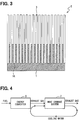
- the heat storage unit 5 As a configuration of the heat storage unit, for example, as illustrated in FIGS. 2 and 3 , there is a heat storage unit 5 having a laminated structure in which multiple members of the heat storage portion 1 and multiple members of the heat conduction portion 3 are alternately stacked on each other.
- the heat storage portion 1 and the heat conduction portion 3 are each divided into multiple plate members, which are alternately stacked on each other.
- multiple concave portions 1A are periodically provided in a part of the heat storage portion 1, and multiple plate-shaped heat conduction portions 3 are inserted into the respective multiple concave portions 1A, resulting in a laminated structure in which the multiple concave portions 1A of the heat storage portion 1 and the heat conduction portions 3 are alternately stacked on each other.
- the heat storage unit transfers the heat of the heat transport medium to the heat storage portion through the heat conduction portion having a second material having a thermal conductivity higher than that of the first material. Therefore, the heat storage unit can efficiently store the heat of the heat transport medium.
- the heat storage unit has a laminated structure in which the heat storage portion 1 and the heat conduction portion(s) 3 are alternately laminated on each other as illustrated in FIGS. 2 and 3 , for example, the heat can be efficiently transferred to the inside of the heat storage portion 1.
- the strongly correlated electron system material has a large amount of heat storage per unit volume. Because the heat storage portion in the heat storage unit according to the present disclosure has the first material including the strongly correlated electron system material, the heat storage amount per unit volume is large.
- a heat storage system includes a first space and a second space partitioned by a partition wall.
- the first space and the second space there are spaces individually partitioned such that an interior of a pipe is divided into two or more spaces by partition walls extending along an axial direction of the pipe.
- first space and the second space may be provided by dividing an open space by partition walls.
- the first space and the second space may be completely separated from each other by a partition wall or may partially communicate with each other.
- the partition wall contains a heat insulating material.
- a heat insulating material there are, for example, foamed resin, glass wool, and the like.
- the heat storage system includes a rotating unit.
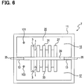
- a rotating unit 27 is placed across a first space 15 and a second space 17.
- at the time of using the heat storage system at least one part of the rotating unit is placed in the first space and at least another part of the rotating unit is placed in the second space.
- the rotating unit is rotatable around a rotary shaft 35 that is in parallel to a partition wall 13.
- the rotating unit can be disposed, for example, in a place where the partition wall 13 is not partially present.
- a portion of the partition wall 13 divided from the other portion may configure a part of the rotating unit 27.
- the rotating unit 27 includes heat storage units 31 and 33 which are placed in the first space 15 and the second space 17, respectively, and have the same configuration as that of the heat storage unit 5 in the first embodiment.
- the rotating unit 27 includes the heat storage unit 31 exposed to the first space 15, and the heat storage unit 33 exposed to the second space 17.
- FIG. 9 when the rotating unit 27 rotates, the heat storage unit 31 that has been placed in the first place 15 moves toward the second space 17 while the heat storage unit 33 that has been placed in the second space 17 moves toward the first space 15.
- the rotating unit 27 further rotates, the heat storage unit 33 that has been placed in the first space 15 moves toward the second space 17 while the heat storage unit 31 that has been placed in the second space 17 moves toward the first space 15.
- the rotating unit is provided with a heat insulating material between the heat storage unit in the first space and the heat storage unit in the second space.
- the heat insulating material may employ, for example, foamed resin, glass wool, and the like.
- the rotating unit can be rotated by a driving force of a driving source such as a motor, an internal combustion engine, or the like, for example.
- the rotation of the rotating unit may be executed in response to a signal from a control unit provided in the heat storage system or an external control unit, or may be executed according to user's operation.
- the heat storage system may be equipped with a measurement unit that measures at least any one of a temperature of the heat storage unit in the first space, a temperature of the heat storage unit in the second space, a temperature difference between the heat storage unit in the first space and a heat transport medium flowing through the first space, and a temperature difference between the heat storage unit in the second space and the heat transport medium flowing through the second space.
- the control unit described above may output a signal for rotating the rotating unit on condition that the above-mentioned any temperature or temperature difference measured by the measurement unit has reached a reference value.
- the rotating unit may be rotated manually by the user. Also, the rotating unit may automatically rotate at regular time intervals.
- FIG. 4 A specific example of a heat storage system 7 will be described with reference to FIGS. 4 to 9 .
- an exhaust gas 101 discharged from an energy converter 9 passes through the heat storage system 7.
- the heat storage system 7 accumulates a heat of the exhaust gas 101.
- a coolant water 103 in the energy converter 9 has a circulation path that passes through an inside of the heat storage system 7.
- the heat storage system 7 releases the accumulated heat to the coolant water 103 and raises a temperature of the coolant water 103.
- the energy converter 9 is, for example, an internal combustion engine or a fuel cell.
- the heat storage system 7 includes a pipe 11.
- the inside of the pipe 11 is partitioned into upper and lower parts by the partition wall 13 extending along an axial direction of the pipe 11.
- a space above the partition wall 13 in FIG. 5 is defined as the first space 15, and a space below the partition wall 13 is defined as the second space 17.
- the partition wall 13 is made of a heat insulating material.
- the first space 15 is a flow channel of the exhaust gas 101 and the second space 17 is a flow channel of the coolant water 103.
- the exhaust gas 101 and the coolant water 103 are examples of a heat transport medium.
- a temperature of the exhaust gas 101 is higher than a temperature of the coolant water 103.
- a direction in which the exhaust gas 101 flows and a direction in which the coolant water 103 flows are opposite to each other.
- the pipe 11 has opening and closing doors 19 and 21 at two places.
- the opening and closing doors 19 and 21 are shutter type doors and open and close the pipe 11. When the opening and closing doors 19 and 21 are opened, both of the first space 15 and the second space 17 are opened. On the other hand, when the opening and closing doors 19 and 21 are closed, both of the first space 15 and the second space 17 are closed.
- the pipe 11 is provided with a bypass portion 23 that connects a front side of the opening and closing door 19 and a back side of the opening and closing door 21 in FIG. 5 .
- the interior of the bypass portion 23 is partitioned into the first space 15 and the second space 17 by the partition wall 13 in the same manner as that of the other portions of the pipe 11.
- the exhaust gas 101 flowing through the first space 15 can flow through both of a region (hereinafter referred to as "main flow channel 25") sandwiched between the opening and closing doors 19 and 21, and the bypass portion 23.
- the exhaust gas 101 mainly flows through the main flow channel 25 having a lower resistance.
- the opening and closing doors 19 and 21 are closed, the exhaust gas 101 flowing through the first space 15 does not flow through the main flow channel 25 but flows through the bypass portion 23.
- the coolant water 103 flowing through the second space 17 mainly flows through the main flow channel 25, and when the opening and closing doors 19 and 21 are closed, the coolant water 103 does not flow through the main flow channel 25, but flows through the bypass portion 23.
- the heat storage system 7 is equipped with the rotating unit 27 in the main flow channel 25 of the pipe 11.
- the rotating unit 27 includes a plate-shaped seat 29, a heat storage unit 31 installed on one surface of the seat 29, a heat storage unit 33 installed on an opposite surface of the seat 29.
- the seat 29 is made of a heat insulating material.
- the rotating unit 27 is provided across the first space 15 and the second space 17.
- Each of the heat storage units 31 and 33 has a laminated structure in which plate-shaped heat storage portions 1 and plate-shaped heat conduction portions 3 are alternately laminated on each other.
- a stacking direction of the heat storage portions 1 and the heat conduction portions 3 is in parallel to the partition wall 13 and is orthogonal to the flow direction of the exhaust gas 101 and the coolant water 103.
- a height of the heat conduction portions 3 is larger than the height of the heat storage portions 1.
- the heat storage portions 1 are made of VO 2
- the heat conduction portions 3 are made of copper.
- the partition wall 13 is notched in a rectangular shape in a portion where the rotating unit 27 is present, and the seat 29 is fitted into the notched portion.
- the seat 29 has the rotary shaft 35 penetrating through the seat 29 in a lateral direction (direction perpendicular to the axial direction of the pipe 11).
- the rotary shaft 35 passes through an inside of the partition wall 13 on both sides of the seat 29 and reaches an outside of the pipe 11.
- the axial direction of the rotary shaft 35 is in parallel to a surface of the partition wall 13.
- the rotating unit 27 is rotatable around the rotary shaft 35.
- the seat 29 and the partition wall 13 are flush with each other.
- one of the heat storage units 31 and 33 is placed in the first space 15 and the other is placed in the second space 17.
- the opening and closing doors 19 and 21 are in an opened state.
- the heat storage system 7 can rotate the rotating unit 27 around the rotary shaft 35.
- the heat storage unit that has been placed in the first space 15 can be moved to the second space 17, and the heat storage unit that has been placed in the second space 17 can moved to the first space 15.
- the opening and closing doors 19 and 21 are kept in a closed state.
- the heat storage system 7 puts the opening and closing doors 19 and 21 in the open state, allows the exhaust gas 101 to flow through the main flow channel 25, and accumulates the heat of the exhaust gas 101 in the heat storage unit placed in the first space 15. Then, after the heat storage system 7 puts the opening and closing doors 19 and 21 in a closed state, the heat storage system 7 rotates the rotating unit 27 by 180°. Then, the heat storage unit that has been placed in the first space 15 moves toward the second space 17, and the heat storage unit releases the heat that has been accumulated to the coolant water 103 in the second space 17. On the other hand, the heat storage unit which has been placed in the second space 17 just before the rotation of the rotating unit 27 (i.e. the heat storage unit which has been cooled by the coolant water 103) moves toward the first space 15, and the heat storage unit accumulates the heat of the exhaust gas 101 in the first space 15.
- the heat storage system includes the above-described heat storage unit, the heat storage system obtains the advantages of the heat storage unit.
- the heat storage system can keep the high thermal conductivity between the heat storage unit and the heat transport medium.
- a high-temperature heat transport medium for example, exhaust gas 101
- a low-temperature heat transport medium for example, coolant water 103
- the heat storage unit 31 in the first space 15 absorbs the heat from the high-temperature heat transport medium and the heat storage unit in the second space 17 releases the heat to the low-temperature heat transport medium.
- the heat storage system 7 rotates the rotating unit 27. Accordingly, the heat storage unit 31 that has been located in the first space 15 can be moved to the second space 17 and the heat storage unit 33 that has been previously located in the second space 17 can be moved to the first space 15.
- the low-temperature heat storage unit 33 since the low-temperature heat storage unit 33 is located in the first space 15, the temperature difference between the heat storage unit 33 in the first space 15 and the high-temperature heat transport medium increases, and the heat flow between the heat storage unit 33 and the high-temperature heat transport medium is recovered.
- the high-temperature heat storage unit 31 since the high-temperature heat storage unit 31 is located in the second space 17, the temperature difference between the heat storage unit 31 in the second space 17 and the low-temperature heat transport medium increases, and the heat flow between the heat storage unit 31 and the low-temperature heat transport medium is recovered.
- a heat storage unit 5 has a form in which multiple heat conduction portions 3 are buried in a heat storage portion 1.
- the heat conduction portion 3 has a straight bar shape.
- the heat storage portion 1 has a rectangular parallelepiped shape.
- the heat conduction portions 3 appear on an upper surface 1 B of the heat storage portion 1 and a bottom surface 1C on the opposite side of the upper surface 1 B.
- the heat storage portion 1 and the heat conduction portions 3 can be made of the same material as those of the first embodiment.
- the configuration of the heat storage unit 5 may be other than that illustrated in FIG. 10 .
- the heat conduction portions 3 may be formed in a curved bar shape, a zigzag type rod shape, or the like.
- the number of the heat conduction portions 3 may be one.
- the heat conduction portion 3 may appear on one surface (for example, the upper surface 1 B) of the surfaces of the heat storage portion 1 but not appear on the other surface.
- the axial directions of the multiple heat conduction portions 3 may be nonparallel to each other.
- the shape of the heat storage portion 1 may be a shape other than a rectangular parallelepiped shape (for example, a columnar shape, a spherical shape, etc.).
- the heat storage unit 5 includes the heat conduction portions 3 having a second material having a thermal conductivity higher than that of the first material. Most of the heat conduction portions 3 are buried in the heat storage portion 1 and the heat conduction portions 3 appear on at least one of the surfaces of the heat storage portion 1.
- the heat storage unit 5 receives the heat of the heat transport medium at a portion of the heat conduction portions 3 appearing on the surface of the heat storage portion 1 and transfers the heat to the inside of the heat storage portion 1 through the heat conduction portions 3. Therefore, the heat storage unit 5 can efficiently store the heat of the heat transport medium.
- the strongly correlated electron system material has a large amount of heat storage per unit volume. Because the heat storage portion 1 in the heat storage unit 5 has the first material including the strongly correlated electron system material, the heat storage amount per unit volume is large.
- a function of one constituent element in the above-described embodiments may be distributed to a plurality of constituent elements, or functions of a plurality of constituent elements may be integrated into one constituent element.
- at least a part of the above-described embodiments may be switched to a known configuration having similar effects. A part of the configuration according to the above-described embodiment may be omitted. Also, at least a part of the configuration in the above embodiments may be added to or replaced with another configuration in the above embodiments.
- the present disclosure can be realized in various configurations such as a heat storage method.
Landscapes
- Engineering & Computer Science (AREA)
- Chemical & Material Sciences (AREA)
- Physics & Mathematics (AREA)
- Thermal Sciences (AREA)
- Mechanical Engineering (AREA)
- General Engineering & Computer Science (AREA)
- Chemical Kinetics & Catalysis (AREA)
- Combustion & Propulsion (AREA)
- Materials Engineering (AREA)
- Organic Chemistry (AREA)
- Cooling Or The Like Of Electrical Apparatus (AREA)
- Air-Conditioning For Vehicles (AREA)
Abstract
Description
- This application is based on and incorporates herein by reference Japanese Patent Application No.
2014-201437 filed on September 30, 2014 - The present disclosure relates to a heat storage unit and a heat storage system.
- Up to now, a heat storage material made of material that undergoes an electron phase transition has been known (refer to Patent Document 1). The heat storage material utilizes an enthalpy change associated with the electron phase transition for heat storage. However, the heat storage material described in
Patent Document 1 has insufficient thermal conductivity. Therefore, heat of a heat transport medium cannot be efficiently stored in the heat storage material in some cases. - Patent Document 1 :
JP 2010-163510 A - An object of the present disclosure is to provide a heat storage unit and a heat storage system capable of efficiently storing heat of a heat transport medium.
- According to one aspect of the present disclosure, a heat storage unit includes a heat storage portion having a first material including a strongly correlated electron system material, and a heat conduction portion including a second material that is higher in thermal conductivity than the first material and the heat conduction portion is in contact with the heat storage portion.
- The heat storage unit according to the present disclosure can transfer the heat of the heat transport medium to the heat storage portion through the heat conduction portion having a second material having a thermal conductivity higher than that of the first material. Therefore, the heat storage unit according to the present disclosure can efficiently store the heat of the heat transport medium.
-
-
FIG. 1 is a schematic diagram illustrating a heat storage unit according to a first embodiment of the present disclosure. -
FIG. 2 is a schematic diagram illustrating one example of the heat storage unit according to the first embodiment. -
FIG. 3 is a schematic diagram illustrating another example of the heat storage unit according to the first embodiment. -
FIG. 4 is a schematic diagram illustrating an arrangement of a heat storage system according to a second embodiment of the present disclosure. -
FIG. 5 is a perspective view illustrating the heat storage system according to the second embodiment. -
FIG. 6 is a cross-sectional view taken along a line VI-VI inFIG. 5 . -
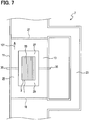
FIG. 7 is a cross-sectional view taken along a line VII-VII inFIG. 5 . -
FIG. 8 is a cross-sectional view taken along a line VIII-VIII inFIG. 5 . -
FIG. 9 is a schematic view illustrating a state in which a rotating unit rotates according to the second embodiment. -
FIG. 10 is a schematic diagram illustrating a heat storage unit according to a third embodiment of the present disclosure. - Hereinafter, multiple embodiments for implementing the present invention will be described referring to drawings. In the respective embodiments, a part that corresponds to a matter described in a preceding embodiment may be assigned the same reference numeral, and redundant explanation for the part may be omitted. When only a part of a configuration is described in an embodiment, another preceding embodiment may be applied to the other parts of the configuration. The parts may be combined even if it is not explicitly described that the parts can be combined. The embodiments may be partially combined even if it is not explicitly described that the embodiments can be combined, provided there is no harm in the combination.
- A heat storage unit according to a first embodiment of the present disclosure includes a heat storage portion having a first material with a strongly correlated electron system material. The first material may be a material consisting of a strongly correlated electron system material or may further contain other components. The heat storage portion may be made of only the first material.
- A strongly correlated electron system material has a system in which at least one of degrees of freedom, i.e. spin, orbit and charge, of electrons becomes manifested by a strong coulomb repulsion between the electrons. The manifested respective degrees of freedom: the spin, orbit and charge, show a large entropy change associated with a change in number of states in accordance with an order-disorder phase transition (the phase transition of the manifested degrees of freedom: spin, orbit and charge, is called "electron phase transition").
- As the strongly correlated electron system material, there is, for example, one that undergoes a metal-insulator phase transition. As a strongly correlated electron system material, there is, for example, a transition metal oxide.
- Specific examples of the strongly correlated electron system material are V(1-X) WXO2 (0 ≤ X ≤ 0.0650), V(1-X) TaXO2 (0 ≤ X ≤ 0.117), V(1-X) NbXO2 (0 ≤ X ≤ 0.115), V(1-X) RuXO2 (0 ≤ X ≤ 0.150), V(1-X) MoXO2 (0 ≤ X ≤ 0.161), V(1-X) ReXO2 (0 ≤ X ≤ 0.0964), LiMn2O4, LiVS2, LiVO2, NaNiO2, LiRh2O4, V2O3, V4O7, V6O11, Ti4O7, SmBaFe2O5, EuBaFe2O5, GdBaFe2O5, TbBaFe2O5, DyBaFe2O5, HoBaFe2O5, YBaFe2O5, PrBaCo2O5.5, DyBaCo2O5.54, HoBaCo2O5.48, YBaCo2O5.49, and the like. All of those materials undergo the metal-insulator phase transition and are transition metal oxides.
- For example, the heat storage portion can be manufactured in a method in which a jig is filled with a powder of the first material, and the powder of the first material is then sintered by a technique such as a hot press, a spark plasma sintering (SPS), a hot isostatic pressurization method (HIP).
- The heat storage unit according to the present disclosure includes a heat conduction portion. The heat conduction portion has a second material having a thermal conductivity higher than that of the first material and comes in contact with the heat storage portion. Examples of the second material include metal, ceramics and the like. Examples of the metal include aluminum, gold, silver, copper, iron, stainless steel, brass, titanium, and alloys of those materials. A shape of the heat conduction portion is not particularly limited. For example, as illustrated in
FIG. 1 , aheat conduction portion 3 may have a fin shape. Theheat conduction portion 3 may consist of only the second material. - The second material may consist of a single component or may include two or more components (for example, alloy). Further, the heat conduction portion may be formed of a single component or multiple components, for example. In the case where the heat conduction portion is formed of the multiple components, the second material configuring each part may be the same as or different from each other.
- As one configuration of the heat storage unit, for example, as illustrated in
FIG. 1 , there is aheat storage unit 5 in which aheat storage portion 1 and theheat conduction portion 3 are integrated together. As another configuration of the heat storage unit, for example, as illustrated inFIG. 1 , there is theheat storage unit 5 in which the singleheat storage portion 1 is enclosed with theheat conduction portion 3. - As a configuration of the heat storage unit, for example, as illustrated in
FIGS. 2 and3 , there is aheat storage unit 5 having a laminated structure in which multiple members of theheat storage portion 1 and multiple members of theheat conduction portion 3 are alternately stacked on each other. In theheat storage unit 5 having a configuration illustrated inFIG. 2 , theheat storage portion 1 and theheat conduction portion 3 are each divided into multiple plate members, which are alternately stacked on each other. - Further, in the
heat storage unit 5 of the configuration illustrated inFIG. 3 , multipleconcave portions 1A are periodically provided in a part of theheat storage portion 1, and multiple plate-shapedheat conduction portions 3 are inserted into the respective multipleconcave portions 1A, resulting in a laminated structure in which the multipleconcave portions 1A of theheat storage portion 1 and theheat conduction portions 3 are alternately stacked on each other. - The advantages of the heat storage unit will be described below. The heat storage unit transfers the heat of the heat transport medium to the heat storage portion through the heat conduction portion having a second material having a thermal conductivity higher than that of the first material. Therefore, the heat storage unit can efficiently store the heat of the heat transport medium.
- Furthermore, in the case where the heat storage unit has a laminated structure in which the
heat storage portion 1 and the heat conduction portion(s) 3 are alternately laminated on each other as illustrated inFIGS. 2 and3 , for example, the heat can be efficiently transferred to the inside of theheat storage portion 1. - Also, the strongly correlated electron system material has a large amount of heat storage per unit volume. Because the heat storage portion in the heat storage unit according to the present disclosure has the first material including the strongly correlated electron system material, the heat storage amount per unit volume is large.
- A heat storage system according to the present disclosure includes a first space and a second space partitioned by a partition wall. As an example of the first space and the second space, there are spaces individually partitioned such that an interior of a pipe is divided into two or more spaces by partition walls extending along an axial direction of the pipe.
- In addition, the first space and the second space may be provided by dividing an open space by partition walls. The first space and the second space may be completely separated from each other by a partition wall or may partially communicate with each other.
- It is preferable that at least a part of the partition wall contains a heat insulating material. In that case, heat conduction between the first space and the second space can be suppressed. As the heat insulating material, there are, for example, foamed resin, glass wool, and the like.
- The heat storage system according to the present disclosure includes a rotating unit. For example, as illustrated in
FIGS. 6 and8 , a rotatingunit 27 is placed across afirst space 15 and asecond space 17. In other words, at the time of using the heat storage system, at least one part of the rotating unit is placed in the first space and at least another part of the rotating unit is placed in the second space. - As illustrated in
FIG. 9 , for example, the rotating unit is rotatable around arotary shaft 35 that is in parallel to apartition wall 13. The rotating unit can be disposed, for example, in a place where thepartition wall 13 is not partially present. In addition, a portion of thepartition wall 13 divided from the other portion may configure a part of the rotatingunit 27. - As illustrated in
FIGS. 6 and8 , for example, the rotatingunit 27 includesheat storage units first space 15 and thesecond space 17, respectively, and have the same configuration as that of theheat storage unit 5 in the first embodiment. In other words, the rotatingunit 27 includes theheat storage unit 31 exposed to thefirst space 15, and theheat storage unit 33 exposed to thesecond space 17. For example, as illustrated inFIG. 9 , when the rotatingunit 27 rotates, theheat storage unit 31 that has been placed in thefirst place 15 moves toward thesecond space 17 while theheat storage unit 33 that has been placed in thesecond space 17 moves toward thefirst space 15. When therotating unit 27 further rotates, theheat storage unit 33 that has been placed in thefirst space 15 moves toward thesecond space 17 while theheat storage unit 31 that has been placed in thesecond space 17 moves toward thefirst space 15. - It is preferable that the rotating unit is provided with a heat insulating material between the heat storage unit in the first space and the heat storage unit in the second space. In that case, heat conduction from one heat storage unit to the other heat storage unit can be reduced. The heat insulating material may employ, for example, foamed resin, glass wool, and the like.
- The rotating unit can be rotated by a driving force of a driving source such as a motor, an internal combustion engine, or the like, for example. The rotation of the rotating unit may be executed in response to a signal from a control unit provided in the heat storage system or an external control unit, or may be executed according to user's operation.
- For example, the heat storage system may be equipped with a measurement unit that measures at least any one of a temperature of the heat storage unit in the first space, a temperature of the heat storage unit in the second space, a temperature difference between the heat storage unit in the first space and a heat transport medium flowing through the first space, and a temperature difference between the heat storage unit in the second space and the heat transport medium flowing through the second space. In that case, for example, the control unit described above may output a signal for rotating the rotating unit on condition that the above-mentioned any temperature or temperature difference measured by the measurement unit has reached a reference value. Also, the rotating unit may be rotated manually by the user. Also, the rotating unit may automatically rotate at regular time intervals.
- A specific example of a
heat storage system 7 will be described with reference toFIGS. 4 to 9 . As illustrated inFIG. 4 , anexhaust gas 101 discharged from anenergy converter 9 passes through theheat storage system 7. At that time, theheat storage system 7 accumulates a heat of theexhaust gas 101. - A
coolant water 103 in theenergy converter 9 has a circulation path that passes through an inside of theheat storage system 7. When thecoolant water 103 passes through the inside of theheat storage system 7, theheat storage system 7 releases the accumulated heat to thecoolant water 103 and raises a temperature of thecoolant water 103. With an increase in the temperature of thecoolant water 103, theenergy converter 9 can be smoothly started. Theenergy converter 9 is, for example, an internal combustion engine or a fuel cell. - As illustrated in
FIG. 5 , theheat storage system 7 includes apipe 11. The inside of thepipe 11 is partitioned into upper and lower parts by thepartition wall 13 extending along an axial direction of thepipe 11. In the following descriptions, in the inside of thepipe 11, a space above thepartition wall 13 inFIG. 5 is defined as thefirst space 15, and a space below thepartition wall 13 is defined as thesecond space 17. Thepartition wall 13 is made of a heat insulating material. - The
first space 15 is a flow channel of theexhaust gas 101 and thesecond space 17 is a flow channel of thecoolant water 103. Theexhaust gas 101 and thecoolant water 103 are examples of a heat transport medium. A temperature of theexhaust gas 101 is higher than a temperature of thecoolant water 103. A direction in which theexhaust gas 101 flows and a direction in which thecoolant water 103 flows are opposite to each other. - The
pipe 11 has opening andclosing doors closing doors pipe 11. When the opening andclosing doors first space 15 and thesecond space 17 are opened. On the other hand, when the opening andclosing doors first space 15 and thesecond space 17 are closed. - The
pipe 11 is provided with abypass portion 23 that connects a front side of the opening and closingdoor 19 and a back side of the opening and closingdoor 21 inFIG. 5 . The interior of thebypass portion 23 is partitioned into thefirst space 15 and thesecond space 17 by thepartition wall 13 in the same manner as that of the other portions of thepipe 11. - When the opening and
closing doors exhaust gas 101 flowing through thefirst space 15 can flow through both of a region (hereinafter referred to as "main flow channel 25") sandwiched between the opening andclosing doors bypass portion 23. However, theexhaust gas 101 mainly flows through themain flow channel 25 having a lower resistance. On the other hand, when the opening andclosing doors exhaust gas 101 flowing through thefirst space 15 does not flow through themain flow channel 25 but flows through thebypass portion 23. - Similarly, when the opening and
closing doors coolant water 103 flowing through thesecond space 17 mainly flows through themain flow channel 25, and when the opening andclosing doors coolant water 103 does not flow through themain flow channel 25, but flows through thebypass portion 23. - The
heat storage system 7 is equipped with the rotatingunit 27 in themain flow channel 25 of thepipe 11. As illustrated inFIGS. 6 to 9 , the rotatingunit 27 includes a plate-shapedseat 29, aheat storage unit 31 installed on one surface of theseat 29, aheat storage unit 33 installed on an opposite surface of theseat 29. Theseat 29 is made of a heat insulating material. The rotatingunit 27 is provided across thefirst space 15 and thesecond space 17. - Each of the
heat storage units heat storage portions 1 and plate-shapedheat conduction portions 3 are alternately laminated on each other. A stacking direction of theheat storage portions 1 and theheat conduction portions 3 is in parallel to thepartition wall 13 and is orthogonal to the flow direction of theexhaust gas 101 and thecoolant water 103. When theseat 29 is used as a reference, a height of theheat conduction portions 3 is larger than the height of theheat storage portions 1. Theheat storage portions 1 are made of VO2, and theheat conduction portions 3 are made of copper. - As illustrated in
FIG. 7 , thepartition wall 13 is notched in a rectangular shape in a portion where the rotatingunit 27 is present, and theseat 29 is fitted into the notched portion. Theseat 29 has therotary shaft 35 penetrating through theseat 29 in a lateral direction (direction perpendicular to the axial direction of the pipe 11). Therotary shaft 35 passes through an inside of thepartition wall 13 on both sides of theseat 29 and reaches an outside of thepipe 11. The axial direction of therotary shaft 35 is in parallel to a surface of thepartition wall 13. The rotatingunit 27 is rotatable around therotary shaft 35. - Normally, as illustrated in
FIGS. 6 and8 , theseat 29 and thepartition wall 13 are flush with each other. In this case, one of theheat storage units first space 15 and the other is placed in thesecond space 17. In this case, the opening andclosing doors - On the other hand, as illustrated in
FIG. 9 , theheat storage system 7 can rotate therotating unit 27 around therotary shaft 35. The heat storage unit that has been placed in thefirst space 15 can be moved to thesecond space 17, and the heat storage unit that has been placed in thesecond space 17 can moved to thefirst space 15. In this situation, the opening andclosing doors - The
heat storage system 7 puts the opening andclosing doors exhaust gas 101 to flow through themain flow channel 25, and accumulates the heat of theexhaust gas 101 in the heat storage unit placed in thefirst space 15. Then, after theheat storage system 7 puts the opening andclosing doors heat storage system 7 rotates the rotatingunit 27 by 180°. Then, the heat storage unit that has been placed in thefirst space 15 moves toward thesecond space 17, and the heat storage unit releases the heat that has been accumulated to thecoolant water 103 in thesecond space 17. On the other hand, the heat storage unit which has been placed in thesecond space 17 just before the rotation of the rotating unit 27 (i.e. the heat storage unit which has been cooled by the coolant water 103) moves toward thefirst space 15, and the heat storage unit accumulates the heat of theexhaust gas 101 in thefirst space 15. - The advantages of the heat storage system will be described below. Since the heat storage system includes the above-described heat storage unit, the heat storage system obtains the advantages of the heat storage unit.
- Furthermore, with the rotation of the rotating unit, the heat storage system can keep the high thermal conductivity between the heat storage unit and the heat transport medium. This configuration will be described below. For example, as illustrated in
FIGS. 6 and8 , it is assumed that a high-temperature heat transport medium (for example, exhaust gas 101) flows in thefirst space 15, a low-temperature heat transport medium (for example, coolant water 103) flows in thesecond space 17. Theheat storage unit 31 in thefirst space 15 absorbs the heat from the high-temperature heat transport medium and the heat storage unit in thesecond space 17 releases the heat to the low-temperature heat transport medium. - As time passes, the temperature of the
heat storage unit 31 in thefirst space 15 rises, and a temperature difference from the high temperature heat transport medium decreases. Therefore, a heat flow between theheat storage unit 31 in thefirst space 15 and the high-temperature heat transport medium decreases as time passes. - As time passes, the temperature of the
heat storage unit 33 in thesecond space 17 drops, and a temperature difference from the low-temperature heat transport medium decreases. Therefore, a heat flow between theheat storage unit 33 in thesecond space 17 and the low-temperature heat transport medium also decreases as time passes. - As described above, when the heat flow in the
heat storage units first space 15 and thesecond space 17 decreases, theheat storage system 7 rotates the rotatingunit 27. Accordingly, theheat storage unit 31 that has been located in thefirst space 15 can be moved to thesecond space 17 and theheat storage unit 33 that has been previously located in thesecond space 17 can be moved to thefirst space 15. - In this way, since the low-temperature
heat storage unit 33 is located in thefirst space 15, the temperature difference between theheat storage unit 33 in thefirst space 15 and the high-temperature heat transport medium increases, and the heat flow between theheat storage unit 33 and the high-temperature heat transport medium is recovered. In addition, since the high-temperatureheat storage unit 31 is located in thesecond space 17, the temperature difference between theheat storage unit 31 in thesecond space 17 and the low-temperature heat transport medium increases, and the heat flow between theheat storage unit 31 and the low-temperature heat transport medium is recovered. - With the repetition of the above operation, the large heat flow between the
heat storage units - As illustrated in
FIG. 10 , aheat storage unit 5 according to the present embodiment has a form in which multipleheat conduction portions 3 are buried in aheat storage portion 1. Theheat conduction portion 3 has a straight bar shape. Theheat storage portion 1 has a rectangular parallelepiped shape. Theheat conduction portions 3 appear on anupper surface 1 B of theheat storage portion 1 and abottom surface 1C on the opposite side of theupper surface 1 B. Theheat storage portion 1 and theheat conduction portions 3 can be made of the same material as those of the first embodiment. - The configuration of the
heat storage unit 5 may be other than that illustrated inFIG. 10 . For example, theheat conduction portions 3 may be formed in a curved bar shape, a zigzag type rod shape, or the like. Also, the number of theheat conduction portions 3 may be one. Further, theheat conduction portion 3 may appear on one surface (for example, theupper surface 1 B) of the surfaces of theheat storage portion 1 but not appear on the other surface. In addition, the axial directions of the multipleheat conduction portions 3 may be nonparallel to each other. Further, the shape of theheat storage portion 1 may be a shape other than a rectangular parallelepiped shape (for example, a columnar shape, a spherical shape, etc.). - The advantages of the
heat storage unit 5 will be described below. Theheat storage unit 5 includes theheat conduction portions 3 having a second material having a thermal conductivity higher than that of the first material. Most of theheat conduction portions 3 are buried in theheat storage portion 1 and theheat conduction portions 3 appear on at least one of the surfaces of theheat storage portion 1. Theheat storage unit 5 receives the heat of the heat transport medium at a portion of theheat conduction portions 3 appearing on the surface of theheat storage portion 1 and transfers the heat to the inside of theheat storage portion 1 through theheat conduction portions 3. Therefore, theheat storage unit 5 can efficiently store the heat of the heat transport medium. - Also, the strongly correlated electron system material has a large amount of heat storage per unit volume. Because the
heat storage portion 1 in theheat storage unit 5 has the first material including the strongly correlated electron system material, the heat storage amount per unit volume is large. - The embodiments of the present disclosure have been described above. However, the present disclosure is not limited to the above embodiments, but can be variously embodied.
- In addition, a function of one constituent element in the above-described embodiments may be distributed to a plurality of constituent elements, or functions of a plurality of constituent elements may be integrated into one constituent element. In addition, at least a part of the above-described embodiments may be switched to a known configuration having similar effects. A part of the configuration according to the above-described embodiment may be omitted. Also, at least a part of the configuration in the above embodiments may be added to or replaced with another configuration in the above embodiments.
- In addition to the above-described heat storage unit and heat storage system, the present disclosure can be realized in various configurations such as a heat storage method.
- While the present disclosure has been described with reference to embodiments thereof, it is to be understood that the disclosure is not limited to the embodiments and constructions. To the contrary, the present disclosure is intended to cover various modification and equivalent arrangements. In addition, while the various elements of the disclosure are shown in various combinations and configurations, which are exemplary, other combinations and configurations, including more, less or only a single element, are also within the spirit and scope of the present disclosure.
Claims (6)
- A heat storage unit (5, 31, 33) comprising:a heat storage portion (1) comprising a first material including a strongly correlated electron system material; anda heat conduction portion (3) comprising a second material that is higher in thermal conductivity than the first material, the heat conduction portion being in contact with the heat storage portion.
- The heat storage unit according to claim 1, wherein
the heat storage portion includes a plurality of members,
the heat conduction portion includes a plurality of members, and
the plurality of members of the heat storage portion and the plurality of members of the heat conduction portion are alternately laminated. - The heat storage unit according to claim 1 or 2, wherein
the strongly correlated electron system material is a material that undergoes a metal-insulator phase transition. - The heat storage unit according to any one of claims 1 to 3, wherein
the strongly correlated electron system material is a transition metal oxide. - The heat storage unit according to any one of claims 1 to 4, wherein
the second material is a metal or a ceramic. - A heat storage system (7) comprising:a partition wall (13);a first space (15) and a second space (17) which are partitioned by the partition wall; anda rotating unit (27) provided across the first space and the second space and being rotatable about a rotary shaft (35) that is parallel to the partition wall, whereinthe rotating unit includes two heat storage units (31, 33) according to any one of claims 1 to 5, andone of the two heat storage units is exposed to the first space, andthe other of the two heat storage units is exposed to the second space.
Applications Claiming Priority (2)
| Application Number | Priority Date | Filing Date | Title |
|---|---|---|---|
| JP2014201437A JP6409465B2 (en) | 2014-09-30 | 2014-09-30 | Heat storage system |
| PCT/JP2015/004817 WO2016051728A1 (en) | 2014-09-30 | 2015-09-22 | Heat storage unit and heat storage system |
Publications (3)
| Publication Number | Publication Date |
|---|---|
| EP3203172A1 true EP3203172A1 (en) | 2017-08-09 |
| EP3203172A4 EP3203172A4 (en) | 2017-10-18 |
| EP3203172B1 EP3203172B1 (en) | 2021-05-19 |
Family
ID=55629799
Family Applications (1)
| Application Number | Title | Priority Date | Filing Date |
|---|---|---|---|
| EP15846449.5A Active EP3203172B1 (en) | 2014-09-30 | 2015-09-22 | Heat storage system |
Country Status (5)
| Country | Link |
|---|---|
| US (1) | US10126072B2 (en) |
| EP (1) | EP3203172B1 (en) |
| JP (1) | JP6409465B2 (en) |
| CN (1) | CN107076524B (en) |
| WO (1) | WO2016051728A1 (en) |
Cited By (1)
| Publication number | Priority date | Publication date | Assignee | Title |
|---|---|---|---|---|
| EP4151696A4 (en) * | 2020-05-14 | 2024-05-29 | National Institute Of Advanced Industrial Science and Technology | SOLID HEAT ACCUMULATOR MATERIAL WITH REGULATED THERMAL CONDUCTIVITY AND COMPOSITE |
Families Citing this family (2)
| Publication number | Priority date | Publication date | Assignee | Title |
|---|---|---|---|---|
| JP6593266B2 (en) | 2016-07-20 | 2019-10-23 | 株式会社デンソー | Vehicle warm-up device |
| CA3137502A1 (en) * | 2019-04-26 | 2020-10-29 | Energy Systems Management Limited | Caloric store |
Family Cites Families (29)
| Publication number | Priority date | Publication date | Assignee | Title |
|---|---|---|---|---|
| US2846195A (en) * | 1946-02-04 | 1958-08-05 | Power Jets Res & Dev Ltd | Heat exchangers |
| US2667034A (en) * | 1946-04-01 | 1954-01-26 | Power Jets Res & Dev Ltd | Air turbine power plant having rotary regenerator to transfer heat from an afterburner to the motive fluid |
| US3444925A (en) * | 1957-05-07 | 1969-05-20 | Minnesota Mining & Mfg | Structural articles and method of making |
| US3478816A (en) * | 1968-02-19 | 1969-11-18 | Gen Motors Corp | Regenerator matrix |
| JPS57150796A (en) * | 1981-03-11 | 1982-09-17 | Kansai Kennetsu Kogyo Kk | Rotary heat exchanger |
| JPH0523979Y2 (en) * | 1985-08-30 | 1993-06-18 | ||
| US5323842A (en) * | 1992-06-05 | 1994-06-28 | Wahlco Environmental Systems, Inc. | Temperature-stabilized heat exchanger |
| US6004662A (en) * | 1992-07-14 | 1999-12-21 | Buckley; Theresa M. | Flexible composite material with phase change thermal storage |
| JP3004893B2 (en) * | 1995-06-02 | 2000-01-31 | 日本フレクト株式会社 | Rotary heat exchanger |
| EP1471324A3 (en) * | 2003-04-22 | 2005-11-16 | Matsushita Electric Industrial Co., Ltd. | Thermal storage apparatus and thermal storage method |
| US7571758B2 (en) * | 2004-01-10 | 2009-08-11 | Barbara Hildegard Pause | Building conditioning technique using phase change materials in the roof structure |
| JP2007227437A (en) * | 2006-02-21 | 2007-09-06 | Toyota Central Res & Dev Lab Inc | Cooling system |
| JP4231518B2 (en) * | 2006-10-24 | 2009-03-04 | トヨタ自動車株式会社 | Heat exchanger |
| JP5688725B2 (en) * | 2009-01-14 | 2015-03-25 | 独立行政法人理化学研究所 | Heat storage material |
| CN101578029A (en) * | 2009-06-19 | 2009-11-11 | 北京航空航天大学 | Phase-change temperature control device integrating heat pipe and foam metal core body |
| CN101825412B (en) | 2010-04-29 | 2011-09-28 | 中科恒达石墨股份有限公司 | Heat radiator with composite structure and preparation method thereof |
| FR2996630B1 (en) * | 2012-10-09 | 2014-12-19 | Commissariat Energie Atomique | METHOD OF MAKING A HEAT EXCHANGER CONTAINING PHASE CHANGE MATERIAL, EXCHANGER OBTAINED AND HIGH TEMPERATURE USES. |
| JP6153194B2 (en) * | 2013-04-17 | 2017-06-28 | 国立研究開発法人理化学研究所 | Heat storage material |
| JP6167873B2 (en) * | 2013-06-27 | 2017-07-26 | ソニー株式会社 | Electronic device and control method of electronic device |
| WO2015033691A1 (en) * | 2013-09-05 | 2015-03-12 | 株式会社村田製作所 | Cooling device |
| WO2015033687A1 (en) * | 2013-09-05 | 2015-03-12 | 株式会社村田製作所 | Cooling device |
| WO2015033689A1 (en) * | 2013-09-05 | 2015-03-12 | 株式会社村田製作所 | Cooling device |
| WO2015033690A1 (en) * | 2013-09-05 | 2015-03-12 | 株式会社村田製作所 | Cooling device |
| CN105264039B (en) * | 2013-12-11 | 2019-05-07 | 富士高分子工业株式会社 | Thermal storage composition |
| JP6217525B2 (en) | 2014-05-23 | 2017-10-25 | 株式会社デンソー | Heat exchanger |
| JP6337675B2 (en) | 2014-07-29 | 2018-06-06 | 株式会社デンソー | Heat storage system |
| JP6417768B2 (en) | 2014-07-29 | 2018-11-07 | 株式会社デンソー | Energy management system |
| JP6394178B2 (en) * | 2014-08-22 | 2018-09-26 | ダイキン工業株式会社 | Heat storage device |
| US20170030656A1 (en) * | 2015-07-31 | 2017-02-02 | Sfi Electronics Technology Inc. | Thermal energy storage facility having functions of heat storage and heat release |
-
2014
- 2014-09-30 JP JP2014201437A patent/JP6409465B2/en active Active
-
2015
- 2015-09-22 EP EP15846449.5A patent/EP3203172B1/en active Active
- 2015-09-22 US US15/506,931 patent/US10126072B2/en active Active
- 2015-09-22 WO PCT/JP2015/004817 patent/WO2016051728A1/en not_active Ceased
- 2015-09-22 CN CN201580052332.7A patent/CN107076524B/en active Active
Cited By (2)
| Publication number | Priority date | Publication date | Assignee | Title |
|---|---|---|---|---|
| EP4151696A4 (en) * | 2020-05-14 | 2024-05-29 | National Institute Of Advanced Industrial Science and Technology | SOLID HEAT ACCUMULATOR MATERIAL WITH REGULATED THERMAL CONDUCTIVITY AND COMPOSITE |
| US12385698B2 (en) | 2020-05-14 | 2025-08-12 | National Institute Of Advanced Industrial Science And Technology | Solid heat storage material adjusted in thermal conductivity and composite including the same |
Also Published As
| Publication number | Publication date |
|---|---|
| JP2016069554A (en) | 2016-05-09 |
| US10126072B2 (en) | 2018-11-13 |
| WO2016051728A1 (en) | 2016-04-07 |
| EP3203172B1 (en) | 2021-05-19 |
| US20170276436A1 (en) | 2017-09-28 |
| JP6409465B2 (en) | 2018-10-24 |
| EP3203172A4 (en) | 2017-10-18 |
| CN107076524A (en) | 2017-08-18 |
| CN107076524B (en) | 2019-05-07 |
Similar Documents
| Publication | Publication Date | Title |
|---|---|---|
| Dylla et al. | Grain boundary engineering nanostructured SrTiO3 for thermoelectric applications | |
| US10126072B2 (en) | Heat storage unit and heat storage system | |
| Rowe | Materials, preparation, and characterization in thermoelectrics | |
| Kumar et al. | Prospects and challenges of the electrocaloric phenomenon in ferroelectric ceramics | |
| JP6937546B2 (en) | Electric calorie system using active regeneration | |
| EP2894419B1 (en) | Air-conditioning device for a compartment, in particular for a railway vehicle, and method for defrosting the device | |
| KR102650755B1 (en) | Partition member and assembled battery | |
| CN107210387B (en) | Long-cycle-life prismatic battery cells for high power applications | |
| JP2010519713A (en) | Electrochemical individual cells and batteries for batteries | |
| JP2021506209A (en) | Heat converter | |
| WO2014132649A1 (en) | Battery module | |
| KR102352295B1 (en) | Battery module with improved cooling efficiency | |
| AT517512B1 (en) | Transport container for transporting temperature-sensitive cargo | |
| Molin et al. | Multilayer ceramics for electrocaloric cooling applications | |
| JPWO2013147240A1 (en) | Channel member, heat exchanger using the same, and semiconductor device | |
| FR3025596A1 (en) | PHASE CHANGE MATERIAL TANK TUBE FOR HEAT EXCHANGER | |
| Annapragada et al. | Hybrid electric aircraft battery heat acquisition system | |
| US11289753B2 (en) | Apparatus and method for battery temperature control | |
| CN115066347A (en) | Heater member for heating vehicle cabin and heater for heating vehicle cabin | |
| Wang et al. | Enhanced structural and aging stability in cation-disordered spinel-type entropy-stabilized oxides for thermistors | |
| JPWO2013171834A1 (en) | Thermoelectric conversion element | |
| CN106537674A (en) | Battery unit, battery stack device, module and module housing device | |
| JP2016069609A (en) | Heat storage member | |
| JP6926074B2 (en) | Rechargeable battery | |
| JP2020170584A (en) | Battery cooling structure |
Legal Events
| Date | Code | Title | Description |
|---|---|---|---|
| STAA | Information on the status of an ep patent application or granted ep patent |
Free format text: STATUS: THE INTERNATIONAL PUBLICATION HAS BEEN MADE |
|
| PUAI | Public reference made under article 153(3) epc to a published international application that has entered the european phase |
Free format text: ORIGINAL CODE: 0009012 |
|
| STAA | Information on the status of an ep patent application or granted ep patent |
Free format text: STATUS: REQUEST FOR EXAMINATION WAS MADE |
|
| 17P | Request for examination filed |
Effective date: 20170310 |
|
| AK | Designated contracting states |
Kind code of ref document: A1 Designated state(s): AL AT BE BG CH CY CZ DE DK EE ES FI FR GB GR HR HU IE IS IT LI LT LU LV MC MK MT NL NO PL PT RO RS SE SI SK SM TR |
|
| AX | Request for extension of the european patent |
Extension state: BA ME |
|
| A4 | Supplementary search report drawn up and despatched |
Effective date: 20170918 |
|
| RIC1 | Information provided on ipc code assigned before grant |
Ipc: F28D 20/02 20060101AFI20170912BHEP Ipc: C09K 5/02 20060101ALI20170912BHEP |
|
| DAV | Request for validation of the european patent (deleted) | ||
| DAX | Request for extension of the european patent (deleted) | ||
| STAA | Information on the status of an ep patent application or granted ep patent |
Free format text: STATUS: EXAMINATION IS IN PROGRESS |
|
| 17Q | First examination report despatched |
Effective date: 20180703 |
|
| GRAP | Despatch of communication of intention to grant a patent |
Free format text: ORIGINAL CODE: EPIDOSNIGR1 |
|
| STAA | Information on the status of an ep patent application or granted ep patent |
Free format text: STATUS: GRANT OF PATENT IS INTENDED |
|
| INTG | Intention to grant announced |
Effective date: 20201208 |
|
| GRAS | Grant fee paid |
Free format text: ORIGINAL CODE: EPIDOSNIGR3 |
|
| GRAA | (expected) grant |
Free format text: ORIGINAL CODE: 0009210 |
|
| STAA | Information on the status of an ep patent application or granted ep patent |
Free format text: STATUS: THE PATENT HAS BEEN GRANTED |
|
| AK | Designated contracting states |
Kind code of ref document: B1 Designated state(s): AL AT BE BG CH CY CZ DE DK EE ES FI FR GB GR HR HU IE IS IT LI LT LU LV MC MK MT NL NO PL PT RO RS SE SI SK SM TR |
|
| RAP3 | Party data changed (applicant data changed or rights of an application transferred) |
Owner name: DENSO CORPORATION |
|
| REG | Reference to a national code |
Ref country code: GB Ref legal event code: FG4D |
|
| RIN1 | Information on inventor provided before grant (corrected) |
Inventor name: KASAMATSU, SHINYA Inventor name: OKUNO, EIICHI Inventor name: KOUNO, YASUSHI Inventor name: FUSE, TAKUYA |
|
| REG | Reference to a national code |
Ref country code: CH Ref legal event code: EP |
|
| REG | Reference to a national code |
Ref country code: DE Ref legal event code: R096 Ref document number: 602015069548 Country of ref document: DE |
|
| REG | Reference to a national code |
Ref country code: AT Ref legal event code: REF Ref document number: 1394390 Country of ref document: AT Kind code of ref document: T Effective date: 20210615 |
|
| REG | Reference to a national code |
Ref country code: IE Ref legal event code: FG4D |
|
| REG | Reference to a national code |
Ref country code: LT Ref legal event code: MG9D |
|
| REG | Reference to a national code |
Ref country code: AT Ref legal event code: MK05 Ref document number: 1394390 Country of ref document: AT Kind code of ref document: T Effective date: 20210519 |
|
| REG | Reference to a national code |
Ref country code: NL Ref legal event code: MP Effective date: 20210519 |
|
| PG25 | Lapsed in a contracting state [announced via postgrant information from national office to epo] |
Ref country code: FI Free format text: LAPSE BECAUSE OF FAILURE TO SUBMIT A TRANSLATION OF THE DESCRIPTION OR TO PAY THE FEE WITHIN THE PRESCRIBED TIME-LIMIT Effective date: 20210519 Ref country code: LT Free format text: LAPSE BECAUSE OF FAILURE TO SUBMIT A TRANSLATION OF THE DESCRIPTION OR TO PAY THE FEE WITHIN THE PRESCRIBED TIME-LIMIT Effective date: 20210519 Ref country code: HR Free format text: LAPSE BECAUSE OF FAILURE TO SUBMIT A TRANSLATION OF THE DESCRIPTION OR TO PAY THE FEE WITHIN THE PRESCRIBED TIME-LIMIT Effective date: 20210519 Ref country code: AT Free format text: LAPSE BECAUSE OF FAILURE TO SUBMIT A TRANSLATION OF THE DESCRIPTION OR TO PAY THE FEE WITHIN THE PRESCRIBED TIME-LIMIT Effective date: 20210519 Ref country code: BG Free format text: LAPSE BECAUSE OF FAILURE TO SUBMIT A TRANSLATION OF THE DESCRIPTION OR TO PAY THE FEE WITHIN THE PRESCRIBED TIME-LIMIT Effective date: 20210819 |
|
| PG25 | Lapsed in a contracting state [announced via postgrant information from national office to epo] |
Ref country code: LV Free format text: LAPSE BECAUSE OF FAILURE TO SUBMIT A TRANSLATION OF THE DESCRIPTION OR TO PAY THE FEE WITHIN THE PRESCRIBED TIME-LIMIT Effective date: 20210519 Ref country code: IS Free format text: LAPSE BECAUSE OF FAILURE TO SUBMIT A TRANSLATION OF THE DESCRIPTION OR TO PAY THE FEE WITHIN THE PRESCRIBED TIME-LIMIT Effective date: 20210919 Ref country code: GR Free format text: LAPSE BECAUSE OF FAILURE TO SUBMIT A TRANSLATION OF THE DESCRIPTION OR TO PAY THE FEE WITHIN THE PRESCRIBED TIME-LIMIT Effective date: 20210820 Ref country code: NO Free format text: LAPSE BECAUSE OF FAILURE TO SUBMIT A TRANSLATION OF THE DESCRIPTION OR TO PAY THE FEE WITHIN THE PRESCRIBED TIME-LIMIT Effective date: 20210819 Ref country code: PT Free format text: LAPSE BECAUSE OF FAILURE TO SUBMIT A TRANSLATION OF THE DESCRIPTION OR TO PAY THE FEE WITHIN THE PRESCRIBED TIME-LIMIT Effective date: 20210920 Ref country code: PL Free format text: LAPSE BECAUSE OF FAILURE TO SUBMIT A TRANSLATION OF THE DESCRIPTION OR TO PAY THE FEE WITHIN THE PRESCRIBED TIME-LIMIT Effective date: 20210519 Ref country code: SE Free format text: LAPSE BECAUSE OF FAILURE TO SUBMIT A TRANSLATION OF THE DESCRIPTION OR TO PAY THE FEE WITHIN THE PRESCRIBED TIME-LIMIT Effective date: 20210519 Ref country code: RS Free format text: LAPSE BECAUSE OF FAILURE TO SUBMIT A TRANSLATION OF THE DESCRIPTION OR TO PAY THE FEE WITHIN THE PRESCRIBED TIME-LIMIT Effective date: 20210519 |
|
| PG25 | Lapsed in a contracting state [announced via postgrant information from national office to epo] |
Ref country code: NL Free format text: LAPSE BECAUSE OF FAILURE TO SUBMIT A TRANSLATION OF THE DESCRIPTION OR TO PAY THE FEE WITHIN THE PRESCRIBED TIME-LIMIT Effective date: 20210519 |
|
| PG25 | Lapsed in a contracting state [announced via postgrant information from national office to epo] |
Ref country code: CZ Free format text: LAPSE BECAUSE OF FAILURE TO SUBMIT A TRANSLATION OF THE DESCRIPTION OR TO PAY THE FEE WITHIN THE PRESCRIBED TIME-LIMIT Effective date: 20210519 Ref country code: EE Free format text: LAPSE BECAUSE OF FAILURE TO SUBMIT A TRANSLATION OF THE DESCRIPTION OR TO PAY THE FEE WITHIN THE PRESCRIBED TIME-LIMIT Effective date: 20210519 Ref country code: DK Free format text: LAPSE BECAUSE OF FAILURE TO SUBMIT A TRANSLATION OF THE DESCRIPTION OR TO PAY THE FEE WITHIN THE PRESCRIBED TIME-LIMIT Effective date: 20210519 Ref country code: SM Free format text: LAPSE BECAUSE OF FAILURE TO SUBMIT A TRANSLATION OF THE DESCRIPTION OR TO PAY THE FEE WITHIN THE PRESCRIBED TIME-LIMIT Effective date: 20210519 Ref country code: SK Free format text: LAPSE BECAUSE OF FAILURE TO SUBMIT A TRANSLATION OF THE DESCRIPTION OR TO PAY THE FEE WITHIN THE PRESCRIBED TIME-LIMIT Effective date: 20210519 Ref country code: RO Free format text: LAPSE BECAUSE OF FAILURE TO SUBMIT A TRANSLATION OF THE DESCRIPTION OR TO PAY THE FEE WITHIN THE PRESCRIBED TIME-LIMIT Effective date: 20210519 Ref country code: ES Free format text: LAPSE BECAUSE OF FAILURE TO SUBMIT A TRANSLATION OF THE DESCRIPTION OR TO PAY THE FEE WITHIN THE PRESCRIBED TIME-LIMIT Effective date: 20210519 |
|
| REG | Reference to a national code |
Ref country code: DE Ref legal event code: R097 Ref document number: 602015069548 Country of ref document: DE |
|
| PLBE | No opposition filed within time limit |
Free format text: ORIGINAL CODE: 0009261 |
|
| STAA | Information on the status of an ep patent application or granted ep patent |
Free format text: STATUS: NO OPPOSITION FILED WITHIN TIME LIMIT |
|
| 26N | No opposition filed |
Effective date: 20220222 |
|
| REG | Reference to a national code |
Ref country code: CH Ref legal event code: PL |
|
| REG | Reference to a national code |
Ref country code: BE Ref legal event code: MM Effective date: 20210930 |
|
| PG25 | Lapsed in a contracting state [announced via postgrant information from national office to epo] |
Ref country code: IS Free format text: LAPSE BECAUSE OF FAILURE TO SUBMIT A TRANSLATION OF THE DESCRIPTION OR TO PAY THE FEE WITHIN THE PRESCRIBED TIME-LIMIT Effective date: 20210919 Ref country code: MC Free format text: LAPSE BECAUSE OF FAILURE TO SUBMIT A TRANSLATION OF THE DESCRIPTION OR TO PAY THE FEE WITHIN THE PRESCRIBED TIME-LIMIT Effective date: 20210519 Ref country code: AL Free format text: LAPSE BECAUSE OF FAILURE TO SUBMIT A TRANSLATION OF THE DESCRIPTION OR TO PAY THE FEE WITHIN THE PRESCRIBED TIME-LIMIT Effective date: 20210519 |
|
| PG25 | Lapsed in a contracting state [announced via postgrant information from national office to epo] |
Ref country code: LU Free format text: LAPSE BECAUSE OF NON-PAYMENT OF DUE FEES Effective date: 20210922 Ref country code: IT Free format text: LAPSE BECAUSE OF FAILURE TO SUBMIT A TRANSLATION OF THE DESCRIPTION OR TO PAY THE FEE WITHIN THE PRESCRIBED TIME-LIMIT Effective date: 20210519 Ref country code: IE Free format text: LAPSE BECAUSE OF NON-PAYMENT OF DUE FEES Effective date: 20210922 Ref country code: BE Free format text: LAPSE BECAUSE OF NON-PAYMENT OF DUE FEES Effective date: 20210930 |
|
| PG25 | Lapsed in a contracting state [announced via postgrant information from national office to epo] |
Ref country code: LI Free format text: LAPSE BECAUSE OF NON-PAYMENT OF DUE FEES Effective date: 20210930 Ref country code: CH Free format text: LAPSE BECAUSE OF NON-PAYMENT OF DUE FEES Effective date: 20210930 |
|
| PG25 | Lapsed in a contracting state [announced via postgrant information from national office to epo] |
Ref country code: HU Free format text: LAPSE BECAUSE OF FAILURE TO SUBMIT A TRANSLATION OF THE DESCRIPTION OR TO PAY THE FEE WITHIN THE PRESCRIBED TIME-LIMIT; INVALID AB INITIO Effective date: 20150922 |
|
| PG25 | Lapsed in a contracting state [announced via postgrant information from national office to epo] |
Ref country code: CY Free format text: LAPSE BECAUSE OF FAILURE TO SUBMIT A TRANSLATION OF THE DESCRIPTION OR TO PAY THE FEE WITHIN THE PRESCRIBED TIME-LIMIT Effective date: 20210519 |
|
| PG25 | Lapsed in a contracting state [announced via postgrant information from national office to epo] |
Ref country code: MK Free format text: LAPSE BECAUSE OF FAILURE TO SUBMIT A TRANSLATION OF THE DESCRIPTION OR TO PAY THE FEE WITHIN THE PRESCRIBED TIME-LIMIT Effective date: 20210519 |
|
| PG25 | Lapsed in a contracting state [announced via postgrant information from national office to epo] |
Ref country code: MT Free format text: LAPSE BECAUSE OF FAILURE TO SUBMIT A TRANSLATION OF THE DESCRIPTION OR TO PAY THE FEE WITHIN THE PRESCRIBED TIME-LIMIT Effective date: 20210519 |
|
| PGFP | Annual fee paid to national office [announced via postgrant information from national office to epo] |
Ref country code: DE Payment date: 20250919 Year of fee payment: 11 |
|
| PGFP | Annual fee paid to national office [announced via postgrant information from national office to epo] |
Ref country code: GB Payment date: 20250919 Year of fee payment: 11 |
|
| PGFP | Annual fee paid to national office [announced via postgrant information from national office to epo] |
Ref country code: FR Payment date: 20250922 Year of fee payment: 11 |
|
| PG25 | Lapsed in a contracting state [announced via postgrant information from national office to epo] |
Ref country code: TR Free format text: LAPSE BECAUSE OF FAILURE TO SUBMIT A TRANSLATION OF THE DESCRIPTION OR TO PAY THE FEE WITHIN THE PRESCRIBED TIME-LIMIT Effective date: 20210519 |