EP3203017B1 - Verfahren zum aufhalten eines risses in einer gasturbinentriebwerkskomponente zur durchführung von in-situ-reparaturen - Google Patents
Verfahren zum aufhalten eines risses in einer gasturbinentriebwerkskomponente zur durchführung von in-situ-reparaturen Download PDFInfo
- Publication number
- EP3203017B1 EP3203017B1 EP17153875.4A EP17153875A EP3203017B1 EP 3203017 B1 EP3203017 B1 EP 3203017B1 EP 17153875 A EP17153875 A EP 17153875A EP 3203017 B1 EP3203017 B1 EP 3203017B1
- Authority
- EP
- European Patent Office
- Prior art keywords
- defect
- gas turbine
- engine
- turbine engine
- new material
- Prior art date
- Legal status (The legal status is an assumption and is not a legal conclusion. Google has not performed a legal analysis and makes no representation as to the accuracy of the status listed.)
- Active
Links
Images



Classifications
-
- F—MECHANICAL ENGINEERING; LIGHTING; HEATING; WEAPONS; BLASTING
- F01—MACHINES OR ENGINES IN GENERAL; ENGINE PLANTS IN GENERAL; STEAM ENGINES
- F01D—NON-POSITIVE DISPLACEMENT MACHINES OR ENGINES, e.g. STEAM TURBINES
- F01D5/00—Blades; Blade-carrying members; Heating, heat-insulating, cooling or antivibration means on the blades or the members
- F01D5/005—Repairing methods or devices
-
- B—PERFORMING OPERATIONS; TRANSPORTING
- B23—MACHINE TOOLS; METAL-WORKING NOT OTHERWISE PROVIDED FOR
- B23P—METAL-WORKING NOT OTHERWISE PROVIDED FOR; COMBINED OPERATIONS; UNIVERSAL MACHINE TOOLS
- B23P6/00—Restoring or reconditioning objects
- B23P6/002—Repairing turbine components, e.g. moving or stationary blades, rotors
- B23P6/007—Repairing turbine components, e.g. moving or stationary blades, rotors using only additive methods, e.g. build-up welding
-
- B—PERFORMING OPERATIONS; TRANSPORTING
- B23—MACHINE TOOLS; METAL-WORKING NOT OTHERWISE PROVIDED FOR
- B23K—SOLDERING OR UNSOLDERING; WELDING; CLADDING OR PLATING BY SOLDERING OR WELDING; CUTTING BY APPLYING HEAT LOCALLY, e.g. FLAME CUTTING; WORKING BY LASER BEAM
- B23K26/00—Working by laser beam, e.g. welding, cutting or boring
- B23K26/02—Positioning or observing the workpiece, e.g. with respect to the point of impact; Aligning, aiming or focusing the laser beam
- B23K26/03—Observing, e.g. monitoring, the workpiece
- B23K26/032—Observing, e.g. monitoring, the workpiece using optical means
-
- B—PERFORMING OPERATIONS; TRANSPORTING
- B23—MACHINE TOOLS; METAL-WORKING NOT OTHERWISE PROVIDED FOR
- B23K—SOLDERING OR UNSOLDERING; WELDING; CLADDING OR PLATING BY SOLDERING OR WELDING; CUTTING BY APPLYING HEAT LOCALLY, e.g. FLAME CUTTING; WORKING BY LASER BEAM
- B23K26/00—Working by laser beam, e.g. welding, cutting or boring
- B23K26/08—Devices involving relative movement between laser beam and workpiece
- B23K26/0869—Devices involving movement of the laser head in at least one axial direction
- B23K26/0876—Devices involving movement of the laser head in at least one axial direction in at least two axial directions
- B23K26/0884—Devices involving movement of the laser head in at least one axial direction in at least two axial directions in at least three axial directions, e.g. manipulators, robots
-
- B—PERFORMING OPERATIONS; TRANSPORTING
- B23—MACHINE TOOLS; METAL-WORKING NOT OTHERWISE PROVIDED FOR
- B23K—SOLDERING OR UNSOLDERING; WELDING; CLADDING OR PLATING BY SOLDERING OR WELDING; CUTTING BY APPLYING HEAT LOCALLY, e.g. FLAME CUTTING; WORKING BY LASER BEAM
- B23K26/00—Working by laser beam, e.g. welding, cutting or boring
- B23K26/14—Working by laser beam, e.g. welding, cutting or boring using a fluid stream, e.g. a jet of gas, in conjunction with the laser beam; Nozzles therefor
- B23K26/144—Working by laser beam, e.g. welding, cutting or boring using a fluid stream, e.g. a jet of gas, in conjunction with the laser beam; Nozzles therefor the fluid stream containing particles, e.g. powder
-
- B—PERFORMING OPERATIONS; TRANSPORTING
- B23—MACHINE TOOLS; METAL-WORKING NOT OTHERWISE PROVIDED FOR
- B23K—SOLDERING OR UNSOLDERING; WELDING; CLADDING OR PLATING BY SOLDERING OR WELDING; CUTTING BY APPLYING HEAT LOCALLY, e.g. FLAME CUTTING; WORKING BY LASER BEAM
- B23K26/00—Working by laser beam, e.g. welding, cutting or boring
- B23K26/34—Laser welding for purposes other than joining
- B23K26/342—Build-up welding
-
- B—PERFORMING OPERATIONS; TRANSPORTING
- B23—MACHINE TOOLS; METAL-WORKING NOT OTHERWISE PROVIDED FOR
- B23K—SOLDERING OR UNSOLDERING; WELDING; CLADDING OR PLATING BY SOLDERING OR WELDING; CUTTING BY APPLYING HEAT LOCALLY, e.g. FLAME CUTTING; WORKING BY LASER BEAM
- B23K26/00—Working by laser beam, e.g. welding, cutting or boring
- B23K26/70—Auxiliary operations or equipment
- B23K26/702—Auxiliary equipment
-
- B—PERFORMING OPERATIONS; TRANSPORTING
- B23—MACHINE TOOLS; METAL-WORKING NOT OTHERWISE PROVIDED FOR
- B23P—METAL-WORKING NOT OTHERWISE PROVIDED FOR; COMBINED OPERATIONS; UNIVERSAL MACHINE TOOLS
- B23P6/00—Restoring or reconditioning objects
- B23P6/04—Repairing fractures or cracked metal parts or products, e.g. castings
- B23P6/045—Repairing fractures or cracked metal parts or products, e.g. castings of turbine components, e.g. moving or stationary blades, rotors, etc.
-
- B—PERFORMING OPERATIONS; TRANSPORTING
- B23—MACHINE TOOLS; METAL-WORKING NOT OTHERWISE PROVIDED FOR
- B23K—SOLDERING OR UNSOLDERING; WELDING; CLADDING OR PLATING BY SOLDERING OR WELDING; CUTTING BY APPLYING HEAT LOCALLY, e.g. FLAME CUTTING; WORKING BY LASER BEAM
- B23K2103/00—Materials to be soldered, welded or cut
-
- B—PERFORMING OPERATIONS; TRANSPORTING
- B23—MACHINE TOOLS; METAL-WORKING NOT OTHERWISE PROVIDED FOR
- B23K—SOLDERING OR UNSOLDERING; WELDING; CLADDING OR PLATING BY SOLDERING OR WELDING; CUTTING BY APPLYING HEAT LOCALLY, e.g. FLAME CUTTING; WORKING BY LASER BEAM
- B23K2103/00—Materials to be soldered, welded or cut
- B23K2103/18—Dissimilar materials
- B23K2103/26—Alloys of Nickel and Cobalt and Chromium
-
- F—MECHANICAL ENGINEERING; LIGHTING; HEATING; WEAPONS; BLASTING
- F05—INDEXING SCHEMES RELATING TO ENGINES OR PUMPS IN VARIOUS SUBCLASSES OF CLASSES F01-F04
- F05D—INDEXING SCHEME FOR ASPECTS RELATING TO NON-POSITIVE-DISPLACEMENT MACHINES OR ENGINES, GAS-TURBINES OR JET-PROPULSION PLANTS
- F05D2230/00—Manufacture
- F05D2230/80—Repairing, retrofitting or upgrading methods
-
- F—MECHANICAL ENGINEERING; LIGHTING; HEATING; WEAPONS; BLASTING
- F05—INDEXING SCHEMES RELATING TO ENGINES OR PUMPS IN VARIOUS SUBCLASSES OF CLASSES F01-F04
- F05D—INDEXING SCHEME FOR ASPECTS RELATING TO NON-POSITIVE-DISPLACEMENT MACHINES OR ENGINES, GAS-TURBINES OR JET-PROPULSION PLANTS
- F05D2230/00—Manufacture
- F05D2230/90—Coating; Surface treatment
-
- F—MECHANICAL ENGINEERING; LIGHTING; HEATING; WEAPONS; BLASTING
- F05—INDEXING SCHEMES RELATING TO ENGINES OR PUMPS IN VARIOUS SUBCLASSES OF CLASSES F01-F04
- F05D—INDEXING SCHEME FOR ASPECTS RELATING TO NON-POSITIVE-DISPLACEMENT MACHINES OR ENGINES, GAS-TURBINES OR JET-PROPULSION PLANTS
- F05D2260/00—Function
- F05D2260/83—Testing, e.g. methods, components or tools therefor
Definitions
- the present subject matter relates generally to gas turbine engines and, more particularly, to a method for performing an in situ repair of an internal component of a gas turbine engine.
- a gas turbine engine typically includes a turbomachinery core having a high pressure compressor, combustor, and high pressure turbine in serial flow relationship.
- the core is operable in a known manner to generate a primary gas flow.
- the high pressure compressor includes annular arrays ("rows") of stationary vanes that direct air entering the engine into downstream, rotating blades of the compressor. Collectively one row of compressor vanes and one row of compressor blades make up a "stage" of the compressor.
- the high pressure turbine includes annular rows of stationary nozzle vanes that direct the gases exiting the combustor into downstream, rotating blades of the turbine. Collectively one row of nozzle vanes and one row of turbine blades make up a "stage" of the turbine.
- both the compressor and turbine include a plurality of successive stages.
- Gas turbine engines particularly aircraft engines, require a high degree of periodic maintenance. For example, periodic maintenance is often scheduled to allow internal components of the engine to be inspected for defects and subsequently repaired.
- periodic maintenance is often scheduled to allow internal components of the engine to be inspected for defects and subsequently repaired.
- many conventional repair methods used for aircraft engines require that the engine be removed from the body of the aircraft and subsequently partially or fully disassembled. As such, these repair methods result in a significant increase in both the time and the costs associated with repairing internal engine components.
- WO 00/06336 A1 describes an exemplary apparatus and a method for performing an operation on a workpiece at an inaccessible location.
- GB 2 504 612 A discloses an apparatus for supporting a tool in an assembled apparatus, the former apparatus comprising a support structure including a plurality of support members pivotally mounted on a central member between deployed and non-deployed positions respectively closer and further from the central member.
- US 2013/167375 A1 discloses a machining or processing apparatus for machining or processing a sealing element located within a housing of a gas turbine, the machining or processing apparatus, at least in the partially assembled state of the gas turbine, being at least partly introducible through a port of the housing into an interior space of the gas turbine and including a machining or processing device which allows work to be performed on the sealing element upon introduction of the machining or processing apparatus under relative movement of the machining or processing device and the sealing element.
- a method of stopping a crack in a component of a gas turbine engine for performing in-situ repair, according to claim 1, is generally provided.
- first, second, and third may be used interchangeably to distinguish one component from another and are not intended to signify location or importance of the individual components.
- upstream and downstream refer to the relative direction with respect to fluid flow in a fluid pathway.
- upstream refers to the direction from which the fluid flows
- downstream refers to the direction to which the fluid flows.
- the disclosed method may generally be used to perform in situ repairs of internal components located within any suitable type of gas turbine engine, including aircraft-based turbine engines and land-based turbine engines, regardless of the engine's current assembly state (e.g., fully or partially assembled). Additionally, with reference to aircraft engines, it should be appreciated that the present subject matter may be implemented on-wing or off-wing.
- FIG. 1 illustrates a cross-sectional view of one embodiment of a gas turbine engine 10 that may be utilized within an aircraft in accordance with aspects of the present subject matter, with the engine 10 being shown having a longitudinal or axial centerline axis 12 extending therethrough for reference purposes.
- the engine 10 may include a core gas turbine engine (indicated generally by reference character 14) and a fan section 16 positioned upstream thereof.
- the core engine 14 may generally include a substantially tubular outer casing 18 that defines an annular inlet 20.
- the outer casing 18 may further enclose and support a booster compressor 22 for increasing the pressure of the air that enters the core engine 14 to a first pressure level.
- a high pressure, multi-stage, axial-flow compressor 24 may then receive the pressurized air from the booster compressor 22 and further increase the pressure of such air.
- the pressurized air exiting the highpressure compressor 24 may then flow to a combustor 26 within which fuel is injected into the flow of pressurized air, with the resulting mixture being combusted within the combustor 26.
- the high energy combustion products are directed from the combustor 26 along the hot gas path of the engine 10 to a first (high pressure) turbine 28 for driving the high pressure compressor 24 via a first (high pressure) drive shaft 30, and then to a second (low pressure) turbine 32 for driving the booster compressor 22 and fan section 16 via a second (low pressure) drive shaft 34 that is generally coaxial with first drive shaft 30.
- the combustion products may be expelled from the core engine 14 via an exhaust nozzle 36 to provide propulsive jet thrust.
- the fan section 16 of the engine 10 may generally include a rotatable, axial-flow fan rotor assembly 38 that is configured to be surrounded by an annular fan casing 40.
- the fan casing 40 may be configured to be supported relative to the core engine 14 by a plurality of substantially radially-extending, circumferentially-spaced outlet guide vanes 42.
- the fan casing 40 may enclose the fan rotor assembly 38 and its corresponding fan rotor blades 44.
- a downstream section 46 of the fan casing 40 may extend over an outer portion of the core engine 14 so as to define a secondary, or by-pass, airflow conduit 48 that provides additional propulsive jet thrust.
- the second (low pressure) drive shaft 34 may be directly coupled to the fan rotor assembly 38 to provide a direct-drive configuration.
- the second drive shaft 34 may be coupled to the fan rotor assembly 38 via a speed reduction device 37 (e.g., a reduction gear or gearbox) to provide an indirect-drive or geared drive configuration.
- a speed reduction device(s) may also be provided between any other suitable shafts and/or spools within the engine 10 as desired or required.
- the gas turbine engine 10 may also include a plurality of access ports defined through its casings and/or frames for providing access to the interior of the core engine 14.
- the engine 10 may include a plurality of access ports 62 (only six of which are shown) defined through the outer casing 18 for providing internal access to one or both of the compressors 22, 24 and/or for providing internal access to one or both of the turbines 28, 32.
- the access ports 62 may be spaced apart axially along the core engine 14.
- the access ports 62 may be spaced apart axially along each compressor 22, 24 and/or each turbine 28, 32 such that at least one access port 62 is located at each compressor stage and/or each turbine stage for providing access to the internal components located at such stage(s).
- the access ports 62 may also be spaced apart circumferentially around the core engine 14. For instance, a plurality of access ports 62 may be spaced apart circumferentially around each compressor stage and/or turbine stage.
- the first turbine 28 may include a first stage turbine nozzle 66 and an annular array of rotating turbine blades 68 (one of which is shown) located immediately downstream of the nozzle 66.
- the nozzle 66 may generally be defined by an annular flow channel that includes a plurality of radially-extending, circularly-spaced nozzle vanes 70 (one of which is shown).
- the vanes 70 may be supported between a number of arcuate outer bands 72 and arcuate inner bands 74.
- circumferentially spaced turbine blades 68 may generally be configured to extend radially outwardly from a rotor disk (not shown) that rotates about the centerline axis 12 ( FIG 1 ) of the engine 10.
- a turbine shroud 76 may be positioned immediately adjacent to the radially outer tips of the turbine blades 68 so as to define the outer radial flowpath boundary for the combustion products 60 flowing through the turbine 28 along the hot gas path of the engine 10.
- a plurality of access ports 62 may be defined through the turbine casing and/or frame, with each access port 62 being configured to provide access to the interior of the turbine 28 at a different axial location.
- the access ports 62 may, in several embodiments, be spaced apart axially such that each access port 62 is aligned with or otherwise provides interior access to a different stage of the turbine 28.
- a first access port 62A may be defined through the turbine casing/frame to provide access to the first stage of the turbine 28 while a second access port 62B may be defined through the turbine casing/frame to provide access to the second stage of the turbine 28.
- access ports 62 may also be provided for any other stages of the turbine 28 and/or for any turbine stages of the second (or low pressure) turbine 32. It should also be appreciated that, in addition to the axially spaced access ports 62 shown in FIG. 2 , access ports 62 may be also provided at differing circumferentially spaced locations. For instance, in one embodiment, a plurality of circumferentially spaced access ports may be defined through the turbine casing/frame at each turbine stage to provide interior access to the turbine 28 at multiple circumferential locations around the turbine stage.
- the compressor 24 may include a plurality of compressor stages, with each stage including both an annular array of fixed compressor vanes 80 (only one of which is shown for each stage) and an annular array of rotatable compressor blades 82 (only one of which is shown for each stage).
- Each row of compressor vanes 80 is generally configured to direct air flowing through the compressor 24 to the row of compressor blades 82 immediately downstream thereof.
- access ports 62 may also be provided for any of the other stages of the compressor 24 and/or for any of the stages of the low pressure compressor 22. It should also be appreciated that, in addition to the axially spaced access ports 62 shown in FIG. 3 , access ports 62 may be also provided at differing circumferentially spaced locations. For instance, in one embodiment, a plurality of circumferentially spaced access ports may be defined through the compressor casing/frame at each compressor stage to provide interior access to the compressor 24 at multiple circumferential locations around the compressor stage.
- FIG. 4 a simplified view of one embodiment of a system 100 for performing an in situ repair of an internal component of a gas turbine engine 10 are illustrated in accordance with aspects of the present subject matter.
- the system 100 includes a repair tool 102 configured to be inserted through an access port 62 of the gas turbine engine 10, such as any of the access ports 62 described above with reference to FIGS. 1-3 , to allow an in situ repair procedure to be performed on an internal component(s) (indicated by dashed lines 104) of the engine 10.
- the attachment mechanism 135 can be a tripod grip for a component 104 having a known shape and/or size.
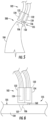
- the component 104 is an airfoil tip 200 with a known shape and size (e.g., a nozzle and/or blade).
- the component 104 can be a trailing edge and/or leading edge of the airfoil.
- the attachment mechanism 135 includes a plurality of grip arms 150 that attach the repair tool 102 onto the surface 105. The grip arms 150 are brought together onto the edge of the tip 200 until the repair tool 102 is secured onto the tip 200.
- three grip arms 150 are included in the attachment mechanism 135, although any suitable number of grip arms 150 may be utilized (e.g., three or more grip arms).
- the attachment mechanism 135 can be a suction cup attached onto the repair tool 102.
- the attachment mechanism 135 includes a suction cup 160 that attach the repair tool 102 onto the surface 105.
- a vacuum can be applied within the suction cup 160 to hold the repair tool 102 onto the surface in place.
- the suction cup 160 can be constructed of a deformable, air-impervious material (e.g., a rubber material) that can form a suction attachment with the surface 105.
- any number of suction cups can be utilized to secure the repair tool 102 onto the surface 105.
- an adhesive can be utilized to secure the repair tool 102 onto the surface 105, such as a hot melt adhesive, epoxy material, etc. Then, the adhesive material can be melted to remove the repair tool 102 from the surface 105.
- a working head 122 is positioned and secured adjacent to the identified defect 106 of the internal engine component(s) 104 being repaired (e.g., a turbine blade(s)).
- the defect 106 corresponds to a crack, void or other defective area formed along the exterior of the component 104 that defines an open or fillable volume 108 with a base 107 of the crack, void or other defective area.
- the working head 122 includes a work mechanism 124 configured for addressing the defect 106.
- the new material can be supplied from a location exterior to the engine to the internal location of the defect 106 to allow the fillable volume 108 defined by the defect 106 to be filled with the new material.
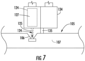
- Fig. 7 shows the repair tool 102 configured to supply high velocity powder particles 125 from the exterior of the engine into the fillable volume 108 of the defect 106.
- the high velocity particles 125 may plastically deform and adhere to the surface, thereby filling-in the fillable volume 108 and repairing the defect 106.
- the particles can impact the surface within the defect 106 at a speed of about 150 meters per second (m/s) to about 900 m/s.
- the average size of the powder particles 125 can vary depending on their composition, gun type, nozzle type, gases used, etc. In most embodiments, the particle size and distribution can be about 25 ⁇ m to about 150 ⁇ m (e.g., about 35 ⁇ m to about 75 ⁇ m (i.e., 400 to about 200 mesh)). In certain embodiments, no more than about five percent of the particles are larger than about 75 ⁇ m (200 mesh) and no more than about fifteen percent of the particles being smaller than about 35 ⁇ m (400 mesh).
- the powder particles 125 can be supplied to the location of the defect via the repair tool 102 such that the fillable volume 108 may be filled-in with the powder particles 125, thereby repairing the defect 106.
- the repair tool 102 is configured to supply the powder particles 125 within the interior of the gas turbine engine 10.
- the powder particles 125 may be transported via the repair tool 102 from a location exterior to the gas turbine engine 10 to a location within the engine 10 to allow the powder particles 125 to be injected or otherwise directed into the fillable volume 108 defined by the defect 106.
- the particles 125 may be supplied via a carrier fluid (e.g., a carrier gas) that is inert to the coating deposition.
- a carrier fluid e.g., a carrier gas
- the base 107 may be heated to a temperature of about 1000 °C to about 2000 °C (e.g., about 1800° C to about 2000° C), particularly with the component 104 is constructed from a metal alloy or super-alloy such as a nickel-based alloy, a chromium-based alloy, etc.
- a metal alloy or super-alloy such as a nickel-based alloy, a chromium-based alloy, etc.
- the repair tool 102 includes one or more heating elements (indicated by dashed lines 120) provided in operative association within the high temperature conduit 110.
- the repair tool 102 includes a high temperature conduit 110 for transporting the metal particles from outside the engine 10 to the location of the defect 106.
- the high temperature conduit 110 may extend lengthwise between working head 122 located within the gas turbine engine 10 and a material supply end 114 located exterior to the engine 10.
- the tip end of the tool 102 may generally be positioned adjacent to the location of the defect 106 for directing the particles 125 into the fillable volume 108.
- the material supply end 114 of the tool 102 may generally be configured to receive particles 125 from a particle source.
- particles 125 contained within a chamber (or other suitable powder particle source) located exterior to the gas turbine engine 10 may be supplied to the material supply end 114 of the tool 102.
- the particles 125 received at the material supply end 114 may then be directed through the high temperature conduit 110 to the tip end of the tool 102 to allow the metal particles to be delivered to the location of the defect 106.
- the heating element(s) 120 may be configured to generate heat within the high temperature conduit 110 as powder particles 125 is being supplied through the conduit 110 so as to allow for particle flow at the desired rate and speed.
- the heating element(s) 120 may correspond to a resisting heating element(s), such as one or more resistance wires, that is integrated into or incorporated within a wall(s) of the conduit 110.
- the heating element(s) 120 may correspond to any other suitable heat generating device(s) and/or component(s) that may be used to provide heating within the conduit 110 so as to maintain the temperature of the powder particles 125 at its desired delivery temperature.
- the particles 125 are delivered to the defect 106 at a temperature within 25% of its melting point (e.g., within 10% of its melting point).
- the powder particles 125 may be composed of any suitable metal material.
- the powder particles 125 may correspond to the parent metal material of the internal component 104 being repaired.
- the powder particles 125 may correspond to any other metal material that is suitable for use as a repair material within a gas turbine engine 10.
- the optical probe 130 corresponds to a separate component configured to be used in combination with the repair tool 102 for repairing the defect 106.
- the optical probe 130 may be coupled to or integrated within the repair tool 102.
- the optical probe 130 has been inserted through the same access port 62 as the repair tool 102.
- the probe 130 may be inserted into a different access port 62 than the repair tool 102, such as an access port 62 located adjacent to the access port 62 within which the repair tool 102 has been inserted.
- the optical probe 130 may correspond to any suitable optical device that allows images of the interior of the engine 10 to be captured or otherwise obtained.
- the optical probe 130 may correspond to a borescope, videoscope, fiberscope or any other similar optical device known in the art that allows for the interior of a gas turbine engine 10 to be viewed through an access port 62.
- the optical probe 130 may include one or more optical elements (indicated schematically by dashed box 132), such as one or more optical lenses, optical fibers, image capture devices, cables, and/or the like, for obtaining views or images of the interior of the engine 10 at a tip 134 of the probe 130 and for transmitting or relaying such images from the probe tip 134 along the length of the probe 130 to the exterior of the engine 10 for viewing by the personnel performing the repair procedure on the internal component(s) 104.
- the probe 130 may include a light source (indicated by dashed box 136) positioned at or adjacent to the probe tip 134 to provide lighting within the interior of the engine 10.
- the optical probe 130 may also include an articulation assembly 138 that allows the orientation of the probe tip 134 to be adjusted within the interior of the gas turbine engine 10.
- the articulation assembly 138 may allow for the probe tip 134 to be rotated or pivoted about a single axis or multiple axes to adjust the orientation of the tip 134 relative to the remainder of the probe 130.
- the articulation assembly 138 may generally have any suitable configuration and/or may include any suitable components that allow for adjustment of the orientation of the probe tip 134 relative to the remainder of the probe 130.
- a plurality of articulation cables 140 may be coupled between the probe tip 134 and one or more articulation motors 142. In such an embodiment, by adjusting the tension of the cables 140 via the motor(s) 142, the probe tip 134 may be reoriented within the gas turbine engine 10.
- the articulation assembly 138 also controls the attachment mechanism 135 so as to temporarily attach to the surface 105 the component 104 in order to perform the desired work thereon.
- Methods are generally provided for performing an in situ repair of an internal component of a gas turbine engine.
- the methods are discussed herein with reference to the gas turbine engine 10 and the system 100 described above with reference to FIGS. 1-8 .
- the disclosed methods may generally be implemented with gas turbine engines having any other suitable engine configuration and/or with systems having any other suitable system configuration.
- the methods are discussed in a particular order for purposes of discussion, the methods discussed herein are not limited to any particular order or arrangement.
- One skilled in the art using the disclosures provided herein, will appreciate that various steps of the methods disclosed herein can be omitted, rearranged, combined, and/or adapted in various ways without deviating from the scope of the present disclosure.
- the method may include inserting a repair tool through an access port of the gas turbine engine such that the tool includes a tip end positioned within the engine; positioning the tip adjacent to a defect (e.g., a crack or other distress point) within the surface of the component; and temporarily attaching the tip adjacent to the defect to allow precision work to be performed.
- the method may include positioning the tip end of the repair tool adjacent to a defect of an internal component of the gas turbine engine.
- the defect 106 may, for example, correspond to a crack, void or other defective area of an internal component 104 of the gas turbine engine 10.
- the method may include performing precision repair work (e.g., supplying powder particles, heating, etc.) using the repair tool by temporarily attaching the tip end of the repair tool to the surface of the component.
- precision repair work e.g., supplying powder particles, heating, etc.
Landscapes
- Engineering & Computer Science (AREA)
- Physics & Mathematics (AREA)
- Optics & Photonics (AREA)
- Mechanical Engineering (AREA)
- Plasma & Fusion (AREA)
- General Engineering & Computer Science (AREA)
- Robotics (AREA)
- Structures Of Non-Positive Displacement Pumps (AREA)
Claims (9)
- Verfahren zum Stoppen eines Risses (106) in einer Komponente (104) eines Gasturbinentriebwerks (10) zum Durchführen einer Reparatur vor Ort, wobei das Verfahren aus der Ferne ausgeführt wird und die Schritte umfasst:Einführen einer integrierten Reparaturschnittstelle, die an einem Kabelabgabesystem befestigt ist, wobei das Kabelabgabesystem eine Hochtemperaturleitung (110), die konfigurierbar ist, um Partikel dahindurch, innerhalb eines Gasturbinentriebwerks (10), abzugeben, umfasst, wobei die integrierte Reparaturschnittstelle ein Reparaturwerkzeug (102) umfasst, das Reparaturwerkzeug umfassend eine Spitze;Positionieren der Spitze angrenzend an einen Defekt (106) innerhalb einer Oberfläche (105) der Komponente (104);vorübergehendes Befestigen der Spitze angrenzend an den Defekt (106) innerhalb der Oberfläche (105) auf der Komponente (104);Erhitzen der Hochtemperaturleitung (110) mit einem Heizelement (120);Zuführen der Hochtemperaturleitung (110) eines neuen Materials (125) von außerhalb des Triebwerks (10), wobei das neue Material (125) ein Partikelpulver, umfassend eine Vielzahl von festen Partikeln (125), ist;Halten des neuen Materials (125) in der Hochtemperaturleitung (110) auf einer Abgabetemperatur innerhalb von 25 % des Schmelzpunkts des neuen Materials (125);Zuführen des neuen Materials (125) in den Defekt (106) bei der Abgabetemperatur, um den Defekt (106) zu füllen; undErhitzen mindestens des neuen Materials (125), um das neue Material (125) mit der Komponente (104) innerhalb des Defekts (106) zu verschmelzen.
- Verfahren nach Anspruch 1, wobei das neue Material (125) mit einer Geschwindigkeit von 150 m/s bis 900 m/s zugeführt wird.
- Verfahren nach Anspruch 1 oder 2, wobei das neue Material (125) mit einer durchschnittlichen Partikelgröße (125) von 25 µm bis 150 µm, vorzugsweise mit einer durchschnittlichen Partikelgröße von 35 µm bis 75 µm, in den Defekt (106) zugeführt wird.
- Verfahren nach Anspruch 1, wobei das neue Material (125) bei einer Temperatur innerhalb von etwa 10 % seines Schmelzpunkts in den Defekt (106) zugeführt wird.
- Verfahren nach Anspruch 1, wobei die Leitung (110) vorzugsweise aus einem keramischen Material ausgebildet ist, wobei sie sich der Länge nach zwischen dem Materialzufuhrende des Reparaturwerkzeugs und dem Spitzenende des Reparaturwerkzeugs erstreckt.
- Verfahren nach einem der vorstehenden Ansprüche, insbesondere durch Einführen des Reparaturwerkzeugs durch eine Zugangsöffnung (62) des Gasturbinentriebwerks, wobei, insbesondere, die Zugangsöffnung durch Gehäuse und/oder einen Rahmen des Gasturbinentriebwerks zum Bereitstellen eines Zugangs zu einem Inneren eines Kerntriebwerks (14) des Gasturbinentriebwerks definiert ist.
- Verfahren nach einem der vorstehenden Ansprüche, ferner umfassend:
Einführen einer optischen Sonde (130) durch eine Zugangsöffnung (62) oder eine angrenzende Zugangsöffnung (62) des Gasturbinentriebwerks (10), wobei die optische Sonde (130) konfiguriert ist, um eine Ansicht des Defekts (106) innerhalb des Gasturbinentriebwerks (10) bereitzustellen. - Verfahren nach Anspruch 7, wobei das Positionieren des Spitzenendes des Reparaturwerkzeugs angrenzend an den Defekt das Positionieren der Spitze relativ zu dem Defekt basierend auf der Ansicht, die durch die optische Sonde bereitgestellt wird, umfasst.
- Verfahren nach einem der vorstehenden Ansprüche, wobei die Spitze unter Verwendung eines Stativgriffs, eines Klebers oder eines Vakuumsaugers befestigt wird.
Applications Claiming Priority (1)
| Application Number | Priority Date | Filing Date | Title |
|---|---|---|---|
| US15/014,075 US10247002B2 (en) | 2016-02-03 | 2016-02-03 | In situ gas turbine prevention of crack growth progression |
Publications (2)
| Publication Number | Publication Date |
|---|---|
| EP3203017A1 EP3203017A1 (de) | 2017-08-09 |
| EP3203017B1 true EP3203017B1 (de) | 2024-10-16 |
Family
ID=57944330
Family Applications (1)
| Application Number | Title | Priority Date | Filing Date |
|---|---|---|---|
| EP17153875.4A Active EP3203017B1 (de) | 2016-02-03 | 2017-01-31 | Verfahren zum aufhalten eines risses in einer gasturbinentriebwerkskomponente zur durchführung von in-situ-reparaturen |
Country Status (5)
| Country | Link |
|---|---|
| US (1) | US10247002B2 (de) |
| EP (1) | EP3203017B1 (de) |
| CN (1) | CN107030445B (de) |
| CA (1) | CA2956352C (de) |
| SG (1) | SG10201700345UA (de) |
Families Citing this family (5)
| Publication number | Priority date | Publication date | Assignee | Title |
|---|---|---|---|---|
| US10094221B2 (en) * | 2016-02-03 | 2018-10-09 | General Electric Company | In situ gas turbine prevention of crack growth progression |
| US10443385B2 (en) * | 2016-02-03 | 2019-10-15 | General Electric Company | In situ gas turbine prevention of crack growth progression via laser welding |
| US10544676B2 (en) * | 2016-02-03 | 2020-01-28 | General Electric Company | Situ gas turbine prevention of crack growth progression |
| US10670538B2 (en) | 2018-04-30 | 2020-06-02 | General Electric Company | Techniques for control of non-destructive testing devices via a probe driver |
| US11548102B2 (en) * | 2020-07-31 | 2023-01-10 | General Electric Company | Method for repairing composite components using a plug |
Citations (2)
| Publication number | Priority date | Publication date | Assignee | Title |
|---|---|---|---|---|
| US20130167375A1 (en) * | 2011-11-18 | 2013-07-04 | Mtu Aero Engines Gmbh | Apparatus and method for processing a sealing element located within the housing of a gas turbine |
| US20130289766A1 (en) * | 2010-01-19 | 2013-10-31 | The Boeing Company | Apparatus for Automated Maintenance of Aircraft Structural Elements |
Family Cites Families (70)
| Publication number | Priority date | Publication date | Assignee | Title |
|---|---|---|---|---|
| US2011484A (en) | 1934-09-04 | 1935-08-13 | Hal W Harman | Method for repairing castings |
| US2252986A (en) | 1939-03-03 | 1941-08-19 | Lawrence B Scott | Method of repairing cracked or fractured metal walls |
| US2361106A (en) | 1940-11-04 | 1944-10-24 | Charles A Jensen | Method of repairing and for preventing cracks in metal castings |
| US4611744A (en) | 1982-06-23 | 1986-09-16 | Refurbished Turbine Components Ltd. | Turbine blade repair |
| US4743733A (en) | 1984-10-01 | 1988-05-10 | General Electric Company | Method and apparatus for repairing metal in an article |
| DE3813157A1 (de) | 1987-05-27 | 1988-12-15 | Bbc Brown Boveri & Cie | Verfahren zum verbinden und/oder instandstellen von bauteilen aus einer oxyddispersionsgehaerteten nickelbasis-superlegierung im zonengegluehten zustand grobkoerniger, laengsgerichteter stengelkristalle |
| US4869936A (en) * | 1987-12-28 | 1989-09-26 | Amoco Corporation | Apparatus and process for producing high density thermal spray coatings |
| JP2739600B2 (ja) * | 1989-10-03 | 1998-04-15 | 富士写真フイルム株式会社 | 強磁性金属粉末の処理方法及び磁気記録媒体の製造方法 |
| US5076660A (en) | 1990-01-26 | 1991-12-31 | Olympus Corporation | Light source receptacle for fiberoptic illumination |
| WO1991019016A1 (fr) * | 1990-05-19 | 1991-12-12 | Institut Teoreticheskoi I Prikladnoi Mekhaniki Sibirskogo Otdelenia Akademii Nauk Sssr | Procede et dispositif de revetement |
| US6270603B1 (en) | 1991-04-09 | 2001-08-07 | The Boeing Company | Repair method for uniformly heating composite structure |
| US5741965A (en) | 1996-11-29 | 1998-04-21 | Hernandez; Carlos M. | Aircraft jet engine testing tool |
| FR2763882B1 (fr) | 1997-05-29 | 1999-08-20 | Aerospatiale | Outillage de reparation sur site d'une structure composite presentant une zone endommagee et procede correspondant |
| GB9816421D0 (en) * | 1998-07-28 | 1998-09-23 | Keymed Medicals & Ind Equip | Apparatus for delivering laser energy to a remote location |
| US6269540B1 (en) | 1998-10-05 | 2001-08-07 | National Research Council Of Canada | Process for manufacturing or repairing turbine engine or compressor components |
| US6283356B1 (en) | 1999-05-28 | 2001-09-04 | General Electric Company | Repair of a recess in an article surface |
| US6464128B1 (en) | 1999-05-28 | 2002-10-15 | General Electric Company | Braze repair of a gas turbine engine stationary shroud |
| US6302625B1 (en) | 1999-10-15 | 2001-10-16 | United Technologies Corporation | Method and apparatus for refurbishing a gas turbine airfoil |
| GB0020461D0 (en) | 2000-08-18 | 2000-10-11 | Oliver Crispin Consulting Ltd | Improvements in and relating to the robotic positioning of a work tool to a sensor |
| US6414458B1 (en) | 2000-12-19 | 2002-07-02 | General Electric Company | Apparatus for robotically inspecting gas turbine combustion components |
| US6620457B2 (en) | 2001-07-13 | 2003-09-16 | General Electric Company | Method for thermal barrier coating and a liner made using said method |
| JP2003154483A (ja) | 2001-11-19 | 2003-05-27 | Mitsubishi Heavy Ind Ltd | 亀裂自動補修方法及びその装置 |
| US6593540B1 (en) | 2002-02-08 | 2003-07-15 | Honeywell International, Inc. | Hand held powder-fed laser fusion welding torch |
| US7392713B2 (en) | 2002-09-30 | 2008-07-01 | United Technologies Corporation | Monitoring system for turbomachinery |
| US7174797B2 (en) | 2002-10-15 | 2007-02-13 | Florida Turbine Technologies, Inc. | High temperature and pressure testing facility |
| US7032279B2 (en) | 2002-10-18 | 2006-04-25 | General Electric Company | Apparatus and methods for repairing compressor airfoils in situ |
| US6912446B2 (en) | 2002-10-23 | 2005-06-28 | General Electric Company | Systems and methods for automated sensing and machining for repairing airfoils of blades |
| US7000303B2 (en) | 2002-10-24 | 2006-02-21 | The Boeing Company | Method of repairing a crack in a component utilizing friction stir welding |
| DE10316966A1 (de) | 2003-04-12 | 2004-10-28 | Rolls-Royce Deutschland Ltd & Co Kg | Verfahren zum Wiederaufbauen flächig ausgebildeter beschädigter Bauteile |
| FR2854198B1 (fr) | 2003-04-22 | 2005-06-24 | Snecma Services | Procede pour remplacer un abradable sur le carter de soufflante d'un turboreacteur |
| US7016035B2 (en) | 2003-09-25 | 2006-03-21 | General Electric Company | Fiber optical apparatus and system for in situ laser plasma spectroscopy |
| US7038162B2 (en) | 2003-11-13 | 2006-05-02 | Honeywell International, Inc. | Hand-held laser welding wand filler media delivery systems and methods |
| JP4551082B2 (ja) | 2003-11-21 | 2010-09-22 | 三菱重工業株式会社 | 溶接方法 |
| US7034262B2 (en) | 2004-03-23 | 2006-04-25 | General Electric Company | Apparatus and methods for repairing tenons on turbine buckets |
| US7140240B2 (en) | 2004-06-21 | 2006-11-28 | Hamilton Sundstrand | Electric engine start system with inspection mode |
| US20060042083A1 (en) | 2004-08-27 | 2006-03-02 | Baker Martin C | Repair of turbines on wing |
| US7458768B2 (en) | 2005-06-28 | 2008-12-02 | United Technologies Corporation | Borescope inspection port device for gas turbine engine and gas turbine engine using same |
| US7513024B2 (en) | 2005-08-24 | 2009-04-07 | General Electric Company | Method for repairing structural cracks |
| US7499772B2 (en) | 2005-08-31 | 2009-03-03 | Honeywell International Inc. | Method and system for navigating a nondestructive evaluation device |
| JP4869699B2 (ja) | 2005-12-13 | 2012-02-08 | オリンパス株式会社 | 内視鏡装置 |
| GB0705696D0 (en) | 2007-03-24 | 2007-05-02 | Rolls Royce Plc | A method of repairing a damaged abradable coating |
| DE102007029728A1 (de) | 2007-06-27 | 2009-01-08 | Rolls-Royce Deutschland Ltd & Co Kg | Verfahren und Vorrichtung zur Reparatur von Blisks von Gasturbinen |
| US20090057275A1 (en) | 2007-08-31 | 2009-03-05 | General Electric Company | Method of Repairing Nickel-Based Alloy Articles |
| GB0808432D0 (en) | 2008-05-12 | 2008-06-18 | Rolls Royce Plc | An inspection arrangement |
| US8181528B2 (en) | 2009-02-27 | 2012-05-22 | General Electric Company | Method and system for ultrasonic inspection of gearbox ring gear |
| US9046892B2 (en) | 2009-06-05 | 2015-06-02 | The Boeing Company | Supervision and control of heterogeneous autonomous operations |
| GB2474834B (en) | 2009-10-28 | 2013-09-11 | Rolls Royce Plc | A method of inspecting and/or repairing component and a device for inspecting and/or repairing a component |
| US7866532B1 (en) | 2010-04-06 | 2011-01-11 | United Launch Alliance, Llc | Friction stir welding apparatus, system and method |
| JP5618643B2 (ja) | 2010-06-14 | 2014-11-05 | 株式会社東芝 | ガスタービン動翼の補修方法およびガスタービン動翼 |
| DE102010045869A1 (de) | 2010-08-03 | 2012-02-23 | Mtu Aero Engines Gmbh | Reinigung einer Turbomaschinenstufe |
| US8904635B2 (en) | 2010-11-04 | 2014-12-09 | General Electric Company | Method for servicing a turbine part |
| US8927897B2 (en) | 2010-11-17 | 2015-01-06 | Rolls-Royce Corporation | Laser maintenance tool |
| GB2504612B (en) * | 2011-05-09 | 2014-09-24 | Rolls Royce Plc | An apparatus for supporting a tool in an assembled apparatus |
| CN103635273A (zh) * | 2011-05-18 | 2014-03-12 | 东北泰克诺亚奇股份有限公司 | 金属粉末的制造方法及金属粉末的制造装置 |
| GB201113083D0 (en) | 2011-07-29 | 2011-09-14 | Formatex Offshore S A L | A method for in-situ cleaning of compressor blades in a gas turbine engine on aircraft and compositions |
| US8895887B2 (en) | 2011-08-05 | 2014-11-25 | General Electric Company | Resistance weld repairing of casing flange holes |
| DE102011122549A1 (de) | 2011-12-28 | 2013-07-04 | Rolls-Royce Deutschland Ltd & Co Kg | Verfahren zur Reparatur einer Einlaufschicht eines Verdichters einer Gasturbine |
| US8786300B2 (en) | 2012-02-07 | 2014-07-22 | General Electric Company | Probe assembly and methods for use in inspecting a component |
| US8801502B2 (en) | 2012-02-28 | 2014-08-12 | General Electric Company | In-situ airfoil contouring tool |
| US20140063228A1 (en) | 2012-09-06 | 2014-03-06 | General Electric Company | Method and system for cleaning surfaces and non-destructive inspection thereof |
| GB201216703D0 (en) | 2012-09-19 | 2012-10-31 | Rolls Royce Plc | A boroscope and a method of laser processing a component within an assembled apparatus using a boroscope |
| US9003880B2 (en) | 2012-12-31 | 2015-04-14 | General Electric Company | Reference speed measurement for a non-destructive testing system |
| GB2510816B (en) | 2013-02-12 | 2015-04-08 | Rolls Royce Plc | Material removal method |
| US9470658B2 (en) | 2013-03-12 | 2016-10-18 | The Boeing Company | Self-contained holonomic tracking method and apparatus for non-destructive inspection |
| JP6180221B2 (ja) | 2013-08-01 | 2017-08-16 | オリンパス株式会社 | ブレード検査装置 |
| US20150034266A1 (en) | 2013-08-01 | 2015-02-05 | Siemens Energy, Inc. | Building and repair of hollow components |
| JP6223049B2 (ja) | 2013-08-01 | 2017-11-01 | オリンパス株式会社 | ブレード検査システム |
| US10022921B2 (en) | 2013-12-19 | 2018-07-17 | General Electric Company | Turbine component patch delivery systems and methods |
| US10094221B2 (en) * | 2016-02-03 | 2018-10-09 | General Electric Company | In situ gas turbine prevention of crack growth progression |
| US20170218762A1 (en) * | 2016-02-03 | 2017-08-03 | General Electric Company | Situ Gas Turbine Prevention of Crack Growth Progression |
-
2016
- 2016-02-03 US US15/014,075 patent/US10247002B2/en active Active
-
2017
- 2017-01-16 SG SG10201700345UA patent/SG10201700345UA/en unknown
- 2017-01-25 CN CN201710056207.4A patent/CN107030445B/zh active Active
- 2017-01-26 CA CA2956352A patent/CA2956352C/en not_active Expired - Fee Related
- 2017-01-31 EP EP17153875.4A patent/EP3203017B1/de active Active
Patent Citations (2)
| Publication number | Priority date | Publication date | Assignee | Title |
|---|---|---|---|---|
| US20130289766A1 (en) * | 2010-01-19 | 2013-10-31 | The Boeing Company | Apparatus for Automated Maintenance of Aircraft Structural Elements |
| US20130167375A1 (en) * | 2011-11-18 | 2013-07-04 | Mtu Aero Engines Gmbh | Apparatus and method for processing a sealing element located within the housing of a gas turbine |
Also Published As
| Publication number | Publication date |
|---|---|
| CN107030445B (zh) | 2019-11-08 |
| SG10201700345UA (en) | 2017-09-28 |
| US10247002B2 (en) | 2019-04-02 |
| CN107030445A (zh) | 2017-08-11 |
| US20170218761A1 (en) | 2017-08-03 |
| CA2956352C (en) | 2019-12-31 |
| CA2956352A1 (en) | 2017-08-03 |
| EP3203017A1 (de) | 2017-08-09 |
Similar Documents
| Publication | Publication Date | Title |
|---|---|---|
| EP3202526B1 (de) | Reparaturmethode von rissen in elementen von gasturbinen | |
| EP3176365B1 (de) | System und verfahren zur durchführung einer in-situ-reparatur einer internen komponente eines gasturbinenmotors | |
| US11225869B2 (en) | In situ gas turbine prevention of crack growth progression | |
| EP3231993B1 (de) | Verfahren zur in-situ-auswuchtung eines rotierenden bauteils eines gasturbinentriebwerks | |
| EP3203017B1 (de) | Verfahren zum aufhalten eines risses in einer gasturbinentriebwerkskomponente zur durchführung von in-situ-reparaturen | |
| CN107214470A (zh) | 用于翼上修复的燃气涡轮机现场可膨胀囊 | |
| EP3203019B1 (de) | Verfahren zum anfügen von material an einem oberflächenbereich einer gasturbinentriebwerkskomponente | |
| CN107214469A (zh) | 用于在翼修理的燃气涡轮机原位可充胀囊 | |
| EP3203018B1 (de) | Verfahren zum aufhalten aus entfernung eines risses in einer gasturbinentriebwerkskomponente | |
| CA2957264A1 (en) | In situ gas turbine prevention of crack growth progression |
Legal Events
| Date | Code | Title | Description |
|---|---|---|---|
| PUAI | Public reference made under article 153(3) epc to a published international application that has entered the european phase |
Free format text: ORIGINAL CODE: 0009012 |
|
| STAA | Information on the status of an ep patent application or granted ep patent |
Free format text: STATUS: THE APPLICATION HAS BEEN PUBLISHED |
|
| AK | Designated contracting states |
Kind code of ref document: A1 Designated state(s): AL AT BE BG CH CY CZ DE DK EE ES FI FR GB GR HR HU IE IS IT LI LT LU LV MC MK MT NL NO PL PT RO RS SE SI SK SM TR |
|
| AX | Request for extension of the european patent |
Extension state: BA ME |
|
| STAA | Information on the status of an ep patent application or granted ep patent |
Free format text: STATUS: REQUEST FOR EXAMINATION WAS MADE |
|
| 17P | Request for examination filed |
Effective date: 20180209 |
|
| RBV | Designated contracting states (corrected) |
Designated state(s): AL AT BE BG CH CY CZ DE DK EE ES FI FR GB GR HR HU IE IS IT LI LT LU LV MC MK MT NL NO PL PT RO RS SE SI SK SM TR |
|
| STAA | Information on the status of an ep patent application or granted ep patent |
Free format text: STATUS: EXAMINATION IS IN PROGRESS |
|
| 17Q | First examination report despatched |
Effective date: 20180524 |
|
| GRAP | Despatch of communication of intention to grant a patent |
Free format text: ORIGINAL CODE: EPIDOSNIGR1 |
|
| STAA | Information on the status of an ep patent application or granted ep patent |
Free format text: STATUS: GRANT OF PATENT IS INTENDED |
|
| INTG | Intention to grant announced |
Effective date: 20240611 |
|
| GRAS | Grant fee paid |
Free format text: ORIGINAL CODE: EPIDOSNIGR3 |
|
| GRAA | (expected) grant |
Free format text: ORIGINAL CODE: 0009210 |
|
| STAA | Information on the status of an ep patent application or granted ep patent |
Free format text: STATUS: THE PATENT HAS BEEN GRANTED |
|
| AK | Designated contracting states |
Kind code of ref document: B1 Designated state(s): AL AT BE BG CH CY CZ DE DK EE ES FI FR GB GR HR HU IE IS IT LI LT LU LV MC MK MT NL NO PL PT RO RS SE SI SK SM TR |
|
| P01 | Opt-out of the competence of the unified patent court (upc) registered |
Free format text: CASE NUMBER: APP_51250/2024 Effective date: 20240910 |
|
| REG | Reference to a national code |
Ref country code: GB Ref legal event code: FG4D |
|
| REG | Reference to a national code |
Ref country code: CH Ref legal event code: EP Ref country code: DE Ref legal event code: R096 Ref document number: 602017085498 Country of ref document: DE |
|
| REG | Reference to a national code |
Ref country code: IE Ref legal event code: FG4D |
|
| REG | Reference to a national code |
Ref country code: LT Ref legal event code: MG9D |
|
| REG | Reference to a national code |
Ref country code: NL Ref legal event code: MP Effective date: 20241016 |
|
| REG | Reference to a national code |
Ref country code: AT Ref legal event code: MK05 Ref document number: 1733056 Country of ref document: AT Kind code of ref document: T Effective date: 20241016 |
|
| PG25 | Lapsed in a contracting state [announced via postgrant information from national office to epo] |
Ref country code: NL Free format text: LAPSE BECAUSE OF FAILURE TO SUBMIT A TRANSLATION OF THE DESCRIPTION OR TO PAY THE FEE WITHIN THE PRESCRIBED TIME-LIMIT Effective date: 20241016 |
|
| PG25 | Lapsed in a contracting state [announced via postgrant information from national office to epo] |
Ref country code: NL Free format text: LAPSE BECAUSE OF FAILURE TO SUBMIT A TRANSLATION OF THE DESCRIPTION OR TO PAY THE FEE WITHIN THE PRESCRIBED TIME-LIMIT Effective date: 20241016 |
|
| PG25 | Lapsed in a contracting state [announced via postgrant information from national office to epo] |
Ref country code: IS Free format text: LAPSE BECAUSE OF FAILURE TO SUBMIT A TRANSLATION OF THE DESCRIPTION OR TO PAY THE FEE WITHIN THE PRESCRIBED TIME-LIMIT Effective date: 20250216 Ref country code: HR Free format text: LAPSE BECAUSE OF FAILURE TO SUBMIT A TRANSLATION OF THE DESCRIPTION OR TO PAY THE FEE WITHIN THE PRESCRIBED TIME-LIMIT Effective date: 20241016 Ref country code: PT Free format text: LAPSE BECAUSE OF FAILURE TO SUBMIT A TRANSLATION OF THE DESCRIPTION OR TO PAY THE FEE WITHIN THE PRESCRIBED TIME-LIMIT Effective date: 20250217 |
|
| PG25 | Lapsed in a contracting state [announced via postgrant information from national office to epo] |
Ref country code: FI Free format text: LAPSE BECAUSE OF FAILURE TO SUBMIT A TRANSLATION OF THE DESCRIPTION OR TO PAY THE FEE WITHIN THE PRESCRIBED TIME-LIMIT Effective date: 20241016 |
|
| PG25 | Lapsed in a contracting state [announced via postgrant information from national office to epo] |
Ref country code: BG Free format text: LAPSE BECAUSE OF FAILURE TO SUBMIT A TRANSLATION OF THE DESCRIPTION OR TO PAY THE FEE WITHIN THE PRESCRIBED TIME-LIMIT Effective date: 20241016 |
|
| PG25 | Lapsed in a contracting state [announced via postgrant information from national office to epo] |
Ref country code: ES Free format text: LAPSE BECAUSE OF FAILURE TO SUBMIT A TRANSLATION OF THE DESCRIPTION OR TO PAY THE FEE WITHIN THE PRESCRIBED TIME-LIMIT Effective date: 20241016 |
|
| PG25 | Lapsed in a contracting state [announced via postgrant information from national office to epo] |
Ref country code: NO Free format text: LAPSE BECAUSE OF FAILURE TO SUBMIT A TRANSLATION OF THE DESCRIPTION OR TO PAY THE FEE WITHIN THE PRESCRIBED TIME-LIMIT Effective date: 20250116 |
|
| PG25 | Lapsed in a contracting state [announced via postgrant information from national office to epo] |
Ref country code: GR Free format text: LAPSE BECAUSE OF FAILURE TO SUBMIT A TRANSLATION OF THE DESCRIPTION OR TO PAY THE FEE WITHIN THE PRESCRIBED TIME-LIMIT Effective date: 20250117 Ref country code: AT Free format text: LAPSE BECAUSE OF FAILURE TO SUBMIT A TRANSLATION OF THE DESCRIPTION OR TO PAY THE FEE WITHIN THE PRESCRIBED TIME-LIMIT Effective date: 20241016 Ref country code: LV Free format text: LAPSE BECAUSE OF FAILURE TO SUBMIT A TRANSLATION OF THE DESCRIPTION OR TO PAY THE FEE WITHIN THE PRESCRIBED TIME-LIMIT Effective date: 20241016 |
|
| PG25 | Lapsed in a contracting state [announced via postgrant information from national office to epo] |
Ref country code: PL Free format text: LAPSE BECAUSE OF FAILURE TO SUBMIT A TRANSLATION OF THE DESCRIPTION OR TO PAY THE FEE WITHIN THE PRESCRIBED TIME-LIMIT Effective date: 20241016 |
|
| PG25 | Lapsed in a contracting state [announced via postgrant information from national office to epo] |
Ref country code: RS Free format text: LAPSE BECAUSE OF FAILURE TO SUBMIT A TRANSLATION OF THE DESCRIPTION OR TO PAY THE FEE WITHIN THE PRESCRIBED TIME-LIMIT Effective date: 20250116 |
|
| PG25 | Lapsed in a contracting state [announced via postgrant information from national office to epo] |
Ref country code: SM Free format text: LAPSE BECAUSE OF FAILURE TO SUBMIT A TRANSLATION OF THE DESCRIPTION OR TO PAY THE FEE WITHIN THE PRESCRIBED TIME-LIMIT Effective date: 20241016 |
|
| PG25 | Lapsed in a contracting state [announced via postgrant information from national office to epo] |
Ref country code: DK Free format text: LAPSE BECAUSE OF FAILURE TO SUBMIT A TRANSLATION OF THE DESCRIPTION OR TO PAY THE FEE WITHIN THE PRESCRIBED TIME-LIMIT Effective date: 20241016 |
|
| REG | Reference to a national code |
Ref country code: DE Ref legal event code: R097 Ref document number: 602017085498 Country of ref document: DE |
|
| PG25 | Lapsed in a contracting state [announced via postgrant information from national office to epo] |
Ref country code: EE Free format text: LAPSE BECAUSE OF FAILURE TO SUBMIT A TRANSLATION OF THE DESCRIPTION OR TO PAY THE FEE WITHIN THE PRESCRIBED TIME-LIMIT Effective date: 20241016 |
|
| PG25 | Lapsed in a contracting state [announced via postgrant information from national office to epo] |
Ref country code: RO Free format text: LAPSE BECAUSE OF FAILURE TO SUBMIT A TRANSLATION OF THE DESCRIPTION OR TO PAY THE FEE WITHIN THE PRESCRIBED TIME-LIMIT Effective date: 20241016 |
|
| PG25 | Lapsed in a contracting state [announced via postgrant information from national office to epo] |
Ref country code: SK Free format text: LAPSE BECAUSE OF FAILURE TO SUBMIT A TRANSLATION OF THE DESCRIPTION OR TO PAY THE FEE WITHIN THE PRESCRIBED TIME-LIMIT Effective date: 20241016 |
|
| PG25 | Lapsed in a contracting state [announced via postgrant information from national office to epo] |
Ref country code: CZ Free format text: LAPSE BECAUSE OF FAILURE TO SUBMIT A TRANSLATION OF THE DESCRIPTION OR TO PAY THE FEE WITHIN THE PRESCRIBED TIME-LIMIT Effective date: 20241016 |
|
| PG25 | Lapsed in a contracting state [announced via postgrant information from national office to epo] |
Ref country code: IT Free format text: LAPSE BECAUSE OF FAILURE TO SUBMIT A TRANSLATION OF THE DESCRIPTION OR TO PAY THE FEE WITHIN THE PRESCRIBED TIME-LIMIT Effective date: 20241016 |
|
| PLBE | No opposition filed within time limit |
Free format text: ORIGINAL CODE: 0009261 |
|
| STAA | Information on the status of an ep patent application or granted ep patent |
Free format text: STATUS: NO OPPOSITION FILED WITHIN TIME LIMIT |
|
| REG | Reference to a national code |
Ref country code: CH Ref legal event code: PL |
|
| PG25 | Lapsed in a contracting state [announced via postgrant information from national office to epo] |
Ref country code: SE Free format text: LAPSE BECAUSE OF FAILURE TO SUBMIT A TRANSLATION OF THE DESCRIPTION OR TO PAY THE FEE WITHIN THE PRESCRIBED TIME-LIMIT Effective date: 20241016 |
|
| PG25 | Lapsed in a contracting state [announced via postgrant information from national office to epo] |
Ref country code: MC Free format text: LAPSE BECAUSE OF FAILURE TO SUBMIT A TRANSLATION OF THE DESCRIPTION OR TO PAY THE FEE WITHIN THE PRESCRIBED TIME-LIMIT Effective date: 20241016 Ref country code: LU Free format text: LAPSE BECAUSE OF NON-PAYMENT OF DUE FEES Effective date: 20250131 |
|
| 26N | No opposition filed |
Effective date: 20250717 |
|
| PG25 | Lapsed in a contracting state [announced via postgrant information from national office to epo] |
Ref country code: BE Free format text: LAPSE BECAUSE OF NON-PAYMENT OF DUE FEES Effective date: 20250131 |
|
| PG25 | Lapsed in a contracting state [announced via postgrant information from national office to epo] |
Ref country code: CH Free format text: LAPSE BECAUSE OF NON-PAYMENT OF DUE FEES Effective date: 20250131 |
|
| REG | Reference to a national code |
Ref country code: BE Ref legal event code: MM Effective date: 20250131 |
|
| PGFP | Annual fee paid to national office [announced via postgrant information from national office to epo] |
Ref country code: GB Payment date: 20251220 Year of fee payment: 10 |
|
| PGFP | Annual fee paid to national office [announced via postgrant information from national office to epo] |
Ref country code: FR Payment date: 20251217 Year of fee payment: 10 |
|
| PG25 | Lapsed in a contracting state [announced via postgrant information from national office to epo] |
Ref country code: IE Free format text: LAPSE BECAUSE OF NON-PAYMENT OF DUE FEES Effective date: 20250131 |
|
| PGFP | Annual fee paid to national office [announced via postgrant information from national office to epo] |
Ref country code: DE Payment date: 20251217 Year of fee payment: 10 |