EP3202989B1 - Vorrichtung zum öffnen und schliessen eines stöpsels einer ablaufgarnitur - Google Patents
Vorrichtung zum öffnen und schliessen eines stöpsels einer ablaufgarnitur Download PDFInfo
- Publication number
- EP3202989B1 EP3202989B1 EP16205746.7A EP16205746A EP3202989B1 EP 3202989 B1 EP3202989 B1 EP 3202989B1 EP 16205746 A EP16205746 A EP 16205746A EP 3202989 B1 EP3202989 B1 EP 3202989B1
- Authority
- EP
- European Patent Office
- Prior art keywords
- actuating member
- opening
- catches
- rotor
- actuating
- Prior art date
- Legal status (The legal status is an assumption and is not a legal conclusion. Google has not performed a legal analysis and makes no representation as to the accuracy of the status listed.)
- Active
Links
Images


Classifications
-
- E—FIXED CONSTRUCTIONS
- E03—WATER SUPPLY; SEWERAGE
- E03C—DOMESTIC PLUMBING INSTALLATIONS FOR FRESH WATER OR WASTE WATER; SINKS
- E03C1/00—Domestic plumbing installations for fresh water or waste water; Sinks
- E03C1/12—Plumbing installations for waste water; Basins or fountains connected thereto; Sinks
- E03C1/22—Outlet devices mounted in basins, baths, or sinks
- E03C1/23—Outlet devices mounted in basins, baths, or sinks with mechanical closure mechanisms
- E03C1/2306—Outlet devices mounted in basins, baths, or sinks with mechanical closure mechanisms the plug being operated by hand contact
-
- F—MECHANICAL ENGINEERING; LIGHTING; HEATING; WEAPONS; BLASTING
- F16—ENGINEERING ELEMENTS AND UNITS; GENERAL MEASURES FOR PRODUCING AND MAINTAINING EFFECTIVE FUNCTIONING OF MACHINES OR INSTALLATIONS; THERMAL INSULATION IN GENERAL
- F16K—VALVES; TAPS; COCKS; ACTUATING-FLOATS; DEVICES FOR VENTING OR AERATING
- F16K31/00—Actuating devices; Operating means; Releasing devices
- F16K31/44—Mechanical actuating means
- F16K31/56—Mechanical actuating means without stable intermediate position, e.g. with snap action
Definitions
- the present invention refers to an opening and closing device for sanitary fittings according to the preamble of claim 1.
- closing plugs for sanitary devices are used, such as for example for basins, sinks, receptors, bathtubs, which comprise a typically mushroom-shaped movable plug, which is coupled to a stationary drain, inserted into or anyway connected to a draining hole of the sanitary device.
- the devices for actuating closing plugs typically comprise lever mechanisms and/or transmissions for actuating them, particularly in order to pass from the lowered or closed condition, wherein the plug occludes the draining hole, to a raised or open condition, wherein the plug enables the water to flow down through the draining hole.
- lever mechanisms have the drawback of requiring a suitable calibration and adjustment; further, due to the corrosion, scales and mechanical clearances of the different components, such known mechanisms over time do not ensure an optimal operation of the plug; further, such mechanisms tend to get substantially unyielding over time, so that they are not easy to be actuated. Further such lever devices are often bulky and unattractive, since they have exposed components, for example in the basins, sinks, bidets, and bathtubs.
- snap-closing devices which avoid using lever mechanisms or transmissions.
- Such devices comprise a snap device wherein a movable part is fixed to the plug and a stationary part is connected to the drain.
- a snap-closing device is described in patent EP 1 338 707 B1 .
- a first disadvantage is due to the fact they are noisy: the snap mechanism emits a quite perceivable "click" when passing from the open configuration to the closed one and viceversa.
- the known devices are provided with rather stiff internal springs which, on one hand, always ensure to snappingly open/close them, however, on the other hand, beside increasing the cited actuating noise, they require a relatively high actuating force.
- the springs are oversized in order to enable to open the plug also in a maximum load condition, in other words when, after closing the plug and filled the container (a basin/sink or a bathtub), it is necessary to open the plug for draining the water. In such condition, it is necessary to overcome also the weight of the water column acting on the portion of the plug surface.
- EP1338707A1 is selected as representing the closest prior art for claim 1. The features mentioned in the preamble of claim 1 are disclosed in said document.
- 4 generally indicates an opening/closing device for sanitary fittings according to the present invention.
- an opening/closing device for sanitary fittings must be understood in a general way, in that it comprises, for example, devices for basins, sinks, receptors, bathtubs and similar.
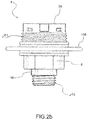
- the opening/closing device 4 for sanitary fittings comprises a body 8 associated or associable integrally to a closing plug 12. Moreover, the device 4 comprises a stem 16 preferably housed inside the body 8. The stem 16 is adapted to be stably and integrally coupled to a drain 18, in turn associated or associable to the sanitary fitting at the draining hole. The plug 12, according to the position thereof, is adapted to occlude the access to the drain 18, in order to prevent to drain the water from the sanitary fitting, or to leave unobstructed the access to the drain, enabling in this way to drain the water.
- device 4 can be associated to a valve or similar device, preferably, but not exclusively, for sanitary fittings. Therefore, the concept of the closing plug 12 must be considered in a general way, in that it comprises a device adapted to occlude an opening engaged by the drain 18. Also, the concept of a drain must be considered in a general term, in that is means an interface between the device 4 and opening that the device must be capable of selectively opening/occluding by said closing plug.
- the body 8 is connected to the closing plug 12 by a variety of means, for example by a threaded connection 13 (in this regard, see the exemplifying embodiment illustrated in Figures 1b or 2b ) or by snap-connecting means such as for example fins 14 (in this regard, see the exemplifying embodiment illustrated in Figures 1a and 2a ) or as an alternative, by gluing or similar solutions (not shown in the figures).
- the stem 16 can be associated to the drain 18 by a threaded connection 11 (according to the embodiments illustrated in the figures), by a snap connection or similar. Such last alternative variants are not illustrated in the figures.
- the drain 18, as it is known, can be associated to a hole of a sanitary device such as for example a basin, sink, receptor, bathtub and similar for regulating the opening/closure of said hole and therefore enabling both to fill and empty such sanitary devices.
- a sanitary device such as for example a basin, sink, receptor, bathtub and similar for regulating the opening/closure of said hole and therefore enabling both to fill and empty such sanitary devices.
- the body 8 is translatingly movable with respect to the stem 16 along an actuating axis X-X of the opening/closing device 4.
- the body 8, which, as said, preferably receives inside the stem 16, is for this reason advantageously hollow and comprises a lower opening 20, an upper opening 22, opposite to the lower opening 20 with reference to the direction determined by said actuating axis X-X. It is observed in the present invention and in the attached claims that the terms "lower” and “upper” refer to the normal conditions of use of the device 4 when is associated to a sanitary fitting.
- the stem 16 and body 8 are coupled to each other so that the body 8 can translate with respect to the stem 16 along the actuating axis X-X, however it cannot rotate with respect to the stem 16 about the axis X-X itself.
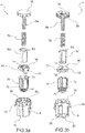
- the body 8 and stem 16 are connectable to each other by a prismatic coupling obtained, for example, by an engagement in at least one groove 24 associated to the body 8 of a respective rib 26 associated to the stem 16 (or viceversa), the groove 24 and rib 26 are both parallel to said actuating axis X-X (see Figures 3a and 3b , for example).
- the device 4 comprises a cover 28 associated to the body 8, for closing the upper opening 22 of this latter.
- the cover 28 is integral with the body 8 and, advantageously, forms by it an actuating member of the device 4, actuatable by an user, particularly by acting on the plug 12, for opening and closing the draining hole, as it will be explained in the following.
- the actuating member could be configured differently with respect to what has been described.
- the device 4 comprises an actuating spring 32, such as for example a coil spring adapted to exert an elastic action, parallel to said actuating axis X-X, on the actuating member, particularly on the cover 28 and consequently on the body 8 integral to it.
- the actuating spring 32 is disposed and configured for biasing the cover 28 away from the stem 16, in other words in the upper direction of the device 4.
- the device 4 comprises a rotor 36 rotating about said actuating axis X-X and provided with thrusting elements 40 having an upper outline 44, facing the cover 28, and a lower outline 48 opposite to the upper outline 44.
- the rotor 36 is capable of rotating about the actuating axis X-X with respect to the stem 16. As an alternative, it can be translatingly integral with the stem 16 or can freely axially translates with respect to it.
- the device 4 preferably comprises a rotor support 52, which can be for example disposed inside and coaxially to said rotor 36 and preferably fixed, again inside, to the stem 16. As an alternative, it is observed the rotor support 52 can axially slide with respect to the stem 16, in this way axial translations of the rotor 36 with respect to the stem 16 itself are possible.
- the actuating member comprises upper catches adapted to interact with the upper outline 44 of said thrusting elements 40 of the rotor 36, and lower catches adapted to interact with the lower outline 48 of said thrusting elements 40 of the rotor 36.
- the cover 28 comprises upper catches 56 adapted to interact with the lower outline 44 of said thrusting elements 40 of the rotor 36.
- the body 8 comprises, preferably inside, for example on an internal lateral wall 60, lower catches 64 adapted to interact with the lower outline 48 of said thrusting elements 40 of the rotor 36.
- such lower catches 64 are configured for enabling the lower outline 48 of the thrusting elements 40 of the rotor 36 to slide to a stop condition determined by an abutment formed by the lower catches 64 themselves for the thrusting elements 40 of the rotor 36 in the closed configuration of the closing plug 12.
- the body 8 preferably comprises, again on said internal lateral wall 60, recesses 68 alternate between the lower catches 64, disposed at a lower height along the actuating axis X-X with respect to said lower catches 64.
- recesses 68 are adapted to house the thrusting elements 50 of the rotor 36 in the extended configuration of the actuating member, preferably corresponding to an open configuration of the closing plug 12.
- the rotor 36 comprises a cylindrical disk provided, on an external lateral wall 72, with said thrusting elements 40.
- the thrusting elements 40 have a size and shape such to be capable of facing the lower catches 64 and stop recesses 68 of the body 8.
- the lower outlines 44 of the thrusting elements 40 are countershaped to the upper catches 56 of the cover 28, in order to locally obtain threaded-type couplings, so that relative movements between the rotor 36 and cover 28 similar to the ones of a screw and nut screw are possible.
- the lower outlines 44 of the thrusting elements 40 are shaped as helixes portions in order to define upper planes tangent to the helixes portion itself sloped with an oblique inclination angle ⁇ with respect to a median plane M-M normal to said actuating axis X-X ( Figure 8 ).
- the upper catches 56 of the cover 28 form upper abutments 76, alternate between two consecutive upper catches 56, adapted to obtain a stop to the reciprocal rotation between each thrusting element 40 and the cover 8 itself.
- the lower outlines 48 of the thrusting elements 40 are countershaped to the lower catches 64 of the body 8, in order to locally form threaded-type couplings. Particularly, they are shaped as helixes portions in order to define lower planes tangent to the helixes portion itself sloped with an oblique inclination angle ⁇ with respect to the median plane M-M normal to said actuating axis X-X ( Figure 8 ).
- the lower outlines 48 of the thrusting elements 40 are further countershaped also to the stop recesses 68 of the cover 28.
- such upper and lower planes exhibit inclination angles ⁇ , ⁇ , opposite to each other with respect to said median plane M-M normal to said actuating axis X-X, so that the thrusting elements 40 generally take a substantially triangular or trapezoidal configuration.
- the lower catches 64 of the body 8 form lower abutments 80, alternated between a lower catch 64 and a following recess 68, having lateral abutment surfaces 81 adapted to form a stop to the reciprocal rotation between each thrusting element 40 and the body 8 itself.
- the lower abutments stop the rotation of the rotor 36 about said actuating axis X-X.
- the cover 28 is disposed on the side of the upper opening 22 of the body 8 and is provided with the lower catches 56.
- the cover 28 is integral with a central pin 84, coaxial to the body 8, said central pin 84 being inserted inside said actuating spring 32 and inside said rotor support 52.
- the pin 84 can be integrally connected to the cover 28 or can be made in one piece with it.
- the rotor support 52 in an assembled condition of the device 4, abuts on a narrowing 88 of the stem 16, in which the rotor support 52 comprises a perimetral edge 92 axially constraining the rotor 36 between the rotor support 52 and stem 16, on which the rotor 36 abuts in correspondence of an upper surface 54 ( Figures 4a and 4b ).
- the rotor support 42 is configured so that between said perimetral edge 92 and rotor 36, there is an axial clearance 96, when the rotor support 52 abuts on said narrowing 88 of the stem 16.
- the body 8 is integrally associated to the closing plug 12
- the stem 16 is integrally associated to the drain 18, adapted to be occluded by said closing plug 12.
- the tight occlusion of the drain 18 is preferably obtained by providing a seal 108.
- said seal 108 is associated to the closing plug 12 and is disposed perimetrally to a lateral wall of said closing plug 12 so that can abut on the drain 18 and tightly close it ( Figure 1a ).
- a seal 108 adapted to tightly occlude the drain 18, in a closed configuration of the opening/closing device 4 and of the respective closing plug 12 ( Figure 1b ) is coaxially associated to the outside of the body 8.
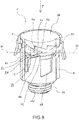
- the actuating spring 32 is substantially uncompressed (with the exception of the compression action exerted by the weight of the plug 12 and possibly of the residual water column) in order to take the body 8 and therefore the plug to a maximum distance condition from the stem 16 and drain 18, with respect to said actuating axis X-X (such condition is illustrated in Figure 5 , for example).
- the actuating spring 32 extends, in other words is disposed in an extracted configuration, and raises the closing plug 12 in order to avoid a contact between the seal 108 and drain 18 and to enable the water to flow down through the drain 18.
- the closed configuration of the plug is exemplifyingly considered as the retracted configuration of the actuating member and that the open configuration of the plug corresponds to the extended configuration of the actuating member.
- the extended configuration of the actuating member corresponds the closed configuration of the plug
- the retracted configuration of the actuating member corresponds the open configuration of the plug.
- Figure 7 shows, in such configuration, that there is no direct contact between the upper outlines 44 of the thrusting elements 40 and the upper catches 56 of the cover 28: particularly there is a clearance 112 between the upper outlines 44 of the thrusting elements 40 and the upper catches 56 of the cover 28.
- the plug 12 is pressed by a hand or a finger of a user, in order to pass from the closed configuration to the open one, the user is not required to overcome any friction force between the upper outlines 44 of the thrusting elements 40, and the upper catches 56 of the cover 28.
- the upper outlines 44 of the thrusting elements 40 contact the upper catches 56 of the cover 28: such contact causes a thrust determining a rotation of the rotor 36 about the actuating axis X-X.
- a further consequence of such rotation is a relative sliding between the upper outlines 44 and lower outlines 56.
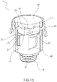
- the following step of closing the plug comprises the opposite steps. Particularly, by pressing the plug 12 (arrow F in Figure 13 ) the body 8 and cover 28 are again lowered, consequently the thrusting elements 40 of the rotor 36 disengage the recesses 68 of the body 8 until the lower outlines 44 of the thrusting elements 40 of the rotor 36 again engage the upper catches 56 of the cover 28 ( Figure 13 ).
- the opening/closing device requires an actuating force smaller than the one of the snap devices of the prior art.
- the device when the device is in a closed condition and must be opened, following a manual pressure on the plug, there is no starting friction on the thrusting elements of the rotor and on the upper catches of the cover.
- the spring must be sized for overcoming the weight of the plug and the water column acting on the mushroom portion of the plug, and not also the friction force among the reciprocally sliding parts of the mechanism, as in the prior art solutions.
- the opening/closing device according to the invention is quieter than the snap devices of the prior art. Actually, when the mechanism is actuated it is not perceived any "click".
- the actuating device of the present invention can be particularly appreciated by the users because is smooth and quite when is actuated.
- the smoothness and quietness are not a detriment to the reliability of the device which ensures an optimal operation also after years, despite the device operates in an adverse environment since is subjected to water, dirt and calcareous scales.
- the term reliability means that the device neither jams nor rigidifies when used; further in closed conditions, the mechanism always ensures a suitable tight sealing of the drain.
- the mechanism portion integral with the plug does not rotate when passing from the open condition to the closed one and viceversa: in this way attritions between the seal and the stationary part of the drain are prevented. Such attritions, over the time, would compromise the seal tightness and enable the water to leak also when the plug is closed.
- the plug shows a trademark, for example of a manufacturer
- the trademark can rotate when the plug is operated and therefore is prevented a misalignment of the same with the stationary part of the sanitary device.
Landscapes
- Engineering & Computer Science (AREA)
- General Engineering & Computer Science (AREA)
- Mechanical Engineering (AREA)
- Environmental & Geological Engineering (AREA)
- Health & Medical Sciences (AREA)
- Life Sciences & Earth Sciences (AREA)
- Hydrology & Water Resources (AREA)
- Public Health (AREA)
- Water Supply & Treatment (AREA)
- Sink And Installation For Waste Water (AREA)
Claims (14)
- Öffnungs- und Schließvorrichtung (4) für Sanitärarmaturen, umfassend:- ein Betätigungselement (8, 28), das einem Verschlussstopfen (12) einstückig zugeordnet werden kann;- einen Schaft (16), der einstückig mit einem Ablauf (18) verbindbar ist, der dazu ausgelegt ist, mit dem Stopfen (12) geschlossen zu werden, wobei das Betätigungselement (8, 28) in Bezug auf den Schaft (16) entlang einer Betätigungsachse (X-X) der Öffnungs- und Schließvorrichtung (4) zwischen einer ersten Gleichgewichtsposition, die einer zurückgezogenen Konfiguration des Betätigungselements entspricht, und einer zweiten Gleichgewichtsposition, die einer ausgefahrenen Konfiguration des Betätigungselements entspricht, per Durchgang durch eine Zwischenposition bewegbar ist;- eine Betätigungsfeder (32), die geeignet ist, das Betätigungselement (8, 28) in Richtung der zweiten Gleichgewichtsposition zu belasten;dadurch gekennzeichnet, dass die Zwischenposition einer Anschlagskonfiguration des Betätigungselements entspricht und dass die Öffnungs- und Schließvorrichtung (4) ferner umfasst:- einen Rotor (36), der um die Betätigungsachse (X-X) drehbar ist und Schubelemente (40) mit einer oberen Umrandung (44) und einer der oberen Umrandung (44) gegenüber angeordneten unteren Umrandung (48) aufweist,wobei gilt:
wobei das Betätigungselement (8, 28) obere Rasten (56) aufweist, die geeignet sind, mit der oberen Umrandung (44) der Schubelemente (40) des Rotors (36) zusammenzuwirken, und ferner untere Rasten (64) und Aussparungen (68) auf einer anderen Ebene als die unteren Rasten (64), die geeignet sind, mit der unteren Umrandung (48) der Schubelemente (40) des Rotors (36) zusammenzuwirken, um Schubkräfte zu erzeugen, die geeignet sind, den Rotor (36) aufgrund der Wechselwirkungen um die Betätigungsachse (X-X) zu drehen,- in der zurückgezogenen Konfiguration des Betätigungselements ist die untere Umrandung (48) des Schubelements (40) mit den unteren Rasten (64) des Betätigungselementes in Eingriff;- in der ausgefahrenen Konfiguration des Betätigungselements ist die untere Umrandung (48) der Schubelemente (40) mit den Aussparungen (68) des Betätigungselements in Eingriff;- in der Anschlagskonfiguration des Betätigungselements ist die obere Umrandung (44) des Schubelements (40) mit den oberen Rasten (56) des Betätigungselements in Eingriff. - Öffnungs- und Schließvorrichtung (4) nach Anspruch 1, wobei:- die untere Umrandung (48) der Schubelemente (40) beim Umschalten von der zurückgezogenen Konfiguration in die Anschlagskonfiguration des Betätigungselements die unteren Rasten (64) des Betätigungselements löst und die obere Umrandung (44) der Schubelemente (40) in die oberen Rasten (56) des Betätigungselements durch Gleiten entlang dieser infolge der Drehung des Rotors (36) eingreift;- die obere Umrandung (44) der Schubelemente (40) beim Umschalten von der Anschlagskonfiguration in die ausgefahrene Konfiguration des Betätigungselements die oberen Rasten (56) des Betätigungselements löst und die untere Umrandung (48) der Schubelemente (40) in die Aussparungen (68) des Betätigungselements eingreift, indem sie infolge der Drehung des Rotors (36) entlang der unteren Rasten (64) und/oder entlang der Aussparungen (68) gleitet;- die untere Umrandung (48) der Schubelemente (40) beim Umschalten von der ausgefahrenen Konfiguration in die Anschlagskonfiguration des Betätigungselements die Aussparungen (68) des Betätigungselements löst und die obere Umrandung (44) der Schubelemente (40) in die oberen Rasten (56) des Betätigungselements eingreift, indem sie infolge der Drehung des Rotors (36) entlang dieser gleitet;- die obere Umrandung (44) der Schubelemente (40) beim Umschalten von der Anschlagskonfiguration in die ausgefahrene Konfiguration des Betätigungselements die oberen Rasten (56) des Betätigungselements löst und die untere Umrandung (48) der Schubelemente (40) in die unteren Rasten (64) des Betätigungselements durch Gleiten entlang dieser infolge der Drehung des Rotors (36) eingreift.
- Öffnungs- und Schließvorrichtung (4) nach Anspruch 1 oder 2, wobei die zurückgezogene Konfiguration des Betätigungselements einer per Stopfen (12) geschlossenen Konfiguration entspricht, wobei der Stopfen (12) unter Betriebsbedingungen der Vorrichtung (4) den Ablauf (18) verschließt und die ausgefahrene Konfiguration des Betätigungselements einer Konfiguration mit geöffnetem Stopfen (12) entspricht, wobei der Stopfen (12) unter Betriebsbedingungen der Vorrichtung (4) den Ablauf (18) offen hält.
- Öffnungs- und Schließvorrichtung (4) nach einem der vorstehenden Ansprüche, wobei das Betätigungselement einen Körper (8) aufweist, der dem Verschlussstopfen (12) einstückig zugeordnet oder zuordenbar ist und entlang der Betätigungsachse (X-X) translatorisch verschiebbar ist, wobei der Körper (8) eine untere Öffnung (20) aufweist, die dem Schaft (16) zugewandt ist und von diesem gekreuzt wird, und eine obere Öffnung (22), die der unteren Öffnung (20) in Bezug auf die Betätigungsachse (X-X) gegenüberliegt, und eine Abdeckung (28), die der oberen Öffnung (22) des Körpers (8) schließend zugeordnet ist, wobei die oberen Rasten (56) der Abdeckung (28) und die unteren Rasten (64) und die Aussparungen (68) dem Körper (8) zugeordnet sind.
- Öffnungs- und Schließvorrichtung (4) nach einem der vorstehenden Ansprüche, umfassend einen Rotorträger (52), der mit dem Schaft (16) einstückig angeordnet oder entlang der Betätigungsachse (X-X) in Bezug auf diesen verschiebbar ist, wobei er innerhalb und koaxial mit dem Rotor (36) angeordnet und so geformt ist, dass er den Rotor (36) und den Schaft (16) um die Betätigungsachse (X-X) drehbar koppelt.
- Öffnungs- und Schließvorrichtung (4) nach einem der vorstehenden Ansprüche, wobei der Rotor (36) eine zylindrische Form aufweist und an einer seiner äußeren Seitenwände (72) mit den Schubelementen (40) versehen ist.
- Öffnungs- und Schließvorrichtung (4) nach einem der vorstehenden Ansprüche, wobei die oberen Umrandungen (44) der Schubelemente (40) zu den oberen Rasten (56) des Betätigungselements gegengeformt sind und als Abschnitte von Spiralen geformt sind, um obere Ebenen zu definieren, die tangential zu den Spiralenabschnitten verlaufen und in einem schrägen Neigungswinkel (α) in Bezug auf eine Mittelebene (M-M) senkrecht zu der Betätigungsachse (X-X) geneigt sind.
- Öffnungs- und Schließvorrichtung (4) nach einem der vorstehenden Ansprüche, wobei die oberen Rasten (56) des Betätigungselements obere Widerlager (76) aufweisen, die geeignet sind, eine reziproke Gleitbewegung zwischen den oberen Umrandungen (44) jedes Schubelements (40) und den oberen Rasten (56) selbst zu stoppen.
- Öffnungs- und Schließvorrichtung (4) nach einem der vorstehenden Ansprüche, wobei die unteren Umrandungen (48) der Schubelemente (40) zu den unteren Rasten (64) und Aussparungen (68) des Betätigungselements gegengeformt sind und als Abschnitte von Spiralen geformt sind, um untere Ebenen zu definieren, die tangential zu den Spiralenabschnitten verlaufen und in einem schrägen Neigungswinkel (β) in Bezug auf eine Mittelebene (M-M) senkrecht zu der Betätigungsachse (X-X) geneigt sind.
- Öffnungs- und Schließvorrichtung (4) nach den Ansprüchen 7 und 9, wobei die obere und die untere Ebene einander gegenüberliegende Neigungswinkel (α, β) mit Bezug auf die Mittelebene (M-M) senkrecht zu der Betätigungsachse (X-X) bilden, so dass die Schubelemente (40) im Allgemeinen eine im Wesentlichen dreieckige oder trapezförmige Konfiguration annehmen.
- Öffnungs- und Schließvorrichtung (4) nach einem der vorstehenden Ansprüche, wobei die unteren Rasten (64) des Betätigungselements untere Widerlager (80) aufweisen, wobei jedes untere Widerlager zwischen einer unteren Raste (64) und einer nachfolgenden Aussparung (68) angeordnet ist und seitliche Widerlagerflächen (81) aufweist, die geeignet sind, eine Anhaltung der reziproken Gleitbewegung zwischen den unteren Umrandungen (48) jedes Schubelements (40) und den unteren Rasten (64) selbst auszuführen.
- Öffnungs- und Schließvorrichtung (4) nach einem der vorstehenden Ansprüche in Abhängigkeit von den Ansprüchen 4 und 5, wobei die Abdeckung (28) einem zentralen Stift (84) koaxial zum Körper (8) einstückig zugeordnet ist, wobei der zentrale Stift (84) innerhalb der Betätigungsfeder (32) und innerhalb des Rotorträgers (52) eingesetzt ist.
- Öffnungs- und Schließvorrichtung (4) nach dem vorstehenden Anspruch, wobei der Rotorträger (52) an einer Verengung (88) des Schafts (16) anliegt, wobei der Rotorträger (52) eine Außenumfangskante (92) aufweist, die den Rotor (36) zwischen dem Rotorträger (52) und dem Schaft (16) axial begrenzt.
- Öffnungs- und Schließvorrichtung (4) nach dem vorstehenden Anspruch, wobei der Rotorträger (52) dazu ausgelegt ist, dass zwischen der Umfangskante (92) und dem Rotor (36) ein Axialspiel (96) vorhanden ist, wenn der Rotorträger (52) an der Verengung (88) des Schafts (16) anliegt.
Applications Claiming Priority (1)
| Application Number | Priority Date | Filing Date | Title |
|---|---|---|---|
| ITUB2016A000248A ITUB20160248A1 (it) | 2016-02-03 | 2016-02-03 | Dispositivo di apertura/chiusura di un tappo per sanitari |
Publications (2)
| Publication Number | Publication Date |
|---|---|
| EP3202989A1 EP3202989A1 (de) | 2017-08-09 |
| EP3202989B1 true EP3202989B1 (de) | 2018-08-29 |
Family
ID=55969233
Family Applications (1)
| Application Number | Title | Priority Date | Filing Date |
|---|---|---|---|
| EP16205746.7A Active EP3202989B1 (de) | 2016-02-03 | 2016-12-21 | Vorrichtung zum öffnen und schliessen eines stöpsels einer ablaufgarnitur |
Country Status (5)
| Country | Link |
|---|---|
| EP (1) | EP3202989B1 (de) |
| DK (1) | DK3202989T3 (de) |
| ES (1) | ES2688745T3 (de) |
| IT (1) | ITUB20160248A1 (de) |
| PT (1) | PT3202989T (de) |
Cited By (1)
| Publication number | Priority date | Publication date | Assignee | Title |
|---|---|---|---|---|
| IT202300025893A1 (it) * | 2023-12-05 | 2025-06-05 | C G S S R L | Piletta universale per dispositivi igienico-sanitari. |
Families Citing this family (5)
| Publication number | Priority date | Publication date | Assignee | Title |
|---|---|---|---|---|
| CN107837056B (zh) * | 2017-11-24 | 2023-09-26 | 佛山市顺德区美的洗涤电器制造有限公司 | 洗碗机的水槽组件和具有其的洗碗机 |
| IT201900003369A1 (it) * | 2019-03-08 | 2020-09-08 | C G S S R L | Tappo per sanitari con funzionamento a pressione. |
| IT202300010404A1 (it) | 2023-05-23 | 2024-11-23 | Vinzia Flii S P A | Dispositivo di chiusura e apertura a pressione di uno scarico di sanitario |
| IT202300015756A1 (it) * | 2023-07-26 | 2025-01-26 | Vinzia Flii S P A | Dispositivo di chiusura e apertura a pressione di uno scarico di sanitario |
| IT202300019362A1 (it) | 2023-09-20 | 2025-03-20 | Vinzia Flii S P A | Gruppo di scarico per la regolazione del livello di liquido all’interno della vasca di un sanitario |
Family Cites Families (4)
| Publication number | Priority date | Publication date | Assignee | Title |
|---|---|---|---|---|
| US3220695A (en) * | 1965-04-30 | 1965-11-30 | Sterling Faucet Company | Push-button drain valve |
| GB2293227B (en) * | 1994-09-14 | 1998-03-04 | Chang Fang Hsiung | Foot-operated valve |
| ITMI20020356A1 (it) * | 2002-02-21 | 2003-08-21 | Silfra Spa | Dispositivo per l'apertura e la chiusura di un tappo per sanitari |
| US8214942B2 (en) * | 2008-08-04 | 2012-07-10 | Kohler Co. | Removable pop-up drain control with catch basket |
-
2016
- 2016-02-03 IT ITUB2016A000248A patent/ITUB20160248A1/it unknown
- 2016-12-21 ES ES16205746.7T patent/ES2688745T3/es active Active
- 2016-12-21 EP EP16205746.7A patent/EP3202989B1/de active Active
- 2016-12-21 DK DK16205746.7T patent/DK3202989T3/en active
- 2016-12-21 PT PT16205746T patent/PT3202989T/pt unknown
Cited By (2)
| Publication number | Priority date | Publication date | Assignee | Title |
|---|---|---|---|---|
| IT202300025893A1 (it) * | 2023-12-05 | 2025-06-05 | C G S S R L | Piletta universale per dispositivi igienico-sanitari. |
| EP4567208A1 (de) * | 2023-12-05 | 2025-06-11 | C.G.S. S.r.l. | Universalablauf für sanitärgeräte |
Also Published As
| Publication number | Publication date |
|---|---|
| ITUB20160248A1 (it) | 2017-08-03 |
| DK3202989T3 (en) | 2018-10-08 |
| ES2688745T3 (es) | 2018-11-06 |
| PT3202989T (pt) | 2018-11-07 |
| EP3202989A1 (de) | 2017-08-09 |
Similar Documents
| Publication | Publication Date | Title |
|---|---|---|
| EP3202989B1 (de) | Vorrichtung zum öffnen und schliessen eines stöpsels einer ablaufgarnitur | |
| EP1548344B1 (de) | Öffnungs- und schliessventil | |
| EP2281955B1 (de) | Ablauf mit Stöpsel und Überlauffunktion des Stöpsels | |
| US6086045A (en) | Tap with safety mechanism | |
| WO2009012638A1 (fr) | Commutateur d'installation de cuisine et de toilettes | |
| JP6682071B2 (ja) | 止水構造 | |
| EP1338707A1 (de) | Vorrichtung zum Öffnen und Schliessen eines Stöpsels einer Ablaufgarnitur | |
| JP4267866B2 (ja) | ダイヤフラム式止水弁 | |
| JPH0886369A (ja) | 衛生機器用安全装置 | |
| EP3880895B1 (de) | Abfluss für sanitärarmaturen | |
| CN111757838B (zh) | 用于诸如牙膏的糊状产品的分配装置 | |
| EP3880896B1 (de) | Abfluss für sanitärarmaturen | |
| EP3940277A1 (de) | Wasserauslassventil mit durchflussmengeneinstellung und wasserhahn | |
| KR20090127859A (ko) | 체크 일체형 감압밸브 | |
| JP2005155797A (ja) | 水栓装置 | |
| JP2545371Y2 (ja) | 排水栓装置 | |
| JP7518495B2 (ja) | 排水栓装置 | |
| GB2373182A (en) | Waste plug | |
| CA2556634A1 (en) | A motor activated bathtub drain closure | |
| KR20120086581A (ko) | 자폐식 수도밸브 | |
| IT201900011661A1 (it) | Cerniera durevole di accoppiamento ammortizzato per vaso sanitario | |
| EP4467733A1 (de) | Vorrichtung zum manuellen druckverschliessen und öffnen eines ablaufs einer sanitärarmatur | |
| CA2388184A1 (en) | Liquid flow control valve | |
| JP6961207B2 (ja) | 排水栓装置 | |
| CN107581948B (zh) | 排水器 |
Legal Events
| Date | Code | Title | Description |
|---|---|---|---|
| PUAI | Public reference made under article 153(3) epc to a published international application that has entered the european phase |
Free format text: ORIGINAL CODE: 0009012 |
|
| AK | Designated contracting states |
Kind code of ref document: A1 Designated state(s): AL AT BE BG CH CY CZ DE DK EE ES FI FR GB GR HR HU IE IS IT LI LT LU LV MC MK MT NL NO PL PT RO RS SE SI SK SM TR |
|
| AX | Request for extension of the european patent |
Extension state: BA ME |
|
| 17P | Request for examination filed |
Effective date: 20171219 |
|
| RBV | Designated contracting states (corrected) |
Designated state(s): AL AT BE BG CH CY CZ DE DK EE ES FI FR GB GR HR HU IE IS IT LI LT LU LV MC MK MT NL NO PL PT RO RS SE SI SK SM TR |
|
| GRAP | Despatch of communication of intention to grant a patent |
Free format text: ORIGINAL CODE: EPIDOSNIGR1 |
|
| RAP1 | Party data changed (applicant data changed or rights of an application transferred) |
Owner name: CRISTINA S.R.L. |
|
| RIC1 | Information provided on ipc code assigned before grant |
Ipc: E03C 1/23 20060101AFI20180426BHEP Ipc: F16K 31/58 20060101ALI20180426BHEP Ipc: A47K 1/14 20060101ALI20180426BHEP |
|
| INTG | Intention to grant announced |
Effective date: 20180517 |
|
| GRAS | Grant fee paid |
Free format text: ORIGINAL CODE: EPIDOSNIGR3 |
|
| GRAA | (expected) grant |
Free format text: ORIGINAL CODE: 0009210 |
|
| AK | Designated contracting states |
Kind code of ref document: B1 Designated state(s): AL AT BE BG CH CY CZ DE DK EE ES FI FR GB GR HR HU IE IS IT LI LT LU LV MC MK MT NL NO PL PT RO RS SE SI SK SM TR |
|
| REG | Reference to a national code |
Ref country code: GB Ref legal event code: FG4D |
|
| REG | Reference to a national code |
Ref country code: CH Ref legal event code: EP |
|
| REG | Reference to a national code |
Ref country code: AT Ref legal event code: REF Ref document number: 1035291 Country of ref document: AT Kind code of ref document: T Effective date: 20180915 |
|
| REG | Reference to a national code |
Ref country code: IE Ref legal event code: FG4D |
|
| REG | Reference to a national code |
Ref country code: DE Ref legal event code: R096 Ref document number: 602016005174 Country of ref document: DE |
|
| REG | Reference to a national code |
Ref country code: DK Ref legal event code: T3 Effective date: 20181001 |
|
| REG | Reference to a national code |
Ref country code: CH Ref legal event code: NV Representative=s name: RENTSCH PARTNER AG, CH |
|
| REG | Reference to a national code |
Ref country code: NL Ref legal event code: FP |
|
| REG | Reference to a national code |
Ref country code: ES Ref legal event code: FG2A Ref document number: 2688745 Country of ref document: ES Kind code of ref document: T3 Effective date: 20181106 |
|
| REG | Reference to a national code |
Ref country code: PT Ref legal event code: SC4A Ref document number: 3202989 Country of ref document: PT Date of ref document: 20181107 Kind code of ref document: T Free format text: AVAILABILITY OF NATIONAL TRANSLATION Effective date: 20181010 |
|
| REG | Reference to a national code |
Ref country code: LT Ref legal event code: MG4D |
|
| PG25 | Lapsed in a contracting state [announced via postgrant information from national office to epo] |
Ref country code: FI Free format text: LAPSE BECAUSE OF FAILURE TO SUBMIT A TRANSLATION OF THE DESCRIPTION OR TO PAY THE FEE WITHIN THE PRESCRIBED TIME-LIMIT Effective date: 20180829 Ref country code: IS Free format text: LAPSE BECAUSE OF FAILURE TO SUBMIT A TRANSLATION OF THE DESCRIPTION OR TO PAY THE FEE WITHIN THE PRESCRIBED TIME-LIMIT Effective date: 20181229 Ref country code: NO Free format text: LAPSE BECAUSE OF FAILURE TO SUBMIT A TRANSLATION OF THE DESCRIPTION OR TO PAY THE FEE WITHIN THE PRESCRIBED TIME-LIMIT Effective date: 20181129 Ref country code: BG Free format text: LAPSE BECAUSE OF FAILURE TO SUBMIT A TRANSLATION OF THE DESCRIPTION OR TO PAY THE FEE WITHIN THE PRESCRIBED TIME-LIMIT Effective date: 20181129 Ref country code: SE Free format text: LAPSE BECAUSE OF FAILURE TO SUBMIT A TRANSLATION OF THE DESCRIPTION OR TO PAY THE FEE WITHIN THE PRESCRIBED TIME-LIMIT Effective date: 20180829 Ref country code: RS Free format text: LAPSE BECAUSE OF FAILURE TO SUBMIT A TRANSLATION OF THE DESCRIPTION OR TO PAY THE FEE WITHIN THE PRESCRIBED TIME-LIMIT Effective date: 20180829 Ref country code: LT Free format text: LAPSE BECAUSE OF FAILURE TO SUBMIT A TRANSLATION OF THE DESCRIPTION OR TO PAY THE FEE WITHIN THE PRESCRIBED TIME-LIMIT Effective date: 20180829 |
|
| PG25 | Lapsed in a contracting state [announced via postgrant information from national office to epo] |
Ref country code: AL Free format text: LAPSE BECAUSE OF FAILURE TO SUBMIT A TRANSLATION OF THE DESCRIPTION OR TO PAY THE FEE WITHIN THE PRESCRIBED TIME-LIMIT Effective date: 20180829 Ref country code: LV Free format text: LAPSE BECAUSE OF FAILURE TO SUBMIT A TRANSLATION OF THE DESCRIPTION OR TO PAY THE FEE WITHIN THE PRESCRIBED TIME-LIMIT Effective date: 20180829 Ref country code: HR Free format text: LAPSE BECAUSE OF FAILURE TO SUBMIT A TRANSLATION OF THE DESCRIPTION OR TO PAY THE FEE WITHIN THE PRESCRIBED TIME-LIMIT Effective date: 20180829 |
|
| REG | Reference to a national code |
Ref country code: GR Ref legal event code: EP Ref document number: 20180402962 Country of ref document: GR Effective date: 20190225 |
|
| PG25 | Lapsed in a contracting state [announced via postgrant information from national office to epo] |
Ref country code: PL Free format text: LAPSE BECAUSE OF FAILURE TO SUBMIT A TRANSLATION OF THE DESCRIPTION OR TO PAY THE FEE WITHIN THE PRESCRIBED TIME-LIMIT Effective date: 20180829 Ref country code: RO Free format text: LAPSE BECAUSE OF FAILURE TO SUBMIT A TRANSLATION OF THE DESCRIPTION OR TO PAY THE FEE WITHIN THE PRESCRIBED TIME-LIMIT Effective date: 20180829 Ref country code: EE Free format text: LAPSE BECAUSE OF FAILURE TO SUBMIT A TRANSLATION OF THE DESCRIPTION OR TO PAY THE FEE WITHIN THE PRESCRIBED TIME-LIMIT Effective date: 20180829 |
|
| PG25 | Lapsed in a contracting state [announced via postgrant information from national office to epo] |
Ref country code: SM Free format text: LAPSE BECAUSE OF FAILURE TO SUBMIT A TRANSLATION OF THE DESCRIPTION OR TO PAY THE FEE WITHIN THE PRESCRIBED TIME-LIMIT Effective date: 20180829 Ref country code: SK Free format text: LAPSE BECAUSE OF FAILURE TO SUBMIT A TRANSLATION OF THE DESCRIPTION OR TO PAY THE FEE WITHIN THE PRESCRIBED TIME-LIMIT Effective date: 20180829 |
|
| REG | Reference to a national code |
Ref country code: DE Ref legal event code: R097 Ref document number: 602016005174 Country of ref document: DE |
|
| PLBE | No opposition filed within time limit |
Free format text: ORIGINAL CODE: 0009261 |
|
| STAA | Information on the status of an ep patent application or granted ep patent |
Free format text: STATUS: NO OPPOSITION FILED WITHIN TIME LIMIT |
|
| REG | Reference to a national code |
Ref country code: AT Ref legal event code: UEP Ref document number: 1035291 Country of ref document: AT Kind code of ref document: T Effective date: 20180829 |
|
| 26N | No opposition filed |
Effective date: 20190531 |
|
| PG25 | Lapsed in a contracting state [announced via postgrant information from national office to epo] |
Ref country code: MC Free format text: LAPSE BECAUSE OF FAILURE TO SUBMIT A TRANSLATION OF THE DESCRIPTION OR TO PAY THE FEE WITHIN THE PRESCRIBED TIME-LIMIT Effective date: 20180829 Ref country code: SI Free format text: LAPSE BECAUSE OF FAILURE TO SUBMIT A TRANSLATION OF THE DESCRIPTION OR TO PAY THE FEE WITHIN THE PRESCRIBED TIME-LIMIT Effective date: 20180829 Ref country code: LU Free format text: LAPSE BECAUSE OF NON-PAYMENT OF DUE FEES Effective date: 20181221 |
|
| REG | Reference to a national code |
Ref country code: IE Ref legal event code: MM4A |
|
| PG25 | Lapsed in a contracting state [announced via postgrant information from national office to epo] |
Ref country code: IE Free format text: LAPSE BECAUSE OF NON-PAYMENT OF DUE FEES Effective date: 20181221 |
|
| PG25 | Lapsed in a contracting state [announced via postgrant information from national office to epo] |
Ref country code: MT Free format text: LAPSE BECAUSE OF NON-PAYMENT OF DUE FEES Effective date: 20181221 |
|
| PG25 | Lapsed in a contracting state [announced via postgrant information from national office to epo] |
Ref country code: TR Free format text: LAPSE BECAUSE OF FAILURE TO SUBMIT A TRANSLATION OF THE DESCRIPTION OR TO PAY THE FEE WITHIN THE PRESCRIBED TIME-LIMIT Effective date: 20180829 |
|
| PG25 | Lapsed in a contracting state [announced via postgrant information from national office to epo] |
Ref country code: MK Free format text: LAPSE BECAUSE OF NON-PAYMENT OF DUE FEES Effective date: 20180829 Ref country code: CY Free format text: LAPSE BECAUSE OF FAILURE TO SUBMIT A TRANSLATION OF THE DESCRIPTION OR TO PAY THE FEE WITHIN THE PRESCRIBED TIME-LIMIT Effective date: 20180829 Ref country code: HU Free format text: LAPSE BECAUSE OF FAILURE TO SUBMIT A TRANSLATION OF THE DESCRIPTION OR TO PAY THE FEE WITHIN THE PRESCRIBED TIME-LIMIT; INVALID AB INITIO Effective date: 20161221 |
|
| P01 | Opt-out of the competence of the unified patent court (upc) registered |
Effective date: 20230328 |
|
| PGFP | Annual fee paid to national office [announced via postgrant information from national office to epo] |
Ref country code: DE Payment date: 20241216 Year of fee payment: 9 |
|
| PGFP | Annual fee paid to national office [announced via postgrant information from national office to epo] |
Ref country code: ES Payment date: 20250117 Year of fee payment: 9 |
|
| PGFP | Annual fee paid to national office [announced via postgrant information from national office to epo] |
Ref country code: CH Payment date: 20250101 Year of fee payment: 9 |
|
| REG | Reference to a national code |
Ref country code: CH Ref legal event code: U11 Free format text: ST27 STATUS EVENT CODE: U-0-0-U10-U11 (AS PROVIDED BY THE NATIONAL OFFICE) Effective date: 20260101 |
|
| PGFP | Annual fee paid to national office [announced via postgrant information from national office to epo] |
Ref country code: GB Payment date: 20251210 Year of fee payment: 10 |
|
| PGFP | Annual fee paid to national office [announced via postgrant information from national office to epo] |
Ref country code: PT Payment date: 20251222 Year of fee payment: 10 Ref country code: AT Payment date: 20251215 Year of fee payment: 10 |
|
| PGFP | Annual fee paid to national office [announced via postgrant information from national office to epo] |
Ref country code: IT Payment date: 20251222 Year of fee payment: 10 Ref country code: DK Payment date: 20251217 Year of fee payment: 10 |
|
| PGFP | Annual fee paid to national office [announced via postgrant information from national office to epo] |
Ref country code: FR Payment date: 20251218 Year of fee payment: 10 Ref country code: NL Payment date: 20251217 Year of fee payment: 10 |
|
| PGFP | Annual fee paid to national office [announced via postgrant information from national office to epo] |
Ref country code: GR Payment date: 20251215 Year of fee payment: 10 Ref country code: BE Payment date: 20251223 Year of fee payment: 10 |
|
| PGFP | Annual fee paid to national office [announced via postgrant information from national office to epo] |
Ref country code: CZ Payment date: 20251209 Year of fee payment: 10 |