EP3202655A1 - Snowmobile - Google Patents
Snowmobile Download PDFInfo
- Publication number
- EP3202655A1 EP3202655A1 EP17154373.9A EP17154373A EP3202655A1 EP 3202655 A1 EP3202655 A1 EP 3202655A1 EP 17154373 A EP17154373 A EP 17154373A EP 3202655 A1 EP3202655 A1 EP 3202655A1
- Authority
- EP
- European Patent Office
- Prior art keywords
- support frame
- ski
- snowmobile
- proximal portion
- lower arm
- Prior art date
- Legal status (The legal status is an assumption and is not a legal conclusion. Google has not performed a legal analysis and makes no representation as to the accuracy of the status listed.)
- Withdrawn
Links
- 230000005484 gravity Effects 0.000 abstract description 15
- 239000000725 suspension Substances 0.000 description 28
- 230000005540 biological transmission Effects 0.000 description 13
- 238000003466 welding Methods 0.000 description 5
- 239000002828 fuel tank Substances 0.000 description 4
- 238000000034 method Methods 0.000 description 3
- 238000012986 modification Methods 0.000 description 2
- 230000004048 modification Effects 0.000 description 2
- 238000002485 combustion reaction Methods 0.000 description 1
- 238000013016 damping Methods 0.000 description 1
- 230000007423 decrease Effects 0.000 description 1
- 230000003247 decreasing effect Effects 0.000 description 1
- 239000000446 fuel Substances 0.000 description 1
Images


Classifications
-
- B—PERFORMING OPERATIONS; TRANSPORTING
- B62—LAND VEHICLES FOR TRAVELLING OTHERWISE THAN ON RAILS
- B62M—RIDER PROPULSION OF WHEELED VEHICLES OR SLEDGES; POWERED PROPULSION OF SLEDGES OR SINGLE-TRACK CYCLES; TRANSMISSIONS SPECIALLY ADAPTED FOR SUCH VEHICLES
- B62M27/00—Propulsion devices for sledges or the like
- B62M27/02—Propulsion devices for sledges or the like power driven
-
- B—PERFORMING OPERATIONS; TRANSPORTING
- B62—LAND VEHICLES FOR TRAVELLING OTHERWISE THAN ON RAILS
- B62B—HAND-PROPELLED VEHICLES, e.g. HAND CARTS OR PERAMBULATORS; SLEDGES
- B62B13/00—Sledges with runners
- B62B13/02—Sledges with runners characterised by arrangement of runners
- B62B13/06—Sledges with runners characterised by arrangement of runners arranged in two or more parallel lines
-
- B—PERFORMING OPERATIONS; TRANSPORTING
- B62—LAND VEHICLES FOR TRAVELLING OTHERWISE THAN ON RAILS
- B62B—HAND-PROPELLED VEHICLES, e.g. HAND CARTS OR PERAMBULATORS; SLEDGES
- B62B17/00—Accessories or details of sledges
- B62B17/02—Runners
- B62B17/04—Runners resiliently suspended
-
- B—PERFORMING OPERATIONS; TRANSPORTING
- B60—VEHICLES IN GENERAL
- B60Y—INDEXING SCHEME RELATING TO ASPECTS CROSS-CUTTING VEHICLE TECHNOLOGY
- B60Y2200/00—Type of vehicle
- B60Y2200/20—Off-Road Vehicles
- B60Y2200/252—Snowmobiles
-
- B—PERFORMING OPERATIONS; TRANSPORTING
- B62—LAND VEHICLES FOR TRAVELLING OTHERWISE THAN ON RAILS
- B62M—RIDER PROPULSION OF WHEELED VEHICLES OR SLEDGES; POWERED PROPULSION OF SLEDGES OR SINGLE-TRACK CYCLES; TRANSMISSIONS SPECIALLY ADAPTED FOR SUCH VEHICLES
- B62M27/00—Propulsion devices for sledges or the like
- B62M27/02—Propulsion devices for sledges or the like power driven
- B62M2027/023—Snow mobiles characterised by engine mounting arrangements
-
- B—PERFORMING OPERATIONS; TRANSPORTING
- B62—LAND VEHICLES FOR TRAVELLING OTHERWISE THAN ON RAILS
- B62M—RIDER PROPULSION OF WHEELED VEHICLES OR SLEDGES; POWERED PROPULSION OF SLEDGES OR SINGLE-TRACK CYCLES; TRANSMISSIONS SPECIALLY ADAPTED FOR SUCH VEHICLES
- B62M27/00—Propulsion devices for sledges or the like
- B62M27/02—Propulsion devices for sledges or the like power driven
- B62M2027/025—Snow mobiles characterised by the skis
-
- B—PERFORMING OPERATIONS; TRANSPORTING
- B62—LAND VEHICLES FOR TRAVELLING OTHERWISE THAN ON RAILS
- B62M—RIDER PROPULSION OF WHEELED VEHICLES OR SLEDGES; POWERED PROPULSION OF SLEDGES OR SINGLE-TRACK CYCLES; TRANSMISSIONS SPECIALLY ADAPTED FOR SUCH VEHICLES
- B62M27/00—Propulsion devices for sledges or the like
- B62M27/02—Propulsion devices for sledges or the like power driven
- B62M2027/026—Snow mobiles characterised by the suspension means
-
- B—PERFORMING OPERATIONS; TRANSPORTING
- B62—LAND VEHICLES FOR TRAVELLING OTHERWISE THAN ON RAILS
- B62M—RIDER PROPULSION OF WHEELED VEHICLES OR SLEDGES; POWERED PROPULSION OF SLEDGES OR SINGLE-TRACK CYCLES; TRANSMISSIONS SPECIALLY ADAPTED FOR SUCH VEHICLES
- B62M27/00—Propulsion devices for sledges or the like
- B62M27/02—Propulsion devices for sledges or the like power driven
- B62M2027/028—Snow mobiles characterised by chassis or bodywork
Definitions
- the present specification relates to a support structure of skis in snowmobiles.
- snowmobiles have upper arms and lower arms for supporting the left and right skis.
- the proximal portion of the upper arm and the proximal portion of the lower arm are connected to the front portion of the vehicle frame.
- the upper arm and the lower arm include distal ends connected to a knuckle.
- the ski is connected to the lower end of the knuckle.
- the proximal portion of the upper arm and the proximal portion of the lower arm are rotatably connected to the vehicle frame so that the ski and the knuckle are allowed to move up and down relative to the vehicle frame.
- the proximal portion of the lower arm is connected to a portion of the vehicle frame that is continuously arranged to the lower surface of the engine, and is located at approximately the same height as the lower end of the engine.
- the lower arm is located at a low position and is connected to the vehicle frame.
- the proximal portion of the lower arm is located at approximately the same height as the lower end of the engine, as described above. Since such a structure places the overall lower arm at the lower position, a lot of snow may hit the lower arm to cause running resistance against the vehicle when the vehicle runs on deep snow. If the positional relationship between the engine and the lower arm in the conventional snowmobiles is maintained and the position of the lower arm is raised in order to reduce the running resistance due to snow, the center position of gravity of the vehicle body becomes high because the position of the engine also becomes higher.
- One of the objects of the present specification is to propose a snowmobile that can reduce the running resistance due to snow and can prevent the center position of gravity of the vehicle body from being higher.
- FIG. 1 is a side view of an exemplary snowmobile of embodiments according to the present invention.
- the vehicle body cover that constitutes the exterior of the snowmobile is removed.
- FIG. 1 is a side view of an exemplary snowmobile of embodiments according to the present invention.
- FIG. 2A is a side view showing the front portion of the vehicle body. In FIGS. 1 and 2A , the vehicle body cover that constitutes the exterior of the snowmobile is removed.
- FIG. 2B is a side view illustrating a positional relationship among the arms 42 and 43 supporting the skis 41 R and 41 L, suspensions 45, and the engine 11.
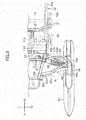
- FIG. 3 is a plan view showing the vehicle frame 30, the left ski 41 L, and the suspension 45.
- FIG. 4 is a front view showing the vehicle frame 30, the right and left skis 41R and 41 L, and the suspensions 45.
- FIG. 5 is a perspective view showing the vehicle frame 30, the left ski 41 L, and the suspension 45.
- Y1 and Y2 illustrated in the above described in drawings indicate forward and rearward directions, respectively. Further, Z1 and Z2 indicate upward and downward directions, respectively. X1 and X2 indicate rightward and leftward directions, respectively.
- the snowmobile 1 includes a drive system for driving the track belt 16.
- the drive system includes an engine 11, a transmission 12, a secondary shaft 13 and a track belt drive shaft 14.
- the engine 11 includes a crank case 11 d (see FIG. 3 ) accommodating the crank shaft 11 a.
- the engine 11 includes a cylinder block 11 b attached to the crank case 11d and a cylinder head 11c attached to the cylinder block 11b.
- the cylinder block 11 b has a cylinder formed therein.
- the cylinder head 11c has an intake passage and an exhaust passage formed therein that are connected to the combustion chamber inside the cylinder.
- the crank case 11d is located further rearward than a ski support frame 31 (see FIG. 1 ) constituting the front portion of the vehicle frame 30 (the ski support frame 31 will be described later).
- the cylinder block 11b and the cylinder head 11c are attached to the upper side of the crank case 11d and arranged such that the axis line of the cylinder is inclined backward. Accordingly, the engine 11 does not overlap with the later-described arms 42 and 43 supporting the skis 41 R and 41 L in side view of the vehicle body.
- the posture of engine 11 is not limited to the example of snowmobile 1. For example, a part of the engine 11 may be overlapped with the arms 42 and 43 in side view of the vehicle body.
- the transmission 12 is, for example, a continuously variable transmission, and includes a driving pulley 12a receiving a torque from a crank shaft 11 a and a driven pulley 12b receiving a torque from the driving pulley 12a, as shown in FIG. 2A .
- a belt 12c (see FIG. 1 ) is wound around the pulleys 12a and 12b for transmitting the torque of the driving pulley 12a to the driven pulley 12b.
- the driving pulley 12a is mounted on the crank shaft 11 a.
- the driven pulley 12b is mounted on the secondary shaft 13.
- the secondary shaft 13 is located further rearward than the crank shaft 11 a and located higher than the crank shaft 11a.
- the driving pulley 12a and the driven pulley 12b are mounted, for example, at the end of the crank shaft 11a and the end of the secondary shaft 13, respectively. As shown in FIG. 3 , the driving pulley 12a and the driven pulley 12b are located, for example, outwardly in the vehicle width direction from a later-described engine support frame 32 (pulleys 12a and 12b are located leftward in the vehicle width direction from the engine support frame 32, in the example of snowmobile 1). Unlike the example of snowmobile 1, the driving pulley 12a and the driven pulley 12b may be located inside the engine support frame 32 in the vehicle width direction.
- the arrangement of the transmission 12 is not limited to the example of snowmobile 1.
- the driving pulley 12a may be mounted on a primary shaft different from the crank shaft 11 a.
- the transmission 12 is not a continuously variable transmission.
- "secondary shaft" means a shaft on which the driven member of the transmission 12 is mounted. That is, for the snowmobile including the continuously variable transmission as the transmission 12, the secondary shaft means the shaft on which the driven pulley 12b is mounted.
- the secondary shaft means a shaft on which the driven gear of the transmission 12 is mounted (the driven gear means a gear that engages with a driving gear mounted on the primary shaft).
- the track belt drive shaft 14 is connected to the secondary shaft 13 through a belt, a chain, and the like, and receives a torque from the secondary shaft 13 to rotate.
- the track belt drive shaft 14 has a sprocket 14b mounted thereon that is located inside the track belt 16 and is engaged with the track belt 16.
- Guide wheels 15a, 15b and 15c for guiding the track belt 16 and a slide rail 17 for guiding the track belt 16 are further arranged inside the track belt 16.
- the slide rail 17 presses the track belt 16 toward the snow surface.
- the snowmobile 1 includes, in front of the seat 8, a steering handle 21 for the driver to steer the skis 41R and 41L.
- the snowmobile 1 includes a steering column 22 extending diagonally downward and forward from the center portion of the steering handle 21.
- the steering handle 21 is connected to the skis 41 R and 41 L through the steering column 22, a tie rod 24 (see FIG. 4 ) and a knuckle 44 which will be described later.
- the snowmobile 1 includes a fuel tank 9 for storing the fuel for the engine 11. As shown in FIG. 1 , the fuel tank 9 is disposed, for example, between the steering column 22 and the seat 8. In the example of snowmobile 1, the engine 11 is located below the steering column 22 and the fuel tank 9.
- the snowmobile 1 includes the right ski 41 R and the left ski 41 L (see FIG. 4 ).
- the vehicle frame 30 of the snowmobile 1 includes a ski support frame 31.
- the skis 41 R and 41 L are disposed outwardly in the vehicle width direction from the ski support frame 31. That is, the right ski 41 R is disposed in the right direction of the ski support frame 31, and the left ski 41 L is disposed in the left direction of the ski support frame 31.
- the snowmobile 1 includes an upper arm 42 and a lower arm 43 located below the upper arm 42.
- the upper arm 42 includes proximal portions 42a and 42b connected to the ski support frame 31 and extends outwardly from the proximal portions 42a and 42b in the vehicle width direction.
- the lower arm 43 includes proximal portions 43a and 43b connected to the ski support frame 31 and extends outwardly from the proximal portions 43a and 43b in the vehicle width direction. That is, the snowmobile 1 includes an upper arm 42 and a lower arm 43 that are located to the right of the ski support frame 31 and that connect the ski support frame 31 and the right ski 41R. In addition, the snowmobile 1 includes a left arm 42 and a lower arm 43 that are located to the left of the ski support frame 31 and that connect the ski support frame 31 and the left ski 41 L. The distal end 42p of the upper arm 42 and the distal end 43p of the lower arm 43 are connected to the knuckle 44.
- ski support frame means a portion of the vehicle frame 30 to which the proximal portions 43a and 43b of the lower arm 43 and the proximal portions 42a and 42b of the upper arm 42 are connected.
- the ski support frame 31 may be integrally formed with another part of the vehicle frame 30 (for example, an engine support frame 32 to be described later).
- the ski support frame 31 may be formed separately from other portions of the vehicle frame 30 and may be fixed to the other portion by a fixing means such as bolts or welding.
- the proximal portions 43a and 43b of the lower arm 43 are located closer to the center in the vehicle width direction than the proximal portions 42a and 42b of the upper arm 42.
- the position of the distal end of the upper arm 42 is substantially equal to the position of the distal end of the lower arm 43. Therefore, the lower arm 43 is longer than the upper arm 42.
- the proximal portions 42a, 42b, 43a and 43b of the arms 42 and 43 are connected to the ski support frame 31 so as to be rotatable. That is, the proximal portions 42a, 42b, 43a and 43b of the arms 42 and 43 are connected to the ski support frame 31 so that the arms 42 and 43 are allowed to move up and down about the proximal portions 42a, 42b, 43a and 43b.
- This connections of the arms 42 and 43 allow the knuckle 44 and the skis 41 R and 41L to move up and down relative to the vehicle frame 30.
- the upper arm 42 includes a front rod 42m and a rear rod 42n located behind the front rod 42m.
- the lower arm 43 includes a front rod 43m and a rear rod 43n located behind the front rod 43m.
- the proximal portion 42a of the front rod 42m, the proximal portion 42b of the rear rod 42n, the proximal portion 43a of the front rod 43m, and the proximal portion 43b of the rear rod 43n are connected to the ski support frame 31.
- the proximal portions 42a, 42b, 43a and 43b are provided with shafts.
- the shafts of the proximal portions 42a, 42b, 43a, and 43b are supported by the arm connecting portions 31 a, 31 b, 31 c, and 31 d (see FIGS. 2A and 5 ) formed on the lateral side of the ski support frame 31, respectively.
- the ski support frame 31 is formed of a plurality of panels.
- the ski support frame 31 includes left and right side panels 31g located away from each other in the vehicle width direction (left-right direction), and a front panel 31f fixed to the front edges of the left and right side panels 31g.
- the arm connecting portions 31a, 31b, 31c, and 31d supporting the arms 42 and 43 may be fixed to the panels 31f and 31g by welding, or integrally formed with the panels 31f and 31g.
- the side panel 31g is obliquely arranged toward the center of the vehicle width direction.
- the side panel 31g extends from the portion having the proximal portions 42a and 42b of the upper arm 42 connected thereto (that is, the portion having the arm connecting portions 31a and 31b formed thereon) to the portion having the proximal portions 43a and 43b of the lower arm 43 connected thereto (that is, the portion having the arm connecting portions 31c and 31 d formed thereon).
- the width of the front panel 31f in the left-right direction gradually decreases downward in conformity with the inclination of the left and right side panels 31g.
- the structure of the ski support frame 31 is not limited to the example described here.
- the ski support frame 31 may be composed of a plurality of pipes.
- the arm connecting portions 31a, 31b, 31c, and 31d may be fixed to the pipes.
- the upper arm 42 is substantially triangular in plan view thereof, and the two rods 42m and 42n of the upper arm 42 are connected to a common end (that is, the distal end 42p of the upper arm 42).
- the lower arm 43 is also substantially triangular in plan view thereof, and the two rods 43m and 43n of the lower arm 43 are connected to a common end (that is, the distal end 43p of the lower arm 43).
- the distal end 42p of the upper arm 42 is connected to the knuckle 44 with a ball joint, for example, so that the angle between the knuckle 44 and the upper arm 42 is allowed to change.
- the distal end 43p of the lower arm 43 is connected to the knuckle 44 with a ball joint, for example, so that the angle between the knuckle 44 and the lower arm 43 is allowed to change.
- the vehicle frame 30 includes an engine support frame 32 supporting the engine 11.
- the engine support frame 32 includes side frames 32 a (see FIGS. 3 and 5 ) located along left and right side faces of the engine 11.
- the engine support frame 32 includes a lower frame 32c covering the lower side and the front side of the engine 11 and fixed to the lower portion of the side frame 32a.
- the ski support frame 31 is fixed to the front side of the engine support frame 32.
- the structure of the engine support frame 32 and the structure of the ski support frame 31 are not limited to the example of snowmobile 1 and may be changed.
- the lower arm 43 of the snowmobile 1 is supported at a higher position than that of the conventional snowmobiles.
- the proximal portions 43a and 43b of the lower arm 43 are connected to the ski support frame 31 at a position higher than the lower end 11 g of the engine 11.
- the proximal portions 43a and 43b of the lower arm 43 are positioned higher than the rotational center C1 of the crank shaft 11 a.
- the proximal portions 43a and 43b of the lower arm 43 are located above the horizontal plane H1 passing through the rotational center C1 in side view of the vehicle body.
- the horizontal plane H1 is defined as a plane parallel to skis 41R and 41L in a state in which no load is applied to the vehicle body. "A state in which no load is applied to the vehicle body” means a state in which the driver does not ride on the vehicle and only the vehicle's own weight is applied to the vehicle body.
- the two proximal portions 43a and 43b of the lower arm 43 may be located at the same height as the rotational center C1 of the crank shaft 11a. That is, the horizontal plane H1 may cross the proximal portions 43a and 43b of the lower arm 43 in side view of the vehicle body.
- the above described layout can raise the position of the lower arm 43, while keeping the center position of gravity of the driving system low.
- the center position of gravity of the vehicle body is prevented from becoming high, and running resistance can be reduced when the vehicle travels in deep snow.
- the height of the center position of gravity of the drive system including the engine is located in a range from the vicinity of the crank shaft of the engine to the vicinity of the height of the secondary shaft.
- the center position of gravity of the driving system and the position of the lower arm are greatly apart in the vertical direction.
- the proximal portions 43a and 43b of the lower arm 43 in the snowmobile 1 are located higher than the rotational center C1 of the crank shaft 11a, the height of the lower arm 43 is closer to the height of the center of gravity of the drive system than that in the conventional snowmobiles. As a result, running resistance in traveling in deep snow can be reduced without raising the center position of gravity of the vehicle body in the vertical direction.
- the height h1 from the lower ends of the skis41R and 41 L to the proximal portions 43a and 43b of the lower arm 43 is 320 mm or more in a state where no load is applied to the vehicle body.
- the height h1 may be 330 mm or more.
- the height h1 is preferably 550 mm or less.
- the position of the proximal portion of one of the two proximal portions 43a and 43b of the lower arm 43 may be higher than the rotational center C1 of the crank shaft 11a, whereas the position of the other proximal portion may be lower than the rotational center C1 of the crank shaft 11a.
- the lower arm 43 may be inclined such that the proximal portion 43a of the front rod 43m is higher than the proximal portion 43b of the rear rod 43n.
- the proximal portion 43a of the front rod 43m may be located higher than the horizontal plane H1 and the proximal portion 43b of the rear rod 43n may be located lower than the horizontal plane H1.
- a different portion from the proximal portions 43a and 43b of the lower arm 43 may be located higher than the horizontal plane H1 in a state in which no load is applied to the vehicle body.
- the lower arm 43 may be curved such that the middle portion in the left-right direction of the lower arm 43 bulges upward.
- the highest portion of the lower arm 43 may be located higher than the horizontal plane H1.
- the proximal portions 43a and 43b of the lower arm 43 rotate about the axis Ax1 shown in FIG. 2B .
- the axis Ax1 passes through a position above the rotational center C1 of the crank shaft 11 a. That is, the intersection point Q4 at which the axis Ax1 crosses the vertical line V2 passing through the rotational center C1 is positioned higher than the rotational center C1.
- the axis Ax1 may pass through the position of the rotational center C1 of the crank shaft 11a. That is, the intersection point Q4 is positioned at the same height as the rotational center C1.
- the lower arm 43 may be inclined such that its front portion is higher than its rear portion, and thus the axis Ax1 may be inclined relative to the horizontal plane H1. In this case, unlike the example of snowmobile 1, the axis Ax1 may go through the position below the rotational center C1 of the crank shaft 11 a.
- the plane P1 shown in FIG. 2B is an imaginary plane passing through the distal end 43p of the lower arm 43 and the distal end 42p of the upper arm 42 and parallel to the vehicle width direction.
- the intersection point Q1 at which the plane P1 and the axis Ax1 cross to each other may be located higher than the rotational center C1 of the crank shaft 11 a. That is, the intersection point Q1 may be located above the horizontal plane H1.
- the vehicle frame 30 includes a belt housing 33 covering the upper side of the track belt 16.
- the seat 8 is located above the belt housing 33.
- the belt housing 33 includes, on the lateral sides thereof, foot rests 33a for the driver to rest the feet on.
- the foot rest 33a extends rearward from the foremost portion of the belt housing 33.
- the proximal portions 43a and 43b of the lower arm 43 are located higher than the foot rest 33a. This positional relationship can effectively prevent a lot of snow from hitting the lower arm 43, if the foot rest 33a is located at a low position.
- the lower arm 43 is located higher than the foremost portion of the foot rest 33a.
- the snowmobile 1 includes a track belt drive shaft 14. As shown in FIG. 2B , the proximal portions 43a and 43b of the lower arm 43 may be positioned higher than the rotational center of the track belt drive shaft 14. Further, the proximal portions 43a and 43b of the lower arm 43 may be located higher than the lower end of the driving pulley 12a of the transmission 12.
- the distal end 43p of the lower arm 43 is connected to the knuckle 44. As shown in FIG. 2B , the distal end 43p of the lower arm 43 is located higher than the lower end 11g of the engine 11 in a state where no load is applied to the vehicle body.
- a state where no load is applied to the vehicle body means, as described above, a state in which the driver does not ride on the vehicle and only the vehicle's own weight is applied to the vehicle body.
- the lower arm 43 is arranged substantially in parallel with the horizontal plane in a state where no load is applied to the vehicle body.
- the distal end 43p of the lower arm 43 is positioned higher than the rotational center C1 of the crank shaft 11a, similarly to the proximal portions 43a and 43b.
- the distal end 43p of the lower arm 43 is located above the horizontal plane H1 passing through the rotational center C1 of the crank shaft 11a.
- the lower arm 43 may extend obliquely downward and outwardly in the vehicle width direction from the proximal portions 43a and 43b in a state where no load is applied to the vehicle body. In that case, the distal end 43p of the lower arm 43 may be positioned below the horizontal plane H1.
- the height h1 from the lower ends of the skis 41 R and 41L to the proximal portions 43a and 43b of the lower arm 43 is greater than half of the height h2 from the lower ends of the skis 41 R and 41L to the proximal portions 42a and 42b of the upper arm 42. Also, the height from the lower ends of the skis 41 R and 41 L to the distal end 43p of the lower arm 43 is larger than half of the height from the lower ends of the skis 41 R and 41L to the distal end 42p of the upper arm 42.
- the upper arm 42 is connected to the ski support frame 31 at a high position. More specifically, as shown in FIG. 2B , the proximal portions 42a and 42b of the upper arm 42 are connected to the ski support frame 31 at a position higher than the rotational center C2 of the secondary shaft 13. That is, the proximal portions 42a and 42b of the upper arm 42 are positioned above the horizontal plane H2 passing through the rotational center C2 of the secondary shaft 13. The proximal portions 42a and 42b of the upper arm 42 are rotatable about the axis Ax2 (see FIG. 2B ) so that the upper arm 42 is allowed to move up and down about the proximal portions 42a and 42b.
- the axis Ax 2 of the proximal portions 42a and 42b passes through a position above the rotational center C2 of the secondary shaft 13. That is, the intersection point Q3 at which the axis Ax 2 crosses the vertical line V1 passing through the rotational center C2 is located above the rotational center C2.
- the above described location of the upper arm 42 can reduce the force acting on the vehicle frame 30 from the knuckle 44 via the upper arm 42 or prevent increase of the force. More specifically, when the skis 41R and 41L moves up and down, the force acting on the skis 41R and 41 L from the snow surface is transmitted to the vehicle frame 30 via the upper arm 42 and the knuckle 44. At this time, the knuckle 44 works like a lever, and the connecting portion between the knuckle 44 and the lower arm 43 words as the fulcrum of the lever. For example, when skis 41R and 41 L move upward, the left and right knuckles 44 tilt such that the lower ends thereof widen outwardly in the vehicle width direction because the upper arms 42 are shorter than the lower arms 43.
- the knuckle 44 and the vehicle frame 30 pull each other through the upper arm 42. That is, a pulling force acts between the knuckle 44 and the vehicle frame 30 via the upper arm 42.
- the upper arms 42 are supported at a position higher than the convention snowmobiles. Therefore, a sufficient distance can be ensured between the distal end 43p of the lower arm 43 and the distal end 42p of the upper arm 42 in the vertical direction (as described above, the distal end 43p is the connection portion between the lower arm 43 and the knuckle 44, and the distal end 42p is the connection portion between the upper arm 42 and the knuckle 44).
- the lever ratio of the knuckle 44 reduces, and thus the force acting on the vehicle frame 30 from the knuckle 44 via the upper arm 42 can be reduced.
- it can be prevented that the force acting on the vehicle frame 30 from the knuckle 44 via the upper arm 42 is increased due to raising the position of the lower arm 43.
- the height of the center position of gravity of the drive system including the engine is located in the range from the vicinity of the crank shaft of the engine to the vicinity of the secondary shaft.
- the rotational center C2 of the secondary shaft 13 is located lower than the axis Ax2 of the proximal portions 42a and 42b. Therefore, it is possible to keep the center of gravity of the driving system at a low position. In other words, it is possible to prevent the center position of gravity of the vehicle body from becoming high.
- the proximal portions 42a and 42b of the upper arm 42 may be arranged such that the axis Ax2 passes through the rotational center C2 of the secondary shaft 13.
- the two proximal portions 42a and 42b of the upper arm 42 may be located at the same height and the axis Ax2 may be arranged horizontally.
- the lower arm 43 may be inclined such that the proximal portion 43a of the front rod 43m is higher than the proximal portion 43b of the rear rod 43n.
- the axis Ax2 may be inclined relative to the horizontal plane H2.
- the height h2 (see FIG. 2B ) from the lower end of the skis 41 R and 41 L to the proximal portions 42a and 42b of the upper arm 42 is 550 mm or more.
- the height h2 is preferably 560 mm or more.
- the height h3 (see FIG. 2B ) from the lower end 11g of the engine 11 to the proximal portions 42a and 42b of the upper arm 42 is 300 mm or more.
- the height h3 may be 350 mm or more.
- the height h3 may be 380 mm or more.
- the proximal portions 42a and 42b of the upper arm 42 are positioned higher than the upper end of the driven pulley 12b. That is, the intersection point Q3 at which the axis Ax 2 crosses the vertical line V1 passing through the rotational center C2 of the secondary shaft 13 is located above the upper end of the driven pulley 12b.
- the proximal portions 42a and 42b of the upper arm 42 may be located at the same height as the upper end of the driven pulley 12b.
- the distal end 42p of the upper arm 42 is connected to the knuckle 44.
- the position of the distal end 42p of the upper arm 42 is higher than the position of the rotational center C2 of the secondary shaft 13. That is, in a state where no load is applied to the vehicle body, the height from the lower ends of the skis 41 R and 41 L to the distal end 42p of the upper arm 42 is greater than the height from the lower ends of the skis 41R and 41 L to the rotational center C2 of the secondary shaft 13.
- FIG. 2B shows an imaginary plane P1 passing through the distal end 43p of the lower arm 43 and the distal end 42p of the upper arm 42 and parallel to the vehicle width direction.
- the intersection point Q2 at which the axis Ax 2 passing through the rotational center of the proximal portions 42a and 42b of the upper arm 42 crosses the imaginary plane P1 is located higher than the rotational center C2 of the secondary shaft 13. That is, the intersection point Q2 is located above the horizontal plane H2.
- the skis 41 R and 41 L are connected to the lower ends 44 f of the knuckles 44.
- the upper arm 42 is connected to the upper end 44e (the first connecting portion) of the knuckle 44.
- the distance D1 (see FIG. 2B ) from the lower end 44f of the knuckle 44 to the upper end 44e is, for example, 430 mm or more.
- the distance D1 may be 470 mm or more.
- the distance D1 may be 500 mm or more.
- the knuckle 44 includes a cross bar 44d (second connecting portion) in a midway portion thereof in the vertical direction.
- the lower arm 43 is connected to the cross bar 44d.
- the cross bar 44d is positioned lower than the middle position (center position) between the lower end 44f and the upper end 44e of the knuckle 44.
- the cross bar 44d may be located at the same height as the middle position between the lower end 44f and the upper end 44e of the knuckle 44.
- the cross bar 44d may be located higher than the middle position between the lower end 44f and the upper end 44e of the knuckle 44.
- the vehicle frame 30 includes an engine support frame 32 and a ski support frame 31.
- the ski support frame 31 is located foreword of and connected to the engine support frame 32.
- the ski support frame 31 is shifted upward relative to the engine support frame 32. That is, as shown in FIG. 5 , the lower end 31 e at the rearmost portion of the ski support frame 31 is connected to the engine support frame 32 and is located upward from the lower end 32f of the engine support frame 32. This allows the lower arm 43 and the upper arm 42 to be supported at high positions.
- the ski support frame 31 includes, at the lowermost position thereof, arm connecting portions 31 c and 31 d for supporting the proximal portions 43a and 43b of the lower arm 43.
- the ski support frame 31 includes a portion located upward from the lower end 32f of the foremost of the engine support frame 32.
- the portion has the arm connecting portions 31c and 31d formed thereon.
- the ski support frame 31 is composed of a plurality of panels 31f and 31g.
- the arm connecting portions 31a and 31b are fixed to the lowermost portion of the side panel 31g.
- the lower end 31e of the rearmost portion of the side panel 31g is connected to the engine support frame 32.
- the ski support frame 31 may be composed of a plurality of pipes.
- a pipe having the arm connecting portions 31c and 31d formed thereon may be located upward from the lower end 32f of the engine support frame 32 and connected to the engine support frame 32.
- the ski support frame 31 and the engine support frame 32 are formed separately and are fixed to each other by a fixing means such as welding or bolts, for example.
- the ski support frame 31 and the engine support frame 32 may be integrally formed.
- FIG. 2A shows a straight line L1 that is an imaginary straight line connecting the foremost of the proximal portion 43a of the front rod 43m of the lower arm 43 and the lower end 11g of the engine 11.
- the proximal portion 43a of the lower arm 43 is connected to the ski support frame 31 at a position higher than the lower end 11g of the engine 11. Therefore, the straight line L1 is inclined relative to the horizontal plane passing through the lower end 11g of the engine 11.
- the angle ⁇ 1 between the imaginary straight line L1 and the horizontal plane is 15 degrees or more and 45 degrees or less in side view of the vehicle body.
- a cover member 51 is disposed under the ski support frame 31.
- the cover member 51 includes a lower surface portion 51 a covering the lower side of the ski support frame 31 and extending obliquely forward and upward.
- the cover member 51 prevents a lot of snow from hitting the lower portion of the engine support frame 32 and prevents a lot of snow from hitting the lower portion of the engine 11.
- the lower surface portion 51a of the cover member 51 extends obliquely forward and upward from the lower end 32f of the foremost of the engine support frame 32.
- the lower surface portion 51 a is curved so as to bulge downward.
- the distance between the lower surface portion 51 a and the imaginary straight line L1 is the maximum D1 at the midway position between the front end of the lower surface portion 51 a and the rear end of the lower surface portion 51 a.
- the cover member 51 includes lateral surface portions 51 b.
- the lateral surface portion 51 b extends upward in side view of the vehicle body from the lower surface portion 51 a and is connected to the lower portion of the ski support frame 31.
- the lateral surface portion 51b extends diagonally upward from the lower surface portion 51 a toward the center of the vehicle width direction. More specifically, the lateral surface portions 51 b obliquely extend from the left and right edges of the lower surface portion 51 a toward the lower edges of the ski support frame 31.
- the lateral surface portion 51 b may not be inclined. That is, the lateral surface portion 51 b may be arranged vertically.
- the cover member 51 does not include the lateral surface portion.
- the cover member 51 is formed separately from the ski support frame 31 and is fixed to the ski support frame 31 by a fixing means such as welding or bolts. As shown in FIG. 5 , the rear edge 51c of the lateral surface portion 51b is connected to the engine support frame 32. In the example of snowmobile 1, the cover member 51 is formed separately from the engine support frame 32 and is fixed to the engine support frame 32 by a fixing means such as welding or bolts. More specifically, the rear edge 51c of the lateral surface portion 51b is fixed to the front surface of the lower frame 32c of the engine support frame 32.
- the connecting structure of the cover member 51 is not limited to the example of snowmobile 1.
- the cover member 51 may be integrally formed with a member of the the ski support frame 31.
- the cover member 51 may be integrally formed with a member of the engine support frame 32.
- the snowmobile 1 includes suspensions 45.
- the upper ends 45b of the suspensions 45 are connected to the ski support frame 31.
- the suspension 45 is located between the front rod 42m and the rear rod 42n of the upper arm 42.
- the upper end 45 b of the suspension 45 is located higher than the proximal portions 42a and 42b of the upper arm 42.
- the lower end 45a of the suspension 45 is connected to the lower arm 43.
- the upper end 45b of the suspension 45 is positioned higher than the rotational center C2 of the secondary shaft 13. That is, the upper end 45b of the suspension 45 is located above the horizontal plane H2 passing through the rotational center C2.
- This arrangement of the suspension 45 prevents the angle between the suspension 45 and the lower arm 43 from decreasing due to raising the position of the lower arm 43.
- the suspension 45 can effectively receive the force acting on the lower arm 43 when the skis 41 R and 41 L moves up and down, and provide a suitable damping function.
- the ski support frame 31 includes a suspension connecting portion 31f to which the upper end 45b of the suspension 45 is connected.
- the ski support frame 31 includes a portion protruding upward from a portion on which the arm connecting portions 31a, 31b, 31c, and 31d are formed.
- the protruding portion has the suspension connecting portion 31f formed thereon.
- the ski support frame 31 includes the side panel 31 g to which the arm connecting portions 31 a, 31b, 31c, and 31d are fixed.
- the upper portion 31h of the ski support frame 31 further protrudes upward from the upper edge of the side panel 31g.
- the upper portion 31h is, for example, a plate-like portion extending further upward from the side panel 31g, and is formed integrally with the side panel 31g.
- the suspension connecting portion 31f is fixed to the upper portion 31 h.
- the structure of the ski support frame 31 is not limited to the example of snowmobile 1.
- the upper portion 31 h may not be formed integrally with the side panel 31g. In this case, the upper portion 31h may be welded or bolted to the side panel 31g.
- the ski support frame 31 includes two upper portions 31h that are located away from each other in the vehicle width direction (lateral direction).
- the left and right suspensions 45 are respectively connected to the upper portions 31 h.
- a rod 31 i extends in the vehicle width direction and is fixed to the upper portions 31 h. This rod 31 i improves the rigidity of the ski support frame 31 against the force acting on the ski support frame 31 from the suspensions 45.
- the upper end 45b of the suspension 45 is positioned higher than the rotational center C2 of the secondary shaft 13.
- the upper end 45b of the suspension 45 is located higher than the upper end of the driven pulley 12b mounted on the secondary shaft 13.
- the upper end 45b of the suspension 45 is located higher than the lower end 9a (see FIG. 1 ) of the fuel tank 9. Further, the upper end 45b of the suspension 45 is positioned higher than the lower end 8a (see FIG. 1 ) of the seat 8.
- the snowmobile 1 includes a tie rod 24 for steering the skis 41 R and 41 L.
- the tie rod 24 is indirectly or directly connected to the lower end of the steering column 22.
- the tie rod 24 extends in the vehicle width direction and includes tip ends 24a (see FIG. 2A ) connected to the knuckles 44.
- the rotation of the steering handle 21 and the steering column 22 is transmitted to the knuckle 44 through the tie rod 24.
- the tie rod 24 is located higher than the lower arm 43, and the tip end 24a of the tie rod 24 is located higher than the rotational center C1 of the crank shaft 11 a (see FIG. 2B ).
- the knuckle 44 includes a front post portion 44a and a rear post portion 44b.
- the upper end of the front post portion 44a and the upper end of the rear post portion 44b are connected to each other.
- the lower end of the front post portion 44a and the lower end of the rear post portion 44b are also connected to each other.
- a cross bar 44d extends between and is fixed to a midway portion of the front post portion 44a and a midway portion of the rear post portion 44b.
- the distal end 43p of the lower arm 43 is located above and connected to the cross bar 44d.
- the structure of the knuckle 44 is not limited to the example shown in FIG. 2A .
- the knuckle 44 may further include another cross bar located below the cross bar 44d and fixed to the front post portion 44a and the rear post portion 44b.
- the tip end of the tie rod 24 is connected to the rear post portion 44b.
- the present invention is not limited to the snowmobile 1 explained above, and various modifications may be made.
- the proximal portions 42a and 42b of the upper arm 42 are connected to the ski support frame 31 at the positions higher than the rotational center C2 of the secondary shaft 13. Further, the axis Ax2 of the proximal portions 42a and 42b of the upper arm 42 passes through the position above the rotational center C2 of the secondary shaft 13. Unlike the example of snowmobile 1, the proximal portions 42a and 42b of the upper arm 42 may be positioned lower than the rotational center C2 of the secondary shaft 13. Further, the axis Ax 2 of the proximal portions 42a and 42b of the upper arm 42 may pass through a position below the rotational center C2 of the secondary shaft 13.
Landscapes
- Engineering & Computer Science (AREA)
- Chemical & Material Sciences (AREA)
- Combustion & Propulsion (AREA)
- Transportation (AREA)
- Mechanical Engineering (AREA)
- Vehicle Body Suspensions (AREA)
Abstract
Description
- The present specification relates to a support structure of skis in snowmobiles.
- As disclosed in
US Patent Application Publication No. 2013/0032417 , snowmobiles have upper arms and lower arms for supporting the left and right skis. The proximal portion of the upper arm and the proximal portion of the lower arm are connected to the front portion of the vehicle frame. The upper arm and the lower arm include distal ends connected to a knuckle. The ski is connected to the lower end of the knuckle. The proximal portion of the upper arm and the proximal portion of the lower arm are rotatably connected to the vehicle frame so that the ski and the knuckle are allowed to move up and down relative to the vehicle frame. In conventional snowmobiles, as disclosed in the above patent document, the proximal portion of the lower arm is connected to a portion of the vehicle frame that is continuously arranged to the lower surface of the engine, and is located at approximately the same height as the lower end of the engine. - In the conventional snowmobiles, the lower arm is located at a low position and is connected to the vehicle frame. For example, in the snowmobile of
US Patent Application Publication No. 2013/0032417 , the proximal portion of the lower arm is located at approximately the same height as the lower end of the engine, as described above. Since such a structure places the overall lower arm at the lower position, a lot of snow may hit the lower arm to cause running resistance against the vehicle when the vehicle runs on deep snow. If the positional relationship between the engine and the lower arm in the conventional snowmobiles is maintained and the position of the lower arm is raised in order to reduce the running resistance due to snow, the center position of gravity of the vehicle body becomes high because the position of the engine also becomes higher. - One of the objects of the present specification is to propose a snowmobile that can reduce the running resistance due to snow and can prevent the center position of gravity of the vehicle body from being higher.
- (1-1) A snowmobile according to an embodiment described in the present specification includes: a vehicle frame including a ski support frame in a front portion of the vehicle frame; a ski disposed outwardly in a vehicle width direction from the ski support frame; an upper arm including a proximal portion connected to the ski support frame, extending outwardly in the vehicle width direction from the proximal portion, and connecting the ski support frame and the ski; a lower arm disposed below the upper arm, including a proximal portion connected to the ski support frame, extending outwardly in the vehicle width direction from the proximal portion, and connecting the ski support frame and the ski; and an engine including a crank shaft and located further rearward than the ski support frame. The proximal portion of the lower arm is located higher than a lower end of the engine, and at least a portion of the lower arm is located at the same height as a rotational center of the crank shaft, or located higher than the rotational center of the crank shaft. This snowmobile can prevent the center position of gravity of the vehicle body from being high and reduce the running resistance when traveling in deep snow.
- (1-2) A snowmobile according to an embodiment described in the present specification includes: a vehicle frame including a ski support frame in a front portion of the vehicle frame; a ski disposed outwardly in a vehicle width direction from the ski support frame; an upper arm including a proximal portion connected to the ski support frame, extending outwardly in the vehicle width direction from the proximal portion, and connecting the ski support frame and the ski; a lower arm disposed below the upper arm, including a proximal portion connected to the ski support frame, extending outwardly in the vehicle width direction from the proximal portion, and connecting the ski support frame and the ski; and an engine including a crank shaft and located further rearward than the ski support frame. The proximal portion of the lower arm is located higher than a lower end of the engine. In addition, an angle between an imaginary straight line and a horizontal plane is 15 degrees or more and 45 degrees or less in side view of the vehicle body, where the imaginary straight line is defined as a straight line that connects a foremost of the proximal portion of the lower arm and the lower end of the engine in side view of the vehicle body. This snowmobile can prevent the center position of gravity of the vehicle body from being high and reduce the running resistance when traveling in deep snow.
- (1-3) A snowmobile according to an embodiment described in the present specification includes: a vehicle frame including a ski support frame in a front portion of the vehicle frame; a ski disposed outwardly in a vehicle width direction from the ski support frame; an upper arm including a proximal portion connected to the ski support frame, extending outwardly in the vehicle width direction from the proximal portion, and connecting the ski support frame and the ski; a lower arm disposed below the upper arm, including a proximal portion connected to the ski support frame, extending outwardly in the vehicle width direction from the proximal portion, and connecting the ski support frame and the ski; and an engine including a crank shaft and located further rearward than the ski support frame. In side view of the vehicle body, a foremost of the proximal portion of the lower arm is located at a height of 320 mm or more from the lower end of the ski. This snowmobile can prevent the center position of gravity of the vehicle body from being high and reduce the running resistance when traveling in deep snow.
- (2) In the snowmobile described in any one of (1-1), (1-2) and (1-3), the lower arm may include a front rod extending outwardly in the vehicle width direction from the ski support frame and including the proximal portion, and a rear rod located rearward of the front rod, extending outwardly in the vehicle width direction from the ski support frame and including the proximal portion. In addition, at least one of the proximal portion of the front rod and the proximal portion of the rear rod may be located at the same height as the rotational center of the crank shaft, or located higher than the rotational center of the crank shaft.
- (3) In the snowmobile described in any one of (1-1), (1-2) and (1-3), the vehicle frame may include an engine support frame supporting the engine, and the ski support frame may be shifted upwardly from the engine support frame.
- (4) In the snowmobile described in (3), a cover member may be disposed under the ski support frame and may include a lower surface portion covering a lower side of the ski support frame. This snowmobile can prevent a lot of snow from hitting the engine and the frame supporting the engine and the like.
- (5) In the snowmobile described in (4), the cover member may include a lateral surface portion extending upwardly in side view of the vehicle body from the lower surface portion and connected to the ski support frame.
- (6) In the snowmobile described in any one of (1-1), (1-2) and (1-3), the proximal portion of the lower arm and the proximal portion of the upper arm may be rotatably connected to the ski support frame so that the ski is allowed to move up and down, the proximal portion of the lower arm may have a rotational center thereof and an axis that passes through the rotational center, and the axis may go through the rotational center of the crank shaft in side view of the vehicle body, or through a position above the rotational center of the crank shaft in side view of the vehicle body.
- (7) In the snowmobile described in any one of (1-1), (1-2) and (1-3), the ski may be connected to a lower end of a knuckle, each of the lower arm and the upper arm may include a distal end connected with the knuckle, the proximal portion of the lower arm and the proximal portion of the upper arm may be rotatably connected to the ski support frame so that the ski and the knuckle are allowed to move up and down. In addition, an intersection point at which an imaginary plane and an axis crosses each other may be located higher than the rotational center of the crank shaft, where the imaginary plane is defined as a plane that passes through the distal ends of the the lower arm and the upper arm and is parallel to the vehicle width direction, and where the axis is defined as a straight line that passes through a rotational center of the proximal portion of the lower arm.
- (8) In the snowmobile described in any one of (1-1), (1-2) and (1-3), the ski may be connected to a lower end of a knuckle, each of the lower arm and the upper arm may include a distal end connected with the knuckle, and the distal end of the lower arm may be located higher than the lower end of the engine.
- (9) In the snowmobile described in (8), the distal end of the lower arm may be located higher than the rotational center of the crank shaft.
- (10) In the snowmobile described in any one of (1-1), (1-2) and (1-3), the ski may be connected to a lower end of a knuckle, a tie rod that turns the knuckle in accordance with steering of a driver may have a distal end connected with the knuckle, and the distal end of the tie rod may be located higher than the rotational center of the crank shaft.
- (11) The snowmobiles described in (1-1), (1-2) or (1-3) may further include a foot rest for a driver to rest the foot thereon. The proximal portion of the lower arm may be located higher than the lowest portion of the foot rest. This snowmobile can prevent a lot of snow from hitting the lower arm even if the position of foot rest is lowered.
- (12) In the snowmobile described in any one of (1-1), (1-2) and (1-3), the proximal portion of the lower arm and the proximal portion of the upper arm may be rotatably connected to the ski support frame so that the ski is allowed to move up and down, and the proximal portion of the upper arm may be located higher than a rotational center of a secondary shaft that receives drive force from the crank shaft.
- (14) In the snowmobile described in any one of (1-1), (1-2) and (1-3), a cover member may be disposed under the ski support frame and may include a lower surface portion covering the lower side of the ski support frame and extending forwardly and upwardly. This snowmobile can prevent a lot of snow from hitting the engine and the frame supporting the engine and the like.
- (15) In the snowmobile described in (14), the lower surface portion of the cover member may be curved so as to bulge downward relative to the imaginary straight line,
- (16) In the snowmobile described in (15), the cover member may include a lateral surface portion, the lateral surface portion extending obliquely upward from the lower surface portion toward a center of the vehicle width direction in front view of the vehicle body. This snowmobile can prevent snow from being collected on the upper side of the cover member.
-
FIG. 1 is a side view of an exemplary snowmobile of embodiments according to the present invention. In this figure, the vehicle body cover that constitutes the exterior of the snowmobile is removed. -
FIG. 2A is a side view showing the front portion of the vehicle body. In this figure, the body cover that constitutes the exterior of the snowmobile is removed. -
FIG. 2B is a side view illustrating a positional relationship among the arms supporting the skis, suspensions, and the engine. -
FIG. 3 is a plan view showing the vehicle frame, the left ski, and the suspension. -
FIG. 4 is a front view showing the vehicle frame, the right and left skis, and the suspensions. -
FIG. 5 is a perspective view showing the vehicle frame, the left ski, and the suspension. - The terminology used herein is for the purpose of describing particular embodiments only and is not intended to be limiting of the invention. As used herein, the term "and/or" includes any and all combinations of one or more of the associated listed items. As used herein, the singular forms "a," "an," and "the" are intended to include the plural forms as well as the singular forms, unless the context clearly indicates otherwise. It will be further understood that the terms "comprises" and/or "comprising," when used in this specification, specify the presence of stated features, operations, elements, and/or components, but do not preclude the presence or addition of one or more other features, operations, elements, components, and/or groups thereof.
- Unless otherwise defined, all terms (including technical and scientific terms) used herein have the same meaning as commonly understood by one having ordinary skill in the art to which this invention belongs. It will be further understood that terms, such as those defined in commonly used dictionaries, should be interpreted as having a meaning that is consistent with their meaning in the context of the relevant art and the present disclosure and will not be interpreted in an idealized or overly formal sense unless expressly so defined herein.
- In describing the invention, it will be understood that a number of techniques and are disclosed. Each of these has individual benefit and each can also be used in conjunction with one or more, or in some cases all, of the other disclosed techniques. Accordingly, for the sake of clarity, this description will refrain from repeating every possible combination of the individual techniques in an unnecessary fashion.
- In the following description, for purposes of explanation, numerous specific details are set forth in order to provide a thorough understanding of the present invention. It will be evident, however, to one skilled in the art that the present invention may be practiced without these specific details.
- The present disclosure is to be considered as an exemplification of the invention, and is not intended to limit the invention to the specific embodiments illustrated by the figures or description below.
- The present invention will be described by referencing the appended figures representing an embodiment.
FIG. 1 is a side view of an exemplary snowmobile of embodiments according to the present invention.FIG. 2A is a side view showing the front portion of the vehicle body. InFIGS. 1 and2A , the vehicle body cover that constitutes the exterior of the snowmobile is removed.FIG. 2B is a side view illustrating a positional relationship among thearms skis suspensions 45, and theengine 11.FIG. 3 is a plan view showing thevehicle frame 30, theleft ski 41 L, and thesuspension 45.FIG. 4 is a front view showing thevehicle frame 30, the right and leftskis suspensions 45.FIG. 5 is a perspective view showing thevehicle frame 30, theleft ski 41 L, and thesuspension 45. - In the following description, Y1 and Y2 illustrated in the above described in drawings indicate forward and rearward directions, respectively. Further, Z1 and Z2 indicate upward and downward directions, respectively. X1 and X2 indicate rightward and leftward directions, respectively.
- As shown in
FIG. 1 , the snowmobile 1 includes a drive system for driving thetrack belt 16. The drive system includes anengine 11, atransmission 12, asecondary shaft 13 and a trackbelt drive shaft 14. - The
engine 11 includes a crankcase 11 d (seeFIG. 3 ) accommodating thecrank shaft 11 a. As shown inFIG. 2A , theengine 11 includes acylinder block 11 b attached to the crankcase 11d and acylinder head 11c attached to thecylinder block 11b. Thecylinder block 11 b has a cylinder formed therein. Thecylinder head 11c has an intake passage and an exhaust passage formed therein that are connected to the combustion chamber inside the cylinder. In the example of snowmobile 1, thecrank case 11d is located further rearward than a ski support frame 31 (seeFIG. 1 ) constituting the front portion of the vehicle frame 30 (theski support frame 31 will be described later). Thecylinder block 11b and thecylinder head 11c are attached to the upper side of thecrank case 11d and arranged such that the axis line of the cylinder is inclined backward. Accordingly, theengine 11 does not overlap with the later-describedarms skis engine 11 is not limited to the example of snowmobile 1. For example, a part of theengine 11 may be overlapped with thearms - The
transmission 12 is, for example, a continuously variable transmission, and includes a drivingpulley 12a receiving a torque from acrank shaft 11 a and a drivenpulley 12b receiving a torque from the drivingpulley 12a, as shown inFIG. 2A . Abelt 12c (seeFIG. 1 ) is wound around thepulleys pulley 12a to the drivenpulley 12b. In the example of snowmobile 1, the drivingpulley 12a is mounted on thecrank shaft 11 a. The drivenpulley 12b is mounted on thesecondary shaft 13. Thesecondary shaft 13 is located further rearward than thecrank shaft 11 a and located higher than thecrank shaft 11a. The drivingpulley 12a and the drivenpulley 12b are mounted, for example, at the end of thecrank shaft 11a and the end of thesecondary shaft 13, respectively. As shown inFIG. 3 , the drivingpulley 12a and the drivenpulley 12b are located, for example, outwardly in the vehicle width direction from a later-described engine support frame 32 (pulleys engine support frame 32, in the example of snowmobile 1). Unlike the example of snowmobile 1, the drivingpulley 12a and the drivenpulley 12b may be located inside theengine support frame 32 in the vehicle width direction. - The arrangement of the
transmission 12 is not limited to the example of snowmobile 1. For example, the drivingpulley 12a may be mounted on a primary shaft different from thecrank shaft 11 a. In still another example, thetransmission 12 is not a continuously variable transmission. In the present specification, "secondary shaft" means a shaft on which the driven member of thetransmission 12 is mounted. That is, for the snowmobile including the continuously variable transmission as thetransmission 12, the secondary shaft means the shaft on which the drivenpulley 12b is mounted. For a snowmobile including a gear type transmission as thetransmission 12, the secondary shaft means a shaft on which the driven gear of thetransmission 12 is mounted (the driven gear means a gear that engages with a driving gear mounted on the primary shaft). - The track
belt drive shaft 14 is connected to thesecondary shaft 13 through a belt, a chain, and the like, and receives a torque from thesecondary shaft 13 to rotate. As shown inFIG. 1 , the trackbelt drive shaft 14 has asprocket 14b mounted thereon that is located inside thetrack belt 16 and is engaged with thetrack belt 16.Guide wheels track belt 16 and aslide rail 17 for guiding thetrack belt 16 are further arranged inside thetrack belt 16. Theslide rail 17 presses thetrack belt 16 toward the snow surface. - As shown in
FIG. 1 , theseat 8 is disposed above thetrack belt 16. The snowmobile 1 includes, in front of theseat 8, asteering handle 21 for the driver to steer theskis steering column 22 extending diagonally downward and forward from the center portion of thesteering handle 21. The steering handle 21 is connected to theskis steering column 22, a tie rod 24 (seeFIG. 4 ) and aknuckle 44 which will be described later. The snowmobile 1 includes afuel tank 9 for storing the fuel for theengine 11. As shown inFIG. 1 , thefuel tank 9 is disposed, for example, between thesteering column 22 and theseat 8. In the example of snowmobile 1, theengine 11 is located below thesteering column 22 and thefuel tank 9. - The snowmobile 1 includes the
right ski 41 R and theleft ski 41 L (seeFIG. 4 ). As shown inFIG. 2A , thevehicle frame 30 of the snowmobile 1 includes aski support frame 31. Theskis ski support frame 31. That is, theright ski 41 R is disposed in the right direction of theski support frame 31, and theleft ski 41 L is disposed in the left direction of theski support frame 31. The snowmobile 1 includes anupper arm 42 and alower arm 43 located below theupper arm 42. Theupper arm 42 includesproximal portions ski support frame 31 and extends outwardly from theproximal portions lower arm 43 includesproximal portions ski support frame 31 and extends outwardly from theproximal portions upper arm 42 and alower arm 43 that are located to the right of theski support frame 31 and that connect theski support frame 31 and theright ski 41R. In addition, the snowmobile 1 includes aleft arm 42 and alower arm 43 that are located to the left of theski support frame 31 and that connect theski support frame 31 and the left ski 41 L. Thedistal end 42p of theupper arm 42 and thedistal end 43p of thelower arm 43 are connected to theknuckle 44. Theskis knuckles 44. In the present specification, "ski support frame" means a portion of thevehicle frame 30 to which theproximal portions lower arm 43 and theproximal portions upper arm 42 are connected. Theski support frame 31 may be integrally formed with another part of the vehicle frame 30 (for example, anengine support frame 32 to be described later). Alternatively, theski support frame 31 may be formed separately from other portions of thevehicle frame 30 and may be fixed to the other portion by a fixing means such as bolts or welding. - In the example of snowmobile 1, as shown in
FIG. 4 , theproximal portions lower arm 43 are located closer to the center in the vehicle width direction than theproximal portions upper arm 42. On the other hand, in the left-right direction (the vehicle width direction), the position of the distal end of theupper arm 42 is substantially equal to the position of the distal end of thelower arm 43. Therefore, thelower arm 43 is longer than theupper arm 42. - The
proximal portions arms ski support frame 31 so as to be rotatable. That is, theproximal portions arms ski support frame 31 so that thearms proximal portions arms knuckle 44 and theskis vehicle frame 30. As shown inFIG. 3 , theupper arm 42 includes afront rod 42m and arear rod 42n located behind thefront rod 42m. Thelower arm 43 includes afront rod 43m and arear rod 43n located behind thefront rod 43m. Theproximal portion 42a of thefront rod 42m, theproximal portion 42b of therear rod 42n, theproximal portion 43a of thefront rod 43m, and theproximal portion 43b of therear rod 43n are connected to theski support frame 31. Theproximal portions proximal portions arm connecting portions FIGS. 2A and5 ) formed on the lateral side of theski support frame 31, respectively. - In the example of snowmobile 1, the
ski support frame 31 is formed of a plurality of panels. For example, as shown inFIG. 4 , theski support frame 31 includes left andright side panels 31g located away from each other in the vehicle width direction (left-right direction), and afront panel 31f fixed to the front edges of the left andright side panels 31g. Thearm connecting portions arms panels panels - As shown in
FIG. 4 , in the example of snowmobile 1, theside panel 31g is obliquely arranged toward the center of the vehicle width direction. Theside panel 31g extends
from the portion having theproximal portions upper arm 42 connected thereto (that is, the portion having thearm connecting portions proximal portions lower arm 43 connected thereto (that is, the portion having thearm connecting portions front panel 31f in the left-right direction gradually decreases downward in conformity with the inclination of the left andright side panels 31g. The structure of theski support frame 31 is not limited to the example described here. For example, theski support frame 31 may be composed of a plurality of pipes. In this case, thearm connecting portions - The
upper arm 42 is substantially triangular in plan view thereof, and the tworods upper arm 42 are connected to a common end (that is, thedistal end 42p of the upper arm 42). Thelower arm 43 is also substantially triangular in plan view thereof, and the tworods lower arm 43 are connected to a common end (that is, thedistal end 43p of the lower arm 43). Thedistal end 42p of theupper arm 42 is connected to theknuckle 44 with a ball joint, for example, so that the angle between theknuckle 44 and theupper arm 42 is allowed to change. Likewise, thedistal end 43p of thelower arm 43 is connected to theknuckle 44 with a ball joint, for example, so that the angle between theknuckle 44 and thelower arm 43 is allowed to change. - As shown in
FIG. 2A , theengine 11 is disposed rearward of theski support frame 31. Thevehicle frame 30 includes anengine support frame 32 supporting theengine 11. For example, theengine support frame 32 includes side frames 32 a (seeFIGS. 3 and5 ) located along left and right side faces of theengine 11. Theengine support frame 32 includes alower frame 32c covering the lower side and the front side of theengine 11 and fixed to the lower portion of theside frame 32a. Theski support frame 31 is fixed to the front side of theengine support frame 32. The structure of theengine support frame 32 and the structure of theski support frame 31 are not limited to the example of snowmobile 1 and may be changed. - The
lower arm 43 of the snowmobile 1 is supported at a higher position than that of the conventional snowmobiles. Specifically, as shown inFIG. 2B , theproximal portions lower arm 43 are connected to theski support frame 31 at a position higher than thelower end 11 g of theengine 11. Also, theproximal portions lower arm 43 are positioned higher than the rotational center C1 of thecrank shaft 11 a. In other words, theproximal portions lower arm 43 are located above the horizontal plane H1 passing through the rotational center C1 in side view of the vehicle body. The horizontal plane H1 is defined as a plane parallel toskis proximal portions lower arm 43 may be located at the same height as the rotational center C1 of thecrank shaft 11a. That is, the horizontal plane H1 may cross theproximal portions lower arm 43 in side view of the vehicle body. - The above described layout can raise the position of the
lower arm 43, while keeping the center position of gravity of the driving system low. In other words, the center position of gravity of the vehicle body is prevented from becoming high, and running resistance can be reduced when the vehicle travels in deep snow. In some snowmobiles, the height of the center position of gravity of the drive system including the engine is located in a range from the vicinity of the crank shaft of the engine to the vicinity of the height of the secondary shaft. In the conventional snowmobiles, since the lower arm is connected to the vehicle frame at the almost same height as the lower end of the engine, the center position of gravity of the driving system and the position of the lower arm are greatly apart in the vertical direction. Unlike the conventional snowmobiles, since theproximal portions lower arm 43 in the snowmobile 1 are located higher than the rotational center C1 of thecrank shaft 11a, the height of thelower arm 43 is closer to the height of the center of gravity of the drive system than that in the conventional snowmobiles. As a result, running resistance in traveling in deep snow can be reduced without raising the center position of gravity of the vehicle body in the vertical direction. - As shown in
FIG. 2B , in the example of snowmobile 1, the height h1 from the lower ends of the skis41R and 41 L to theproximal portions lower arm 43 is 320 mm or more in a state where no load is applied to the vehicle body. By setting the height h1 at the levels, the position of thelower arm 43 is higher than that of the conventional snowmobiles, and as a result, the running resistance can be reduced when the vehicle travels in deep snow. The height h1 may be 330 mm or more. The height h1 is preferably 550 mm or less. - In another example of snowmobile, the position of the proximal portion of one of the two
proximal portions lower arm 43 may be higher than the rotational center C1 of thecrank shaft 11a, whereas the position of the other proximal portion may be lower than the rotational center C1 of thecrank shaft 11a. For example, thelower arm 43 may be inclined such that theproximal portion 43a of thefront rod 43m is higher than theproximal portion 43b of therear rod 43n. In that case, theproximal portion 43a of thefront rod 43m may be located higher than the horizontal plane H1 and theproximal portion 43b of therear rod 43n may be located lower than the horizontal plane H1. - In still another example of snowmobile, a different portion from the
proximal portions lower arm 43 may be located higher than the horizontal plane H1 in a state in which no load is applied to the vehicle body. For example, thelower arm 43 may be curved such that the middle portion in the left-right direction of thelower arm 43 bulges upward. In this case, the highest portion of thelower arm 43 may be located higher than the horizontal plane H1. - The
proximal portions lower arm 43 rotate about the axis Ax1 shown inFIG. 2B . The axis Ax1 passes through a position above the rotational center C1 of thecrank shaft 11 a. That is, the intersection point Q4 at which the axis Ax1 crosses the vertical line V2 passing through the rotational center C1 is positioned higher than the rotational center C1. Unlike the example of snowmobile 1, the axis Ax1 may pass through the position of the rotational center C1 of thecrank shaft 11a. That is, the intersection point Q4 is positioned at the same height as the rotational center C1. Thelower arm 43 may be inclined such that its front portion is higher than its rear portion, and thus the axis Ax1 may be inclined relative to the horizontal plane H1. In this case, unlike the example of snowmobile 1, the axis Ax1 may go through the position below the rotational center C1 of thecrank shaft 11 a. - As described above, the
distal end 43p of thelower arm 43 and thedistal end 42p of theupper arm 42 are connected to theknuckle 44. The plane P1 shown inFIG. 2B is an imaginary plane passing through thedistal end 43p of thelower arm 43 and thedistal end 42p of theupper arm 42 and parallel to the vehicle width direction. As shown inFIG. 2B , the intersection point Q1 at which the plane P1 and the axis Ax1 cross to each other may be located higher than the rotational center C1 of thecrank shaft 11 a. That is, the intersection point Q1 may be located above the horizontal plane H1. - As shown in
FIG. 1 , thevehicle frame 30 includes abelt housing 33 covering the upper side of thetrack belt 16. Theseat 8 is located above thebelt housing 33. Thebelt housing 33 includes, on the lateral sides thereof, foot rests 33a for the driver to rest the feet on. Thefoot rest 33a extends rearward from the foremost portion of thebelt housing 33. As shown inFIG. 2A , theproximal portions lower arm 43 are located higher than thefoot rest 33a. This positional relationship can effectively prevent a lot of snow from hitting thelower arm 43, if thefoot rest 33a is located at a low position. In the example of snowmobile 1, thelower arm 43 is located higher than the foremost portion of thefoot rest 33a. - As described above, the snowmobile 1 includes a track
belt drive shaft 14. As shown inFIG. 2B , theproximal portions lower arm 43 may be positioned higher than the rotational center of the trackbelt drive shaft 14. Further, theproximal portions lower arm 43 may be located higher than the lower end of the drivingpulley 12a of thetransmission 12. - As described above, the
distal end 43p of thelower arm 43 is connected to theknuckle 44. As shown inFIG. 2B , thedistal end 43p of thelower arm 43 is located higher than thelower end 11g of theengine 11 in a state where no load is applied to the vehicle body. "A state where no load is applied to the vehicle body" means, as described above, a state in which the driver does not ride on the vehicle and only the vehicle's own weight is applied to the vehicle body. In the example of snowmobile 1, thelower arm 43 is arranged substantially in parallel with the horizontal plane in a state where no load is applied to the vehicle body. Therefore, thedistal end 43p of thelower arm 43 is positioned higher than the rotational center C1 of thecrank shaft 11a, similarly to theproximal portions distal end 43p of thelower arm 43 is located above the horizontal plane H1 passing through the rotational center C1 of thecrank shaft 11a. Unlike the example of snowmobile 1, thelower arm 43 may extend obliquely downward and outwardly in the vehicle width direction from theproximal portions distal end 43p of thelower arm 43 may be positioned below the horizontal plane H1. - In the example of snowmobile 1, the height h1 from the lower ends of the
skis proximal portions lower arm 43 is greater than half of the height h2 from the lower ends of theskis proximal portions upper arm 42. Also, the height from the lower ends of theskis distal end 43p of thelower arm 43 is larger than half of the height from the lower ends of theskis distal end 42p of theupper arm 42. - In the example of snowmobile 1, similarly to the
lower arm 43, theupper arm 42 is connected to theski support frame 31 at a high position. More specifically, as shown inFIG. 2B , theproximal portions upper arm 42 are connected to theski support frame 31 at a position higher than the rotational center C2 of thesecondary shaft 13. That is, theproximal portions upper arm 42 are positioned above the horizontal plane H2 passing through the rotational center C2 of thesecondary shaft 13. Theproximal portions upper arm 42 are rotatable about the axis Ax2 (seeFIG. 2B ) so that theupper arm 42 is allowed to move up and down about theproximal portions proximal portions secondary shaft 13. That is, the intersection point Q3 at which the axis Ax 2 crosses the vertical line V1 passing through the rotational center C2 is located above the rotational center C2. - The above described location of the
upper arm 42 can reduce the force acting on thevehicle frame 30 from theknuckle 44 via theupper arm 42 or prevent increase of the force. More specifically, when theskis skis vehicle frame 30 via theupper arm 42 and theknuckle 44. At this time, theknuckle 44 works like a lever, and the connecting portion between theknuckle 44 and thelower arm 43 words as the fulcrum of the lever. For example, whenskis right knuckles 44 tilt such that the lower ends thereof widen outwardly in the vehicle width direction because theupper arms 42 are shorter than thelower arms 43. At this time, theknuckle 44 and thevehicle frame 30 pull each other through theupper arm 42. That is, a pulling force acts between theknuckle 44 and thevehicle frame 30 via theupper arm 42. In the example of snowmobile 1, theupper arms 42 are supported at a position higher than the convention snowmobiles. Therefore, a sufficient distance can be ensured between thedistal end 43p of thelower arm 43 and thedistal end 42p of theupper arm 42 in the vertical direction (as described above, thedistal end 43p is the connection portion between thelower arm 43 and theknuckle 44, and thedistal end 42p is the connection portion between theupper arm 42 and the knuckle 44). As a result, the lever ratio of theknuckle 44 reduces, and thus the force acting on thevehicle frame 30 from theknuckle 44 via theupper arm 42 can be reduced. Alternatively, as a result, it can be prevented that the force acting on thevehicle frame 30 from theknuckle 44 via theupper arm 42 is increased due to raising the position of thelower arm 43. - In some snowmobiles, the height of the center position of gravity of the drive system including the engine is located in the range from the vicinity of the crank shaft of the engine to the vicinity of the secondary shaft. In the example of snowmobile 1, the rotational center C2 of the
secondary shaft 13 is located lower than the axis Ax2 of theproximal portions - Unlike the example of
FIG. 2B , theproximal portions upper arm 42 may be arranged such that the axis Ax2 passes through the rotational center C2 of thesecondary shaft 13. The twoproximal portions upper arm 42 may be located at the same height and the axis Ax2 may be arranged horizontally. In another example, thelower arm 43 may be inclined such that theproximal portion 43a of thefront rod 43m is higher than theproximal portion 43b of therear rod 43n. In addition, the axis Ax2 may be inclined relative to the horizontal plane H2. - In the example of snowmobile 1, in side view of the vehicle body, the height h2 (see
FIG. 2B ) from the lower end of theskis proximal portions upper arm 42 is 550 mm or more. The height h2 is preferably 560 mm or more. In side view of the vehicle body, the height h3 (seeFIG. 2B ) from thelower end 11g of theengine 11 to theproximal portions upper arm 42 is 300 mm or more. The height h3 may be 350 mm or more. The height h3 may be 380 mm or more. - As shown in
FIG. 2B , in the example of snowmobile 1, theproximal portions upper arm 42 are positioned higher than the upper end of the drivenpulley 12b. That is, the intersection point Q3 at which the axis Ax 2 crosses the vertical line V1 passing through the rotational center C2 of thesecondary shaft 13 is located above the upper end of the drivenpulley 12b. Theproximal portions upper arm 42 may be located at the same height as the upper end of the drivenpulley 12b. - As described above, the
distal end 42p of theupper arm 42 is connected to theknuckle 44. In a state where no load is applied to the vehicle body, the position of thedistal end 42p of theupper arm 42 is higher than the position of the rotational center C2 of thesecondary shaft 13. That is, in a state where no load is applied to the vehicle body, the height from the lower ends of theskis distal end 42p of theupper arm 42 is greater than the height from the lower ends of theskis secondary shaft 13. -
FIG. 2B shows an imaginary plane P1 passing through thedistal end 43p of thelower arm 43 and thedistal end 42p of theupper arm 42 and parallel to the vehicle width direction. The intersection point Q2 at which the axis Ax 2 passing through the rotational center of theproximal portions upper arm 42 crosses the imaginary plane P1 is located higher than the rotational center C2 of thesecondary shaft 13. That is, the intersection point Q2 is located above the horizontal plane H2. - The
skis knuckles 44. Theupper arm 42 is connected to theupper end 44e (the first connecting portion) of theknuckle 44. The distance D1 (seeFIG. 2B ) from thelower end 44f of theknuckle 44 to theupper end 44e is, for example, 430 mm or more. The distance D1 may be 470 mm or more. The distance D1 may be 500 mm or more. - In the example of snowmobile 1, the
knuckle 44 includes across bar 44d (second connecting portion) in a midway portion thereof in the vertical direction. Thelower arm 43 is connected to thecross bar 44d. In the example of snowmobile 1, thecross bar 44d is positioned lower than the middle position (center position) between thelower end 44f and theupper end 44e of theknuckle 44. In another example, thecross bar 44d may be located at the same height as the middle position between thelower end 44f and theupper end 44e of theknuckle 44. In still another example, thecross bar 44d may be located higher than the middle position between thelower end 44f and theupper end 44e of theknuckle 44. - As described above, the
vehicle frame 30 includes anengine support frame 32 and aski support frame 31. As shown inFIG. 2A , theski support frame 31 is located foreword of and connected to theengine support frame 32. In the example of snowmobile 1, theski support frame 31 is shifted upward relative to theengine support frame 32. That is, as shown inFIG. 5 , the lower end 31 e at the rearmost portion of theski support frame 31 is connected to theengine support frame 32 and is located upward from thelower end 32f of theengine support frame 32. This allows thelower arm 43 and theupper arm 42 to be supported at high positions. - As shown in
FIG. 5 , theski support frame 31 includes, at the lowermost position thereof,arm connecting portions proximal portions lower arm 43. In other words, theski support frame 31 includes a portion located upward from thelower end 32f of the foremost of theengine support frame 32. The portion has thearm connecting portions ski support frame 31 is composed of a plurality ofpanels arm connecting portions side panel 31g. The lower end 31e of the rearmost portion of theside panel 31g is connected to theengine support frame 32. In another example, theski support frame 31 may be composed of a plurality of pipes. In the other example, a pipe having thearm connecting portions lower end 32f of theengine support frame 32 and connected to theengine support frame 32. In the example of snowmobile 1, theski support frame 31 and theengine support frame 32 are formed separately and are fixed to each other by a fixing means such as welding or bolts, for example. Alternatively, theski support frame 31 and theengine support frame 32 may be integrally formed. -
FIG. 2A shows a straight line L1 that is an imaginary straight line connecting the foremost of theproximal portion 43a of thefront rod 43m of thelower arm 43 and thelower end 11g of theengine 11. As described above, theproximal portion 43a of thelower arm 43 is connected to theski support frame 31 at a position higher than thelower end 11g of theengine 11. Therefore, the straight line L1 is inclined relative to the horizontal plane passing through thelower end 11g of theengine 11. In the example of snowmobile 1, the angle θ1 between the imaginary straight line L1 and the horizontal plane is 15 degrees or more and 45 degrees or less in side view of the vehicle body. - As shown in
FIG. 5 , acover member 51 is disposed under theski support frame 31. Thecover member 51 includes alower surface portion 51 a covering the lower side of theski support frame 31 and extending obliquely forward and upward. Thecover member 51 prevents a lot of snow from hitting the lower portion of theengine support frame 32 and prevents a lot of snow from hitting the lower portion of theengine 11. In the example of snowmobile 1, thelower surface portion 51a of thecover member 51 extends obliquely forward and upward from thelower end 32f of the foremost of theengine support frame 32. - As shown in
FIG. 2A , in the example of snowmobile 1, thelower surface portion 51 a is curved so as to bulge downward. In side view of the vehicle body, the distance between thelower surface portion 51 a and the imaginary straight line L1 is the maximum D1 at the midway position between the front end of thelower surface portion 51 a and the rear end of thelower surface portion 51 a. - As shown in
FIG. 5 , thecover member 51 includeslateral surface portions 51 b. Thelateral surface portion 51 b extends upward in side view of the vehicle body from thelower surface portion 51 a and is connected to the lower portion of theski support frame 31. In the example of snowmobile 1, thelateral surface portion 51b extends diagonally upward from thelower surface portion 51 a toward the center of the vehicle width direction. More specifically, thelateral surface portions 51 b obliquely extend from the left and right edges of thelower surface portion 51 a toward the lower edges of theski support frame 31. When snow falls on thelateral surface portion 51 b, the snow flows downward on thelateral surface portion 51 b. Therefore, it is possible to prevent snow from collecting on the upper side of thecover member 51. Thelateral surface portion 51 b may not be inclined. That is, thelateral surface portion 51 b may be arranged vertically. In still another example, thecover member 51 does not include the lateral surface portion. - In the example of snowmobile 1, the
cover member 51 is formed separately from theski support frame 31 and is fixed to theski support frame 31 by a fixing means such as welding or bolts. As shown inFIG. 5 , the rear edge 51c of thelateral surface portion 51b is connected to theengine support frame 32. In the example of snowmobile 1, thecover member 51 is formed separately from theengine support frame 32 and is fixed to theengine support frame 32 by a fixing means such as welding or bolts. More specifically, the rear edge 51c of thelateral surface portion 51b is fixed to the front surface of thelower frame 32c of theengine support frame 32. The connecting structure of thecover member 51 is not limited to the example of snowmobile 1. For example, thecover member 51 may be integrally formed with a member of the theski support frame 31. Alternatively, thecover member 51 may be integrally formed with a member of theengine support frame 32. - As shown in
FIG. 2A , the snowmobile 1 includessuspensions 45. The upper ends 45b of thesuspensions 45 are connected to theski support frame 31. Thesuspension 45 is located between thefront rod 42m and therear rod 42n of theupper arm 42. Theupper end 45 b of thesuspension 45 is located higher than theproximal portions upper arm 42. Thelower end 45a of thesuspension 45 is connected to thelower arm 43. - As shown in
FIG. 2B , theupper end 45b of thesuspension 45 is positioned higher than the rotational center C2 of thesecondary shaft 13. That is, theupper end 45b of thesuspension 45 is located above the horizontal plane H2 passing through the rotational center C2. This arrangement of thesuspension 45 prevents the angle between thesuspension 45 and thelower arm 43 from decreasing due to raising the position of thelower arm 43. As a result, thesuspension 45 can effectively receive the force acting on thelower arm 43 when theskis - As shown in
FIG. 5 , theski support frame 31 includes asuspension connecting portion 31f to which theupper end 45b of thesuspension 45 is connected. Theski support frame 31 includes a portion protruding upward from a portion on which thearm connecting portions suspension connecting portion 31f formed thereon. In the example of snowmobile 1, theski support frame 31 includes theside panel 31 g to which thearm connecting portions upper portion 31h of theski support frame 31 further protrudes upward from the upper edge of theside panel 31g. Theupper portion 31h is, for example, a plate-like portion extending further upward from theside panel 31g, and is formed integrally with theside panel 31g. Thesuspension connecting portion 31f is fixed to theupper portion 31 h. The structure of theski support frame 31 is not limited to the example of snowmobile 1. For example, theupper portion 31 h may not be formed integrally with theside panel 31g. In this case, theupper portion 31h may be welded or bolted to theside panel 31g. - As shown in
FIG. 4 , theski support frame 31 includes twoupper portions 31h that are located away from each other in the vehicle width direction (lateral direction). The left andright suspensions 45 are respectively connected to theupper portions 31 h. Arod 31 i extends in the vehicle width direction and is fixed to theupper portions 31 h. Thisrod 31 i improves the rigidity of theski support frame 31 against the force acting on theski support frame 31 from thesuspensions 45. - As described above, the
upper end 45b of thesuspension 45 is positioned higher than the rotational center C2 of thesecondary shaft 13. In the example of snowmobile 1, theupper end 45b of thesuspension 45 is located higher than the upper end of the drivenpulley 12b mounted on thesecondary shaft 13. Theupper end 45b of thesuspension 45 is located higher than thelower end 9a (seeFIG. 1 ) of thefuel tank 9. Further, theupper end 45b of thesuspension 45 is positioned higher than thelower end 8a (seeFIG. 1 ) of theseat 8. - As shown in
FIG. 4 , the snowmobile 1 includes atie rod 24 for steering theskis 41 R and 41 L. Thetie rod 24 is indirectly or directly connected to the lower end of thesteering column 22. Thetie rod 24 extends in the vehicle width direction and includes tip ends 24a (seeFIG. 2A ) connected to theknuckles 44. The rotation of the steering handle 21 and thesteering column 22 is transmitted to theknuckle 44 through thetie rod 24. Thetie rod 24 is located higher than thelower arm 43, and thetip end 24a of thetie rod 24 is located higher than the rotational center C1 of thecrank shaft 11 a (seeFIG. 2B ). - As shown in
FIG. 2A , theknuckle 44 includes afront post portion 44a and arear post portion 44b. The upper end of thefront post portion 44a and the upper end of therear post portion 44b are connected to each other. The lower end of thefront post portion 44a and the lower end of therear post portion 44b are also connected to each other. Across bar 44d extends between and is fixed to a midway portion of thefront post portion 44a and a midway portion of therear post portion 44b. Thedistal end 43p of thelower arm 43 is located above and connected to thecross bar 44d. The structure of theknuckle 44 is not limited to the example shown inFIG. 2A . For example, theknuckle 44 may further include another cross bar located below thecross bar 44d and fixed to thefront post portion 44a and therear post portion 44b. The tip end of thetie rod 24 is connected to therear post portion 44b. - The present invention is not limited to the snowmobile 1 explained above, and various modifications may be made. In the example of snowmobile 1, the
proximal portions upper arm 42 are connected to theski support frame 31 at the positions higher than the rotational center C2 of thesecondary shaft 13. Further, the axis Ax2 of theproximal portions upper arm 42 passes through the position above the rotational center C2 of thesecondary shaft 13. Unlike the example of snowmobile 1, theproximal portions upper arm 42 may be positioned lower than the rotational center C2 of thesecondary shaft 13. Further, the axis Ax 2 of theproximal portions upper arm 42 may pass through a position below the rotational center C2 of thesecondary shaft 13. - The present invention is not limited to the particular embodiments described in the description and shown in the drawings, but rather, the embodiments described simplify several aspects of the present invention, the scope of which is defined by the claims. Further modifications and variations of the present invention will be clear to the skilled person.
Claims (15)
- A snowmobile (1) comprising:a vehicle frame (30) including a ski support frame (31) in a front portion of the vehicle frame (30);a ski (41 L, 41 R) disposed outwardly in a vehicle width direction from the ski support frame (31);an upper arm (42) including a proximal portion (42a, 42b) connected to the ski support frame (31), extending outwardly in the vehicle width direction from the proximal portion (42a, 42b), and connecting the ski support frame (31) and the ski (41 L, 41 R);a lower arm (43) disposed below the upper arm (42), including a proximal portion (43a, 43b) connected to the ski support frame (31), extending outwardly in the vehicle width direction from the proximal portion (43a, 43b), and connecting the ski support frame (31) and the ski (41 L, 41 R); andan engine (11) including a crank shaft (11 a) and located further rearward than the ski support frame (31);wherein the proximal portion (43a, 43b) of the lower arm (43) is located higher than a lower end (11g) of the engine (11), and at least a portion of the lower arm (43) is located at the same height as a rotational center (C1) of the crank shaft (11a), or located higher than the rotational center (C1) of the crank shaft (11a), otherwherein the proximal portion (43a, 43b) of the lower arm (43) is located higher than a lower end (11g) of the engine (11), and an angle (θ1) between an imaginary straight line (L1) and a horizontal plane is 15 degrees or more and 45 degrees or less in side view of the vehicle body, where the imaginary straight line (L1) is defined as a straight line that connects a foremost of the proximal portion (43a) of the lower arm (43) and the lower end (11g) of the engine (11) in side view of the vehicle body, otherwherein the proximal portion (43a, 43b) of the lower arm (43) is located higher than a lower end (11g) of the engine (11), and in side view of the vehicle body, a foremost of the proximal portion (43a, 43b) of the lower arm (43) is located at a height (h1) of 320 mm or more from the lower end of the ski (41 L, 41 R).
- The snowmobile (1) according to claim 1, wherein
the lower arm (43) includes a front rod (43m) extending outwardly in the vehicle width direction from the ski support frame (31) and including the proximal portion (43a, 43b), and a rear rod (43n) located rearward of the front rod (43m), extending outwardly in the vehicle width direction from the ski support frame (31) and including the proximal portion (43a, 43b), and
at least one of the proximal portion (43a) of the front rod (43m) and the proximal portion (43b) of the rear rod (43n) is located at the same height as the rotational center (C1) of the crank shaft (11 a), or located higher than the rotational center (C1) of the crank shaft (11a). - The snowmobile (1) according to claim 1, wherein
the vehicle frame (30) includes an engine support frame (32) supporting the engine (11), and
the ski support frame (31) is shifted upwardly from the engine support frame (32). - The snowmobile (1) according to claim 3, wherein
a cover member (51) is disposed under the ski support frame (31) and includes a lower surface portion (51 a) covering a lower side of the ski support frame (31). - The snowmobile (1) according to claim 4, wherein
the cover member (51) includes a lateral surface portion (51 b) extending upwardly in side view of the vehicle body from the lower surface portion (51 a) and connected to the ski support frame (31). - The snowmobile (1) according to claim 1, wherein
the proximal portion (43a, 43b)of the lower arm (43) and the proximal portion (42a, 42b) of the upper arm (42) are rotatably connected to the ski support frame (31) so that the ski (41 L, 41 R) is allowed to move up and down,
the proximal portion (43a, 43b) of the lower arm (43) has a rotational center thereof and an axis (Ax2) that passes through the rotational center, and
the axis (Ax2) goes through the rotational center (C1) of the crank shaft (11a) in side view of the vehicle body, or through a position above the rotational center (C1) of the crank shaft (11 a) in side view of the vehicle body. - The snowmobile according to claim 1, wherein
the ski (41 L, 41 R) is connected to a lower end (44f) of a knuckle (44),
each of the lower arm (43) and the upper arm (42) includes a distal end (43p, 42p) connected with the knuckle (44),
the proximal portion (43a, 43b) of the lower arm (43)and the proximal portion (42a, 42b) of the upper arm (42) are rotatably connected to the ski support frame (32) so that the ski (41 L, 41 R) and the knuckle (44) are allowed to move up and down,
an intersection point (Q1) at which an imaginary plane (P1) and an axis (Ax1) crosses each other is located higher than the rotational center (C1) of the crank shaft (11a), where the imaginary plane is defined as a plane that passes through the distal ends (43p, 42p) of the the lower arm (43) and the upper arm (42) and is parallel to the vehicle width direction, and where the axis (Ax1) is defined as a straight line that passes through a rotational center of the proximal portion (43a, 43b) of the lower arm (43). - The snowmobile (1) according to claim 1, wherein
the ski (41 L, 41 R) is connected to a lower end of a knuckle (44),
each of the lower arm (43) and the upper arm (42) includes a distal end (43p, 42p) connected with the knuckle (44), and
the distal end (43p) of the lower arm (43) is located higher than the lower end of the engine (11). - The snowmobile (1) according to claim 8, wherein
the distal end (43p) of the lower arm (43) is located higher than the rotational center (C1) of the crank shaft (11 a). - The snowmobile (1) according to claim 1, wherein
the ski (41 L, 41 R) is connected to a lower end (44f) of a knuckle (44),
a tie rod (24) that turns the knuckle (44) in accordance with steering of a driver has a tip end (24a) connected with the knuckle (44), and
the tip end of the tie rod (24) is located higher than the rotational center (C1) of the crank shaft (11a). - The snowmobile (1) according to claim 1, further comprising a foot rest (33a) for a driver to rest the foot thereon, wherein
the proximal portion (43a, 43b) of the lower arm (43) is located higher than the lowest portion of the foot rest (33a). - The snowmobile (1) according to claim 1, wherein
the proximal portion (43a, 43b) of the lower arm (43) and the proximal portion (42a, 42b) of the upper arm (42) are rotatably connected to the ski support frame (31) so that the ski (41 L, 41R) is allowed to move up and down, and
the proximal portion (42a, 42b) of the upper arm (42) is located higher than a rotational center (C1) of a secondary shaft (13) that receives drive force from the crank shaft (11a). - The snowmobile according to claim 1, wherein
a cover member (51) is disposed under the ski support frame (31) and includes a lower surface portion (51 a) covering the lower side of the ski support frame (31) and extending forwardly and upwardly. - The snowmobile according to claim 13, wherein
the lower surface portion (51 a) of the cover member (51) is curved so as to bulge downward relative to the imaginary straight line (L1). - The snowmobile (1) according to claim 14, wherein
the cover member (51) includes a lateral surface portion (51 b), the lateral surface portion (51b) extending obliquely upward from the lower surface portion (51a) toward a center of the vehicle width direction in front view of the vehicle body.
Applications Claiming Priority (1)
| Application Number | Priority Date | Filing Date | Title |
|---|---|---|---|
| JP2016018163A JP2017136916A (en) | 2016-02-02 | 2016-02-02 | Snow mobile |
Publications (1)
| Publication Number | Publication Date |
|---|---|
| EP3202655A1 true EP3202655A1 (en) | 2017-08-09 |
Family
ID=57984797
Family Applications (1)
| Application Number | Title | Priority Date | Filing Date |
|---|---|---|---|
| EP17154373.9A Withdrawn EP3202655A1 (en) | 2016-02-02 | 2017-02-02 | Snowmobile |
Country Status (4)
| Country | Link |
|---|---|
| US (1) | US10252775B2 (en) |
| EP (1) | EP3202655A1 (en) |
| JP (1) | JP2017136916A (en) |
| CA (1) | CA2956614C (en) |
Families Citing this family (3)
| Publication number | Priority date | Publication date | Assignee | Title |
|---|---|---|---|---|
| WO2016174650A1 (en) * | 2015-04-30 | 2016-11-03 | Bombardier Recreational Products Inc. | Snowmobile |
| US10293883B1 (en) | 2017-07-06 | 2019-05-21 | Bombardier Recreational Products Inc. | Snowmobile |
| JP2019031183A (en) | 2017-08-08 | 2019-02-28 | ヤマハ発動機株式会社 | Suspension device, saddle-riding type vehicle including the same, snow vehicle and irregular ground traveling vehicle |
Citations (7)
| Publication number | Priority date | Publication date | Assignee | Title |
|---|---|---|---|---|
| US20040154850A1 (en) * | 2003-02-04 | 2004-08-12 | Tapani Pyykonen | Bottom pan for a snowmobile |
| US20050199433A1 (en) * | 2004-03-11 | 2005-09-15 | Tomohisa Abe | Snowmobile with reinforced frame structure for improved engine support |
| US20080185203A1 (en) * | 2007-02-01 | 2008-08-07 | Yamaha Hatsudoki Kabushiki Kaisha | Snow vehicle |
| US20100140007A1 (en) * | 2008-12-05 | 2010-06-10 | Yamaha Hatsudoki Kabushiki Kaisha | Snowmobile |
| US8302721B2 (en) * | 2010-05-12 | 2012-11-06 | Yamaha Hatsudoki Kabushiki Kaisha | Snow vehicle |
| US20130032417A1 (en) | 2011-08-01 | 2013-02-07 | Polaris Industries Inc. | Snowmobile |
| US9174702B1 (en) * | 2012-06-29 | 2015-11-03 | Bombardier Recreational Products Inc. | Snowmobile exhaust system |
Family Cites Families (12)
| Publication number | Priority date | Publication date | Assignee | Title |
|---|---|---|---|---|
| US3871460A (en) * | 1973-10-23 | 1975-03-18 | Arctic Ets | Snowmobile frame |
| US5029664A (en) * | 1990-03-12 | 1991-07-09 | Arctco, Inc. | Front suspension system for a snowmobile |
| US5533586A (en) * | 1994-02-01 | 1996-07-09 | Arctco, Inc. | Adjustable suspension system |
| US6357543B1 (en) * | 1998-12-31 | 2002-03-19 | Formula Fast Racing | Snowmobile construction |
| JP2005254973A (en) * | 2004-03-11 | 2005-09-22 | Honda Motor Co Ltd | Snow vehicle |
| US6942050B1 (en) * | 2004-04-28 | 2005-09-13 | Polaris Industries Inc. | Snowmobile front suspension system and method |
| US6942052B1 (en) * | 2004-09-24 | 2005-09-13 | Arctic Cat Inc. | Snowmobile exhaust exit |
| US7374188B2 (en) * | 2005-02-18 | 2008-05-20 | Artic Cat Inc. | Vehicle tracking control system |
| US8408348B2 (en) * | 2008-08-29 | 2013-04-02 | Suzuki Motor Corporation | Snowmobile and engine for snowmobile |
| US8360449B2 (en) * | 2009-11-16 | 2013-01-29 | Great Lakes Sound & Vibration, Inc. | Suspension assemblies and systems for land vehicles |
| JP2011110959A (en) * | 2009-11-24 | 2011-06-09 | Yamaha Motor Co Ltd | Saddle riding vehicle |
| US20130332417A1 (en) | 2012-06-08 | 2013-12-12 | In Koo Kim | Hybrid Client-Server Data Proxy Controller For Software Application Interactions With Data Storage Areas And Method Of Using Same |
-
2016
- 2016-02-02 JP JP2016018163A patent/JP2017136916A/en active Pending
-
2017
- 2017-01-31 CA CA2956614A patent/CA2956614C/en active Active
- 2017-02-02 EP EP17154373.9A patent/EP3202655A1/en not_active Withdrawn
- 2017-02-02 US US15/422,481 patent/US10252775B2/en active Active
Patent Citations (7)
| Publication number | Priority date | Publication date | Assignee | Title |
|---|---|---|---|---|
| US20040154850A1 (en) * | 2003-02-04 | 2004-08-12 | Tapani Pyykonen | Bottom pan for a snowmobile |
| US20050199433A1 (en) * | 2004-03-11 | 2005-09-15 | Tomohisa Abe | Snowmobile with reinforced frame structure for improved engine support |
| US20080185203A1 (en) * | 2007-02-01 | 2008-08-07 | Yamaha Hatsudoki Kabushiki Kaisha | Snow vehicle |
| US20100140007A1 (en) * | 2008-12-05 | 2010-06-10 | Yamaha Hatsudoki Kabushiki Kaisha | Snowmobile |
| US8302721B2 (en) * | 2010-05-12 | 2012-11-06 | Yamaha Hatsudoki Kabushiki Kaisha | Snow vehicle |
| US20130032417A1 (en) | 2011-08-01 | 2013-02-07 | Polaris Industries Inc. | Snowmobile |
| US9174702B1 (en) * | 2012-06-29 | 2015-11-03 | Bombardier Recreational Products Inc. | Snowmobile exhaust system |
Also Published As
| Publication number | Publication date |
|---|---|
| JP2017136916A (en) | 2017-08-10 |
| CA2956614C (en) | 2019-03-05 |
| US10252775B2 (en) | 2019-04-09 |
| CA2956614A1 (en) | 2017-08-02 |
| US20170217540A1 (en) | 2017-08-03 |
Similar Documents
| Publication | Publication Date | Title |
|---|---|---|
| US7096988B2 (en) | Snowmobile power steering system | |
| EP2199194B1 (en) | Saddle riding type vehicle | |
| US9290216B2 (en) | Suspension assembly for personal tracked vehicle | |
| US10822054B2 (en) | Side panel for a vehicle | |
| US10392079B2 (en) | Snowmobile frame structure | |
| EP3202650B1 (en) | Vehicle | |
| EP1510452A2 (en) | Front suspension for a recreational vehicle | |
| EP3202655A1 (en) | Snowmobile | |
| JP2008238995A (en) | Body frame structure | |
| US7708096B2 (en) | Snowmobile footrest having foot gripping elements | |
| US20050072613A1 (en) | Suspension assembly | |
| EP3202656A1 (en) | Snowmobile | |
| CA2737173A1 (en) | Suspension assembly for personal tracked vehicle | |
| US20250065950A1 (en) | Snowmobile steering system | |
| EP1312538A1 (en) | Snowmobile | |
| JP6241747B2 (en) | Front two-wheel saddle-type swing vehicle | |
| US6736230B2 (en) | Motorcycle frame assembly | |
| CA3188228A1 (en) | Snow vehicle | |
| US20250065986A1 (en) | Vehicle steering system | |
| JP4558604B2 (en) | Low floor vehicle | |
| JP2011019533A (en) | Sulky rice transplanter | |
| JP5537053B2 (en) | Riding machine | |
| CA2578734A1 (en) | Foot gripping elements for a recreational vehicle | |
| JP2006325483A (en) | Riding type rice transplanter | |
| WO2017144955A1 (en) | Side panel for a vehicle |
Legal Events
| Date | Code | Title | Description |
|---|---|---|---|
| PUAI | Public reference made under article 153(3) epc to a published international application that has entered the european phase |
Free format text: ORIGINAL CODE: 0009012 |
|
| AK | Designated contracting states |
Kind code of ref document: A1 Designated state(s): AL AT BE BG CH CY CZ DE DK EE ES FI FR GB GR HR HU IE IS IT LI LT LU LV MC MK MT NL NO PL PT RO RS SE SI SK SM TR |
|
| AX | Request for extension of the european patent |
Extension state: BA ME |
|
| 17P | Request for examination filed |
Effective date: 20180207 |
|
| RBV | Designated contracting states (corrected) |
Designated state(s): AL AT BE BG CH CY CZ DE DK EE ES FI FR GB GR HR HU IE IS IT LI LT LU LV MC MK MT NL NO PL PT RO RS SE SI SK SM TR |
|
| 17Q | First examination report despatched |
Effective date: 20180516 |
|
| RIC1 | Information provided on ipc code assigned before grant |
Ipc: B62M 27/02 20060101ALI20190510BHEP Ipc: B62B 17/04 20060101ALI20190510BHEP Ipc: B62B 13/06 20060101AFI20190510BHEP |
|
| GRAP | Despatch of communication of intention to grant a patent |
Free format text: ORIGINAL CODE: EPIDOSNIGR1 |
|
| INTG | Intention to grant announced |
Effective date: 20190709 |
|
| STAA | Information on the status of an ep patent application or granted ep patent |
Free format text: STATUS: THE APPLICATION IS DEEMED TO BE WITHDRAWN |
|
| 18D | Application deemed to be withdrawn |
Effective date: 20191120 |